INSTALLATION AND
OPERATION MANUAL
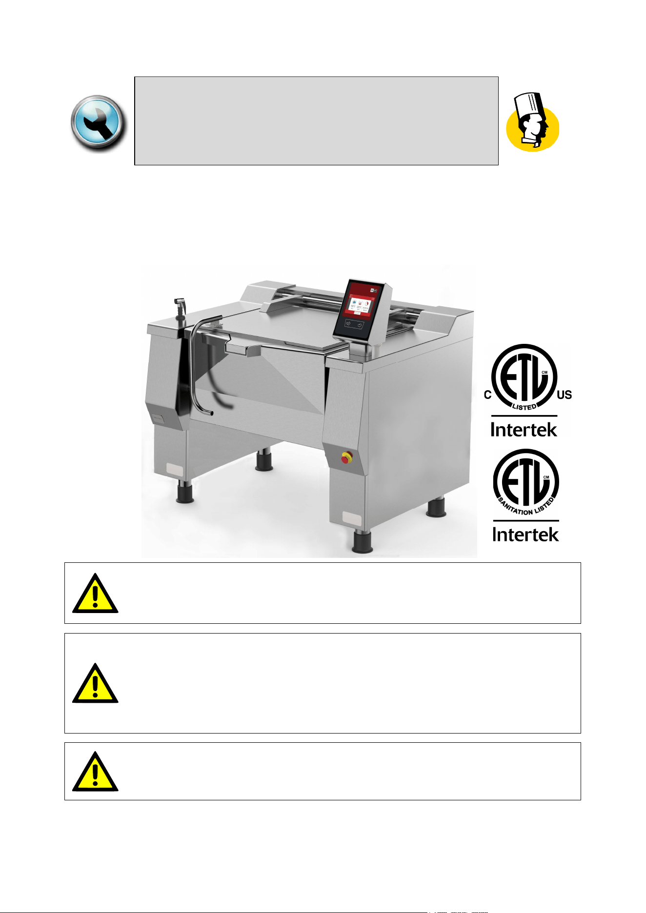
“BETTERPAN”
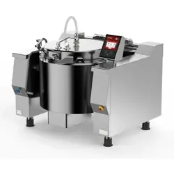
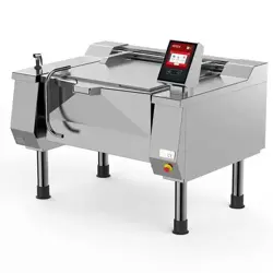
RECTANGULAR BRATT PANS, GAS TYPE
MODD. UDBRG…_V1 ; UDBRG…-C_V1
FOR YOUR SAFETY:
Do not store or use gasoline or any other flammable liquids and
vapours in the vicinity of this or any other appliance.
WARNING:
Improper installation, operation, adjustment, alteration, service or
maintenance can cause property damage, injury or death.
Read the installation, operating and maintenance instructions
thoroughly before installing, operating or servicing this equipment.
PURCHASER: Instructions to be followed in the event that the operator
of this appliance smells gas must be posted in a prominent location.
This information shall be obtained by consulting the local gas supplier.
01
-
UDBRG_V1
-
DIMU
-
00
-
EN
INTRODUCTION
2
IN CASE OF TECHNICAL ASSISTANCE, INDICATE:
MODEL : ______________________________________________________
NR. SERIAL : ______________________________________________________
The model and serial number are indicated on the rating plate
Firex srl, Z.I.Gresal, 28
32036 Sedico
BELLUNO ITALIA
TELEPHONE: (0039) 852700 ; FAX: (0039) 852858
The manual is available upon request to:
specifying model and serial number
(The model and serial number data are indicated on the rating plate)
.

INTRODUCTION
0
1
-
U
DBRG
_V1
-
DIMU
-
00
-
EN
3
TABLE OF CONTENTS
1 INTRODUCTION.................................................................................................................................... 6
1.1 SYMBOLS AND PICTORIALS .................................................................................................................. 6
1.2 GENERAL REMINDERS ........................................................................................................................... 6
1.3 IMPORTANT NOTES FOR INSTALLATION ............................................................................................. 7
2 SAFETY ................................................................................................................................................. 8
2.1 OVERVIEW ............................................................................................................................................... 8
2.2 WARNINGS ............................................................................................................................................... 9
2.3 TABLE OF PAN PRODUCT LEVELS ...................................................................................................... 12
3 DESCRIPTION OF THE MACHINE ..................................................................................................... 13
3.1 DESCRIPTION ........................................................................................................................................ 13
3.2 MATERIALS ............................................................................................................................................ 13
3.3 OPTIONAL .............................................................................................................................................. 13
3.3.1 CORE PROBE .................................................................................................................................................... 13
3.3.2 SHOWER FOR WASHING ................................................................................................................................. 13
3.3.3 CASTERS ........................................................................................................................................................... 13
3.4 OPERATING PARTS ............................................................................................................................... 14
4 TECHNICAL DATA ............................................................................................................................. 15
4.1 TECHNICAL DATA UDBRG.._V1 ; UDBRG..-C_V1 ............................................................................... 15
4.2 PLANT CONNECTION UDBRG029_V1 ; UDBRG029-C_V1 .................................................................. 16
4.3 PLANT CONNECTION UDBRG038_V1 ; UDBRG038-C_V1 .................................................................. 17
4.4 PLANT CONNECTION UDBRG048_V1 ; UDBRG048-C_V1 .................................................................. 18
4.5 PLANT CONNECTION UDBRG058_V1 ; UDBRG058-C_V1 .................................................................. 19
4.6 GAS INLET PRESSURES ....................................................................................................................... 20
4.7 GAS MANIFOLD PRESSURE; NOZZLES;PRIMARY AIR DISTANCE ................................................... 20
4.8 FIG. MAIN BURNER – PRIMARY AIR REGULATION ............................................................................ 21
4.9 FIG. GAS CONTROL VALVE (822) ......................................................................................................... 22
5 TRANSPORT, STORAGE, UNPACKING............................................................................................ 23
5.1 TRANSPORT .......................................................................................................................................... 23
5.2 STORAGE ............................................................................................................................................... 24
5.3 RECEIPT AND UNPACKING .................................................................................................................. 24
6 INSTALLATION ................................................................................................................................... 25
6.1 INSTALLATION CODES AND STANDARDS .......................................................................................... 25
6.2 REQUIREMENTS FOR THE INSTALLATION SITE ................................................................................ 25
6.3 POSITIONING ......................................................................................................................................... 26
7 CONNECTIONS................................................................................................................................... 27
7.1 ELECTRICAL CONNECTION ................................................................................................................. 27

01
-
UDBRG_V1
-
DIMU
-
00
-
EN
INTRODUCTION
4
7.2 WATER CONNECTION ........................................................................................................................... 28
7.3 GAS CONNECTION ................................................................................................................................ 29
7.3.1 CONTROL OF THE GAS PRESSURE ............................................................................................................... 30
8 COMMISSIONING AND TESTING ...................................................................................................... 31
9 USING THE MACHINE ........................................................................................................................ 32
10 TOUCH SCREEN ................................................................................................................................ 32
11 MAIN MENU ........................................................................................................................................ 33
12 SETTINGS MENU ................................................................................................................................ 34
13 PROGRAMS MENU ............................................................................................................................ 35
14 COOKING LAYOUT ............................................................................................................................ 36
14.1 STATUS BAR .......................................................................................................................................... 37
14.2 COOKING AREA ..................................................................................................................................... 38
14.2.1 COOKING ICONS (MEANING) .......................................................................................................................... 39
14.3 MESSAGE COLUMN (L) ......................................................................................................................... 40
14.4 FUNCTION BAR ...................................................................................................................................... 42
14.4.1 START-STOP KEY FOR RUNNING PROGRAMS............................................................................................. 42
14.4.2 EXTRA KEY ........................................................................................................................................................ 44
14.4.3 COOKING WITH DELAY TIMER KEY ............................................................................................................... 44
15 COOKING METHODS IN DETAIL ....................................................................................................... 45
15.1 COOKING ................................................................................................................................................ 45
16 SETTING SETPOINT PARAMETERS ................................................................................................. 46
16.1 SETTING SETPOINT VALUES WITH THE KEYPAD ............................................................................. 46
17 COOKING PARAMETERS SETTING ................................................................................................. 48
17.1 SETTING COOKING METHOD AND TEMPERATURE .......................................................................... 48
17.2 SETTING COOKING TIME ...................................................................................................................... 48
18 CREATING PROGRAMS (MULTI-PHASE)......................................................................................... 51
18.1 CREATING/DELETING PHASES ............................................................................................................ 51
18.2 MESSAGE SETTINGS ............................................................................................................................ 53
18.3 SAVING A PROGRAM ............................................................................................................................ 57
18.4 EDIT/ COPY/ RENAME PROGRAM ....................................................................................................... 58
18.5 DELETING A PROGRAM ........................................................................................................................ 59
19 RUNNING A PROGRAM/MANUAL COOKING ................................................................................... 59
19.1 RUNNING A PROGRAM/MANUAL COOKING ....................................................................................... 59
19.2 END OF COOKING ................................................................................................................................. 60
20 RUNNING PROGRAMS (MULTI-PHASE)........................................................................................... 61
20.1 RUNNING PROGRAMS (MULTI-PHASE)............................................................................................... 61
20.2 END OF PROGRAM ................................................................................................................................ 63
21 COOKING WITH DELAY TIMER ......................................................................................................... 64
22 FILLING PAN WITH H2O .................................................................................................................... 65

INTRODUCTION
0
1
-
U
DBRG
_V1
-
DIMU
-
00
-
EN
5
22.1 FILLING THE PAN WITH H2O USING A LITRE-COUNTER DEVICE .................................................... 65
22.2 MANUALLY FILLING THE PAN WITH H2O ............................................................................................ 67
23 COOKING WITH BASKETS (MOD.DBR ..-C) ..................................................................................... 68
23.1 SELECTING THE COOKING METHOD .................................................................................................. 68
23.2 SELECTING COOKING TIME ................................................................................................................. 68
23.3 FITTING BARS AND BASKETS .............................................................................................................. 68
23.4 STARTING HEATING .............................................................................................................................. 69
23.5 IMMERSING THE BASKETS .................................................................................................................. 70
23.6 COOKING TIME (BASKET IMMERSION) ............................................................................................... 71
23.7 END OF COOKING/HEATING ................................................................................................................ 71
24 MOVING THE PAN .............................................................................................................................. 72
25 CLEANING AND CARE ...................................................................................................................... 74
25.1 GENERAL INFORMATION ..................................................................................................................... 74
25.2 DAILY CLEANING ................................................................................................................................... 74
25.3 CLEANING THE PRESSURE COOKER SYSTEM ................................................................................. 75
25.4 CLEANING AND CHECKING THE SAFETY VALVE .............................................................................. 75
25.5 PRECAUTIONS IN CASE OF PROLONGED INACTIVITY ..................................................................... 76
25.6 PRECAUTIONS IN CASE OF MALFUNCTION ....................................................................................... 76
26 MAINTENANCE................................................................................................................................... 77
26.1 MAINTENANCE OF THE APPLIANCE ................................................................................................... 77
26.2 PERIODIC MAINTENANCE .................................................................................................................... 77
27 DISPLAY MESSAGES ........................................................................................................................ 79
01
-
UDBRG_V1
-
DIMU
-
00
-
EN
INTRODUCTION
6
1 INTRODUCTION
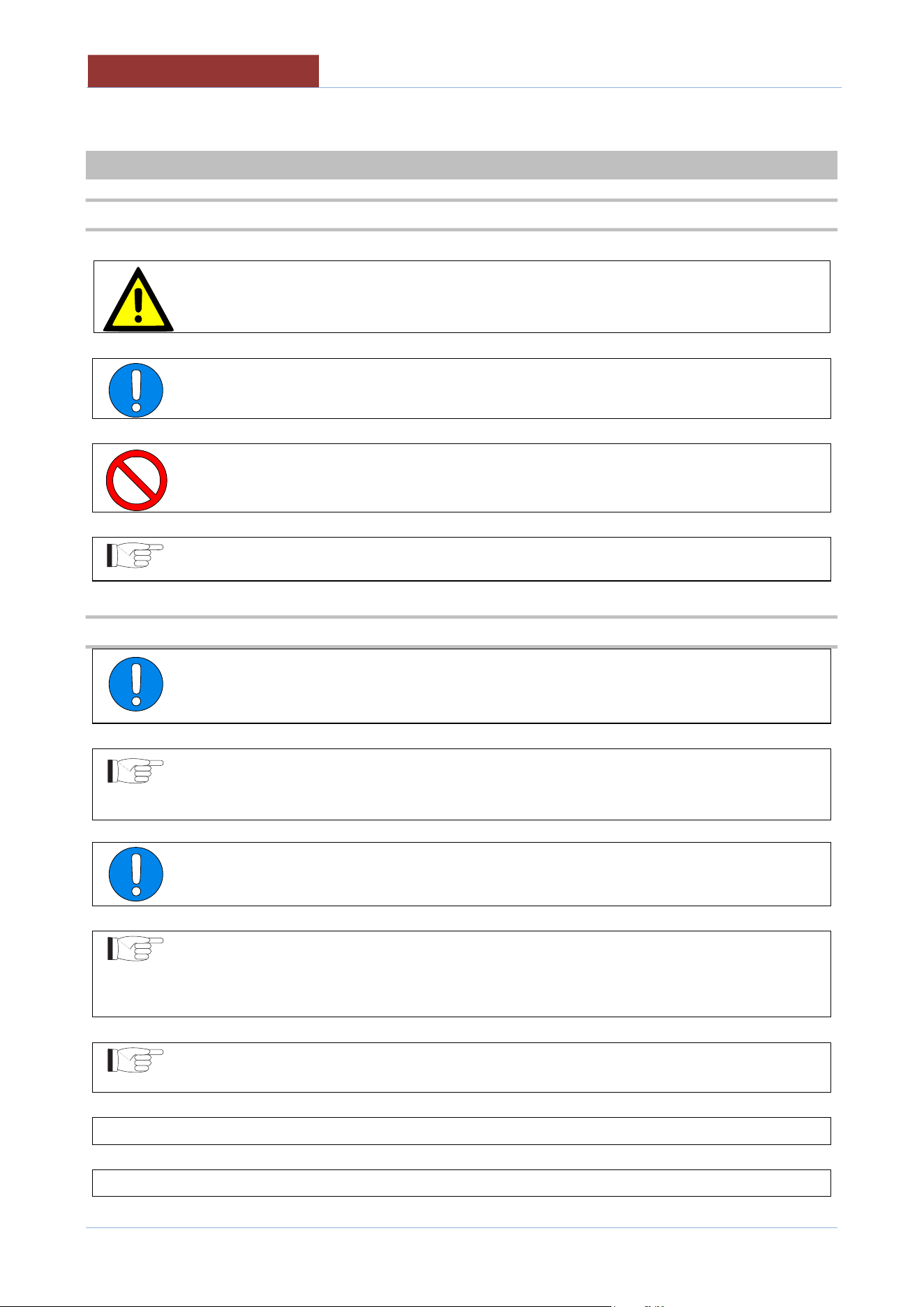
1.1 SYMBOLS AND PICTORIALS
ATTENTION!
This indicates a dangerous operation or situation.
ATTENTION!
This indicates a regulation or an obligation.
ATTENTION!
This indicates the prohibition to carry out an operation.
NOTE!
This indicates a recommendation or information deemed to be particularly important.
1.2 GENERAL REMINDERS
The business units manager, where the unit will be installed, have an obligation, in
accordance with the regulations, read carefully the contents of this manual and teach
the operators and maintainers involved for parts that they compete.
This manual contains all the necessary information for correct and safe use of our appliances.
Ensure this manual is conserved correctly so that it is always available to all users of
the machine!
All installation work must only be carried out by a company belonging to the relevant
industry register.
The manufacturer does not assume any responsibility or warranty commitment for
accidents and damage due to non-compliance with the requirements or installation or
maintenance not in accordance with safety standards.
Also applies in case of improper use of the appliance by the operator.
Any damage caused by water/steam infiltration or insects, due to the machine panels
not being closed (after installation or maintenance) shall void any warranty claims.
Do not attempt to operate this unit in the event of a power failure.
Intended for commercial use only. Not for household use
INTRODUCTION
0
1
-
U
DBRG
_V1
-
DIMU
-
00
-
EN
7
1.3 IMPORTANT NOTES FOR INSTALLATION
The following points are to insure the safe installation and operation of this equipment:
Before connecting any parts of the appliance to supplies, make sure that the latter is
equivalent the requirements stated in the rating plate, if the appliance has been
designed for these supplies.
Observe all clearance requirements.
Disconnect the electrical power supply to the appliance before cleaning or servicing
unit.
All service must be performed by a qualified Technician.
Keep the appliance area free and clear of combustible materials.
Do not obstruct the flow of combustion and ventilation air.
Keep adequate distance for air openings into the combustion chamber.
Always wear the personal protective equipment required by the regulations.
Follow the fire prevention regulations very carefully.
In the water and gas supply systems the absence of "water hammer" must be
guaranteed.
Damage to the operation of the machine.

01
-
UDBRG_V1
-
DIMU
-
00
-
EN
SAFETY
8
2 SAFETY
2.1 OVERVIEW
Read the warnings contained in this manual carefully as they provide important information
regarding safe
installation, maintenance and use.
These appliances should only be used by personnel trained to use them.
The appliance must be operated under close supervision.
The appliance must only be used for the purpose for which it was explicitly designed, any other
use is improper and as a result considered dangerous.
This appliance is intended for professional use and therefore must be used by appropriately
trained personnel
Take particular care during operation as the outside of the appliance
can also become very hot!
It is essential to contact a specialist support centre for any repairs or maintenance.
All the important information about the appliance for technical support can be found on the rating
plate .
When requesting technical support, you should describe the problem in detail in order to allow the
technician to immediately understand the cause and type of fault.
Certain operational faults may be due to operator error, therefore it is important for staff to receive
comprehensive training.
SAFETY
0
1
-
U
DBRG
_V1
-
DIMU
-
00
-
EN
9
2.2 WARNINGS
All installation and maintenance work must only be carried out by a company
belonging to the relevant industry register.
Fire protection regulations must be strictly adhered to.
The machine should be serviced at least once a year to ensure it is in prime
condition. Therefore, it is recommended to sign a maintenance contract with a reliable
technical support centre.
The appliance can only be used for cooking food in industrial kitchens. Any other use is
considered improper use and, therefore, dangerous.
Intended for commercial use only. Not for household use.
The appliances should only be used by personnel trained to use them.
The appliance must be operated under close supervision.
Keep the appliance area free and clear of combustible materials.
Do not attempt to operate this unit in the event of a power failure.
Do not obstruct the flow of combustion and ventilation air.
Respect a 5 minute complete shuttoff period before the appliance is relighted.
Any damage caused by water/steam infiltration or insects, due to the machine
panels not being closed (after installation or maintenance) shall void any warranty
claims.
The manufacturer assumes no responsibility for injuries or damage due to non-
compliance with safety regulations or improper use of the appliance by the
operator.
The appliance is not intended to be used by persons (including children) with
reduced physical, sensory or mental abilities, or lack of experience or knowledge,
unless they are supervised, by someone responsible for their safety, or given
instructions regarding the use of the appliance.
Children should be supervised at all times so that they do not play with the
appliance.
01
-
UDBRG_V1
-
DIMU
-
00
-
EN
SAFETY
10
Wear rubber gloves, goggles or a face shield and protective clothing when using
the appliance.
Risk of scalding!
The machine controls can only be hand operated. Damage caused by the use of
pointed, sharp and similar objects shall void any warranty claims.
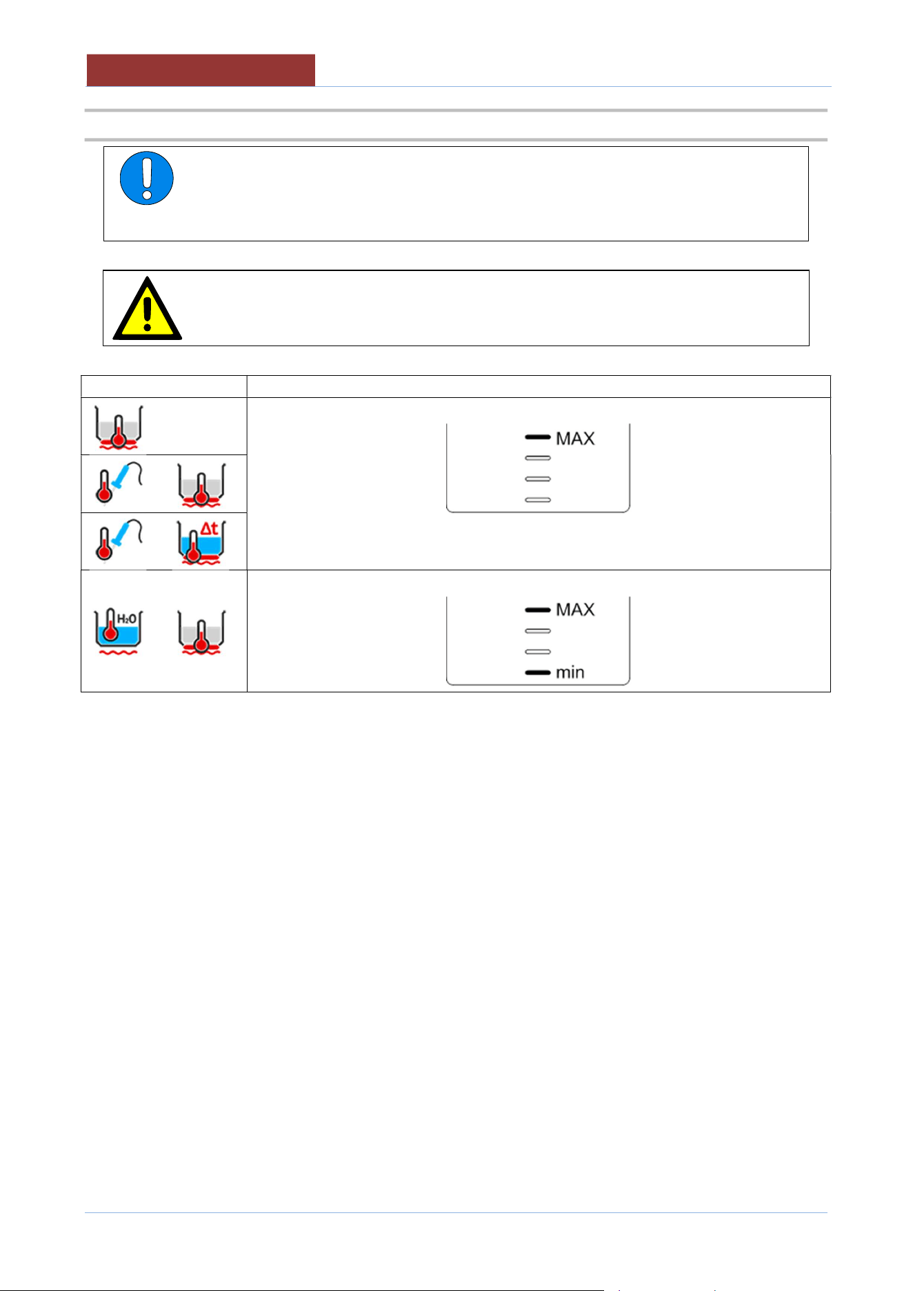
It is essential to wash the inside of the cooking pan thoroughly before setting up
the appliance for first use.
The cooking pan must be filled respecting the minimum and maximum values
(including the food to be cooked) indicated in the table depending on the cooking
method.
When emptying the pan, the operator must position him/herself on the right-hand
side of the machine (control side) being careful of any hot content spilling from
the pan and avoiding any splashes.
The operator must also ensure that any persons present in the room maintain a
safe distance of at least 2 metres from the perimeter of the machine, both while
emptying and replacing the pan.
Take particular care during operation as the surfaces become hot.
When filling the pan with water, using a tap or shower (optional), make sure that
there is no hot oil in the pan.
The appliance must be disconnected from the power supply during cleaning,
maintenance and replacement of the internal parts.
When cleaning the appliance, never use jets of water or a steam cleaner to avoid
infiltration and damage to components.
Most cleaning products are harmful to the skin, eyes, mucous membranes, and
clothes. Precautions must be taken. Wear rubber gloves, safety glasses/goggles
or a face shield, and protective clothing. Read the warnings carefully and follow
the directions on the label of the detergent.
The floor may be slippery in the area around the appliance.
If the power cord is damaged, it must be replaced by the manufacturer or by a
servicing company or a similarly qualified person in order to avoid hazards.
When an appliance is supplied on casters (optional), there is a restraint on the
appliance and, if disconnected of the restraint is necessary, to reconnect this
restraint after the appliance has been returned to its original position.
Switch off the appliance in case of breakdown, malfunction or water leakage.
Disconnect all water, electricity and gas supplies and contact a support centre.

SAFETY
0
1
-
U
DBRG
_V1
-
DIMU
-
00
-
EN
11
In the event of a fire, cover the cooking pan by closing the lid and disconnect all
water, electricity and gas supplies.
NEVER USE WATER to extinguish a fire.
Do not store or use flammable gases or liquids near the machine.
01
-
UDBRG_V1
-
DIMU
-
00
-
EN
SAFETY
12
2.3 TABLE OF PAN PRODUCT LEVELS
ATTENTION:
The cooking pan must be filled respecting the minimum and maximum values
(including the food to be cooked) indicated in the table depending on the cooking
method.
ATTENTION:
Failure to comply with this requirement may cause serious injury to persons and
compromise the operation of the appliance
Cooking method
PAN LEVELS TO BE RESPECTED
DESCRIPTION OF THE MACHINE
0
1
-
U
DBRG
_V1
-
DIMU
-
00
-
EN
13
3 DESCRIPTION OF THE MACHINE
3.1 DESCRIPTION
Electronically controlled rectangular multipurpose bratt pans.
Designed to perform the main types of cooking: braising, boiling, pressure cooking and frying.
UDBR..-C versions with automatic basket lifting system.
The appliance can only be used for cooking food in industrial kitchens. Any other use is
considered improper use and, therefore, dangerous
3.2 MATERIALS
Cooking pan in AISI 304 grade stainless steel
Double-walled lid in AISI 304 grade stainless steel
Outer cover in fine satin AISI 304 grade stainless steel.
Self-supporting frame in AISI 304 grade stainless steel.
Adjustable feet for levelling in AISI 304 grade stainless steel, equipped with removable cover for cleaning
operations.
3.3 OPTIONAL
3.3.1 Core probe
For precise temperature measurements, insert the probe in the centre of the product to be processed, ensuring
that it is as far in as possible.
When not used, always place the probe in the appropriate housing on the lid to avoid any
damage.
3.3.2 Shower for washing
The shower has a twist-out type system. Pull out gently until the desired or maximum length is reached. To
return, it is necessary to tug gently outwards and then twist it back into position.
Press the black lever to operate the water jet. The flow of water immediately stops when released. If you want
to have a continuous jet of water, turn the black lever as far as you can.
Handle this accessory with care and store it in its housing at the end of each use to avoid
damaging it.
Make sure there is no hot oil in the pan before using the jet.
3.3.3 Casters
The appliances can be installed on casters. The front two have brakes: to engage them, press gently on the
lever above the castor, to release them, press more firmly.
Always engage the castor brakes if you do not have to move the appliance.
01
-
UDBRG_V1
-
DIMU
-
00
-
EN
DESCRIPTION OF THE MACHINE
14
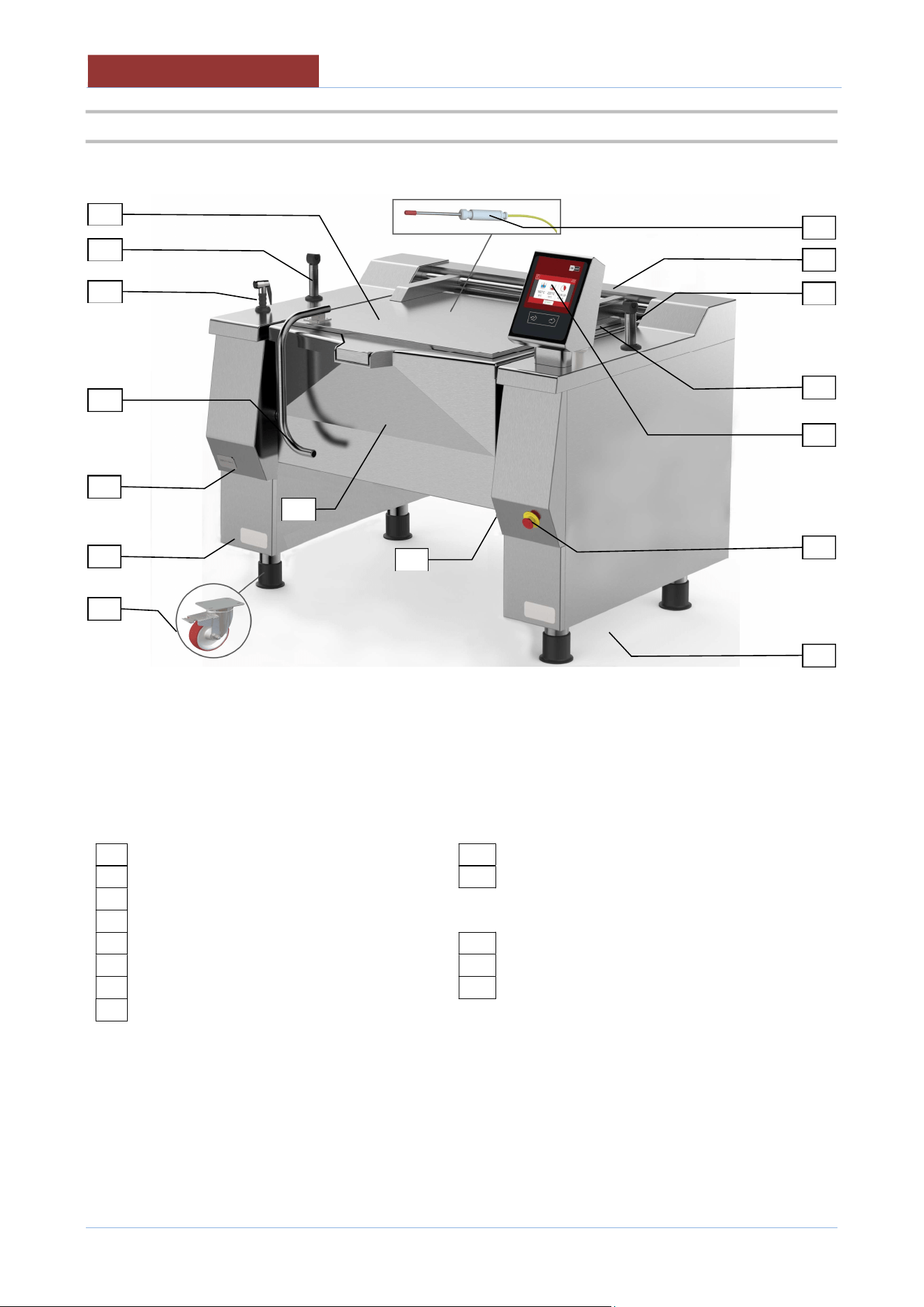
3.4 OPERATING PARTS
01
Technical Data Plate
09
Basket lifter (mod.
-
C)
02
Emergency button
10
Steam vent (gas)
03
USB slot
04
Touch Screen
OPTIONAL
05
Cooking pan
20
Core probe
06
Fill tap
21
Shower
07
Lid
22
Castors
08
Lid handle
07
21
20
05
08
12
10
09
06
04
03
01
02
22
01
09
TECHNICAL DATA
0
1
-
U
DBRG
_V1
-
DIMU
-
00
-
EN
15
4 TECHNICAL DATA
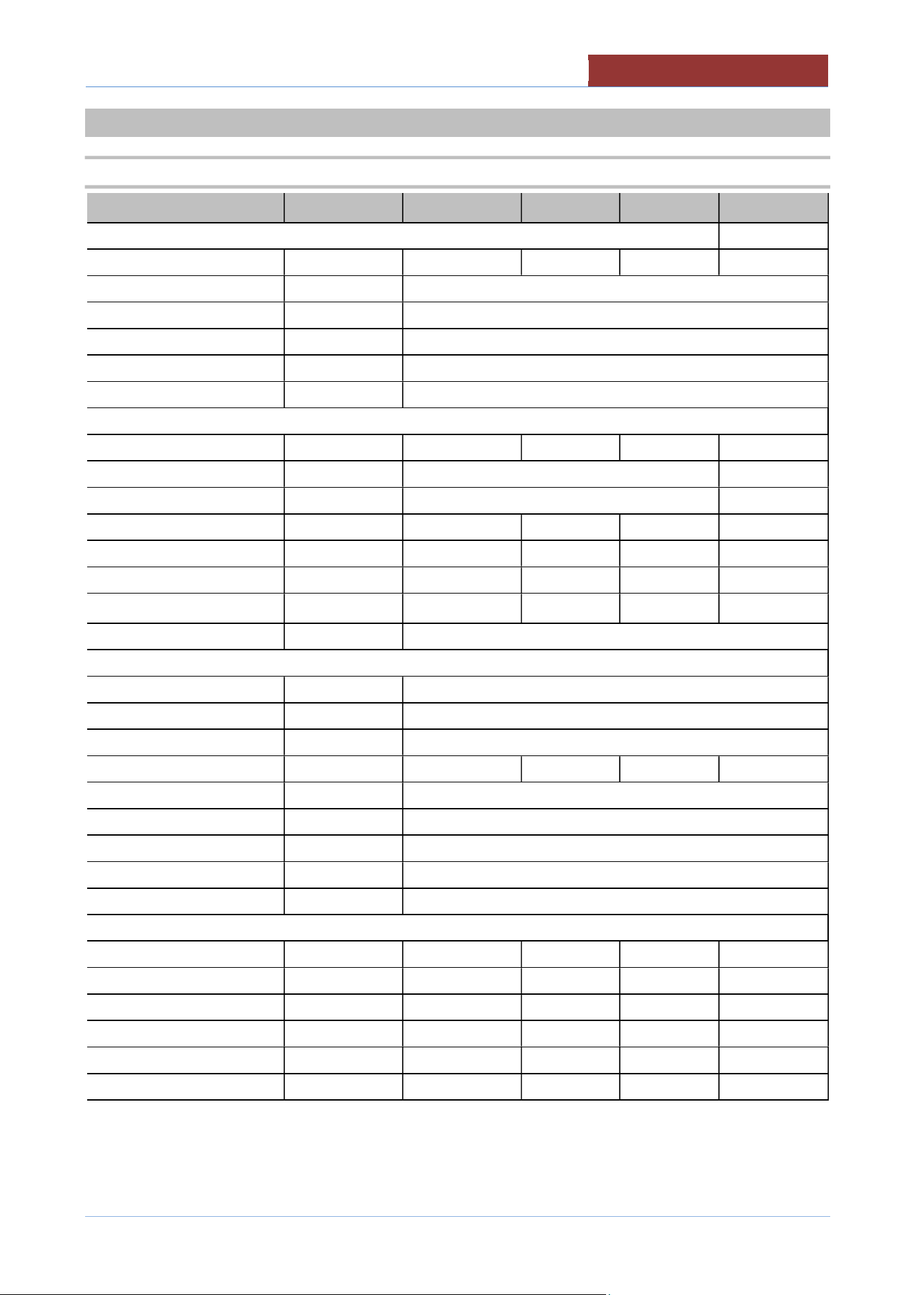
4.1 TECHNICAL DATA UDBRG.._V1 ; UDBRG..-C_V1
UDBRG.._V1 029 038 048 058
TECHNICAL DATA (DIMEMSIONS)
Equipment dim.A Inches 57.87 67.91 78.74 88.78
Equipment dim.B Inches 44.29
Equipment dim.H1 Inches 50.51
Equipment dim.H Inches 37.40
Equipment dim.H2 Inches 75.98
Tank drain height H3 Inches 19.09
TECHNICAL DATA (FUNCTIONALITY)
Pan dimension A Inches 31.69 41.73 52.56 62.60
Pan dimension B Inches 25.59
Pan dimension H Inches 16.54
Pan area Inches² 806 1069 1348 1596
Overvall volume Gallons 34 45 57 68
Useful volume Gallons 29 38 48 58
Basket lifting (mod.-C)
no. (GN)
2 (1/1) 3 (1/1) 4 (1/1) 4 (1/1)
Temperature °F (°C) 68÷482 (20÷250)
TECHNICAL DATA (INSTALLATION)
Electric power ** kW 0.5
(E) Voltage/Input ** V (A) 2 PHASE 208V (2.4 A) ; 2 PHASE 220-240 V (2.1 A)
IPX IPX 5
Gas power BTU/HR 95,500 119,500 143,500 179,000
(G) Gas connection Ø" 3/4 " NPT
Water pressure PSI (kPa) 25-50 (170-345)
(A) Hot water inlet Ø" 3/4 "
(B) Cold water inlet Ø" 3/4 "
Sound level dbA < 70
TECHNICAL DATA (STORAGE/MOVEMENT)
Packaging dim.A Inches 63 72 84 94
Packaging dim.B Inches 48 48 48 48
Packaging dim.H Inches 58 58 58 58
Volume ft³ 101 116 136 151
Net weight lbs 1014 1146 1268 1322
Gross weight lbs 1202 1367 1500 1565
**Verify on rating plate
01
-
UDBRG_V1
-
DIMU
-
00
-
EN
TECHNICAL DATA
16
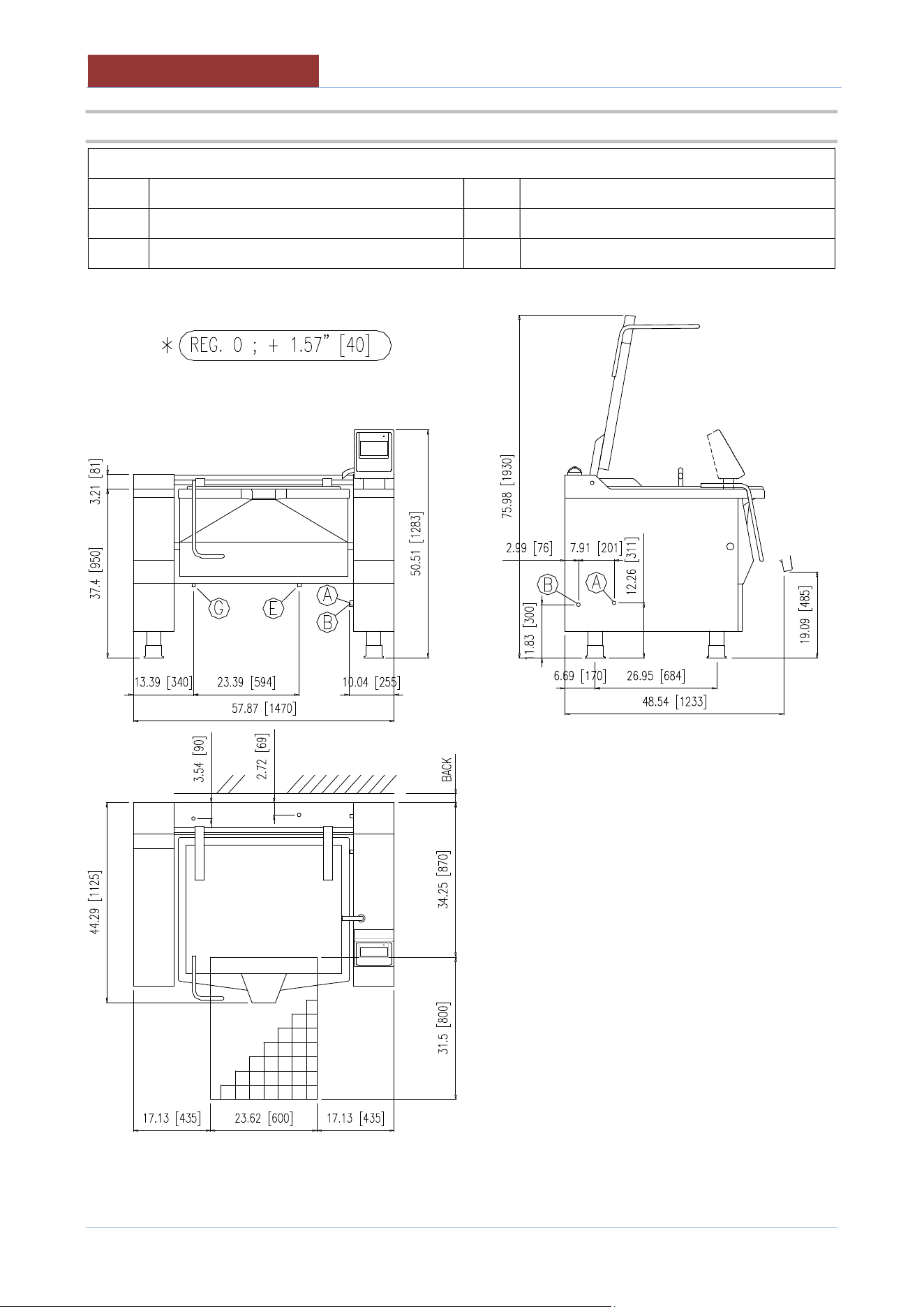
4.2 PLANT CONNECTION UDBRG029_V1 ; UDBRG029-C_V1
LEGEND:
E Electrical connection A Hot water connection
G Gas connection B Cold water connection
BACK
See “CLEARANCE REQUIREMENTS”
TECHNICAL DATA
0
1
-
U
DBRG
_V1
-
DIMU
-
00
-
EN
17
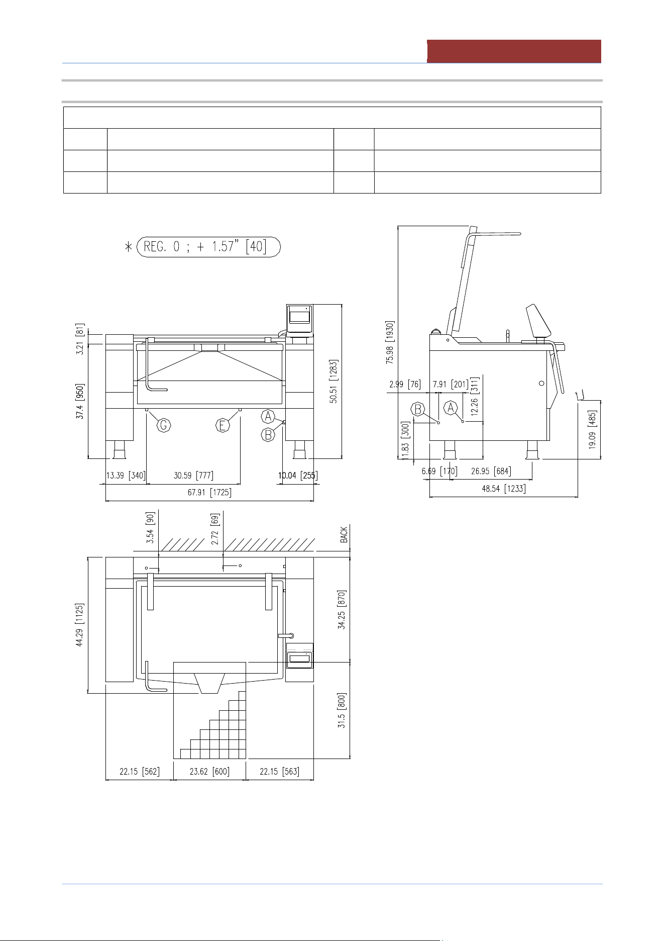
4.3 PLANT CONNECTION UDBRG038_V1 ; UDBRG038-C_V1
LEGEND:
E Electrical connection A Hot water connection
G Gas connection B Cold water connection
BACK
See “CLEARANCE REQUIREMENTS”
01
-
UDBRG_V1
-
DIMU
-
00
-
EN
TECHNICAL DATA
18
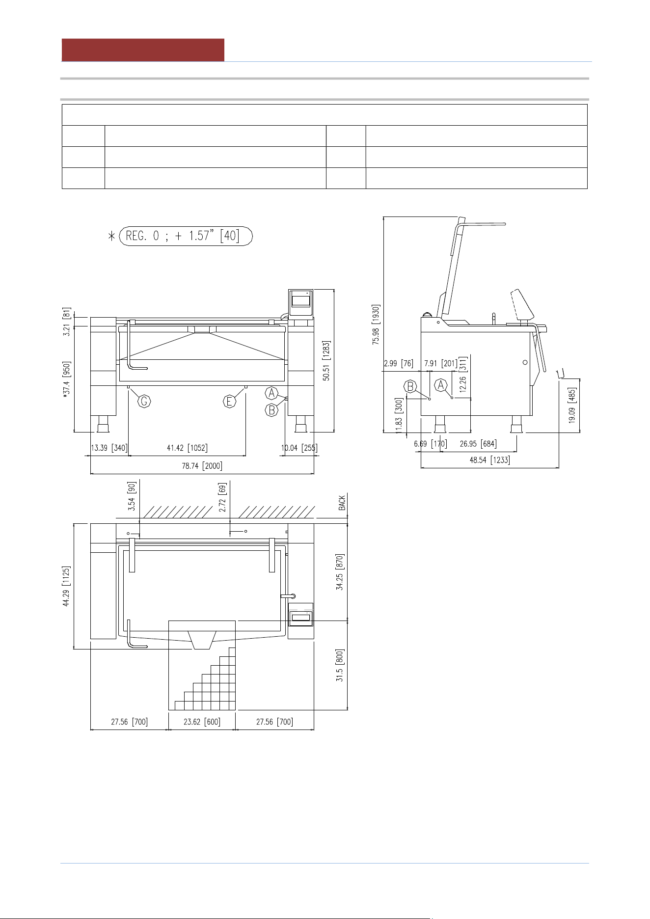
4.4 PLANT CONNECTION UDBRG048_V1 ; UDBRG048-C_V1
LEGEND:
E Electrical connection A Hot water connection
G Gas connection B Cold water connection
BACK
See “CLEARANCE REQUIREMENTS”
TECHNICAL DATA
0
1
-
U
DBRG
_V1
-
DIMU
-
00
-
EN
19
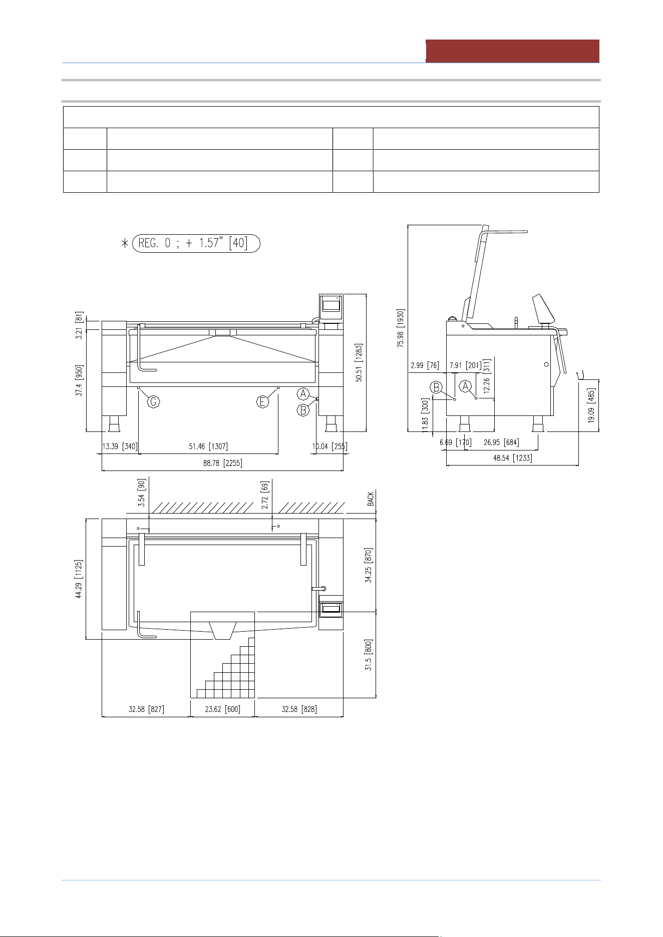
4.5 PLANT CONNECTION UDBRG058_V1 ; UDBRG058-C_V1
LEGEND:
E Electrical connection A Hot water connection
G Gas connection B Cold water connection
BACK
See “CLEARANCE REQUIREMENTS”
01
-
UDBRG_V1
-
DIMU
-
00
-
EN
TECHNICAL DATA
20
4.6 GAS INLET PRESSURES
GAS REQUIREMENT TABLE Type of gas
Natural Propane
Operating gas pressure in W.C. (mbar) 7.0 (17.4) 11.0 (27.4)
Min.Supply gas pressure in W.C. (mbar) 6.0 (14.9) 9.0 (22.4)
Max.Supply gas pressure in W.C. (mbar) 10.5 (26.1) 13.0 (32.3)
Warning: if the supply pressure is lower than “ Min.Supply gas pressure”, the icon appears in the display
and the heating does not activate.
Contact your gas company for correct supply line sizes.
Warning: if the supply pressure exceeds “ Max.Supply gas pressure”, a pressure regulator must be installed, to
provide a maximum of 10,5” W.C (for natural gas) or 13” W.C (for propane gas) gas pressure to the gas control valve.
4.7 GAS MANIFOLD PRESSURE; NOZZLES;PRIMARY AIR DISTANCE
UDBRG.._V1 029 038 048 058
Rated heating power BTU/HR 95,500 119,500 143,500 179,000
MANIFOLD PRESSURE
Natural gas
in W.C. (mbar)
6.4 (15.9) 6.3 (15.6) 6.0 (15.0) 5.7 (14.3)
Propane gas in W.C. (mbar)
10.4 (25.9) 10.6 (26.4) 10.0 (24.8) 10.4 (25.9)
NOZZLES
(Nr.x
Ø)
Natural gas
Ø 1/100 mm
8
x
160
10
x
165
13
x
180
15
x
195
Propane gas
Ø 1/100 mm
8
x
110
10
x
110
13
x
110
15
x
110
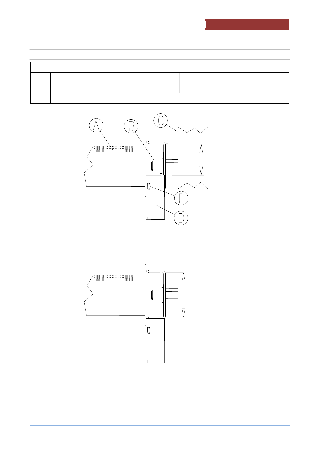
PRIMARY AIR DISTANCE
(H)
Natural gas
Inches (
mm
)
0.039 (1)
0.039 (1)
0.039 (1)
0.039 (1)
Propane gas
Inches (
mm
)
0.59 (15)
0.59 (15)
0.59 (15)
0.59
(15)
TECHNICAL DATA
0
1
-
U
DBRG
_V1
-
DIMU
-
00
-
EN
21
4.8 FIG. MAIN BURNER – PRIMARY AIR REGULATION
LEGEND:
A Burner D Air regulation square
B Injector (tab."GAS DATA") E Square lock screws
C Injector pipe H See tab."GAS DATA"
01
-
UDBRG_V1
-
DIMU
-
00
-
EN
TECHNICAL DATA
22
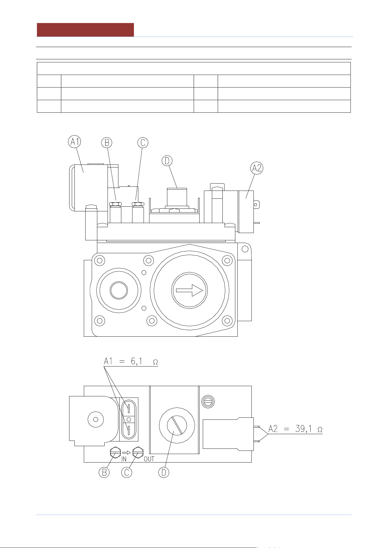
4.9 FIG. GAS CONTROL VALVE (822)
LEGEND:
A1 Coil 6,1 Ω (EV1) C Outlet pressure intake (manifold pressure)
A2 Coil 39,1 Ω (EV2) D Pressure o regulator
B Inlet pressure intake (supply pressure)
TRANSPORT, STORAGE, UNPACKING
0
1
-
U
DBRG
_V1
-
DIMU
-
00
-
EN
23
5 TRANSPORT, STORAGE, UNPACKING
5.1 TRANSPORT
The movement of the machine must be performed by a qualified operator for use of
lifting and transport equipment in accordance with the laws of the country of the user
of the machine.
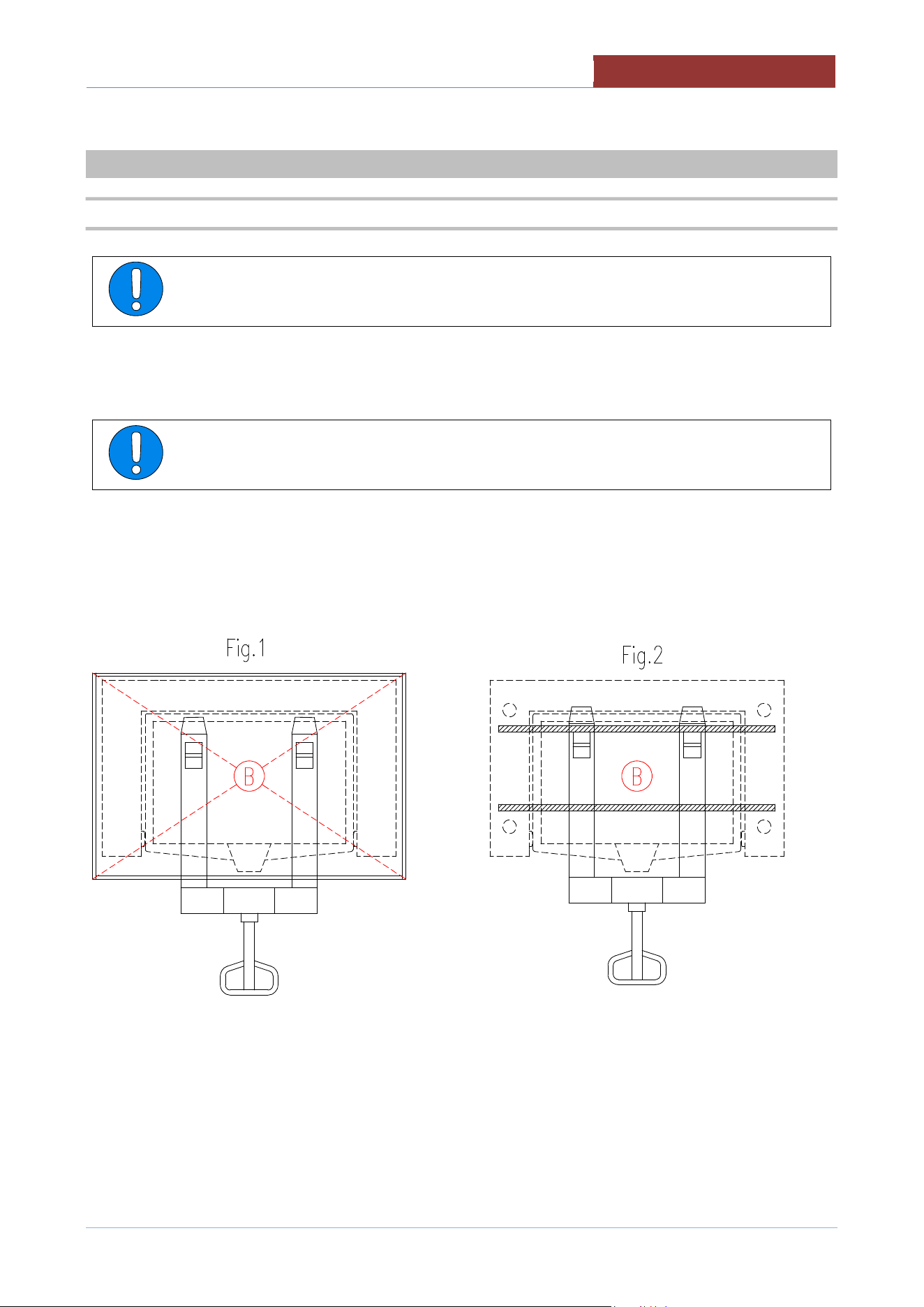
The machine can be transported with a normal means (forklift or transpallet)capable of supporting its weight
and size (see.tab. "TECHNICAL DATA").
Always check the correct balance of the weight of the machine (B = center of gravity)
to prevent unexpected movement or dropping to the floor of the car with damage to
people or things around you.
For transport on pallets, Fig.1
For transport without pallets, Fig.2
01
-
UDBRG_V1
-
DIMU
-
00
-
EN
TRANSPORT, STORAGE, UNPACKING
24
5.2 STORAGE
Store the appliance in a closed environment protected against atmospheric agents.
Keep the appliance away from humidity and temperature ranges
Protect the appliance from shocks and stresses
Ensure that the appliance is in contact with corrosive substances
5.3 RECEIPT AND UNPACKING
Upon receipt of the machine check that the packaging is undamaged. If it does not withdraw
the conditional commodity producing photographic evidence of any apparent damage.
After removing the packaging, check that the appliance is undamaged.In case of
visible damage, do not connect the appliance but contact the sales outlet
immediately.
Check for the presence of individual components with packing lists.
Remove from the panels of the machine the protective film PVC .
Before disposing of the packaging materials make sure that they do not contain machine
elements
(accessory; tools; documentation, etc)
Dispose of the packaging components in accordance with the regulations in force on
waste disposal.

INSTALLATION
0
1
-
U
DBRG
_V1
-
DIMU
-
00
-
EN
25
6 INSTALLATION
6.1 INSTALLATION CODES AND STANDARDS
Installation must conform with local codes, or in the absence of local codes, with the National Fuel Gas Code,
ANSI Z223.1/NFPA 54, or the Natural Gas and Propane Installation Code, CSA B149.1, as applicable.
1. The appliance and its individual shut off valve must be disconnected from the gas supply piping
system during any pressure testing of that system at pressures in excess of ½ psi (3.5 kPa).
2. The appliance must be isolated from the gas supply piping system by closing its individual
manual shut off valve during any pressure testing of the gas supply piping system at test
pressures equal to or less than ½ psi (3.5 kPa).
Electrical grounding must be provided in accordance with local codes, or in the absence of local
codes, with the National Electrical Code, ANSI/NFPA 70, or the Canadian Electrical Code, CSA
C22.2, as applicable.
The electrical diagram is located on the inside of side panel of right hand console.
6.2 REQUIREMENTS FOR THE INSTALLATION SITE
The room in which the appliance is to operate must be well ventilated.
The appliance belongs to the installation class A1 (no direct connection of a chimney of flue exhaust system is
required), so it is very important for the environment in which it is installed to be well-aired and provided with all
the safety openings prescribed for its power.
VENTILATION
The appliance are only to be installed under a ventilation hood in a room which has provisions for
adequate make up air.
Information on the construction and installation of ventilating hoods may be obtained from the
standard for “Vapor Removal from Cooking Equipment”, NFPA No. 96 (latest edition), available
from the National Fire Protection Association, Batterymarch Park, Quincy, MA, USA, 02269.
The gas shut off valve, the electrical isolating switch and the water shutoff valves must
both be located near to the appliance, within easy reach for the user.
01
-
UDBRG_V1
-
DIMU
-
00
-
EN
INSTALLATI
ON
26
6.3 POSITIONING
CLEARANCE REQUIREMENTS
This unit must be installed in accordance with the clearances shown on the rating label which is adhered to the
unit.
CLEARANCES
Combustible construction
Noncombustible construction
Back 8 “ (200 mm) 2 ” (50 mm)
Right Side
0"
0"
Left Side
0"
0"
"Suitable for installation on combustible floors"
There are no particular prescriptions regarding side distances from other appliances, however it is advisable to
leave enough space (20/30 “ : 50/70 cm) in case of maintenance and/or repairs.
The appliance must stand level. Small differences in level can be eliminated by screwing or
unscrewing the adjustable feet. A significantly uneven or sloping stance can affect the
operation of the appliance adversely.
Adjust the bottom foot on each leg to overcome an uneven floor.
If the appliance is equipped with casters (optional), leveling must be ensured by the floor. If
the floor is not level, it must be made such with thicknesses in correspondence of the wheels.
The surface and the inclination of the shims must be such as not to affect the stability of the
machine.
After positioning remove the bars under the frame.
It is advisable to keep the bars so that they are available for subsequent movements.
CONNECTIONS
0
1
-
U
DBRG
_V1
-
DIMU
-
00
-
EN
27
7 CONNECTIONS
Attention: When the appliance is equipped with casters (optional), the installation shall
be made with a connector complying with either ANSI Z21.69 CSA 6.16 and a quick-
disconnect device complying with ANSI Z21.41 CSA 6.9.
Adequate means must be provided to limit the moviment of the appliance without
depending on the connector and the quick-connector device or its associated piping to
limit the appliance movement.
The location where the restraining means may be attached to the appliance are the two
eyebolts positioned on the back of the appliance.
Utility connections must be made with flexible lines of sufficient length to allow the
equipment to be moved for cleaning of the equipment and adjacent area.
7.1 ELECTRICAL CONNECTION
During installation, observe the regulations provided by the local electricity company.
The appliance is supplied to operate according to the power supply indicated on
appliance's rating plate.
A separate fused disconnect switch must be supplied and installed. The appliance must be
electrically grounded by the installer.
The
earthing system must be efficient.
The electric supply must match the power requirements specified on the appliance's rating
plate.
The copper wiring must be adequate to carry the required current at the rated voltage.
The connection point is indicated in the "PLANT CONNECTION"
Ensure main power is turned off before connecting wires.
Remove the screws of the cover in the right side of the appliance. Remove the cover.
01
-
UDBRG_V1
-
DIMU
-
00
-
EN
CONNECTIONS
28
Insert the cable through the cable gland. Carefully connect the conductors to the corresponding terminals. The
earth conductor must be longer than the other conductors, so as to disconnect last in the event of a strong pull
of the cable or break of the cable gland. Tighten the cable gland.
Replace the cover and secure it with screws.
Any damage caused by water/steam infiltration or insects, due to the machine panels
not being closed (after installation or maintenance) shall void any warranty claims.
7.2 WATER CONNECTION
The equipment is to be installed with adequate backflow protection to comply with
applicable federal, state, and local codes.
The water pressure in the supply network must be between the values indicated in the
"INSTALLATION TECHNICAL DATA" table.
If not, install a pressure reducer upstream of the appliance.
Before making the water connection, carefully clean the connection pipe. It is
advisable to let the water flow to clean the whole piping. Any impurities could
compromise the operation of the machine.
The diameter of the connections is indicated in "INSTALLATION TECHNICAL DATA"
The connection point is indicated in the "PLANT CONNECTION"
Install a shut-off valve upstream of the appliance, one for each water connection on the appliance, near the
appliance and in a position easily accessible by the user.
CONNECTIONS
0
1
-
U
DBRG
_V1
-
DIMU
-
00
-
EN
29
7.3 GAS CONNECTION
The choice of the gas piping depends on the diameter required for the type of gas, appliance and installation
and should be performed in conformity with current regulations.
The rating plate on the lower right side of the unit indicates the type of gas your unit is
equipped to burn. Do NOT connect to any other gas type.
Each unit is equipped with an internal pressure regulator .
The manifold pressure is show in table “GAS MANIFOLD PRESSURE”
An adequate gas supply is imperative.
Undersized or low pressure lines will restrict the volume of gas required for satisfactory performance.
Fluctuations of the normal supply pressure more than 20% on natural gas, and 10% on propane gas, will
create problems and affect burner operating characteristics.
The gas inlet pressure is show in table “GAS INLET PRESSURE”
With all units operating simultaneously, the manifold pressure on all units should not show any appreciable
drop.
Purge the supply line to clean out any dust, dirt, or other foreign matter before connecting the line to the unit.
It is recommended that an individual manual shut off valve be installed in the gas supply line to the unit.
Use pipe joint compound which is suitable for use with LP gas on all threaded connections. Test pipe
connections thoroughly for gas leaks.
WARNING:
All connections must be checked for leaks, after the unit has been put in operation.
Use soapy water only for testing on all gases.
Never use an open flame to check for gas leaks.
NOTICE: If applicable, the vent line from the gas appliance pressure regulator
shall be installed to the outdoors in accordance with local codes or, in the
absence of local codes, with the National Fuel Gas Code, ANSI Z223.1/NFPA 54,
or the Natural Gas and Propane Installation Code CSA B149.1, as applicable.
The diameter of the connections is shown in "TECNICAL DATA"
The point of connection is shown in the "PLANT CONNECTIONS"
01
-
UDBRG_V1
-
DIMU
-
00
-
EN
CONNECTIONS
30
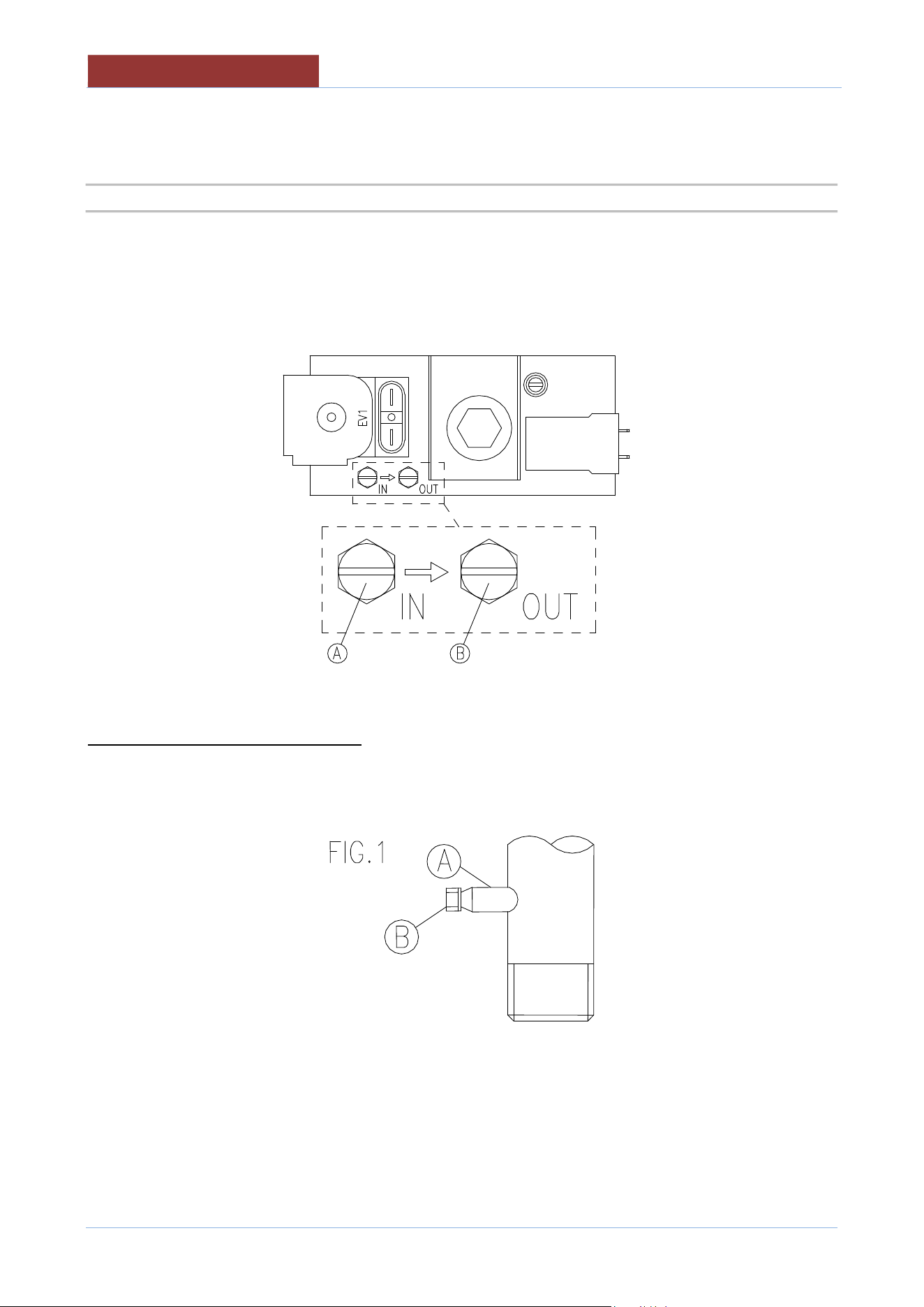
7.3.1 CONTROL OF THE GAS PRESSURE
Gas pressure is measured directly in the gas valve.
A = GAS INLET PRESSURE INTAKE
B = GAS MANIFOLD PRESSURE INTAKE
ONLY FOR THE EUROPEAN MARKET
The gas inlet pressure intake is on the gas feed pipe (FIG.1 "A") (See PLANT CONNECTION).
Before connecting the gauge remove the screw of the inlet pressure intake (FIG.1 "B").
Connect the U manometer and measure the pressure with device functioning.
At the end tighten the screw of the inlet pressure intake.
COMMISSIONING AND TESTING
0
1
-
U
DBRG
_V1
-
DIMU
-
00
-
EN
31
8 COMMISSIONING AND TESTING
Once all the connections have been made, the appliance and the overall installation must be checked
following the directions given in this manual.
CHECK IN PARTICULAR:
That the protective film has been removed from the external surfaces;
That the panels of the machine are closed correctly;
That connections have been made in accordance with the requirements and directions indicated in this
manual;
That all safety requirements in current standards, statutory regulations and directives have been met;
That the power cable is not subjected to traction and is not in contact with hot surfaces;
That the water, gas and steam connections are tight and not subjected to traction.
Now proceed to light the appliance as directed in the instructions for use.
While the appliance is in use, voltage should not differ from the nominal voltage more than +/- 10%.
In the gas models:
Check that the flue gas exhaust is not clogged and that they are expelled without any hindrance.
Repeat "CONTROL OF THE GAS INLET PRESSURE" with the machine running.
If you have other machines connected to the main pipe of the gas, although these have to be put into
operation, to perform a correct control of of the pressure of inlet gas.
The test report must be completed in full and submitted to the customer who should
then sign in acceptance. With effect from this moment, the appliance is covered by the
manufacturer’s warranty
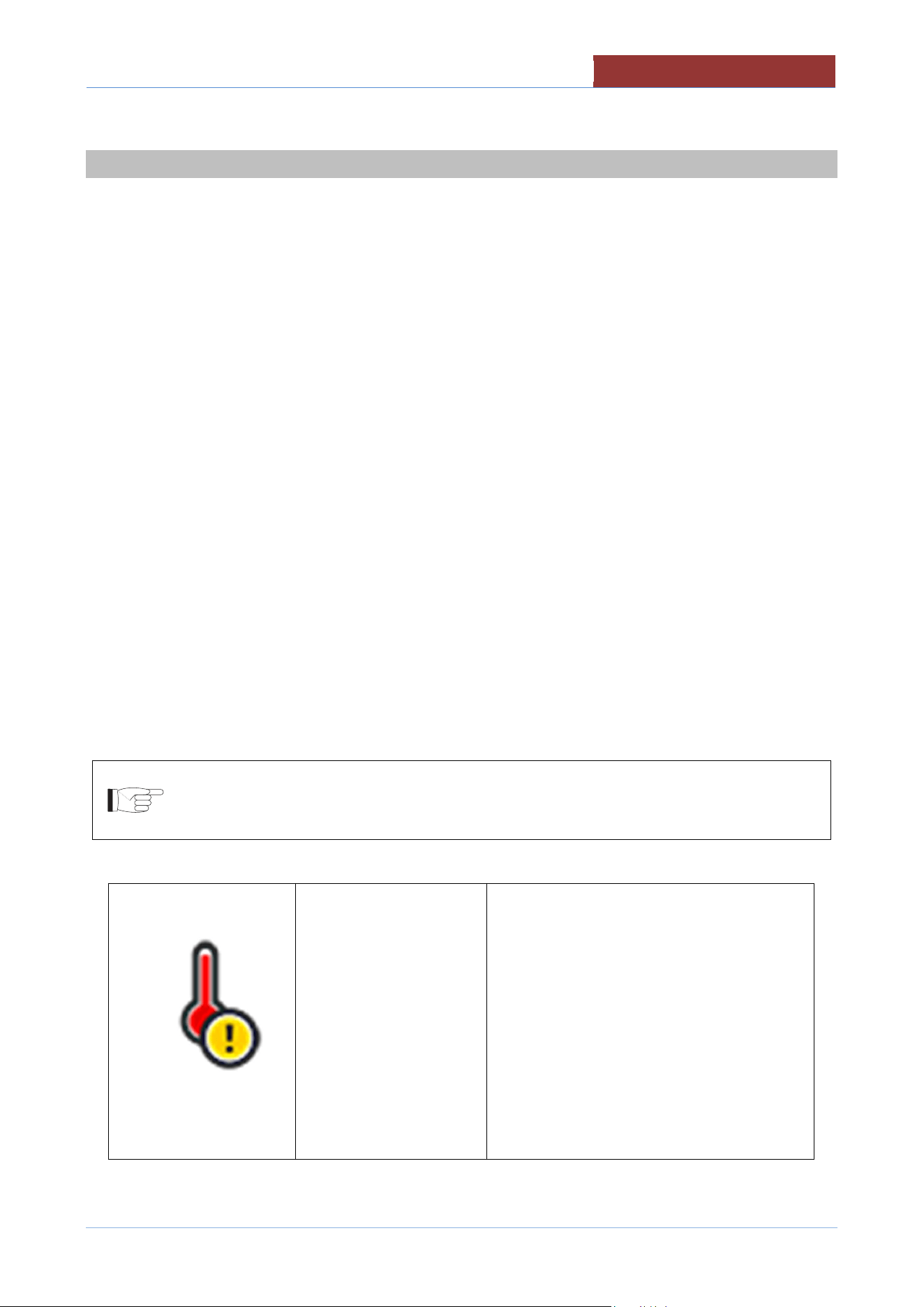
Attention if the display shows:
The safety thermostat of
the equipment has
intervened. The
equipment is switched
off.
The safety thermostat can be disarmed
during transport without any anomalies, or
with temperatures close to 0 ° C
Disconnect the machine from the power
supply.
Remove the lower right control panel and
reset the thermostat, pressing firmly on the
red thermostat button.
In case of new thermostat intervention
contact the assistance service.
9 USING THE MACHINE
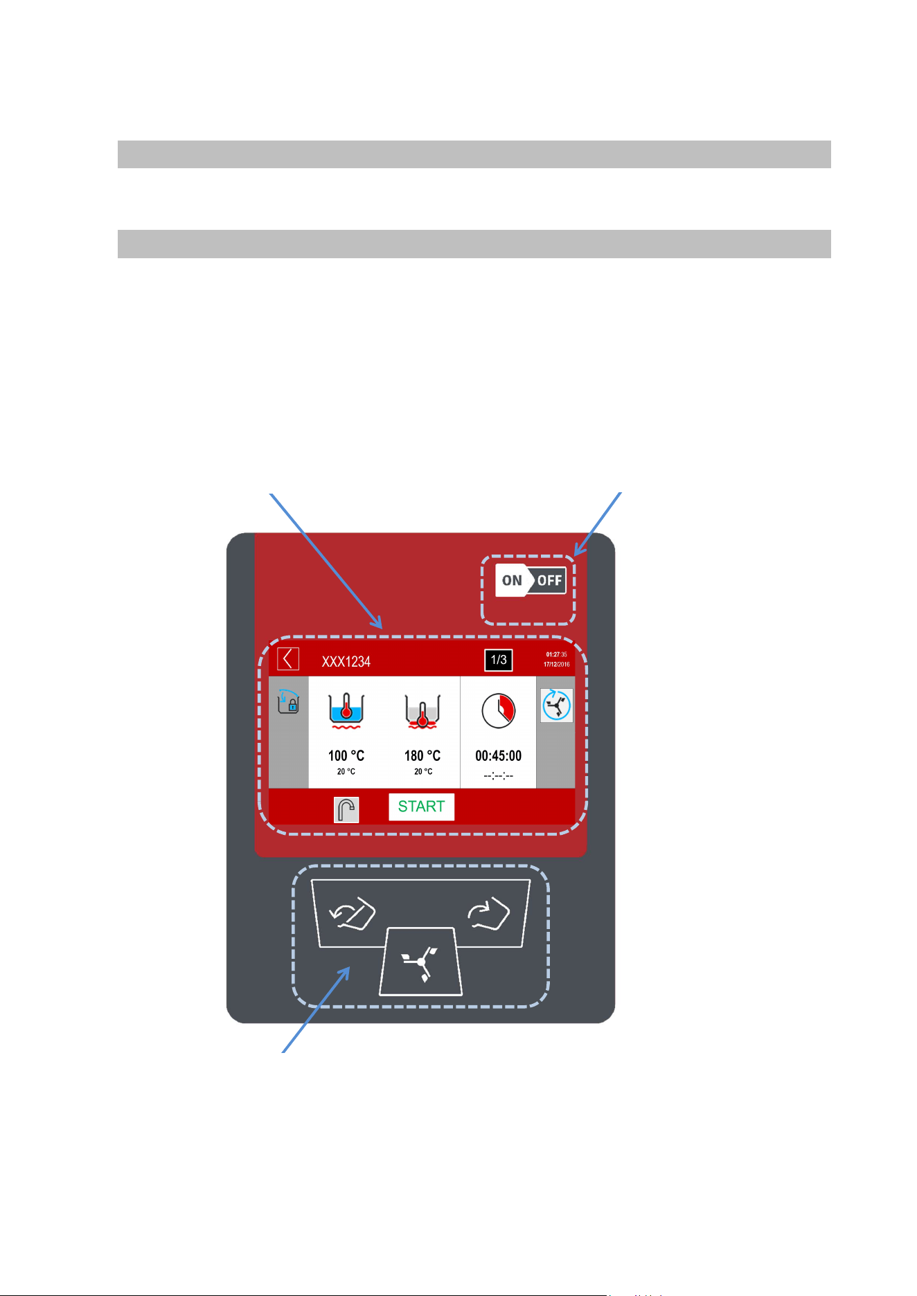
10 TOUCH SCREEN
1-On-off switch
2- 7" TFT resistive display
3- Keypad for movements (mixer, pan)
2- 7" TFT resistive display
1-On-off switch
3- Keypad for movements (mixer, pan)
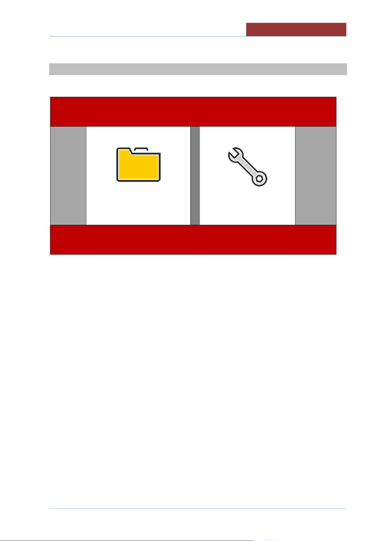
MAIN MENU
01
-
UDBRG_V1
-
DIMU
-
00
-
EN
33
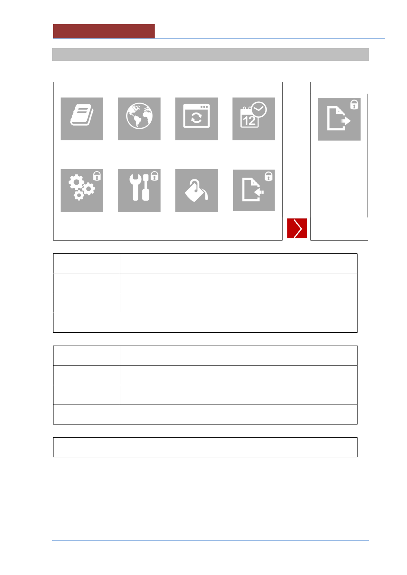
11 MAIN MENU
PROGRAMS
SETTINGS
PROGRAMS
Setting manual cooking parameters
Carrying out manual cooking
Running cooking programs
SETTINGS
Appliance setting-user;
creating-editing cooking programs
language
date-time
firmware update
colors
EXPORT (HACCP data)
Appliance setting - installer/technical assistant;
TEST I/O
Parameter setting (unit of measurement)
Import database
01
-
UDBRG_V1
-
DIMU
-
00
-
EN
SETTINGS MENU
34
12 SETTINGS MENU
PROGRAMS
LANGUAGES
FIRMWARE
DATE
-
HOUR
EXPORT
TEST I/0
PARAMETERS
COLORS
IMPORT
PROGRAMS
Creating-editing cooking programs
LANGUAGES
Language setting
FIRMWARE
Firmware update (from USB)
DATE-HOUR
Current Date and Time setting
TEST I/0
Test I/O board (only with password)
PARAMETERS
Parameter setting (only with password)
COLORS
Screen colour setting
IMPORT
Import database (parameters, cooking, languages, programs) only with
password.
EXPORT
Export (HACCP data).Read the instruction manual dedicated to HACCP.
PROGRAMS MENU
01
-
UDBRG_V1
-
DIMU
-
00
-
EN
35
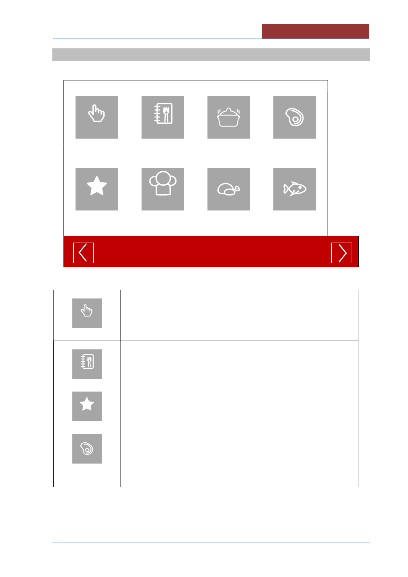
13 PROGRAMS MENU
MANUAL
ALL
SAUCES
MEAT
FAVORITES
CHEF
POULTRY
FISH
MANUAL
Setting manual cooking parameters
Carrying out manual cooking
ALL
FAVORITES
MEAT
ETC
Running cooking programs
01
-
UDBRG_V1
-
DIMU
-
00
-
EN
COOKING LAYOUT
36
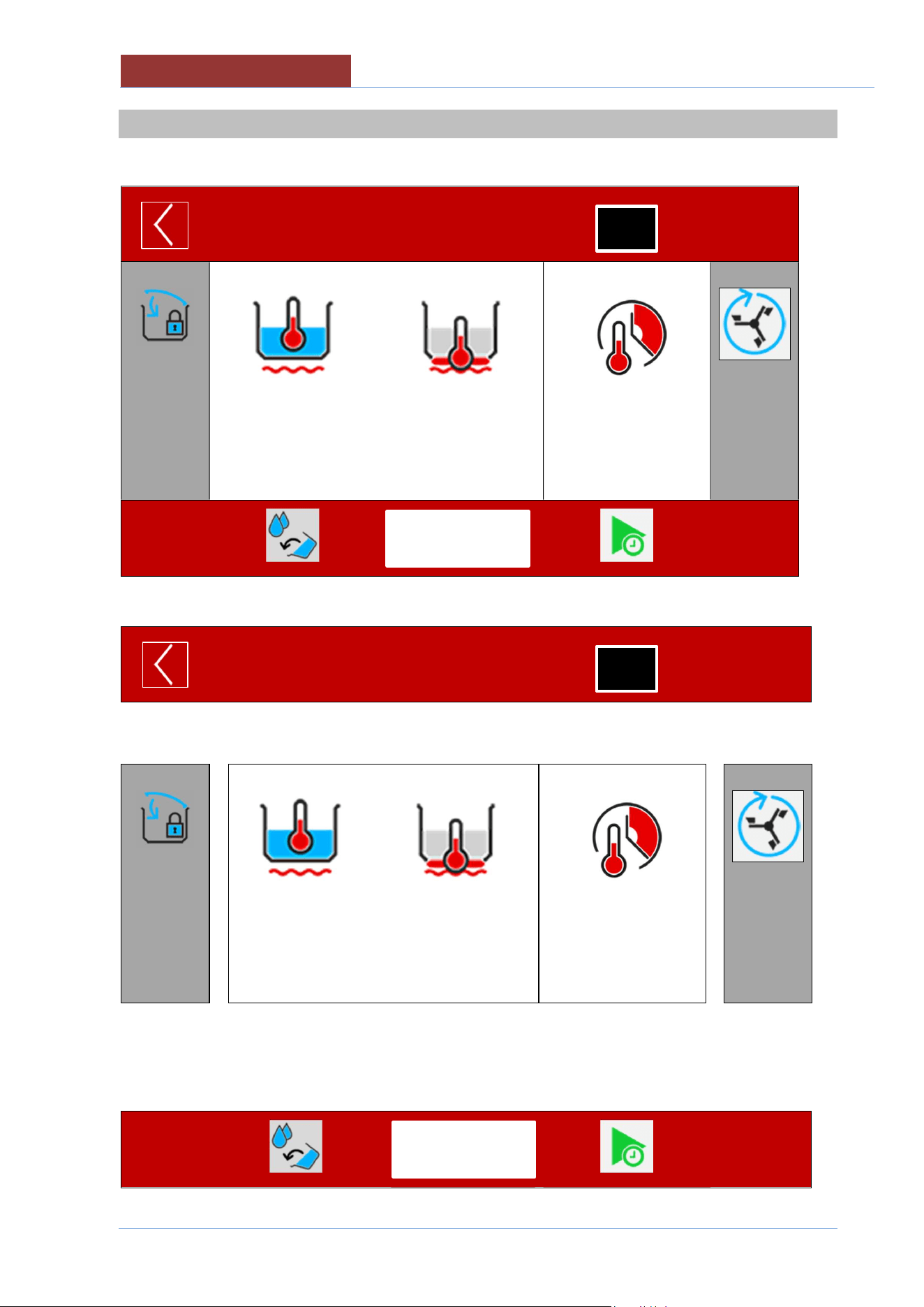
14 COOKING LAYOUT
XXX1234
01:27: 35
17/12/ 2016
100°C
20°C
180°C
20°C
00:45:00
--:--:--
STATUS BAR
XXX1234
01:27: 35
17/12/ 2016
↓ COOKING AREA
_________________________________________________________
100°C
20°C
180°C
20°C
00:45:00
--:--:--
_________
__________
↑ MESSAGE COLUMN FUNCTION COLUMN ↑
FUNCTION BAR
1/3
START
1/3
START
COOKING LAYOUT
01
-
UDBRG_V1
-
DIMU
-
00
-
EN
37
14.1 STATUS BAR
1
2
3 4
5
XXX1234
01:27: 35
17/12/ 2016
1
STAND-BY/RETURN KEY; 3 sec → HOME
↓
COOKING/PROGRAM IN PROGRESS.
↓
COOKING/PROGRAM IN PROGRESS (PAUSED) AWAITING ACTION.
2
XXX1234
Name of cooking program selected
3
PROGRAM IN THE LIST OF FAVOURITES (not present in manual cooking)
4
PROGRAM PHASE IN PROGRESS (not present in manual cooking)
5
01:27: 35
17/12/ 2016
CURRENT TIME AND DATE
I I
01
-
UDBRG_V1
-
DIMU
-
00
-
EN
COOKING LAYOUT
38
14.2 COOKING AREA
COOKING METHOD>
SETPOINT >
VALUE MEASURED>
100°C
20°C
180°C
20°C
00:45:00
--:--:--
< TIME TYPE
< SETPOINT
< COUNTDOWN
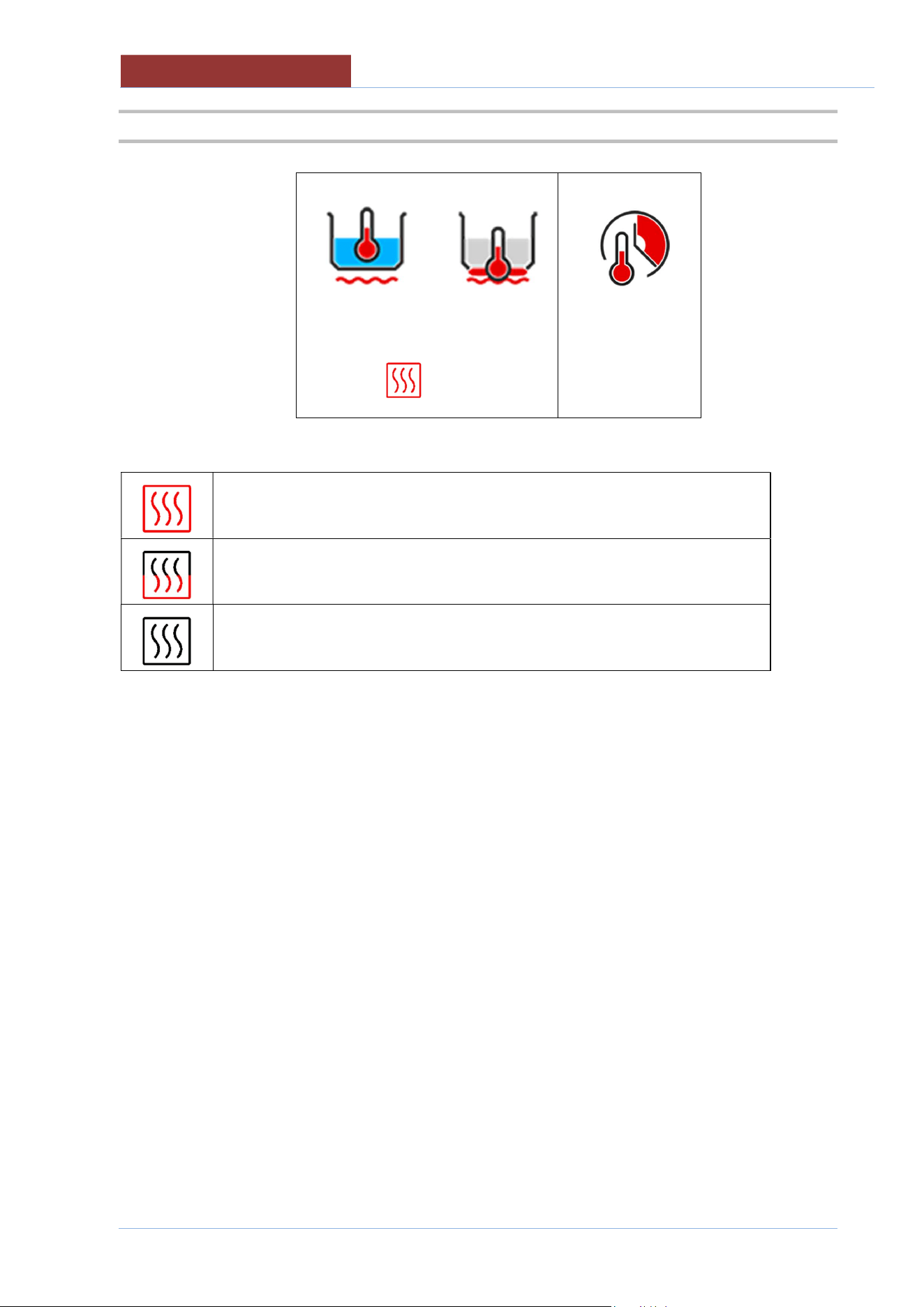
HEATING IN OPERATION
MINIMUM HEATING
HEATING OFF AS SETPOINT REACHED OR FOR WAITING (L
COLUMN ICONS)
COOKING LAYOUT
01
-
UDBRG_V1
-
DIMU
-
00
-
EN
39
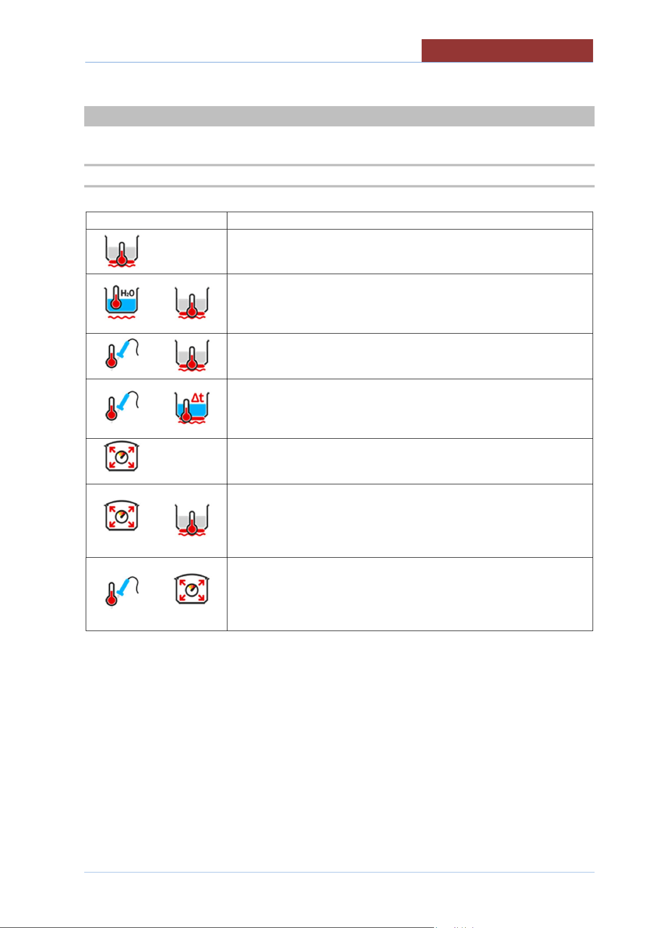
14.2.1 COOKING ICONS (MEANING)
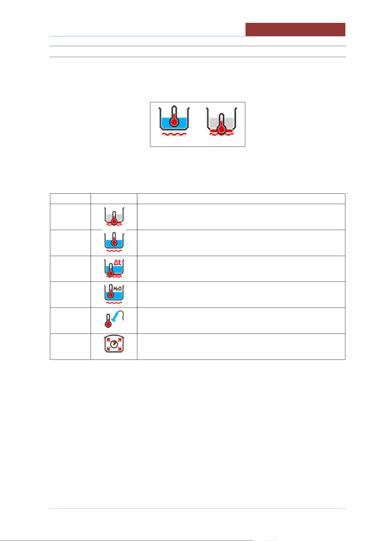
Left or central icon: main control (when the SETPOINT is reached, heating stops and the countdown of
the cooking time starts)
↓
↑
Right icon: secondary control (when the SETPOINT is reached,
the heating stops)
Name
Icon
Description
Temperature at bottom
Temperature in the pan
Δ Temperature between bottom and main temperature
H2O temperature in the pan
Core probe temperature
Pressure cooking (SETPOINT not settable)
01
-
UDBRG_V1
-
DIMU
-
00
-
EN
COOKING LAYOUT
40
14.3 MESSAGE COLUMN (L)
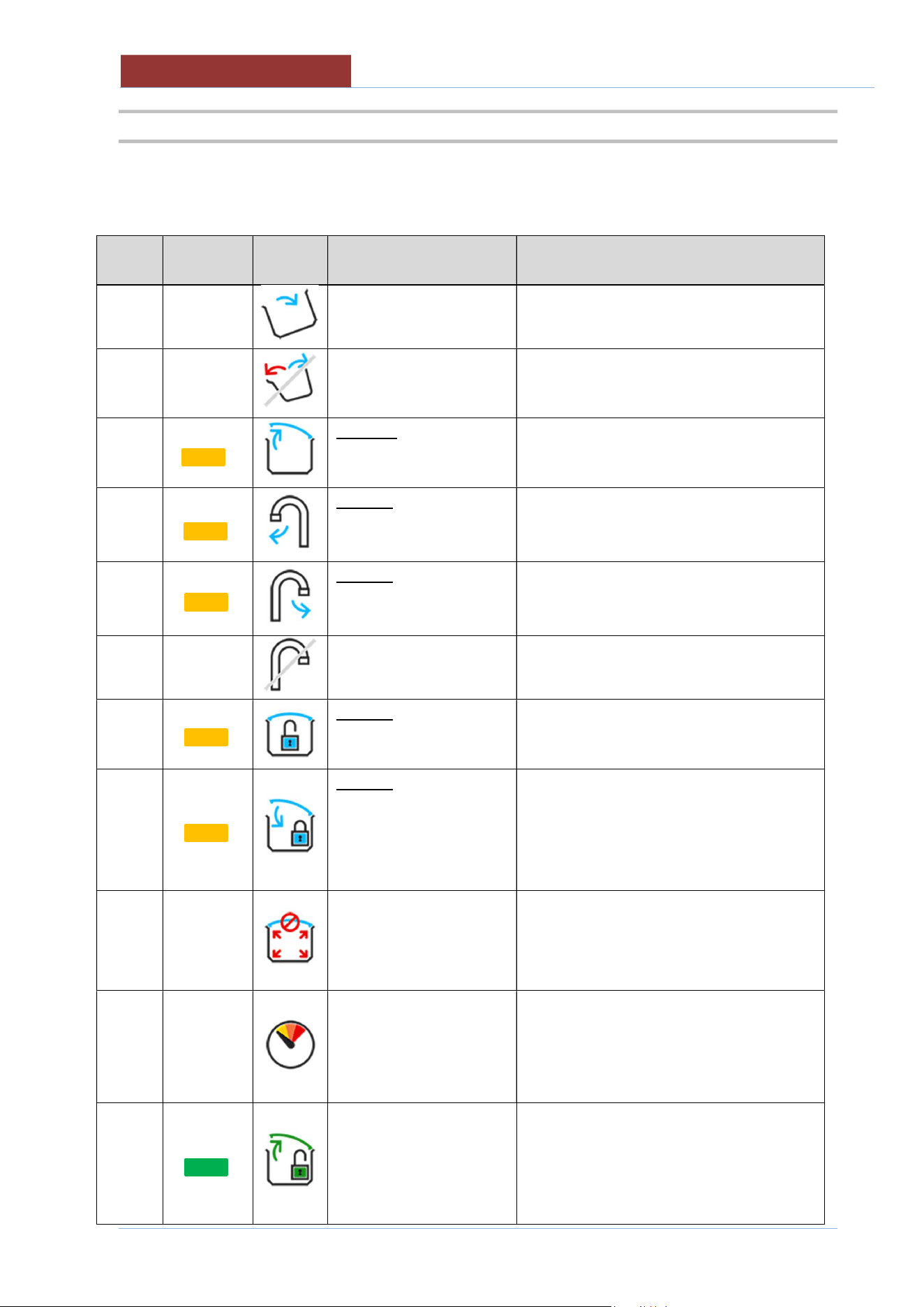
INFORMATION AND REQUESTS INDICATOR L COLUMN
buzzer
Light
Indicator
Icon Description Behaviour
no no
Pan out of position (for
cooking)
Icon present when pan out of position
no no
Pan movement not
allowed
Icon present only when you want to
perform a pan movement in an
unauthorised phase.
B
Request to completely
open the lid (for pan
movement)
Icon present only when you want to move
the pan and the lid is not completely open.
B
Request to turn the tap
(for pan movement)
Attn. alternate icon
Icon present only when you want to move
the pan and the tap is not completely
turned (towards the outside of the pan).
B
Request to turn the tap
(to fill pan with H2O)
Attn. alternate icon
Icon present only when you want to fill pan
with H2O and the tap is not completely
turned (towards the pan).
no no
Not allowed to fill pan
with H2O
Icon present only when you want to fill pan
with H2O during an unauthorised phase.
B
Request to unlock the lid
(cooking not allowed)
Icon only present when the lid is closed
(locked in pressure mode) during NON-
pressure cooking.
B
Request to close and
block the lid (pressure
cooking)
Attn. animated icon
Icon only present when the lid is NOT
closed (locked in pressure mode) during
pressure cooking.
no no
Do not open the lid
(pressurised pan!!)
Attn. alternate icon
Icon present when the machine is
pressurised.
no no
Steam condensation -
Reduction in cooking
pressure
Icon present at the end of a pressure
cooking. Indicates that steam is being
condensed to reduce the pressure in the
cooking pan and allow the lid to be
opened.
no
End of pressure cooking.
It is possible to unlock
and open the lid
Icon present at the end of a pressure
cooking.
COOKING LAYOUT
01
-
UDBRG_V1
-
DIMU
-
00
-
EN
41
buzzer Light
Indicator
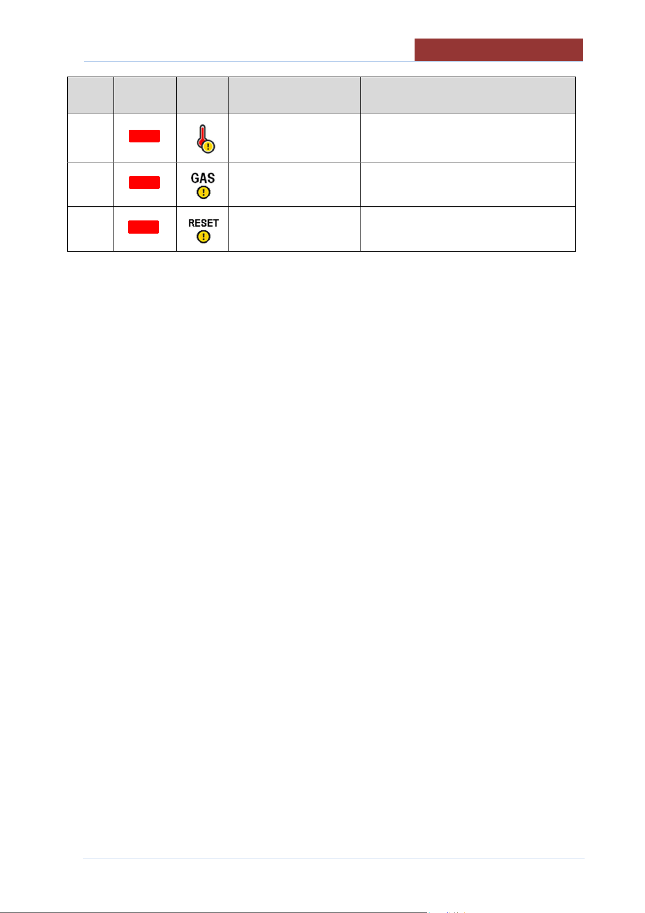
Icon Description Behaviour
A
Safety thermostat has
been triggered
Icon present when the safety thermostat
has been triggered. To reset the alarm,
restore the safety thermostat.
A
Insufficient gas pressure Icon present when gas pressure switch
has been triggered.
A
Gas central unit reset Icon present due to interruption in the gas
central unit
01
-
UDBRG_V1
-
DIMU
-
00
-
EN
COOKING LAYOUT
42
14.4 FUNCTION BAR
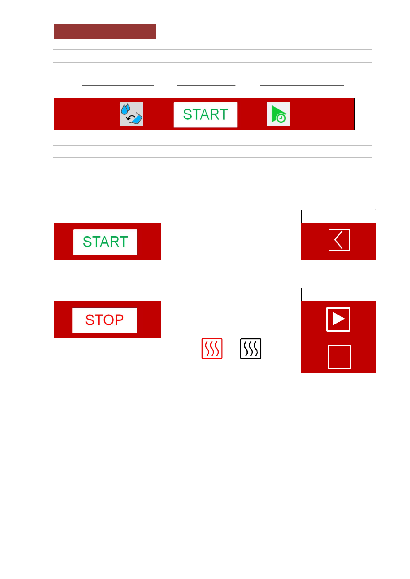
EXTRA KEY (functions) START/STOP KEY DELAYED COOKING KEY
↓ ↓ ↓
14.4.1 START-STOP KEY FOR RUNNING PROGRAMS
Attention: the START/STOP key indicates the action that will be performed by pressing the key!
The machine status is indicated by the icon on the top left
With key presence Machine status
icon on the top left
Machine in stand-by.
Pressing the START key starts the program and the START key becomes the STOP.
With key presence Machine status
icon on the top left
Program running.
or
I I
COOKING LAYOUT
01
-
UDBRG_V1
-
DIMU
-
00
-
EN
43
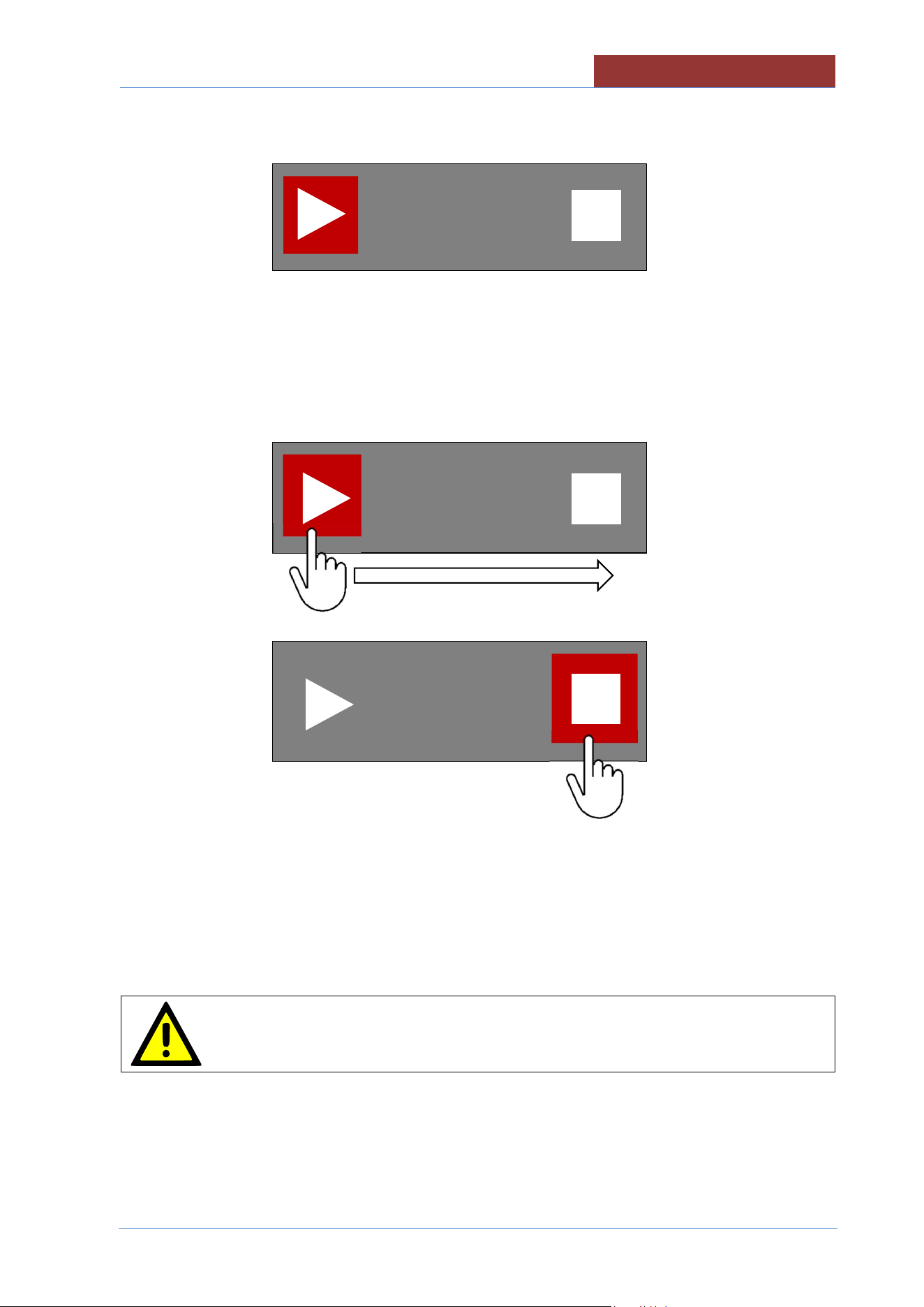
To avoid accidentally stopping the cooking program in progress, press the STOP key and the following
screen appears:
If the STOP key has been pressed incorrectly, wait approximately 5 seconds and you return to the
program in progress.
If instead you want to stop the program, slide the coloured square from the triangle to the square and
release the key.
The STOP key becomes START.
Respect a 5 minute complete shuttoff period before the appliance is relighted.
01
-
UDBRG_V1
-
DIMU
-
00
-
EN
COOKING LAYOUT
44
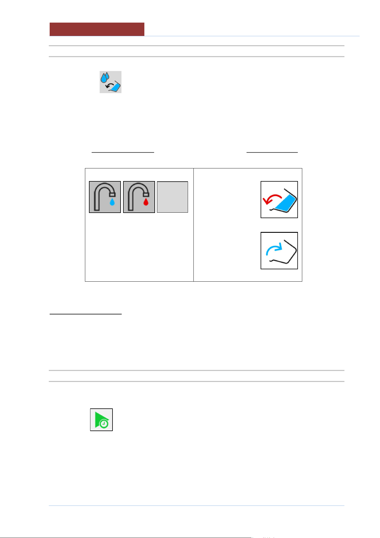
14.4.2 EXTRA KEY
Pressing the key it is possible to access the following functions: H2O loading into the vessel,
vessel tilting and motorized vessel discharge (optional)
FILL PAN WITH H2O PAN MOVEMENT
↓ ↓
0 Lt
0 Lt
FILLING PAN WITH H2O
LITRE-COUNTER DEVICE ACCURACY +/- 2% AND MAX H2O TEMPERATURE
140°F (60°C)
MAX LITRES = PAN CAPACITY
14.4.3 COOKING WITH DELAY TIMER KEY
Press the key to access the settings for cooking with delay timer.
START
COOKING METHODS IN DETAIL
01
-
UDBRG_V1
-
DIMU
-
00
-
EN
45
15 COOKING METHODS IN DETAIL
15.1 COOKING
Icon
Description
For braising that requires a temperature up to 250°C; the temperature regulation
is controlled by the sensor (PT1000) located on the bottom of the pan
For all cooking in water that requires a maximum temperature of 100°C; the
temperature regulation is controlled by the sensor (PT1000) located inside the
pan, in contact with the product, and by the sensor placed on the bottom of the
pan
For cooking that requires accurate regulation and monitoring of the temperature
at the core of the product; the temperature regulation is controlled by the probe
(PT1000) placed inside the product.
For gentle and slow cooking that require accurate regulation and monitoring of
the temperature at the core of the product, the temperature regulation is
controlled by the probe place inside the product and the difference set between
the bottom and the inside of the product.
For different cooking methods that require faster processes; the temperature is
controlled by the pressure switches, the maximum attainable pressure is 0.45
bar (mod.029 038) 0.30 bar (mod.048).
For different types of cooking t
hat require faster processing
and control of the
temperature of the bottom (particularly dry products); the temperature regulation
is controlled by the pressure switches and by the sensor located on the bottom
of the pan. The maximum pressure that can be reached is 0.45 bar (mod.029
038) 0.30 bar (mod.048).
For cooking that requires accurate regulation and monitoring of the temperature
at the core of the product during pressure cooking; the temperature regulation is
controlled by the probe placed in the product and by intervention of the pressure
switches, the maximum pressure that can be reached is 0.45 (mod.029 038)
0.30 bar (mod.048).
01
-
UDBRG_V1
-
DIMU
-
00
-
EN
SETTING SETPOINT PARAMETERS
46
16 SETTING SETPOINT PARAMETERS
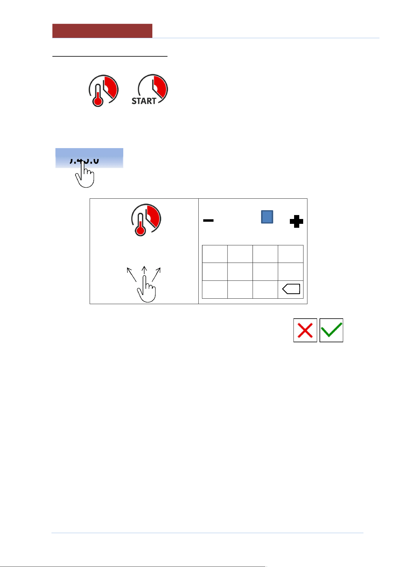
16.1 SETTING SETPOINT VALUES WITH THE KEYPAD
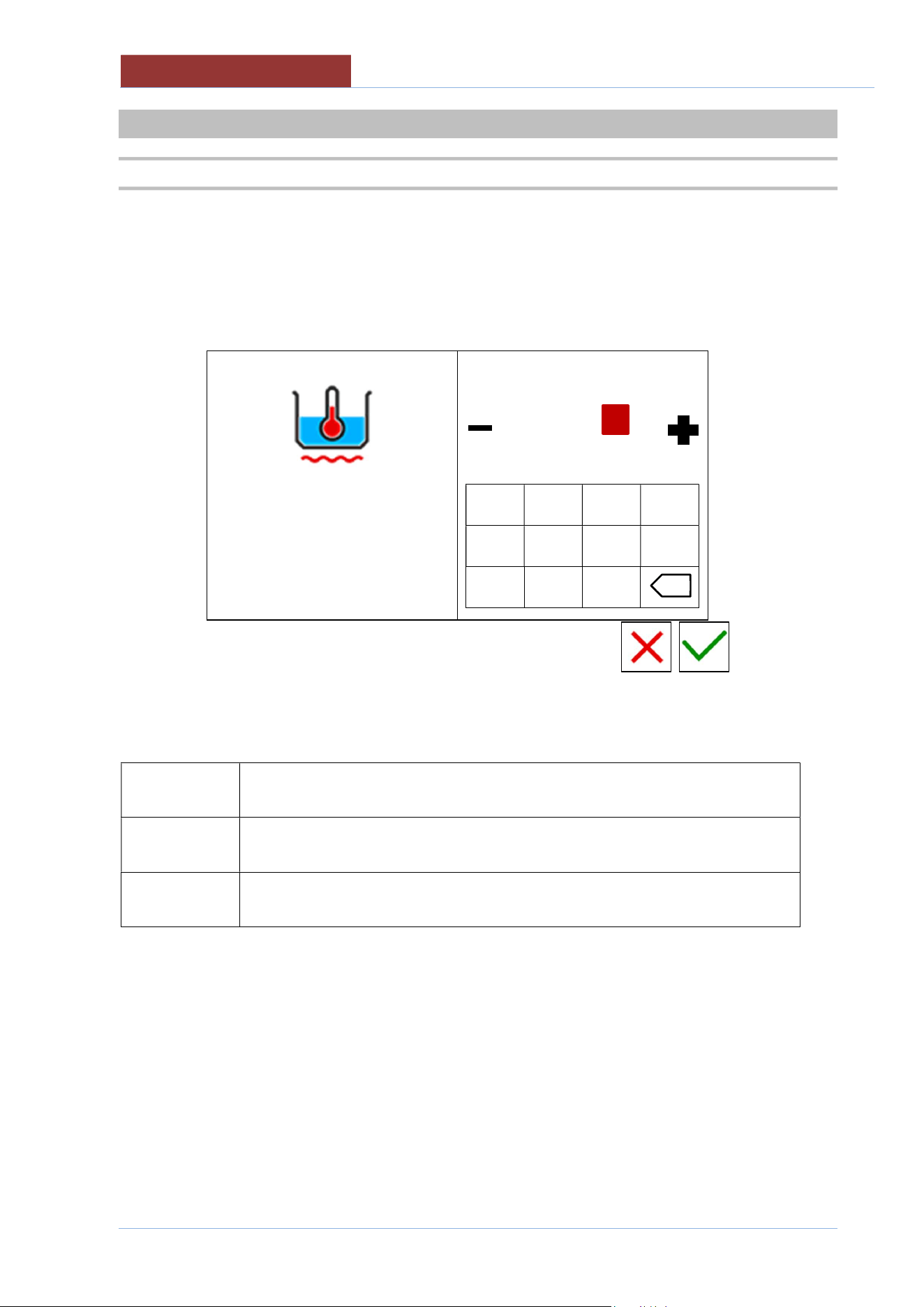
The following screen appears when setting any setpoint value:
left column: parameter of which you are changing the setpoint value.
right column: keypad + cursor for changing the setpoint.
100°C
20°C 120°C
min max
-------------------
1 2 3 4
5 6 7 8
- 9 0
Fields in the left column have the following meanings:
100°C
RED VALUE: VALUE OF WHICH YOUR ARE CHANGING THE SET
20°C
min
MINIMUM VALUE SETTABLE
120°C
max
MAXIMUM VALUE SETTABLE
x
SETTING SETPOINT PARAMETERS
01
-
UDBRG_V1
-
DIMU
-
00
-
EN
47
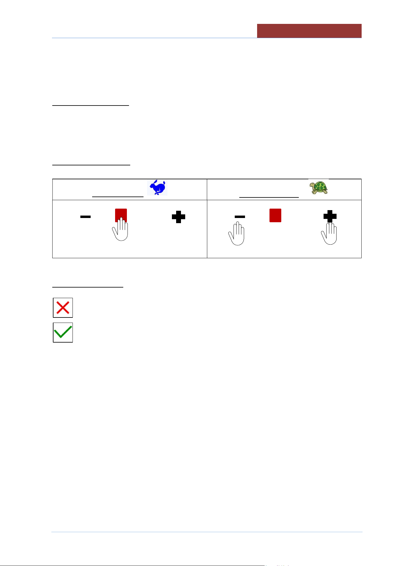
The values in the right column will be changed as follows:
SETTING WITH KEYPAD
TYPE THE DESIRED VALUE.
ATTENTION : THE VALUE MUST BE BETWEEN min AND max!
SETTING WITH CURSOR
QUICK SETTING
PRECISE SETTING
------------------
← →
------------------
EXIT FROM SETTINGS
Exit without confirming settings key
Exit confirming settings key
01
-
UDBRG_V1
-
DIMU
-
00
-
EN
COOKING PARAMETERS SETTING
48
17 COOKING PARAMETERS SETTING
The setting of the following parameters can only be made from the menu:
1. PROGRAMS + MANUAL
2. SETTINGS + PROGRAMS
17.1 SETTING COOKING METHOD AND TEMPERATURE
100°C
20°C
180°C
20°C
00:45:00
--:--:--
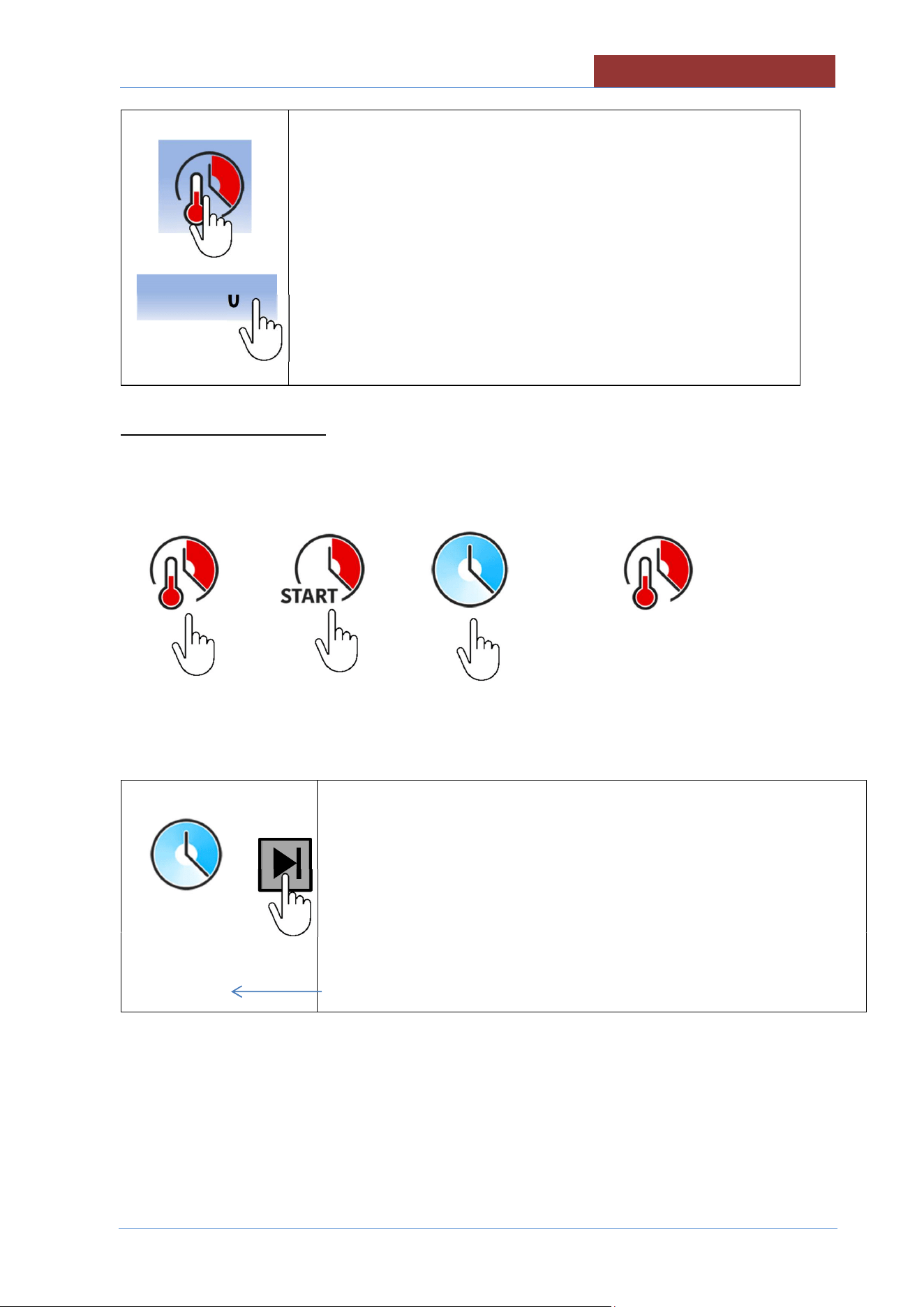
AREA HIGHLIGHTED = SELECTION/SETTINGS
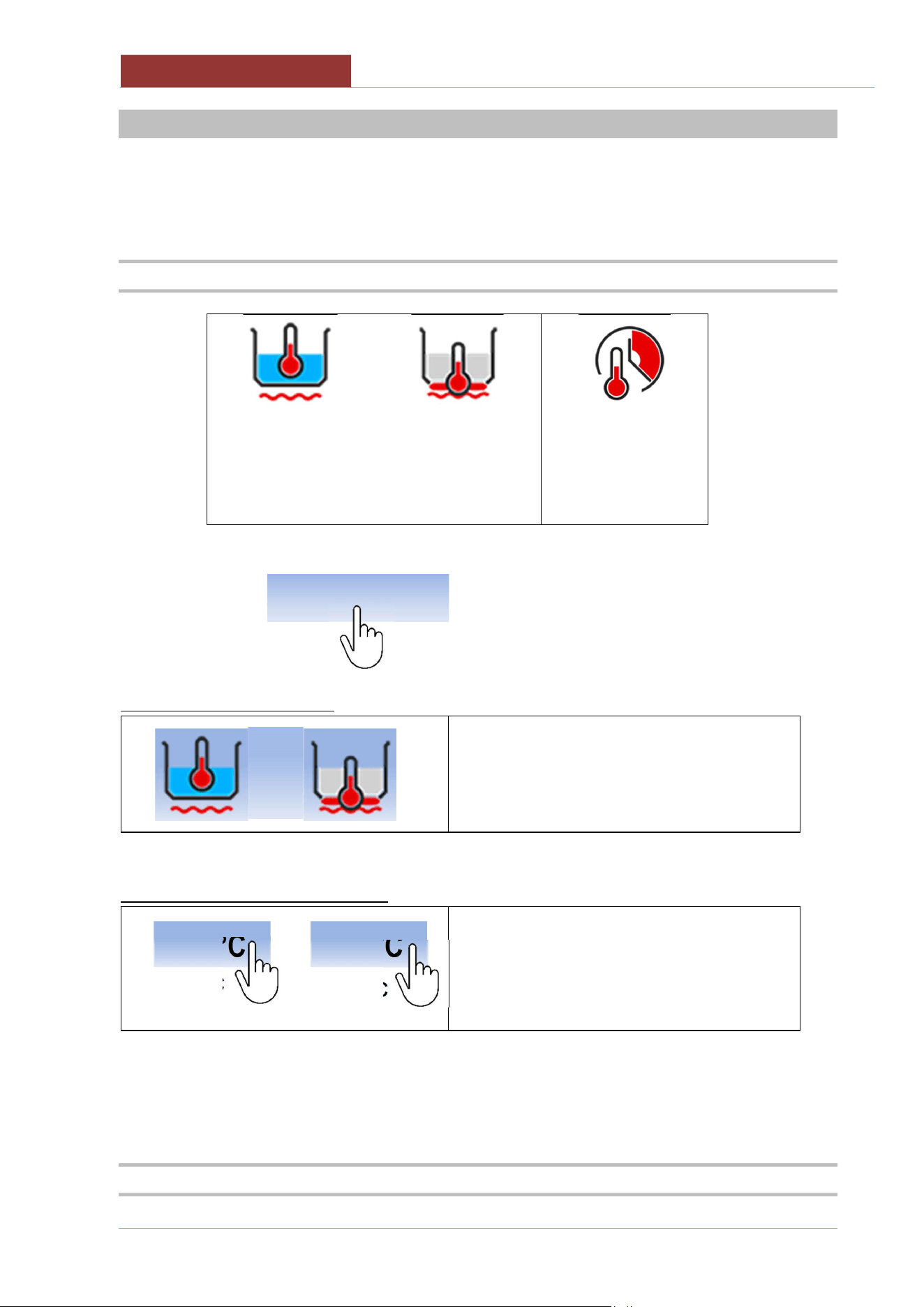
SETTING COOKING METHOD
SELECTING COOKING METHOD (see Cooking
methods in detail)
SETTING TEMPERATURE SETPOINT
20 °C
20 °C
< COOKING SETPOINT (see SETPOINT)
< TEMPERATURE DISPLAY
SET THE SETPOINT AS DESCRIBED IN THE CHAPTER
17.2 SETTING COOKING TIME
18
0 °C
10
0 °C
COOKING PARAMETERS SETTING
01
-
UDBRG_V1
-
DIMU
-
00
-
EN
49
--:--:--
SELECTING COOKING TIME
< COOKING TIME SETPOINT (see SETPOINT)
< COOKING TIME COUNTDOWN
SELECTING COOKING TIME
Cooking time Cooking time Infinite time
(at setpoint °C) (immediate)
→ → →
ATTENTION: WHEN SELECTING THE INFINITE TIME, PRESS THE KEY INDICATED BELOW TO
TERMINATE THE PROGRAM IN PROGRESS.
NOTE:
The time elapsed since the beginning of the phase is indicated on the bottom row.
--:--:--
00:04:31
00:45:00
01
-
UDBRG_V1
-
DIMU
-
00
-
EN
COOKING PARAMETERS SETTING
50
SETTING COOKING TIME SETPOINT
Only with
↓
00:45:00
---------------
1 2 3 4
5 6 7 8
- 9 0
HH:MM:SS
HH: 99 max; MM: 59 max; SS: 59 max
00:45:00
x
CREATING PROGRAMS (MULTI
-
PHASE)
01
-
UDBRG_V1
-
DIMU
-
00
-
EN
51
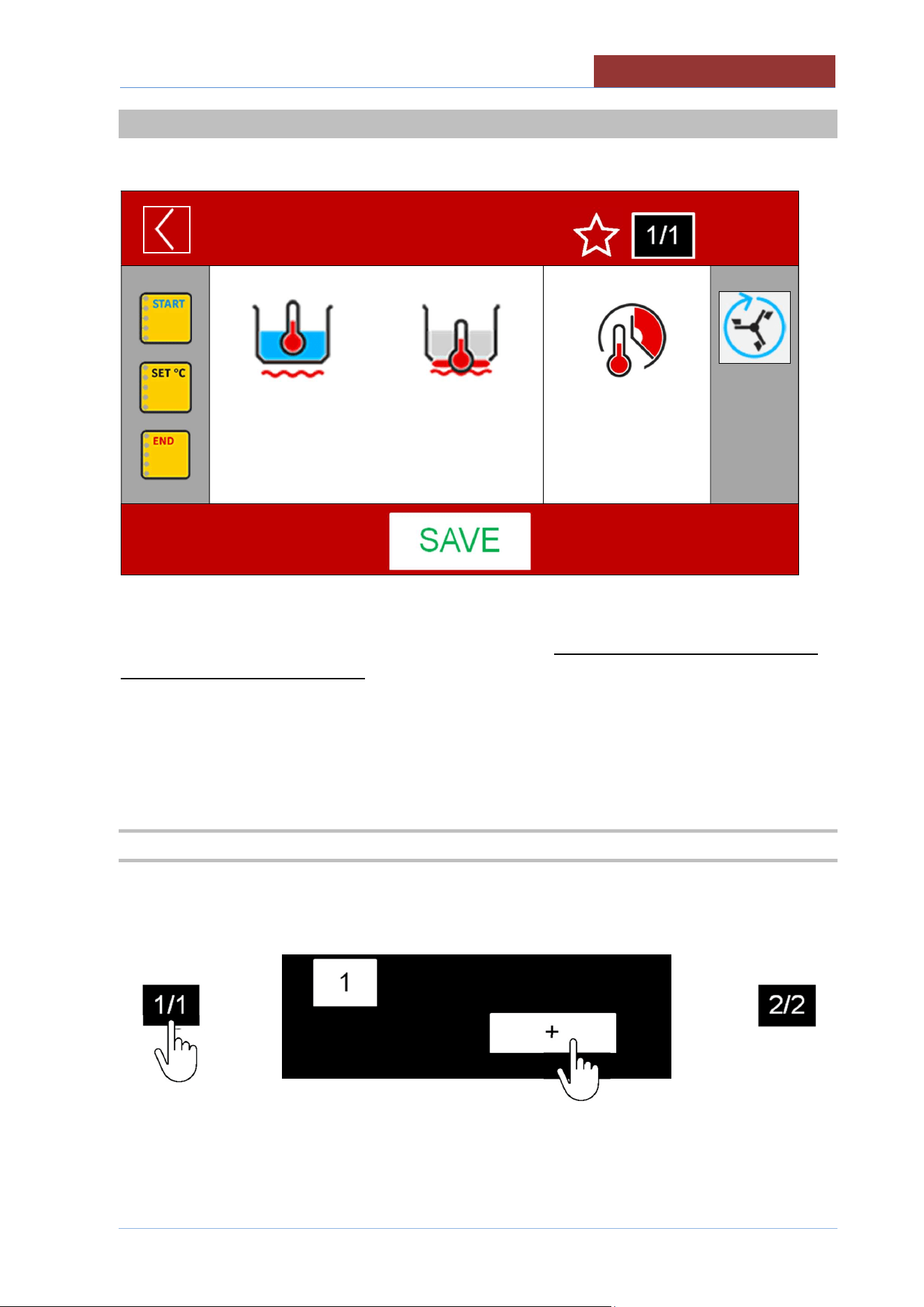
18 CREATING PROGRAMS (MULTI-PHASE)
FROM SETTINGS> PROGRAMS> NEW
NEW PROGRAM
01:27: 35
17/12/ 2016
100°C
20°C
180°C
20°C
00:45:00
--:--:--
A PROGRAM CAN CONSIST OF 20 PHASES.
THE PARAMETERS ARE CONSTANT WITHIN EACH PHASE. IF A SINGLE VALUE CHANGES, YOU
NEED TO CREATE A NEW PHASE!
THE CREATION OF THE PHASE CONSISTS OF ENTERING THE COOKING METHOD, COOKING
TIMES, MIXER FUNCTIONS AND WALL HEATING.
IT IS ALSO POSSIBLE TO ENTER (IN EVERY PHASE) 3 MESSAGES PRESENT IN THE LEFT
COLUMN. (SEE MESSAGE SETTINGS)
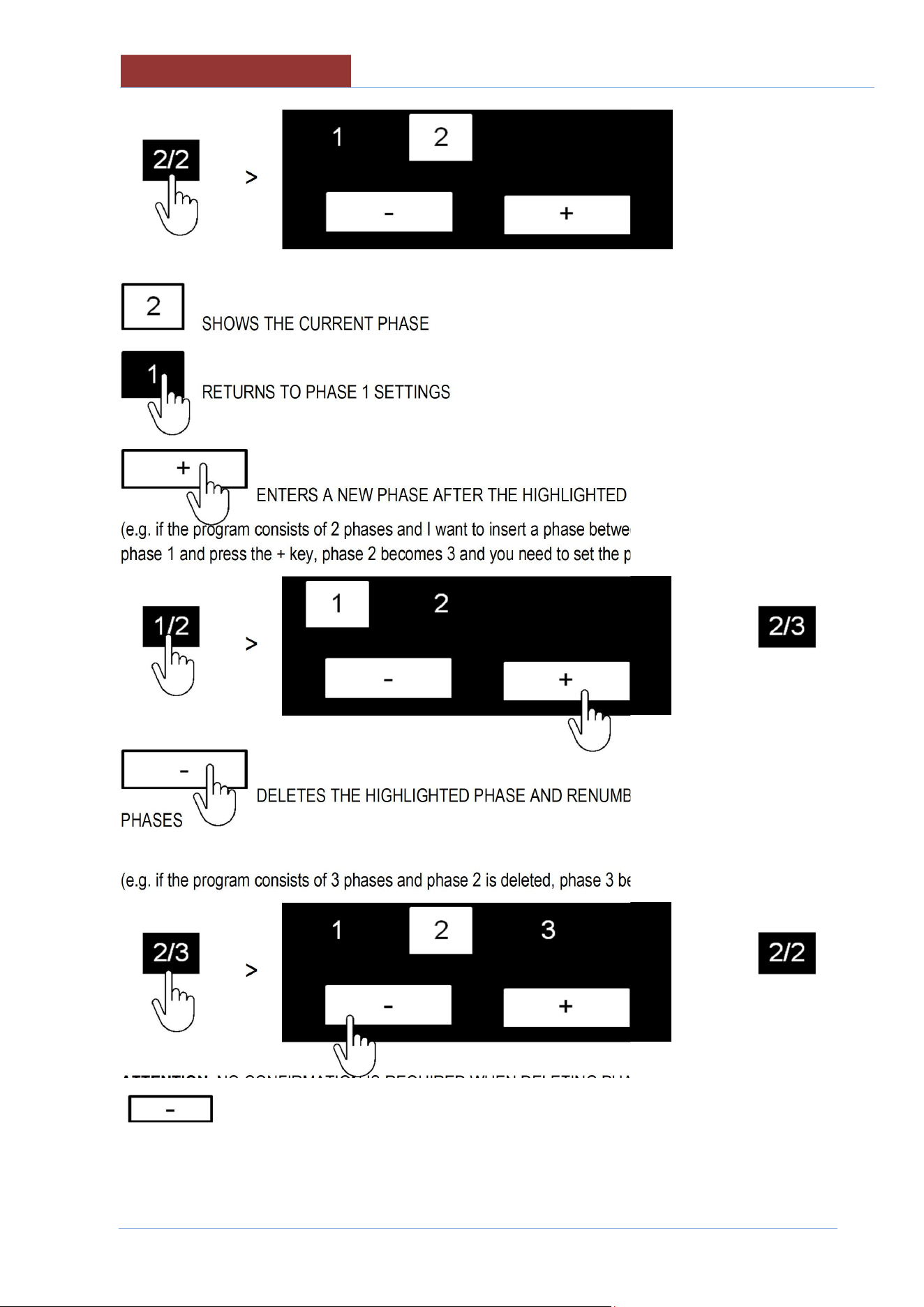
18.1 CREATING/DELETING PHASES
ONCE THE PARAMETERS OF PHASE 1 ARE SET, YOU CAN THEN ADD PHASE 2:
>
>
AFTER HAVING ADDED AND SET THE PARAMETERS OF PHASE 2, PRESSING ON THE
PHASE/PHASE FIELD DISPLAYS THE FOLLOWING SCREEN:
01
-
UDBRG_V1
-
DIMU
-
00
-
EN
CREATING PROGRAMS (MULTI
-
PHASE)
52
>
SHOWS THE CURRENT PHASE
RETURNS TO PHASE 1 SETTINGS
ENTERS A NEW PHASE AFTER THE HIGHLIGHTED PHASE
(e.g. if the program consists of 2 phases and I want to insert a phase between 1 and 2, I have to select
phase 1 and press the + key, phase 2 becomes 3 and you need to set the parameters for phase 2).
>
>
DELETES THE HIGHLIGHTED PHASE AND RENUMBERS THE FOLLOWING
PHASES
(e.g. if the program consists of 3 phases and phase 2 is deleted, phase 3 becomes 2)
>
>
ATTENTION: NO CONFIRMATION IS REQUIRED WHEN DELETING PHASES! PRESSING THE KEY
IMMEDIATELY DELETES THE CURRENT PHASE!
PHASE 1 CAN NOT BE DELETED!
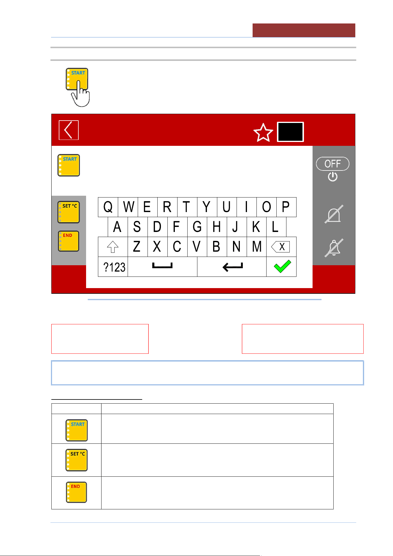
CREATING PROGRAMS (MULTI
-
PHASE)
01
-
UDBRG_V1
-
DIMU
-
00
-
EN
53
18.2 MESSAGE SETTINGS
The following screen appears when selecting the message icon:
NEW PROGRAM
01:27:35
17/12/2016
______
↑
_______
↑
MESSAGE SELECTION KEYS
↑
MESSAGE SETTINGS KEYS
MESSAGE WRITING AREA
MESSAGE SELECTION KEYS
Icon
Description
MESSAGE AT THE BEGINNING OF THE PHASE
MESSAGE ON REACHING SETPOINT
MESSAGE AT THE END OF THE PHASE
1/1
01
-
UDBRG_V1
-
DIMU
-
00
-
EN
CREATING PROGRAMS (MULTI
-
PHASE)
54
MESSAGE SETTINGS KEYS
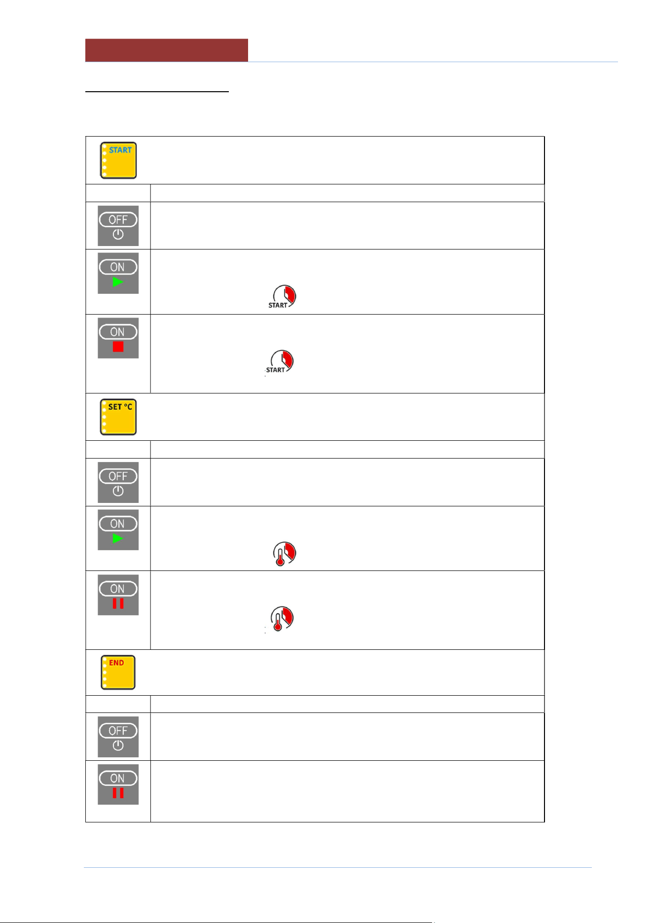
THE KEY ON THE TOP RIGHT TAKES ON THE FOLLOWING FUNCTIONS SPECIFIED IN RELATION
TO THE SELECTED MESSAGE (START; SET °C: END)
START MESSAGE
Key
Behaviour when program running
No message appears
The message appears
The heating starts at "ON"
If the time is set
, the countdown begins
The message appears
The heating stays "OFF" until you reply to the message
If the time is set , the countdown begins when you reply to the
message.
MESSAGE ON REACHING SETPOINT
Key
Behaviour when program running
No message appears
The message appears
Heating keeps the SETPOINT
If the time is set , the countdown begins
The message appears
Heating keeps the SETPOINT
If the time is set , the countdown begins when you reply to the
message.
END OF PHASE MESSAGE
Key
Behaviour when program running
No message appears
The message appears
Heating keeps the SETPOINT
When the countdown has ended, it is possible to increase the cooking time or
move on to the next phase.
CREATING PROGRAMS (MULTI
-
PHASE)
01
-
UDBRG_V1
-
DIMU
-
00
-
EN
55
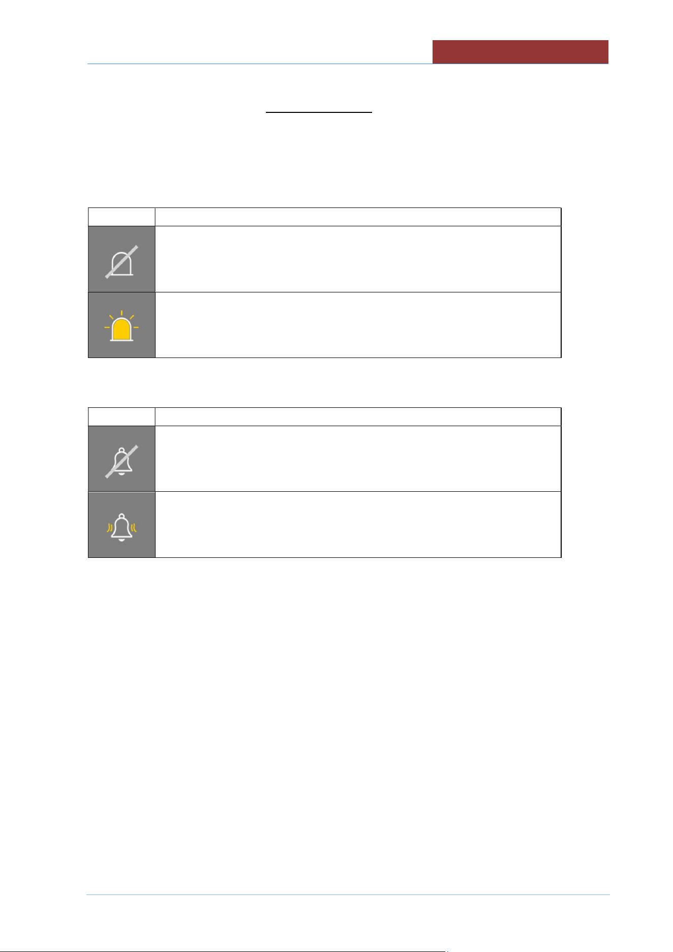
ATTENTION : IF THE MESSAGE IS SET TO OFF, ALL THE SETTINGS DESCRIBED BELOW
(FLASHING, BUZZER, AND TEXT) WILL NOT APPEAR WHEN THE PROGRAM IS RUNNING!
THE FOLLOWING KEYS HAVE THE SAME FUNCTIONS FOR ALL MESSAGES (START; SET °C;
END)
Flashing (optional)
Right key
Behaviour when program running
Flashing not enabled
When the message appears, the flashing light also switches on.
(message frame flashing or external flashing optional)
Buzzer
Right key
Behaviour when program running
Buzzer not enabled
When the message appears, the buzzer sounds
01
-
UDBRG_V1
-
DIMU
-
00
-
EN
CREATING PROGRAMS (MULTI
-
PHASE)
56
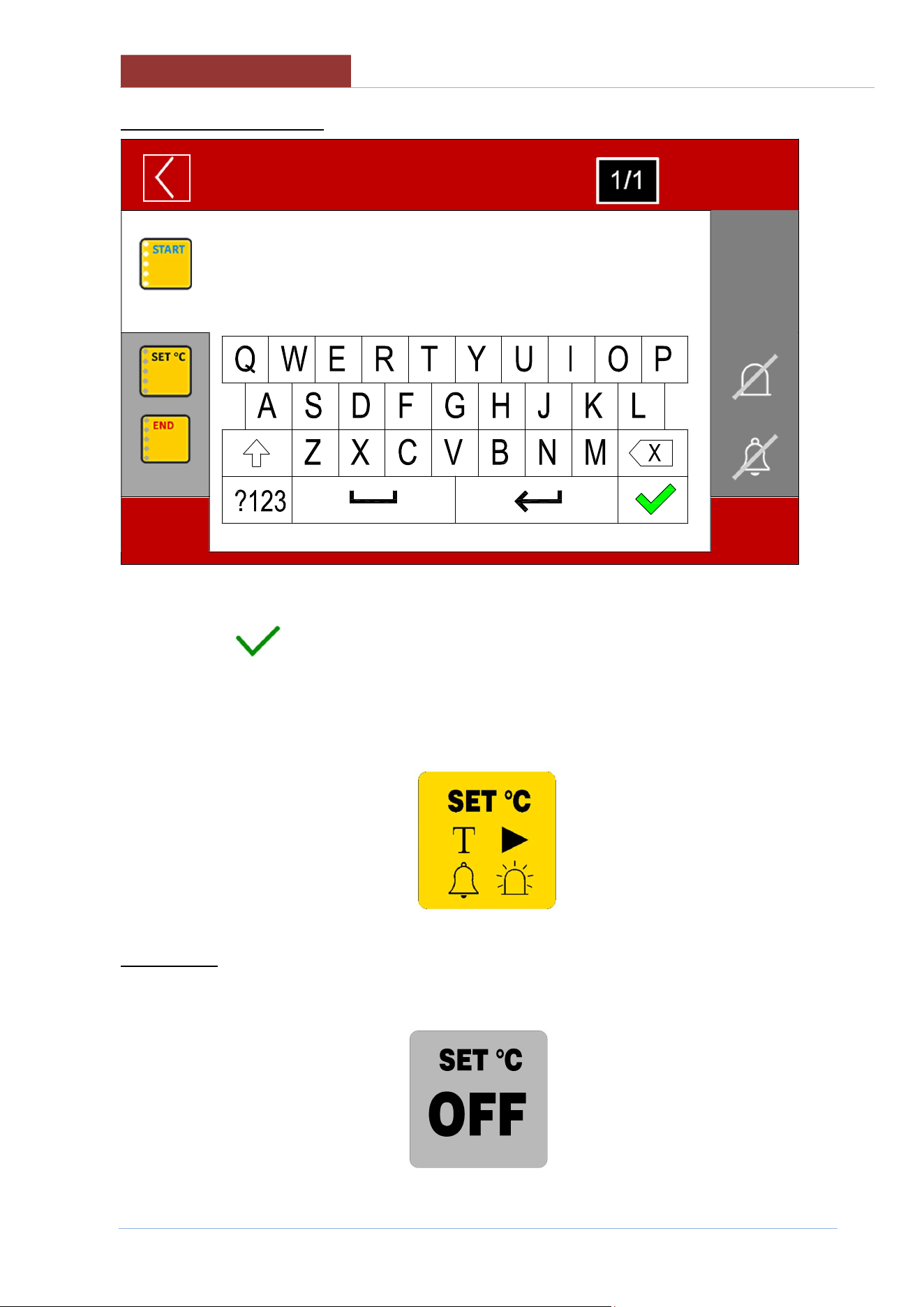
ENTERING MESSAGE TEXT
NEW PROGRAM
01:27: 35
17/12/ 2016
USE THE KEYPAD TO ENTER A DESCRIPTIVE TEXT (MAX 200 CHARACTERS) AND CONFIRM
WITH THE KEY .
AFTER HAVING SET ALL THE VARIABLES WITHIN THE MESSAGE, THE RELATED MESSAGE
ICON WILL SHOW WITHIN ALL THE SYMBOLS THAT SUMMARISE THE SETTINGS OF THE
MESSAGE ITSELF.
TEXT PRESENT>
BUZZER ENABLED>
< ACTION TYPE
< FLASHING ENABLED
ATTENTION: IF THE MESSAGE IS IN "OFF", IT APPEARS ON A GREY BACKGROUND.
ANY SETTINGS (TEXT, BUZZER, FLASHING) WILL NOT BE CANCELLED FROM MESSAGE
SETTING!
CREATING PROGRAMS (MULTI
-
PHASE)
01
-
UDBRG_V1
-
DIMU
-
00
-
EN
57
18.3 SAVING A PROGRAM
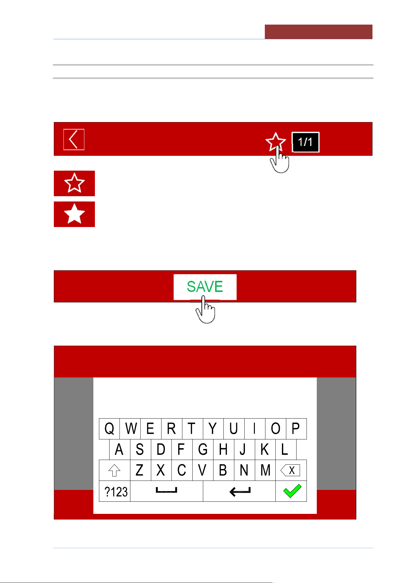
IF YOU WANT TO ADD THE PROGRAM TO THE LIST OF FAVOURITES, PRESS THE "STAR"
SYMBOL.
NEW PROGRAM
01:27: 35
17/12/ 2016
Program NOT added to favourites
Program added to favourites
PRESS THE "SAVE" BUTTON
THE KEYPAD APPEARS TO ENTER THE PROGRAM NAME.
PROGRAM NAME
01:27: 35
17/12/ 2016
01
-
UDBRG_V1
-
DIMU
-
00
-
EN
CREATING PROGRAMS (MULTI
-
PHASE)
58
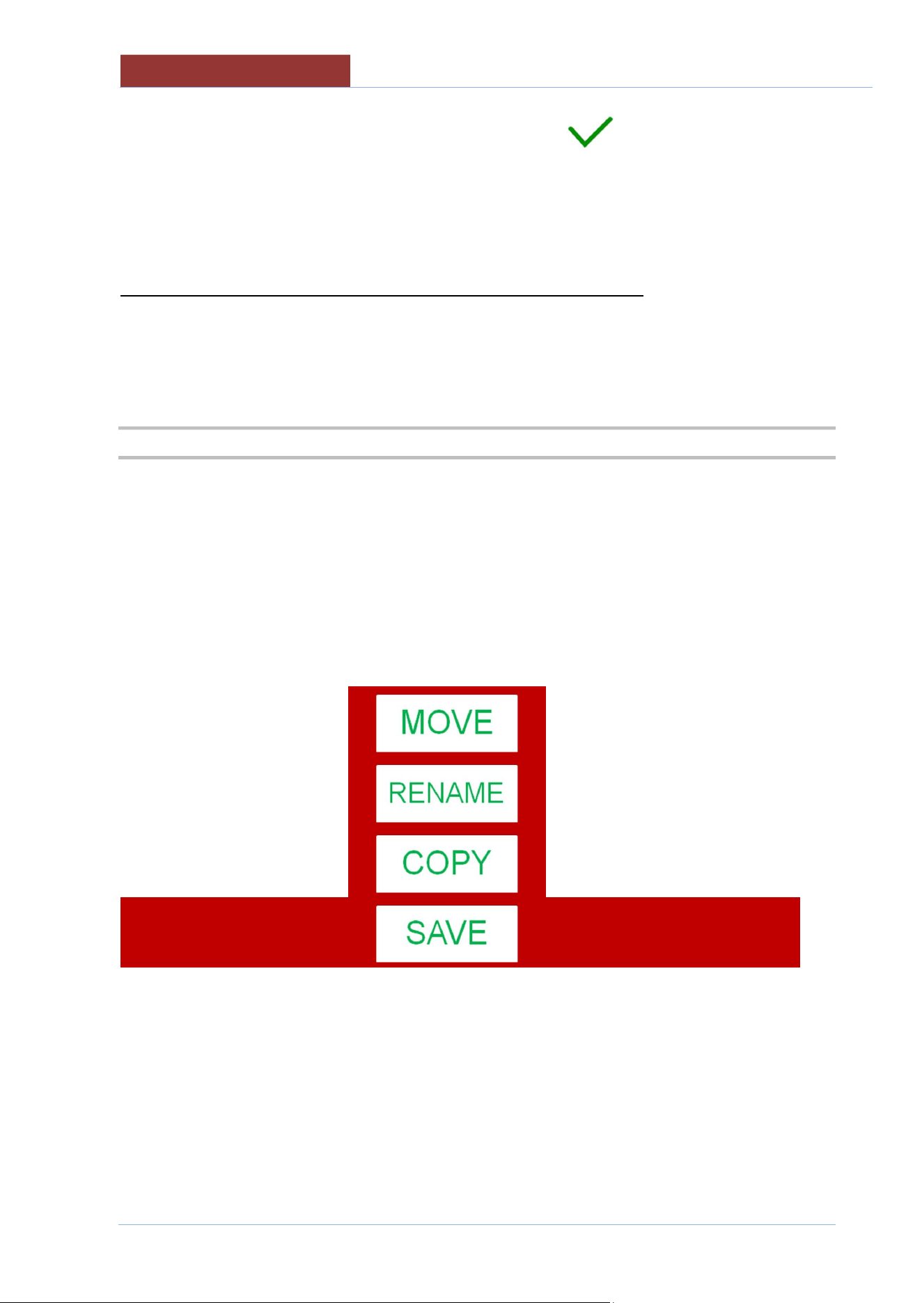
ENTER THE PROGRAM NAME AND CONFIRM WITH THE KEY .
ATTENTION : THE PROGRAM DOES NOT PERFORM A CHECK TO SEE IF A PROGRAM WITH THE
SAME NAME ALREADY EXISTS. 2 PROGRAMS WILL BE SAVED WITH THE SAME NAME, WITH HE
POSSIBILITY OF RENAMING THEM. (SEE EDITING PROGRAMS)
THE SCREEN APPEARS FOR LINKING THE PROGRAM TO A CATEGORY
18.4 EDIT/ COPY/ RENAME PROGRAM
FROM SETTINGS> PROGRAMS
SELECT THE CATEGORY OF THE PROGRAM OR ALL
SELECT THE PROGRAM THAT YOU WANT TO EDIT.
REFER TO "CREATING MULTIPHASE PROGRAMS" FOR EDITING
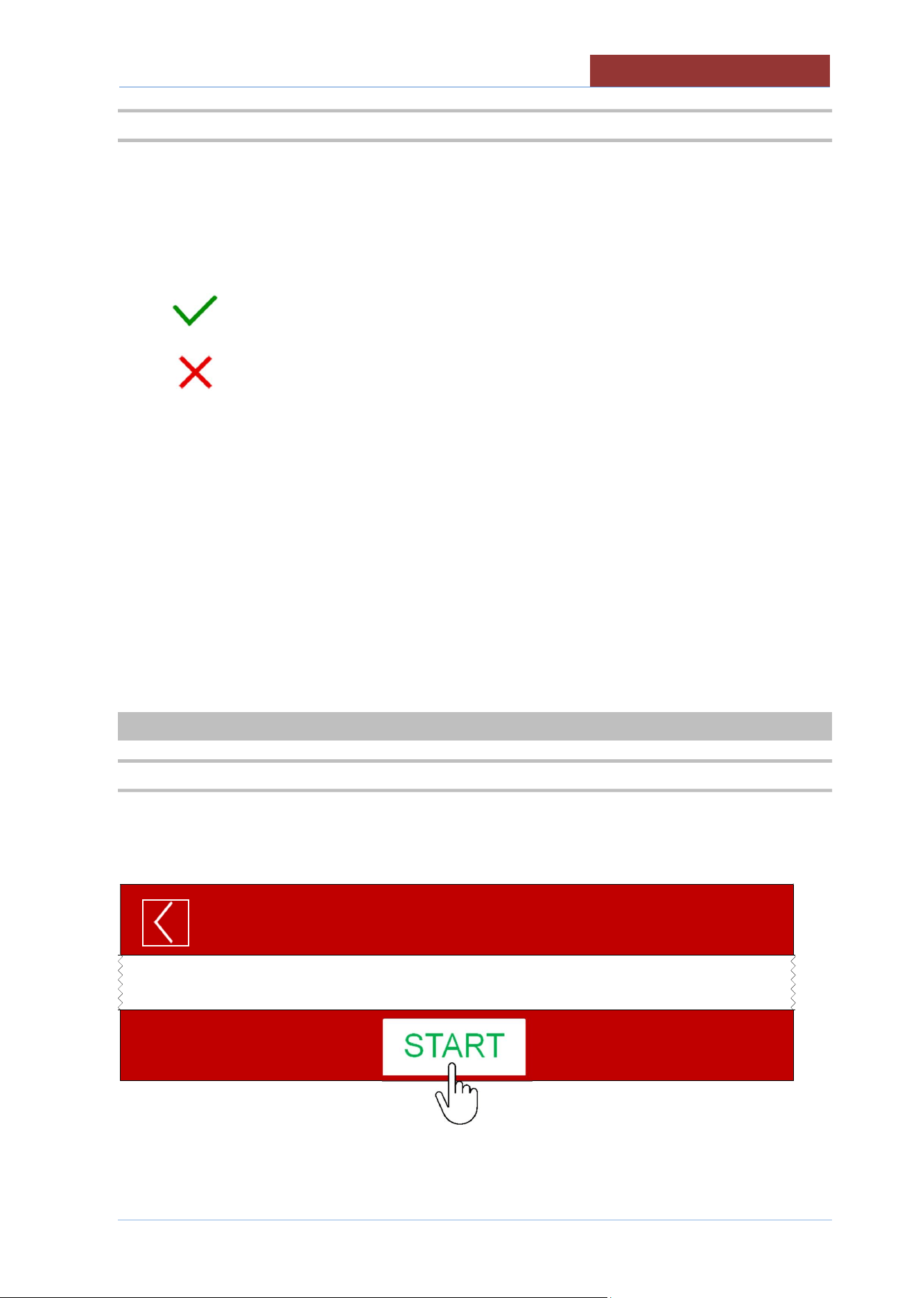
ONCE CHANGES HAVE BEEN MADE, PRESS THE SAVE KEY AND THE FOLLOWING SCREEN
APPEARS:
SAVE: SAVES THE PROGRAM (NO FURTHER REQUEST)
COPY: A NEW PROGRAM IS CREATED (GIVE THE NAME TO THE PROGRAM AND THE
CATEGORY)
RENAME: GIVES A NEW NAME TO THE PROGRAM (SAVING THE CHANGES MADE)
MOVE: MOVES THE PROGRAM TO ANOTHER GROUP (PRESS THE SAVE KEY TO CONFIRM)
RUNNING A PROGRAM/MANUAL COOKING
01
-
UDBRG_V1
-
DIMU
-
00
-
EN
59
18.5 DELETING A PROGRAM
FROM SETTINGS> PROGRAMS
SELECT THE CATEGORY OF THE PROGRAM OR ALL
SELECT THE PROGRAM YOU WANT TO DELETE BY PRESSING ON THE NAME OF THE
PROGRAM FOR ABOUT 2 SEC.
A POP-UP WILL BE APPEAR TO CONFIRM PROGRAM DELETION
CONFIRM DELETION
CANCEL DELETION
19 RUNNING A PROGRAM/MANUAL COOKING
19.1 RUNNING A PROGRAM/MANUAL COOKING
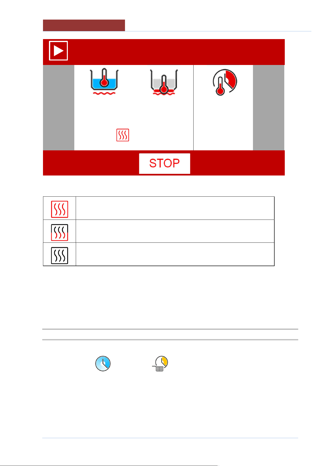
FROM PROGRAMS> MANUAL
SET ALL THE COOKING PARAMETERS
PRESS THE START KEY
MANUAL
01:27: 35
17/12/ 2016
THE SCREEN BECOMES
01
-
UDBRG_V1
-
DIMU
-
00
-
EN
RUNNING A PROGRAM/MANUAL COOKING
60
MANUAL
01:27: 35
17/12/ 2016
100°C
180°C
00:45:00
20°C
20°C
--:--:--
A SYMBOL APPEARS ON THE SIDE OF THE VALUE READ WITH THE FOLLOWING MEANINGS:
HEATING IN OPERATION
MINIMUM HEATING
HEATING OFF AS SETPOINT REACHED OR FOR WAITING (L COLUMN
ICONS)
WHEN RUNNING THE PROGRAM YOU CAN CHANGE THE TEMPERATURE AND TIME SETPOINT
BY PRESSING IN THE FIELD CORRESPONDING TO THE SET VALUES FOR ABOUT 2 sec. .
IT IS NOT POSSIBLE TO CHANGE THE COOKING METHOD AND TIME!!
19.2 END OF COOKING
EITHER WAIT UNTIL END OF COOKING TIME (IF TIME SET) OR PRESS THE STOP KEY.
IF THE SET TIME IS (INFINITE) OR (BASKETS), COOKING/HEATING CAN ONLY BE
ENDED BY PRESSING THE STOP KEY!
KEY!
RUNNING PROGRAMS (MULTI
-
PHASE)
01
-
UDBRG_V1
-
DIMU
-
00
-
EN
61
20 RUNNING PROGRAMS (MULTI-PHASE)
20.1 RUNNING PROGRAMS (MULTI-PHASE)
FROM PROGRAMS> SELECT THE PROGRAM THAT YOU WANT TO RUN FROM THE FOLDER: ALL;
CATEGORY (MEAT, SAUCES, ETC) OR FAVOURITES
PRESS THE START KEY
NOTE 1)
WHEN RUNNING THE PROGRAM YOU CAN CHANGE THE TEMPERATURE AND TIME SETPOINT
(ONLY IN THE PHASE IN WHICH THE PROGRAM IS CURRENTLY RUNNING) BY PRESSING IN THE
FIELD CORRESPONDING TO THE SET VALUES FOR ABOUT 2 sec. .
IT IS NOT POSSIBLE TO CHANGE THE COOKING METHOD AND TIME!!
NOTE 2)
YOU CAN MOVE ON TO THE NEXT PHASE (WITHOUT WAITING FOR THE PHASE IN PROGRESS
TO FINISH) BY PRESSING THE "PROGRAM PHASE" FIELD.
XXX1234
01:27: 35
17/12/ 2016
APPEARS:
x1
IT RETURNS TO THE PHASE IN PROGRESS
x2
IT PASSES TO THE NEXT PHASE.
ATTENTION: IF IT IS THE LAST PHASE, THE PROGRAM
FINISHES!
NOTE 3)
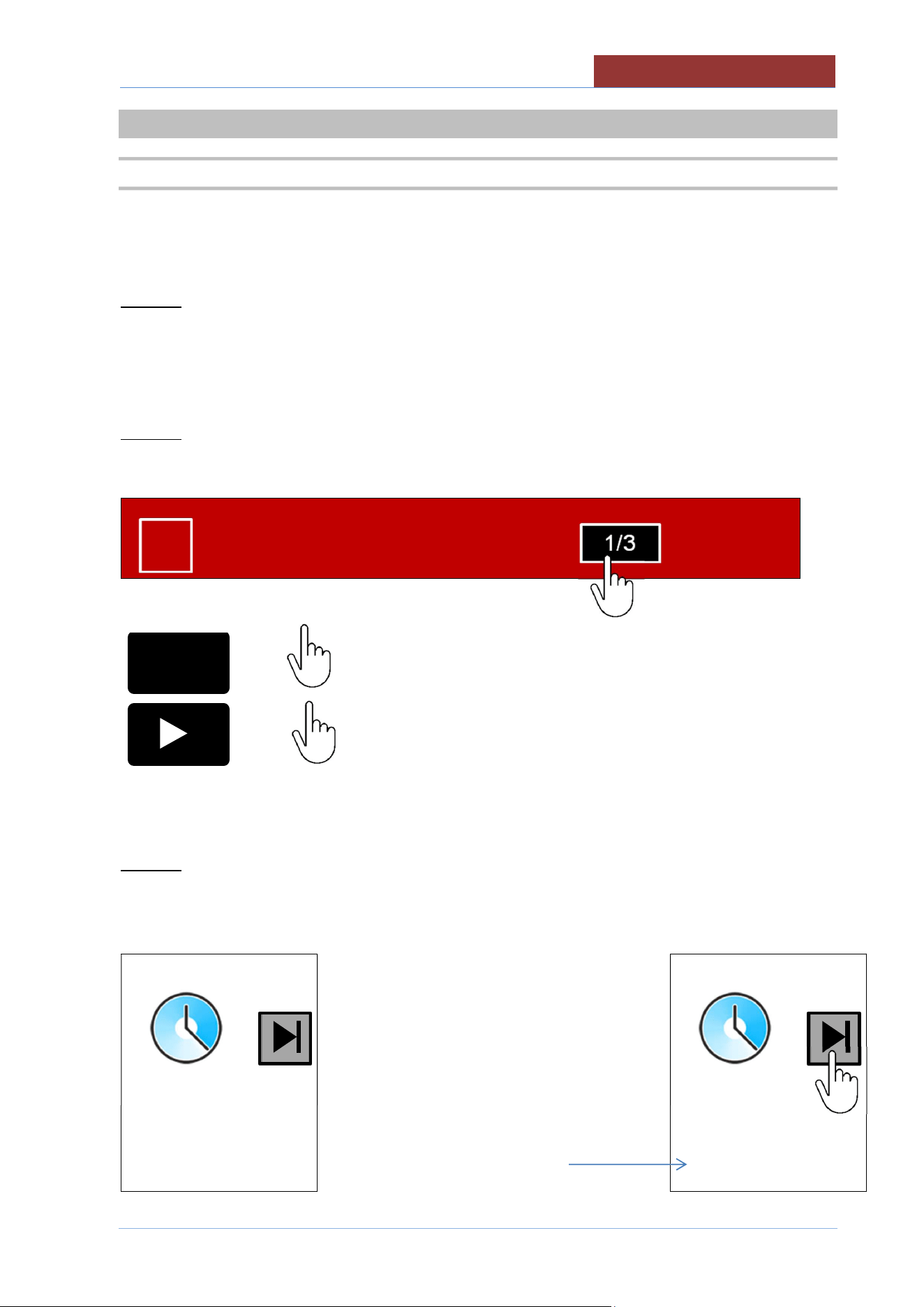
IF A PROGRAM HAS A PHASE SET WITH AN INFINITE TIME, THE MOVE TO THE NEXT STAGE IS
ACHIEVED BY PRESSING THE KEY TO THE SIDE OF THE TIME SYMBOL
Press the key to move on to the next phase
--:--:--
--:--:--
The time elapsed since
the beginning of the phase
is shown on the bottom row.
--:--:--
00:04:31
1/3
I
01
-
UDBRG_V1
-
DIMU
-
00
-
EN
RUNNING PROGRAMS (MULTI
-
PHASE)
62
NOTE 4)
IF YOU ARE RUNNING A PROGRAM WITH ACTIVE MESSAGES, WHEN THE MESSAGE APPEARS,
THE OPERATOR:
CAN PRESS THE BUZZER OR TURN OFF THE FLASHING (IF PRESENT IN THE MESSAGE)
MUST CONFIRM THE OPERATION REQUESTED TO CONTINUE WITH THE PHASE OR TO MOVE
ON TO THE NEXT PHASE.
NOTE 5)
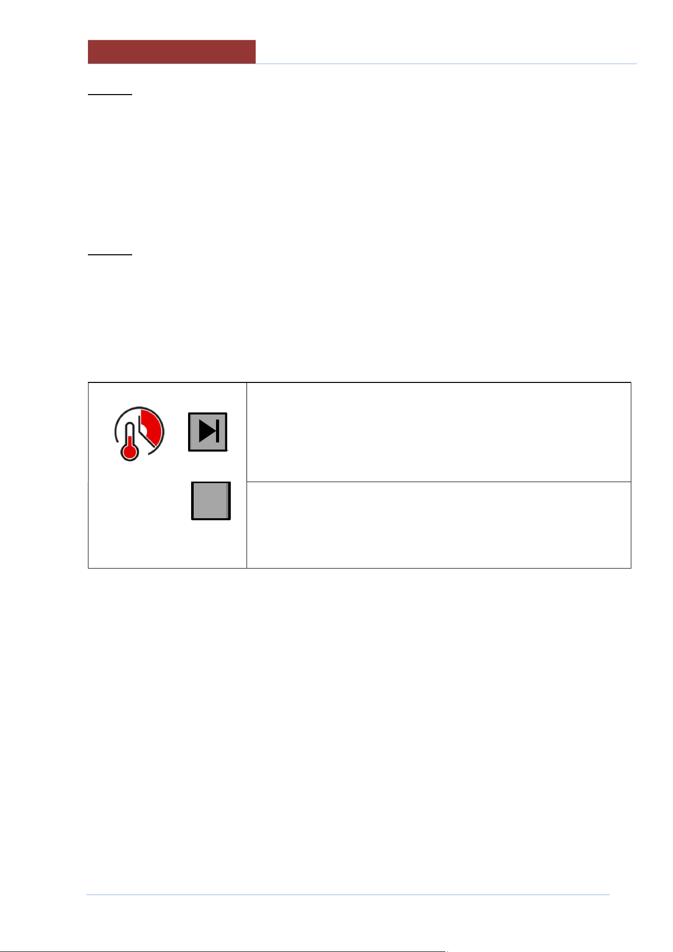
IF THE PROGRAM HAS THE ACTIVE MESSAGE "END" AT THE END OF THE COOKING TIME, THE
FOLLOWING MESSAGE APPEARS: END THE PHASE?
IF YOU PRESS "YES" , IT MOVES ON TO THE NEXT PHASE;
IF YOU PRESS "NO", THE FOLLOWING KEYS APPEAR:
key to move on to the next phase
00:45:00
00:00:11
key to increase the time (+ 1 minute each time the key is pressed)
The bottom row indicates the time passed since the cooking time elapsed.
AT THIS POINT IT IS NO LONGER POSSIBLE TO CHANGE THE TIME SETPOINT!
IN ORDER TO EXTEND THE COOKING:
EITHER YOU CHECK THE TIME PASSED ON THE LOWER ROW AND GO TO THE NEXT
STEP BY PRESSING THE KEY ABOVE;
OR PRESS THE +1 KEY (THE NUMBER OF TIMES CORRESPONDING TO THE DESIRED
NUMBER OF MINUTES). THE COUNTDOWN WILL BE DISPLAYED ON THE BOTTOM ROW
AND THE KEY ABOVE WILL DISAPPEAR. IT IS NOT POSSIBLE TO DECREASE THE
MINUTES SET. IF YOU MAKE A MISTAKE AND SET TOO MANY MINUTES, YOU HAVE TO
MOVE ON TO THE NEXT PHASE AS DESCRIBED IN NOTE 2.
ONCE THE TIME HAS RUN OUT, THE FOLLOWING MESSAGE WILL REAPPEAR: END THE PHASE?
+1
RUNNING
PROGRAMS (MULTI
-
PHASE)
01
-
UDBRG_V1
-
DIMU
-
00
-
EN
63
--:--:--
--:--:--
20.2 END OF PROGRAM
EITHER WAIT FOR THE END OF PROGRAM OR PRESS THE STOP KEY (+ CONFIRM).
IF THE SET TIME IS (INFINITE) OR (BASKETS), COOKING/HEATING CAN ONLY BE
ENDED BY PRESSING THE STOP KEY!
+1

01
-
UDBRG_V1
-
DIMU
-
00
-
EN
COOKING WITH DELAY TIMER
64
21 COOKING WITH DELAY TIMER
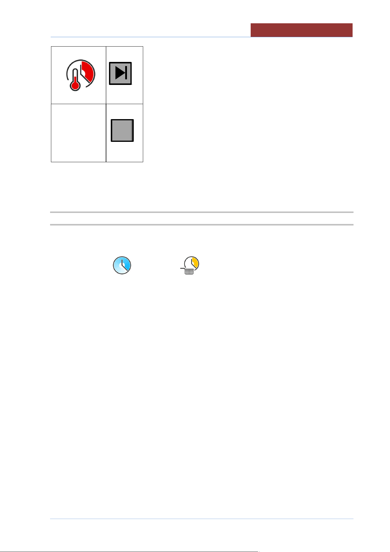
After having chosen the program to run,
press the button to access the settings for cooking with delay timer.
It is possible to set the delayed start in two ways:
Top row:
setting the start date and time: set the hour and minutes, and, if necessary, the day (with a maximum of 7
days in advance).
Bottom row:
setting delayed start: starting from the current time and date, set the hour and minutes, and if applicable
the day(s) delayed (with a maximum of 7 days in advance).
In automatic, when setting in one mode or the other, the other row will also be updated. (if the start time
and date are set, the delayed time will be updated, and vice versa).
To exit without saving, press the key .
Press the START key to confirm.
The display shows the time and date when it will start, and the bottom row shows the time remaining until
it starts.
To cancel the delayed start, press the STOP button.
Attention: check that there are no lights in the left column (e.g. pan out of position), otherwise
the cooking with delay timer will NOT be carried out.
FILLING PAN WITH H2O
01
-
UDBRG_V1
-
DIMU
-
00
-
EN
65
22 FILLING PAN WITH H2O
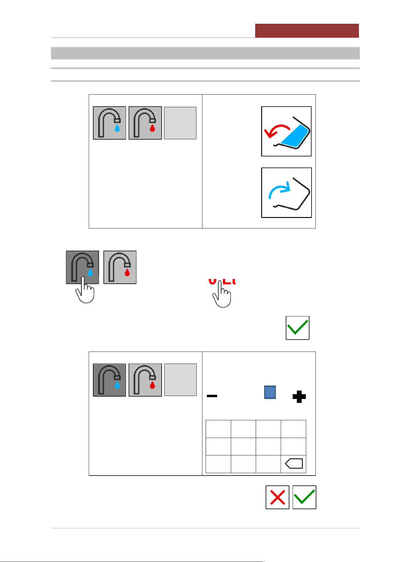
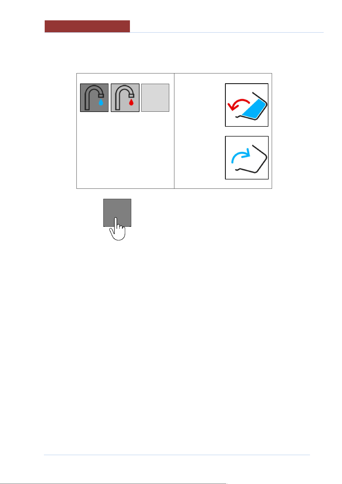
22.1 FILLING THE PAN WITH H2O USING A LITRE-COUNTER DEVICE
0 Lt
0 Lt
Select hot or cold water. Press on the Lt. Field
0 Lt
Set the number of litres you want to add and confirm with
120 Lt
min max
0 310
-----------------
1 2 3 4
5 6 7 8
- 9 0
START
x
START
01
-
UDBRG_V1
-
DIMU
-
00
-
EN
FILLING PAN WITH H2O
66
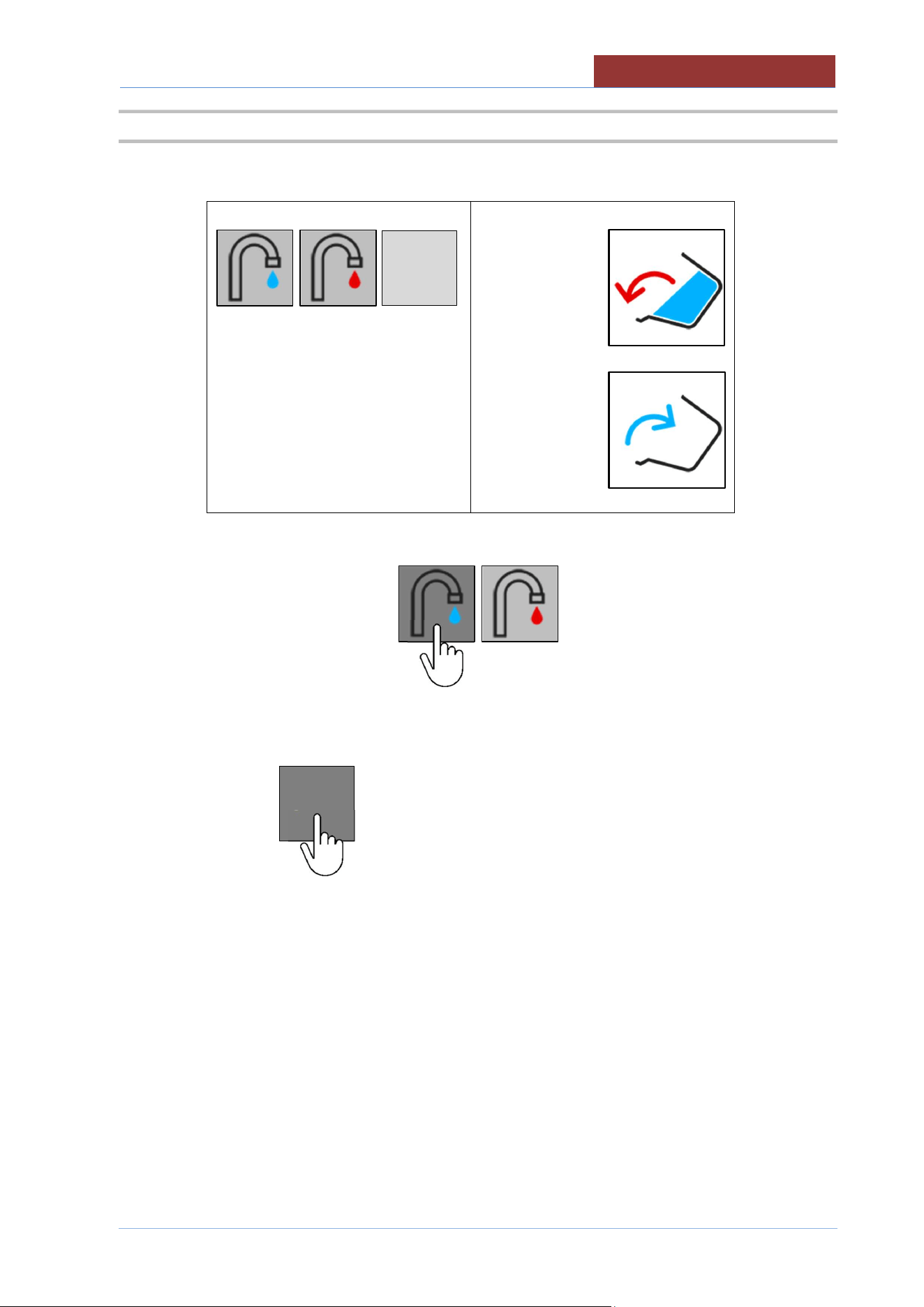
Press the "START" key
120 Lt
0 Lt
120 Lt litres set
10 Lt litres added
If you want to stop filling with water before the number of litres set is reached, press the "START"
key
START
START
FILLING PAN WITH H2O
01
-
UDBRG_V1
-
DIMU
-
00
-
EN
67
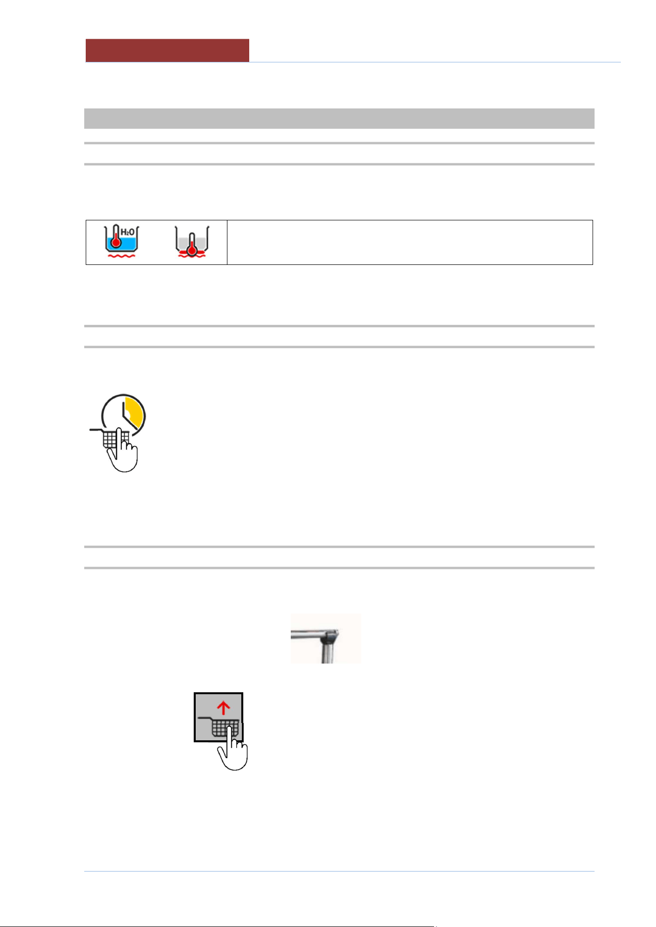
22.2 MANUALLY FILLING THE PAN WITH H2O
0 Lt
0 Lt
select hot or cold water
Keep the "START" key pressed down for the desired number of litres
0 Lt
10 Lt litres added
START
START
01
-
UDBRG_V1
-
DIMU
-
00
-
EN
COOKING WITH BASKETS (MOD.DBR .
.
-
C)
68
23 COOKING WITH BASKETS (MOD.DBR ..-C)
23.1 SELECTING THE COOKING METHOD
Select the required cooking method: "boiling"
Boiling
Set the desired temperature value
23.2 SELECTING COOKING TIME
Select the cooking time (baskets)
Set the desired time value
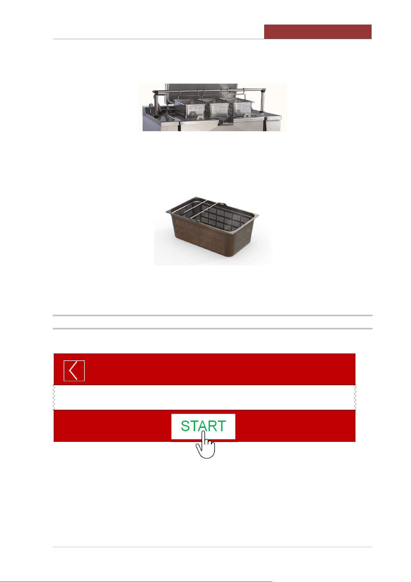
23.3 FITTING BARS AND BASKETS
Open the lid completely
Insert the bar into the side housings
Press the key
COOKING WITH BASKETS (MOD.DBR ..
-
C)
01
-
UDBRG_V1
-
DIMU
-
00
-
EN
69
Wait until the bar is completely lifted and hook the baskets, previously loaded with the product to be cooked,
to the bar.
ATTENTION:
Use baskets appropriate for the cooking method.
Baskets for boiling
23.4 STARTING HEATING
PRESS THE START KEY
MANUAL
01:27: 35
17/12/ 2016
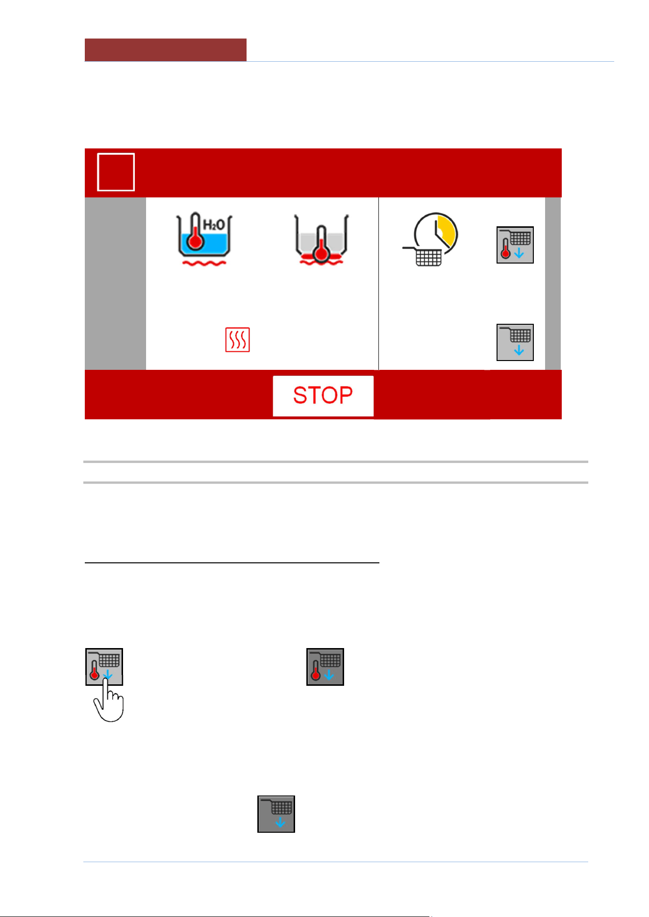
01
-
UDBRG_V1
-
DIMU
-
00
-
EN
COOKING WITH BASKETS (MOD.DBR ..
-
C)
70
THE SCREEN BECOMES
MANUAL
01:27: 35
17/12/ 2016
100°C
180°C
00:00:06
20°C
20°C
--:--:--
23.5 IMMERSING THE BASKETS
The baskets can be immersed in the cooking pan in the following 2 ways:
Baskets immersed upon reaching the SETPOINT temperature
This is recommended when the cooking liquid (water or oil) is not yet at the required temperature, or
when a precise temperature of the cooking liquid is required, before immersing the basket.
When the following key
becomes dark grey when pressed = lowering enabled at SETPOINT temperature.
When the key is pressed again it turns light grey and the function is disabled!
When the SETPOINT temperature is reached, a message appears with a countdown for basket lowering,
at the end of which the key appears (in dark grey) until the baskets are automatically lowered to
the cooking position.
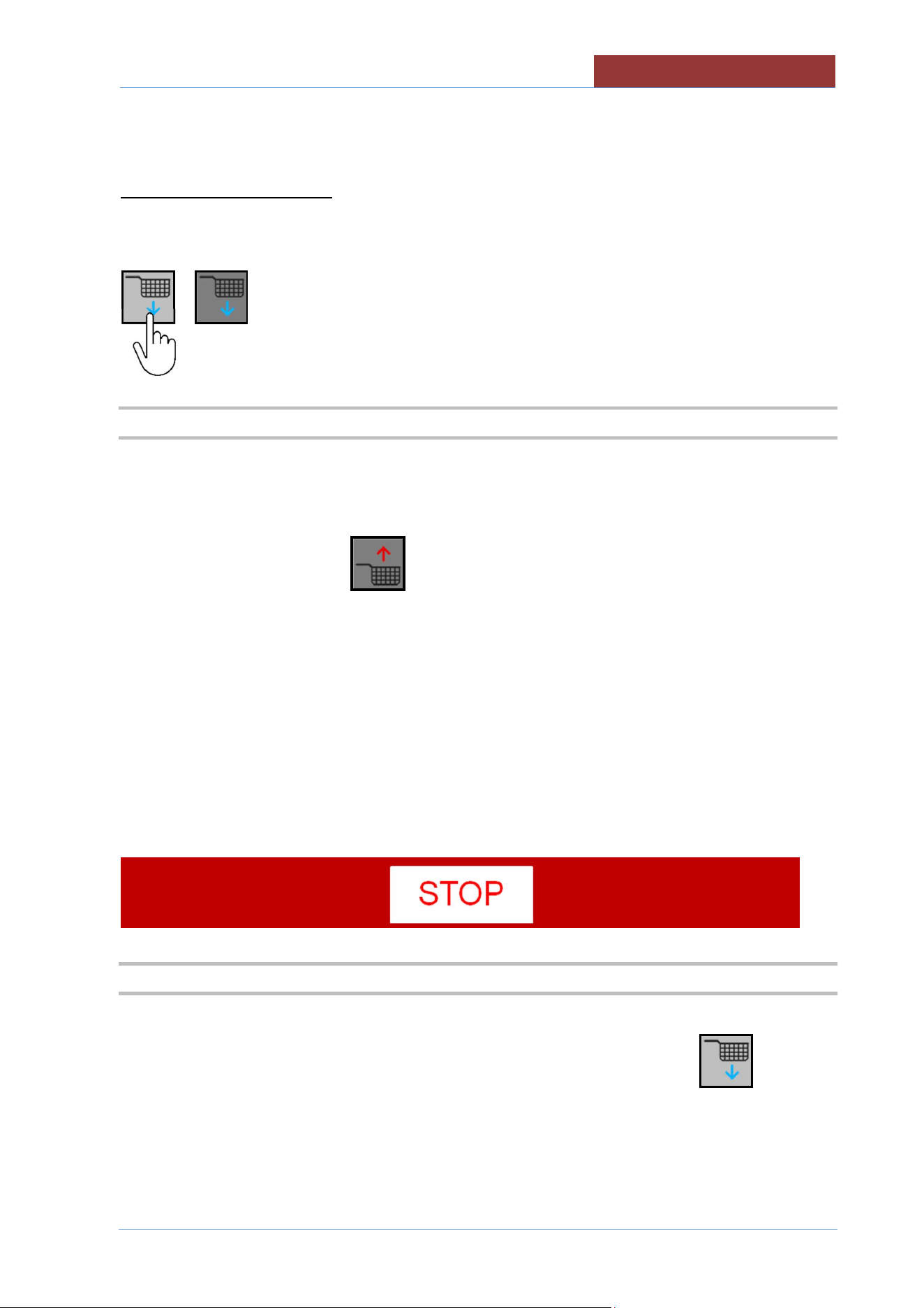
COOKING WITH BASKETS (MOD.DBR ..
-
C)
01
-
UDBRG_V1
-
DIMU
-
00
-
EN
71
Baskets immersed immediately
When the following key
turns grey and the baskets are lowered immediately to the cooking position.
23.6 COOKING TIME (BASKET IMMERSION)
Once the baskets have reached the cooking position, the countdown of the set cooking time starts.
Before the cooking time runs out (about 10 sec.), a message appears with the countdown for basket
lifting, at the end of which the key appears (in dark grey) until the baskets are automatically lifted
to the loading/unloading position.
At this point it is possible to empty the cooked product.
If you want to run a new cycle, load the new product and repeat the cooking cycle as described above.
ATTENTION:
The countdown of the cooking time will NOT start if the heating has not been started!!
The key on the function bar must be "STOP".
23.7 END OF COOKING/HEATING
At the end of the cooking cycles, switch off the heating by pressing the STOP button.
Remove the baskets from the bar and the bar from the supports and press the button to bring the
lifting system back into the rest position.
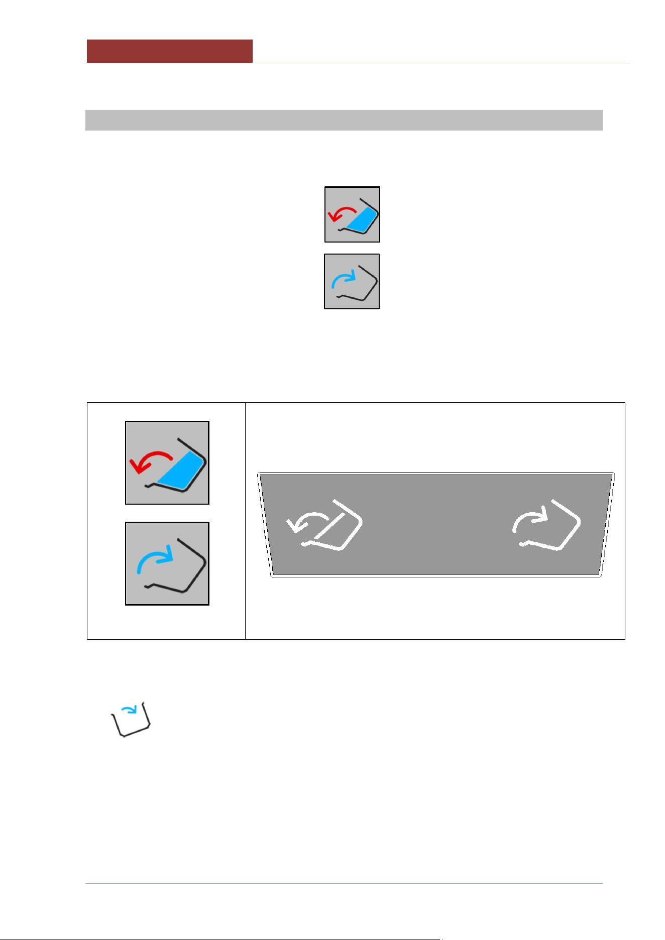
01
-
UDBRG_V1
-
DIMU
-
00
-
EN
MOVING THE PAN
72
24 MOVING THE PAN
To move the cooking vessel, keep pressed the corresponding key on the display or external keypad.
The keys on the display are disabled when the pan tilting limits are reached.
With a completely horizontal pan = enabled only
With a tilted pan = enabled only
DISPLAY KEYPAD
Pan tilting key
Pan return key
Pan tilting key Pan return key
As tilting prevents the heating and mixing functions, whenever the pan is not in a horizontal position, the
icon appears.
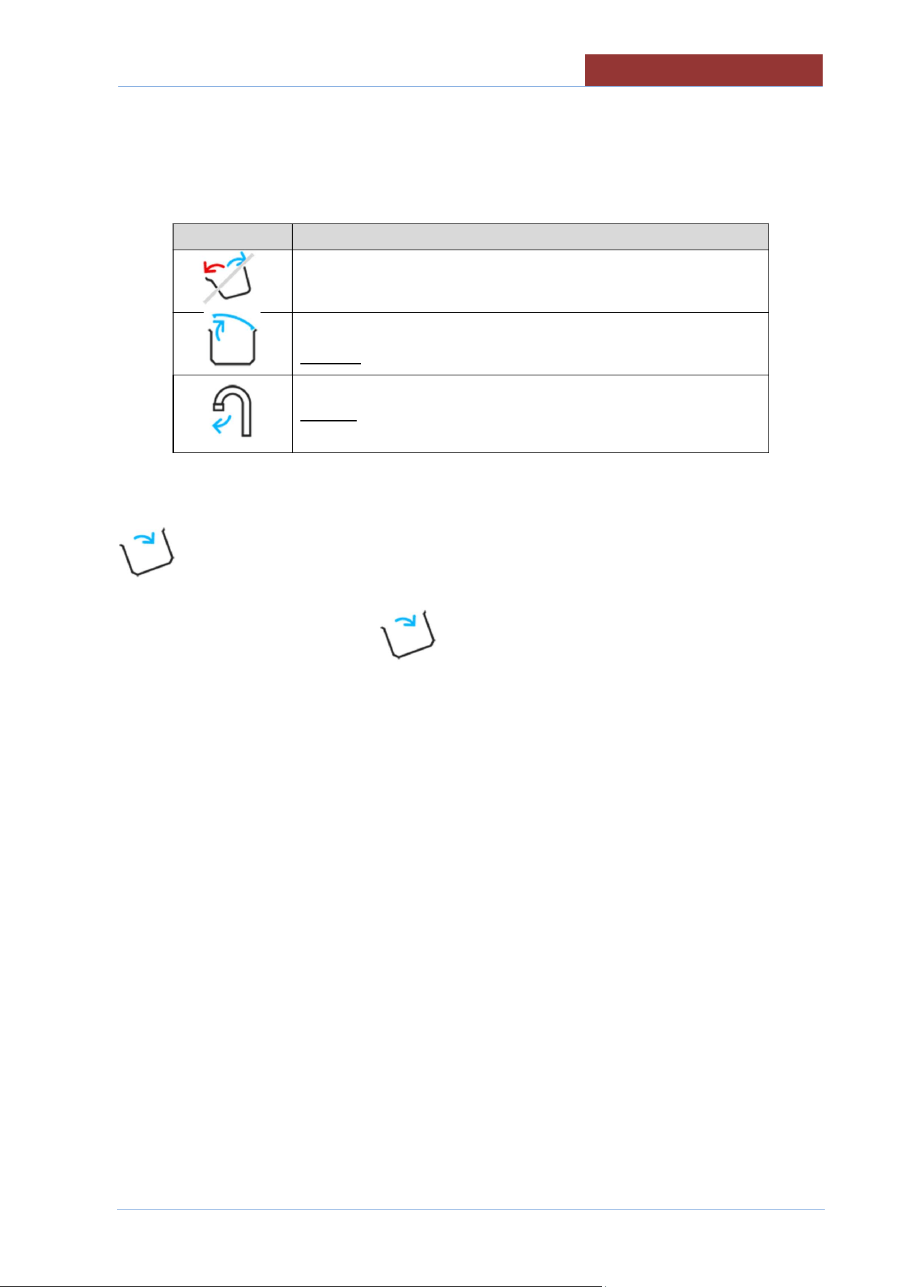
MOVING THE PAN
01
-
UDBRG_V1
-
DIMU
-
00
-
EN
73
Any messages that prevent pan movement appear in the left column.
Icon Description
Pan movement not allowed
Request to completely open the lid (for pan movement)
Request to turn the tap (for pan movement)
To return the pan to the horizontal position, press and hold the corresponding key, until the icon
disappears.
ATTENTION: The presence of the icon prevents the cooking functions of the machine.
01
-
UDBRG_V1
-
DIMU
-
00
-
EN
CLEANING AND CARE
74
25 CLEANING AND CARE
25.1 GENERAL INFORMATION
Do not use aggressive substances or abrasive detergents when cleaning stainless steel
parts.
Avoid using iron scourers on steel parts as rust formation may occur. For the same
reason avoid contact with ferrous materials.
No sandpaper or abrasive paper should be used during cleaning. In special cases,
pumice stone may be used in powder form.
In the event of particularly resistant dirt, we recommend the use of abrasive sponges
(e.g. Scotch-Brite).
25.2 DAILY CLEANING
Always wear protective clothing required by current regulations.
For safety reasons, clean the machine when it is cold and off (with the emergency button
pressed) (or on stand-by if cooking with delay timer).
When cleaning the appliance never spray water directly in order not to cause
infiltration and damage to the parts.
Never use water jets in the flue in gas versions.
Clean the pan with water and detergent, rinse well and dry thoroughly with a soft cloth
Clean the outside with a sponge soaked in hot water and a suitable detergent readily available on the
market.
Always rinse well and dry with a soft cloth.
Be careful not to damage the lid seal.
Clean the seal with NON-abrasive liquid detergent.
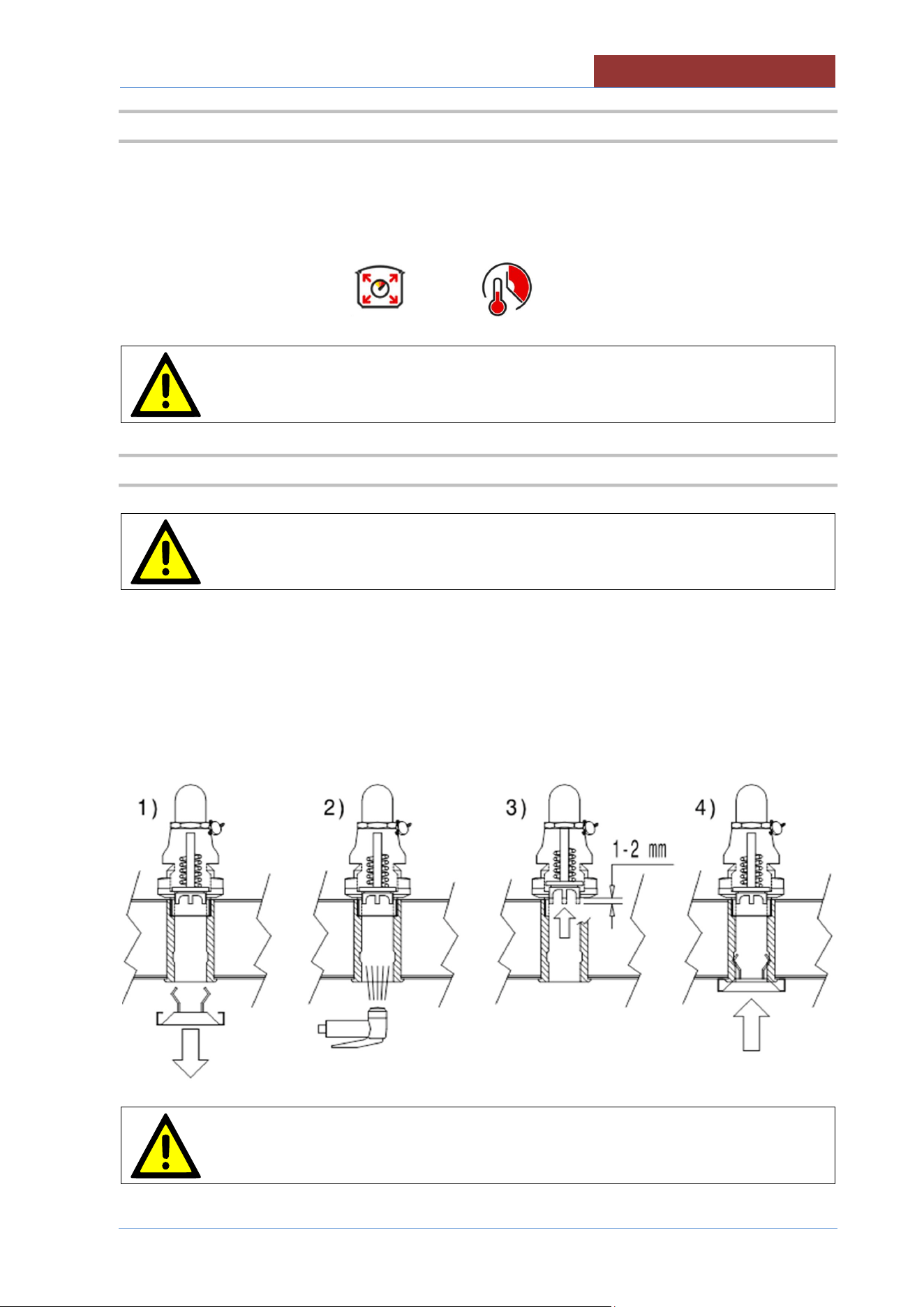
CLEANING AND CARE
01
-
UDBRG_V1
-
DIMU
-
00
-
EN
75
25.3 CLEANING THE PRESSURE COOKER SYSTEM
Clean the pressure system as described below:
1) Pour in water equal to about 10% of the pan's capacity (e.g. mod.180 = 18 litres), or about 1 “
(2/3 cm) of water in the bottom of the pan.
2) Start a 5-minute pressure cooking cycle
The cleaning cycle must be performed weekly.
Depending on how often pressure cooking is used and/or the product used, the
cleaning cycle may also be performed more frequently.
25.4 CLEANING AND CHECKING THE SAFETY VALVE
Thoroughly clean the safety valve housing from inside the lid as described below
1) Remove the spring loaded lid.
2) Remove the residue that may stick the poppet to the valve housing
3) At the end of cleaning, check that the valve poppet is free.
4) Refit the spring loaded lid
The check described in point 3 must be carried out at least once a month
01
-
UDBRG_V1
-
DIMU
-
00
-
EN
CLEANING AND CARE
76
25.5 PRECAUTIONS IN CASE OF PROLONGED INACTIVITY
If the appliance has been inactive for a prolonged period of time (holidays, seasonal work...), clean well,
remove any residue and ensure it is dry.
Leave the lid open so that air can circulate inside the pan.
The room must be sufficiently ventilated.
Disconnect all water, electricity and gas supplies.
25.6 PRECAUTIONS IN CASE OF MALFUNCTION
Should malfunctions occur during use, switch off the appliance immediately and disconnect or stop all
supplies (gas and water).
Request assistance from technical support or a qualified technician.
The manufacturer assumes no responsibility or warranty commitment for injuries
and damage due to non-compliance with the instructions or any installation or
maintenance that does not comply with safety standards.
The same applies in case of improper use of the appliance by the operator.

MAINTENANCE
01
-
UDBRG_V1
-
DIMU
-
00
-
EN
77
26 MAINTENANCE
26.1 MAINTENANCE OF THE APPLIANCE
All maintenance work must only be performed by a specialist technical service
centre!
In order to keep the appliance working efficiently, it is advisable to perform annual
maintenance, which includes checking the status of components subject to wear and
tear (pipes, etc.).
It is advisable to replace any worn components during maintenance, in order to avoid
further call outs and unexpected issues and faults with the appliance.
Therefore, it is recommended to sign a maintenance contract with a reliable technical
support centre.
26.2 PERIODIC MAINTENANCE
Periodic inspections will minimise machine downtime and increase operating efficiency.
The following points must be checked:
Periodic inspections will minimise machine downtime and increase operating efficiency.
The following points must be checked:
BY OPERATOR
DAILY CHECKS
1. Thoroughly clean the machine daily
QUARTERLY CHECKS
2. Check the following are undamaged and intact:
Screen controls, switches, warning lights.
Emergency button:
Contact technical support if they are damaged.

01
-
UDBRG_V1
-
DIMU
-
00
-
EN
MAINTENANCE
78
BY SERVICE TECHNICIAN
For each operation:
Carefully close all the panels. .
The inside of the appliance should be kept clean.
Electrical wiring should be kept securely connected and in good condition.
ANNUAL CHECKS / ACTION
1. Check coupling panels, must be perfectly closed with all the screws.
2. Check the sealing water system (load tap water).
3. Check that terminals connections of electrical parts are well fastened. Clean electrical parts .
Contact technical support if they are damaged.
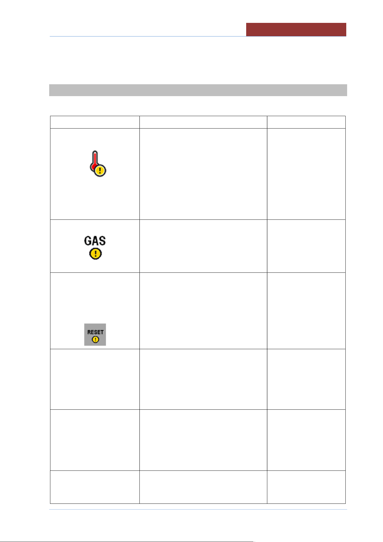
DISPLAY MESSAGES
01
-
UDBRG_V1
-
DIMU
-
00
-
EN
79
27 DISPLAY MESSAGES
Message Meaning Solution
Safety thermostat has been triggered
The safety thermostat can be disarmed
during transport without any issues.
Reset the thermostat
from the lower panel on
the right hand side, by
pressing firmly on the red
thermostat key.
If the thermostat is
triggered again, contact
the support centre.
Insufficient gas pressure.
It is not possible to start cooking.
Verify that gas is
supplied and that the
pressure is sufficient.
Contact the support
centre.
!! BLOCK GAS
DEVICE !!
PRESS
**RESET**
If a cooking phase has started and
insufficient gas pressure has been
detected on 4 consecutive occasions or
there is a fault on the flame detection
system, the central unit will be interrupted.
Press “RESET”.
After 3 RESET attempts,
the message below
appears.
!! GAS SYSTEM
ANOMALY!!
CONTACT TECHNICAL
ASSISTANCE
Problem with the gas system: gas central
unit fuses, gas solenoid valve, spark plugs
and pilot light plug.
Contact technical support.
PROBES ERROR
One or more of the
appliance's
sensors/probes are faulty (or not
connected). Cooking methods that use
these sensors/probes will be disabled (light
grey) until they are repaired.
Contact technical support.
INTERNAL ERROR
Connection error between the relay board
and keypad board
Switch the appliance off,
and switch back on after
two minutes, if the

01
-
UDBRG_V1
-
DIMU
-
00
-
EN
DISPLAY MESSAGES
80
System board error.
problem persists, call a
technician
BLACK OUT ERROR
t.b.d
INVERTER ERROR
Connection error between relay board and
inverter
Contact
technical support.
EXTERNAL MEMORY
ERROR
SD memory card not available.
Contact technical support.
OUTPUT
CONFIGURATION
ERROR
PROGRAMMING ERROR. Dual output
assignment!!
Contact technical support.