Name
11368793、11368802
NO.
Date
2025-11-06
Ver
A0
page
1/14
BIGTIDE
VER:A0
SPECIFICATON
Remote control wireless receiver/11368802
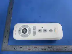
Wireless remote control/11368793
Name
11368793、11368802
NO.
Date
2025-11-06
Ver
A0
page
2/14
CONTENTS
1 SCOPE 3
1.1 REFERENCES 3
1.2 RC COMPONENTS: 3
2 ELECTRICAL SPECIFICATIONS 4
2.1 POWER ELECTRICAL CHARACTERISTICS 4
2.2 REMOTE CONTROL WIRELESS RECEIVER/ INTERFACE PINOUT 4
2.3 BLE CHARACTERISTICS 4
2.4 WIRELESS RMC ELECTRICAL FUNCTIONS 5
2.5 TRANSCEIVER CAN ISOLATION 5
2.6 DMG ISOLATION 5
3 PANEL FUNCTION SPECIFICATIONS 6
3.1 PANEL OPERATING ELEMENTS 6
3.2 KEY AND INDICATOR LIST 6
3.3 DOME 7
3.4 LED 7
3.5 MEMBRANE 8
3.6 DEADMAN 8
3.6.1 CAP SENSOR 8
3.6.2 DOUBLE KEY 9
3.7 BLE PAIRING 10
3.8 BATTERY AND CHARGING 10
3.9 POWER SAVE 11
4 MACHICAL SPECIFICATIONS 12
4.1 OUTLINE DIMENSIONS 12
4.2 PACKAGING 13
5 REGULATIONS AND STANDARDS 14
5.1 OPERATION ENVIRONMENT 14
5.2 KEY RELIABILITY 14
5.3 TRANSPORT CONDITIONS 14
Name
11368793、11368802
NO.
Date
2025-11-06
Ver
A0
page
3/14
1 Scope
This document establishes the detail specification of the CT Remote Control for SSME in terms
of electrical, mechanical, environmental characteristics. Also included are the brief
specifications of the major components and their configuration methods.
1.1 References
EPH WRCC functional specification251106
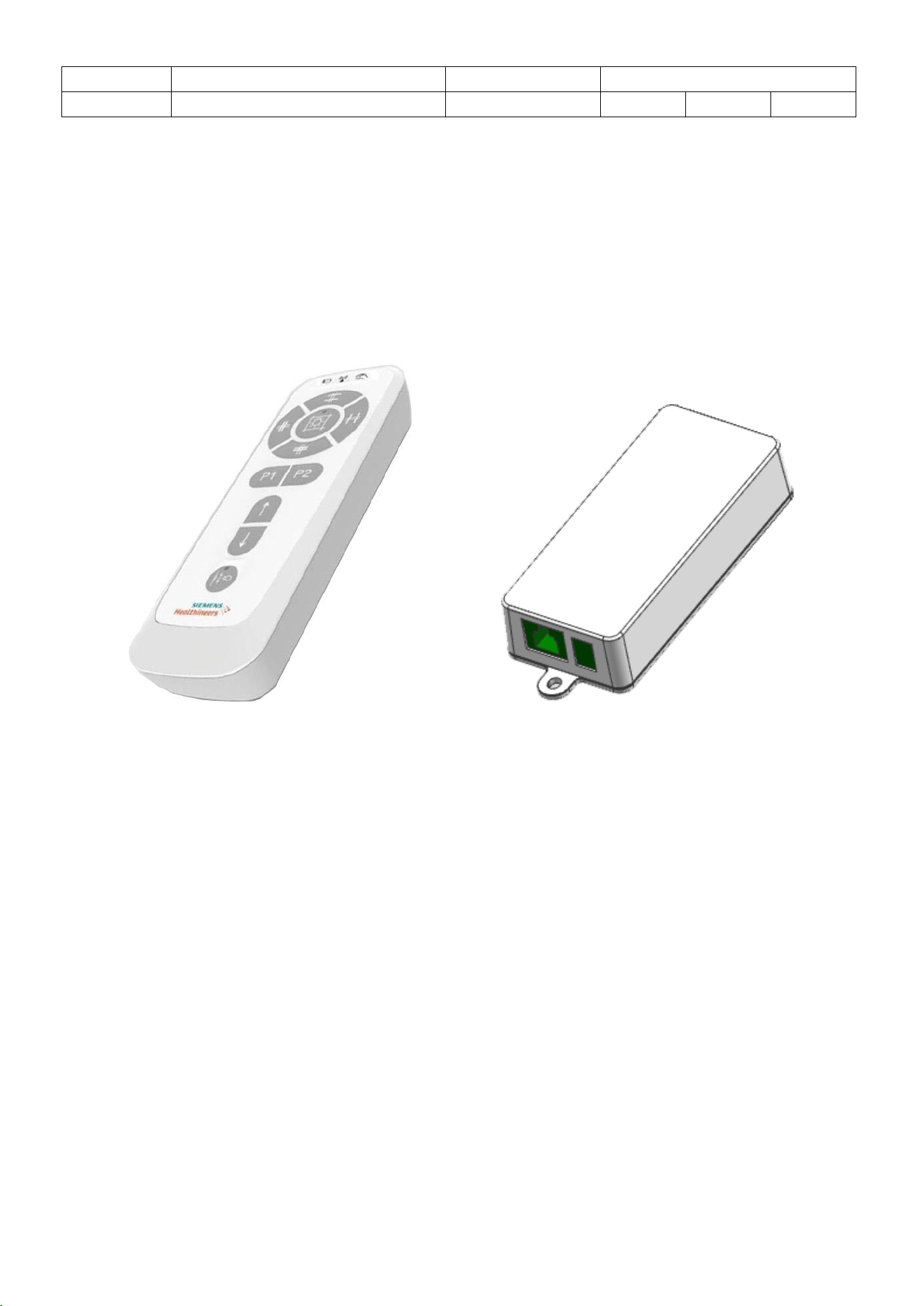
1.2 RC components:
Wireless remote control/11368793 Remote control wireless receiver/11368802
Name
11368793、11368802
NO.
Date
2025-11-06
Ver
A0
page
4/14
2 Electrical Specifications
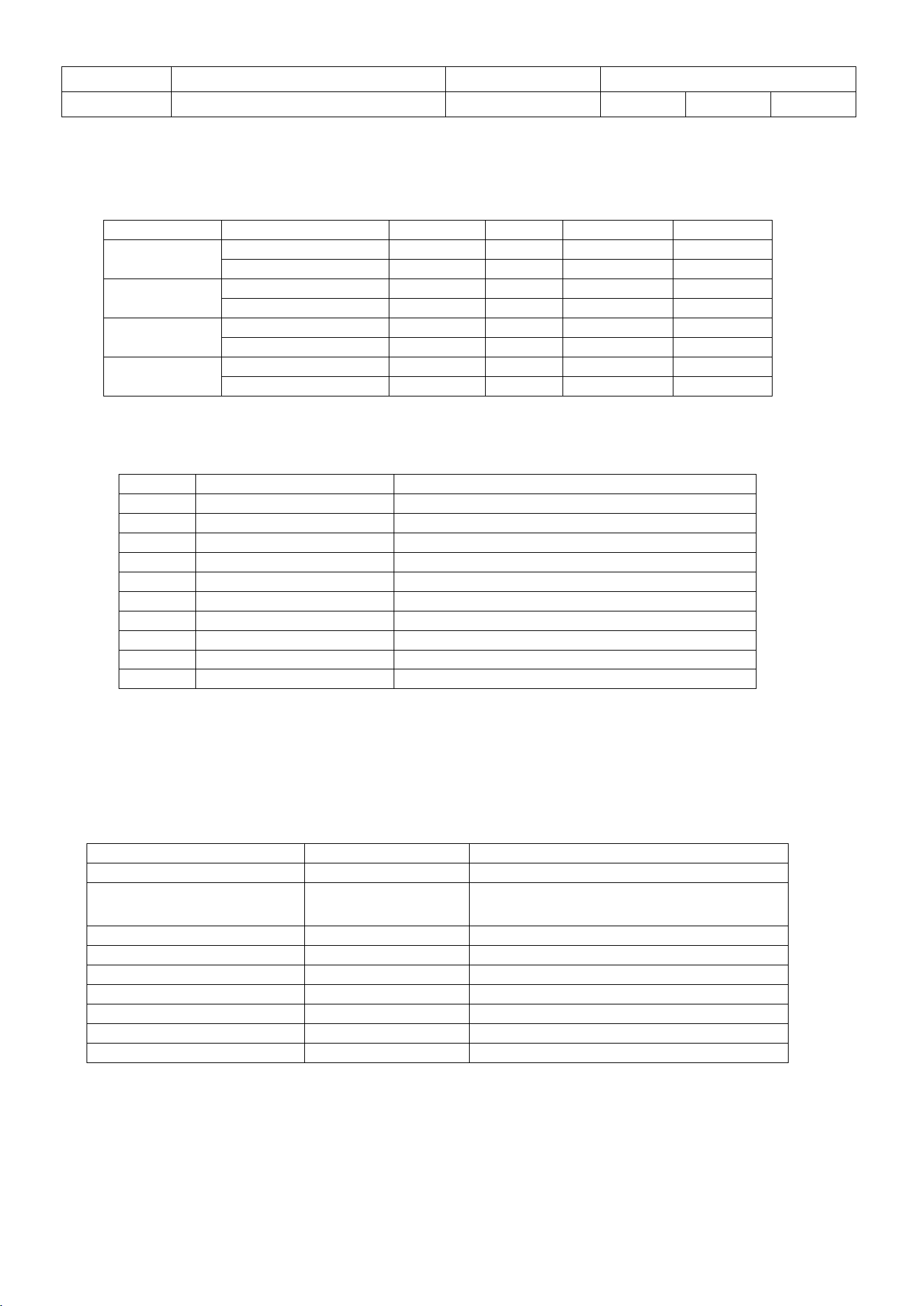
2.1 Power Electrical characteristics
2.2 Remote control wireless receiver/ interface pinout
2.3 BLE Characteristics
Unit
Min
Type
Max
Battery
Voltage
Vdc
1.2V
1.35V
battery capacity
mAh
1800mAh
Handset
Supply Voltage
Vdc
2.0V
1.2V*2
2.8V
Current
mA
7mA
30mA
70mA
Charger
Input Voltage
Vdc
4.75V
5V
5.25V
Charger Current
mA
10mA
270mA
300mA
Receiver
terminal
Supply Voltage
Vdc
21.6V
24V
26.4V
Current
mA
20mA
35mA
80mA
Pin#
Defines
Descriptions
1
CAN_H
CAN bus to wireless receiver board
2
CAN_L
CAN bus to wireless receiver board
3
GND
CAN bus ground
4
NC
5
NC
6
NC
7
GND
Ground for 24V
8
24V
Power supply
Shield
Protective Earth
ITEM
Parameter
Remarks
Center frequency
2.36-2.5MHz
Programmable
Modulation
GFSK
2/1Mbps,Long range:125/500kbps,
802.15.4-2006:250kbps
Output power
-20 - +8dBm
Receiving sensitivity
-103dBm
125kbps(long range)
Receiving current
4.8mA
@1Mbps
Transmitting current
14mA
TX Power 8dBm
Transmitting current
4.9mA
TX Power 0dBm
MCU
Nordic nRF52833
Cortex M4F
Antenna
PCB Type F or IPX
Name
11368793、11368802
NO.
Date
2025-11-06
Ver
A0
page
5/14
2.4 Wireless RMC electrical functions
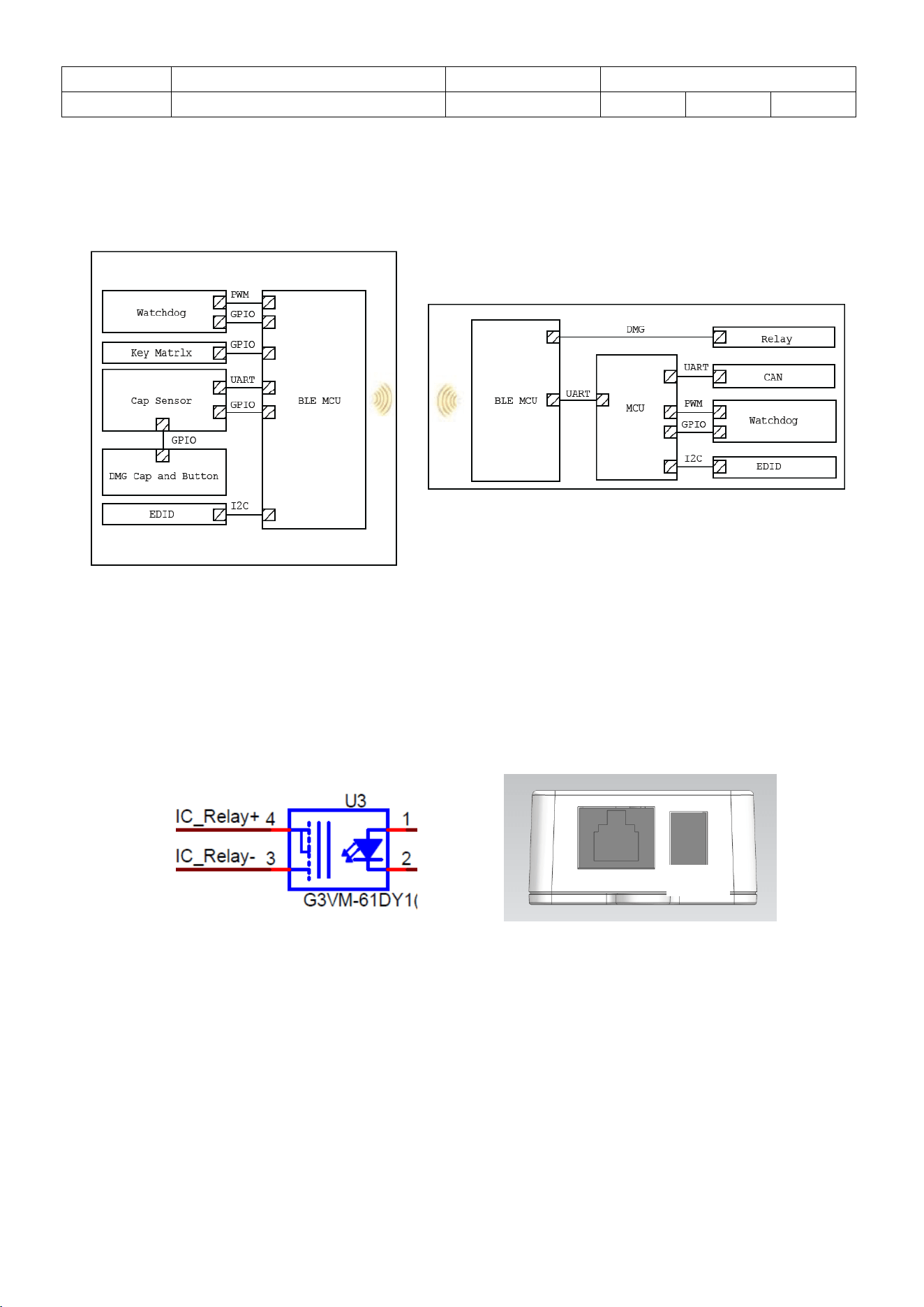
The wireless RMC transmit the signal to system control board by receiver that installed in the
gantry.
Operating area of wireless remote control shall be at least 7m.
2.5 Transceiver CAN Isolation
The CAN interface of the transceiver shall provide an isolation of 1.5KV AC.
2.6 DMG Isolation
K1 relay is DMG output on X5,
X5
Name
11368793、11368802
NO.
Date
2025-11-06
Ver
A0
page
6/14
3 Panel Function Specifications
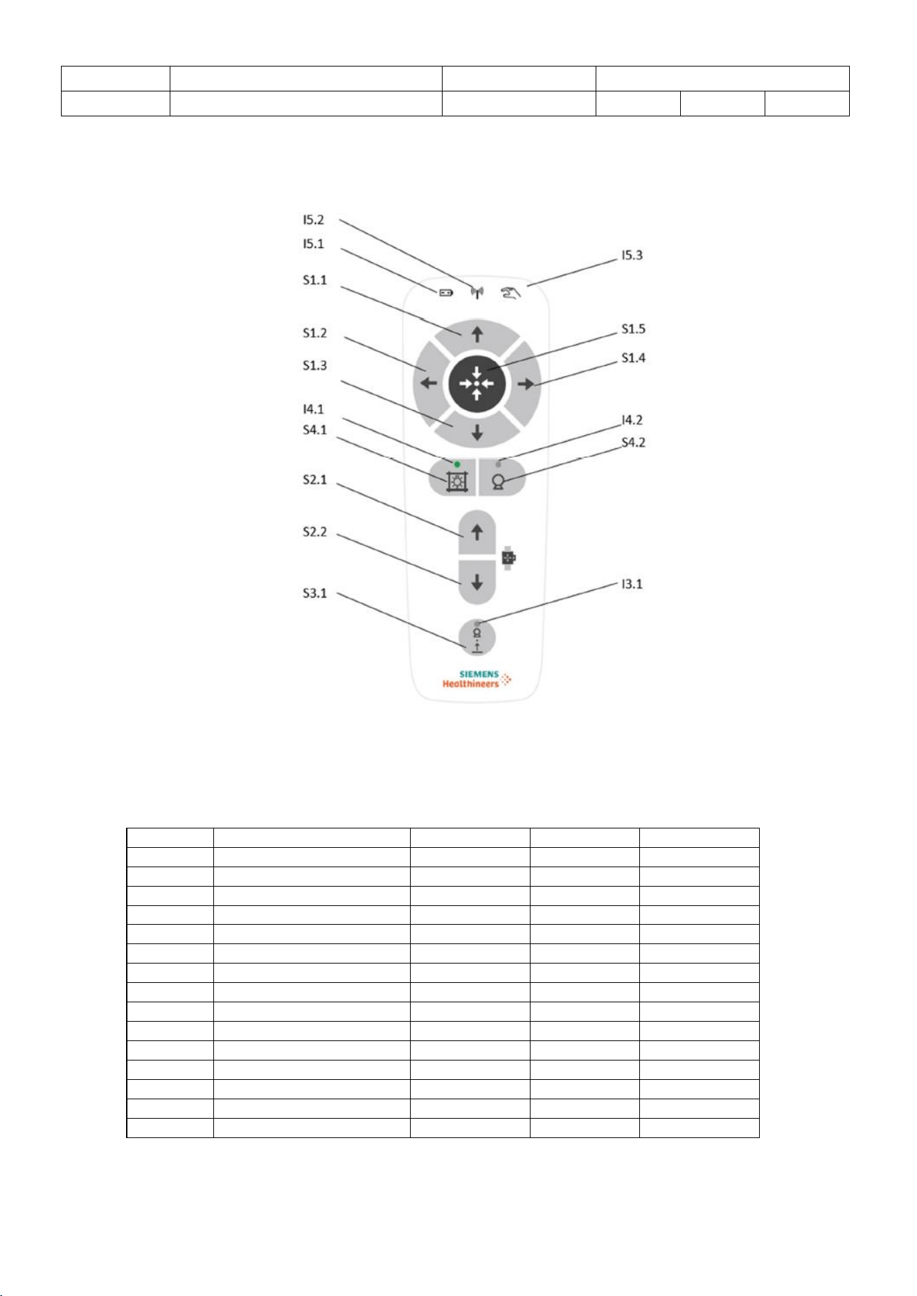
3.1 Panel Operating Elements
3.2 Key and Indicator list
H/R
Function
LED Color
K/L
Description
I5.1
Battery power indicator
Red/Yellow
LED
I5.2
BLE Signal indicator
Yellow
LED
I5.3
Button pressed indicator
Yellow
LED
S1.1
Open vertical
KEY
S1.2
Close horizontal
KEY
S1.3
Close vertical
KEY
S1.4
Light localizer ON/OFF
KEY
I1.4
Light ON/OFF
Green
KEY&LED
S1.5
Open horizontal
KEY
S2.1
BWS up
KEY
S2.2
BWS down
KEY
S3.1
Tracking
KEY
I3.2
Tracking indicator
White
KEY&LED
S4.1
Position1#
KEY
S4.2
Position2#
KEY
Name
11368793、11368802
NO.
Date
2025-11-06
Ver
A0
page
7/14
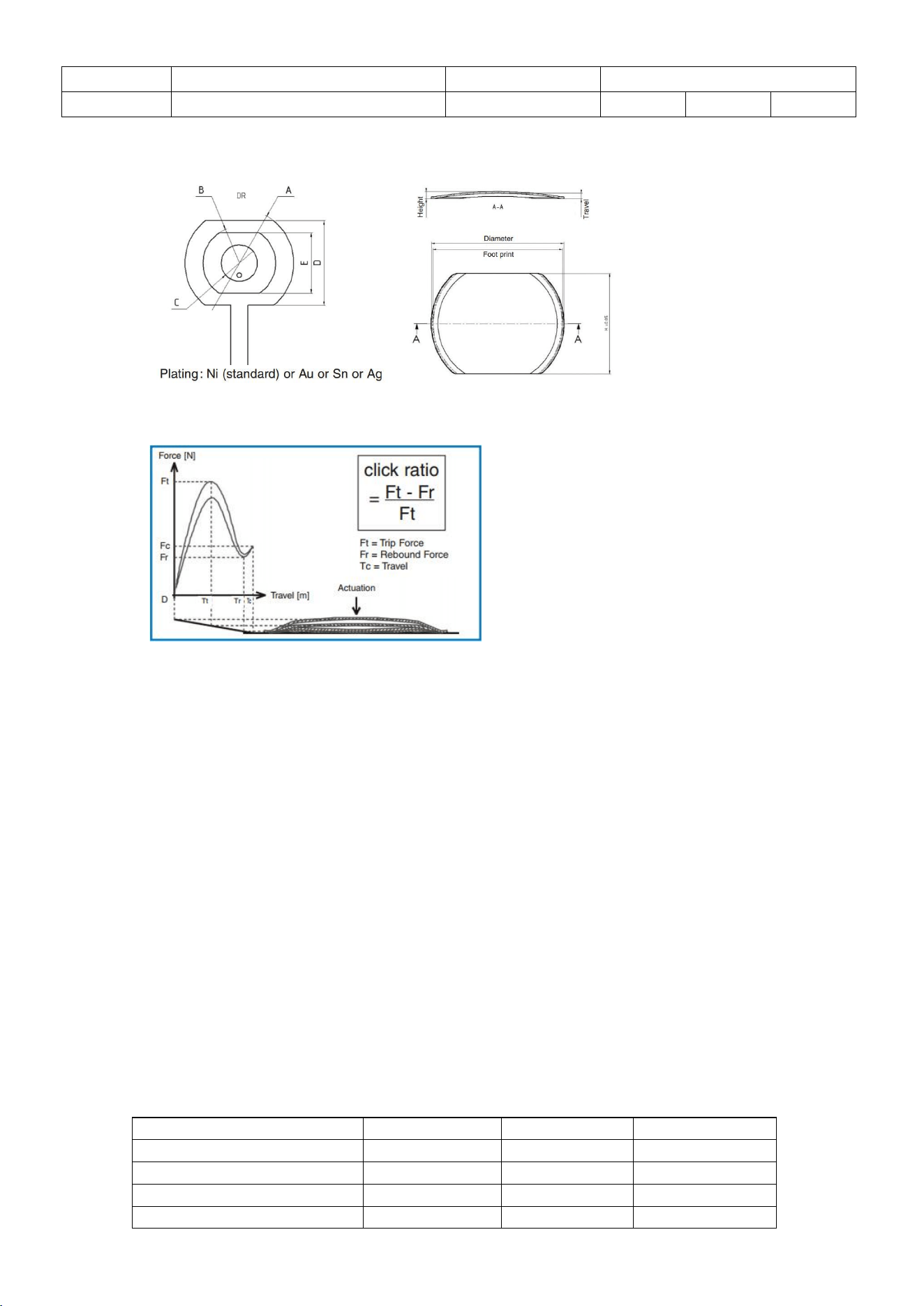
3.3 Dome
Foot print and diameter
Mechanical characteristics
⚫ Trip force: 180±25N
⚫ Rebound force: 80±30N
⚫ Height: 0.23±0.05mm
⚫ Total travel: 0.17±0.05mm
⚫ Diameter: 4±0.05mm
⚫ Square size: 9.90±0.10mm
⚫ Click ratio: 40-70%
⚫ Life cycle: >1’000’000 cycles
3.4 LED
The Green/Yellow/Orange color devices are made with AlGaInP on GaAs substrate Light
Emitting Diode.
All backlights for buttons shall be visible under ambient light conditions of 1000 lux. This requirement
shall still be fulfilled after 40000h of operation.
Characteristics:
Green
Yellow
white
Dominant Wavelength
570nm
587nm
595nm
Luminous
50mcd/m2
80mcd/m2
60mcd/m2
Operating Current
15mA
7mA
15mA
Name
11368793、11368802
NO.
Date
2025-11-06
Ver
A0
page
8/14
3.5 Membrane
Appearance and color define:
⚫ Size: 138*55mm
⚫ Material: Silicone + ABS
⚫ Thickness: 2mm/6mm
⚫ Flame grade: UL94 V0
3.6 Deadman
A general dead man grip shall be available to avoid unintended activation of any button,
The dead man grip shall be activated as soon as the user takes the remote control in the
hand or on the cradle. There shall be no conscious action needed for this.
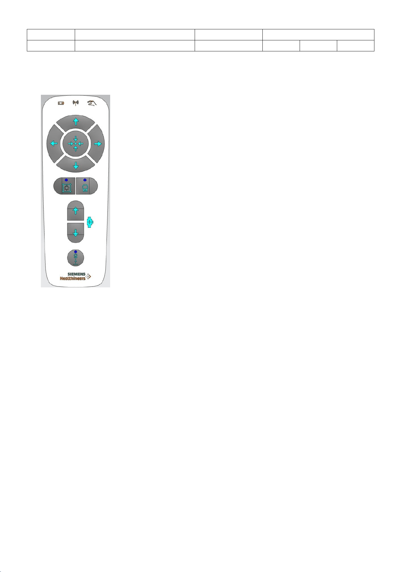
3.6.1 CAP Sensor
CAP sensor shall be used for enable on hand. The effective area is shown as below.
User must make sure the touch area above 10cm2 CAP sensor will be activated.
Name
11368793、11368802
NO.
Date
2025-11-06
Ver
A0
page
9/14
CAP Sensor
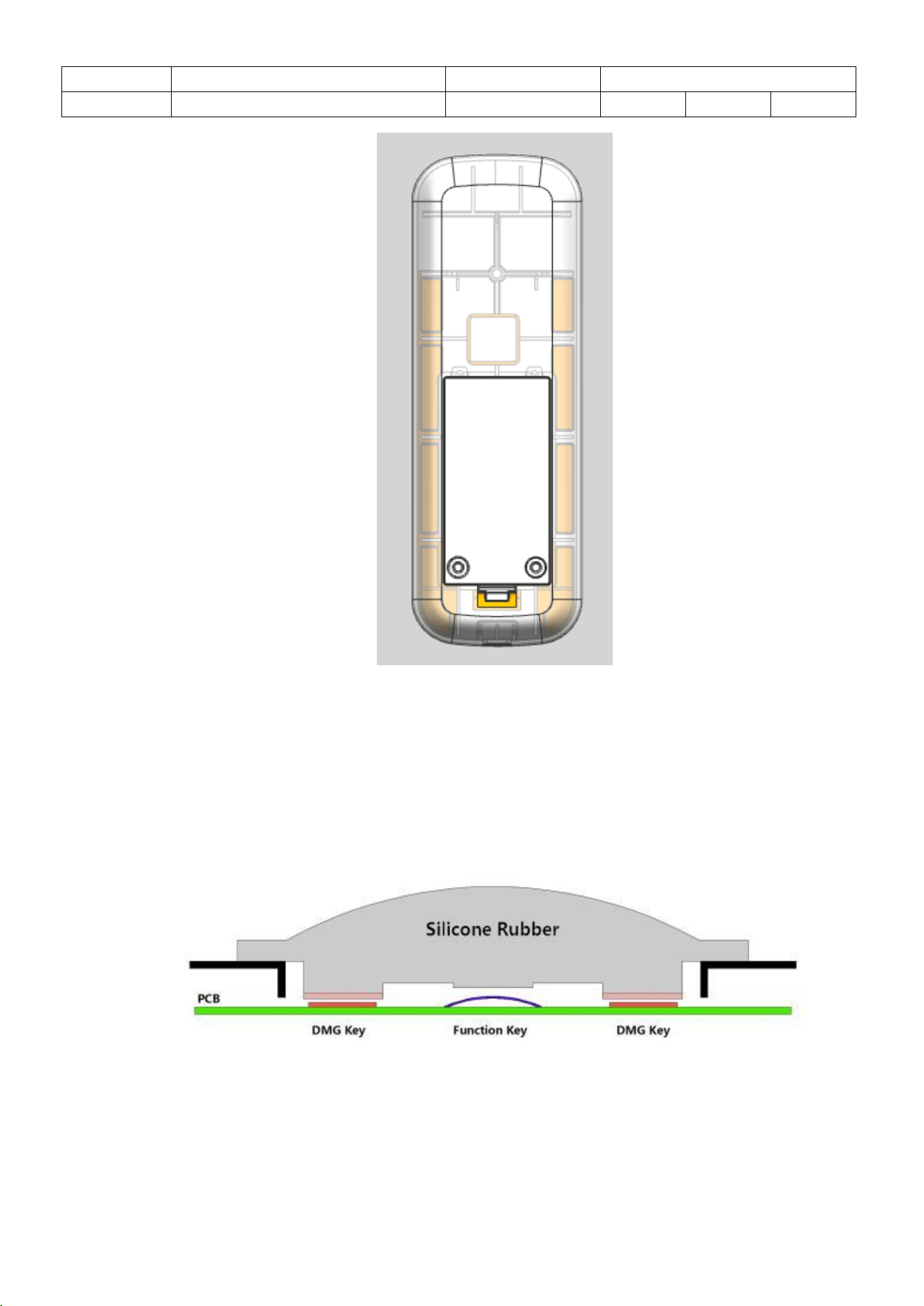
3.6.2 Double Key
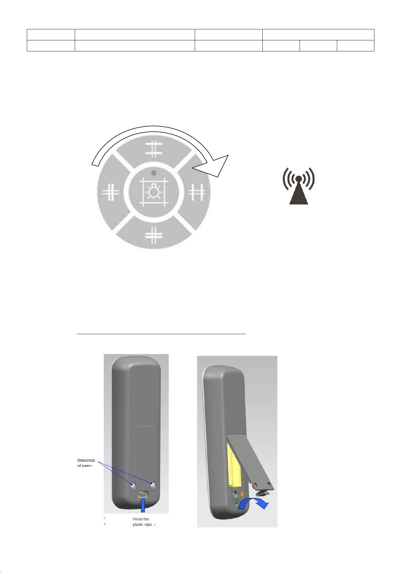
Every key is composed of two independent channels,one is digital and the other is
DMG.
As shown in the figure below, the red DMG keys on both sides, due to their short
travel distance, are prioritized for activation during the downward stroke.
The central blue function button is fully pressed, and the elastic deformation reaches
the limit when the button is pressed down, enabling conduction.
Name
11368793、11368802
NO.
Date
2025-11-06
Ver
A0
page
10/14
3.7 BLE Pairing
Pairing process step:
⚫ System scan and detect RMCs to set pairing with one of it.
⚫ All the RMCs which is received pairing request will turn on four indicators
(up,down,in,out) and waiting for matching.
Signal indicator
⚫ Press the button in turn, when the signal indicator is off, pairing is successful for one of
RMC.
3.8 Battery and Charging
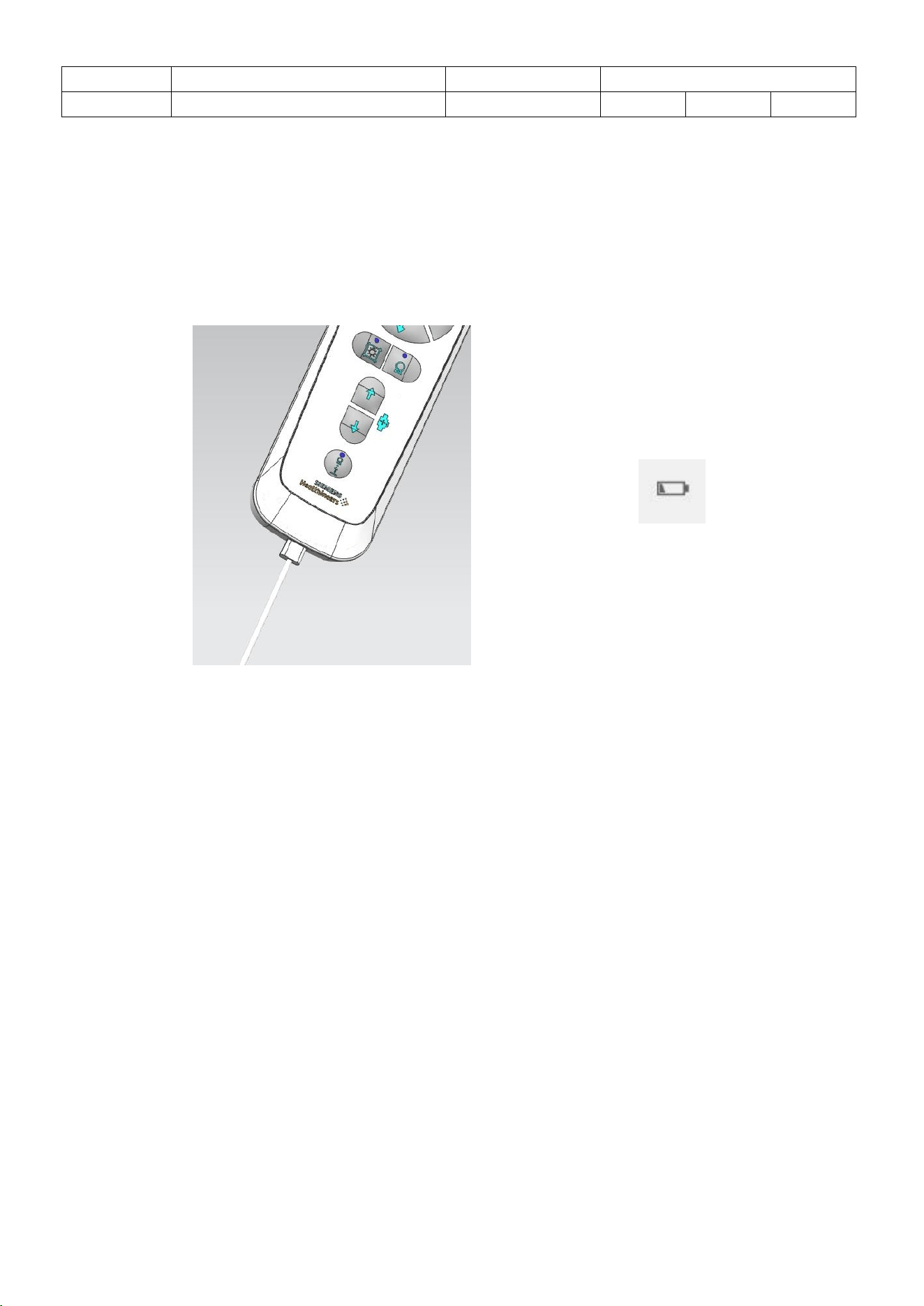
⚫ RMC battery is replaceable as the following show.
⚫ It only can be used Ni-MH type battery which is 1.2V operating voltage in handset.
Charging for Li-Po or alkaline battery is forbidden.
Name
11368793、11368802
NO.
Date
2025-11-06
Ver
A0
page
11/14
⚫ When battery volage is lower than 2.0V,the battery indicator(Red) will be on.
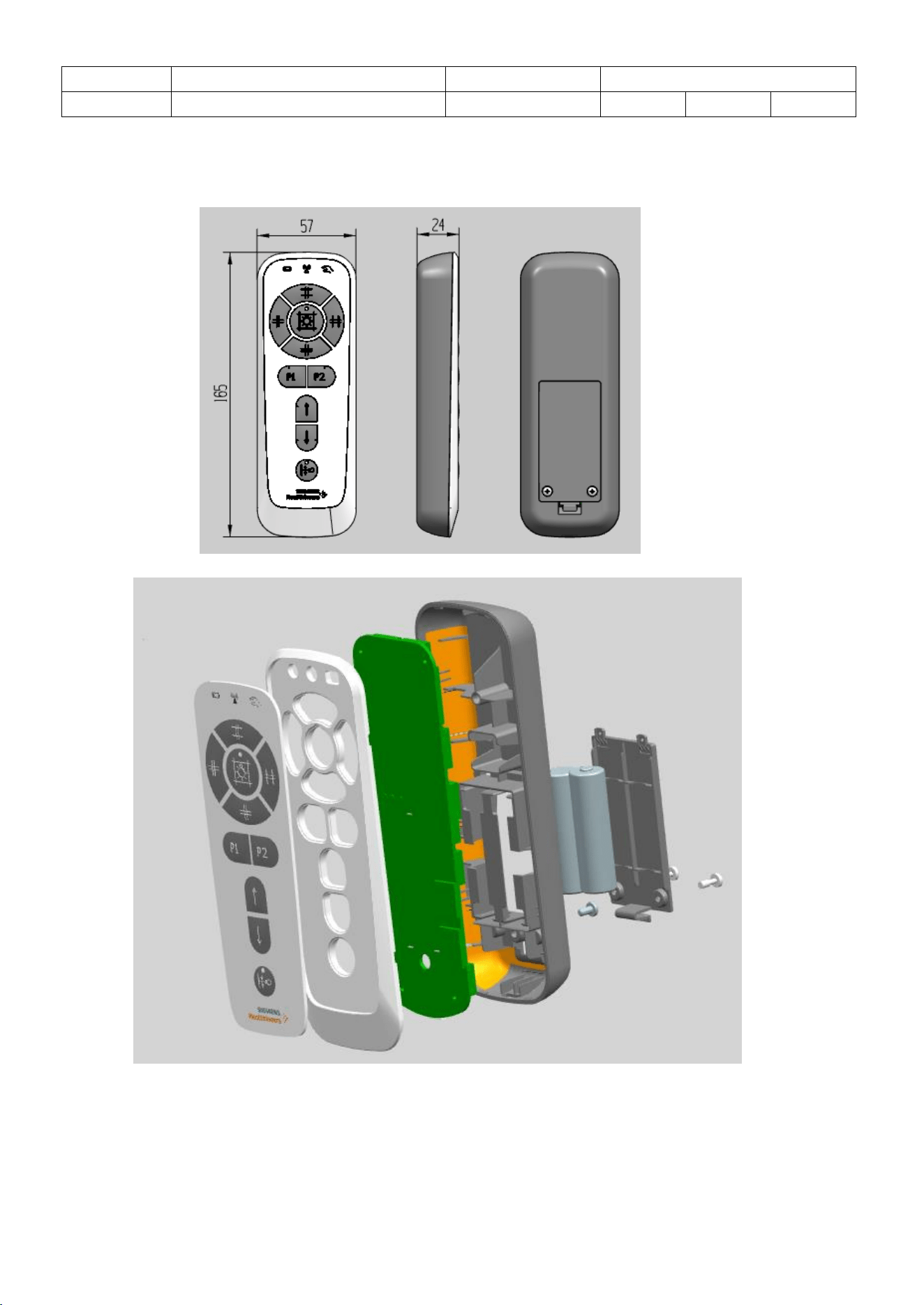
⚫ When battery indicator is on you have to charging from Type-C port, and then the
battery indicator(Yellow) will blink, until indicator keep on ,charging is complete.
⚫ Charging port can be connected to PC USB port or 5V power supply from standard
USB cable.
Battery indicator
3.9 Power save
⚫ If BLE signal is disconnected, handset will go to sleep mode to saving battery
consumption.
⚫ Press any keys, handset will be waken up to connect again, the five indicators which
are up,down,in,out,move,battery will be set on for 0.3 second, but this key action is
ignored.
Name
11368793、11368802
NO.
Date
2025-11-06
Ver
A0
page
12/14
4 Machical specifications
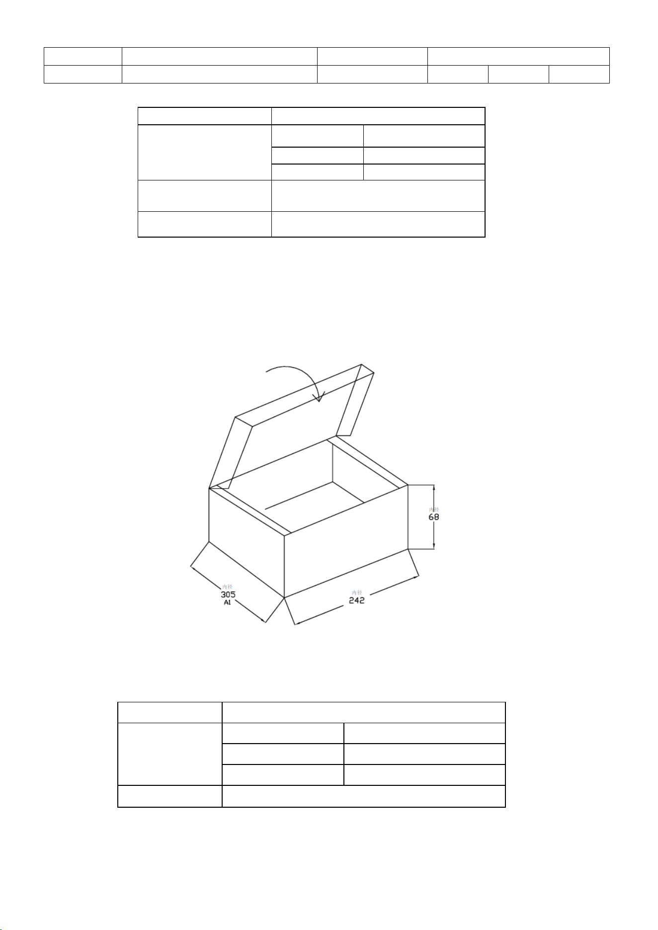
4.1 Outline Dimensions
Unit :mm
Assembly drawing:
Name
11368793、11368802
NO.
Date
2025-11-06
Ver
A0
page
13/14
4.2 Packaging
The carton box figure and list is shown as follows.
Item
Set
Width
55
Depth
22
Height
138
Housing
components
ABS UL94-V0
Net weight
Approximate 120g
Item
Carton Box
Width (mm)
242
Depth (mm)
305
Height (mm)
68
Gross weight
Approximate 515g
Name
11368793、11368802
NO.
Date
2025-11-06
Ver
A0
page
14/14
5 Regulations and standards
5.1 Operation environment
Operation temperature range
0 - 50C
Storage temperature range
-20 - 60C
Operation temperature humidity
20% - 80%
Storage temperature range
20% - 95%
Barometric pressure
700 hPa to 1060 hPa
5.2 Key reliability
Key repeat
1’000’000 times
5.3 Transport conditions
Mechanical class (Transport)
IEC60721 -3-2 2M4
FCC Statement:
Please take attention that changes or modification not expressly approved by the party
responsible for compliance could void the user’s authority to operate the equipment.
This device complies with Part 15 of the FCC Rules. Operation is subject to the following two
conditions:
(1) This device may not cause harmful interference, and
(2) This device must accept any interference received, including interference that may cause
undesired operation.
IC Statement:
This device contains licence-exempt transmitter(s)/receiver(s) that comply with Innovation,
Science and Economic Development Canada’s licence-exempt RSS(s). Operation is subject to
the following two conditions:
(1) This device may not cause interference.
(2) This device must accept any interference, including interference that may cause undesired
operation of the device.
l'appareil contient des émetteurs/récepteurs exempts de licence qui sont conformes aux CNR
exempts de licence d’Innovation, Sciences et Développement économique Canada.
L’exploitation est soumise aux deux conditions suivantes :
(1) l'appareil ne doit pas produire de brouillage,
(2) l'utilisateur de l'appareil doit accepter tout brouillage radioélectrique subi, même si le
brouillage est susceptible d'en compromettre le fonctionnement.
20cm warning for Model No.11368802:
FCC:
This equipment complies with FCC radiation exposure limits set forth for an uncontrolled
environment. This equipment should be installed and operated with minimum distance
20cm between the radiator & your body.
IC:
This equipment complies with IC RSS-102 radiation exposure limits set forth for an
uncontrolled environment. This equipment should be installed and operated with minimum
distance 20cm between the radiator & your body.
ce matériel est conforme aux limites de dose d'exposition aux rayonnements, CNR-102
énoncée dans un autre environnement.cette eqipment devrait être installé et exploité avec
distance minimale de 20 entre le radiateur et votre corps.