User’s Guide & Operator Instructions
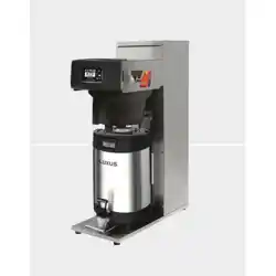
FETCO Hot Tea Brewer Extractor
®
Touch Screen Models
TBS-2111
Description & Features:
-Low profile
-High-Volume hot tea brewer with hot water bypass feature
-Eight programmable recipes: Factory set with two user adjustable permanent recipes
-Six additional recipes may be optionally programmed or hidden
-Individual recipe temperatures can be set by use
-Hot water tank recovers rapidly and may be quickly lowered for specialty recipe temperature with “PURGE” function
-Fully serviceable from the front
THE FOLLOWING CAN BE ACCESSED AND PROGRAMMED:
-BATCH SIZE & BYPASS [Hot Water Bypass] Infinitely variable-factory set at 4.0 liter brew/34% hot water bypass.
-BREW TEMPERAURE
-PURGE TO LOWER BREW TEMPERATURE: OPTIONAL SELECTION! Operator may use PURGE touch key.
Holding the key for the maximum five seconds releases 150 cc/4 fl.oz hot tank water to reduce brew temperature.
-PULSE BREW: Using information entered, the software calculates how much water to dispense for brew and for hot
water “bypass”. The total dispense time is divided into on/off cycles that dispenses the exact volume of water and
pauses to drain the brew basket. Pulse brew can be set by the operator. Factory set is four on/off fill/drain cycles.
Controls automatically cycle valves to dispense the correct amount of water set in the recipe.
-RECIPES are all adjustable. Recipes 1&5 are permanent; recipes 2, 3, 4, 6, 7, 8 can be programmed or hidden.
See pages 6-13 for programming, adjustments and calibration.
CONTACT INFORMATION
FETCO® FOOD EQUIPMENT TECHNOLOGIES COMPANY
600 ROSE ROAD
LAKE ZURICH • IL • 60047-0429 • USA
Product made in USA
INTERNET: www.fetco.com
PATENTS:https://www.fetco.com/pl,pages,patents,74.html
©2016-2020 FOOD EQUIPMENT TECHNOLOGIES COMPANY
PHONE: (800) 338-2699 (US & CANADA)
(847) 719-3000 (All Countries and International)
FAX:(847) 719-3001
EMAIL:sales@fetco.com
orders@fetco.com (to order parts and equipment)
techsupp[email protected]om (all service queries)
P152 rev.003 August 2021
HOT TEA BREWER TBS-2111
fetco.com
2
TABLE OF CONTENTS
OPERATIONAL DESCRIPTION .................................... 3
BASIC SCREENS .......................................................... 3
Instructions To Access The Programming Menu ........... 5
PROGRAM ..................................................................... 6
GENERAL ....................................................................... 8
INPUTS ........................................................................... 8
HOW TO CALIBRATE THE FLOW RATE ................... 10
OTHER ......................................................................... 13
ERROR CODES ........................................................... 14
Parts Drawings And Wiring Diagrams .......................... 18
Hot Water Faucet Installation Instructions ................... 23
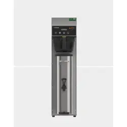
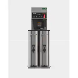
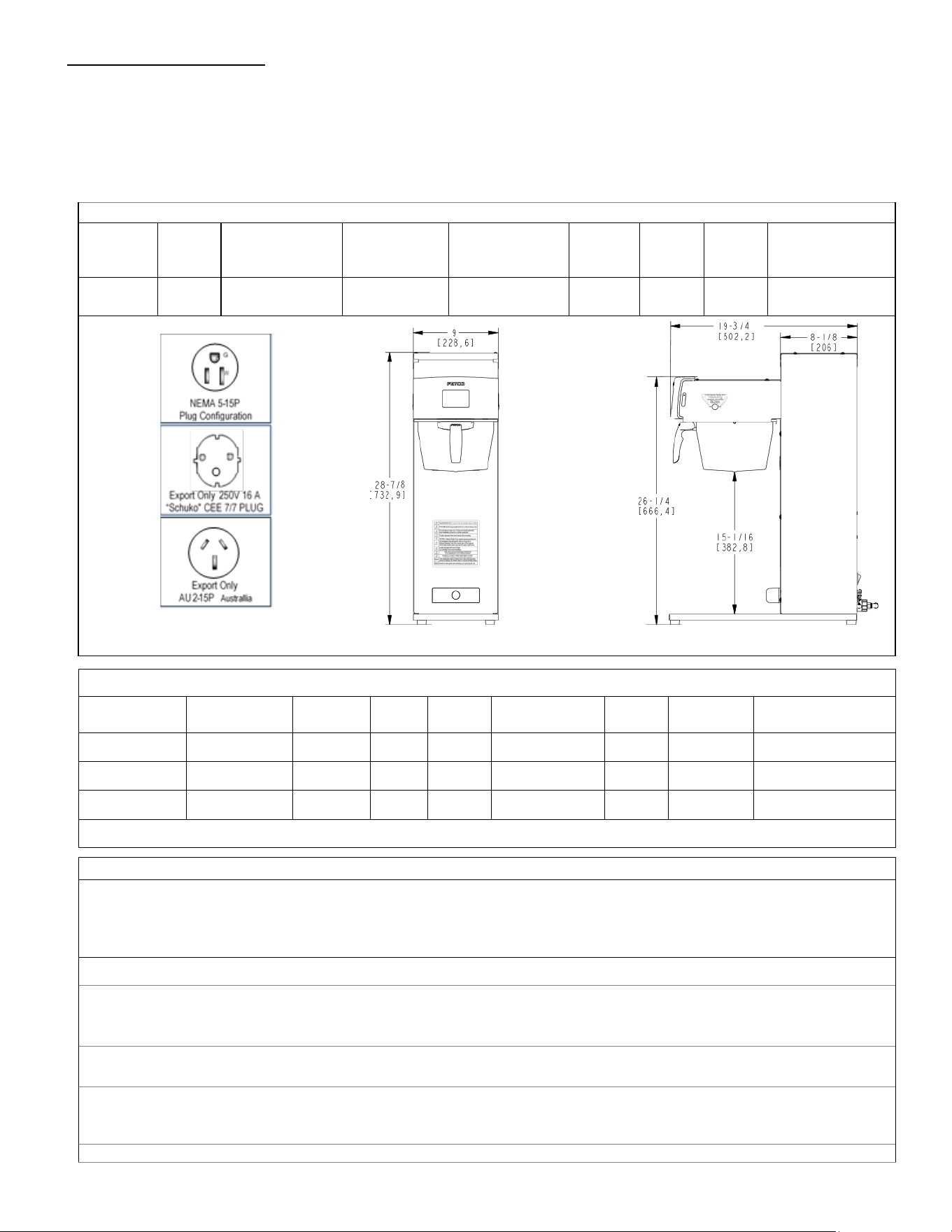
Specifications and Requirements
FETCO TBS-2111 Hot Tea Brewer with Bypass (hot water bypass)
TBS-2111-Capacities & Measurements
Brewer Height
Width
No hot water
faucet
Width
One hot water
faucet
Width
Two hot water
faucets
Depth
Empty
Weight
Filled
Weight
Hot Water Tank
Capacity
TBS-2111
733 mm
29 inch
229 mm
9 inch
292 mm
11.5 inch
356 mm
14 inch
502 mm
20 inch
14.4kg
32 lb
26.3kg
58 lb
11.9 liter
3.1 gallon
TBS-2111-Dimensions & Utility Connections
Note: dimensions in parenthesis are in millimeters Drawing number 1201.00041.00
TBS-2111-Water Requirements
Water Connection: Inlet: 3/8 inch male flare fitting
Mains Pressure: 0.31-0.517 mPa 0.34MPa/50PSI preferred (45-75 psig ).
Minimum Flow Rate: 5.7 liter/minute (1½ gpm). Optimal water hardness between 125-250 TDS (6-13 grain)
All commercial hot water dispensers to be supplied with filtered water from mains
The following are the factory settings—and ranges of variables that are adjustable:
Brew volume: 6 liter Batch: (default all recipes: 4 liters brew+34% bypass)
RANGE [0.50-6.00 liter BREW] [0-40% BYPASS]
*Brew volume per hour based on factory default of 11:43 minutes/6 liter 30 liters or 8 gallons/hour
Total Brew Cycle-Factory setting: 10:52 minutes [6 minute brew time+1.5 minute drip delay+2minute bypass]
RANGE [1:00-12:00 minute BREW] [0:30-12:00 minute BYPASS DELAY]
Temperature Control—as set by factory: 90°C inside hot water tank (at sea level).
-RANGE User selectable: 77-97°C/170°-207°F
-Brew Temperature may be individually set for each of the eight recipes.
Coffee Filter Size: 15” X 5 ½ ”– standard FETCO # F001
TBS-2111-Electrical Configurations
Configuration
Code
Heater
Configuration
Voltage Phase Wires
Electrical
Connection
KW Amp Draw
Brew
Per hour*
T211151 1 X 1.7kW 100-120 single L, N, G
NEMA 5-15
1.3-1.8 12.3-14.7 4.4 gal/16.5 liters
T211191 1 X 3KW 200-240 single 2+G
Shuko
cord and plug
3.1 10.8-12.9 30 liters/8 gallon
T211192 1 X 2.3KW 200-240 single L,N,PE
Australian
cord and plug
2.5 19.8 30 liters/8 gallon
Please see wiring diagrams located in back pages for installation notes.
Go to fetco.com for the latest versions of all information Page 3 User Guide & Operator instructions P152 rev.003 August 2021
90°C
90°C
[[¯]] 6.00L
90°C
[[¯]] 6.00L
90°C
[[¯]] 6.00L
90°C
[[¯]] 6.00L
<5 sec
5
6
7
8
90°C
90°C
[[¯]] 6.00L
90°C
[[¯]] 6.00L
90°C
[[¯]] 6.00L
90°C
[[¯]] 6.00L
<5 sec
1
3
2
4
90°C
90°C
[[¯]] 6.00L
90°C
[[¯]] 6.00L
90°C
[[¯]] 6.00L
90°C
[[¯]] 6.00L
<5 sec
1
3
2
4
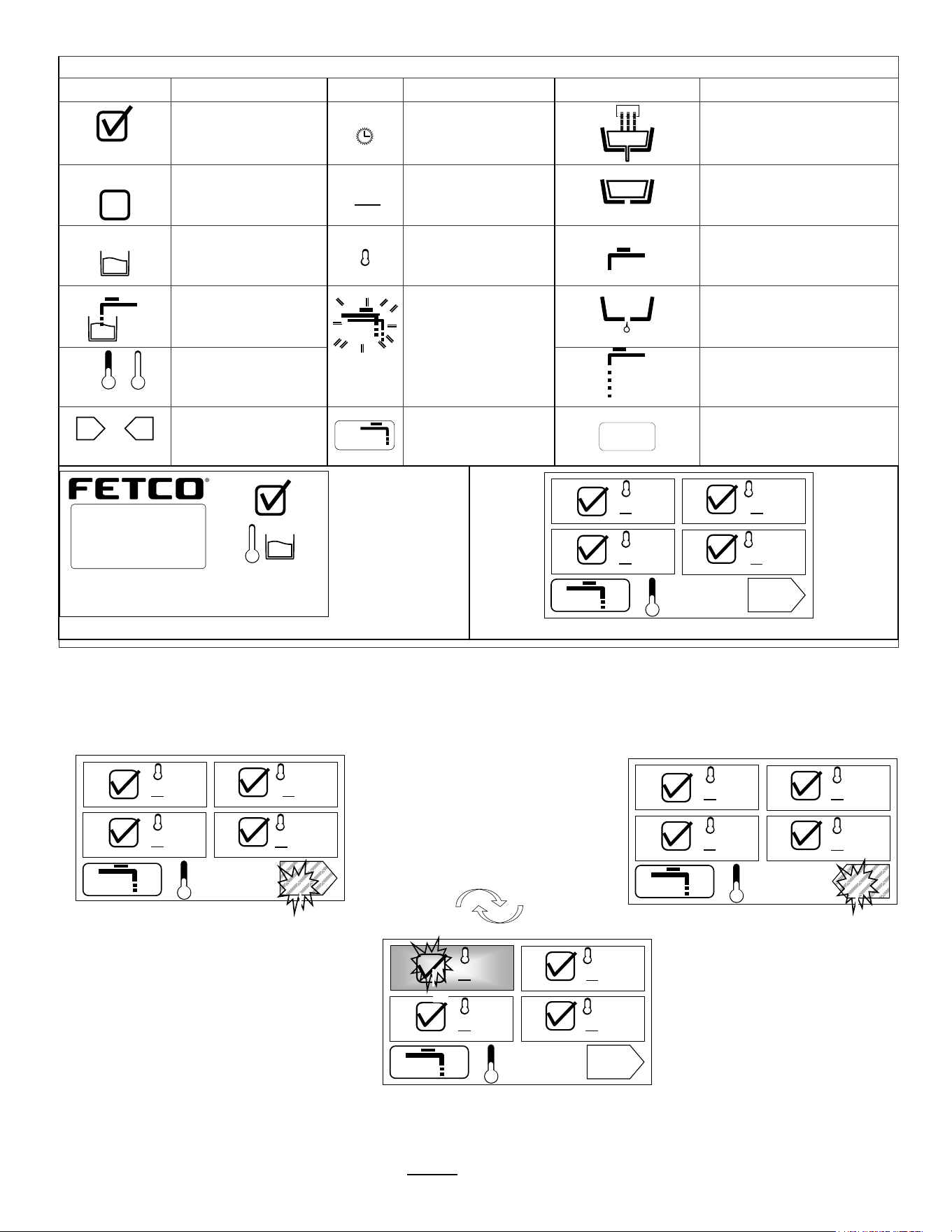
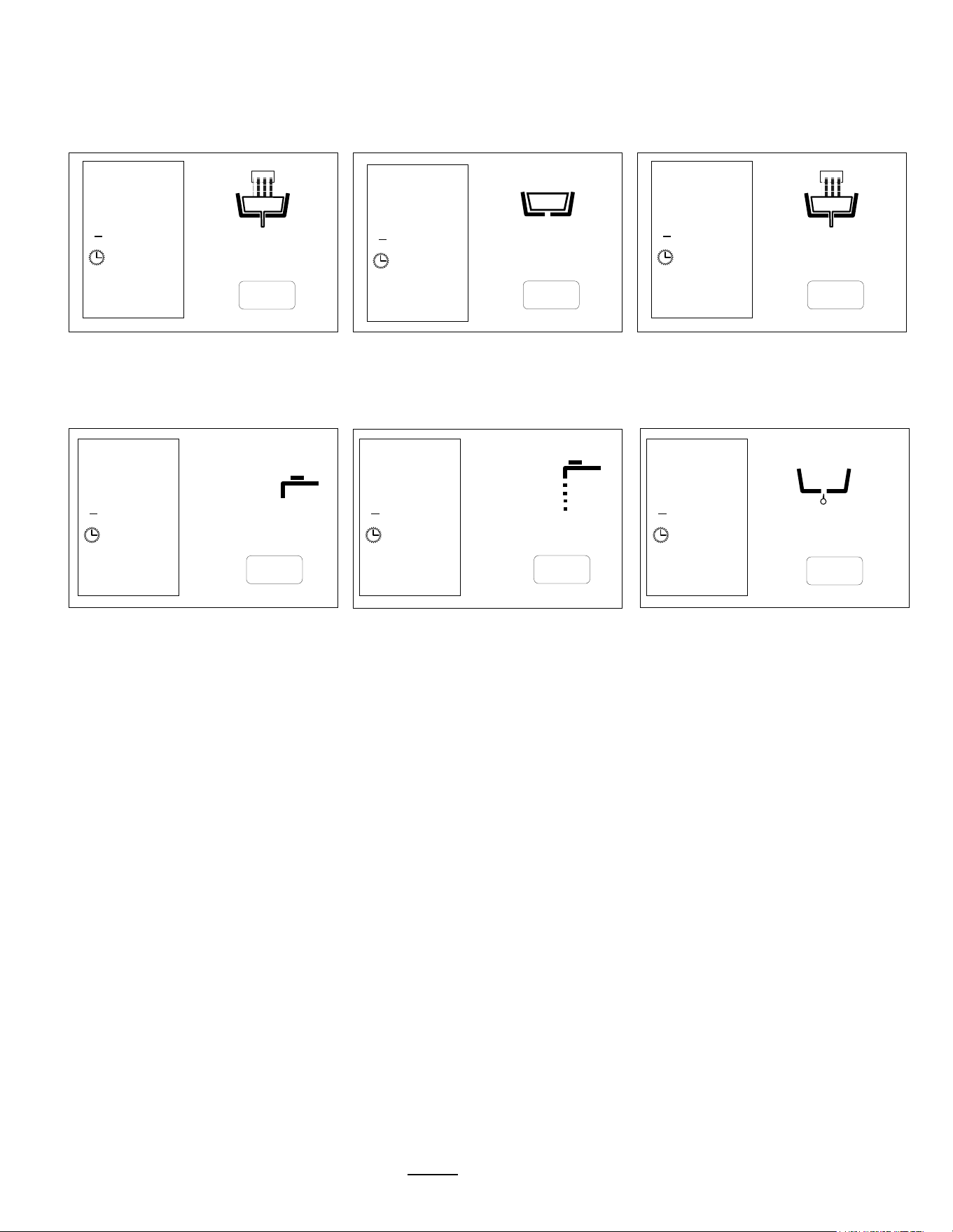
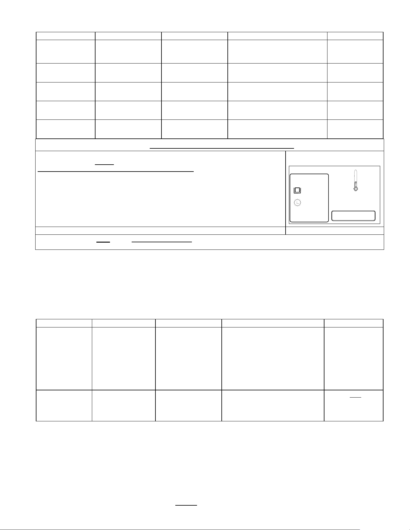
ICON Definition Table
ICON
Definition
ICON
Definition
ICON
Definition
Ready to brew
Brew time
Brew valve cycle is “open”
and is cascading water.
Brewer not ready
for this recipe
(may be overridden)
[[¯]]
Batch Size
Brew valve paused.
Pulse brew-drain
Hot water tank -
filled
Temperature icon
Waiting
Hot water bypass ready to
start- paused (delay)
Hot water tank –
filling/refilling
When blinking:
Hot water tank
temperature over
setting.
Purge to reduce
water temperature
Drip-out
/
Heating/
At Temperature
Hot Water bypass “ON”
or
Toggle from menu
screen 1-4 to 5-8
Press purge key
to reduce water
temperature
“STOP”
Brewer is
“READY”
Hot water tank
is heated and full
Hot water tank
temperature (°C)
FETCO TBS-2111 home screen
Menu 1 of 8
Menu 3 of 8
Purge Key
FETCO TBS-2111 recipe screen
Menu 2 of 8
Menu 4 of 8
Continue to
Menus 5-8
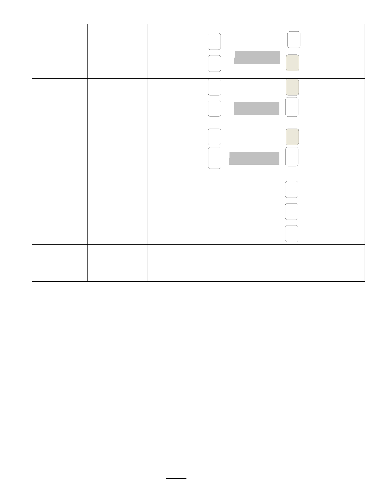
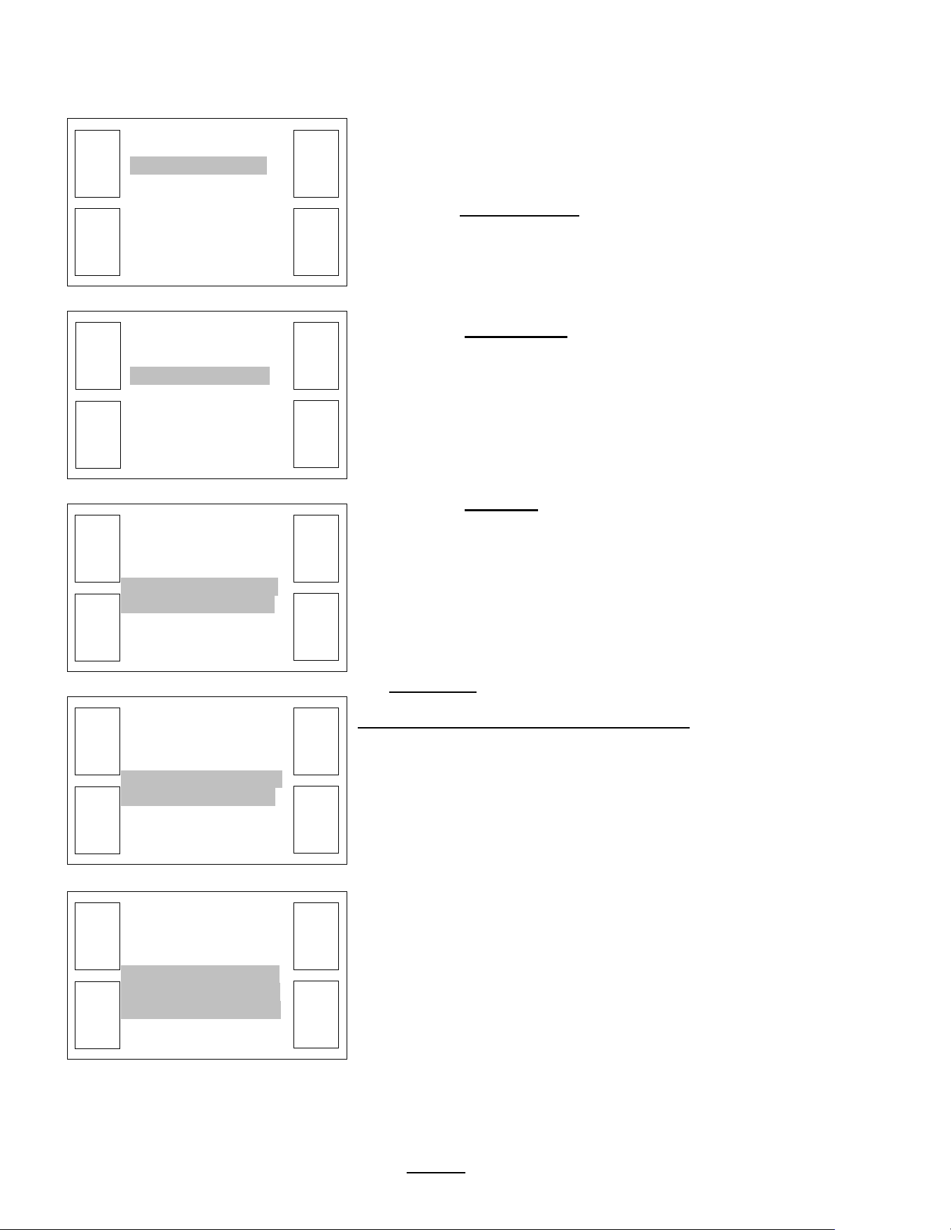
Operational Description
Basic Screens
:Recipes, Brew, Starting Menus and General Brewing Sequence
8 DEFAULT RECIPE SCREENS –Toggle button between screens to access recipes 1-4 and 5-8
TOUCH AND HOLD 2-3 seconds
Toggle to recipe-choose 1-8
Menus 1-4
Touch right pointing arrow for 5-8
Menus 5-8
Touch left pointing arrow to go back
Touch Menu ICON #1 to START BREW
Touch for 2-3 seconds to begin brew.
Have container under brew funnel
lL
<5 sec 90°C
90°C
[[¯]] 6.00L
90°C
[[¯]] 6.00L
90°C
[[¯]] 6.00L
90°C
[[¯]] 6.00L
1
3
2
4
STOP
TBS_2111
© 2016 all rights reserved
XTS
EXTRACTOR
TOUCHSCREEN
90°C
<5 Sec
Go to fetco.com for the latest versions of all information Page 4 User Guide & Operator instructions P152 rev.003 August 2021
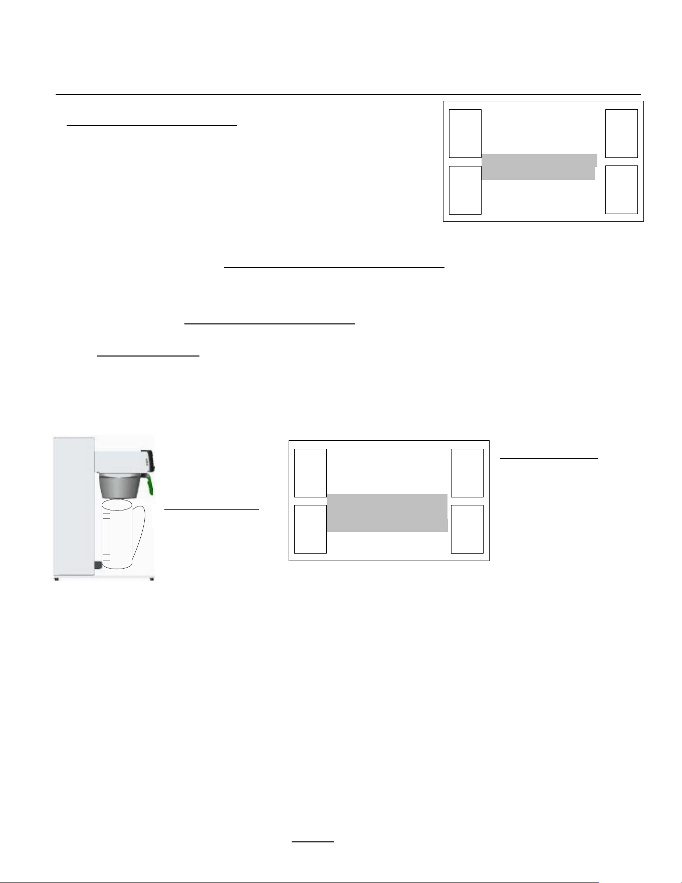
lL
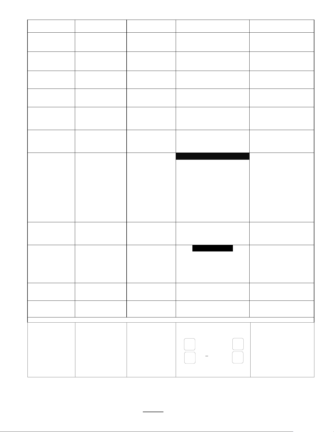
Screens with informational icons shown for factory set recipe #1-(See Icon table for more information)
Pulse Brew icon
brew in progress
Brew-valve is open in pulse brew
mode.
Valve opens-closes for pulse brew
Pulse Brew icon
brew in progress
paused icon brew-valve is closed
Icons showing open state in pulse
brew mode-(brew-valve reopened)
Brewing and Pause icons cycle…
Left box shows recipe settings Factory set: 4 on/off pulse cycles
Brew completed. 1:00 min bypass delay
for drip-out and hot water tank recovery
Bypass is cycling and is turned ON
Drip Delay
1:30 minutes
User can determine any bypass delay
See following page for programming
At 0:00, recipe screen will refresh
Icons shown for factory set recipe #1
9:30…
STOP
1
[[]] 6.00L
9:30
°C 90°C
…8:41…
STOP
1
[[]] 6.00L
9:30
°C 90°C
...7:48
STOP
1
[[]] 6.00L
9:30
°C 90°C
…2:30…
1
[[]] 6.00L
9:30
°C 90°C
…3:30…
1
[[]] 6.00L
9:30
°C 90°C
1
[[]] 6.00L
9:30
°C 90°C
…1:30
STOP
STOP
STOP
Go to fetco.com for the latest versions of all information Page 5 User Guide & Operator instructions P152 rev.003 August 2021
Instructions to access the Programming Menu
To access programming
Power-off then power-on the equipment…
1) Switch TBS-2111 power “OFF”
and then
2) Turn main power switch to “ON”
(switch is located on the lower back)
The touch screen will illuminate.
Immediately
Touch and hold finger to enter programming
In 5
-8 seconds “PASSWORD” screen will
appear.
ENTER 0 0 0 0 and press “ENTER”
“PROGRAM”
will appear (in first column below
)
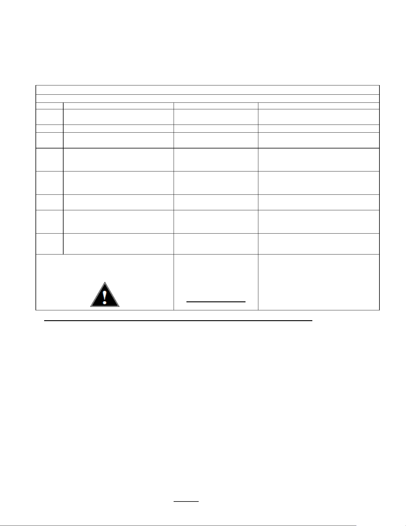
Programming-category screens: Menu Tree Menu
Features: Batch Parameters
XTS Main Menu
Menu Chart
|
|
|
|
|
PROGRAM
GENERAL
INPUTS
OUTPUTS
OTHER
|
|
|
|
|
Batch 1
<Batch Summary>
Ready Temp.
<+/- 2 °C>
Display Inputs
<Inputs Summary>
Brew Valve
<Calibrate/Test>
Error Codes
<Display Errors>
|
|
|
|
|
Batch 2
<Batch ON/OFF>
Brew at Temp
<AUTO>
Calibrate Touch
Screen
Bypass Valve
<Calibrate/Test>
Copy Program
<From SD to B.>
|
|
|
|
Batch 3
<Batch ON/OFF>
Units of Measure
For Temperature & Volume
Fill Valve
<Test>
Upload LOGO
|
|
|
|
Batch 4
<Batch ON/OFF>
LOGO Timeout
<1:00 mm:ss>
Heater
<Test>
Reset to Factory
<Restore to Default>
|
|
|
Batch 5
<Batch Summary>
Buzzer
<Test>
Counters
<Display Total Counter>
|
|
|
Batch 6
<Batch ON/OFF>
Screen
<Screen Contrast>
Firmware
<Firmware Version>
|
|
Batch 7
<Batch ON/OFF>
DEMO Mode
|
|
Batch 8
<Batch ON/OFF>
Password
|
Batch Copy
<Copy From B.>
<GENERAL>
<Ready Temp>
»
«
▲
▼
< Program >
< Batch 1 >
»
«
▲
▼
<INPUTS>
<Display Inputs>
»
«
▲
▼
<OUTPUTS>
<Brew Valve>
»
«
▲
▼
<OTHER>
<Error Codes>
»
«
▲
▼
TBS_2111
©2016 all rights reserved
XTS
™
EXTRACTOR
TOUCHSCREEN
90°C
TOUCH
and
HOLD
Go to fetco.com for the latest versions of all information Page 6 User Guide & Operator instructions P152 rev.003 August 2021
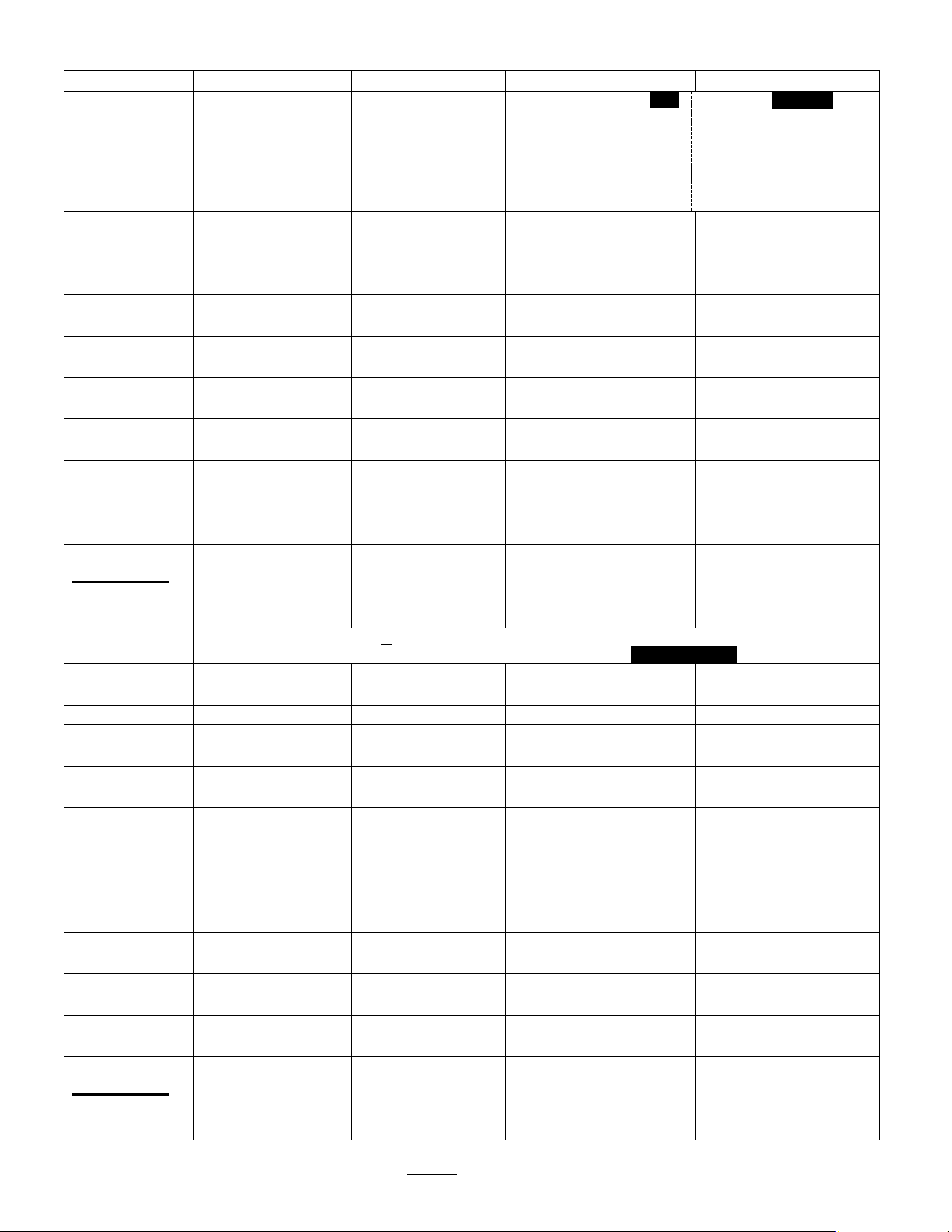
PROGRAM
Programming Items
Factory set Default
Programming Range
Notes
Batch 1 *
• Batch Summary
Display Summary
Batch Summary
Batch Name
Brew Temp.
Brew Volume 4.00
Brew Time
Bypass Vol. 34
Total Time
1
90°C
Liter
6:00
%
9:30
Summary-continued
Bypass Delay
Number of Pulses
Prewet Percent
Prewet Delay
Drip Delay
Alarm At End
1:00
4
0%
0:00
1:30
NO
• Batch Temp
90 °C
90 °C
|__________[]______|
77 97
This sets the brew
temperature for batch-1
• Brew Volume
4.00 liter
[ 0.50-4:00]
4.00 liter
|__________[]_______|
0.50 10:00
Volume of hot tea (tea to
hot water bypass [2:1])
• Bypass Percent
34%
34%
|______________[]____|
0:00 40
Volume of HOT water to
add to hot brew
• Bypass Delay
1:00 mm:ss
1:00 mm:ss
|_[]_______________|
0:00 12:00
Allows for hot water tank
recovery
• Prewet Percent
0%
0 %
|_[]_______________|
0 15
Prewetting helps stabilize
ground coffee
Pause after prewet
spray completes
• Prewet Delay.
0:00 mm:ss
0:00 mm:ss
|_[]_______________|
0 1
This feature appears
ONLY if Prewet >0:00
• Brew Time
6:00 mm:ss
6:00 mm:ss
|________[]_________|
1:00 12:00
• Nr Of Pulses
4
4
|_____[]___________|
1 30
This is a
Safety Feature
• Drip Delay
1:30 mm:ss
1:30 mm:ss
|_____[]___________|
0:30 10:00
NEVER remove brew
basket during drip-out
• Alarm at End
NO
NO
|______________[]__|
YES ……… NO
Notice
*Batches 1 & 5 are mandatory and are always permanently selected
Batch 2,3,4,6,7&8 may each be selectively hidden with the Batch ON/OFF selector screen
Batch 2
• Batch ON/OFF
ON
ON
|__[]_______________|
ON OFF
• Batch Summary
Display Summary
[See BATCH 1]
• Batch Temp
90 °C
90 °C
|__________[]______|
77 97
This sets the brew
temperature for batch-1
• Brew Volume
4.00 liter
[ 0.50-4:00]
4.00 liter
|__________[]_______|
0.50 10:00
Volume of hot tea (tea to
hot water bypass [2:1])
• Bypass Percent
34%
34%
|______________[]____|
0:00 40
Volume of HOT water to
add to hot brew
• Bypass Delay
1:00 mm:ss
1:00 mm:ss
|_[]_______________|
0:00 12:00
Allows for hot water tank
recovery
• Prewet Percent
0%
0 %
|_[]_______________|
0 15
Prewetting helps stabilize
ground coffee
Pause after prewet
spray completes
• Prewet Delay.
0:00 mm:ss
0:00 mm:ss
|_[]_______________|
0 1
This feature appears
ONLY if Prewet >0:00
• Brew Time
6:00 mm:ss
6:00 mm:ss
|________[]_________|
1:00 12:00
• Nr Of Pulses
4
4
|_____[]___________|
1 30
This is a
Safety Feature
• Drip Delay
1:30 mm:ss
1:30 mm:ss
|_____[]___________|
0:30 10:00
NEVER remove brew
basket during drip-out
• Alarm at End
NO
NO
|______________[]__|
YES ……… NO
Go to fetco.com for the latest versions of all information Page 7 User Guide & Operator instructions P152 rev.003 August 2021
.PROGRAMMING MENU-Continued
PROGRAM
Continued
Programming
Items
Factory set Default Programming Range Notes
Batch 3
(See Batch 2)
Batch 4
(See Batch 2)
Batch 5
(See Batch 1)
Batch 6
(See Batch 2)
Batch 7
(See Batch 2)
Batch 8
(See Batch 2)
Batch Copy
Copy From Batch
COPY from B.(1-8)?
Copy To Batch
COPY to B.(1-8)?
Copy?
B1B2?
(example)
NO
|_______________[]__|
YES NO
*Batch 1& 5 are mandatory and cannot be disabled. Other batches can be disabled [“hidden”], and removed from display
Programming Batch Temperature
Individual temperature settings can be programmed for all eight recipes. This accommodates many different brew
temperature requirements of the tea product used. The hot water tank temperature automatically sets to the lowest
programmed recipe setting. If a brew is started for a higher temperature setting, the brewer will pause and quickly heat
the hot water tank to the temperature setting of the recipe before starting the brew. This is rapid: taking only minutes.
Tank temperature is too low for brew setup
1) If the tank temperature is LOWER than the temperature setting—the brewer will display the “Not Ready” icon:
The hot water tank will quickly reheat and the “Ready” icon will display when heated to the set temperature:
Tank temperature is too high for brew setup
2) If the tank temperature is HIGHER than the temperature setting—the brewer will flash the “PURGE” icon:
“PURGE” to cool feature
Purge is drawing a small amount of hot water from the hot water tank—the temperature of the tank is automatically
reduced by cool, fresh refill water from the mains. When the “PURGE” icon is activated for 5 seconds approximately
≈150ml/4 fl.oz hot water is released as bypass water and the tank temperature is reduced.
a) The hot water tank temperature can be quickly lowered by touching the “PURGE” icon for five seconds.
The single purge is adequate for most adjustments.
Note: the purged water increases the contents of the dispenser. The 150ml released is a negligible addition for most
brews—but should be noted for dispensers without headspace or for multiple purges
b) Water may be drawn from the hot water service faucet to lower hot water tank temperature.
The “PURGE” function is preferred as it offers better control.
c) Tank temperature override
The brew can be started at the high temperature by touching and holding the “START” icon to override the icon.
The brew may be exposed to some brewing water that is higher than temperature setpoint.
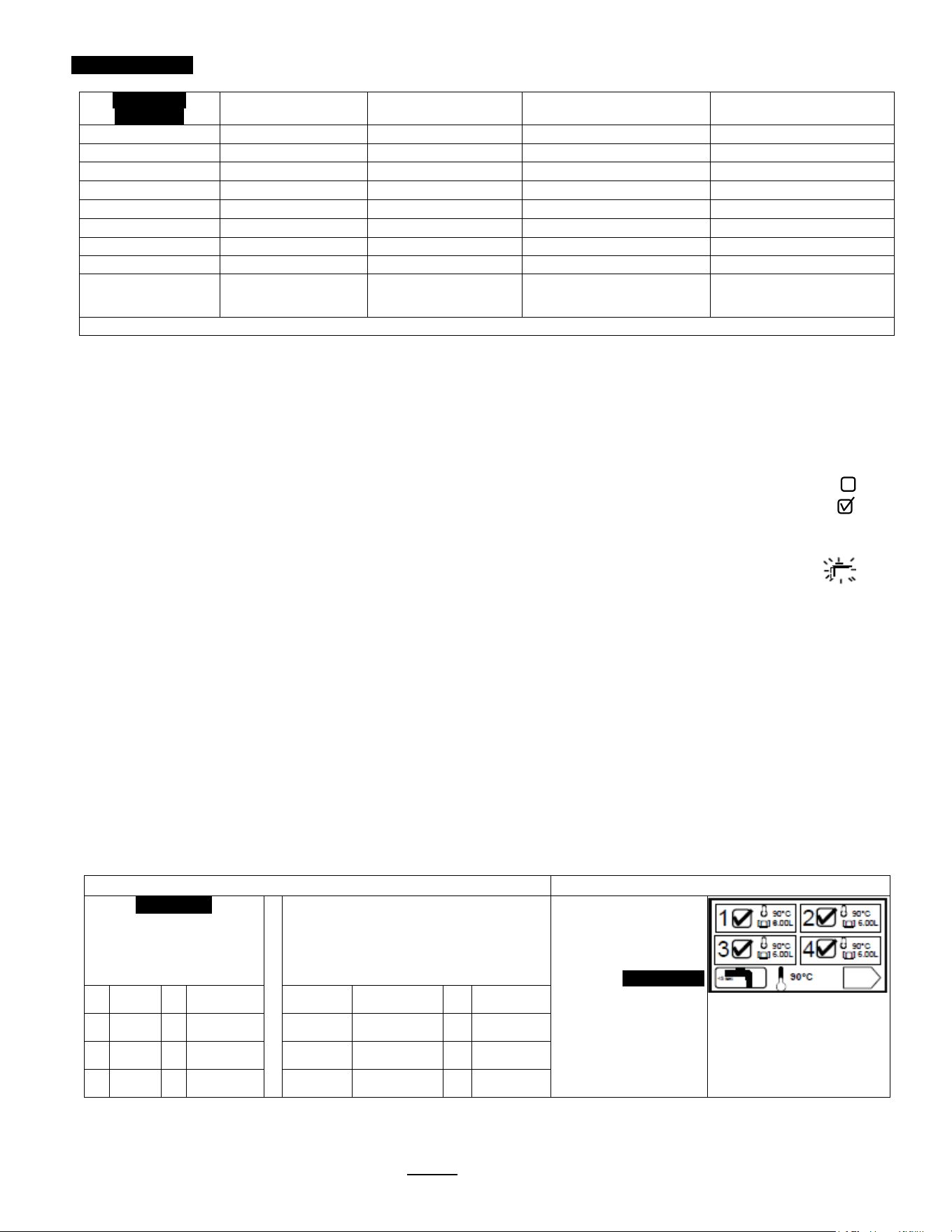
Recipe temperature setting table
Purge to lower brew water temperature
GENERAL
Factory Set
Temperature Summary
SETTINGS BY USER
Temperature Summary as Set By
User
Fill this in and save for future
reference
Recipes show the
temperature setting. These
can be set by user from 80-
97°.
PURGE Icon
Touch the purge icon for 5
sec. This will lower hot water
tank temperature 3-4
degrees
1 90°C 5 90°C 1 5
2 90°C 6 90°C 2 6
3 90°C 7 90°C 3 7
4 90°C 8 90°C 4 8
.
Go to fetco.com for the latest versions of all information Page 8 User Guide & Operator instructions P152 rev.003 August 2021
STOP
1
6.00L
87°
10:36 (<set point)
°C 90.0
GENERAL
Programming Items
Factory set Default
Programming Range (display)
Notes
Ready Temp
+ / - 2°C
+ / - 2°C
|______[]__________|
1 5
Range when
“READY” icon
will show
Brew at Temp.
“OFF” allows brewing
at any temperature.
AUTO
AUTO
|____________[]___|
OFF AUTO
SEE NOTE!
(Below)
Units of Meas.
<Toggle Temp-Vol.>
• Temperature
°C
°C
|____________[]___|
°F °C
<Toggle Temp-Vol.>
• Volume
Liters
Liters
|_____________[]__|
Gallons Liters
Logo Timeout 1:00 mm:ss
1:00 mm:ss
|_[]_______________|
0:00 5:00
NOTE: FOR BREW AT TEMPERATURE DEFINITIONS
BREW AT TEMP: AUTO
(DEFAULT: FACTORY PROGRAMMED INTO BREWER)
This allows the “BREW START” to active.
If the hot water tank is at the selected temperature—the brew will start.
If the temperature is too low—not at the selected temperature, the brewer will wait until the
proper temperature is reached and then will automatically begin brewing.
A thermometer icon screen will display showing the tank temperature. (example: right)
IMPORTANT:
ALWAYS have dispenser(s) under the brew baskets when in the BREW AT TEMP mode.
BREW AT TEMP: OFF USER SELECTABLE
Allows brewing at any temperature. (Not recommended-it is possible to start brew with brew water at incorrect temperature.)
INPUTS
Programming Items
Factory set Default
Programming Range (display)
Notes
Display Inputs
• Input Summary
Brew Basket Sensor
Liquid Level Sensor
Temperature Probe
SD Card
Cal. Touch Scr
Calibrate
Calibrate
________________[]____
YES NO
If Yes:
Follow directions
on the touch
screen
Go to fetco.com for the latest versions of all information Page 9 User Guide & Operator instructions P152 rev.003 August 2021
TEST
CAL
▲
TEST
CAL
TEST
CAL
▲
Cal
Time
Rem.
1:00
OUTPUTS
Programming Items
Factory set Default
Programming Range (display)
Notes
Brew Valve
Calibrate/Test
• Brew Valve (Press to test)
< OUTPUTS >
< Brew Valve >
< Calibrate/Test>
Cal Test
Press To Cal/Test
BASKET IN PLACE
TEMP READY
Runs valve to verify
flow. Have container
under brew basket!
Brew Valve-
CALIBRATE
• Brew Valve
< OUTPUTS >
< Brew Valve >
< Calibrate/Test>
Cal Test
Press To Cal/Test
BASKET IN PLACE
TEMP READY
See pages 10-12
for
detailed calibration
procedure and
screens
BYPASS Valve-
CALIBRATE
• BYPASS Valve
< OUTPUTS >
< Brew Valve >
< Calibrate/Test>
Cal .
To Stop press Cal.
CAL IN PROGRESS
See pages 10-12
for
detailed calibration
procedure and
screens
Fill Valve
• Fill Valve Test
(Press to test)
TEST
Press To Test
Operates fill valve.
Have container under
both brew baskets!
Heater
• Heater Test (Press to test)
TEST
Press To Test
Energizes Heater(s)
Use for servicing.
Buzzer
• Buzzer Test (Press to test)
TEST
Press To Test
Confirms “BEEP”
Use for servicing.
Screen
• Screen Contrast Contrast
8
|____________[]____|
1 10
• S. Brightness
Brightness
8
|____________[]____|
1 10
TEST
TEST
TEST
Go to fetco.com for the latest versions of all information Page 10 User Guide & Operator instructions P152 rev.003 August 2021
3
Liter
< OUTPUTS >
< Brew Valve >
< Flow Rate >
. 1218 mlpm .
. |________[]________|.
. 500 2000 .
▲
–
+
How to calibrate the flow rate
for the brew valve or bypass valve
Set the flow rates of brew valve to adjust for taste profile and for batch size.
Built-in algorithms in Brewer controller software corrects brew parameter to customer preferences or to trim variations in flow control components
NOTICE:
This operation requires operator to activate brew or bypass function for one minute—and to measure the output
1) MEASURE THE FLOW RATE:
-Enter programming mode, scroll left to “OUTPUTS”
-Scroll down to “Brew Valve Calibrate/Test”
(or)
“Bypass Valve Calibrate/Test”
-Next: scroll down to “Calibrate Test”
-Place 3 liter/1 gal measuring container under empty brew basket.
The water dispensed may be accurately measured or weighed. Use a scale for at least 3 kg/8lb
-Press The CAL button.
! The valve will open for one minute
It is very important for this test to measure the flow for the entire minute.
Measure the results of the flow in the measuring container and hold the number.
2) AUTOMATIC Built-in CALIBRATE THE FLOW RATE
-Enter this number, in milliliters, into the calibration slider for the Valve tested in the OUTPUT MENU.
-Enter in milliliters. If measured in fluid ounces (fl.oz) multiply by 29.57 to convert to milliliters
-After entering the measured volume, exit PROGRAMMING and return to the normal screens
By entering the new flow rate number into the brewer, the software automatically corrects the valve flow discrepancy
From calibrate-test
screen, brewer
automatically
dispenses for 60
seconds. The
calibration test flow is
carefully measured in
milliters.
A 3 liter/1 gal
measuring container is
recommended.
Scroll from the calibrate-test
screen into the FLOW RATE
screen. Enter the
calibration test flow on the
slider using the + and -
icons.
EXIT and SAVE as
prompted.
Built in software will
automatically calibrate the
BREW valve.
Calibration must be
repeated for the BYPASS
valve
< OUTPUTS >
< Brew Valve >
< Calibrate/Test >
. Cal Test .
. Press to Cal/Test .
BASKET: IN PLACE
TEMP: READY
▲
«
CAL
TEST
Go to fetco.com for the latest versions of all information Page 11 User Guide & Operator instructions P152 rev.003 August 2021
< OUTPUTS >
< Brew Valve >
< Flow Rate >
. 1218 mlpm .
. |________[]_____| ..
.. 500 2000...
▲
-
+
< OUTPUTS >
< Brew Valve >
<. Calibrate/Test .>
Cal Test
▲
<<
▼
»
< OUTPUTS >
< Brew Valve >
< Calibrate/Test >
. Cal Test .
. Press to Cal/Test .
BASKET: IN PLACE
TEMP: READY
▲
<<
CAL
TEST
< OUTPUTS >
< Brew Valve >
< Calibrate/Test >
. Cal .
. To Stop press Cal .
CAL IN PROGRESS
▲
Cal
Time
Rem.
0:60
CAL
< OUTPUTS >
<. Brew Valve .>
< Calibrate/Test >
▲
«
▼
»
EXAMPLE: Calibrate BREW VALVE.
1) Enter PROGRAMMING menu
(See page 5:
INSTRUCTIONS TO ACCESS PROGRAMMING MENUS)
Scroll to “
OUTPUTS” in PROGRAMMING
Scroll down to
BREW VALVE
(
The following areas may be accessed in this PROGRAMMING position:
BREW VALVE, BYPASS VALVE, Fill Valve, Heater, Buzzer, Screen. To acc
ess
these: with the 2
nd
level highlighted as shown—scroll through the positions with the
right/left arrows. Only
the Brew and Bypass valves can be calibrated)
Scroll down to “
Calibrate/Test”
(
The following areas may be accessed in this PROGRAMMING position:
Calibrate/Test and Flow Rate
. To access these: with the 3
rd
level highlighted as
shown
—scroll through the positions with the right/left arrows. TBS-2111
automatically calibrates based on the flow entered. The highlighted FLOW RATE is
used
to enter the flow rate and for Service and to fine tune the flow.)
Scro
ll down to “Cal Test”
Have 3 Liter/1Gallon measu
ring container under brew basket
In “
Cal Test
PRESS CAL and remove finger
—do not hold
The CBS
-2111 will dispense for exactly one minute and automatically stop.
Carefully measure the
amount of water, in milliliters, that was dispensed
This is the calibration test flow
The calibration results are enetered into the slider that automatically
displays
ENTER THE CALIBRATION TEST FLOW RESULTS
The calibration is adjusted by the
TBS-2111XTS software by entering the
amount of water into the slider that was dispensed in 60 seconds.
The slider shows 1218 mlpm
(milliliters per minute)-enter your results.
Using the + and
– icons, enter the amount of water dispensed on the slider.
Enter
in milliliters (multiply fluid ounces by 29.6 to obtain milliliters)
Scroll UP and OUT and save calibration as directed by screen prompts.
Brew valve is automatically calibrated on saving the test flow entered.
EXIT TO COMPLETE CALIBRATION
Go to fetco.com for the latest versions of all information Page 12 User Guide & Operator instructions P152 rev.003 August 2021
< OUTPUTS >
< Bypass Valve >
< Flow Rate >
. 2000 mlpm .
. |________[]______|..
800 2200...
▲
-
+
< OUTPUTS >
< Bypass Valve >
<. Calibrate/Test .>
Cal Test
▲
«
▼
»
< OUTPUTS >
< Bypass Valve >
< Calibrate/Test >
. Cal Test .
. Press to Cal/Test .
BASKET: IN PLACE
TEMP: READY
▲
«
CAL
TEST
< OUTPUTS >
< Bypass Valve >
< Calibrate/Test >
. Cal .
. To Stop press Cal .
CAL IN PROGRESS
▲
Cal
Time
Rem.
0:60
CAL
< OUTPUTS >
<. Bypass Valve .>
< Calibrate/Test >
▲
«
▼
»
EXAMPLE: Calibrate BYPASS VALVE.
1) Enter PROGRAMMING menu
(See page 5:
INSTRUCTIONS TO ACCESS PROGRAMMING MENUS)
Scroll to “
OUTPUTS” in PROGRAMMING
Scroll down to
BYPASS VALVE
(
The following areas may be accessed in this PROGRAMMING position:
BREW
VALVE, BYPASS VALVE, Fill Valve, Heater, Buzzer, Screen. To access
these: with the 2
nd
level highlighted as shown—scroll through the positions with the
right/left arrows. Only
the Brew and Bypass valves can be calibrated)
Scroll down to “
Calibrate/Test”
(
The following areas may be accessed in this PROGRAMMING position:
Calibrate/Test and Flow Rate
. To access these: with the 3
rd
level highlighted as
shown
—scroll through the positions with the right/left arrows. TBS-2111
automatically calibrates based
on the flow volume entered. The highlighted FLOW
RATE is used
to enter the flow rate and for Service and to fine tune the flow.)
Scroll down to “
Cal Test”
Have 3 Liter/1Gallon measu
ring container under bypass basket
In “
Cal Test
PRESS CAL and remove finger
—do not hold
The CBS
-2111 will dispense for exactly one minute and automatically stop.
Carefully measure the amount of water, in milliliters, that was dispensed
This is the calibration test flow
The calibration results are
enetered into the slider that automatically
displays
ENTER THE CALIBRATION TEST FLOW RESULTS
The calibration is adjusted by the TBS
-2111XTS software by entering the
amount of water into the slider that was dispensed in 60 seconds.
The slider shows 1218 ml
pm (milliliters per minute)-enter your results.
Using the + and
– icons, enter the amount of water dispensed on the slider.
Enter in milliliters (multiply fluid ounces by 29.6 to obtain milliliters)
Scroll UP and OUT and save calibration as directed by sc
reen prompts.
Bypass valve is automatically calibrated on saving the test flow entered.
Go to fetco.com for the latest versions of all information Page 13 User Guide & Operator instructions P152 rev.003 August 2021
-
+
ENTER
>>
OTHER
Programming Items
Factory set
Default
Programming Range
(display)
Notes
Error Codes
• Display Errors (Codes)
1:
2:
3:
Chart on next page
• Reset Errors
(Reset)
Reset
|_______________[]____|
YES NO
!!Clear only with
guidance from factory
or service !!
Copy Program
• From SD to B.
SD Brewer
SD Brewer
|________________[]____
YES NO
Setup upload
----------------------------------------------------------------------------
Please insert SD card with the
setup data!
• From B to SD
Brewer SD
Brewer SD
|________________[]____|
YES NO
Setup download
----------------------------------------------------------------------------
Please insert SD card with
sufficient space (≥2GB)
Upload Logo
Upload Logo
UPLOAD LOGO
Are you sure
|________________[]____|
YES NO
Please insert SD card
with logo file!
Res to
Factory
Reset to default
Reset to Default
Are you sure
|________________[]____|
YES NO
Completely overwrites
all user setup, including
user logo.
Counters
• Display
Counters
-OR-
• Reset
Counters
Counters
Display Total
Counters
TOTAL COUNTER
Resetting will restart
counters from zero
when selected
Brews
Brews activated
Brew [liters]
Bypass Activated
Bypass. L [liters]
Fill valve Activated
Fill Valve [liters]
Heater Activated
Heater “on” time
0
0
0
0
0
0
0
0
0
• Reset Counters
Reset All
Counters
Reset All Counters
Are you sure
|________________[]____|
YES NO
Firmware
• Firmware
Version
-Software type
Firmware Version
Display Versions
TBS_2111
SW ver. 5.00
HW ver.
BL ver. 1.1.4
QP ver. 4.5.03
Displays firmware
version
• Update
Firmware
UPDATE
UPDATE
|________________[]____|
YES NO
Firmware upload
----------------------------------------------------------------------------
Please insert SD card with the
firmware file!
DEMO Mode
[Not on all units]
DEMO ON/OFF
May not be
included
OFF
|________________[]____|
ON OFF
Demonstrates the controls for
training. Disables all
components in demo mode.
Some software versions will not have “DEMO- MODE”
Password
Use +/- tabs and
>> key to enter
new password
Factory default
password is 0000
.
We do not recommend
changing password
-see note.
< OTHER >
< Password: >
0 0 0 0
NOTE:
New password becomes
permanent when changed
and confirmed. The new
password then becomes the
only option to enter SETUP.
The new password cannot
be defeated or reset.
Go to fetco.com for the latest versions of all information Page 14 User Guide & Operator instructions P152 rev.003 August 2021
ERROR CODES
Contact specialized personnel for error codes
Code
Description
Possible Cause
Corrective Action
001
Software error-error on start up or
corrupted software
Improper start-up or
shutdown
Restart , if still fault: reload software
050
Short-circuit in temperature probe
Probe failure.
Replace probe.
051 Open temperature probe.
Bad probe connection, or
probe failure.
Check all connections. Replace probe
if necessary.
100
Initial Fill Error. Initial fill time was
more than 11 minutes after power
up.
Water supply flow rate is
too low.
Watch for short potting during brew
cycle. Investigate cause of low flow
rate. (Clogged water filter…)
101
Error on refill
Tank did not refill within 3 minutes.
Water supply flow rate is
too low.
Watch for short potting during brew
cycle. Investigate cause of low flow
rate. (Clogged water filter…)
102 Unwanted fill;
Possible leak in tank,
fitting, or valve.
Occurs during pre-fill, low probe is
uncovered
201
Heater open, high limit thermostat,
or Solid State Relay (SSR) fault
Failure of: heating
element, SSR, high Limit
or low voltage
Check and replace heating elements if
necessary.
255 Touch pad error
Usually from longer than 2
min contact. Or faulty
reassembly after service
Restart , if still fault: reload software.
If mechanical: reassemble correctly
INSERT
BREW BASKET
Brew basket must be in
place
This is a
SAFETY FEATURE
Insert brew basket into brewer rails to
enable brewer
!
Never attempt to remove a brew basket-during brew-this is a safety feature
Go to fetco.com for the latest versions of all information Page 15 User Guide & Operator instructions P152 rev.003 August 2021
Operator Training
Review the operating procedures with whoever will be using the brewer.
Pay particular attention to the following areas:
1. Always pre-heat the dispensers before the first use of each day by filling them half way with hot water, and letting
them stand for at least 5 minutes.
2. Do not remove the brew basket from a coffee brewer until it has stopped dripping.
3. Make sure the dispenser is empty before brewing into it.
4. Show how to attach covers, close, and or secure the dispensers for transporting.
5. Show the location and operation of the water shut off valve as well as the circuit breaker for the brewer.
6. Steam from the tank will form condensation in the vent tubes. This condensation will drip into and then out of the
brew baskets. Up to 1/4 cup/118cc discharging overnight is possible. Place an appropriate container under each
brew basket when not in use.
7. We recommend leaving the power to the brewer on overnight. The water tank is well insulated and very little electricity
is used to keep the tank hot. Leaving the brewer in the “ON” position will also avoid delays at the beginning of shifts
for the brewer to reach operating temperature.
Cleaning & Maintenance
After Each Brew:
1. Dispose of used coffee filter and grounds/spent tea leaved and rinse brew basket.
2. Never strike a brew basket or hit it against a hard surface.
This will damage the brew cone, and may damage the brew basket support rails
3. Rinse dispensers before reuse.
Every Day:
1. Wash brew basket with hot sudsy water.
2. Pull CSD from the spray head, it is magnetically attached. Use gloves or a heavy towel.
Wash off any film and reattach. Use vinegar if limescale filming is present.
3. Clean dispensers with hot suds water and a brush, rinse and air dry.
4. Use only a soft cloth and hot suds on the outside to avoid scratches. Never use abrasives that will scratch surface.
Weekly
1. Use a commercial coffee dispenser cleaner such as URNEX™, TABZ™, DIP-IT™ or Squeak 'n Clean™.
2. Carefully Follow the instructions supplied with the cleaning product
3. Never use spray cleaners, solvent, solvent based cleaner or petroleum based polish anywhere on dispensers
Warning
1. Turn off power before any cleaning procedure, including wiping the exterior for appearance reasons.
2. Dry the exterior, especially the face panel, before turning on power.
3. Do not apply any type of spray cleaner on the face panel of this equipment.
4. Never use solvent or solvent-based cleaner or petroleum based polish anywhere on this equipment.
5. Dry the face of the touch pad before turning on power
6. Do not electrically energize this equipment or attempt operation without all covers in place and all screws fastened.
7. Unplug machine before disassembly or servicing.
Safety Notes
1. Professional installation is required. This appliance is manufactured only for commercial use
2. Operational requirements and maintenance for commercial cooking appliances differ from household appliances.
3. Operators must be trained for this equipment and must understand the use, maintenance and hazards.
4. Access to the service area is restricted to persons having safety/hygiene knowledge and practical experience of the coffee
brewer. This appliance must be installed in locations where it can be overseen by adult trained personnel.
5. Do not attempt to move hot beverage equipment once it is filled. Drain equipment before moving.
6. FETCO commercial coffee brewers prepare large amounts of coffee or tea in a single batch using very hot water
7. Commercial coffee brewers provide very hot water from the spray head, brew basket and faucet when it is pulled.
8. Brewers may continue to dispense very hot water from the mechanically operated faucet after the electronic touchpad is
completely disabled by turning off the power switch on the lower back of the unit, or unplugging the unit.
9. For safety, do not remove brew basket during the brew.
Keep these instructions for training and future reference.

Go to fetco.com for the latest versions of all information Page 16 User Guide & Operator instructions P152 rev.003 August 2021
Service Guide to a Successful Installation
(For Qualified Service Technicians Only)
General:
1. If not installed correctly by qualified personnel, the brewer will not operate properly and damage may result.
2. Utilize only qualified beverage equipment service technicians for service and installation.
3. Always have an empty dispenser under spray head of all coffee brewing equipment-including when at idle
4. Damages resulting from improper installation are not covered by the warranty, and will void the warranty.
5. Optional Hot Water Service Faucet is separate. See Page 22 for installation instructions. Install before startup.
Below are the key points to consider before installation:
Electrical:
1. All CBS_Series brewers require an electrical ground wire. Installation without grounding is dangerous.
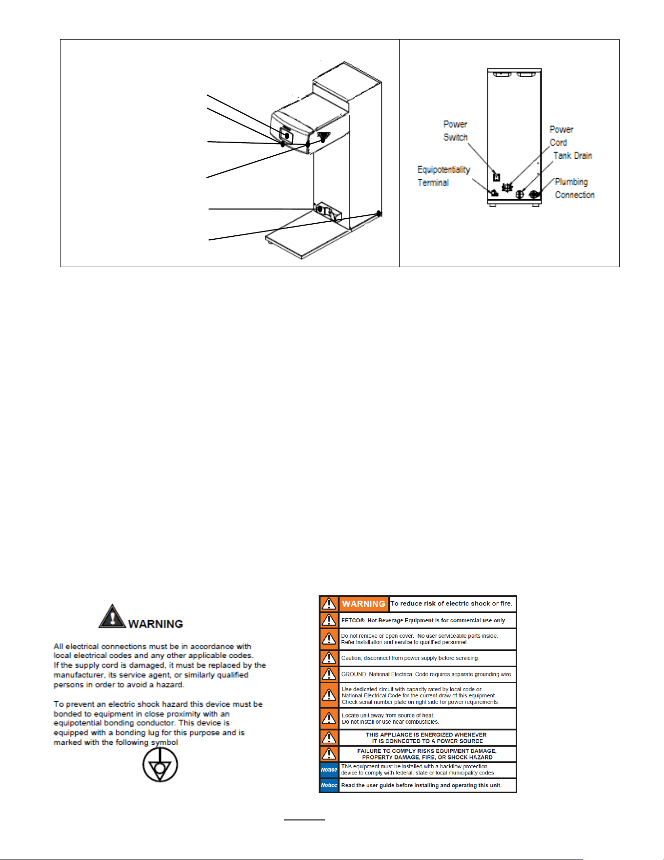
2. Note Equipotentiality Terminal, if present,
(To identify the terminals which, when connected together, bring the various parts of
equipment or of a system to the same potential, not necessarily being the earth (ground) potential, e.g. for local bonding.)
3. Verify voltages, polarity, circuits, and circuit breaker access before attaching equipment.
4. Brewers in this series wire differently in regards to a neutral wire. Review the wire diagrams.
5. The electrical diagram is located in the User’s Guide and online at www.fetco.com.
6. Make sure of the tight grounding of the equipment and use the external ground bolt.
7. The installation must comply with applicable federal, state, and local codes having jurisdiction at your location. Check
with your local inspectors to determine what codes will apply.
See wiring diagrams for connections
Plumbing:
1. North America: All installations must comply with applicable federal, state, or local plumbing codes.
2. All Others: The water and waste piping and connections shall comply with the International Plumbing Code 2003,
International Code Council (ICC), or to the Uniform Plumbing Code 2003 (IAPMO).
3. Use an inline water filter for all beverage equipment.
4. Install the filter unit after a water shutoff valve and in a position to facilitate filter replacement.
5. The water line and newly installed filter cartage must be flushed thoroughly prior to connecting it to the brewer to
prevent debris from contaminating the machine.
6. Verify that the water line will provide a flow rate of at least 1½gpm/(5.7lpm) per minute and the water pressure is
between 20-75 psig (138-517kPa) before making any connections.
7. Use a wrench on the factory fitting when connecting the incoming water line. This will reduce stress on the internal
connections and reduce the possibility of leaks developing after the install has been completed
8. Install a backflow prevention device. Most municipalities require a recognized backflow preventer.
Usable on all hot beverage and cold beverage equipment is a WATTS® SD-2 or SD-3.
WATTS spring loaded double check valve models are accepted by most zoning authorities.
The check valve should be as close to the water supply inlet of the beverage equipment as possible.
Tank Drain
The water tank must be drained before maintenance procedures, and when the unit is to be relocated or shipped
1. Disconnect power to unit.
2. Move the unit near a sink or obtain a container large enough to hold four gallons of water and a hose clamp.
Note that the tank may hold more than four gallons and that the drain line will be clamped to empty the container.
3. NOTE: Multiple buckets may be needed during the draining, see tank volumes below
4. Remove the tank cover and allow the tank to cool to a safe temperature
5. The tank drain is located on the back of the unit. Turn the drain plug one-quarter turn in either direction
6. Pull the plug out far enough to expose the silicone tube
7. Using pliers loosen the hose clamp and move it back over the tube.
8. Crimp the tube an inch or two away from the drain plug to prevent water from flowing.
9. Use the other hand to pull the drain plug out of the tube.
10. Release the crimped tube and allow the water to flow into the sink or container.
Brewer
Hot Water Tank
Capacity
TBS-2111XTS
11.9 liter
3.1 gallon
Go to fetco.com for the latest versions of all information Page 17 User Guide & Operator instructions P152 rev.003 August 2021
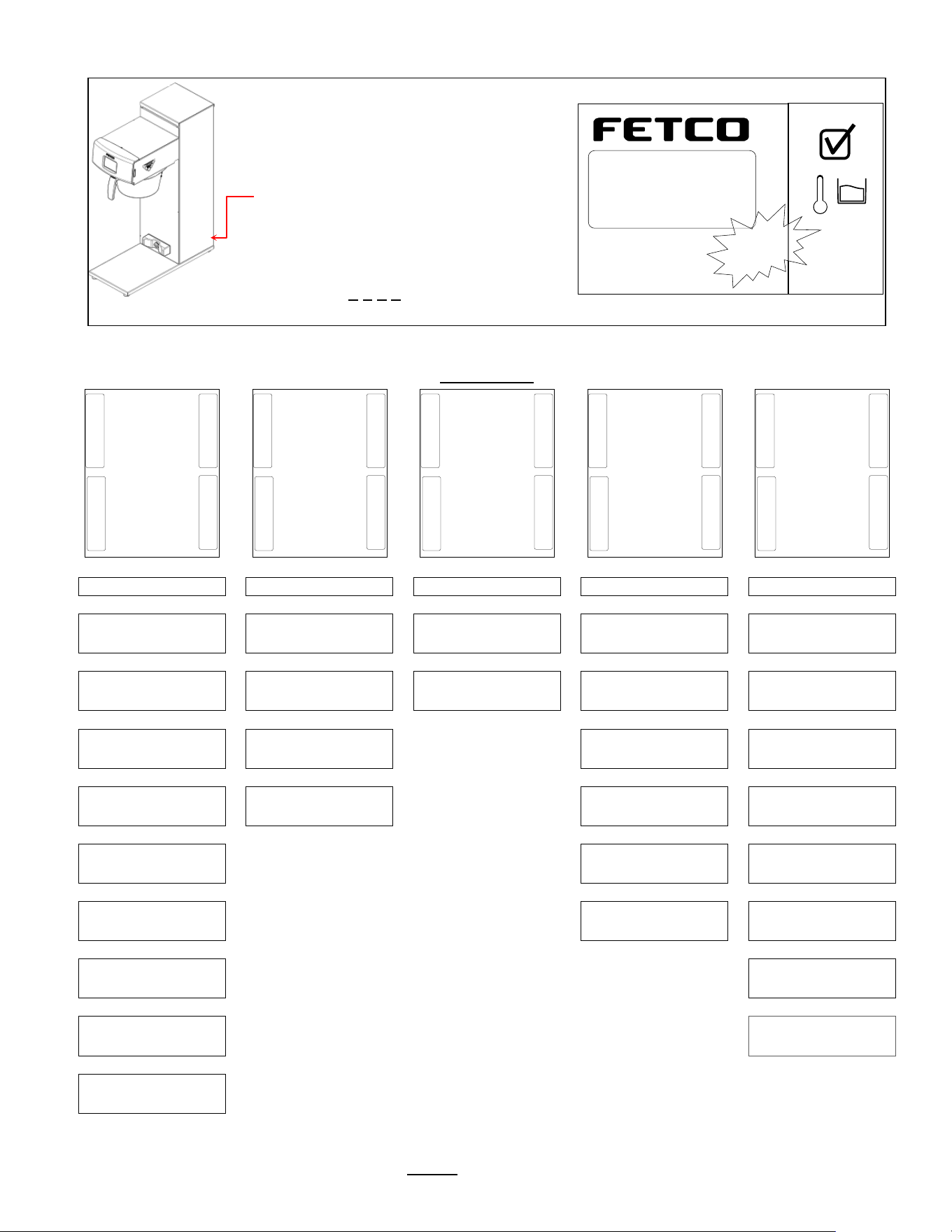
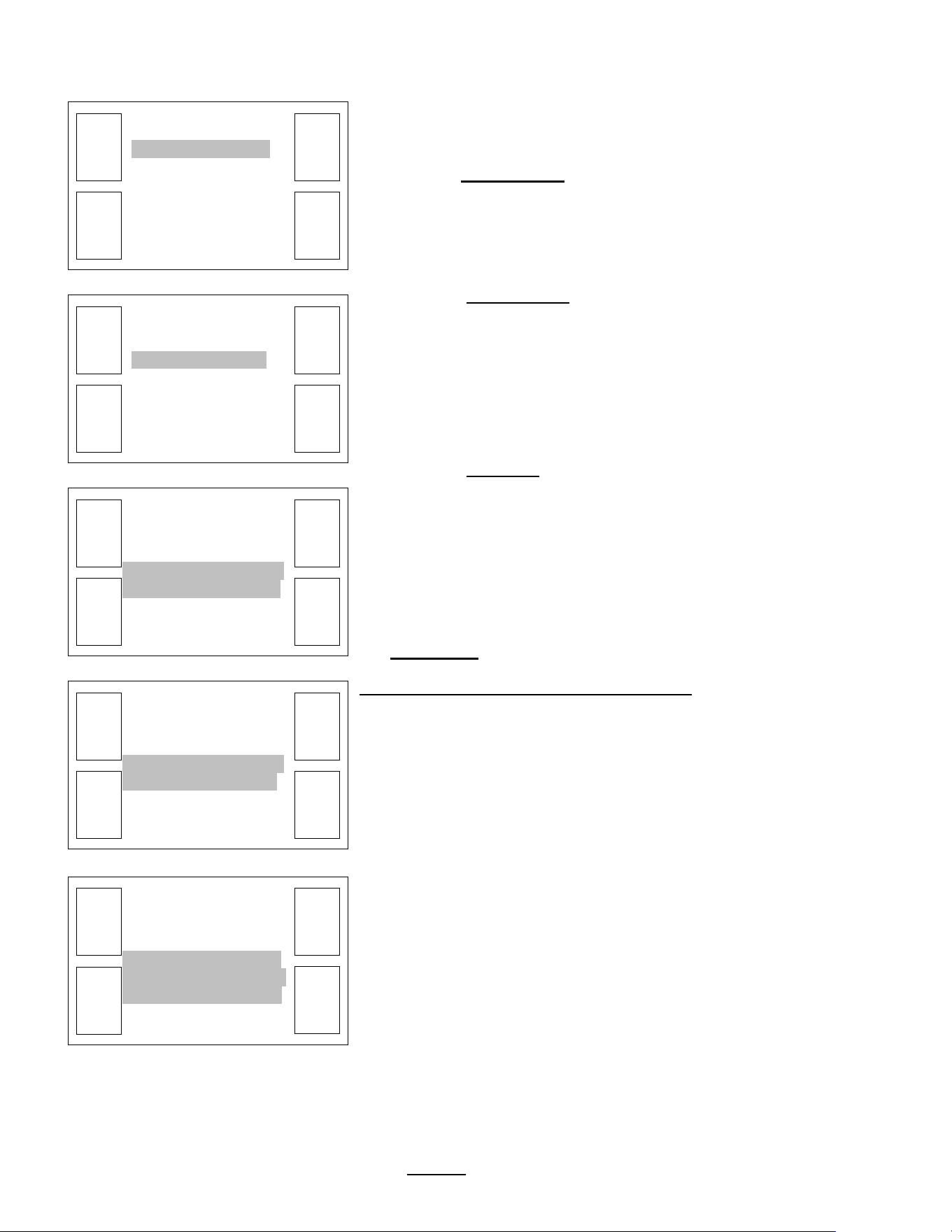
Layout of the brewer
Operation and service
Operation
Service
Layout for installing brewer
Touch-screen
(for brewer operation)
Brew basket sensor
(internal)
SD card interface port
(Load & Save)
Hot Water Faucet
(Right OR Left option)
Airpot or Dispenser Locator
Main power switch
Installation safety and hygiene directions
1. Access to the service area is restricted to persons having safety/hygiene knowledge and practical experience of the coffee
brewer. This appliance must be installed in locations where it can be overseen by trained personnel.
2. For proper operation, this appliance must be installed indoors where the temperature is between 10°C/50°F to 35°C/95°F.
Drain and remove all liquid from equipment and lines if exposed to freezing temperatures.
3. All commercial cooking equipment, including this unit, is not intended for use by children or persons with reduced physical,
sensory, or mental capabilities. Ensure proper supervision of children and keep them away from the unit.
4. Children should be supervised to ensure that they do not play hot beverage equipment.
5. This unit must be installed and serviced by qualified personnel only.
6. Installation must conform to all local electrical and plumbing codes. Installation by unqualified personnel will void the unit
warranty and may lead to electric shock or burn, as well as damage to unit and/or its surroundings.
7. If the power cord requires repair or replacement-it must be performed by the manufacturer or authorized service personnel
with the specified cord only from the manufacturer in order to avoid a hazard.
8. Review the dimensions for the unit and verify that it will fit properly in the space intended for it. Verify that the counter or
table will support the total weight of the brewer and dispensers when filled (See: Technical Data).
9. Place the brewer on the counter or stand. When the brewer is in position, level it front to back as well as side-to-side by
adjusting the legs.
10. Brewers will need a sturdy supported surface for operation. Do not move brewers when filled.
11. Do not tilt appliance more than 10° to insure safe operation.
12. Unit is for protected indoor use only. Do not steam clean or use excessive water on unit.
13. This unit is not “jet-proof” construction. Do not pressure wash or use jet spray to clean this unit.
14. The unit is not waterproof-do not submerge or saturate with water.
Equipment exposed to flood and contaminated must not be used due to electrical and food safety.
Do not operate if unit has been submerged or saturated with water.
Labels and
warnings for hot
beverage
equipment
For BACK PANEL
of equipment
1046.00035.00
Go to fetco.com for the latest versions of all information Page 18 User Guide & Operator instructions P152 rev.003 August 2021
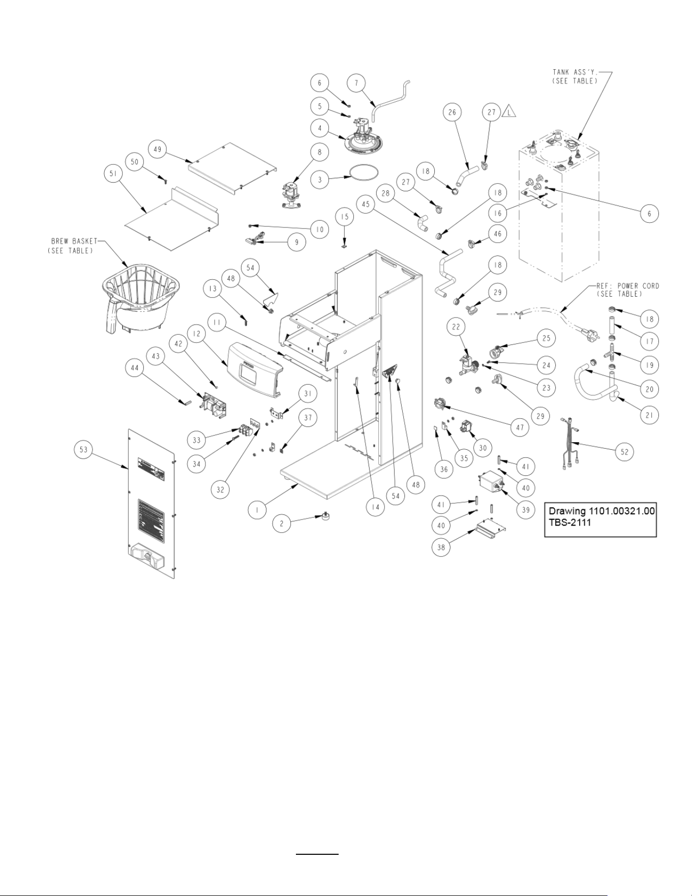
Parts Drawings and Wiring Diagrams

Go to fetco.com for the latest versions of all information Page 19 User Guide & Operator instructions P152 rev.003 August 2021
Ref#
Qty
Part number
Description Drawing 1101.00321.00 ASSEMBLY, 3kW/240VAC, TBS-2111
1
1
1111.00093.00
WELDMENT, TBS-2111
2
4
1073.00021.00
FOOT, RUBBER, 1/4-20
3
1
1024.00063.00 O-
RING, 3 15/16" x 3/32" CS, DASH # 154, BUNA-N, DURO-A50
4
1
1102.00203.00
ASSEMBLY, SPRAY HOUSING, DSVP11 DESIGN
5
6
1083.00010.00
WASHER, #10 SCREW W/NEOPRENE-BONDED SEAL
6
14
1084.00006.00
NUT, 8-32 18-8 HEX MACHINE SCREW
7
1
1025.00012.00
TUBE, 5/16"OD X 3/16"ID X 11.00"LG
8
1
1102.00390.00
ASSEMBLY, BYPASS VALVE, RIGHT
9
1
1102.00113.00
SWITCH, REED, ASSEMBLY
10
2
11029.00006.00
NUT, FINGER KNURLED, #4-40
11
1
11024.00059.00
GASKET, FRONT 4A
12
1
1102.00413.00
ASSEMBLY, FRONT PANEL TBS-2111
13
4
1082.00058.00
SCREW, # 8-32 X 5/8, FLAT HD, PH, 18-8 SS
14
1
1024.00040.00
CARD PLUG, HWD-2100
15
12
1084.00011.00
NUT, CLIP ON (J-NUT), #6-32, 22-20 GA., BLK-PH FINISH
16
6
1083.00011.00
WASHER, #8 SCREW SIZE, INTERNAL TOOTH LOCK
17
1
1025.00119.00
TUBE, 5/8"OD x 3/8"ID x 2.50"LG.
18
9
1086.00003.00
UNICLAMP, 15.9 HOSE OD CLAMP
19
1
1029.00002.00
FITTING, HOSE BARB TEE, SIZE 3/8"
20
1
1025.00114.00
DRAIN TUBE, 5/8"OD x 3/8"ID x 12"LG., CBS-2121
21
1
1025.00004.00
TUBE, 5/8"OD X 3/8"ID X 8"LG, TANK WATER INLET
22
1
1057.00043.00
SOLENOID VALVE, 5.5L/min, 180 DEG, 24VDC
23
2
1083.00005.00
WASHER, M4 18-8 SS, INT. TOOTH LOCKWASHER
24
2
1082.00010.00
SCREW, PAN HD. PHIL. MACH., M4x10 ZINC-PLATED
25
1
1102.00243.00
ADAPTER ASSY, 3/4" BSP x 1/4" NPT x 3/8" TUBE
26
1
1025.00046.00
TUBE, 5/8" OD X 3/8" ID X 5.0" LG, DOUBLE VALVE
27
2
1086.00002.00
CLAMP, HOSE, SIZE "G" NYLON
28
1
1025.00011.00
TUBE, 5/8 OD x 3/8 ID x 4.25" LG
29
2
1023.00147.00
PLUG, TANK SERVICE DRAIN FOR 18 GA AND UP BODY
30
1
1058.00024.00
SWITCH, POWER, DOUBLE POLE, 16A, 125/250 VAC
31
1
1112.00246.00
WELDMENT BRACKET TERMINAL BLOCK, 3 POLE
32
1
1052.00025.00
PLATE, MARKING #BS1016E
33
1
1052.00022.00
EUROSTRIP HE10 TERM. BLOCK, 3 POLE, 50AMP, 18-8 AWG
34
2
1082.00082.00
SCREW, PHILLIP HD., 8-32 THREAD
35
2
1065.00009.00
GROUND LUG CONNECTOR, 14-2 AWG, ALUMINUM
36
1
1044.00013.00
LABEL EQUIPOTENTIALITY, CE
37
1
1044.00012.00
LABEL GROUND, CE
38
1
1112.00528.00
WELDMENT, TBS-2111 BRKT EMI FILTER
39
1
1052.00029.00
EMI FILTER, TWO LINE 20A, 120/250VAC
40
1
1083.00009.00
WASHER, #6 SCREW , INTL TOOTH LOCKWASHER
41
4
1081.00061.00
STANDOFF, 1/4 HEX x 1 1/4 LG., #6-32 THREAD
42
4
1081.00006.00
SPACER, 6MM OD x 3.2MM ID x 5MM LG, Z/P
43
1
1052.00001.00
POWER SUPPLY, 90-264VAC/24VDC, 1.8A
44
4
1029.00012.00
SPACER, .25" HEX X 1" LG, FEM #4-40 THREAD
45
1
1025.00120.00
TUBE, 9/16"OD X 5/16"ID X 13.00"LG
46
1
1086.00001.00
CLAMP, HOSE, .590" - .673" DIA RANGE
47
1
1086.00008.00
CONNECTOR, CLAMP, NON-METALLIC CABLE, 3/4"
48
2
1086.00047.00
CAP PLUG, PANEL, 15/32 ID x 5/8 OD, TBS-2111
49
1
1001.00338.00
COVER, TOP, TBS-2111
50
13
1082.00017.00
SCREW, TRUSS HD. PHIL. MACHINE, # 6-32 X 1/2 LG.
51
1
1001.00337.00
COVER, UPPER BASE, TBS-2111
52
1
1402.00093.00
HARNESS, UNIVERSAL, TBS-2111
53
1
1102.00344.00
ASSEMBLY, FRONT COVER, TBS-2111
54
2
1046.00006.00
LABEL, WARNING, "HOT WATER FAUCET"
Ref.
1
B020000G2
BREW BASKET ASS'Y., TBS-2111, GREEN HANDLE PLUG-STANDARD
Ref.
1
B022000G1
Stainless Steel Brew Basket TBS-2111 16" X 6", Green Handle-OPTIONAL
Ref.
1
1063.00030.00
CORD PWR, 16A/250VAC, EU1-16P PLUG, W/O
Ref.
1
1063.00011.01
POWER CORD, AUSTRALIAN 15A 250V, 2.5M LG. W/O TERMINALS
Ref.
1
1063.00016.00
POWER CORD, DOMESTIC 120VAC W/NEMA 5-15P PLUG
Ref.
1
1104.00143.00
HOT WATER TANK ASSEMBLY, TBS-2111 3kW/240VAC -
Ref.
1
1104.00143.01
HOT WATER TANK ASSEMBLY, TBS-2111 2.3kW/240VAC -
Ref.
1
1104.00209.00
HOT WATER TANK ASSEMBLY, TBS-2111 1.7kW/120VAC -
Go to fetco.com for the latest versions of all information Page 20 User Guide & Operator instructions P152 rev.003 August 2021
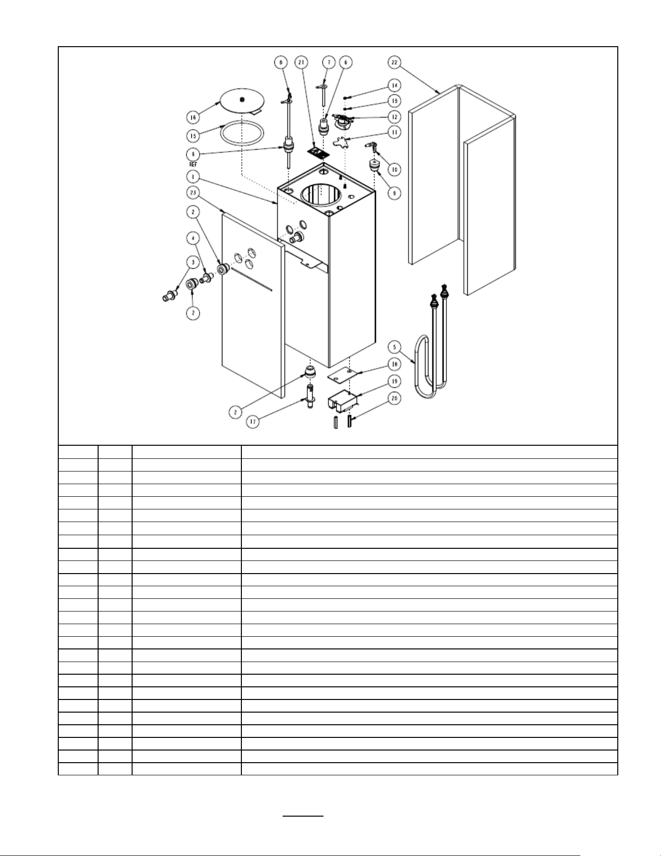
Drawing 1104.00143.00 TANK ASSEMBLY, 3kW/240VAC, TBS-2111
Ref#
Qty
Part number
Description
1
1
1114.00145.00
WELDMENT, TANK, TBS-2111
2
4
1024.00050.00
GROMMET, SILICONE, 11.4mm ID
3
2
1023.00167.00
FITTING, BREW, GROMMET DESIGN
4
1
1023.00168.00
FITTING, HOT WATER, GROMMET DESIGN
5
1
1107.00018.00
HEATER ASSEMBLY, IMMERSION 3000W/240VAC
5
1
1107.00020.00
HEATER ASSEMBLY, IMMERSION 2300W/240VAC
5
1
1107.00022.00
HEATER ASSEMBLY, IMMERSION 1700W/120VAC
6
2
1024.00053.00
LEVEL AND TEMP PROBE GROMMET
7
1
1112.00002.00
PROBE WELDMENT, WATER LEVEL 2.25" LG
8
1
1102.00161.00
PROBE ASSEMBLY, TEMP. AND LLC, HWD-2100
9
1
1024.00062.00
GROMMET, SHORT, SILICONE, LEVEL AND TEMP PROBE
10
1
1029.00023.00
FITTING, SINGLE BARBED ELBOW, 1/4", KYNAR
11
1
1003.00005.00
BRACKET, ONE SHOT THERMOSTAT
12
1
1053.00004.00
THERMOSTAT, SINGLE SHOT, 25A
13
2
1083.00009.00
WASHER, #6 SCREW , INTL TOOTH LOCKWASHER
14
2
1084.00010.00
NUT, HEX, #6-32, UNDERSIZED, ZINC PLATED
15
1
1024.00007.00
O-RING, DASH #344, TANK COVER
16
1
1102.00007.00
TANK COVER ASSEMBLY
17
1
1023.00166.00
FITTING, COLD WATER INLET, GROMMET DESIGN
18
1
1003.00140.00
ALUMINUM BRACKET FOR SSR
19
1
1052.00033.00
RELAY, SOLID STATE, 50A/480VAC, W/BUILD IN VARISTOR
20
2
1081.00042.00
STANDOFF, 1/4" HEX
21
1
1044.00004.00
LABEL, DANGER, HIGH VOLTAGE
22
1
1022.00101.00
BACK INSULATION, TANK, TBS-2111
23
1
1022.00102.00
FRONT INSULATION, TANK, TBS-2111
Go to fetco.com for the latest versions of all information Page 21 User Guide & Operator instructions P152 rev.003 August 2021
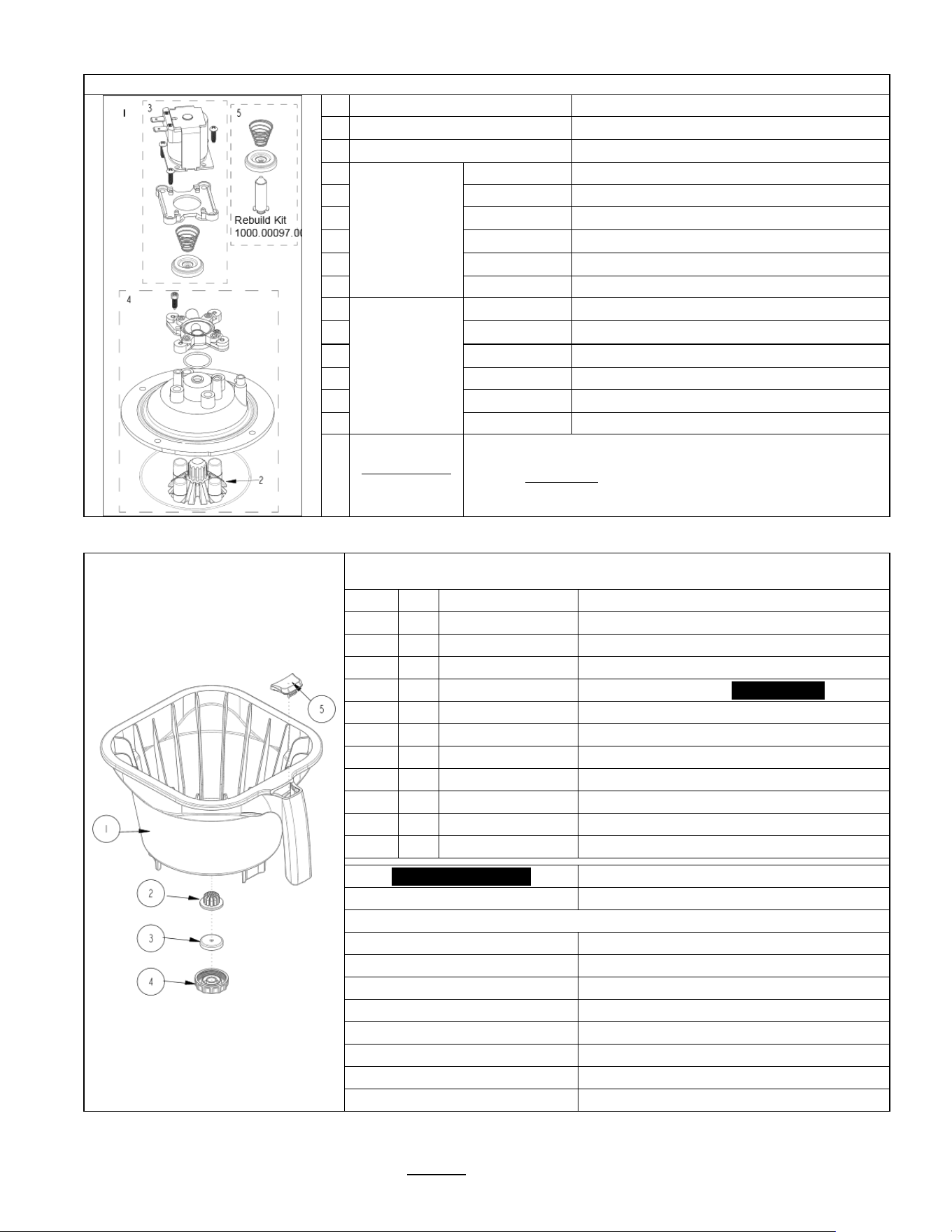
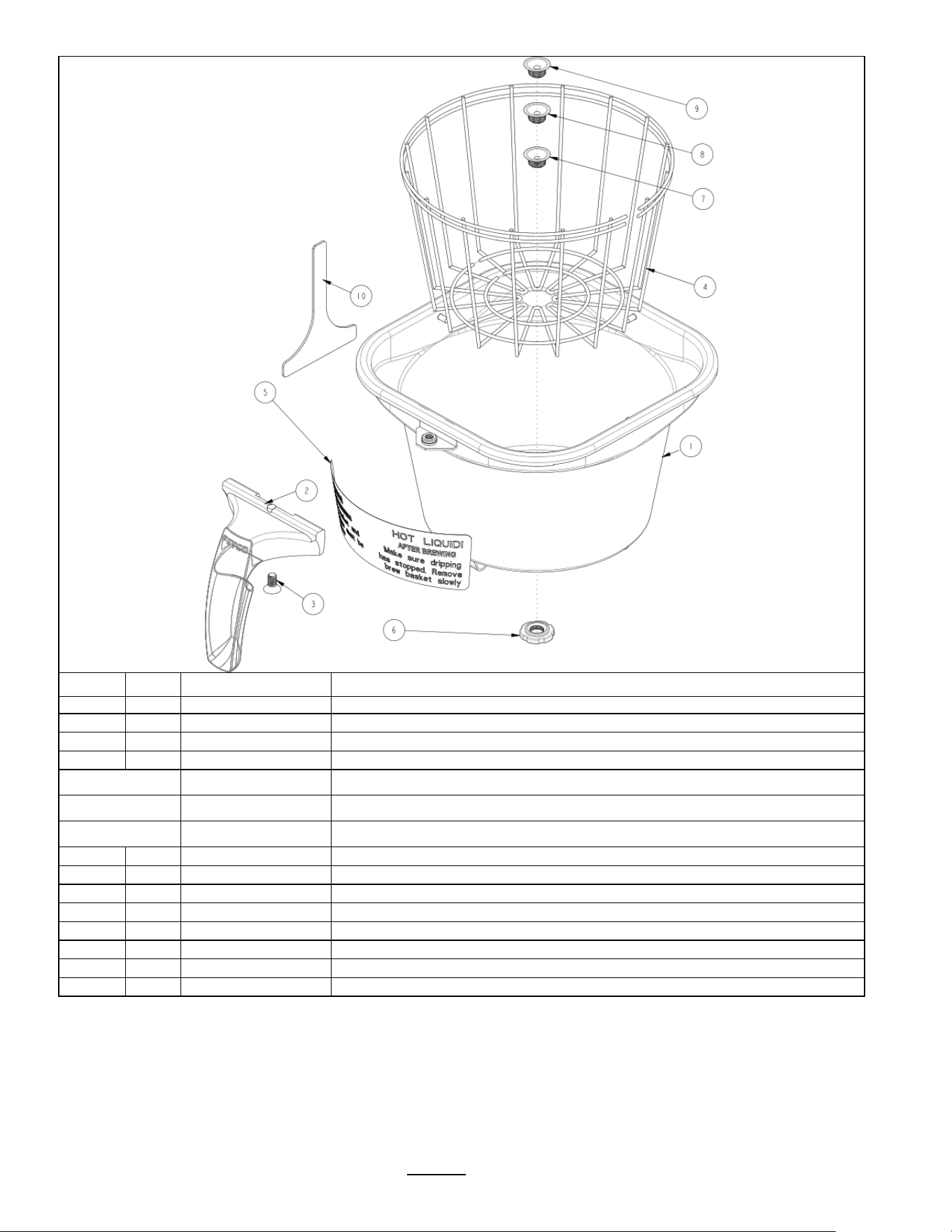
1102.00203.00
Spray Housing Assembly Parts
TBS-2111XTS
Ref.
PART NO
DESCRIPTION
1
1102.00203.00
Complete Spray Housing
2
1102.00019.00
Replacement, Cascade Spray Dome
3
#3 Contained in
KIT
1000.00097.00
1057.00038.00
VALVE DIAPHRAGM
3
1057.00252.00
ADAPTER PLATE, SPACER
3
1057.00040.00
PLUNGER, DISPENSE VALVE 24VDC
3
1057.00051.00
SPRING, DISPENSE VALVE 24VDC
3
1057.00022.00
COIL AND FRAME ASSEMBLY DSV11 24VDC
3
1082.00076.00
SCREW, #6-20 X 1/2", PHIL
4
#4 Contained in
KIT
1000.00096.00
1102.00020.00
SPRAY HOUSING ASSY CSD DESIGN
4
O-RING, AS568A-019, BUNA-N
4
1102.00019.00
ASSEMBLY, CASCADE SPRAY DOME
4
1023.00189.00
ADAPTER, SPRAY HSG, DSV11 VALVE
4
1082.00068.00
SCREW, M3.9x13, CHEESE PH
4
1024.00063.00
O-RING,Lower 3 15/16" x 3/32"
5
Valve rebuild kit
1000.00098.00
Kit contains: SPRING DIAPHRAGM PLUNGER
.
TBS-2111XTS Plastic Brew Basket
Ref#
Qty
Part Number
Description
B020000G2
Complete TBS-2111XTS Brew basket
1
1
1023.00289.00
BREW BASKET, 16" X 6", TBS-2111,
2
1
1024.00060.00
STRAINER, SILICONE
3
1
1023.00185.00
ORIFICE, SET OF 9 SEE BELOW
4
1
1023.00179.00
NUT, BREW BASKET ORIFICE HOLDER
5
1
1023.00191.00
PLUG, BB HANDLE, GREEN (Included)
5
1
1023.00190.00
PLUG, BB HANDLE, RED (Optional)
5
1
1023.00180.00
PLUG, BB HANDLE, BLUE (Optional)
5
1
1023.00192.00
PLUG, BB HANDLE, ORANGE (Optional)
5
1
1023.00194.00
PLUG, BB HANDLE, BLACK (Optional)
5
1
1023.00195.00
PLUG, BB HANDLE, BROWN (Optional)
* #5 orifice set size
ESTIMATED Drain time for 1 gallon hot
t
0.094
11:30 minutes: seconds
0.094 is DEFAULT-Factory installed on brew basket
0.062
24:30 minutes: seconds
0.078
17:30 minutes: seconds
0.086
15:30 minutes: seconds
0.104
10:30 minutes: seconds
0.125
8:10 minutes: seconds
0.140
6:30 minutes: seconds
0.180
3:30 minutes: seconds
0.280
1:20 minutes: seconds
Go to fetco.com for the latest versions of all information Page 22 User Guide & Operator instructions P152 rev.003 August 2021
OPTIONAL Stainless Steel Brew Basket (OPTIONAL)
Ref#
Qty
Part Number
Description
B022000G1
Complete TBS-2111 brew basket 16" X 6", GREEN HANDLE
1
1
1112.00505.00
BB WELDMENT, 16"x6", WITH FORMED HOLE, TBS-2111
2
1
1102.00066.00
HANDLE W/MAGNET ASSEMBLY, GREEN RUBBER
Optional colored
handle
1102.00065.00 HANDLE W/MAGNET ASSEMBLY, RED
Optional colored
handle
1102.00064.00 HANDLE W/MAGNET ASSEMBLY, BLACK
Optional colored
handle
1102.00067.00 HANDLE W/MAGNET ASSEMBLY, ORANGE
3
1
1082.00040.00
SCREW, FLAT HD. PHIL. W/NYLON PATCH, 1/4-20 X .50
4
1
1009.00005.00
BASKET, WIRE, 16" X 6"
5
1
1046.00025.00
LABEL, BREW BASKET WARNING, GRAY
6
1
1013.00121.00
NUT, BREW BASKET, TBS-2111
7
1
1013.00122.01
RESTRICTOR, BREW BASKET, Ø.159 HOLE, TBS-2111
8
1
1013.00122.02
RESTRICTOR, BREW BASKET, Ø.177 HOLE, TBS-2111
9
1
1013.00122.03
RESTRICTOR, BREW BASKET, Ø.196 HOLE, TBS-2111
10
1
1003.00351.00
TOOL, INSTALLATION, BB ORIFICE, TBS-2111
Go to fetco.com for the latest versions of all information Page 23 User Guide & Operator instructions P152 rev.003 August 2021
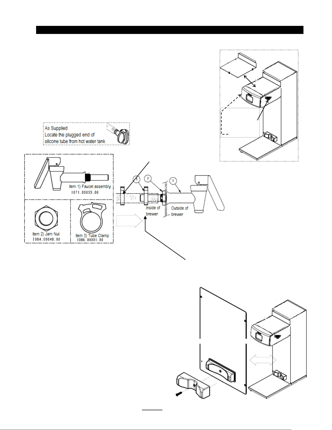
Hot water faucet installation instructions
Hot water service faucet, if required by operator, is installed before initial set-up
TBS-2111XTS is supplied with part number 1000.00109.00 hot water faucet accessory set.
Professional installation is required. Do not connect water or electrical utilities before installing.
____________________________________________________________________________________
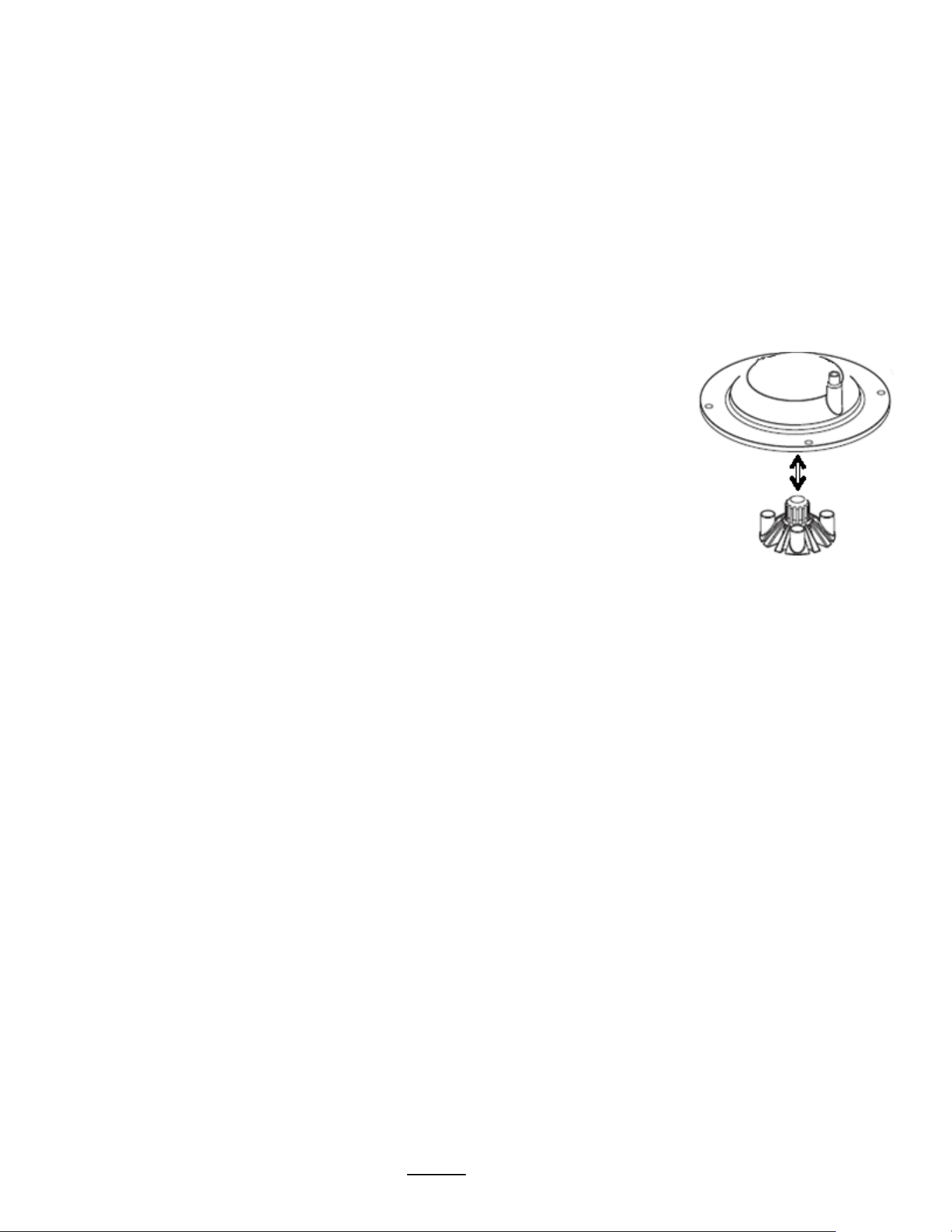
Configurable Dispenser Locator
Factory configured for 7 inch dispenser
To Configure for wider dispensers:
Remove screw and 7 inch adapter as shown
1) Remove top cover-as shown
2) Remove the 16mm/5/8” round plug from the enclosure
Select either the left or right side
-(left side shown)
3) From outside of
brewer-Install faucet assembly
4) From inside of brewer
-Thread jam nut on faucet stub.
5) Tighten jam nut firmly against enclosure wall
6) Locate plugged hot water supply silicone tube.
7) Remove plug from hot water supply silicone tube
8) Place clamp 2
-3 inches from open tube end as shown
9) Push open end of silicone tube over faucet stub
10) Slide clamp over tube and secure. Tube and clamp must be secure
11) Fill brewer and test faucet
-check for leaks and reinstall top cover
Slide clamp
to secure
Remove top cover
Remove 16mm/5/8”
round plug from left
or right side

End of section notes
N