RANGE
MODEL NUMBER SERIES
| |
INSTRUCTION MANUAL
ENGLISH
®
JKD36A1/JKD48A1
07/2024
2
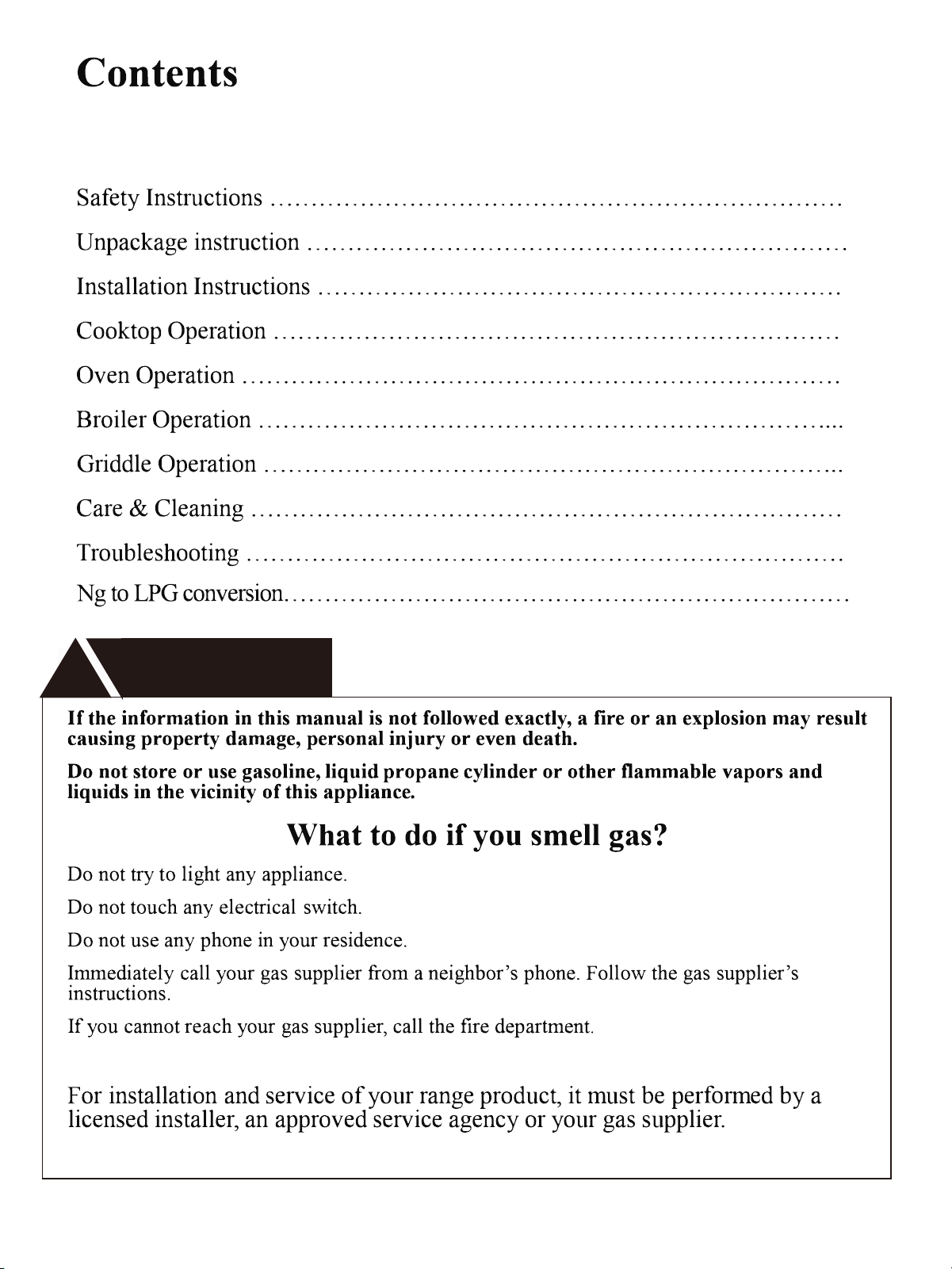
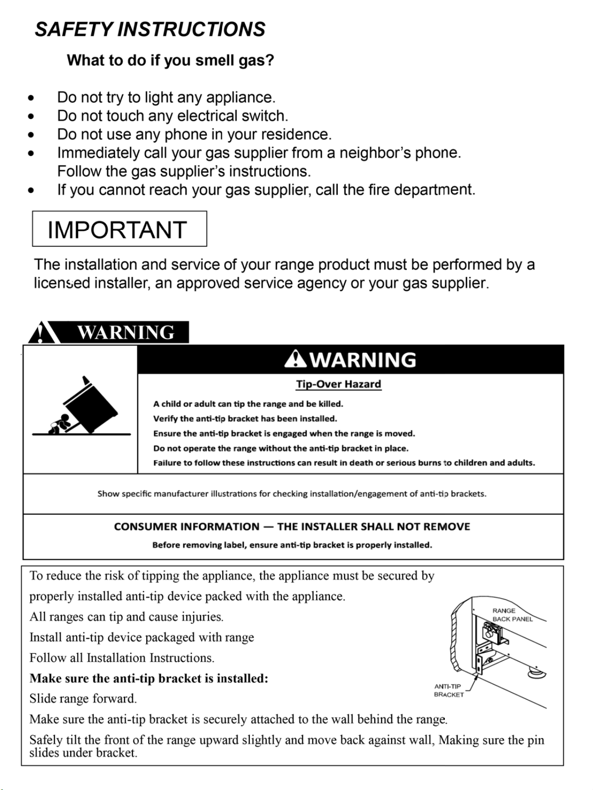
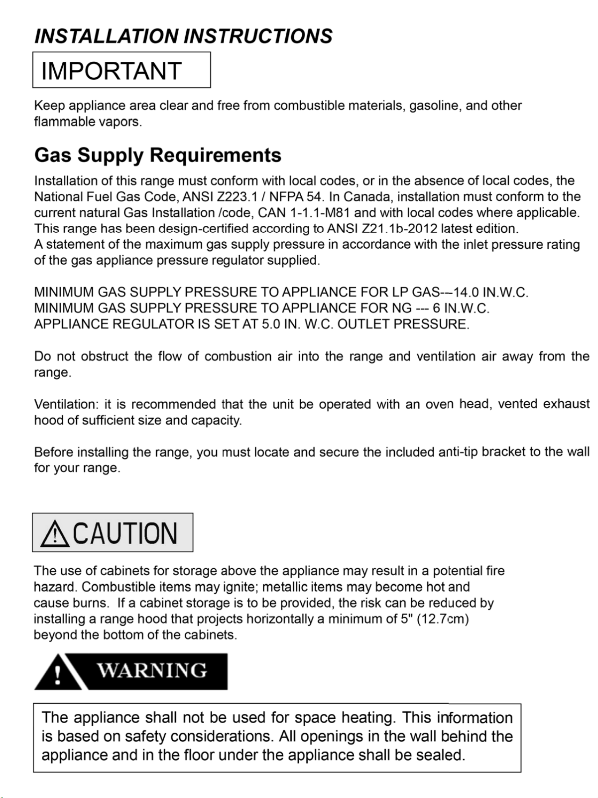
WARNING
!
Customer Care
....................................................................................... 4
5~7
8
9~18
19~21
22~23
24
25
26~27
28
29-32
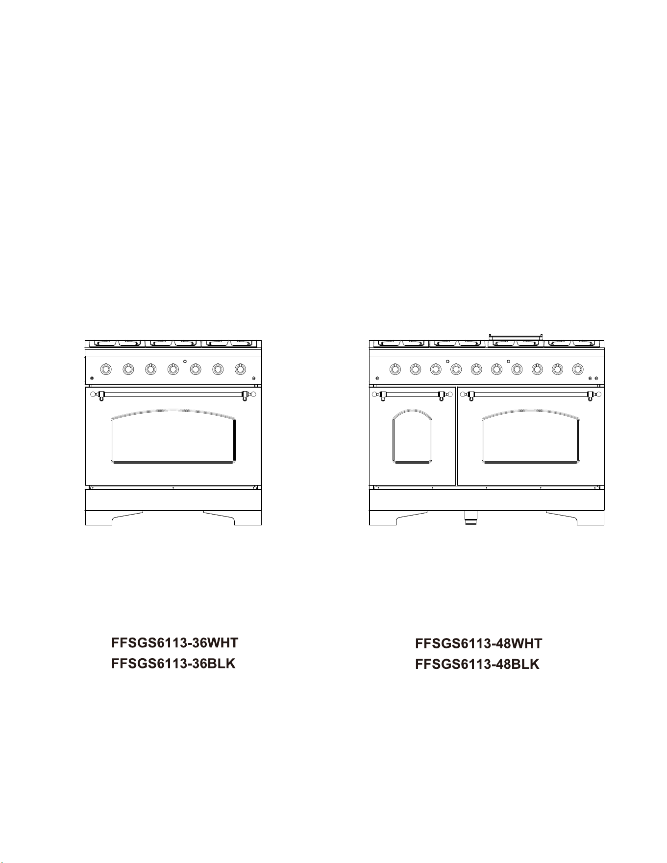
MODEL NUMBER SERIES MODEL NUMBER SERIES
DUAL FUEL RANGE
3
JKD36A1 JKD48A1
4
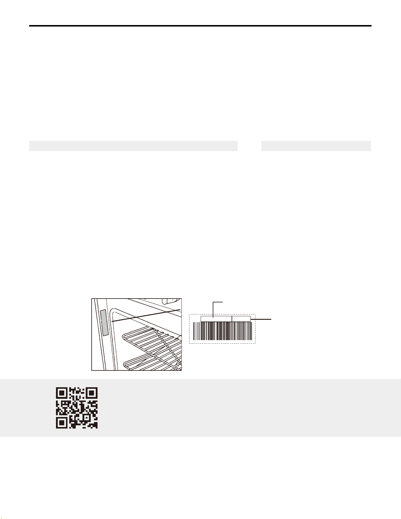
nd SeriaModel And Serial NumberA
S/N:
FFSGS6113-36WHT
XXXXXXX
Model Number
Serial Number
Thank you for purchasing a Frono product. Please read the entire instruction manual before operating your new
appliance for the first time. Whether you are an occasional user or an expert, it will be beneficial to familiarize yourself
with the safety practices, features, operation and care recommendations of your appliance.
Both the model and serial number are listed inside the product. For warranty purposes, you will also need the date of
purchase .
Services in Canada and Untied States
Keep the instruction manual handy to answer your questions. If you don’t understand something or need more
assistance, please visit our website for fast support. Please provide us your name, number, address,serial number
of the product that troubleshooting, proof of purchase, and a short description of the issue. A customer service
representative will contact you as soon as possible. All warranty work needs to be authorized by FORNO customer
service. All our authorized service providers are carefully selected and rigorously trained by us.
Product Information Service Information
Model Number : _________________________________________
Use these numbers in any
correspondence or services calls
concerning your product.
If you received a damaged product,
immediately contact Forno.
To save time and money, before
you call for serviced, check the
troubleshooting guide. It listed the
causes of minor operation problems
that you can correct yourself.
Serial Number : __________________________________________
Date of Purchase :________________________________________
Purchase Address And Phone : _____________________________
_______________________________________________________
_______________________________________________________
Customer Care
“Need some quick help? Simply scan the qr code and get access
to our fast support form. We’re always here to assist you with any
questions or concerns you may have. So, don’t hesitate to reach out!”
5
6
7
8
9
10
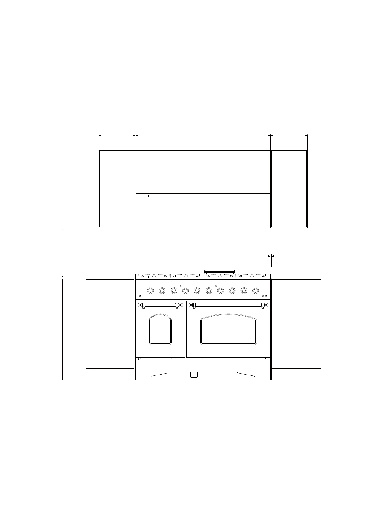
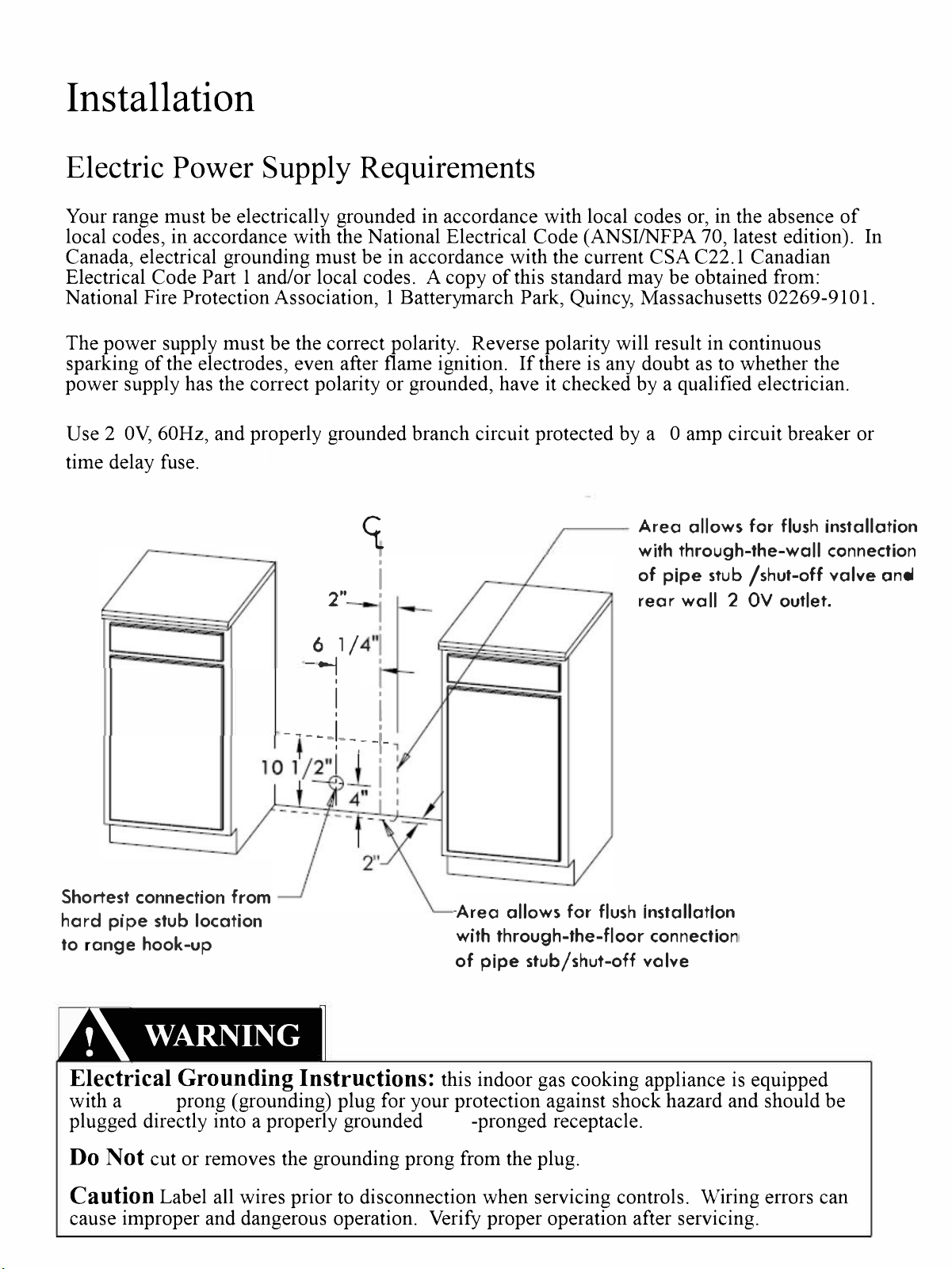
INSTALLATION INSTRUCTIONS
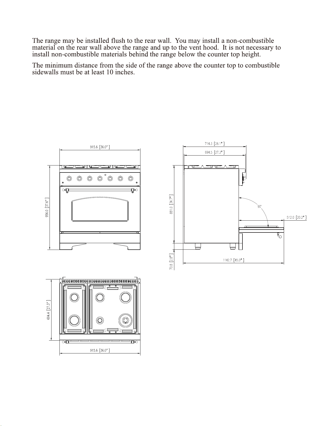
Dimensions and Clearances
INSTALLATION INSTRUCTIONS
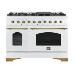
FFSGS6113-36WHT
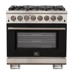
FFSGS6113-36BLK
*Product features may not match. Image meant for dimension reference only.
11
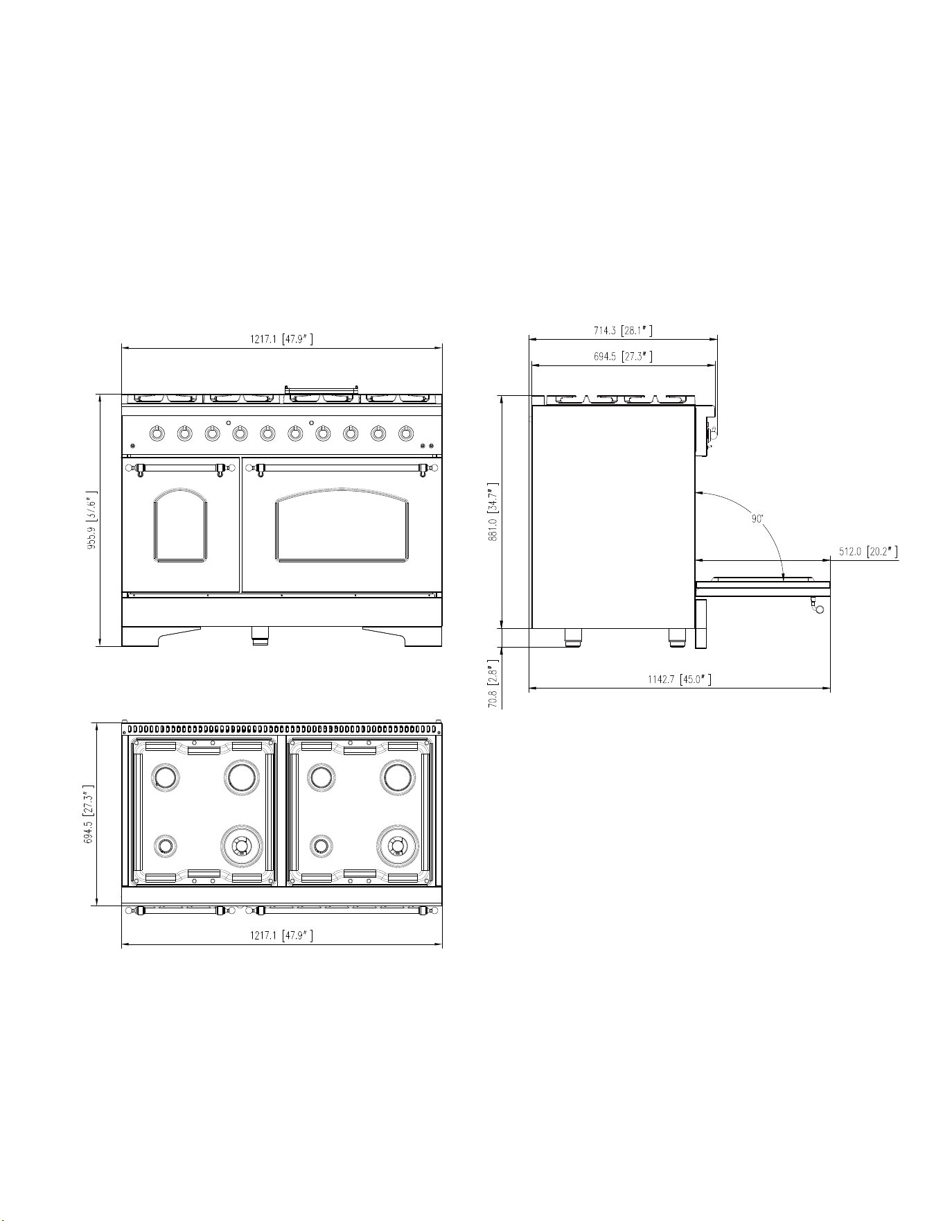
*Product features may not match. Image meant for dimension reference only.
12
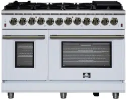
FFSGS6113-48WHT
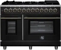
FFSGS6113-48BLK
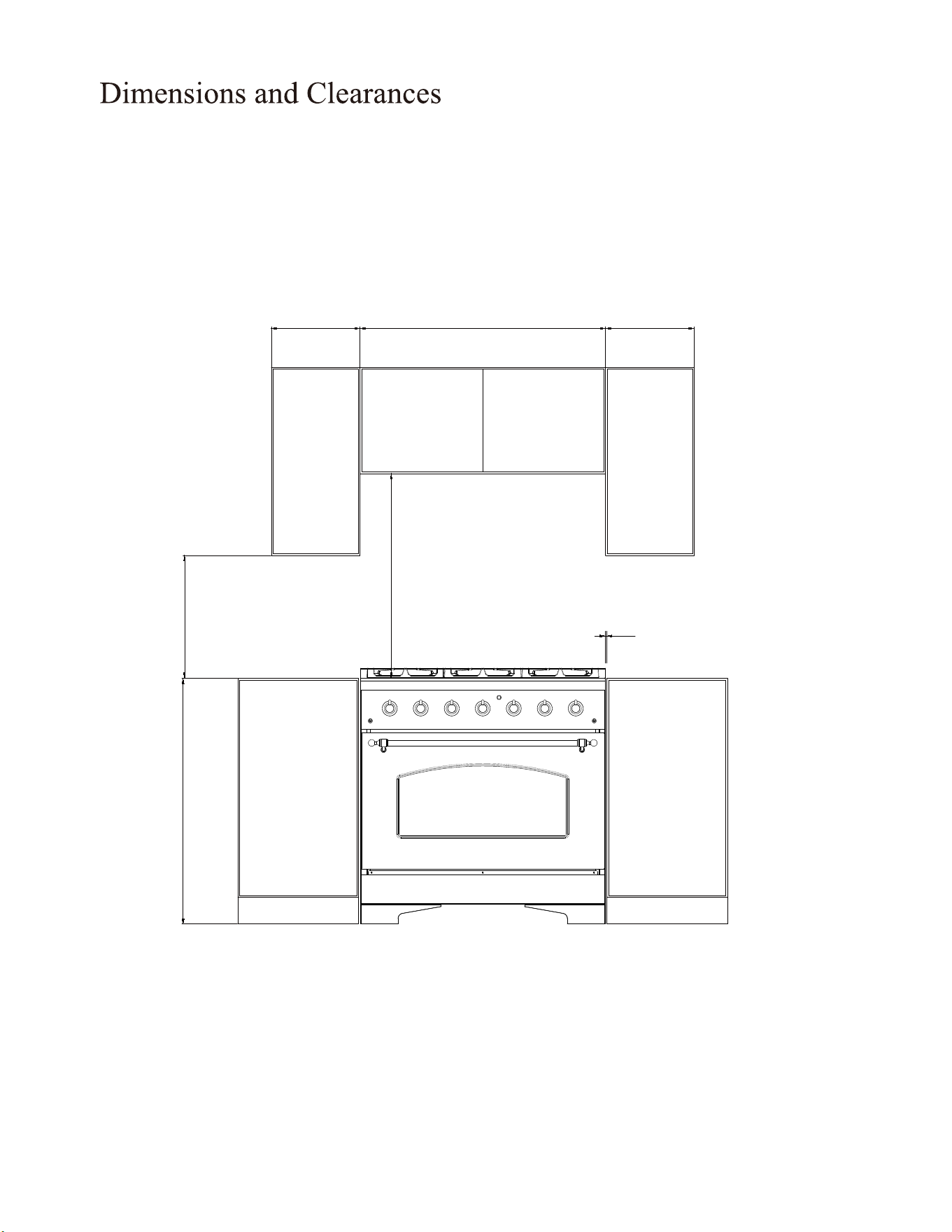
13”
18”
30”Minimum
2”To wall on either side
sealed burner models
Minium to
cabinets on
either side
of the range
36”
13”
36”
13
FFSGS6113-36WHT
FFSGS6113-36BLK
30”Minimum
To wall on either side
sealed burner models
Minium to
cabinets on
either side
of the range
2”
13”
18”
36”
13”48”
14
FFSGS6113-48WHT
FFSGS6113-48BLK
15
Installation Instructions
Before using your range
1.Remove all packaging material.
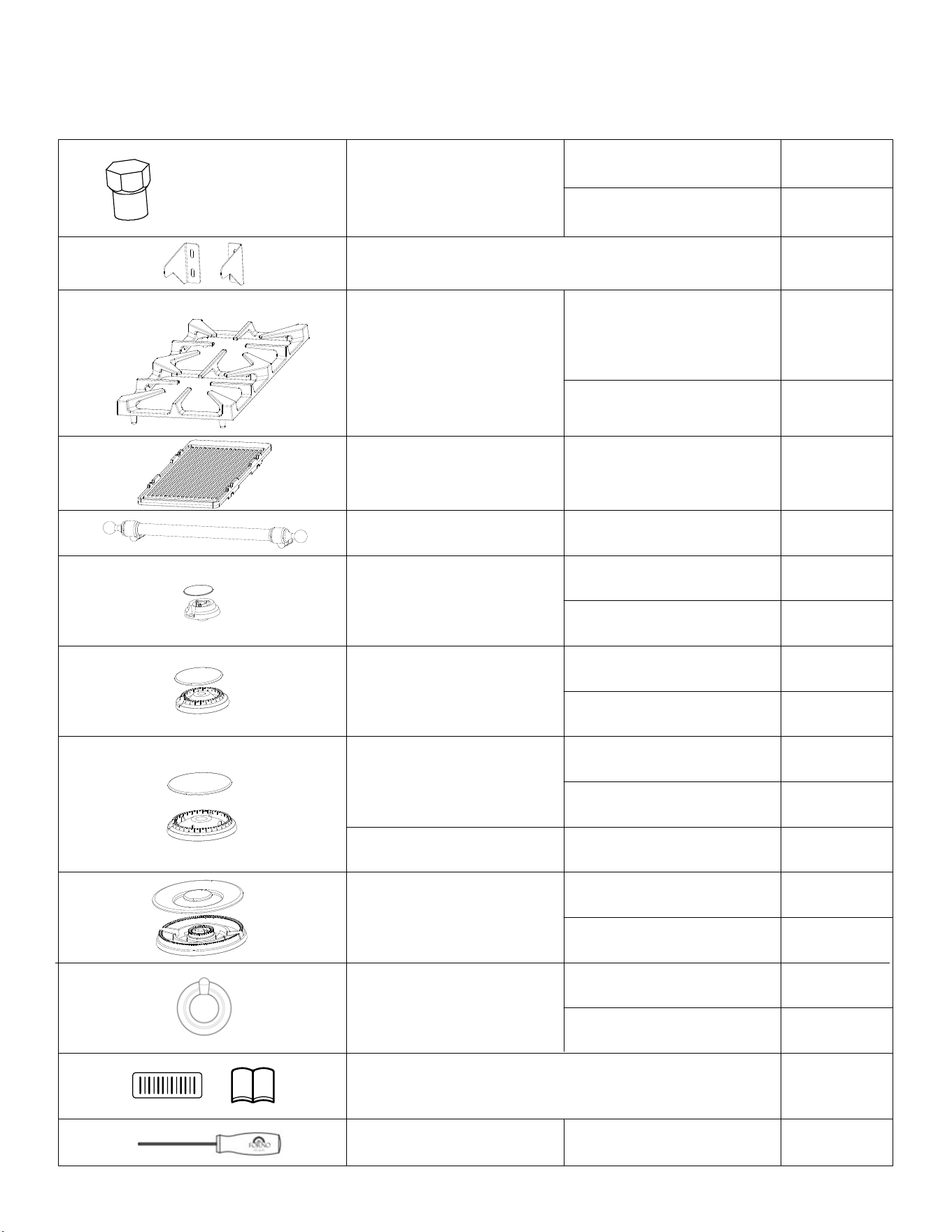
2.Check to make sure you have all of the accessories listed below
LPG injector
FFSGS6113-36
FFSGS6113-48
1 set
1 set
Anti-tip bracket and screws
Burner Grills
Cook plate(Griddle)
1 set
3 pieces
4 pieces
1 piece
1 piece
oven door handle
Burner & Cap
(9000BTU)
Burner & Cap
(6000BTU)
Burner & Cap
(15000BTU)
Burner & Cap
(12000BTU)
Burner & Cap
(20000BTU)
Knob
Serial Number Sticker & Instruction Manual
Screw Driver
10 pieces
7 pieces
1 piece
1 set
2 sets
1 set
2 sets
1 set
2 sets
1 set
FFSGS6113-36
FFSGS6113-48
FFSGS6113-48
FFSGS6113-36
FFSGS6113-36
FFSGS6113-48
FFSGS6113-36
FFSGS6113-48
FFSGS6113-36
FFSGS6113-48
1 set
FFSGS6113-36
2 sets
1 setFFSGS6113-36
FFSGS6113-48
FFSGS6113-36
FFSGS6113-36
FFSGS6113-48
FFSGS6113-36:
0.89*2+0.53,1.0,0.74,
0.90*2,1.16
FFSGS6113-48:
(0.89*2+0.53)*2,1.0*2,
0.74*2,0.90*2
4
4
4
16
17
•
•
•
•
• Install male ½” flare union adapter to ½” NPT internal thread elbow at inlet of
thread end of the ½” flare union adapter to the ½” NPT internal thread at inlet of
• Install male ½” or ¾” flare union adapter to the NPT internal thread of the manual
•
• When all connections have been made, check that all range controls are in the “off”
• Leak testing of the appliance shall be conducted according to the manufacture’s
• The appliance must be isolated from the building’s gas supply piping system by
INSTALLATION INSTRUCTIONS
four
four
four
three
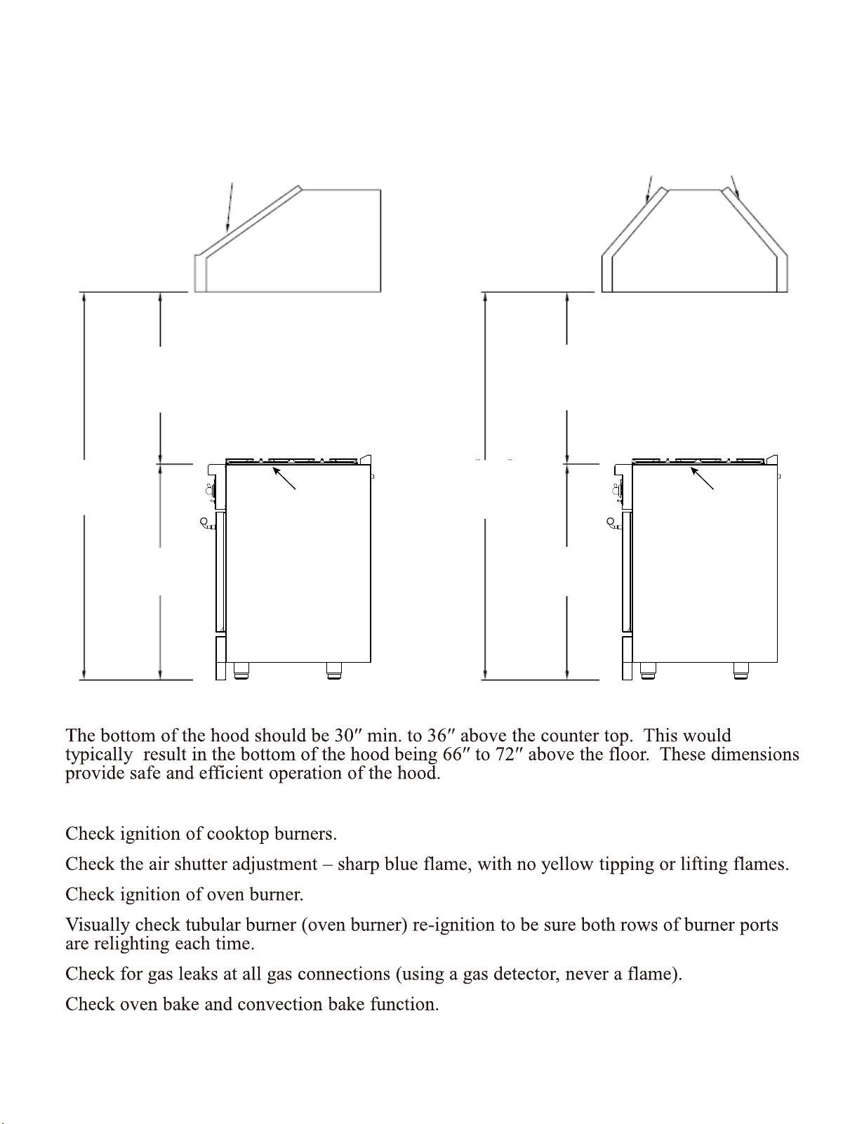
After Installation:
Hood/Composite Overlay Install
30”(762)min
36”(914)max
66”-72”
(1676-1829)
30”(762)min
36”(914)max
66”-72”
(1676-1829)
36“
914
36“
914
WALL
INSTALLATION
wood compsite overtay
ISLAND
INSTALLATION
wood compsite overtay
metal hoodmetal hood
18
countertop
countertop
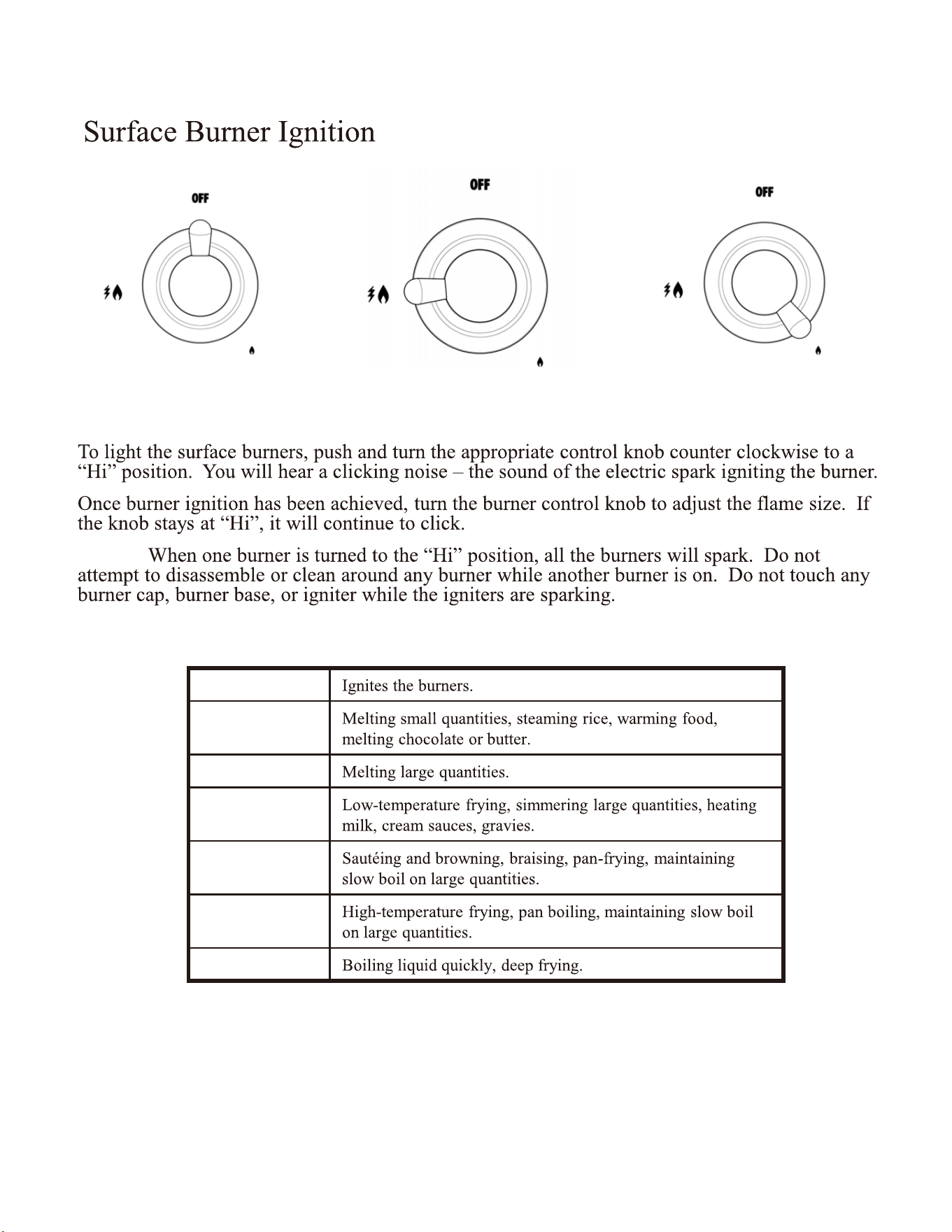
Push to release gas.
Adjust to appropriate
flame height.
Turn to Ignite and ‘Hi’ position.
NOTE:
Heat Settings:
Hi
Simmer
Low
Low-Medium
Medium
Medium – Hi
Hi
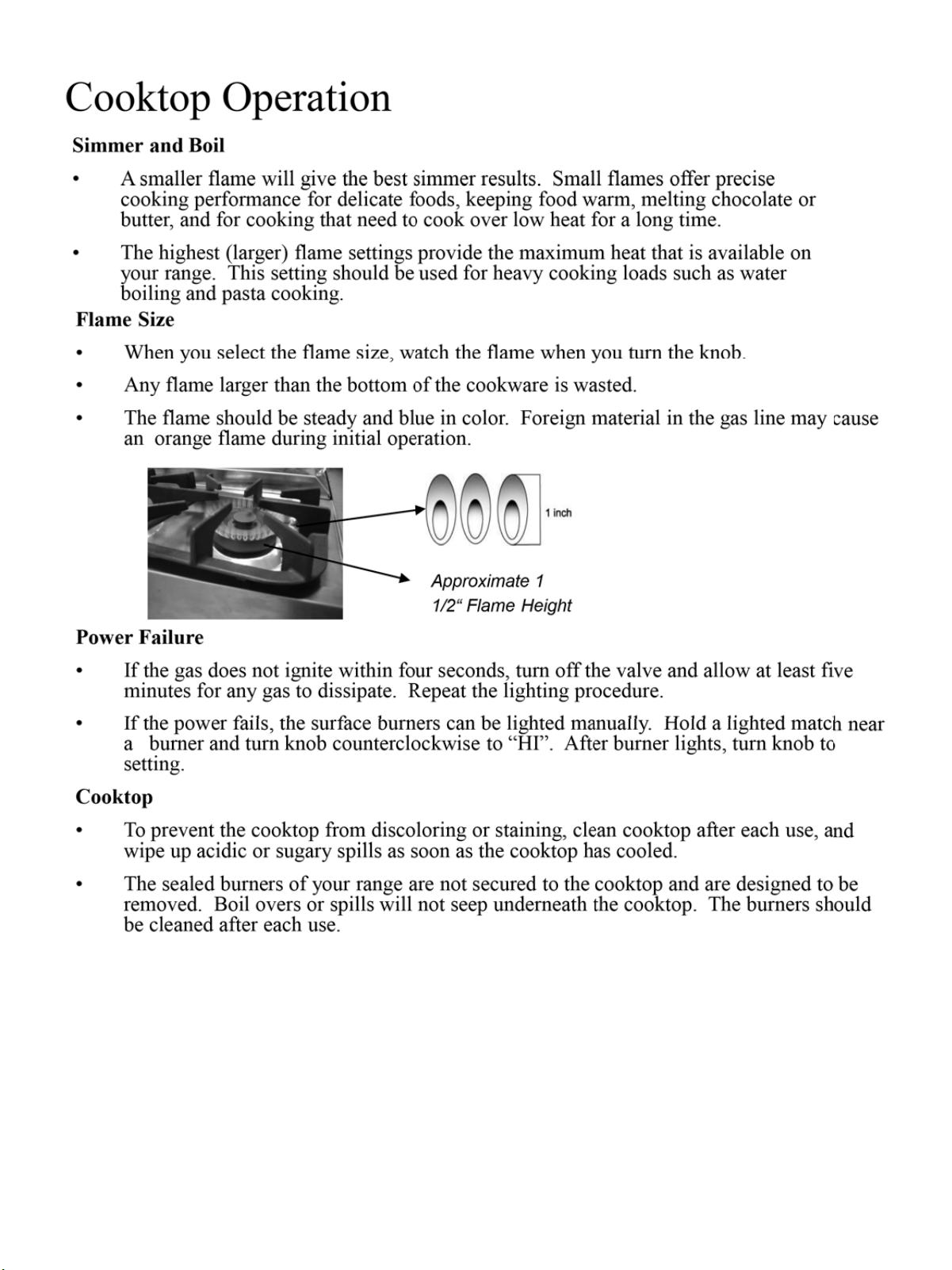
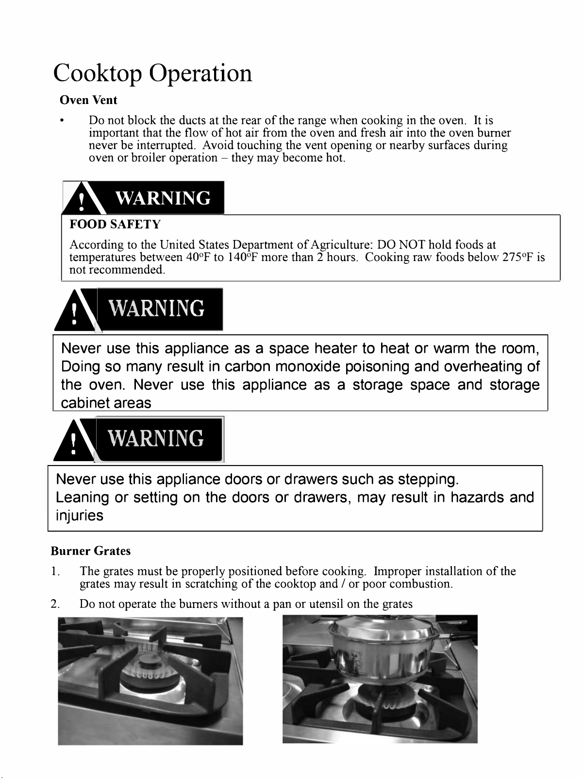
COOKTOP OPERATION
19
20
21
22
23
24
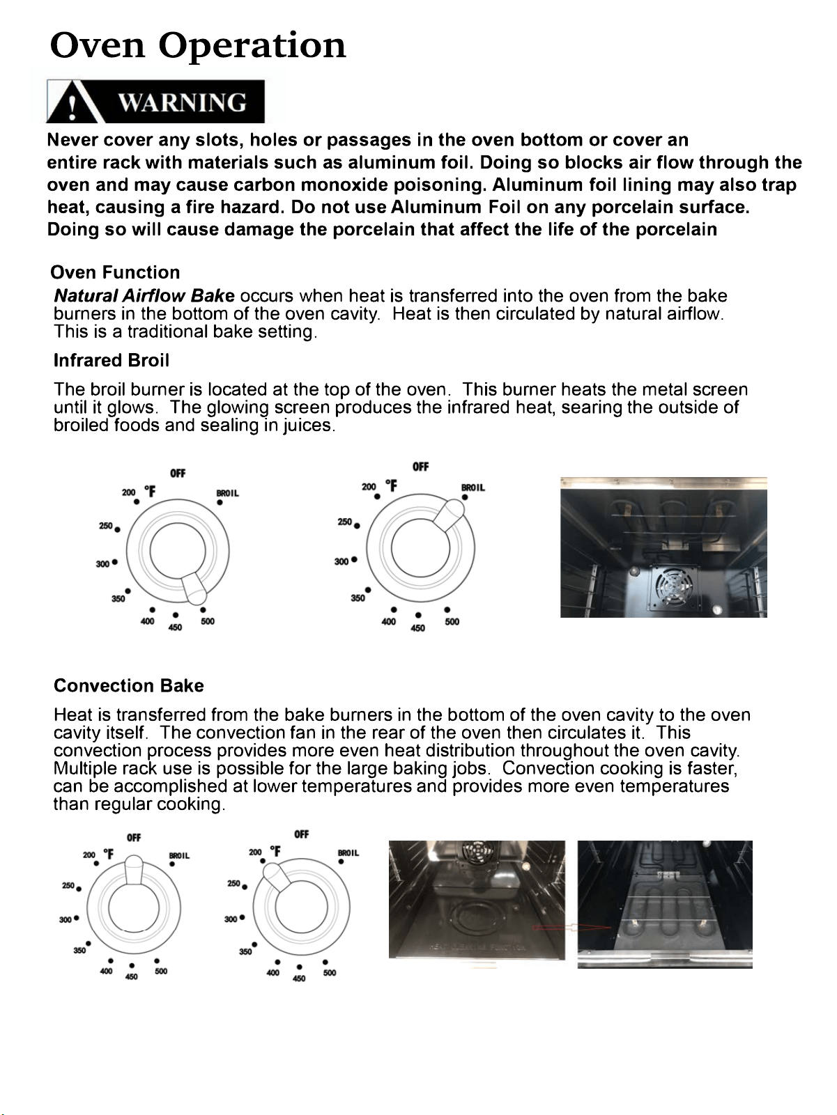
Preheating
To Broil
Setting Broil
DO NOT DO NOT
cover the broil pan insert with foil.
To set the oven to Broil:
Note: Door must be closed during broiling operation.
25
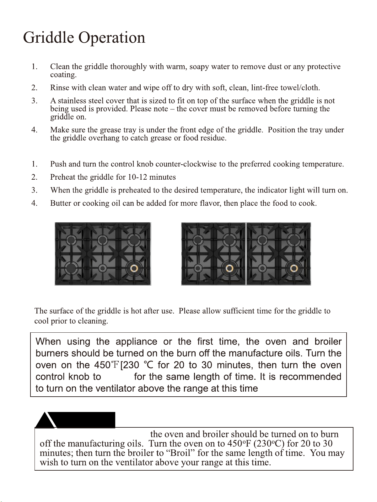
Before Using the Griddle
Use of the Griddle
WARNING
!
Before Baking or Broiling
CAUTION:
“Broil”

26
Cooktop
Control Panel, Door Handle, Control Housing
Oven Window
Porcelain Surfaces
Stainless Steel Surfaces

27
Metal Finishes
Plastic Finishes
Oven Racks
Oven Frame
Oven Gasket
Replacing the Oven Light
Outer Oven Door
Inner Oven Door
28
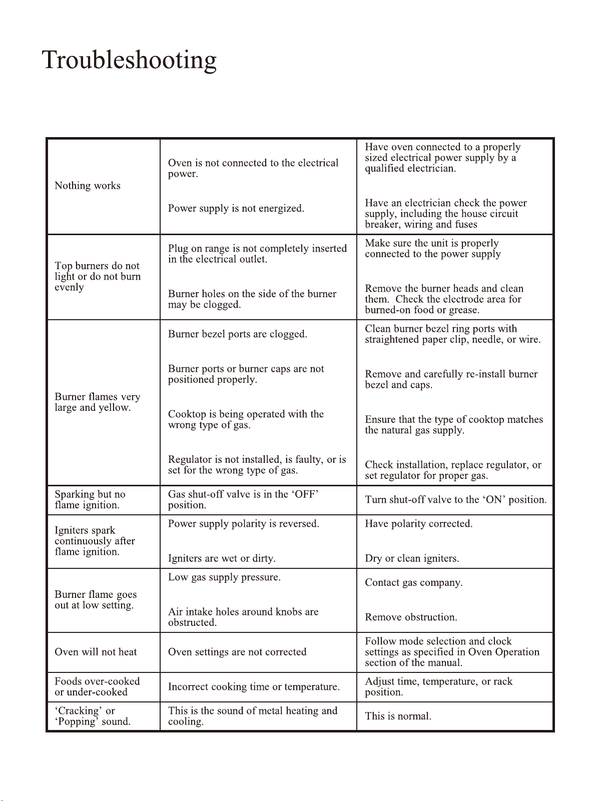
Before you call for service, please review the potential problem / possible causes and
remedies shown in the table below.
29
Top Burner
Top Burner
Top Burner
Top Burner
Top Burner
18Broil
240v,60hz,2000w
240v,60hz,1600w
240v,60hz,3200w
240v,60hz,2800w
240v,60hz,3400w
240v,60hz,2800w
18Oven
30Broil
30Oven
36Broil
36Oven
6,000 BTU L.P Gas
9,000 BTU L.P Gas
12,000 BTU L.P Gas
15,000 BTU L.P Gas
20,000 BTU L.P Gas
Top Burner
Top Burner
Top Burner
Top Burner
Top Burner
18Broil
240v,60hz,2000w
240v,60hz,1600w
240v,60hz,3200w
240v,60hz,2800w
240v,60hz,3400w
240v,60hz,2800w
18Oven
30Broil
30Oven
36Broil
36Oven
6,000 BTU L.P Gas
9,000 BTU L.P Gas
12,000 BTU L.P Gas
15,000 BTU L.P Gas
20,000 BTU L.P Gas
[0.74mm]
[0.90mm]
[1.0mm]
[1.16mm]
[0.89*2+0.53mm]
[1.07mm]
[1.36mm]
[1.57mm]
[1.79mm]
[1.36*2+0.73mm]
30
Exchange end

31
32

®