06/2024
Read these instructions carefully before using your appliance, and keep it carefully.
If you follow the instructions, your appliance will provide you with many years of good service.
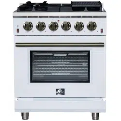
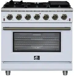
RANGE
MODEL NUMBER SERIES
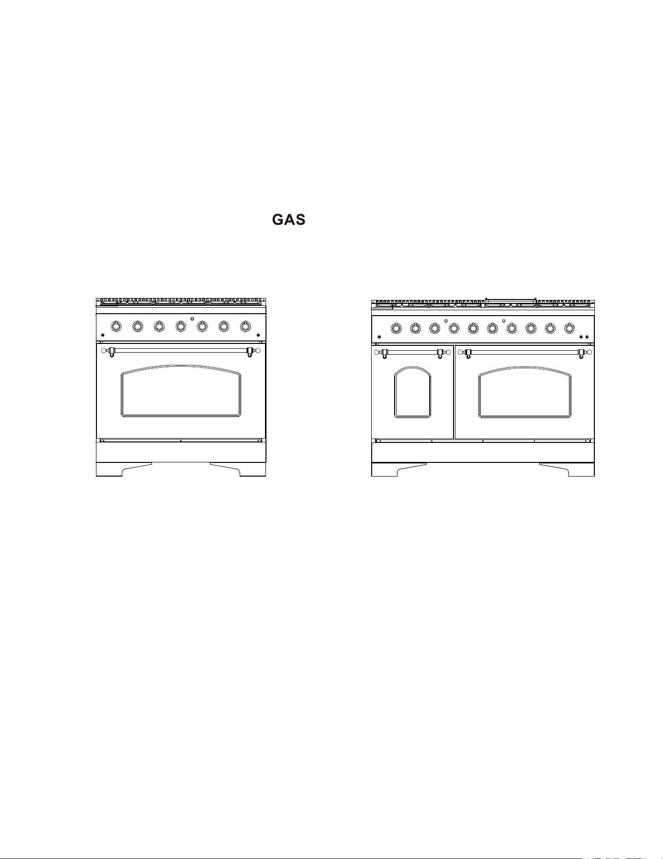
JK36A1/JK48A1
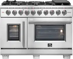
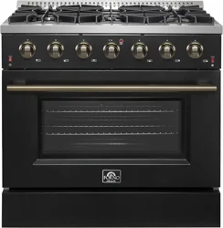
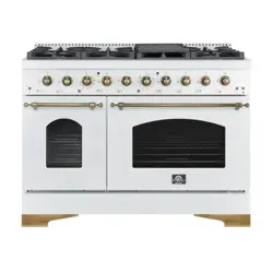
FFSGS6219-36WHT | FFSGS6219-36BLK | FFSGS6219-48WHT | FFSGS6219-48BLK
INSTRUCTION MANUAL
ENGLISH
®

Contents
Safety Instructions …………………………………………………………….
5~7
Unpackage instruction …………………………………………………………8
Installation Instructions ……………………………………………………….
9~18
19~21
22~23
24
25
26~27
28
29~33
Cooktop Operation ……………………………………………………………
Oven Operation ……………………………………………………………….
Broiler Operation ……………………………………………………………...
Griddle Operation ……………………………………………………………..
Care & Cleaning ………………………………………………………………
Troub
Ng to LPG Conversion
leshooting ……………………………………………………………….
If the information in this manual is not followed exactly, a fire or an explosion may result
causing property damage, personal injury or even death.
Do not store or use gasoline, liquid propane cylinder or other flammable vapors and
liquids in the vicinity of this appliance.
What to do if you smell gas?
Do not try to light any appliance.
Do not touch any electrical switch.
Do not use any phone in your residence.
Immediately call your gas supplier from a neighbor’s phone. Follow the gas supplier’s
instructions.
If you cannot reach your gas supplier, call the fire department.
For installation and service of your range product, it must be performed by a
licensed installer, an approved service agency or your gas supplier.
WARNING
!
2
Customer Care
.................................................................................................. 4
3
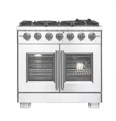
MODEL NUMBER SERIES MODEL NUMBER SERIES
JK36A1
FFSGS6319-36WHT
FFSGS6319-36BLK
FFSGS6319-48WHT
FFSGS6319-48BLK
JK48A1
RANGE
Customer Care
Services in Canada and Untied States
4
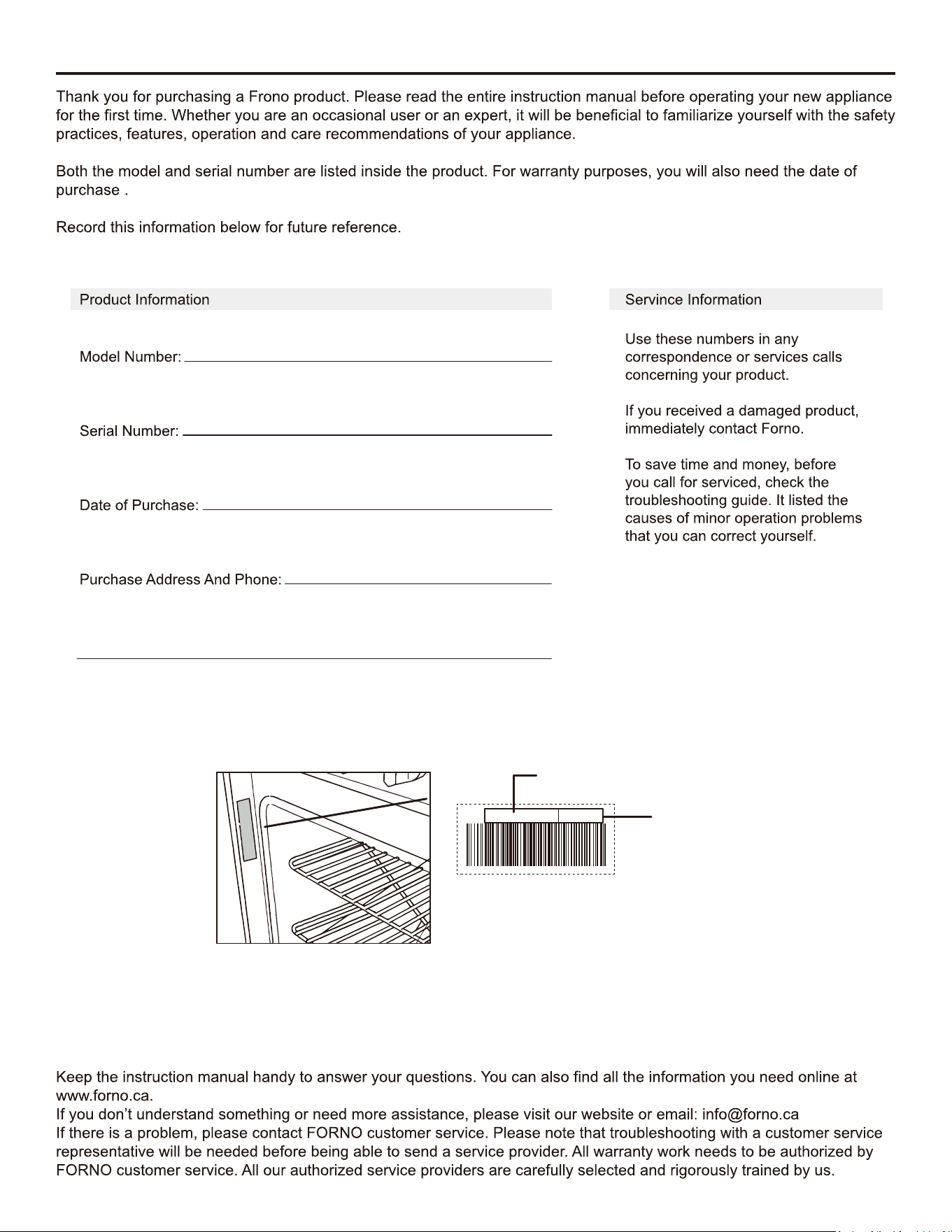
nd SeriaModel And Serial NumberA
S/N:
FFSGS6319-36WHT
XXXXXXX
Model Number
Serial Number
SAFETY INSTRUCTIONS
Definitions
–
5
SAFETY INSTRUCTIONS
What to do if you smell gas?
Immediately call your gas supplier from a neighbor’s phone.
Follow the gas supplier’s instructions.
!
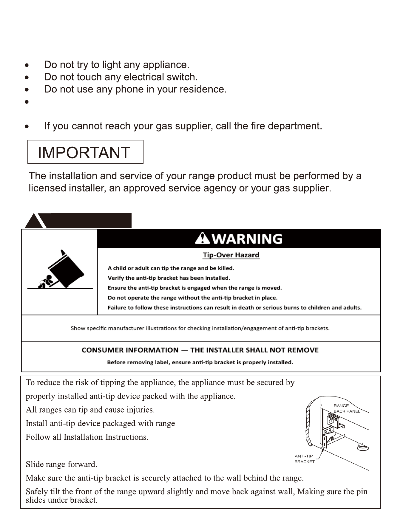
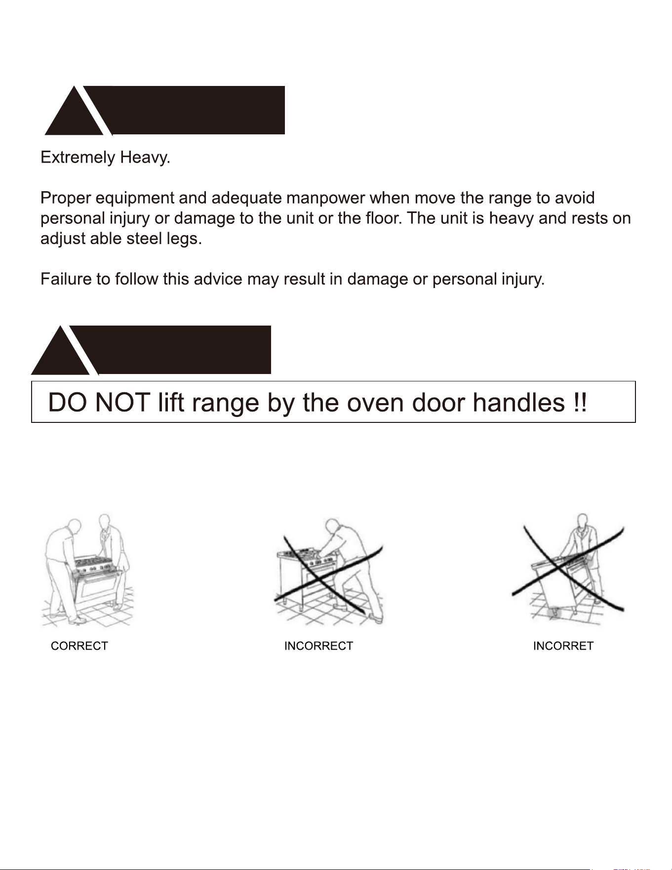
Make sure the anti-tip bracket is installed:
WARNING
!
6
SAFETY INSTRUCTIONS
ELECTRICAL GROUNDING INSTRUCTIONS
7
UNPACKING AND HANDLING
WARNING
!
WARNING
!
8
INSTALLATION AND OPERATION INSTRUCTIONS
9
INSTALLATION INSTRUCTIONS
Gas Supply Requirements
10
11
INSTALLATION INSTRUCTIONS
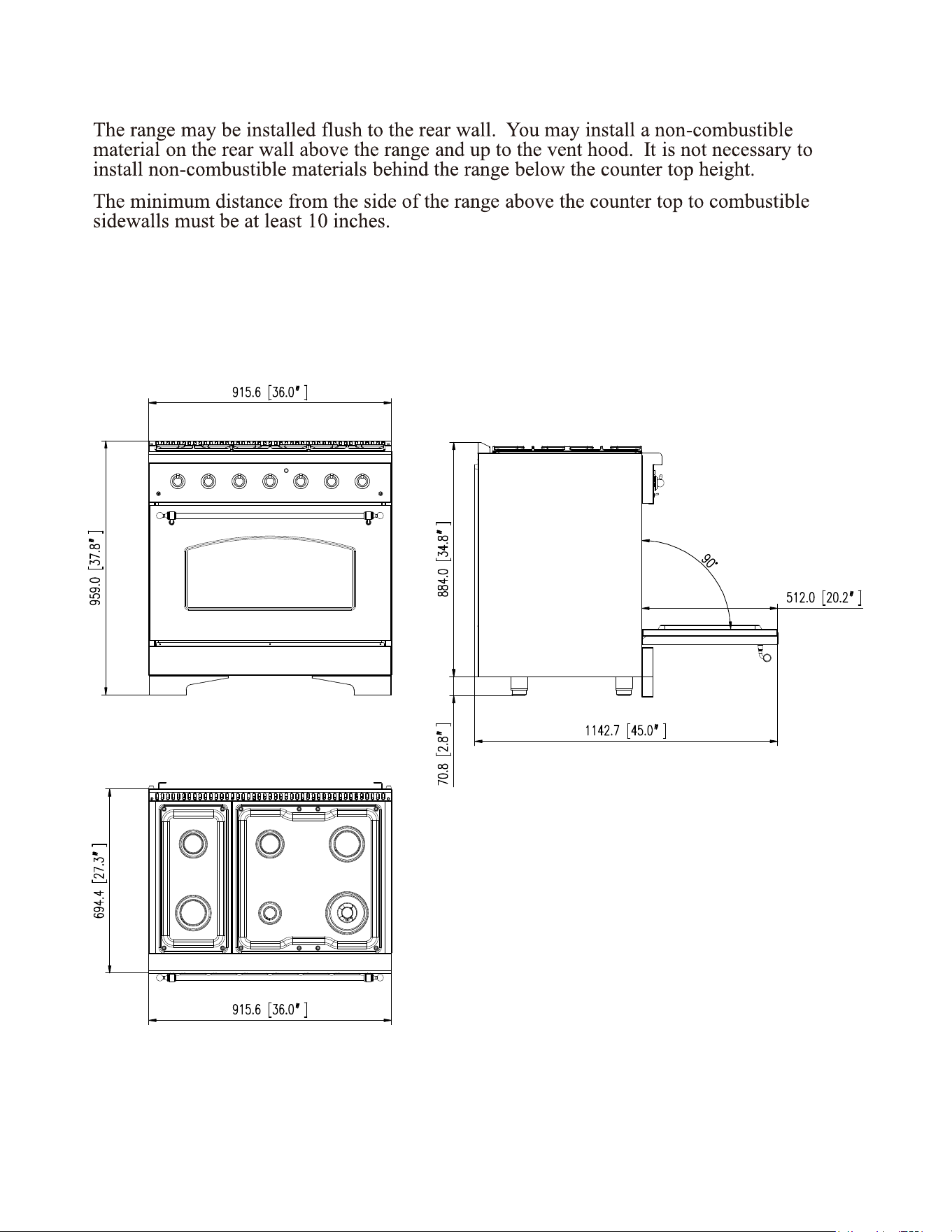
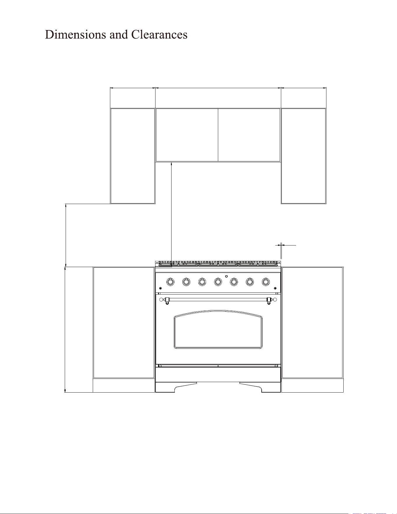
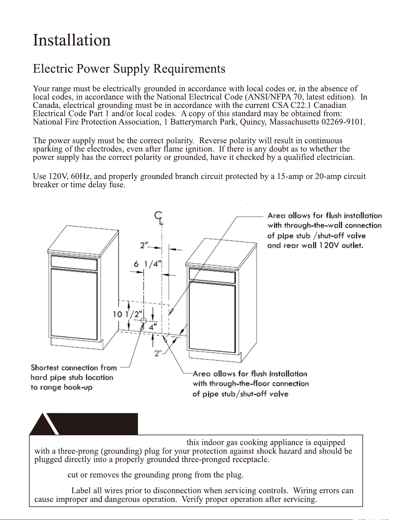
Dimensions and Clearances
INSTALLATION INSTRUCTIONS
*Product features may not match. Image meant for dimension reference only.
FFSGS6219-36WHT
FFSGS6219-36BLK
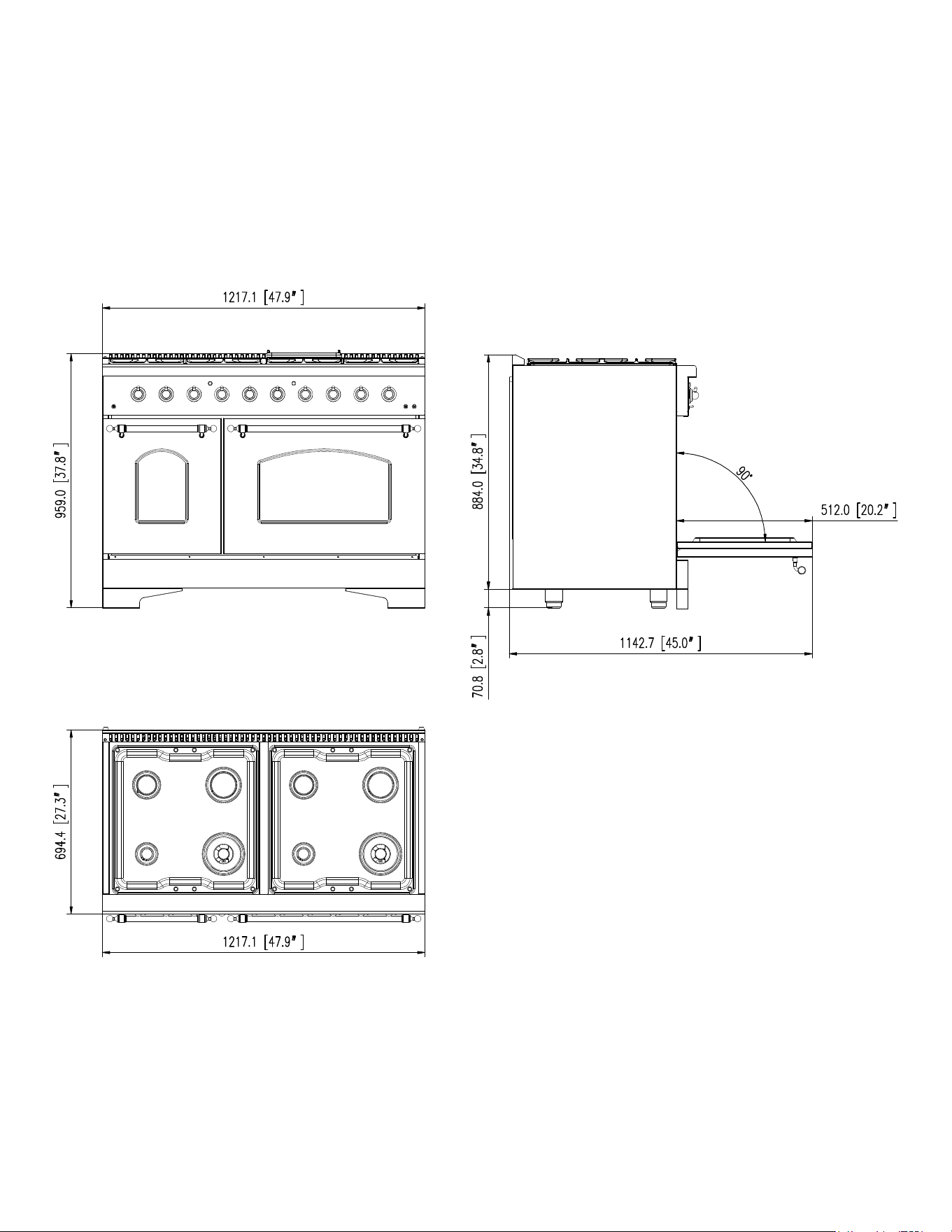
*Product features may not match. Image meant for dimension reference only.
12
FFSGS6219-48WHT
FFSGS6219-48BLK
13”
18”
30”Minimum
2”To wall on either side
sealed burner models
Minium to
cabinets on
either side
of the range
36”
13”
36”
13
FFSGS6219-36WHT
FFSGS6219-36BLK
FFSGS6219-48WHT
FFSGS6219-48BLK
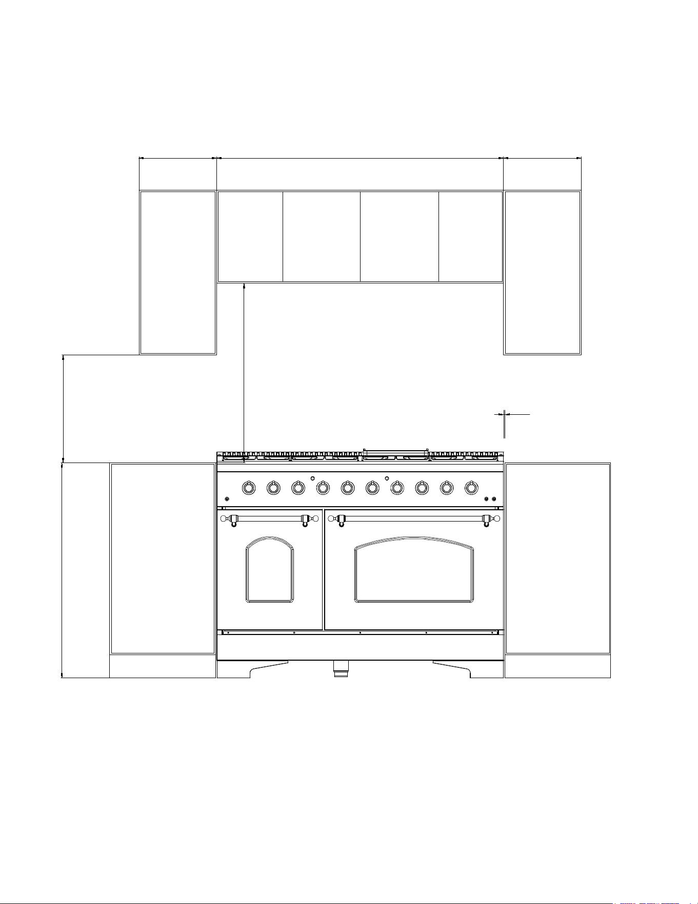
14
30”Minimum
To wall on either side
sealed burner models
Minium to
cabinets on
either side
of the range
2”
13”
18”
36”
13”48”
FFSGS6219-48WHT
FFSGS6219-48BLK
15
Installation Instructions
Bcfore using your range
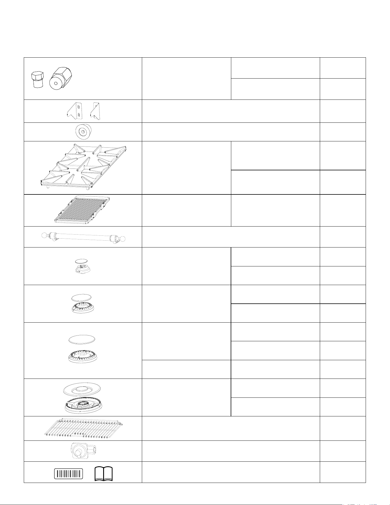
1.Remove all packaging material.
2.Check to make sure you have all of the accessories listed below
LPG injector
FFSGS6219-36
FFSGS6219-48
1 set
1 set
Anti-tip bracket and screws
Wall-against mat
Burner Grills
Cook plate(Griddle)
1 set
2 pieces
3 pieces
4 pieces
1 piece
1 piece
oven door handle
(*2 pcs for FFSGS6219-48 )
Burner & Cap
(9000BTU)
Burner & Cap
(6000BTU)
Burner & Cap
(15000BTU)
Burner & Cap
(12000BTU)
Burner & Cap
(20000BTU)
Baking rack (*4 pcs for FFSGS6219-48)
Regulator(pre-installed)
Serial Number Sticker & Instruction Manual
2 pieces
1 piece
1 set
2 sets
1 set
2 sets
1 set
2 sets
1 set
FFSGS6219-36
FFSGS6219-48
FFSGS6219-48
FFSGS6219-36
FFSGS6219-48
FFSGS6219-36
FFSGS6219-48
FFSGS6219-36
FFSGS6219-48
1 set
FFSGS6219-36
2 sets
1 set
FFSGS6219-36
FFSGS6219-48
(FFSGS6219-36:
0.53,0.74,0.89,0.90,
0.94,1.00,1.16,1.40)
(FFSGS6219-48:
0.53,0.74,0.89,0.90,
0.94,1.00,1.09,1.40)
WARNING
!
Electrical Grounding Instructions:
Do Not
Caution
16
•
•
•
•
• Install male ½” flare union adapter to ½” NPT internal thread elbow at inlet of
thread end of the ½” flare union adapter to the ½” NPT internal thread at inlet of
• Install male ½” or ¾” flare union adapter to the NPT internal thread of the manual
•
• When all connections have been made, check that all range controls are in the “off”
• Leak testing of the appliance shall be conducted according to the manufacture’s
• The appliance must be isolated from the building’s gas supply piping system by
INSTALLATION INSTRUCTIONS
17
18
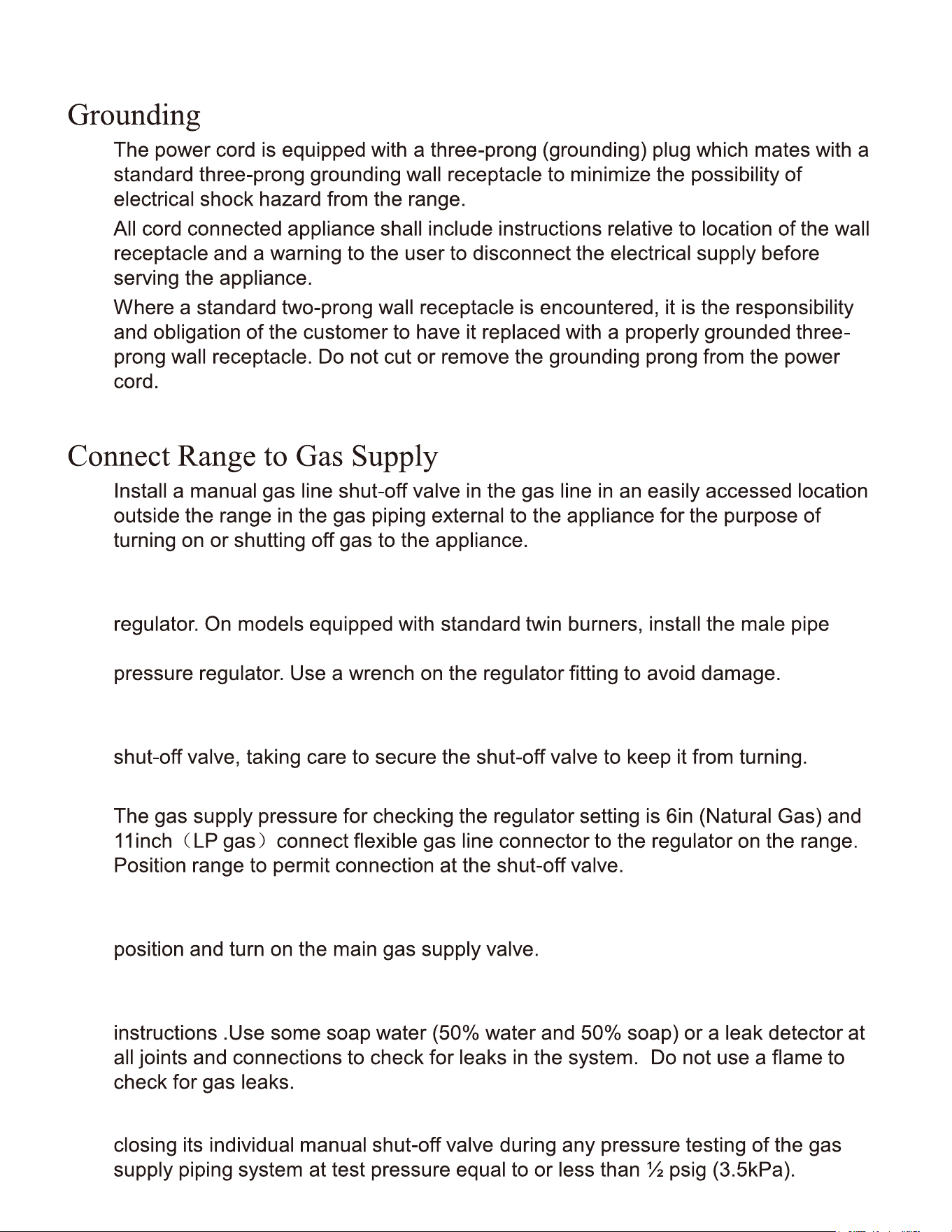
After Installation:
Hood/Composite Overlay Install
30”(762)min
36”(914)max
66”-72”
(1676-1829)
30”(762)min
36”(914)max
66”-72”
(1676-1829)
36“
914
36“
914
WALL
INSTALLATION
wood compsite overtay
ISLAND
INSTALLATION
wood compsite overtay
metal hoodmetal hood
countertop
countertop
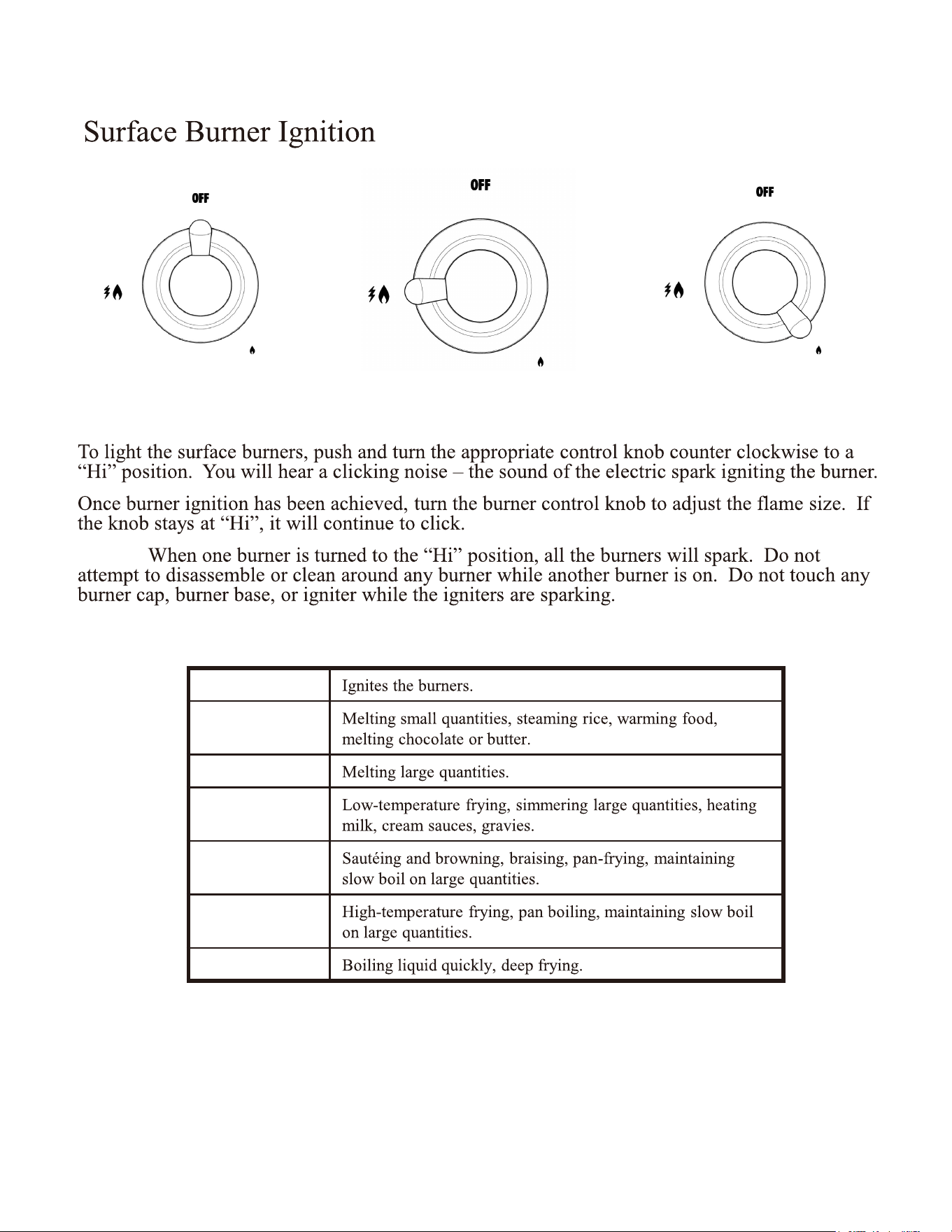
Push to release gas.
Adjust to appropriate
flame height.
Turn to Ignite and ‘Hi’ position.
NOTE:
Heat Settings:
Hi
Simmer
Low
Low-Medium
Medium
Medium – Hi
Hi
COOKTOP OPERATION
19
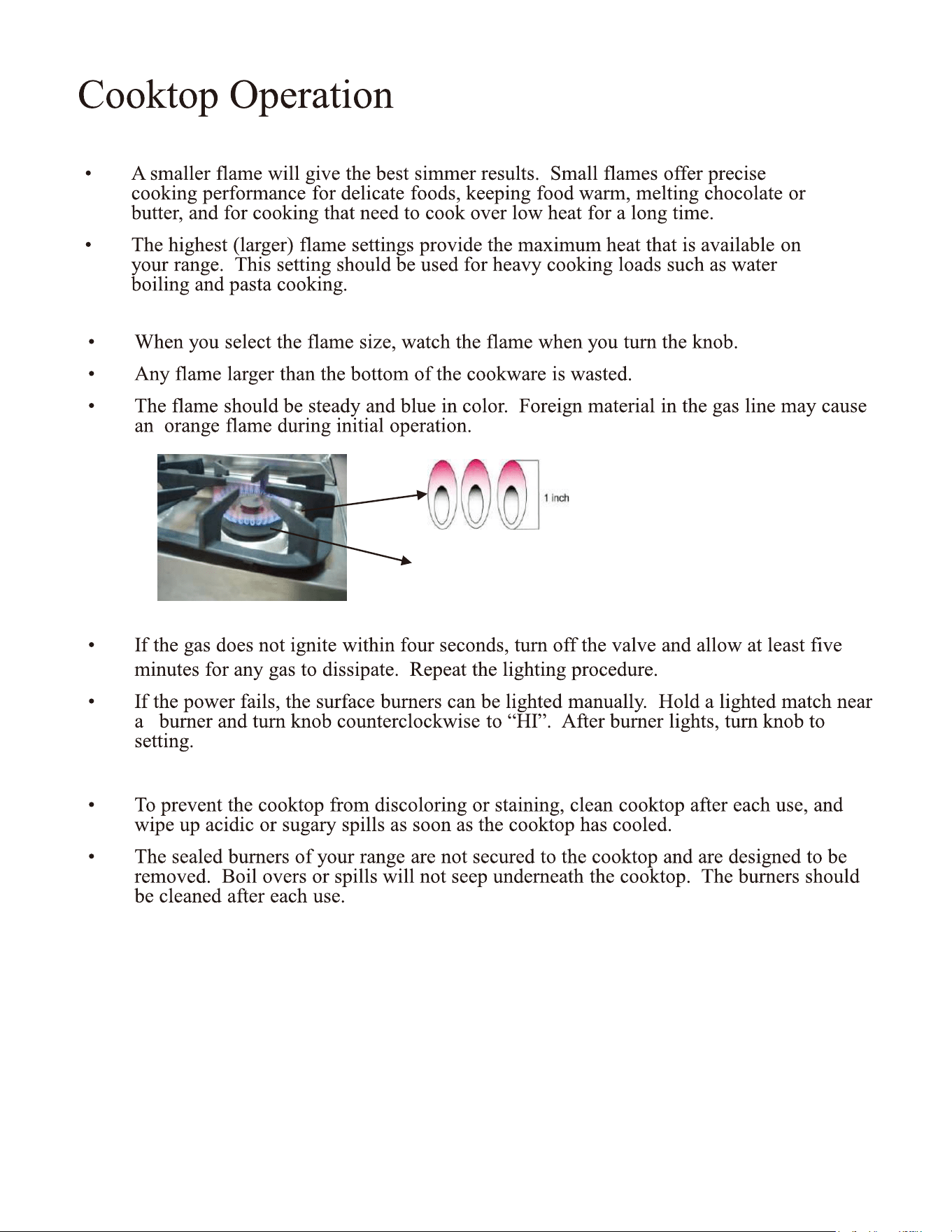
Flame Size
Power Failure
Cooktop
Approximate 1
1/2“ Flame Height
Simmer and Boil
20
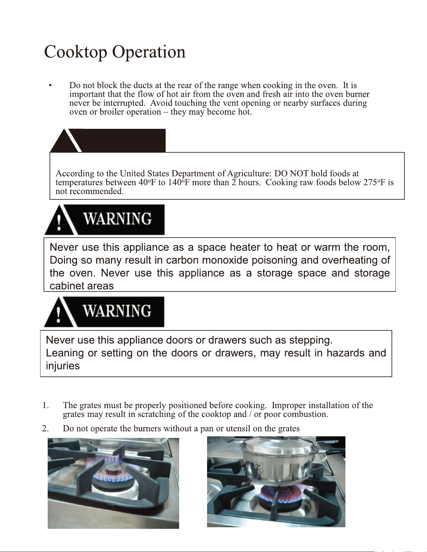
Burner Grates
Oven Vent
WARNING
!
FOOD SAFETY
21
Never cover any slots, holes or passages in the oven bottom or cover an
entire rack with materials such as aluminum foil. Doing so blocks air flow through the
oven and may cause carbon monoxide poisoning. Aluminum foil lining may also trap
heat, causing a fire hazard. Do not use Aluminum Foil on any porcelain surface.
Doing so will damage the porcelain
Oven Function
Natural Airflow Bake
Infrared Broil
22
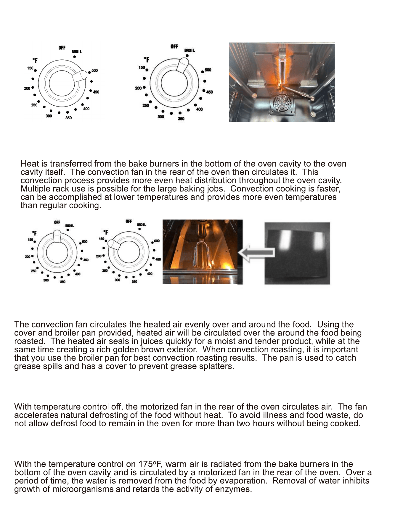
Convection Roast
Convection Defrost
Convection Dehydrate
Convection Bake
23
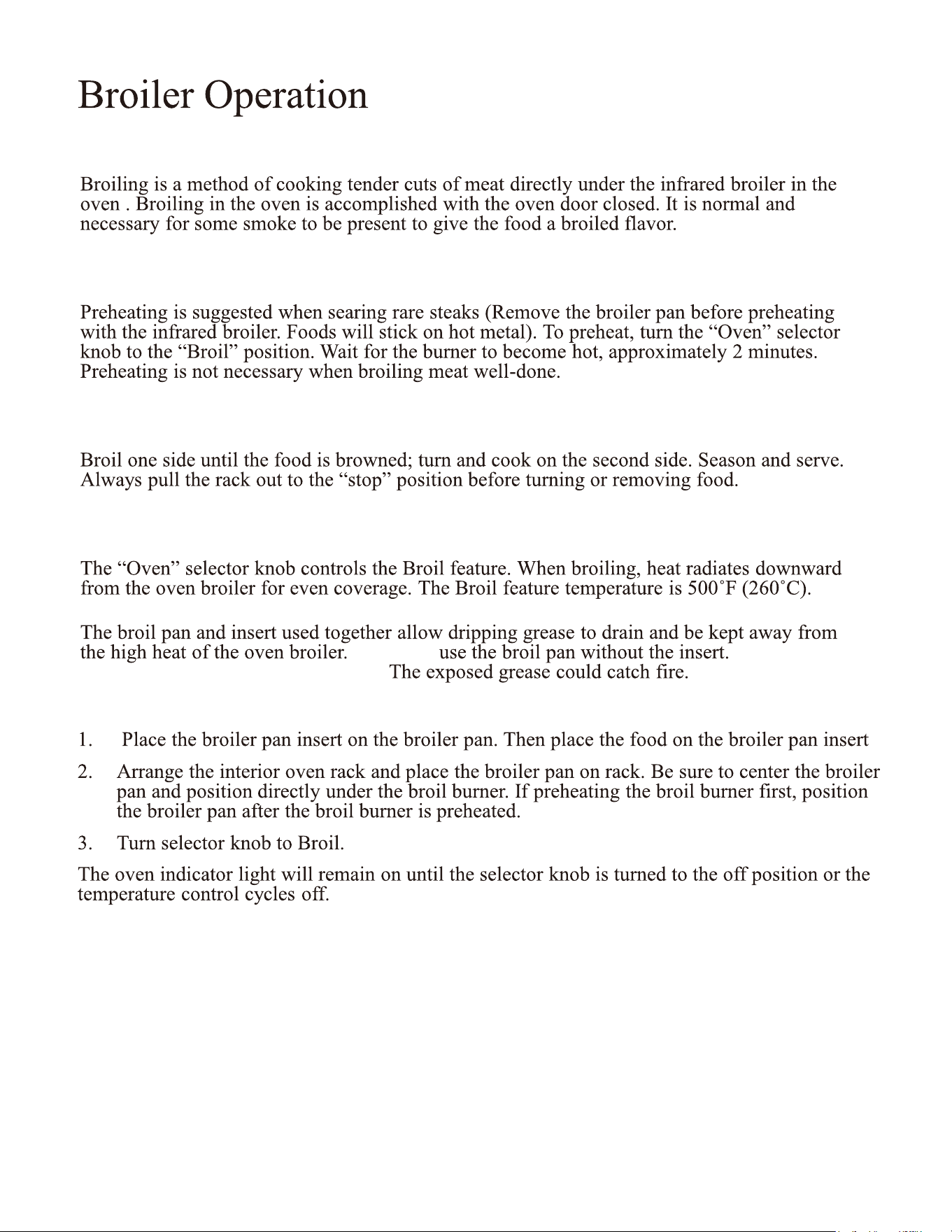
Preheating
To Broil
Setting Broil
DO NOT DO NOT
cover the broil pan insert with foil.
To set the oven to Broil:
Note: Door must be closed during broiling operation.
24
Before Using the Griddle
Use of the Griddle
WARNING
!
Before Baking or Broiling
CAUTION:
“Broil”
25
Cooktop
Control Panel, Door Handle, Control Housing
Oven Window
Porcelain Surfaces
Stainless Steel Surfaces
26
Metal Finishes
Plastic Finishes
Oven Racks
Oven Frame
Oven Gasket
Replacing the Oven Light
Outer Oven Door
Inner Oven Door
27
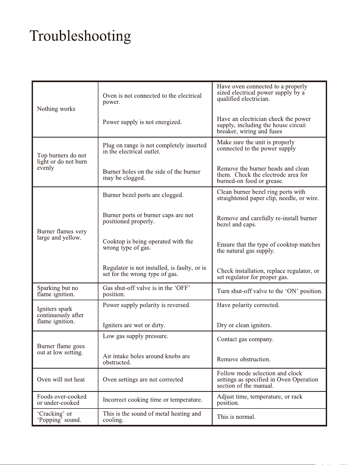
Before you call for service, please review the potential problem / possible causes and
remedies shown in the table below.
28
Instructions for Converting Range to Operate on Liquefied Petroleum Gas
INSTALLATION AND SERVICES MUST BE PERFORMED BY A QUALIFIED INSTALLER
IMPORTANT: SAVE INSTRUCTION MANUAL FOR THE LOCAL INSPECTOR’S USE.
READ AND SAVE THESE
INSTRUCTIONS
FOR FUTURE REFERENCE
This conversion kit must be installed by a qualified service
technician in accordance with the manufacturer's instructions and all applicable
codes and requirements of the authority having jurisdiction. Failure to follow
instructions may result in fire, explosion or production of carbon monoxide causing
property damage, personal injury or loss of life. The qualified service agency is
responsible for the proper installation of this kit. The installation is not proper and
complete until the operation of the converted appliance is checked as specified in
the manufacturer's instructions supplied with this kit.
Before proceeding with the conversion, shut off the gas supply
before disconnecting electrical power to the range. Be sure power supplies are off
before installing the conversion kit. Failure to do so could cause serious bodily injury.
Determine the combination of top burners that are featured on your range. Identify
the parts you need from this kit to complete the L.P. co
nversion. When burners are
converted from natural to L.P. the BTU ratings are as follows:
Top Burner 6,000 BTU L.P. Gas [ 0.74mm ]
Top Burner 9,000 BTU L.P. Gas [ 0.90mm ]Top Burner 9,000 BTU L.P. Gas [ 0.90mm ]
Top Burner 12,000 BTU L.P. Gas [ 1.0mm ]
Top Burner 15,000 BTU L.P. Gas [ 1.16mm ]
Top Burner 20,000 .0[ saG .P.L UTB 89*2+0.53mm]
Broil Burner 10,000 BTU L.P. Gas [0.94mm]
Oven Burner 22,000 BTU L.P. Gas [1.40mm]
Straight Burner 14,000 BTU L.P. Gas [ 1.09mm ]
*Note: For operation at elevations above 2000ft., appliance rating shall be reduced at the rate of 4%
for each 1000 ft. above sea level .
The original orifices are Nature Gas:
Top Burner 6,000 BTU [ 1.07mm ]
Top Burner 9,000 BTU [ 1.36mm ]
Top Burner 12,000 BTU [ 1.57mm ]
Top Burner 15,000 BTU [ 1.79mm ]
Top Burner 20,000 BTU [ 1.36*2+0.73mm ]
Oven Burner 22,000BTU [ 2.13mm ]
Broil Burner 10,000 BTU [1.42mm]
Straight Burner 14,000 BTU [ 1.68mm]
Tools Required for L.P. Conversion:
2mm Allen Wrench
3/8 & 1/2 & 5/8” [19mm] Open End Wrench
1/8” Wide Flat Blade Screwdriver
Philips Screwdriver
7mm Nut Driver
1/4 Nut Driver
Adjustable wrench.
IMPORTANT: After replacing the natural gas to LP orifices, be sure to keep the original
factory installed natural gas orifices for future range conversion back to natural gas.
29
Instructions for Converting Range to Operate on Liquefied Petroleum Gas
1. Convert the Pressure Regulator
To access the gas regulator, pull the
range away from the cabinet wall.
The gas regulator is located at the
bottom right corner of the range.
a. Electrical shock hazard can occur
and result in injury or death.
Disconnect electrical power to the
range before servicing. Do not
remove regulator or allow it to
turn during
servicing.
b. Un
screw the cap from the regulator.
Do not remove the spring from
the regulator.
c. Unscrew the insert from the cap and
turn it over so the longer stem is
facing the cap. Replace insert on the
cap. Replace the cap on the
regulator.
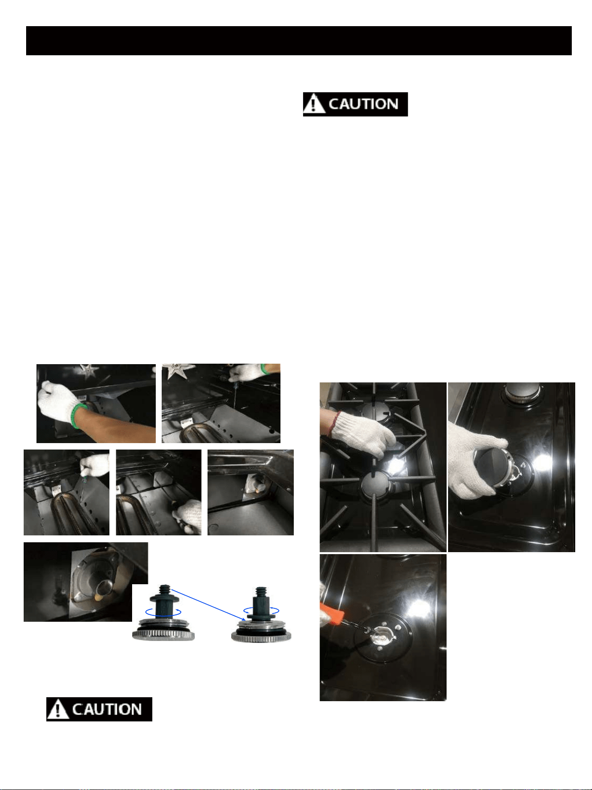
2. Convert Top Burner for LP/ Propane Gas
Save the natural gas orifices
removed from the appliance for possible future
conversions to natural gas. You should use the
following p
rocess to c
onvert to Natural gas.
Take extra care when handling steel parts.
a. Remove cooking grates, burner caps
and inner burner rings.
b. Lift off outer burner heads and burner
bases.
c. Remove the factory installed natural gas
orifices from the center of the orifice
holders using a 7mm nut driver.
Remember to keep the original natural
gas orifices for future conversions back
to natural gas. Replace the LP orifice in
each ori
fice holder. Tighten each orifice
until snug. Use caution not to over
tighten.
Position for LPPosition for NG
Care should be taken when removing and replacing gas components. Use proper
support to prevent damage to components.
30
Exchange end
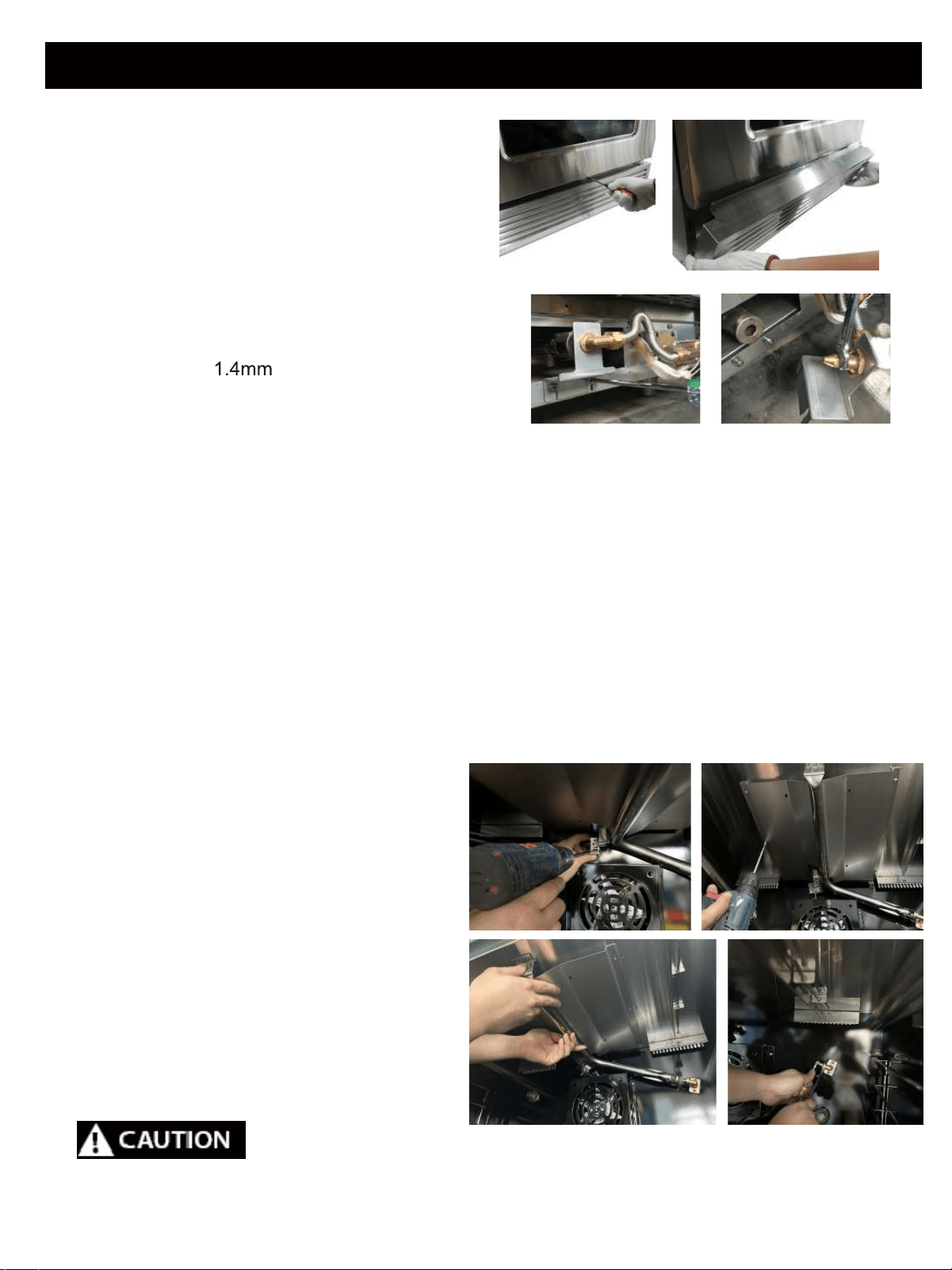
3. Convert Oven Burner Orifice for
LP/Propane Gas
a. Remove 3 screws between the kick
panel and the oven door . Hold the toe
kick panel on both ends and slowly pull
away towards the front.
b. Remove 2 screws which holding the
orifice bracket and locate the orifice.
Remove orifice using an adjustable
wrench. Replace with oven burner
orifice, size
and tighten. Replace
the orifice bracket, aligning the new
orifices into the air shutter of the oven
burner.
* Repeat upon steps for 18”oven .
4. Convert Broil Burner Orifice for
LP/Propane Gas
a. Remove 2 screws which fixing the
orifice bracket and locate the orifice.
b. Using a 5/8”or 19mm open
wrench, remove the gas line from
the orifice holder. Using a ½”open
wrench, remove the orifice from the
orifice holder. Replace with oven
broiler orifice size 0.94mm.
Care should be taken when removing and replacing gas components. Use proper
support to prevent damage to components.
Instructions for Converting Range to Operate on Liquefied Petroleum Gas
31
Instructions for Converting Range to Operate on Liquefied Petroleum Gas
5. Convert Gas Valves for LP/Propane
Gas
a. Remove control knobs.
Care should be taken when removing and replacing gas components. Use proper
support to prevent damage to components.
This cooking rang can be used with LPG(Liquid Propane Gas)
and NG (Natural Gas). It is shipped from the factory adjusted for use
with NG. Conversion nozzles are included in this plas
c bag. Follow
the instruc
ons in the manual (page 28 32) for gas
conversion.
A
en on: Af x this label as close as possible to the conversion plate
on the gas range.
.............................................................................................................
Ga range model: ________________________________________
This range was converted on_____________ (day/month/year)to
LPG by_________________________________
_______________________________________________________
(name and address of company making this conversion).
which accepts the liability that this conversion has been
properly made.
LPG Supply Pressure 10” w.c.
This cooking rang
can be used with LPG(Liquid Propane Gas)
(GPL) et du gaz naturel. L'appareil est réglé pour une u
lisa on
avec du gaz nature
l lorsqu'il qui
e l'usine. Les buses de
conversion se trouvent dans ce sac en plas
que.
Veuillez suivre les instruc
ons fournies dans le guide
(pnges 28 à 32) pour la conversion au gaz.
A
en on : Posez ce e é que e le plus près possible delaplaque de
conversion située sur la cuisinière.
...............................................................................................................
Modèle de cuisinière_______________________________________
Ce
e cuisiniére a été conver e le_____________________________
(jour/mois/année) po
ur une u�lisa on avec du GPL par:__________
________________________________________________________
(nom et adresse del’ entreprise responsable de la conversion).
qui assume laresponsabilité que la conversion a été
e
ectuéecorrectement.
Pression de I'alimenta
on enGPL: 10 po (25 cm)
32

Instructions for Converting Range to Operate on Liquefied Petroleum Gas
Checking for Manifold Gas Pressure
If it is necessary to check the manifold
gas pressure, remove the burner cap,
inner ring, outer burner head and burner
base of the right front top burner and
connect a manometer (water gauge) or
other pressure test device to the burner
orifice. Use a rubber hose with inside
diameter of approximately ¼ ” and hold
the end of the tube tight
over the orifice.
Turn the gas valve on. For a more
accurate pressure check, have at least
two (2) other top burners burning. Be
sure that the gas supply (inlet) pressure is
at least one inch above the specified
manifold pressure. The gas supply
6. Reconnect Gas and Electrical Supply
to Range
Leak testing of the appliance shall be
conducted according to the installation
instructions provid
ed with the range.
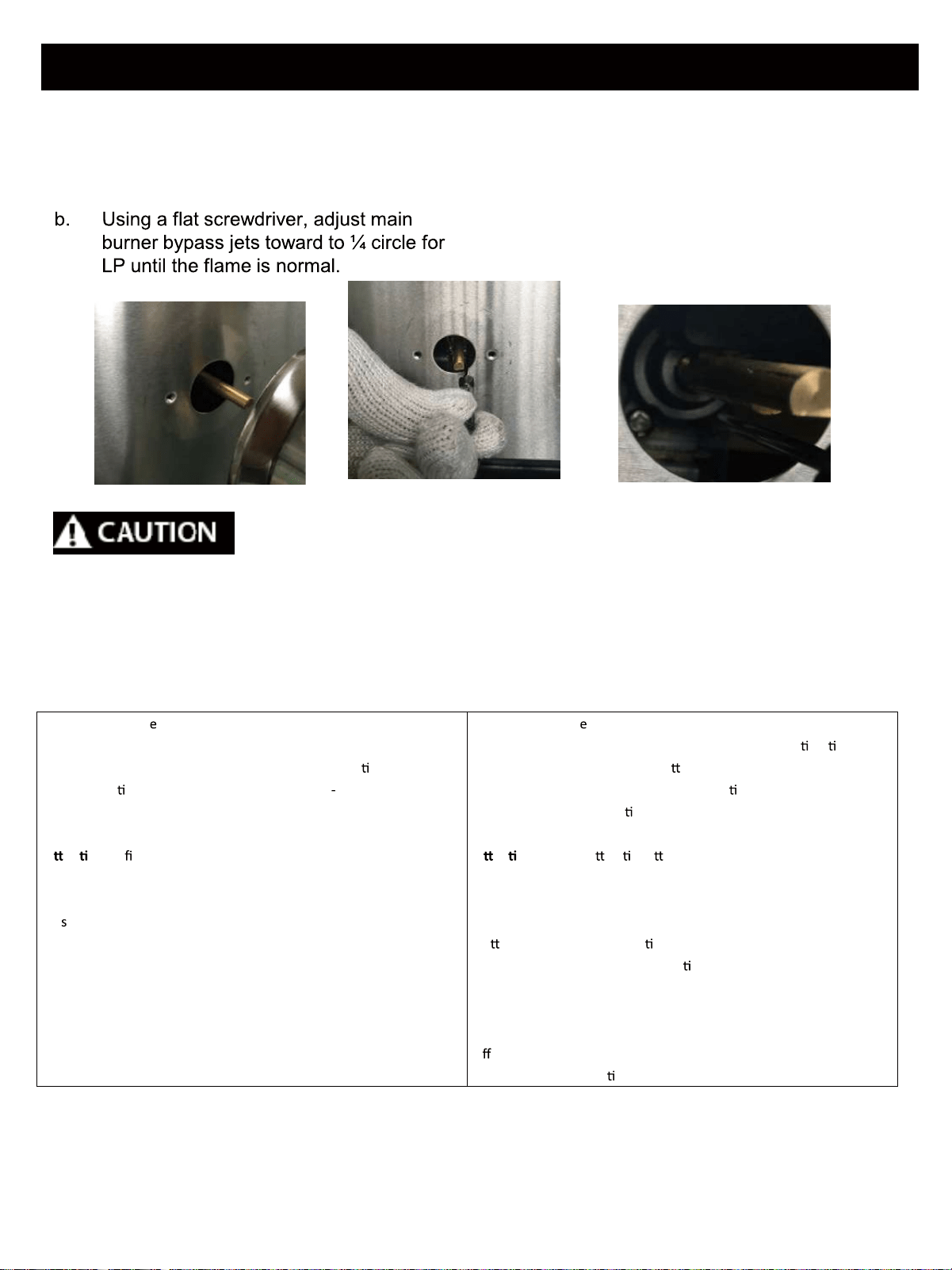
7. Air Shutter Oven Burner
The air shutter for the oven burner may
need adjustment, especially if the unit has
been converted for use with LP/Propane
gas. The approximate flame length of the
oven burner is one inch (distinct inner blue
flame).
a. With the toe
tick removed, set the
oven to bake at 350 °F and observe
the flame. If the flame is yellow in
color, increase the air shutter
opening size.
If the flame is blue
lifting away from the burner, reduce
the air shutter opening size.
b. Turn off oven and allow it to cool
before adjusting the air shutter. To
adjust, loosen the lock screw,
reposition the air shutter and
tighten the lock screw. Retest the
To determine if the oven burner flame is
proper:
manifold pressure. The gas supply
pressure should never be over 14” water
column. When properly adjusted
the
manifold water column pressure is 10”
for LP/Propane gas or 5” for Natural
Gas
Do not use a flame to check for gas
leaks
a. Disconnect the range and its
individual shut -off valve from the gas
supply piping system during any
pressure of that system at test
pressures greater than 14” of water
column pressure (approximately ½ ”
psig)
b. The appliance must be isolated f
rom
the gas supply piping system by closing
its individua
l manual shut -off valve
during any pressure testing of the supply
system at test pressure equal to or less
than 14” water column pressure
(approximately ½ ” psig)
tighten the lock screw. Retest the
burner by repeating the steps above.
When the burner flame is a distinct
blue color burning steadily, the air
shutter is adjusted correctly.
8. Installation of New LP / Propane
Rating / Serial Plate
Record the model and serial number
on the LP / Propane Rating serial
plate provided in this kit. The
information can be obtained from the
existing Rating / Serial plate. Place
the
new plate as close as possible to
the
existing Rating / Serial plate on
the range.
33

®