FORNO COMMERCIAL
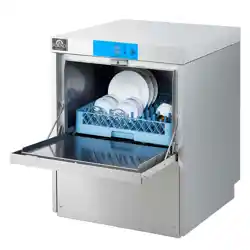
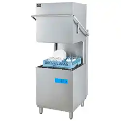
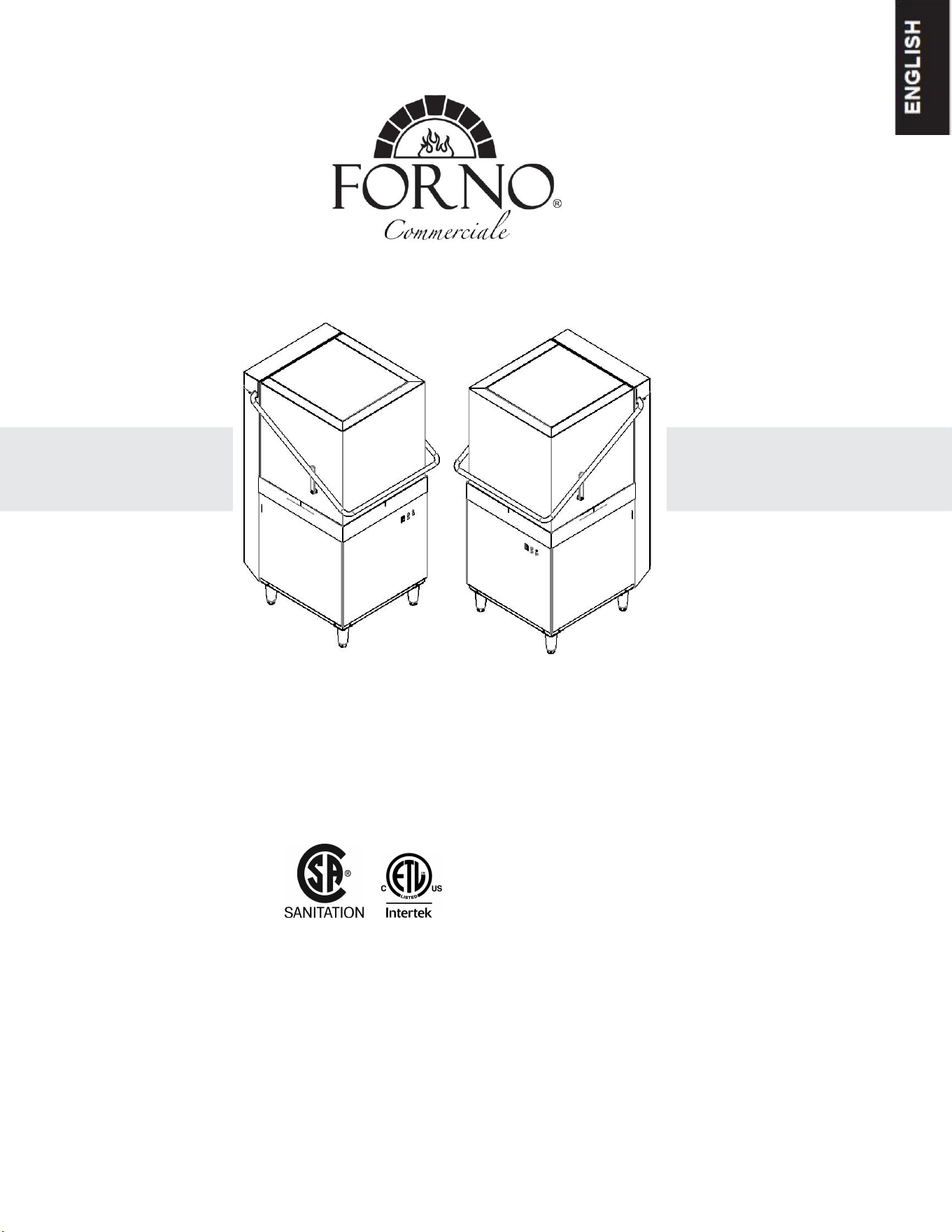
Hood type Dishwasher
Model# : FCMDW0031
INSTRUCTION MANUAL
Read these instructions carefully before using your appliance, and keep it carefully.
If you follow the instructions, your appliance will provide you with many years of good service.
CONFORMS TO UL STANDARD 921
& CERTIFIED TO CSA STD C22.2
NO.168
07/2026
NSF/ANSI 3
306271
5027459

TABLE OF CONTENTS
1 Important Safety Instructions ........................................................................................................ 1
2 Product Dimension
.........................................................................................................................
2
3 Names of Parts and Accessories .................................................................................................. 3
4 Operating Instructions
................................................................................................................
4-25
4.1 NOTES ON THE DOCUMENTATION
......................................................................................
4
4.2 Layout of the documentation....................................................................................................... 4
4.3 Representative convention
.........................................................................................................
4
4.4 SAFETY INSTRUCTIONS AND REGULATIONS...................................................................5
4.4.1 Safety instructions and warning notices ............................................................................... 5
4.4.2 Hazard levels
............................................................................................................................
5
4.4.3 Layout of warning notices
.......................................................................................................
5
4.5 Basic safety instructions
..............................................................................................................
5
4.5.1 Product safety
...........................................................................................................................
5
4.5.2 Personnel qualification..............................................................................................................5
4.5.3 Product-specific hazards......................................................................................................... 6
4.6 Property damage
..........................................................................................................................
6
4.7 PRODUCT DESCRIPTION
....................................................................................................
6
4.8 General
.........................................................................................................................................
6
4.9 Designation .................................................................................................................................. 7
4.10 Technical specifications............................................................................................................. 7
4.11 CONTROLS
.............................................................................................................................
8
4.12 INSTALLATION ...................................................................................................................... 9
4.12.1 Personnel qualification ...........................................................................................................9
4.12.2 Special safety instructions
....................................................................................................
9
4.12.3 Transporting to the installation location ............................................................................... 9
4.12.4 Unpacking
..................................................................................................................................
9
4.13 Installing the machine
..............................................................................................................
10
4.13.1 Installation Codes
.................................................................................................................
10
4.13.2 Attaching legs ....................................................................................................................... 10
4.13.3 Location ............................................................................................................................... 10
4.13.4 Corner Installation.................................................................................................................11
4.13.5 Rack guide installation..........................................................................................................11
4.14 Connecting the water
................................................................................................................
12
4.14.1 Water Requirements............................................................................................................. 12
4.14.2 Water Connection ........................................................................................................... 12-13
4.15 Connecting the drain ......................................................................................................... 14-15

4.16 Venting Requirements
............................................................................................................
16
4.16.1 Rate of Exhaust Flow Calculations.................................................................................... 16
4.17 Connecting to the power supply............................................................................................. 17
4.17.1 Electrical Data ......................................................................................................................17
4.17.2 Electrical Connection ......................................................................................................... 18
4.18 CHEMICAL SUPPLY SET UP ............................................................................................ 18
4.18.1 Personnel qualification ....................................................................................................... 18
4.18.2 Checking the chemical supply tubing .................................................................................19
4.18.3 Setup of external chemical bottles/buckets ....................................................................... 19
4.18.4 Filling chemical tubing............................................................................................................19
4.19 OPERATION ..........................................................................................................................20
4.19.1 Personnel qualification...........................................................................................................20
4.19.2 Special safety instructions..................................................................................................... 20
4.19.3 Notes for optimal washing result...........................................................................................20
4.19.4 Preparation for washing
.........................................................................................................
20
4.19.5 Preparing the ware for washing
...........................................................................................
21
4.20 Washing
......................................................................................................................................
22
4.21 Switch off machine.....................................................................................................................22
4.22 Daily cleaning or after each meal period................................................................................22
4.23 SETTINGS............................................................................................................................... 23
4.23.1 Overview of operator menu................................................................................................... 23
4.23.2 Opening the operator menu
..................................................................................................
24
4.24 Detergent and Rinse Aid Dispensing...................................................................................... 25
4.24.1 Setting detergent dispensing
.................................................................................................
25
4.24.2 Setting rinse aid dispensing.................................................................................................. 25
4.24.3 Priming detergent and rinse aid dispensing pump
............................................................
25
5、Cleaning and Maintenance
..............................................................................................................
26
5.1 Weekly cleaning .......................................................................................................................... 26
5.2 Removing hard water deposits (Deliming)l ...............................................................................26
6
、
Troubleshooting ..........................................................................................................................27-28
6.1 Informationr .....................................................................................................................................27
6.2 TROUBLESHOOTING GUIDE ................................................................................................... 28
7
、
Warranty .......................................................................................................................................29-30
Customer Care
Thank you for purchasing a Forno product. Please read the entire instruction manual before operating your new appliance
for the first time, Whether you are an occasional user or an expert, it will be beneficial to familiarize yourself with the safety
practices,features, operation and care recommendations of your appliance.
Both the model and serial number are listed inside the product. For warranty purposes, you will also need the date of
purchase .
Record this information below for future reference.
Product Information
Model Number :
Serial Number :
Date of Purchase :
Service Information
Use these numbers in any
correspondence or services calls
concerning your product.
If you received a damaged product,
immediately contact Forno.
To save time and money, before
you call for serviced, check the
troubleshooting guide. It listed the
causes of minor operation problems
that you can correct yourself.
Purchase Address And Phone :
_______________________________________________________
“Need some quick help? Simply scan the qr code and get access
to our fast support form. We’re always here to assist you with any
questions or concerns you may have. So, don’t hesitate to reach out!”
Services in Canada and Untied States
Keep the instruction manual handy to answer your questions. If you don’t understand something or need more assistance,
please visit our website for fast support. Please provide us your name, number, address,serial number of the product that
troubleshooting, proof of purchase, and a short description of the issue. A customer service representative will contact you
as soon as possible. All warranty work needs to be authorized by FORNO customer service. All our authorized service.
providers are carefully selected and rigorously trained by us.
WARNING
FOR YOUR SAFETY
Your safety and the safety of others are very important.
We have provided many important safety messages in this manual and on your appliance. Always read and obey all
safety messages.
This is the safety alert symbol. This symbol alerts you to potential hazards that can kill or hurt
you and others. Al l safety messages will follow the safety alert symbol and either the word
“DANGER,” “WARNING” or “CAUTION.” These words mean.
DANGER
•
WARNING
•
CAUTION
You can be killed or seriously injured if you don’t immediately follow
instructions.
You can be killed or seriously injured if you don’t follow instructions.
A potentially hazardous situation which, if not avoided, could result in
minor or moderate injury.
All safety messages will tell you what the potential hazard is, tell you how to reduce the chance of injury, and tell you
what can happen if the instructions are not followed.
WARNING
:
This product can expose you to chemicals including
[Lead, lead and lead compound, which is [are] known to the state
of california to cause cancer and birth defects or other reproductive
harm. For more information go to www.P65Warning.ca.gov.
•

WARNING
FOR YOUR SAFETY
This chapter provides you with important safety notices when handling the device.
The device corresponds with the required safety regulations. Improper use can result in personal or property
damages.
Please read the information contained herein so that you can become familiar with your device quickly and take
advantage of the full scope of its functions.
WARNING
A warning notice of this level of danger indicates a possible dangerous situation.
If the dangerous situation is not avoided, this can lead to serious injuries.
B observe the instructions in this warning notice in order to avoid the personal injuries.
WARNING
A warning notice of this level of danger indicates a possible dangerous situation.
If the dangerous situation is not avoided, this can lead to slight or moderate injuries.
B observe the instructions in this warning notice in order to avoid the personal injuries.
PLEASE NOTE
A notice of this kind indicates additional information, which will simplify the handling of the machine
1. The earth wire has been connected to the power plug, please do not alter the power
plug without authorization. It must uses reliable power outlet when connecting the
powersupply.
2. Do not put the power socket and other equipment on the top of the unit, do not put
packaging and any combustible around the unit, so as to avoid accidental fire.
3. Do not operate this device if its power cable or plug is damaged, if it does not work
properly or if it is damaged or has been dropped. If the power cable is damaged, it will
need to be replaced by the manufacturer or his service agency or a similar qualified
person, to avoid any dangers.
4. Do not open the housing on the device under any circumstances. There is a danger of an
electrical shock if live connections are touched and the electrical or mechanical structure
is altered. In addition, functional faults on the device can also occur.
5. The equipment must be maintained by professional maintenance personnel, there is no
repair parts inside the unit.
6.
used product need to be recycled by specialized companies, do not arbitrarily
discarded. The door and shelf need to be disassembled before discard.
7. Please use the product at the appropriate ambient temperature according to the climate
type on the product nameplate. Abnormal temperature and frost may occur when the
temperature range of the corresponding climate type is exceeded.
SN +10° C~+32° C (+50° F~89° F)
N +16° C~+32° C (+61° F~89° F)
ST +16° C~+38° C (+61° F~100° F)
T +16° C~+43° C (+61° F~109° F)
SN-ST +10° C~+38° C (+50° F~100° F)
SN-T +10° C~+43° C (+50° F~109° F)

1
、
Important Safety Instructions
1 / 30
• This appliance couldn't share a socket with other appliance,
otherwise, it is easy to cause short circuit or damage the
electronic components.
•
Do not squeeze the power plug, it will cause fire or
electric shock if it is damage.
• Ensure the grounding wires connect correctly. If ignore this,
it will has the possibility to cause the receiving an electric
shock accident or equipment failure.
• Do not damage, prick, twisting, stretching the power cord,
it may result in fire or electric leakage if the power cord is
damaged.
•
cannot lengthen the power cord without authorization,
otherwise, it is easy to cause short circuit or damage the
electronic components.
•
Before changing the inner light, turnoff the
appliance first and then unplug the unit from the wall
outlet.
• Check the plug whether has dust or foreign matter, then, plug
in firmly.
• Clean the dust on the plug regularly to reduce the possibility
of fire.
•
Before cleaning, switch the device off, remove the
plug from the wall socket and keep the hand dry.
WARNING
The equipment must be maintained by professional maintenance
personnel, otherwise, it may cause injury, electric shock or fire
and will loss of warranty.
Do not climb the cabinet, otherwise, the equipment will
overturned, especially keep it away from children.
WARNING
Do not place heavy objects on the top of the cabinet, or they may
falloff when the device is opened and causing injury.
Never use the device to store flammable materials, such as
benzene, ether, alcohol. otherwise, there could be an
explosion.
Do not store the objects which is sensitive to temperature
changes, such as medications or chemicals, otherwise,
deterioration or accident may occur.
Do not put vases, glassware or any container with liquid on
the top of equipment, it might cause electrical leakage or other
damage when the liquid splashed on electronics.
Do not use flammable sprays around the equipment.
sparks from electrical or control circuits may cause a fire
or explosion.
Do not pour the liquid directly onto the device when cleaning.
Liquid can cause the equipment short circuit or electricity
leakage, even fire.
keep the equipment away from the open flame and high
temperature place.
The equipment is only allowed to be used as household
appliances and cannot withstand harsh conditions and can't
install on recreational vehicles or ships.
Do not touch the equipment or power cord if you found gas
leakage, evacuate immediately and call fire department on
your cell phone.
WARNING: Keep ventilation openings, in the appliance enclosure
or in the built-in structure, clear of obstruction.
WARNING: Do not use electrical appliances inside the
equipment, unless they are of the type recommended by the
manufacturer
ATTENTION
• Grasp plug and pull out from the socket when pull out the
power plug, never pull the power cord.
• If you do not use the equipment for a fairly long period of
time, you should pull out the plug, remove all the shelves ,
clean the equipment thoroughly and keep the door open for
48 hours.
• Do not operate this device if its power cable or plug is
damaged, if it does not work properly or if it is damaged or
has been dropped. If the power cable is damaged, it will
need to be replaced by the manufacturer or his service
agency or a similar qualified person, to avoid any
dangers.
• Do not place the equipment where it can collide with furniture
or other objects.
• Do not put your hand to the metal base which is under the
equipment, otherwise, the sharp edges on the metal base
may cause harm to you.
• Transport, unpack and use two or four persons to set down
the device because of the heavyweight of the device. Be
sure to move the equipment vertically.
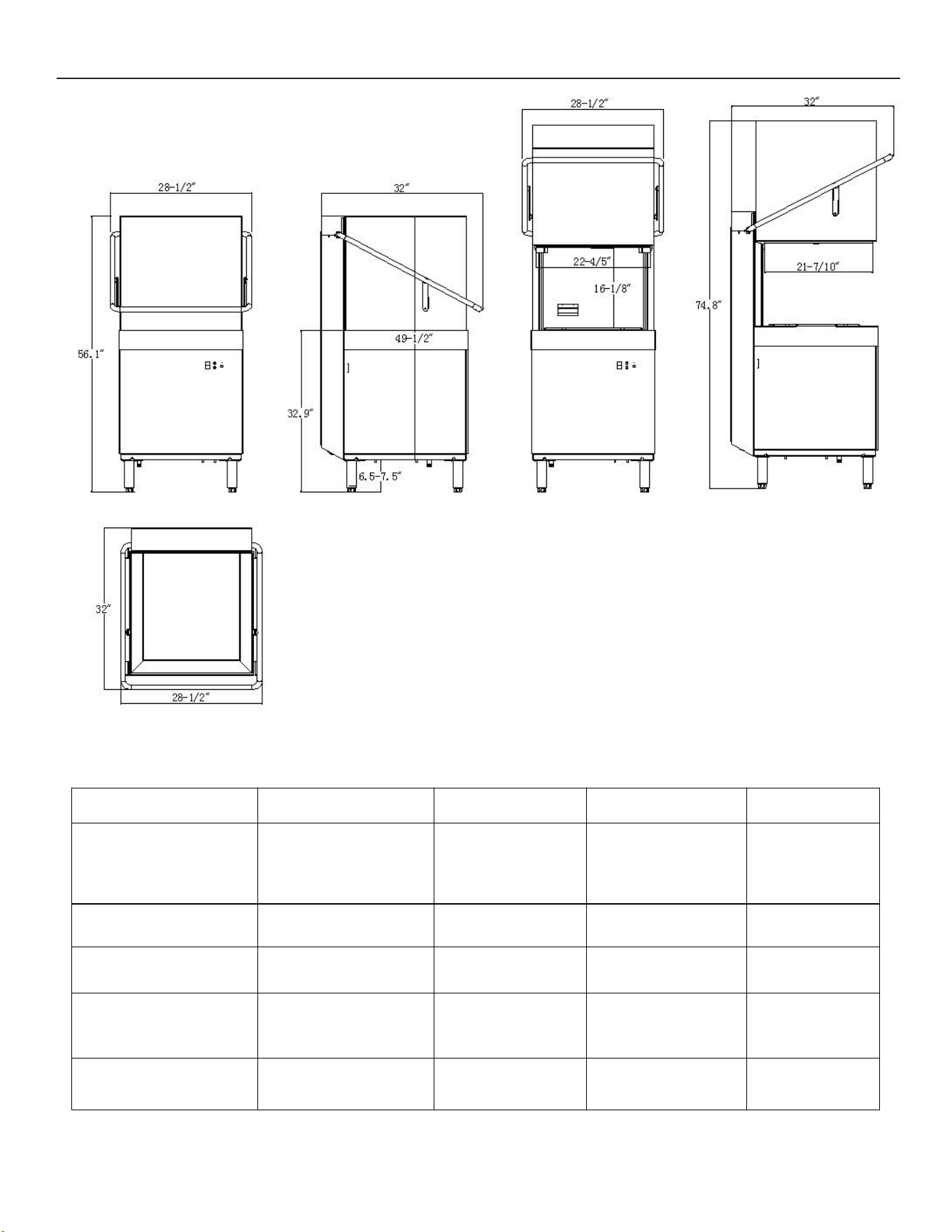
2、Product Dimension
2
/ 30
A
B
C
D
E
Total width
Total height
Height (top to
bottom)
Total depth (from
handle to back)
Height of the
storage
frame above
the ground
28-1/2"
56.1"
49-1/2"
32"
32.9"
F
G
H
I
J
Effective washing
width
Effective washing
depth
Clearance
The total depth
of the fully
opened door
Handle width
22-4/5"
21-7/10"
16-1/8"
74.8"
28-1/2"
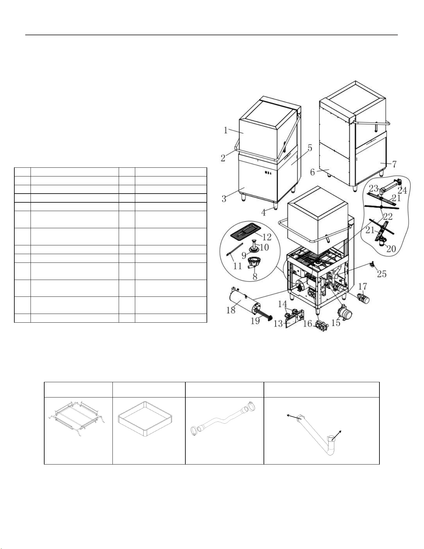
3、Names of Parts and Accessories
3
/ 30
Supplied Parts
Rack guides
Peg Rack
Drain hose
Water supply hose
L x W x H
24”x20.67”x3.15”
X1
L x W x H
19.3”x19.3”x4”
X2
62”long
0.75” inside diameter
X1
1/2 "internal thread
3/4”internal thread
62” long
X1
1
Upper cover
14
Water level switch
2
Door pull rod
15
Main wash pump
3
Front sealing plate
16
Built-in dispensor
4
Adjustable support feet
17
Rinse pump
5
Right sealing plate
18
Booster
6
Rear sealing plate
19
Rinse heating
element
7
Left sealing plate
20
Lower T-piece
connection
8
Bottom drainage flange
21
Wash arm
9
Drainage filter screen
22
Rinse arm
10
Drainage rod
23
Up T-piece
connection
11
Main wash heating
element
24
Rear T-piece
connection
12
Main washing filter
screen
25
Inlet solenoid valve
13
Control box
4、Operating Instructions(continued)
4
/ 30
4.1 NOTES ON THE DOCUMENTATION
This document contains important information for the installation and startup of the machine by
qualified personnel, as well as the information required for day-to-day operation by the operator.
▶ Keep the operating instructions and all referenced documents in a safe and accessible place.
This Installation and Operations manual is subject to change.
4.2 Layout of the documentation
Referenced documents are all instructions that describe the installation, operation, maintenance, and repair
of the device, as well as additional instructions for all accessories used.
For the operator:
- Operating instructions
For the qualified technician (available online):
- Installation instructions
- Circuit diagram
- Spare Parts Catalog
4.3 Representative convention
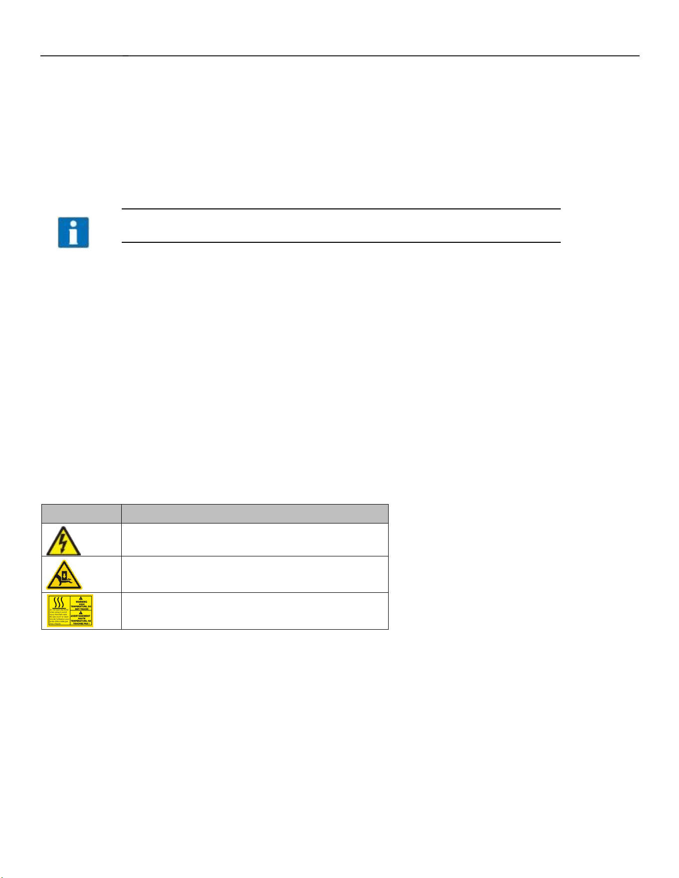
Symbols used
Symbol
Meaning
Warning of hazardous electrical voltage
Beware of pressure hand
Pay attention to high temperature to prevent
splash injury
4、Operating Instructions(continued)
5
/ 30
4.4 SAFETY INSTRUCTIONS AND REGULATIONS
4.4.1 Safety instructions and warning notices
During machine operation, observe the general safety instructions and warning notices that precede each
action.
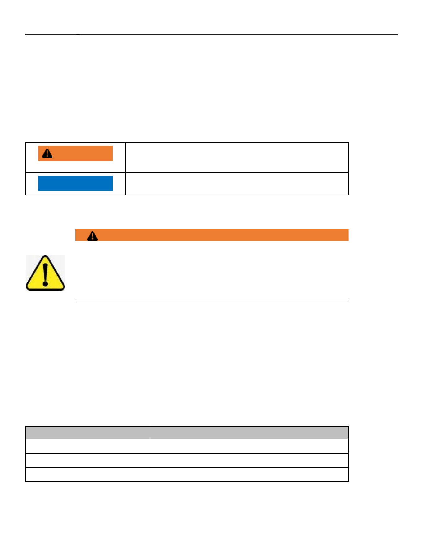
4.4.2 Hazard levels
The hazard level is part of the safety instructions and is denoted by the signal word. Potential
consequences are differentiated by the choice of signal word.
WARNING
potentially hazardous
situation: can cause
serious physical injury
NOTICE
potentially harmful situation:
can cause damage to the product or other objects
4.4.3 Layout of warning notices
Warning notices are depicted with warning symbols and signal word in the corresponding safety colors.
WARNING!
Nature and source of the hazard
Explanation on the nature and source of the hazard.
Measures for averting the hazard
Additional measures for averting the hazard, where applicable.
4.5 Basic safety instructions
4.5.1 Product safety
The machine conforms to state-of-the-art technology and the recognized safety regulations.
Nonetheless, hazards may occur.
Operate the machine only if it is in good working order and in compliance with the operating instructions.
4.5.2 Personnel qualification
Observe the regulations on occupational health and safety.
Carefully read through the operation manual before use.
Activity
Qualification/training
Installation/Setup
Qualified electrician and plumber
Work on the electrical system
Qualified electrician
Maintenance, repair
Qualified service technician

4、Operating Instructions(continued)
6
/ 30
4.5.3 Product-specific hazards
Observe the instructions on the packaging for storage, lifting or transporting.
Avoid electric shock, risk offire:
Do not allow water to flow under live components.
- Make sure the machine is correctly stored (see frost damage section2.3).
- Make sure that the machine does not overflow when being filled.
Have the machine connected to the power supply by qualified personnel.
Have all maintenance to the machine carried out by qualified personnel.
Avoid chemical burns, irritation of the skin, poisoning:
Wear protective equipment (gloves, safety goggles, protective clothing) when handling chemicals.
Use only suitable chemicals. Observe the manufacturer’s instructions.
Do not open the machine during operation, wait for the cycle to finish.
For cleaning, wear protective equipment (gloves, safety goggles, protective clothing) when touching parts
contaminated by detergent.
Avoid burns, scalds:
Do not open the machine during operation, wait for the cycle to finish. Otherwise, hot water could spray
out.
4.6 Property damage
Avoid frost damage:
Temperatures below 32°F (0°C) lead to functional damage.
Before storing below 32°F (0°C), empty residual water in hoses, tank and booster.
Prior to restart, store the machine at room temperature (min. 60°F / 15°C) for 24 hours.
4.7 PRODUCT DESCRIPTION
The machine is an item of technical equipment intended solely for commercial dish-washing.
The machine is designed solely for cleaning ware (porcelain, glass, ceramic, temperature-resistant
plastics, stainless steel or similar) from the food industry.
4.8 General
The dishwashers can be configured for both straight through or corner operation and they are shipped
from the factory in straight through configuration. Straight through machines can be easily converted to
corner operation.The dishwashers are designed to operate in high temperature sanitizing mode only
(Designated by the temperature requirements of 160°F(71℃) Wash and 180°F(82℃) Rinse. These
temperatures can be found on the label located on the lower, left part of the front panel).
The serial number can be found on the machine data label located at the bottom of the right side of the
machine.
4、Operating Instructions(continued)
7
/ 30
Detergent rinse acid pumps are built-in
The wash pump motor has thermal overload protection.
The unit, once turned on, fills the wash tank to the appropriate level and automatically stops
filling once the level is reached. A pressure transducer reads the water level in the wash tank and shuts off
the heat supply if the water level becomes too low. When the water returns to the proper level, the heating
circuit becomes operational again.
A pumped rinse system is available.
A frame mounted 12.0kW electric booster water heater is equipped on the model. The booster water heater
is designed to maintain a minimum final rinse temperature of 180°F(82℃) provided the incoming water is
at least 110°F(43℃).
High-temperature models typically require a hood or vent over the dishwasher to meet local codes.
Low-temperature chemical sanitizing machines or low usage electric heat dishwashers may not require
individual venting of the machine if the room is amply exhausted. Refer to section5.8for venting and hood
requirements. Verify with local codes for final authority.
4.9 Designation
The rating label is located on the right side of the machine. If you have any questions regarding service and
parts, use the serial number in all communications.
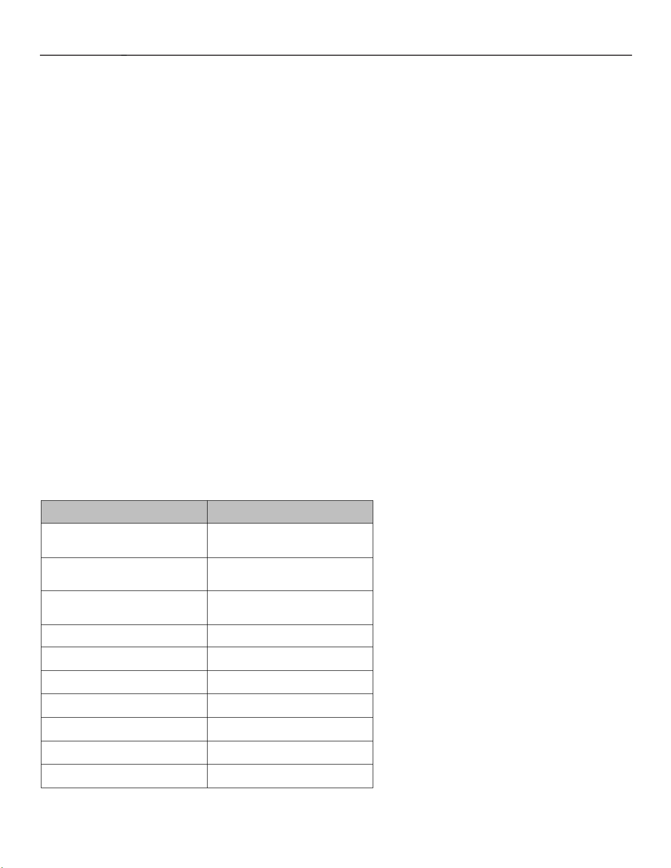
4.10 Technical specifications
Model
FCMDW0031
Dimensions (W x D)
28.54”*32”
Dimensions (H)
56.1”
Water consumption per
cycle
2.5L
Phase / Hz
1Ø /3Ø / 60Hz
Voltage
208~240V
Total connected load
36.8A
Fuse/breaker protection
40A
Tank capacity
26L
Loading height
31.5”
Machine weight
102kg
4、Operating Instructions(continued)
8
/ 30
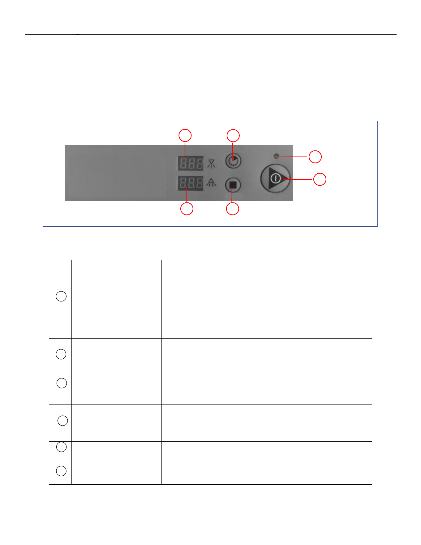
4.11 CONTROLS
1
Indicator
Blue flashing indicates adding water; No status,
indicating rinsing and heating; Red is constantly on,
indicating that the main wash is heated; Green
constantly on, indicating completion of heating and
standby mode; The combination of green and blue is
always on, indicating that the door is open; Green
flashing indicates the cleaning process; Blue flashing
indicates the rinsing process.
2
On
Pressing this button machine startup. Once machine
fills and heats ready, closing the door starts the wash
cycle. Pressing this button to confirm in menu setting.
Function
Short Pressing this button to select washing cycle,
(cycle1 70s/ cycle2 100s/cycle3 130s) Holding this button
by 7s, enters the configuration menu. Pressing this button
to adjust parameter under setting status
4
Off
Press this button to pump the water from the booster
for 30 seconds and then automatically shut down.
Pressing this button to adjust parameter under setting
status.
5
Rinse Temp
Displays rinse temperature while machine is idle and
displays remain timing in rinse cycle.
Washing Temp
Displays wash tank temperature while machine is idle
and displays remain timing in wash cycle.
6
3
1
2
4
6
3
5
4、Operating Instructions(continued)
9
/ 30
4.12 INSTALLATION
4.12.1 Personnel qualification
Installation must only be carried out by qualified personnel.
4.12.2 Special safety instructions
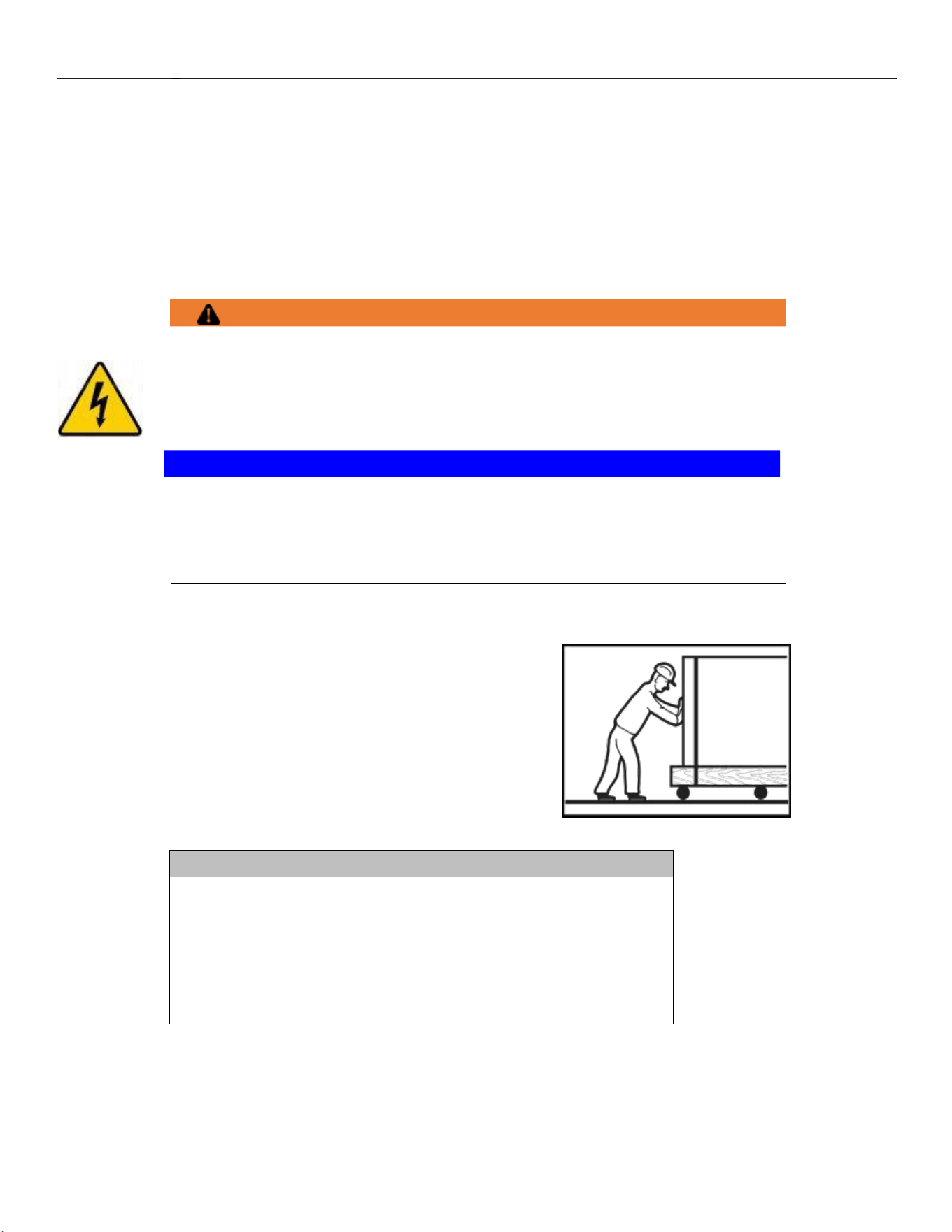
WARNING!
Risk of electric shock, fire hazard
Water flowing over live components can cause injury from electric shock or fire.
Do not allow water to flow under live components.
Make sure the machine is correctly stored.
NOTICE!
Frost damage
Temperatures below 32°F (0°C) during transport/storage cause function impairments.
Prior to installation, store machine at room temperature (min. 60°F / 15°C) for 24 hours.
4.12.3 Transporting to the installation location
Where possible transport packed on the pallet.
Use suitable transport means (forklift or hand truck, etc.).
4.12.4 Unpacking
Remove packaging materials and accessories from the machine.
Packaged in machine
• Peg rack
• Literature pack
⇨
Installation and operations manual
• Rack guide (1x)
• Water supply hose • drain hose
4、Operating Instructions(continued)
10
/ 30
Immediately after unpacking the dishwasher, check for possible shipping damage. If this machine is found to
be damaged, save packaging materials and contact the carrier within 5 days of delivery.
NOTICE!
Unpacking
Use caution when using a forklift to remove machine from pallet. Do NOT use door lift handle
to move machine, as it will cause door lift issues.
4.13 Installing the machine
Prior to installation, test the electrical supply to ensure it agrees with the specifications on the machine data
label, which is located on the lower, right side of the machine.
4.13.1 Installation Codes
Installation must be in accordance with state and local codes and the National Electrical Code ANSI/NFPA70
(latest edition). In Canada, the installation code is CSA 22.1 (latest edition).
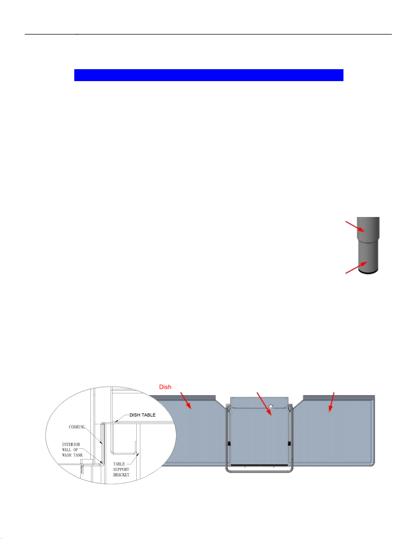
4.13.2 Attaching legs
The machine is shipped with the legs
The machine must be level to operate properly. Place the dishwasher in its operation
location. Level the machine before any connections are made.
Using a carpenter's level placed diagonally on the rack tracks,
level the machine front to back and side to side by turning the adjustable feet in or out.
4.13.3 Location
Before finalizing the location, make sure that consideration has been given for the electrical conduit,
water supply, drain connection, venting (if applicable), tabling (if needed), chemical feeder
replenishment (if applicable) and adequate clearance for opening the door.
The edge of dish table that overhangs the machine wash tank should be turned down and fitted over the top of
the dishwasher tank. Apply an NSF approved sealant between the overhang of the dish table and the inner
wall of the wash tank to prevent leakage.
Adjustable Foot
leg
Dish Table
Wash Tank
Dish Table
4、Operating Instructions(continued)
11
/ 30
For straight-through installations, 30" clearance at the front and 15" clearance at the right side by 33
- 1/8” clearance above the finished floor must be provided for service.
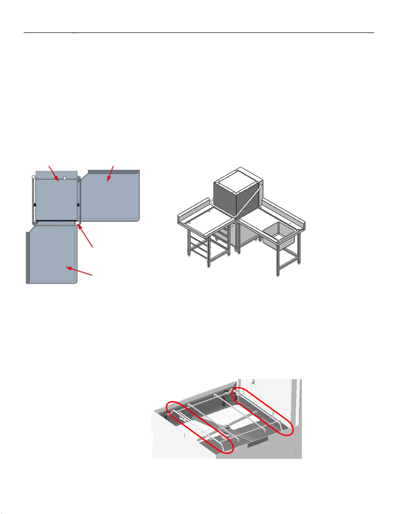
4.13.4 Corner Installation
Before placing the dishwasher in its operating location, check machine configuration. If the machine
is being installed in a corner, clearances of 30" out from the dishwasher under the left-hand tabling
by 33- 1/8" above the finished floor and 15” out from the dishwasher at the right side by 33-1/8" above
the
finished floor must be provided for servicing. For proper installation of a corner machine, the right
corner of the machine should be positioned where the two tables meet so that the gauges (if
equipped) are visible to the operator.
Wash Tank Dish Table
Right Corner
Of Machine
Dish Table
Corner Operation Shown CDL Shown
4.13.5 Rack guide installation
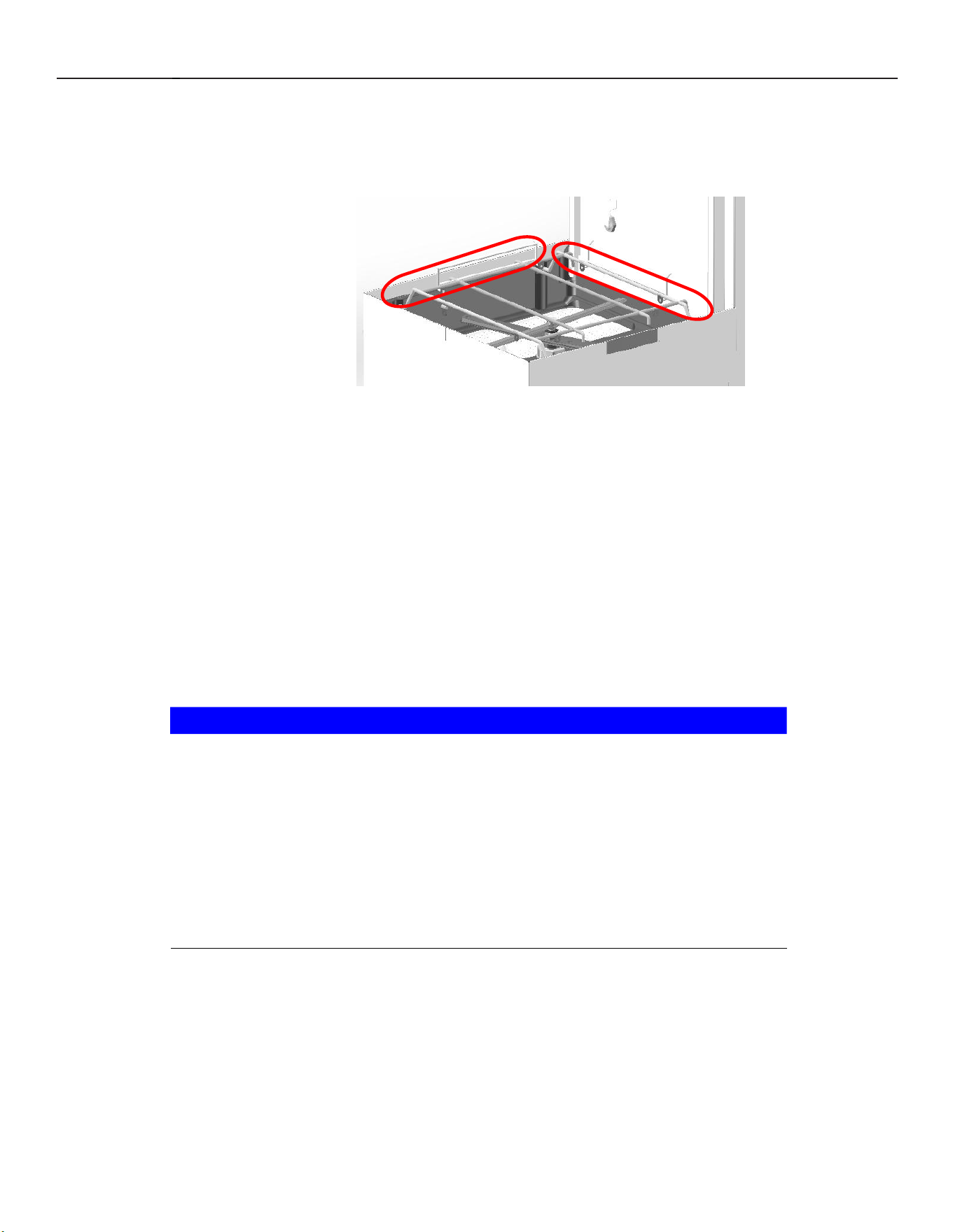
For straight-through installations,
Position rack guides on front side and the backside of the rack track aligning holes in rack guide to
spacers on rack track.
Secure using included hardware. Note: Nuts should be installed on the inside of the rack track.
c
4、Operating Instructions(continued)
12
/ 30
For corner installations,
Position rack guides on left side and the backside of the rack track aligning holes in rack guide to
spacers on rack track.
Secure using included hardware. Note: Nuts should be installed on the inside of the rack track.
4.14 Connecting the water
NOTE: The machine must be operated with potable water.
4.14.1 Water Requirements
Proper water quality can improve ware washing performance by reducing spotting, enhancing
effectiveness of labor, and extending equipment life. Water conditions vary from one location to
another. The recommended proper water treatment for effective and efficient use of this equipment will
also vary depending on the local water conditions. Ask your municipal water supplier for details about
your local water conditions prior to installation.
Recommended water hardness is 3 grains of hardness per gallon or less. Higher hardness may cause
excessive formation of lime scale. Water hardness above 3 grains per gallon requires water treatment.
Water treatment has been shown to reduce costs associated with machine cleaning, reduce deliming of the
dishwasher, and reduce detergent usage in the dishwasher.
NOTICE!
Water quality
High iron levels in the water supply can cause staining and may require an iron filter.
High chloride levels in the water supply can cause pitting and may require a chloride
removal system. Contact FORNO Service or your local water treatment professional for
proper water treatment.
Sediment may require a particulate filter. Dissolved solids may require water treatment such
as a water softener, reverse osmosis system, etc. Contact FORNO Service or your local
water treatment professional for proper water treatment.
4.14.2 Water Connection
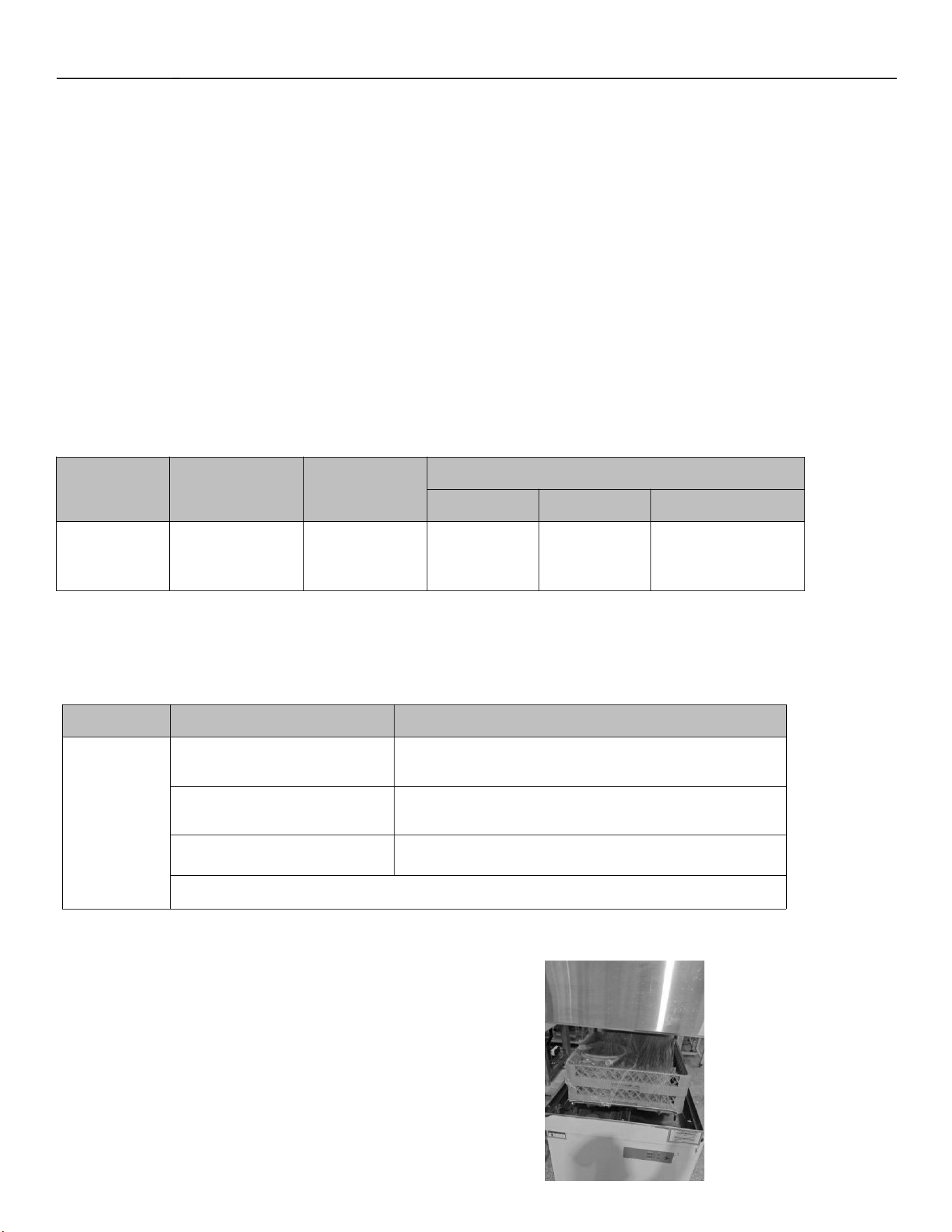
A water hammer arrestor (meeting ASSE-1010 Standard or equivalent) should be installed (supplied by
others) in the common water supply line at the service connection.
The plumber connecting this machine is responsible for making certain that waterlines are
4、Operating Instructions(continued)
13
/ 30
THOROUGHLY FLUSHED OUT BEFORE connecting to the dishwasher. This "flush-out" is necessary to
remove all foreign matter, such as chips (resulting from cutting or threading of pipes), pipe joint
compound from the lines; or, if soldered fittings are used, bits of solder or cuttings from the tubing.
Debris, if not removed, may lodge in the dishwasher's plumbing components and render them
inoperative. Solenoid valves fouled by foreign matter and any expenses resulting from this fouling are NOT
the responsibility of the manufacturer and associated repair costs are not covered under warranty.
A manual shutoff valve (not supplied) should be installed upstream of the fill hose to accommodate
servicing the machine. It is recommended that a line strainer (80 mesh) (not supplied) be installed in the
supply line between the manual shutoff valve (not supplied) and the connection point on the machine. Make
plumbing connections with ½” minimum copper piping OD (¾” recommended),with a ¾” male
garden hose fitting (not supplied).
Connect to hot water
A water supply hose is provided.
Temperature:
Model
Sanitizing
Mode
Connection
Water Supply
Minimum
Maximum
Recommended
FCMDW
0031
High
temperature
Sanitizing
Hot Water
110°F
(43°C)
N/A
140°F (60°C)
Water hardness: max. 3 grains
Flowing pressure:
Model
Flowing Pressure
Note
FCMD
W0031
28 psi – 58 psi (2 bar – 4
bar)
Recommended
> 65 psi (4.5 bar)
Provide pressure regulating valve (not
supplied)
< 28 psi (2 bar)
Improper machine operation may result
Pumped rinse system; Water pressure gauge is not required
The supply hose, 62 ” long, 3/4” internal thread and 1/2”internal thread ,
is provided with the machine .
4、Operating Instructions(continued)
14
/ 30
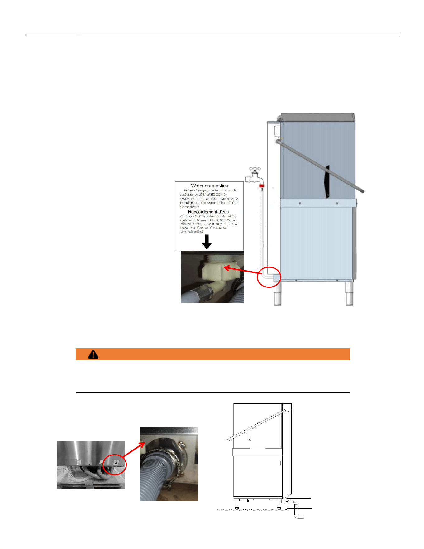
Find the water connection label at the bottom of rare panel and connect the end of water supply hose 3/4”
thread to machine, and connect the end of the water supply hose (1/2” garden
hose thread) to the building shut off valve.
Note that:
4.15 Connecting the drain
A drain hose,0.75” inside diameter and 62” long, is provided with the machine and is shipped
attached and coiled up inside the machine
.
WARNING!
Plumbing connections
Plumbing connections must comply with applicable sanitary, safety, and plumbing codes.
Outlet
Drain
- Use care not to kink or cut the water supply hose.
- Any required extension must be made using a
suitable pressure hose.
- A backflow prevention device that confomms
toANSI/ASSE1022, Or ANSI/ASSE 1024, Or ANS1032
must be installed at the water inlet of thisdishwasher.
(provided by the customer)
4、Operating Instructions(continued)
15
/ 30
Note that:
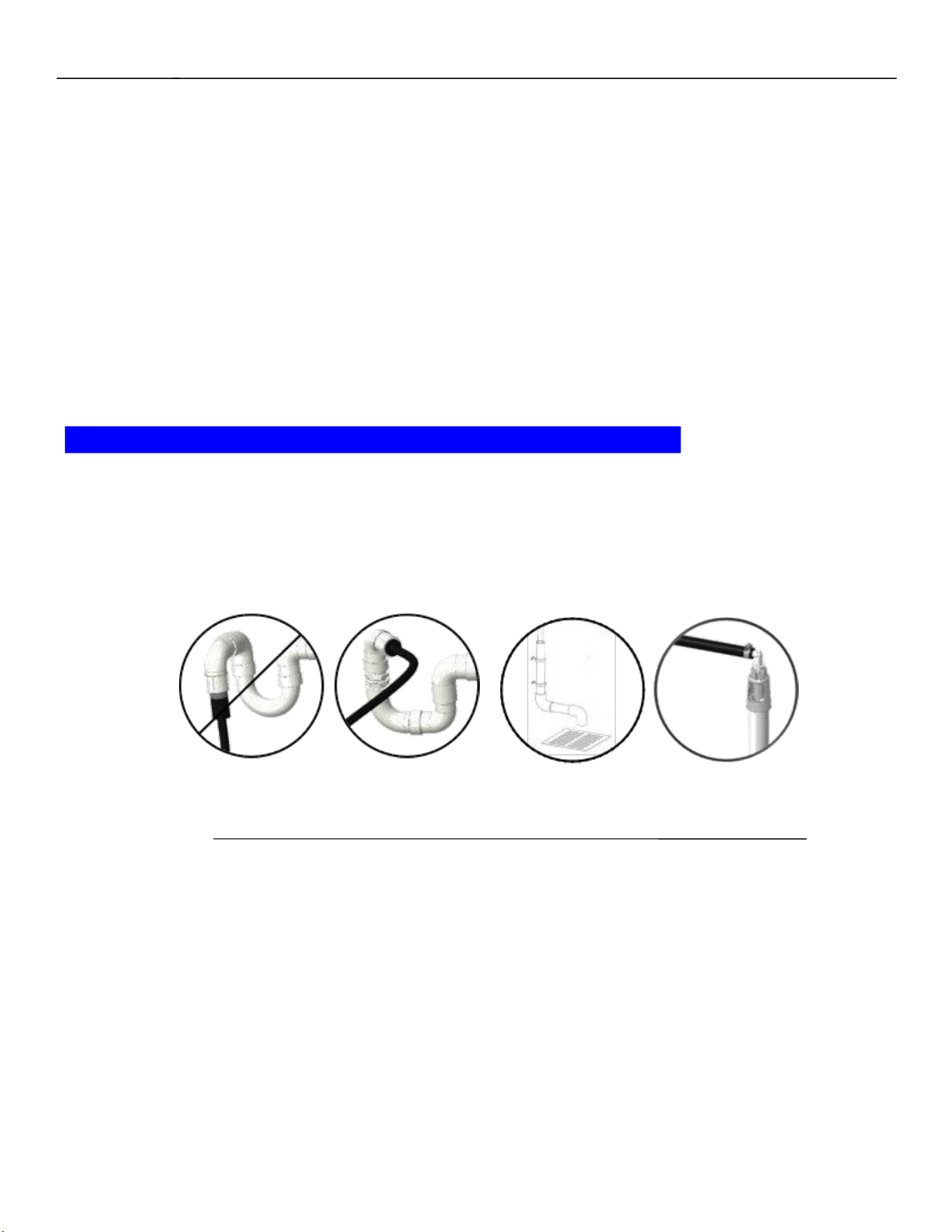
-
The connection between machine and building drain must not
exceed a maximum height of 5.1” above
finished floor.
- Drain must have a minimum flow capacity of 5 gallons per
minute.
-
If a grease trap is required by code, it should have a minimum flow capacity of 15 gallons per
minute.
-
If machine is located directly above a floor drain, a knockout in the bottom of the dish machine is
provided for the drain hose.
- Use care not to kink the drain hos
NOTICE!
Drain connection
An improper drain connection or a kinked hose could result in reduced machine
performance and errors. An air gap connection is the preferred connection method.
Incorrect
Acceptable
Preferred
(Meets Code Requirements)
4、Operating Instructions(continued)
16
/ 30
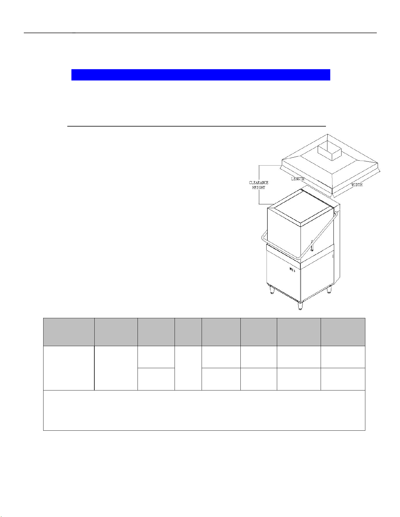
4.16 Venting Requirements
NOTICE!
Exhaust Hood
Any commercial exhaust hood must be installed according to all local and national codes and
the manufacturer’s installation instructions, if applicable.
4.16.1 Rate of Exhaust Flow Calculations
Based on the 2018 International Mechanical Code.
The minimum net airflow for Type II hoods used for
dishwashing appliances shall be 100 cfm per linear foot of hood
length. The net quantity of exhaust air shall be
calculated by subtracting any airflow supplied directly to a hood
cavity from the total exhaust flow rate of a hood.
According to 507.3 of the 2018 IMC, Type II hoods are not required
where the heat and moisture load is incorporated
into the HVAC system design. See Table A for heat
dissipation or heat gain to space.
Table A: HEAT DISSIPATION
Model
Sanitizing
Mode
Voltage
Phase
Electric
Heat
Electric
Booster
Latent
Heat
(BTU/Hr)
Sensible
Heat
(BTU/Hr)
FCMDW0031
High
Temperature
208V
1Ø /3Ø
X
X
16,100
6900
240V
X
X
20400
8700
Assumptions:
1. Machines operate 70% of each hour while in use.
2. Values shown are heat that enters room.
3. 70% of heat output is latent, 30% is sensible.
4、Operating Instructions(continued)
17
/ 30
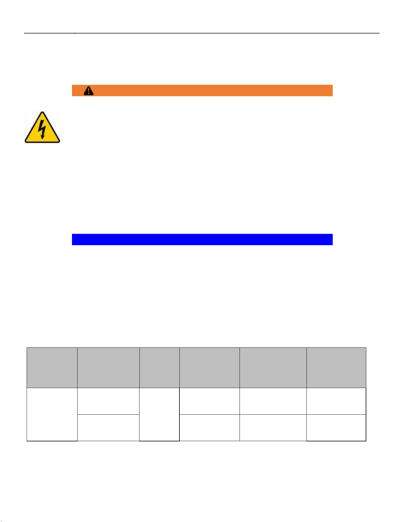
4.17 Connecting to the power supply
WARNING!
Risk of electric shock
Electrical and grounding connections must comply with the applicable portions of the
National Electrical Code, NFPA 70 (latest edition) and/or other local electrical codes.
Disconnect the electrical power to the machine and follow lockout/tagout
procedures.
4.17.1 Electrical Data
Refer to the sizing diagram located inside the front trim panel and to the data label on the lower, right side of
the machine for service size requirements when connecting the dishwasher. Also, refer to the Electrical
Data, shown below.
NOTICE!
Supply connections
For supply connections, use copper wire only rated at 194°F (90°C)minimum.
The dish machine is not provided with internal GFCI protection.
A fused disconnect switch or circuit breaker (customer supplied) must be installed in the
electrical service line supplying this dishwasher and should meet the
requirements of your local electrical code.
ELECTRICAL DATA
Model
Volts/Hertz
Phase
Rated
Ampacity
Minimum
Supply Circuit
Conductor
Ampacity
Maximum
Protective
Device
Ampacity
FCMDW0031
208V/60Hz
1Ø /3Ø
36.8
40
40
240V/60Hz
36.8
40
40
Compiled in accordance with the National Electrical Code NFPA-70 (latest addition).
4、Operating Instructions(continued)
18
/ 30
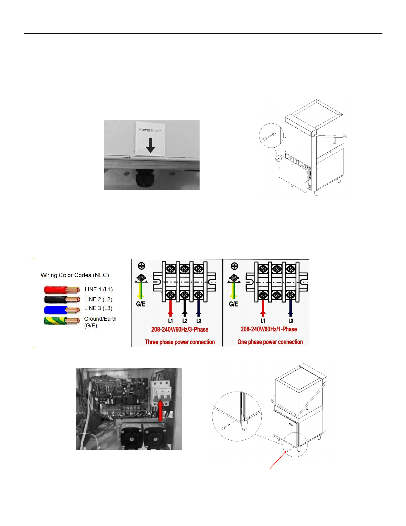
4.17.2 Electrical Connection
Remove the rare panel by removing the eight screws at the panel.
Make electrical connections according to the wiring diagram supplied with the machine and the
applicable electrical code. Select the proper connection configuration based on the available power
supply: single-phase or three-phase, as shown in the wiring diagram. Secure all wires to the machine
service connection.
Recommended conductor size is 9 AWG. Keep excess wire in the base of the unit to a minimum.
A cable support and hole for a strain relief are supplied to facilitate wire routing.
Remove the screws on the front panel, locate the air circuit breaker and
open it
4.18 CHEMICAL SUPPLY SET UP
4.18.1 Personnel qualification
Setup must only be carried out by qualified personnel (see section)
40.0A
40.0A
4、Operating Instructions(continued)
19
/ 30
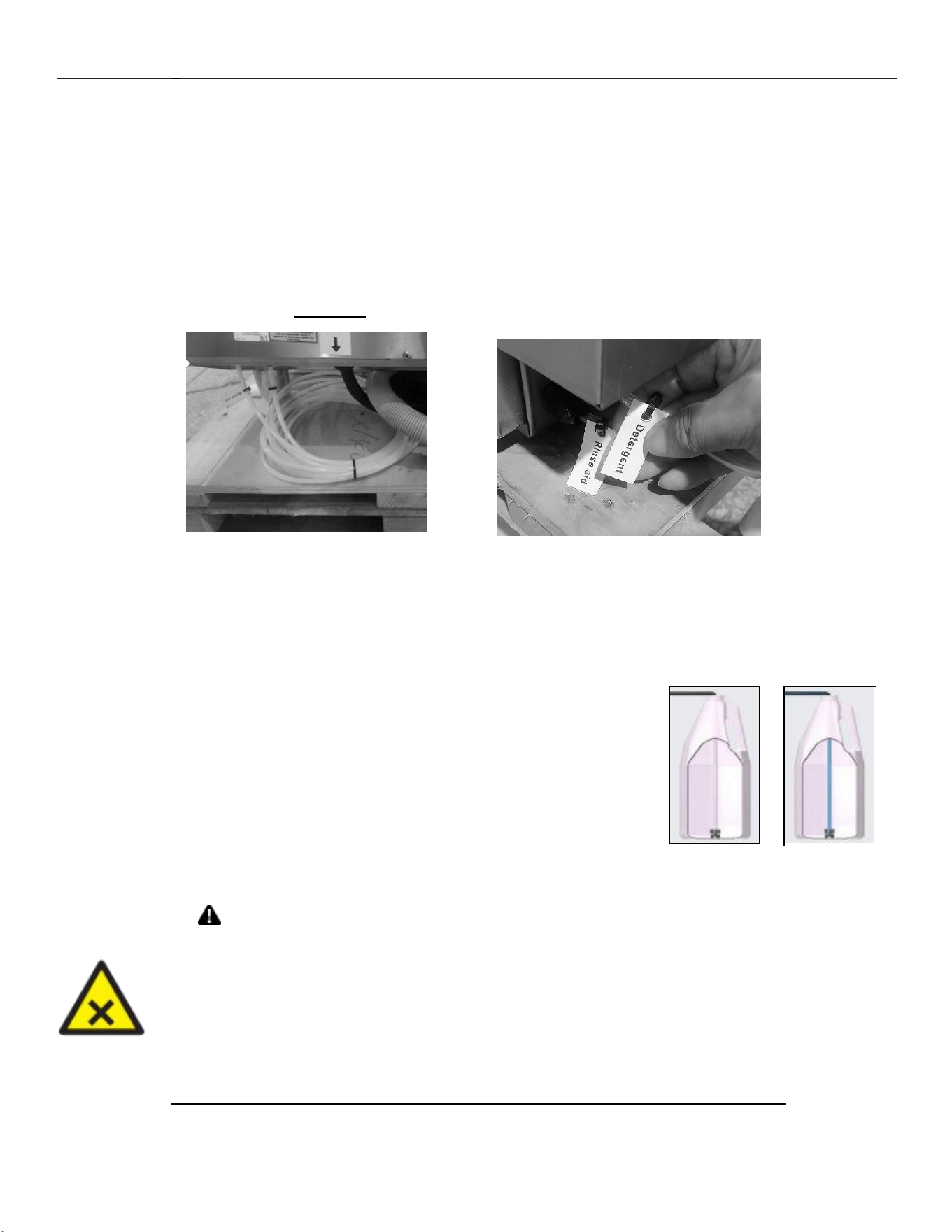
4.18.2 Checking the chemical supply tubing
checking the chemical supply tubing:
The chemical tubing with 94.85” long assembled in
the base of the machine.
Check chemical labels:
⇨ The clear tubing – Detergent
⇨ The clear tubing – Rinse Aid
r
4.18.3 Setup of external chemical bottles/buckets
Preparing the detergent, rinse aid
Suction height of detergent, rinse aid pumps: max. 5 ft
Standard suction tubes
Standard suction tubes
Place clear suction tubing marked for detergent at the bottom of the external
detergent bottle/bucket.
Place clear suction tubing marked for rinse aid at the bottom of the external
rinse aid bottle/bucket.
4.18.4 Filling chemical tubing
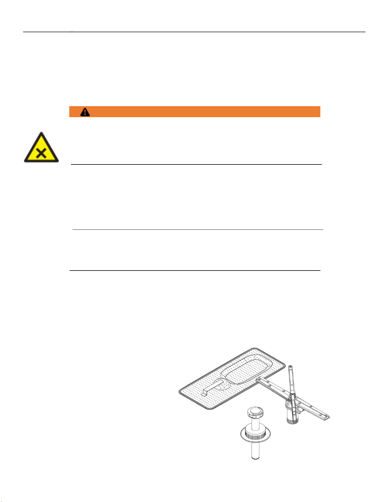
WARNING!
Chemical burns, irritation of the skin
Filling the chemical tubing with detergent, rinse aid for the first time incorrectly can
cause serious injury.
Wear protective equipment (gloves, safety goggles, protective clothing) when handling
chemicals.
Observe the manufacturer’s application and safety instructions.
4、Operating Instructions(continued)
20
/ 30
4.19 OPERATION
4.19.1 Personnel qualification
The machine must be operated by qualified personnel.
4.19.2 Special safety instructions
WARNING!
Chemical burns, irritation of the skin, scalding
If the door is opened during operation, wash water can spray out and cause injury.
Do not open the door during operation, wait for the cycle to finish.
4.19.3 Notes for optimal washing result
The rinse result is significantly affected by the water quality. If the mineral content is high, the minerals
dissolved become visible on the glasses in the form of spots and streaks during the drying process.
Recommended water hardness is 3 grains of hardness per gallon or less. Higher hardness
may cause excessive formation of lime scale. Water hardness above 3 grains per gallon
requires water treatment.
If you have any questions, please contact your authorized FORNO service partner.
4.19.4 Preparation for washing
Preparing the machine
Check correct position of drainage filter screen and main washing filter screen and proper installation of
upper and lower wash/rinse arms.
Open building water shut-off valve.
4、Operating Instructions(continued)
21
/ 30
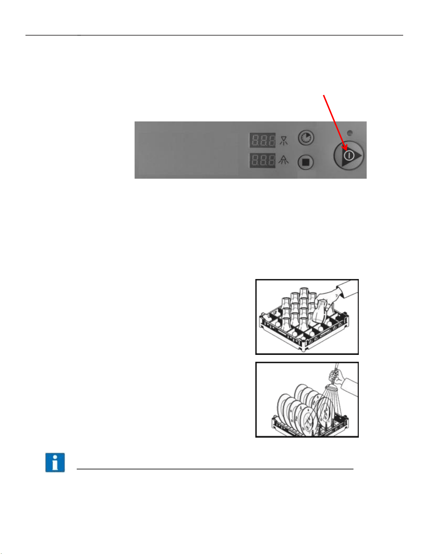
Turn on main switch or breaker.
Check level of detergent and rinse aid in containers
Close door.
Press the On
⇨
During the filling and heating processes, the indicator lighting flashes.
⇨ To achieve the best washing effect, that is, when the temperature reaches and The green light
is on, to operation.
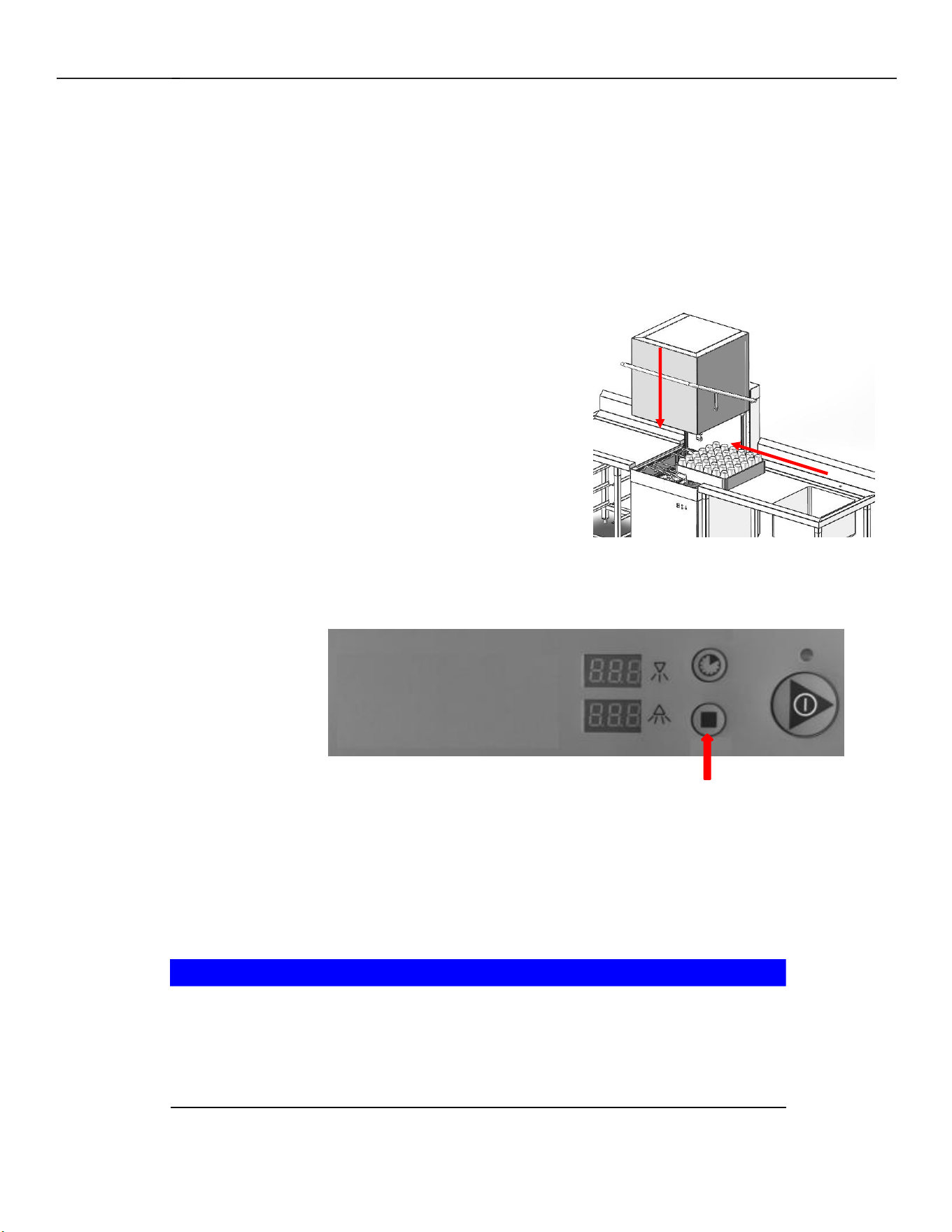
4.19.5 Preparing the ware for washing
Remove heavy food residue.
Load ware into rack.
Rinse off ware.
Never use steel wool on ware to be loaded into the dish machine.
4、Operating Instructions(continued)
22
/ 30
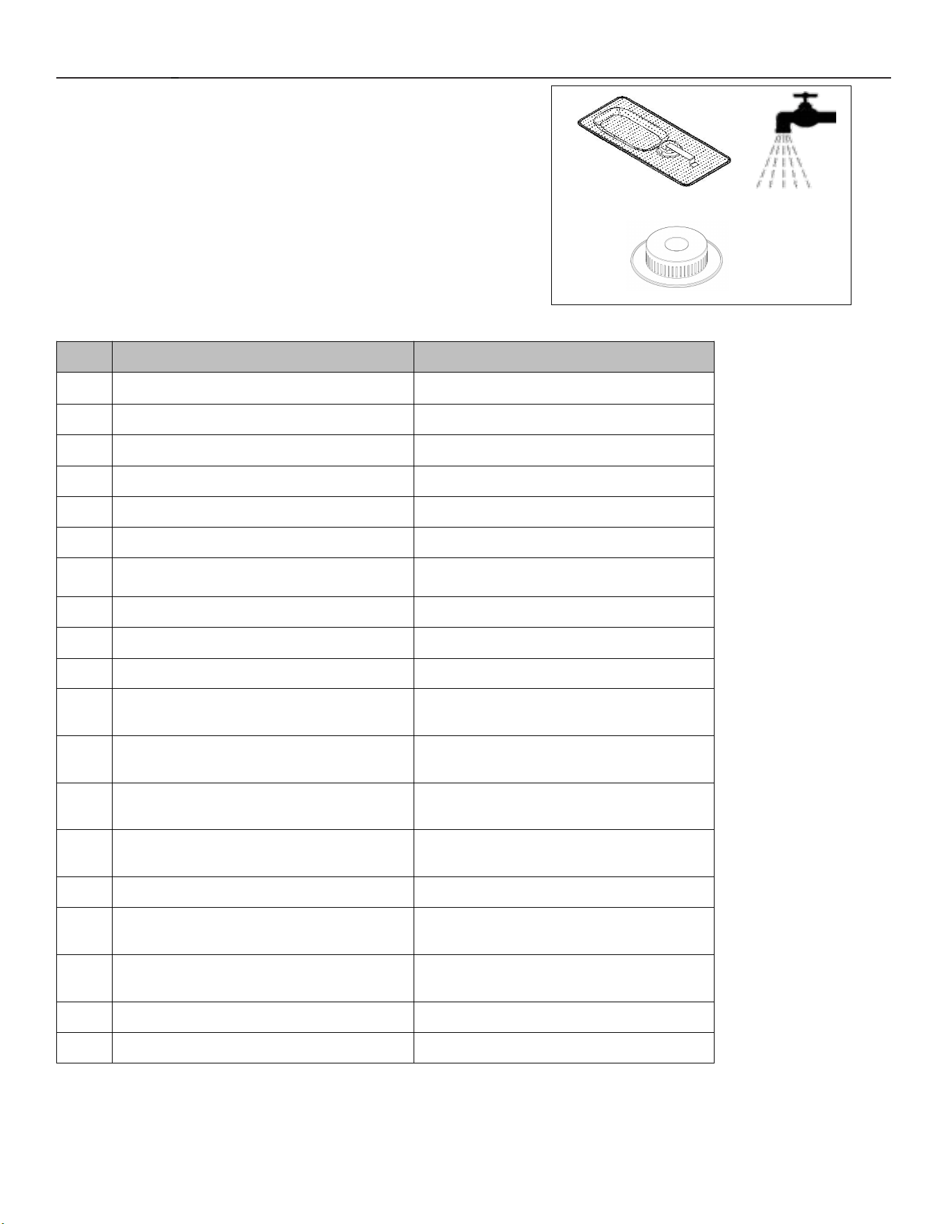
4.20 Washing
Open door.
Slide rack into the machine and close the door. The wash cycle will
start automatically.
⇨ While the washing cycle is running, the indicator LED shining
base on the washing process, As soon as the indicator LED turn
off, the washing cycles is completed.
Open the door and remove the rack.
Allow the ware enough time to dry.
4.21 Switch off machine
Press the power off button
Remove any heavy food residues.
Drain the wash tank by pulling out the rod
Turnoff main switch or breaker.
Close building water shut-off valve.
4.22 Daily cleaning or after each meal period
NOTICE!
Property damage
The use of unsuitable agents can cause corrosion damage.
Do not use any bleach, acids, or metal-containing additives to clean the machine.
Do not use metal brushes.
4、Operating Instructions(continued)
23
/ 30
4.23 SETTINGS
4.23.1 Overview of operator menu
The temperature display will have a 37-41
°
F
(
3-5
℃ )
error, which is within the normal range.
Some codes are not displayed in this table and are not applicable to this product model.
Consumers can ignore them.
Item
Menu Function
Setting (default)
d1
Cycle 1 Wash time
55 seconds
d2
Rinse start waiting time
3 seconds
d3
Rinse time
12 seconds
d4
Rinse Aid feeding time
8 seconds (should less than d3)
d5
Detergent feeding time
5 seconds (should less than d1)
d6
Maximum duration for wash tank fill
10 minutes
d8
Cycle 2 Wash time
85 seconds
d9
Cycle 3 Wash time
115 seconds
C1
Wash tank heating off temperature
161°F(72℃)
C2
Wash tank heating on temperature
156°F(69℃)
C3
Rinse booster heating off
temperature
181°F
(
83
℃)
C4
Rinse booster heating on
temperature
176°F(80℃)
CA
Detergent concentration
70% of detergent pump output
voltage
CB
Rinse aid concentration
70% of rinse aid pump output
voltage
CD
Fill after machine startup
2 seconds
CE
Detergent feeding time for 1
st
wash
cycle
3 seconds
CF
Rinse aid feeding time for 1
st
wash
cycle
3 seconds
A7
Booster drain time
30 seconds
L6
Celsius/Hua Celsius
1: Hua Celsius degree
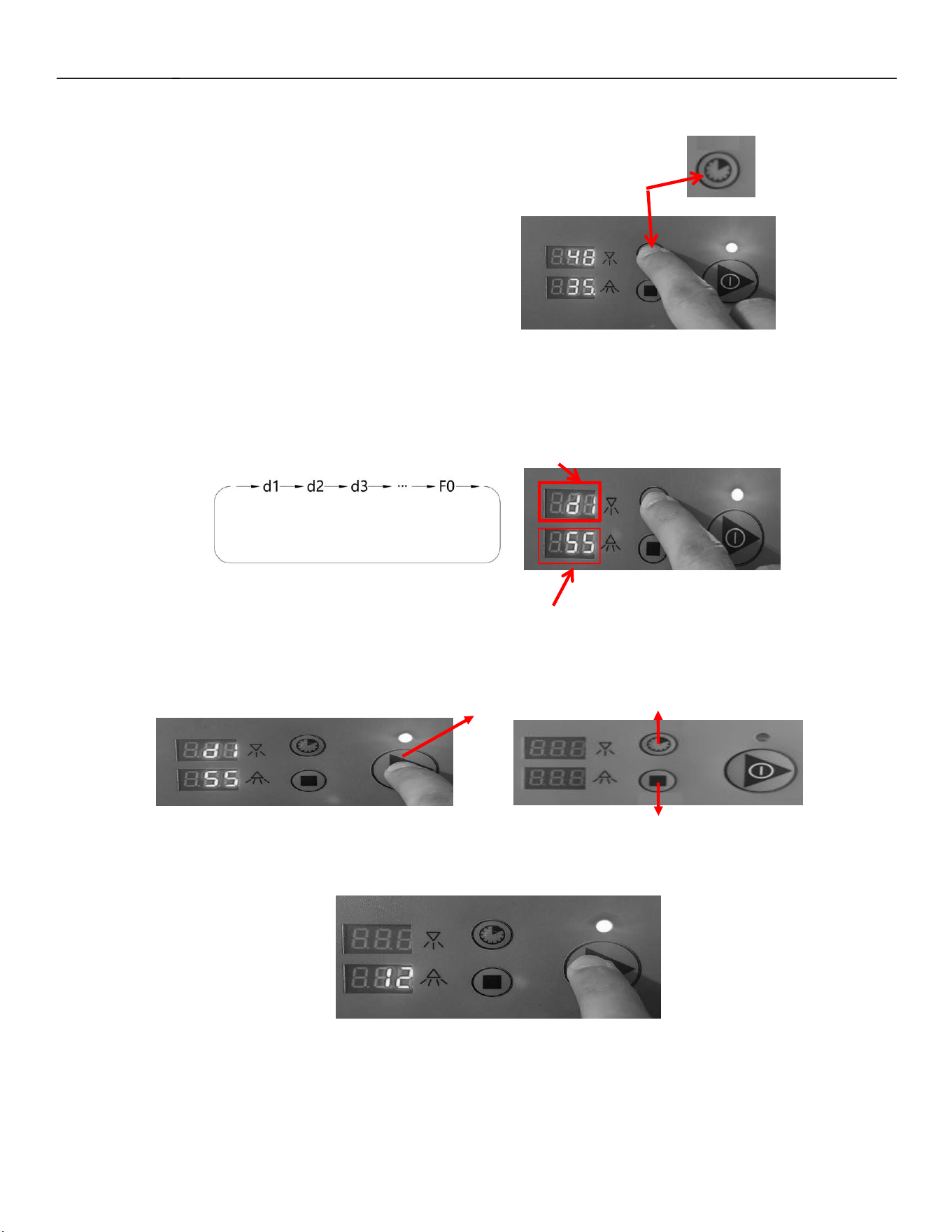
Open the door, remove main washing filter
screen and drainage filter screen. Rinse
under running water. Make sure that food.
debris does not enter pump intake when the
pump strainer is removed.
4、Operating Instructions(continued)
24
/ 30
4.23.2 Opening the operator menu
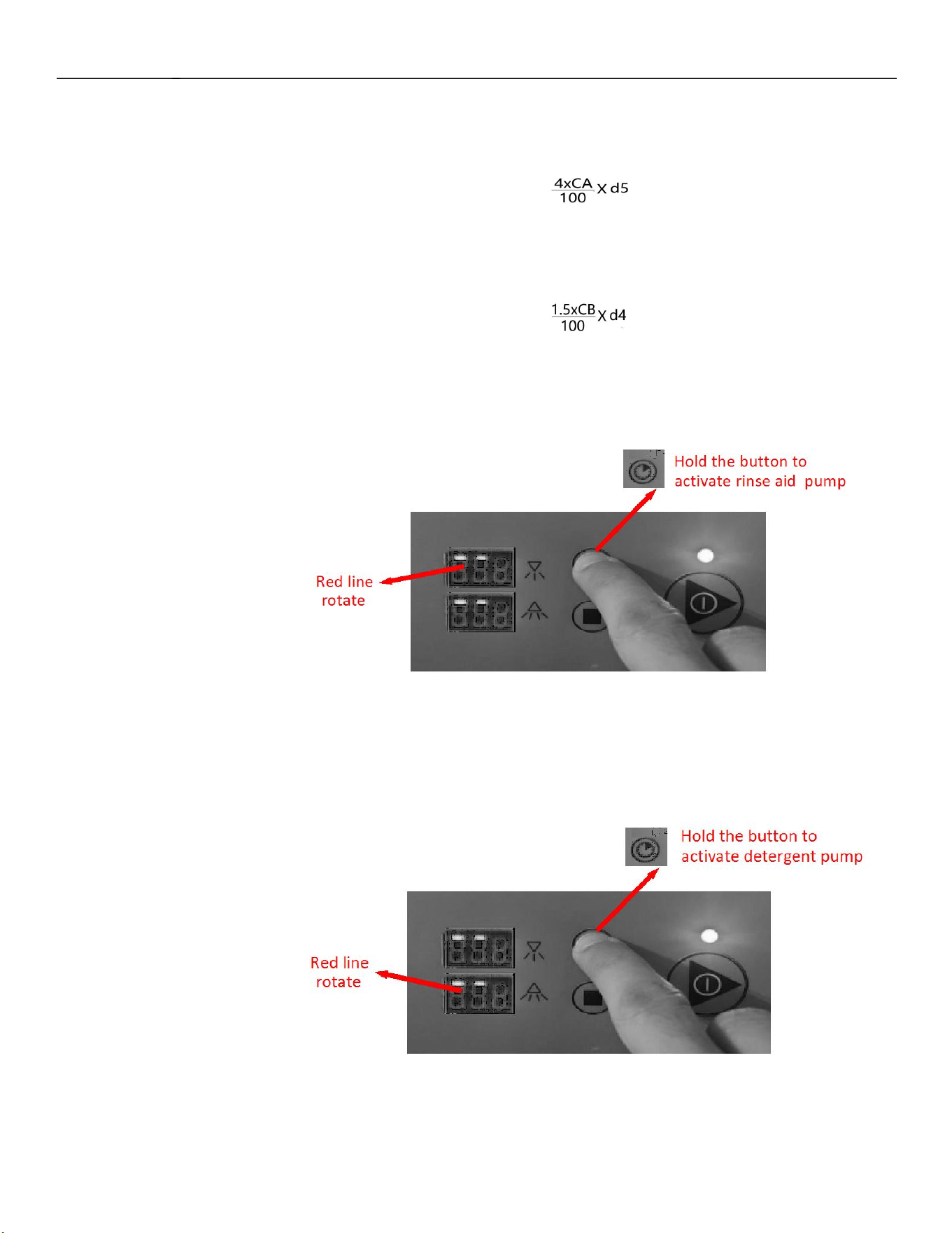
Note: Machine must be in ready (idle) state.
Press the Menu button by 7 seconds to access operator program settings.
⇨ The menu opens, temperature display will turn to item and parameter
⇨ The upper display will show the first item “d1”,and lowerdisplay will show parameter
To scroll from one item to the next, press the menu button. After the last item, the sequence will return
to the first item.
Short press Confirm Button to adjust the parameter
Decrease
To save and exit the operator menu at anytime, press Confirm Button for 3 seconds.
Increase
Short press
Parameter
Item
4、Operating Instructions(continued)
25
/ 30
4.24 Detergent and Rinse Aid Dispensing
4.24.1 Setting detergent dispensing
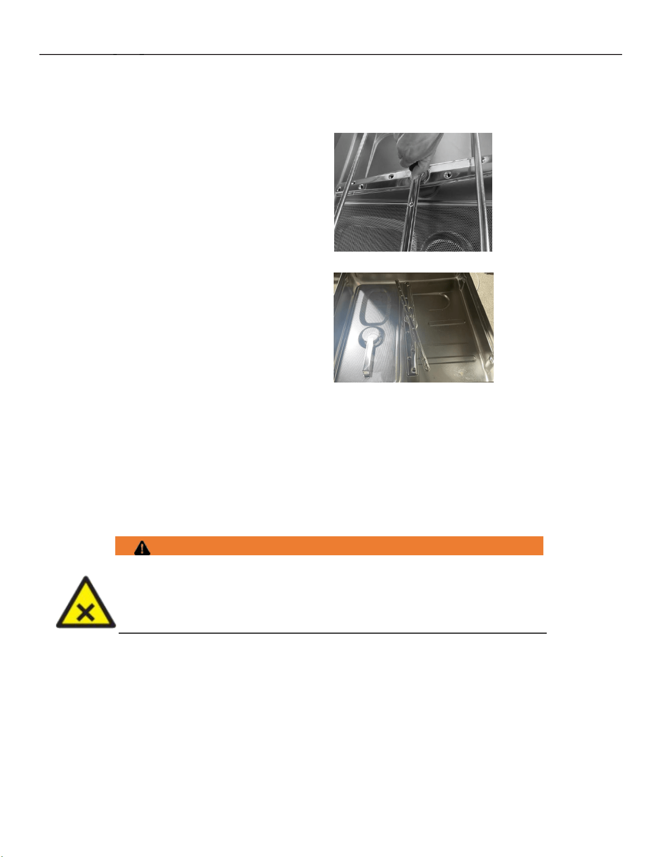
Flow speed for detergent pump is 4ml/second, formula will be
For example CA=60, d5=3 each wash cycle dispensing 7.2ml
To adjust dosage, just increase or decrease CA Parameter
4.24.2 Setting rinse aid dispensing
Flow speed for rinse aid pump is 1.5ml/second, formula will be
For example CB=60, d4=8 each resin cycle dispensing 7.2ml
To adjust dosage,just increase or decrease CB parameter
4.24.3 Priming detergent and rinse aid dispensing pump
Turn on main switch or breaker, machine on switch off state
Verify the detergent or rinse aid is moving from the
detergent/resin aid bottle or container to the machine.
Multiple operations may be required until the pipeline is filled with medication .
5、Cleaning and Maintenance
26
/ 30
5.1 Weekly cleaning
5.2 Removing hard water deposits (Deliming)
The dishwasher should be delimed on a regular basis as required. How often depends on the mineral
content of the water. Deliming should be done when you can see clear signs of lime deposits (a white
chalky substance) on the inside walls, on the wash and rinse arms or tank heater. Inspect the machine
interior for lime deposits. When deliming is necessary, a deliming agent (such as Lime-A-Way® or LSR®)
should be used for best results.
Chemical mixing
Deliming solution must not come in contact with bleach or rinse solution containing bleach.
Mixing may cause hazardous gas to form. This entire procedure must be
followed step-by-step for safe and satisfactory results.
WARNING!
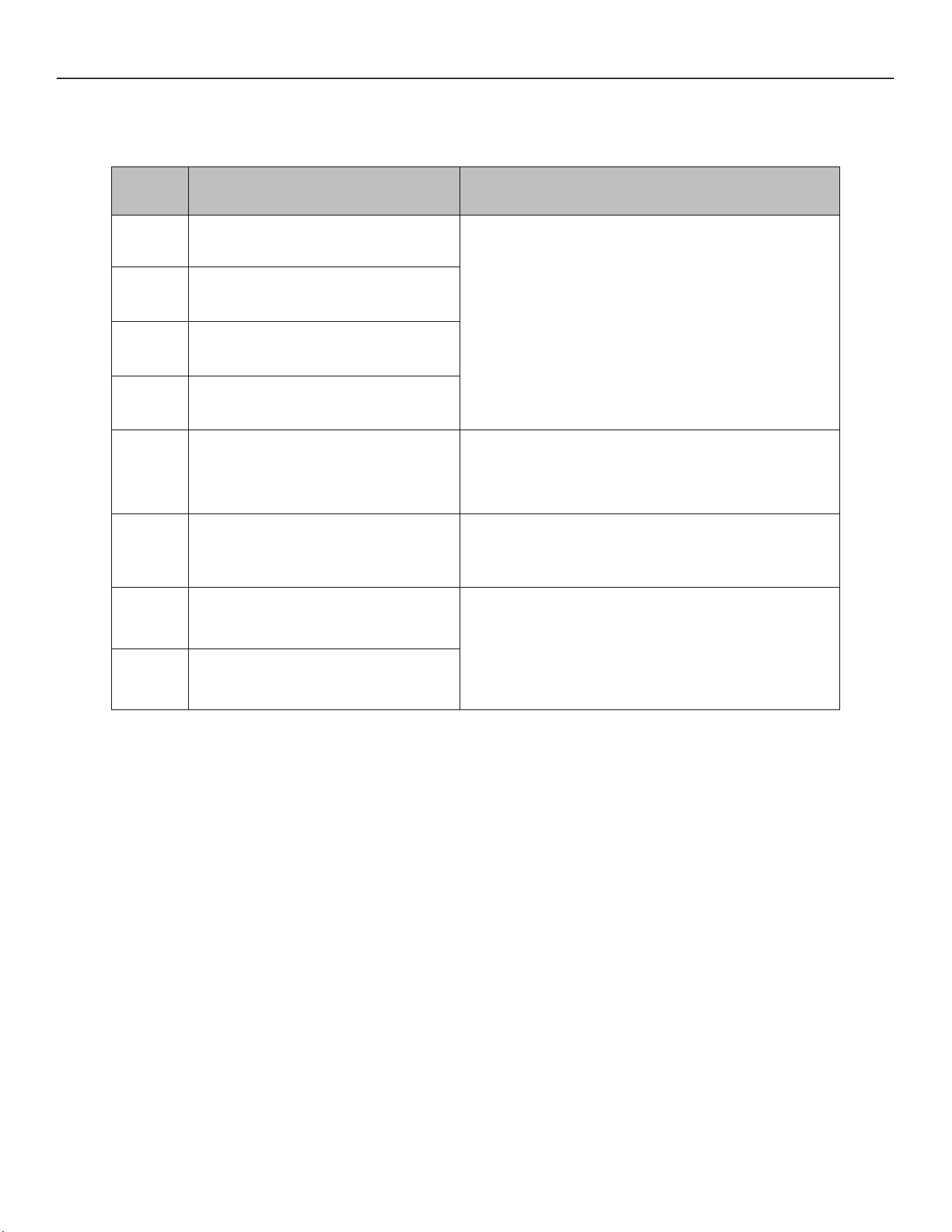
-Disassembly the lower wash and rinse arm by
anticlockwise Remove and clean wash and rinse
arm.Repeat for upper arm Replace all parts.
-The inner cavity of the sink is flushed with
water pressure ranging from 1.5 bar to 3.0 bar.
6、Troubleshooting
27
/ 30
6.1 Information
The error code is shown in the bottom display (see table).
Error
code
Symptom
Possible Solution*
E1
Rinse Temperature Sensor
Open Circuit
1. Check whether the line loose or disconnected
2. Check sensor burn out or damage
3. If error continues to display – contact qualified service
person
E2
Rinse Temperature Sensor
Short Circuit
E3
Wash Temperature Sensor Open
Circuit
E4
Wash Temperature Sensor Short
Circuit
E7
Wash Tank Fill Time Exceeded
1. Switch off the machine, pull out the rod and drain, then
restart
2. Check whether the water level pressure sensor fault
3. If error continues to display – contact qualified service
person
E9
Overheat fault
1. Check overheat switch open circuit or short circuit.
2. If error continues to display – contact qualified service
person
EC
Wash heater fault
1. Verify whether controller or contactor fault
2. Replace heater
3. If error continues to display – contact qualified
service person
ED
Rinse heater fault
6、Troubleshooting(continued)
28
/ 30
6.2 TROUBLESHOOTING GUIDE
6.2.1 Poor wash results
Fault Type
Possible Cause
Remedy
Ware
not clean
Was harm hard to turn
(must rotate easily by hand).
• Remove wash arms and clean
them thoroughly.
• Also check that water manifold
from machine to wash arm is
clear.
Wash arm nozzles are
clogged (visual check).
• Remove wash arm and rinse
wash arm thoroughly until all
soiling is removed.
Rinse nozzles clogged
(usually by lime deposit).
•
Remove rinse arms and delime
them in separate container.
• Check building softening system
for function.
• Delime machine if needed.
Detergent concentration is too low or too
high.
Check detergent concentration setting
(See operating instructions.
Tank strainers clogged.
Remove strainer pan(s), empty and
clean strainer(s).
Pump strainer clogged.
Remove, empty and clean strainer.
Wrong program selected for heavily
soiled wash ware.
Extend the wash program for longer wash
cycle.
Ware or
glasses
dry poorly
Rinse aid concentration too low.
Increase concentration
(see operating instructions)
Wash ware still greasy.
Detergent concentration too low:
increase (see operation instructions).
Check if detergent is appropriate. If
not, choose a stronger one.
Drain contaminated water and refill
machine. Ensure better pre-scrapping of
the wash ware.
Wash ware left in machine too long
after the end of wash cycle.
Remove wash ware as soon as
cycle is completed when ware is at
its highest temperature to enable
better drying.
Streaks
and spots
on
ware or
glasses
Rinse aid concentration too
high (stripe or bubble
formation)
Reduce rinse aid
concentration (see
operating instructions)
Hard water or high mineral content.
Check water quality.
Improper rinse aid
Consult your local chemical provider
Inadequate rinse aid dispensing causes
stains.
Increase rinse aid
concentration (see operating
instructions)
For troubleshooting videos, pls. scan the QR code below.

Warranty
What this limited warranty covers:
• This limited warranty provided by Forno Appliances applies
exclusively to the original Forno appliance
(“Product”) sold to the original purchaser (“Purchaser”) by an
authorized Forno dealer, distributor, or retailer, and installed
in the United States or Canada. The Product must remain
within the country of original purchase.
• This warranty is valid for a period of one (1) year from the
date of original retail purchase and covers parts and labor.
• The warranty period may vary depending on the retailer or
authorized dealer from whom the product was purchased.
Please refer to your retailer's warranty terms or proof of
purchase to confirm the applicable warranty coverage and
duration for your product.
• This warranty is strictly limited to commercial use. Any
residential use of the Product will void this warranty.
• Forno Appliances will repair or replace, at its discretion, any
component or part that proves to be defective due to
manufacturing defects in materials or workmanship under
normal commercial use during the warranty period. Repair or
replacement will be performed by a Forno Authorized Service
provider during normal working hours.
• This warranty does not cover installation, misuse, abuse,
improper maintenance, or normal wear and tear. The
Purchaser is responsible for ensuring the Product is
reasonably accessible for service.
• Warranty coverage is non-transferable. In the event of
replacement of parts or the entire Product, the replacement
will assume the remaining warranty period from the original
purchase date. The warranty period will not be extended.
Important
Retain proof of or
iginal purchase
to
establish the warranty period.
Forno’s liability on any claim of any kind, with respect to the
goods and/or services provided, shall in no event exceed the
value of the product, service, or part thereof which has given rise
to the claim.
30-Day Cosmetic Warranty
The Purchaser must inspect the Product at the time of delivery.
Forno warrants that the Product is free from manufacturing-
related cosmetic defects in materials and workmanship for a
period of thirty (30) days from the date of original retail
purchase.This coverage includes:
• Paint blemishes
• Visible finish defects
Cosmetic warranty does NOT cover:
• Damage resulting from improper transportation, handling, or
installation (including dents, warping, deformation, or
damaged components, cracked or damaged glass
components)
• Minor color variations in painted or enameled parts
• Differences caused by lighting conditions, installation
location, or similar factors
• Stains, corrosion, or discoloration caused by external
substances or environmental conditions
• Labor costs
• Display models, floor models, B-stock, open-box, “as-is”
products, or demo units
What Exclusion: What is not covered
• Installation services at the time of purchase or during product
replacement.
• Use of the Product in any residential or non-commercial
application
• Use of the Product for purposes other than its intended use
• Service or repairs performed by anyone other than a Forno
Authorized Service provider
• Damage or repair services required to correct work
performed
by unauthorized parties or the use of unauthorized parts.
• Installation not in accordance with local/state/county fire
codes, electrical codes, gas codes, plumbing codes, building
codes, laws or regulations.
• Defects or damage due to improper storage of the Product.
• Defects, damage or missing parts on products sold out of the
original factory packaging or from displays.
• Service calls or repairs to correct an incorrect installation of
the Product and/or related accessories.
• Replacement of parts/service calls to connect, convert or
otherwise repair the electrical wiring and/or gas line in order
to properly use the product.
• Replacement of parts/service calls to provide instructions and
information on the use of the Product.
• Replacement of parts or service calls to correct issues arising
from use of the Product in a manner inconsistent with normal
and customary commercial use.
• Replacement of parts/service calls due to wear and tear of
components such as seals, knobs, pan supports, shelving,
cutlery baskets, buttons, touch displays, scratched or broken
ceramic-glass tops.
• Replacement of parts/service calls for lack of/improper
maintenance, including but not limited to: build up of residues,
stains, scratches, discoloration, corrosion.
• Defects and damages arising from accidents, alteration,
misuse, abuse or improper installation.
• Defects and damages arising from Product transport, logistics
and handling. Inspection of the product must be made at time
of delivery. Following receipt and inspection, the selling
dealer/delivery company must be notified of any issues
arising from handling, transport and logistics.
• Defects or damage resulting from external forces beyond the
control of Forno Appliances, including but not limited to wind,
rain, sand, fire, flooding, mudslides, freezing temperatures,
excessive moisture or prolonged exposure to humidity, power
surges, lightning, structural failures surrounding the
appliance, or other natural phenomena.
• Products whose serial number has been altered/damaged/
tampered with. In no case shall Forno be held liable or
responsible for damage to surrounding property, including
furniture, cabinetry, flooring, panels, and other structures
surrounding the Product. Forno is neither liable nor
responsible for the Product if it is located in a remote area or
an area where certified trained technicians are not reasonably
available. Purchaser must bear any transportation and
delivery costs of the Product to the nearest Authorized
Service Center or the additional travel expenses of a certified
trained technician.
• Chips

Warranty (continued)
There are no warranties, either express or implied, other than those listed and described above, including but not limited
to any implied warranties of merchantability or fitness for a particular purpose, that shall apply after the express warranty
period stated above.
No other express warranty or guarantee given by any person, firm, or corporation with respect to this Product shall be
binding on Forno.
Forno shall not be liable for any loss of revenue or profits, failure to realize expected savings or other benefits, time away
from work, loss of food or beverages, travel or lodging expenses, costs to rent or purchase replacement appliances, or
any remodeling or construction expenses.
Forno shall also not be liable for any indirect, incidental, special, or consequential damages arising from the use, misuse,
or inability to use this Product, regardless of the legal theory on which the claim is based, and even if Forno has been
advised of the possibility of such damages.
In no event shall Forno’s total liability exceed the purchase price of the Product giving rise to the claim.
The Purchaser assumes all risk and liability for any loss, damage, or injury to persons or property resulting from the use,
misuse, or inability to use the Product, except where such damage is directly caused by the negligence of Forno.
This limited warranty is non-transferable, applies only to the original Purchaser, and constitutes the Purchaser’s
exclusive remedy.
DISCLAIMER OF WARRANTIES AND LIMITATION OF LIABILITY