08/2026
Read these instructions carefully before using your appliance, and keep it carefully.
If you follow the instructions, your appliance will provide you with many years of good service.
INSTRUCTION MANUAL
ENGLISH
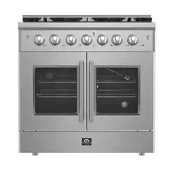
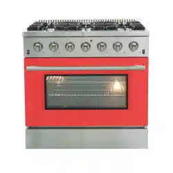
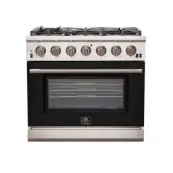
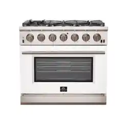
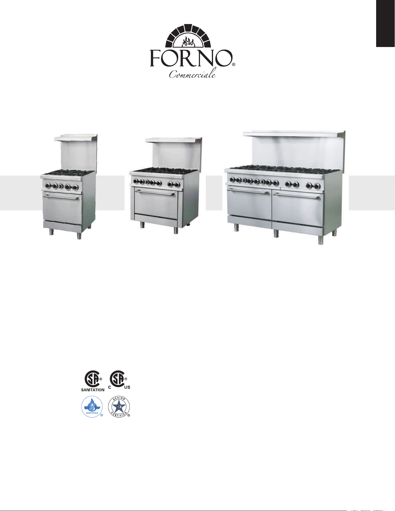
FCMGR0093-24(4 BURNER TOP)
FCMGR0093-36(6 BURNER TOP)
FCMGR0093-60(10 BURNER TOP)
ANSI Z83.11 • CSA 1.8-(2016) Food Service Equip.
Conforms to ANSI STD Z83.11-2016
Certified to CSA STD 1.8-2016 Food Service Equip.
CONFORMS TO NSF/ANSI 4:2020
FORNO COMMERCIALE
GAS RANGE OVEN


TABLE OF CONTENTS
Customer Care 4
Important For Your Safety 5
6Installation, Operation and Care
15
16
Troubleshooting Guide
Conversion Kit Instructions
Warranty 19
4
Thank you for purchasing a Forno product. Please read the entire instruction manual before operating your new appliance
for the first time. Whether you are an occasional user or an expert, it will be beneficial to familiarize yourself with the safety
practices, features, operation and care recommendations of your appliance.
Both the model and serial number are listed inside the product. For warranty purposes, you will also need the date of
purchase .
Record this information below for future reference.
Product Information Service Information
Use these numbers in any
correspondence or services calls
concerning your product.
If you received a damaged product,
immediately contact Forno.
To save time and money, before you
call for serviced, check the
troubleshooting guide. It listed the
causes of minor operation problems
that you can correct yourself.
Customer Care
Product Information Service Information
Model Number : _________________________________________
Serial Number :
Date of Purchase :________________________________________
Purchase Address And Phone:
_______________________________________________________
_______________________________________________________
_____________________
“Need some quick help? Simply scan the qr code and get access
to our fast support form. We’re always here to assist you with any
questions or concerns you may have. So, don’t hesitate to reach out!”
Services in Canada and Untied States
Keep the instruction manual handy to answer your questions. If you don’t understand something or need more
assistance, please visit our website for fast support. Please provide us your name, number, address,serial number
of the product that troubleshooting, proof of purchase, and a short description of the issue. A customer service
representative will contact you as soon as possible. All warranty work needs to be authorized by FORNO customer
service. All our authorized service providers are carefully selected and rigorously trained by us.

5
THIS MANUAL HAS BEEN PREPARED FOR PERSONNEL QUALIFIED TO INSTALL GAS EQUIP-
MENT, WHO SHOULD PERFORM THE INITIAL FIELD START-UP AND ADJUSTMENTS OF THE
EQUIPMENT COVERED BY THIS MANUAL.
POST IN A PROMINENT LOCATION THE INSTRUCTIONS TO BE FOLLOWED IN THE EVENT THE
SMELL OF GAS IS DETECTED. THIS INFORMATION CAN BE OBTAINED FROM THE LOCAL GAS
SUPPLIER.
NOTICE
IN THE EVENT A GAS ODOR IS DETECTED.
SHUTDOWN UNITS AT MAIN SHUTOFF VALVE
ANDCONTACT THE LOCAL GAS COMPANY
OR GASSUPPLIER FOR SERVICE.
IMPORTANT FOR YOUR SAFETY
Ranges are produced with quality workmanship and material. Proper installation, usage and maintenance of
your range will result in many years of satisfactory performance.
Suggests that you thoroughly read this entire manual and carefully follow all of the instructions provided.
THIS APPLIANCE IS EQUIPPED FOR NATURAL GAS,
for conversion to LP gas please see gas conversion instruction manual
attached. Orifices necessary for LP (propane) (natural) conversion are
provided. Please refer to page 3 the orifice size list when you do gas
conversion
6
Installation, Operation and Care
WARNING
Installation, Operation and Care:
PLEASE KEEP THIS MANUAL FOR FUTURE REFERENCE
GENERAL
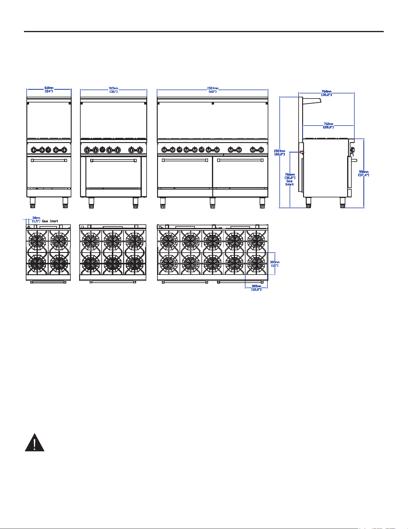
LINE DRAWING

Ranges must be installed in accordance with:
1.State and local codes.
2.National Fuel Gas Code, ANSI/Z223.1 (latest edition). Copies may be obtained from The American Gas
Association, Inc., 1515 Wilson Blvd., Arlington, VA22209.
1.Local codes.
2.CSA B149.1 Natural Gas and Propane Installation Code.
3.CSA C22.1 Canadian Electric Code.
4.CSA C22.2 Canadian Electric Code.
The above are available from the Canadian Standard Association, 5060 Spectrum Way, Suite 100,
Mississauga, Ontario, Canada L4W 5N6.
7
Installation, Operation and Care(continued)
INSTALLATION CODES AND STANDARDS
In the United States of America:
In Canada:
INSTALLATION
UNCRATING
This range was inspected before leaving the factory. The transportation company assumes full responsibility
for safe delivery upon acceptance of the shipment. Immediately after unpacking, check for possible shipping
damage. If the range is found to be damaged, save the packaging material and contact the carrier within 15
days of delivery.
Uncrate unit carefully and place in a work-accessible area as near to its final installed position as possible.
Remove all shipping wire and wood blocking.
Before installing, check the type of gas supply (natural or propane) to make sure they agree with the specifica-
tions on the rating plate located on the inside of the lower kick panel. If the supply and equipment requirements
do not agree, do not proceed with the installation. Contact your dealer or company immediately.
LOCATION
The appliance must be installed under a ventilation hood.
The equipment area must be kept free and clear of combustible substances.
The range, when installed, must have a minimum clearance from combustible construction of 12" (304 mm) at
the sides and 10" (253 mm) at the rear. Clearance from non-combustible construction is 0" at the sides and 6"
(152 mm) at the rear.
The installation location must allow adequate clearances for servicing and proper operation. A minimum front
clearance of 40" (1016 mm) is required.
The range must be installed so that the flow of combustion and ventilation air will not be obstructed. Adequate
clearance for air openings into the combustion chamber must be provided. Make sure there is an adequate
supply of air in the room to allow for combustion of the gas at the burners.
For adapt to the ground level, should be adjust four foot.
8
Installation, Operation and Care(continued)
Backsplash
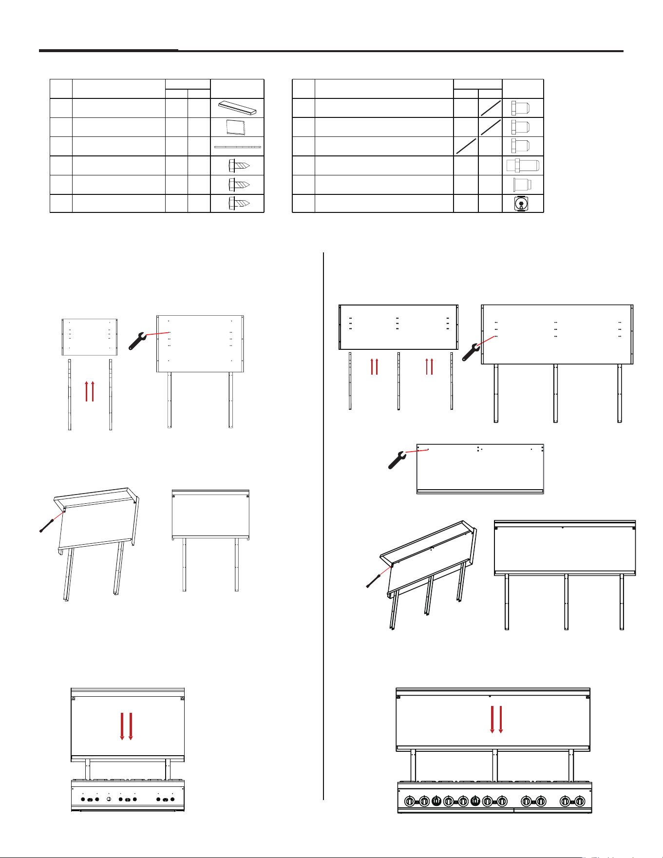
The standard Restaurant Range is equipped with a 23" (600 mm) high backsplash and shelf.
1.Remove the backsplash components from the
crating materials.
2.Assemble the required components as shown.
3.Tighten the four screws to secure the shelf.
4 Lift the assembly up, sliding the channels
into the space provided at the rear of the range.
No.
1
2
3
4
5
6
Accessory
Top shelf plate
Backsplash assemly
Backsplash column support
FCMGR0093-24 screw
FCMGR0093-36 screw
FCMGR0093-60 screw
Fig No.
7
8
9
10
11
12
Accessory
FCMGR0093-24 Top burner orifice
FCMGR0093-36 Top burner orifice
FCMGR0093-60 Top burner orifice
Oven orifice
Oven pilot orifice
Regulators
Fig
24''/36''
1
1
2
10
30
40
Q'TY
48''/60''
1
1
3
10
30
40
24''/36''
4
6
1
1
1
Q'TY
48''/60''
10
2
2
1
1.Remove the backsplash components from the
crating materials.
2.Assemble the required components as shown.
3.Tighten the nut to secure the post
4.Tighten the four screws to secure the shelf.
5 Lift the assembly up, sliding the channels
into the space provided at the rear of the range.
For 24" & 36" For 48" & 60"
LEVELING
GAS CONNECTIONS
CAUTION: All gas supply connections and any pipe joint compound used
must be resistant to the action of propane gases.
Check the leveling of the range. Place a level inside the oven cavity across the oven rack(s). Level
front-to-back and side-to-side.
To adjust the leveling, tilt the range to one side and, using channel locks, unscrew the adjustable leg
insert as required. Repeat this procedure as necessary for each leg.
Optional casters for this range are of the non-adjustable type. Therefore, the floor must be level.
If floor surface is not level, the range will experience cooking problems.
Each range is factory-equipped for the type gas specified on the rating plate. The installation gas connec-
tion is a 3/4" (19 mm) 14 FPT ANSI schedule #40 standard pipe. Connect gas supply. Make sure the
pipes are clean and free of obstructions. Codes require that a gas shutoff valve be installed in the gas line
ahead of the range. Standard ranges are equipped with fixed burner orifices which coincide with installa-
tion elevation. Install the gas pressure regulator.
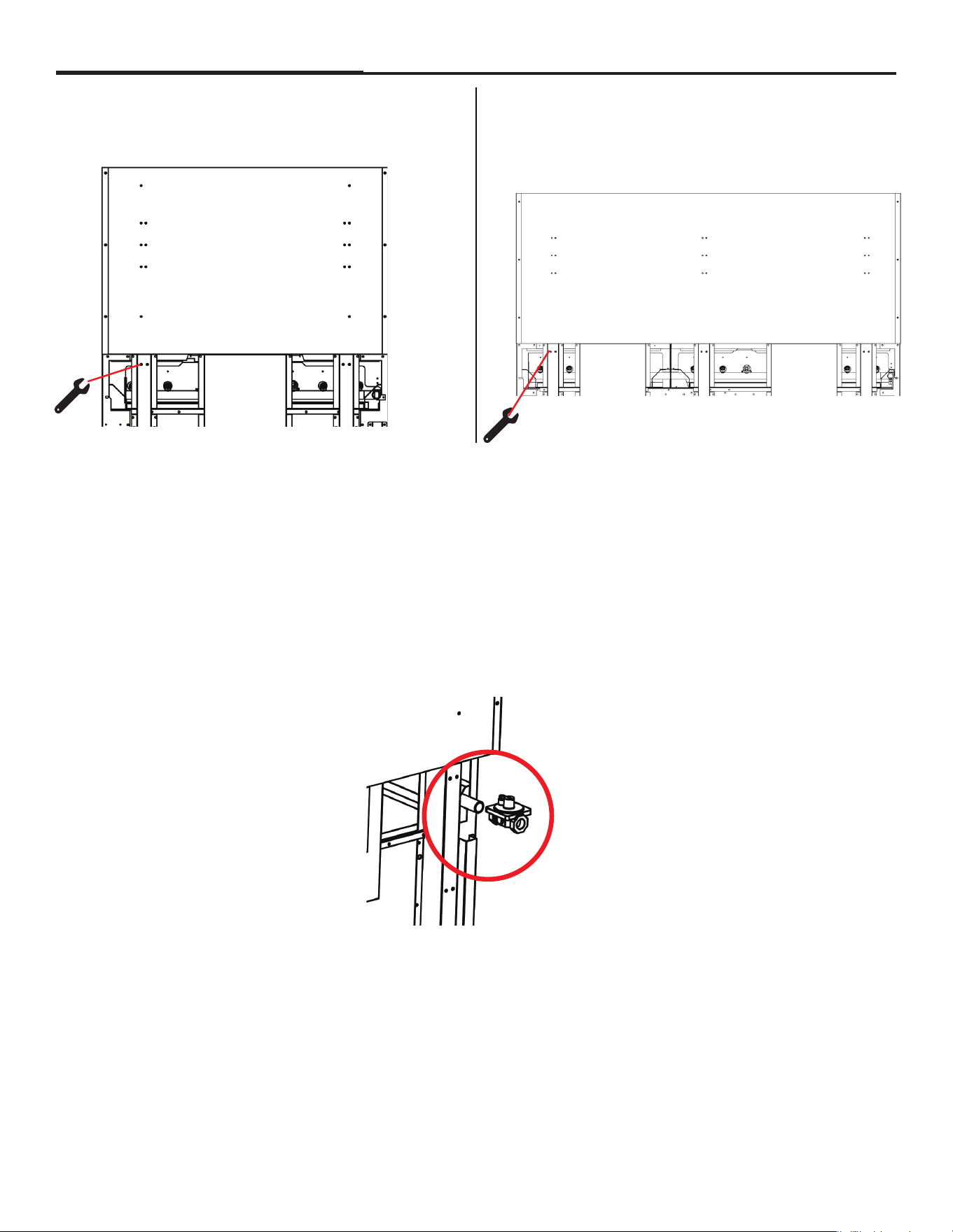
5.Install Eighteen #10 sheet metal screws
(6 to each channel leg)
9
Installation, Operation and Care(continued)
5.Install Four #10 sheet metal screws
(2 to each channel leg)
10
Installation, Operation and Care(continued)
TESTING THE GAS SUPPLY SYSTEM
Before installing, ensure that regulator supplied agrees with rating plate gas supply. The gas pressure
regulator is NOT factory installed. The regulator for this gas type is sealed within a plastic bag attached to
the oven rack inside the oven cavity. This regulator must be field installed by a qualified installer.
Natural gas regulators are preset for 5" W.C. (Water Column) (1.25 kPa); propane gas regulators for
10.0" W.C. (2.5 kPa)
1.Locate 3/4" (19 mm) gas connection pipe extending from rear of range.
2.Cover pipe threads with leak sealant.
3.Screw regulator hand-tight onto pipe with regulator arrow pointing towards range body back .
4.Using pipe wrench, tighten regulator securely in an upright position .
The arrow on the regulator shows the direction of the gas flow. The pressure regulator must be mounted
horizontally to ensure proper preset outlet pressure. If the regulator is installed in any other position, the
outlet pressure must be reset for proper operation.
A leak limiter is supplied with every regulator to allow excess gas pressure to escape. Do not obstruct
leak limiter on gas pressure regulator, as obstruction may cause regulator to malfunction.
WARNING: PRIOR TO LIGHTING, CHECK ALL JOINTS IN THE GAS SUPPLY LINE FOR LEAKS. USE
SOAP AND WATER SOLUTION. DO NOT USE AN OPEN FLAME.
After piping has been checked for leaks, all piping receiving gas should be fully purged to remove air.
Before operation, verify thermocouple is securely seated in the safety valve. The thermocouple should
be tightened a 1/4 turn past finger tight. DO NOT OVERTIGHTEN. Over-tightening may damage the
thermocouple or safety magnet.
When gas supply pressure exceeds 1/2 psig (3.45 kPa), the range and its individual shutoff valve must be
disconnected from the gas supply piping system.
When gas supply pressure is 1/2 psig(3.45kPa) or less, the range should be isolated from the gas supply
system by closing its individual manual shutoff valve until the range is ready for start-up.
5.Install Eighteen #10 sheet metal screws
(6 to each channel leg)
WARNING
This product can expose you to chemicals including [Lead & Lead Compounds], which is [are] known
to the State of California to cause cancer, birth defects and / or reproductive harm. To minimize
exposure to these substances. Always operate this unit according the Owner’s Manual, and ensure
that you provide proper ventilation. For more information go to www.P65Warnings.ca.gov

11
Installation, Operation and Care(continued)
OPERATION
FLUE CONNECTIONS DO NOT obstruct the flow of flue gases from the flue located on the rear of the
range. It is recommended that the flue gases be ventilated to the outside of the building through a ventila-
tion system installed by qualified personnel.
From the termination of the flue to the filters of the hood venting system, a minimum clearance of 18"
(457 mm) must be maintained.
Information on the construction and installation of ventilating hoods may be obtained from the standard
for the "Removal of Vapors from Commercial Cooking Equipment”, NFPA No. 96 (latest edition), available
from The National Fire Protection Association, Batterymarch Park, Quincy, MA 02269.
WARNING: THE RANGE AND ITS PARTS ARE HOT. BE VERY CAREFUL WHEN OPERATING,
CLEANING OR SERVICING THE RANGE.
12
Installation, Operation and Care(continued)
All adjustment procedures associated with pilot lighting must be performed by an authorized vender
installation or service person.
LIGHTING AND SHUTTING DOWN PILOTS
INSTALLATION CODES AND STANDARDS
1.Turn main gas supply ON.
2.Wait 30 seconds and, using a taper, light the open top pilot
3.If pilot fails to light, turn main gas supply OFF. Wait 5 minutes and repeat the above procedures.
4.Turn one open top burner valve ON to remove air from the gas line. Turn burner OFF when gas begins
to flow.
Turn burner valve OFF; pilot will off.
Complete Shutdown
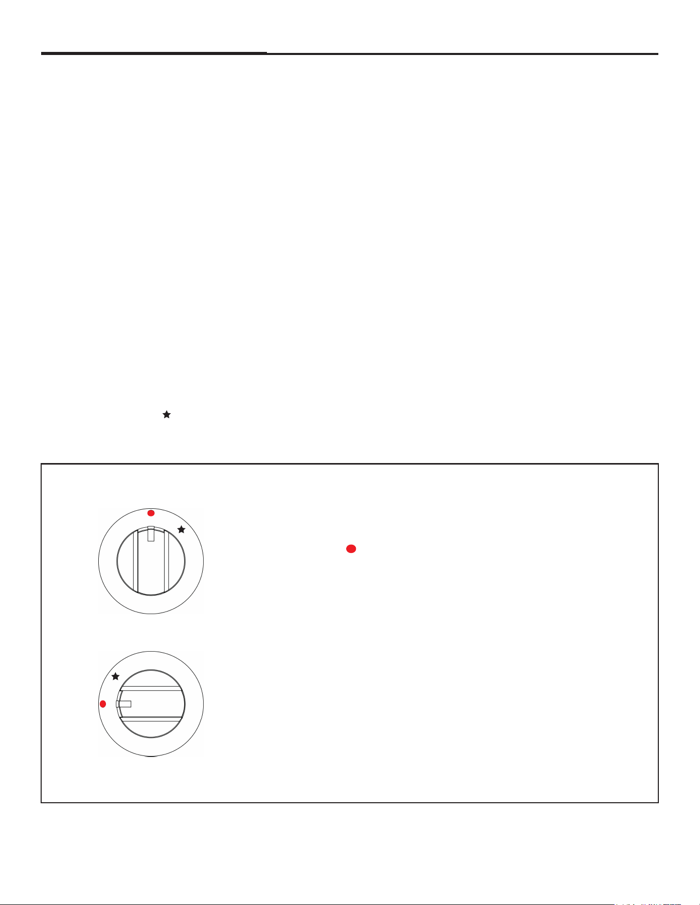
1.Turn burner valve “ ” pilot will remain lit.
2.Turn main gas supply OFF.Include main flame and pilot.
Above knob “ ” means “OFF”
“OFF”
“ON” knob Counterclockwise 90°
“ON”
13
Installation, Operation and Care(continued)
Nightly Shutdown
1.Turn oven thermostat OFF.
Complete Shutdown
1.Turn oven thermostat OFF.
2.Turn main gas supply OFF.
RACK ARRANGEMENT -STANDARD OVEN
The standard oven has three rack positions and is supplied with one two oven racks. Additional
racks may be obtained through a vender parts depot.
STANDARD OVEN LIGHTING AND SHUTDOWN INSTRUCTIONS NOTE:
Light open top/griddle pilots before lighting oven pilot.
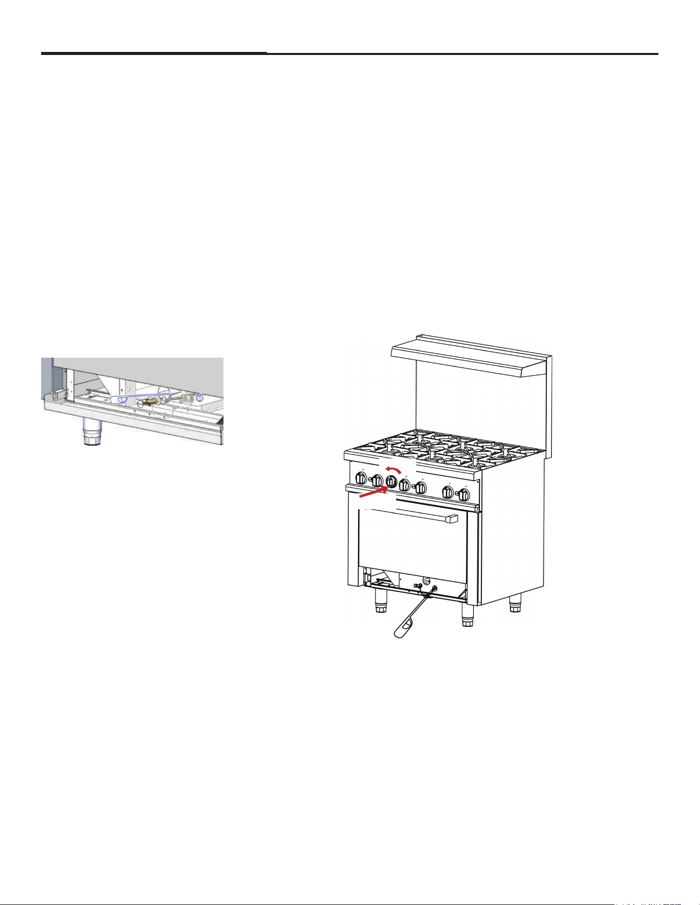
PUSH
1
TURN
2
1. Turn thermostat to the“OFF”POSITION.
2. Remove the lower panel.
3. Depress down the knob and rotate to spark star anti-clockwise, Keep pressing knob at the same
time, ignite the pilot flame with fire gun via the igniation hole.
4. After the pilot flame is ignited,press the knob for more than 20 seconds to heat up the
thermocouple.
If the ignition is out when you loosen the knob,repeat this operation.
5. Keep rotating the temperature control knob anticlockwise to ignite the main burner of the oven.
6. Select appropriate temperature according to food requirement. The oven temperature can be
controlled between 250°F and 500°F.

INSERTING AND REMOVING RACK
14
Installation, Operation and Care(continued)
The oven rack has a stop to keep the rack from being pulled all the way out when unloading product. To
install rack, place rack alongside of top of side liner runners and slide rack completely to the rear of the
oven compartment until rack drops into place
To remove rack, reverse the procedure above by raising rear of oven rack stop above runner and pulling
rack forward.
PREHEATING
Standard Oven Turn thermostat control to the desired cooking temperature and preheat oven for 25
minutes. To save on gas consumption, do not operate oven at maximum heat when it is not necessary.
Turn thermostat down to 250°F (121°C) or OFF when oven is not in use or during idle cooking periods.
Griddle (optional models)
Turn the three manual gas valve knobs to full ON. After preheating for 5 minutes, turn valves down until
desired flame or heating level is achieved. Position the removable broiler grid into one of the two slide
positions, depending on which will achieve the proper product results.
CLEANING
Do not use scouring powder or abrasives anywhere on this range
Clean only using a soft cloth and mild detergent solution.
MAINTENANCE
WARNING: THE RANGE AND ITS PARTS ARE HOT. BE VERY CAREFUL WHEN OPERATING,
CLEANING OR SERVICING THE RANGE.
VENT
When cool, the vent should be checked every six months for obstructions.
SERVICE AND PARTS INFORMATION
To obtain repairs, service and parts information concerning this model, contact supplier.
When calling for service, the following information must be available: model number, serial number,
manufacture date (MD) and voltage (optional models).
15
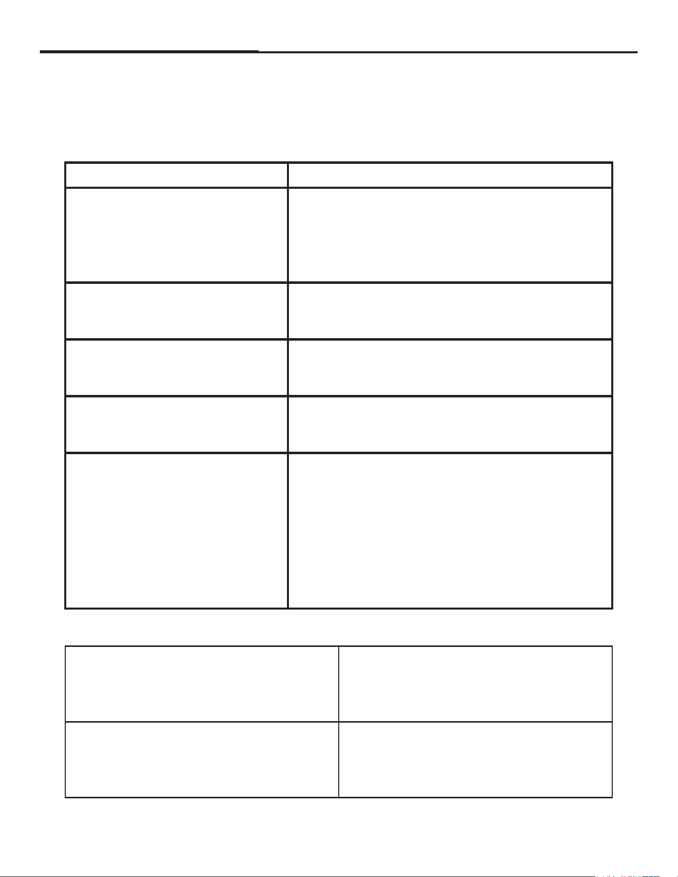
TROUBLESHOOTING GUIDE
STANDARD OVEN RESTAURANT RANGE OVEN
TROUBLESHOOTING GUIDE
PROBLEM CAUSES
1.Too much bottom heat
1a. Too low temperature
1b. Side burning
1c. Too much top heat
a) Insufficient ventilation
b) Improper fluing
c) Improper thermostat bypass setting
d) Thermostat out of calibration
e) Fluctuating gas pressure
a) Overactive flue
b) Not level front to back; check casters and legs
c) Door not closing properly
a) Too low temperature (overcooking)
b) Too long baking time
c) Thermostat calibration
a) Pilot flame to low
b) Restriction in pilot orifice
c) Problem with shutoff valve
d) Possible fluing problems
e) Low pressure
f) Improper gas line sizing
g) Burner box cover not properly installed
h) Oven cavity requires resealing
a) Not level side to side
b) Oven burner, bottom or baffles improperly installed
c) Warped pans
2. Uneven bake side to side
3. Uneven bake front to rear
4. Dried out products
5. Pilot outage
TOP BURNER OPERATION
1. Improper burner combustion
Excessive valve handle temperatures
Sticking top burner valves
a) Improper ventilation
b) Poor door fit
c) Oven door left open
d) improper use of excessively large pans or pots
a) Insufficient input
b) Poor air-gas adjustment
c) Restriction in pilot orifice
d) Restriction in main burner ignition port
2. Poor ignition
16
Conversion Kit Instructions
WARNING
Conversion Kit Instructions
for the Gas restaurant ranges
CONVERSION
Turn off the main gas supply before doing any maintenance.
This conversion kit shall be installed by a qualified service agency in accordance with the manufactur-
er’s instructions and all applicable codes and requirements of the authority having jurisdiction. If the
information in these instructions is not followed exactly, a fire, an explosion or production of carbon
monoxide may result causing property damage, personal injury or loss of life. The qualified service
agency is responsible for the proper installation of this kit. The Installation is not proper and complete
until the operation of the converted appliance is checked as specified in the manufacturer’s instructions
supplied with the kit.”
Instructions are for conversion from Natural Gas to Propane (L.P.) on 24” & 36”&60” models. The conversion
should be done before connecting the unit to the gas supply. Units are shipped from the factory equipped for
use on natural gas. Parts necessary for L.P. (liquid propane) are provided with the unit. Please refer to page
5 the orifice size list when you do gas conversion..
Do not attempt gas conversion by yourself. Gas conversion of your unit is to
be made by a certified/licensed technician.
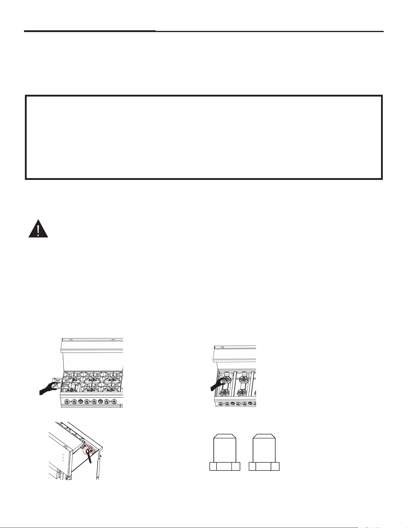
1.Remove the top grate
2. Raise the top burner and pull,
Exposed the orifice.
WARNING
Range Conversion Kit Instructions
NAT
41# 53#
L.P.
3. Loose orifice by hex wrench.
4. Replace orifice and locked.
Note: orifce number markd on orifice
17
Conversion Kit Instructions
38#
53#
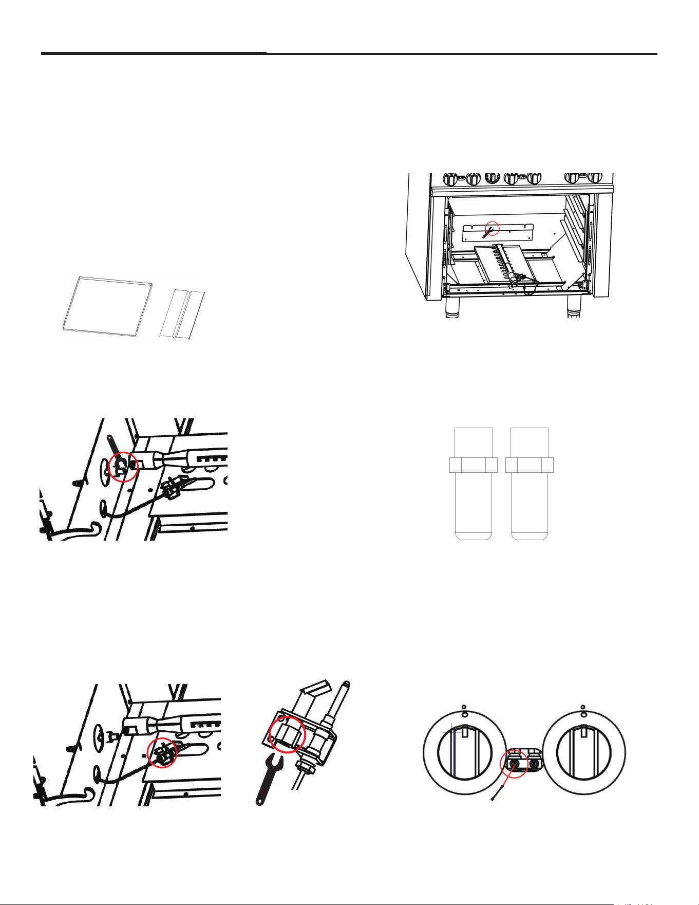
5. Put back top burner, Caution: air shutter
must be toward orifice.
6. Put back top grate.
7. Remove the oven bottom drop pan,
and radiator plate.
8. Loose the screw of oven burner back,
raise burner and pull backward.
9. Loose orifice by hex wrench
11. Use a wrench to loosen the screw
of the pilot brackt
10. Replace orifce and locked.
Note: drill size marked on orifice
LPNAT
12. Adjust flame size
18
Conversion Kit Instructions
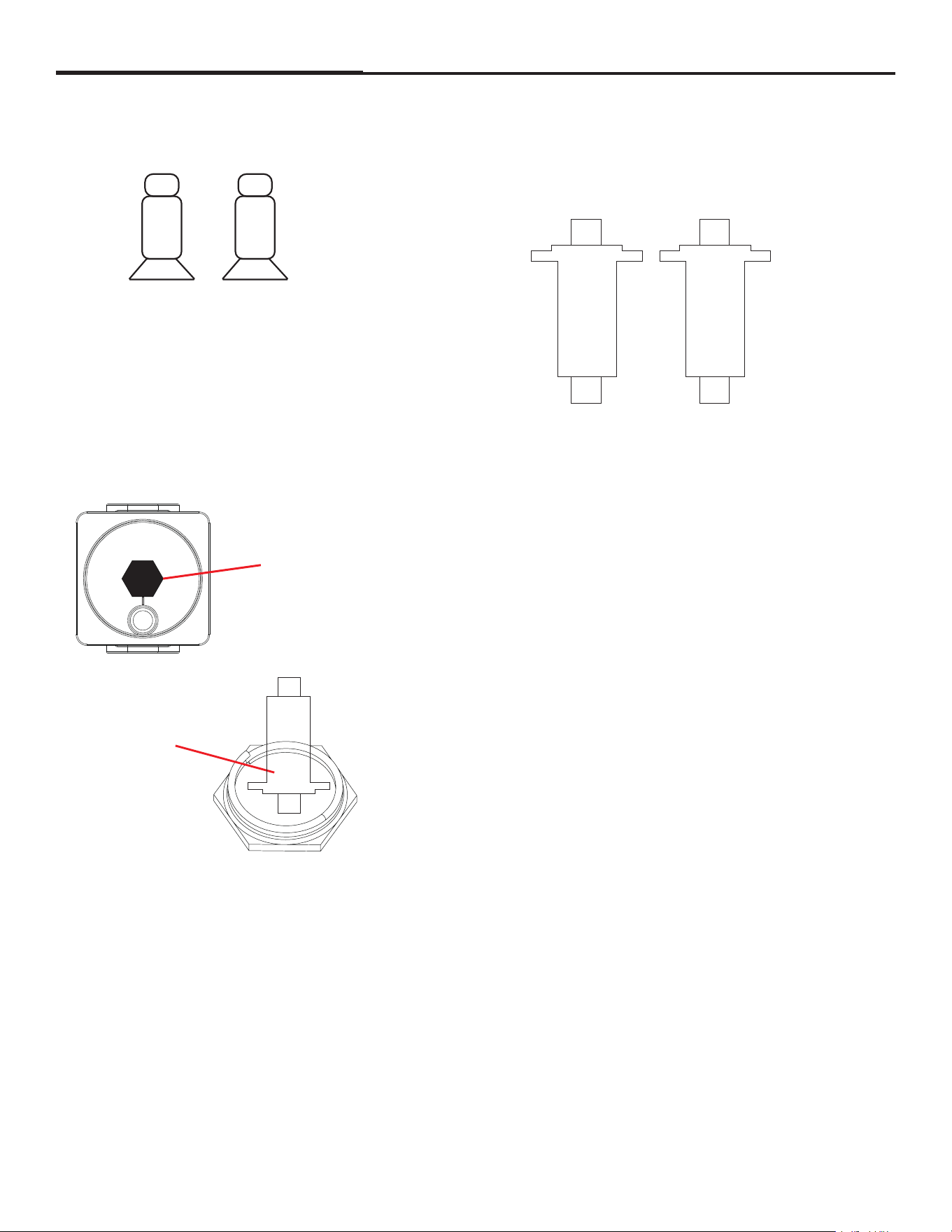
16. Regulator convert
17. Continue with installation.
Pictured is the plastic insert. Pull off insert from
octagon cap and reverse the plastic insert
position so that the L.P. position is attached to
the octagon cap head.
Before installing the included convertible regula-
tor, unscrew the octagon cap. You can read (NAT)
on the plastic insert attached to the head of the
cap; flip it over and snap back in place.
18. Completed gas conversion.
19. Check all joints in the gas supply line for leaks.
use soap and water solution. do not use an open flame.
Convertible
regulator with
octagon cap.
Unscrew from
regulator.
L.P. Position of
insert.Regulator
is now converted
to L.P.
L.P. Position
13. Replace pilot orifce and locked.
Note: drill size marked on orifice body
14. Put back oven burner,
Caution: air shutter must be toward orifice,
lock burner fix screw
15. Put back radiator plate and drop pan.
LP
NAT
LP
NAT
LP
NAT
NG 22
LPNG
0.25
mm
19
Warranty
What this limited warranty covers:
• applies
exclusively to the original Forno appliance
an
authorized Forno dealer, distributor, or retailer, and installed
in the United S
must remain
within the country of original purchase.
•
year from the
date of original retail purchase and covers parts and labor.
•
• ited to commercial use. Any
residential use of the Product will void this warranty.
• Forno Appliances will repair or replace, at its discretion, any
component or part that proves to be defective due to
manufacturing defects in materials or workmanship under
normal commercial use during the warranty period. Repair or
replacement will be performed by a Forno Authorized Service
provider during normal working hours.
•
installation, misuse, abuse,
im
Purchaser is responsible for ensuring the Product is
reasonably accessible for service.
•
age is non-transferable. In the event of
replacement of parts or the entire Product, the replacement
will assume the remaining warranty period from the original
period will not be extended.
Important
Retain proof of original purchase to establish the warranty period.
liability on any claim of any kind, with respect to the
goods and/or services provided, shall in no event exceed the
value of the product, service, or part thereof which has given rise
to the claim.
30-Day Cosmetic Warranty
Purchaser must inspect the Product at the time of delivery.
Forno warrants that the Product is free from manufacturing-
related cosmetic defects in materials and workmanship for a
period of thirty
days from the date of original retail
purchase.
• Paint blemishes
•
Cosmetic warranty does NOT cover:
•
Damage resulting from improper transportation, handling, or
dents, warping, deformation, or
damaged components, cracked or damaged glass
components
• variations in painted or enameled parts
• Differences caused by lighting conditions, installation
location, or similar factors
• Stains, corrosion, or discoloration caused by external
substances or environmental conditions
• costs
• Display models, floor m open-box,
products, or demo units
What Exclusion: What is not covered
• Installation services at the time of purchase or during product
replacement.
• Use of the Product in any residential or non-commercial
application
• Use of the Product for purposes other than its intended use
• Service or repairs performed by anyone other than a Forno
Authorized Service provider
• Damage or repair services required to correct work performed
by unauthorized parties or the use of unauthorized parts.
• Installation not in accordance with local/state/county fire
codes, electrical codes, gas codes, plumbing codes, building
codes, laws or regulations.
• Defects or damage due to improper storage of the Product.
• Defects, damage or missing parts on products sold out of the
original factory packaging or from displays.
• Service calls or repairs to correct an incorrect installation of
the Product and/or related accessories.
• Replacement of parts/service calls to connect, convert or
otherwise repair the electrical wiring and/or gas line in order
to properly use the product.
• Replacement of parts/service calls to provide instructions and
information on the use of the Product.
• Replacement of parts or service calls to correct issues arising
from use of the Product in a manner inconsistent with normal
and customary commercial use.
• Replacement of parts/service calls due to wear and tear of
components such as seals, knobs, pan supports, shelving,
cutlery baskets, buttons, touch displays, scratched or broken
ceramic-glass tops.
• Replacement of parts/service calls for lack of/improper
maintenance, including but not limited to: build up of residues,
stains, scratches, discoloration, corrosion.
• Defects and damages arising from accidents, alteration,
misuse, abuse or improper installation.
• Defects and damages arising from Product transport, logistics
and handling. Inspection of the product must be made at time
of delivery. Following receipt and inspection, the selling
dealer/delivery company must be notified of any issues
arising from handling, transport and logistics.
• Defects or damage resulting from external forces beyond the
control of Forno Appliances, including but not limited to wind,
rain, sand, fire, flooding, mudslides, freezing temperatures,
excessive moisture or prolonged exposure to humidity, power
surges, lightning, structural failures surrounding the
appliance, or other natural phenomena.
• Products whose serial number has been altered/damaged/
tampered with. In no case shall Forno be held liable or
responsible for damage to surrounding property, including
furniture, cabinetry, flooring, panels, and other structures
surrounding the Product. Forno is neither liable nor
responsible for the Product if it is located in a remote area or
an area where certified trained technicians are not reasonably
available. Purchaser must bear any transportation and
delivery costs of the Product to the nearest Authorized
Service Center or the additional travel expenses of a certified
trained technician.
• Chips

20
Warranty (continued)
There are no warranties, either express or implied, other than those listed and described above, including but not limited
to any implied warranties of merchantability or fitness for a particular purpose, that shall apply after the express warranty
period stated above.
No other express warranty or guarantee given by any person, firm, or corporation with respect to this Product shall be
binding on Forno.
Forno shall not be liable for any loss of revenue or profits, failure to realize expected savings or other benefits, time away
from work, loss of food or beverages, travel or lodging expenses, costs to rent or purchase replacement appliances, or
any remodeling or construction expenses.
Forno shall also not be liable for any indirect, incidental, special, or consequential damages arising from the use, misuse,
or inability to use this Product, regardless of the legal theory on which the claim is based, and even if Forno has been
advised of the possibility of such damages.
In no event shall Forno’s total liability exceed the purchase price of the Product giving rise to the claim.
The Purchaser assumes all risk and liability for any loss, damage, or injury to persons or property resulting from the use,
misuse, or inability to use the Product, except where such damage is directly caused by the negligence of Forno.
This limited warranty is non-transferable, applies only to the original Purchaser, and constitutes the Purchaser’s
exclusive remedy.
DISCLAIMER OF WARRANTIES AND LIMITATION OF LIABILITY

Customer Support: Call 1-866-231-8893 or email: [email protected]