

Technical Support and E-Warranty Certificate www.vevor.com/support
LINE SCRIBING MACHINE
RFS-065/RFS-050
We continue to be committed to provide you tools with competitive price.
"Save Half", "Half Price" or any other similar expressions used by us only represents an
estimate of savings you might benefit from buying certain tools with us compared to the major top
brands and does not necessarily mean to cover all categories of tools offered by us. You are
kindly reminded to verify carefully when you are placing an order with us if you are actually saving
half in comparison with the top major brands.


1
(The picture is for reference only; please refer to the actual object)
NEED HELP? CONTACT US!
Have product questions? Need technical support? Please feel free to contact us:
Technical Support and E-Warranty Certificate www.vevor.com/support
This is the original instruction, please read all manual instructions carefully before
operating. VEVOR reserves a clear interpretation of our user manual. The
appearance of the product shall be subject to the product you received. Please
forgive us that we won't inform you again if there are any technology or software
updates on our product.
RFS-065/RFS-050
2
SAFETY INSTRUCTION AND PRECAUTIONS
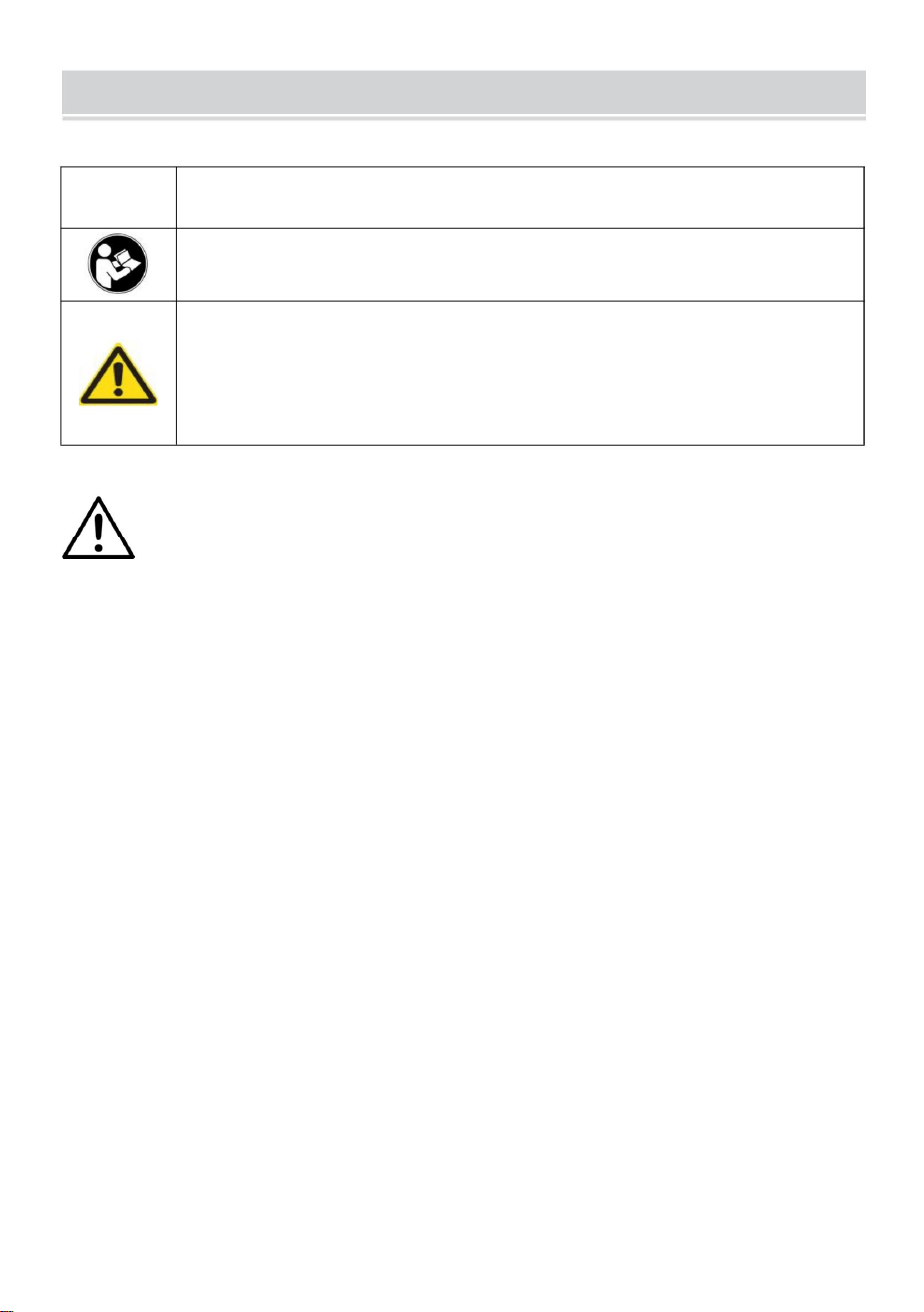
Symbol
Symbol Description
Warning: To reduce the risk of injury, the user must read the
instructions manual carefully.
This symbol, placed before a safety comment, indicates a kind of
precaution, warning, or danger. Ignoring this warning may lead to
an accident. To reduce the risk of injury, fire, or electrocution,
please always follow the recommendations shown below.
WARNING:To reduce the risk of injury, the user must read the
instructions manual carefully.
1.Use as intended only. The product is not a toy, and it cannot be played by
children to prevent children from hurting themselves by mistake.
2.The product cannot be used to injure people maliciously.
3.Keep away from open flame.
3.Keep away from sharp points, blades and other items, so as not to
scratch the product.
SAVE THESE INSTRUCTIONS
3
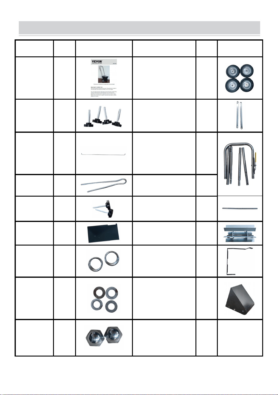
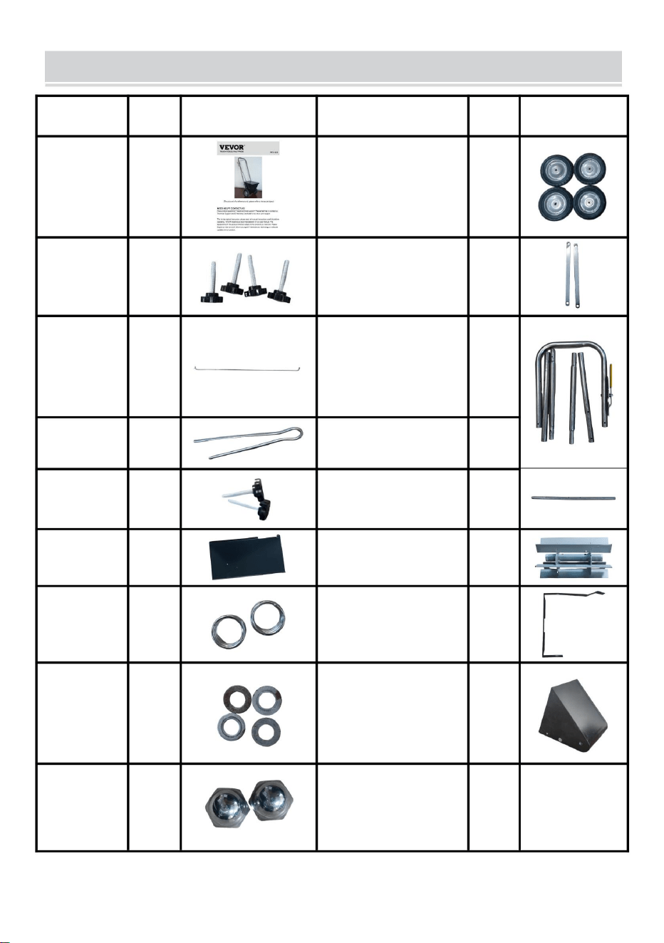
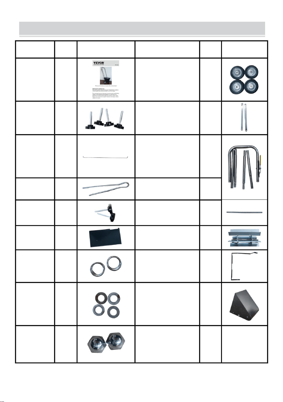
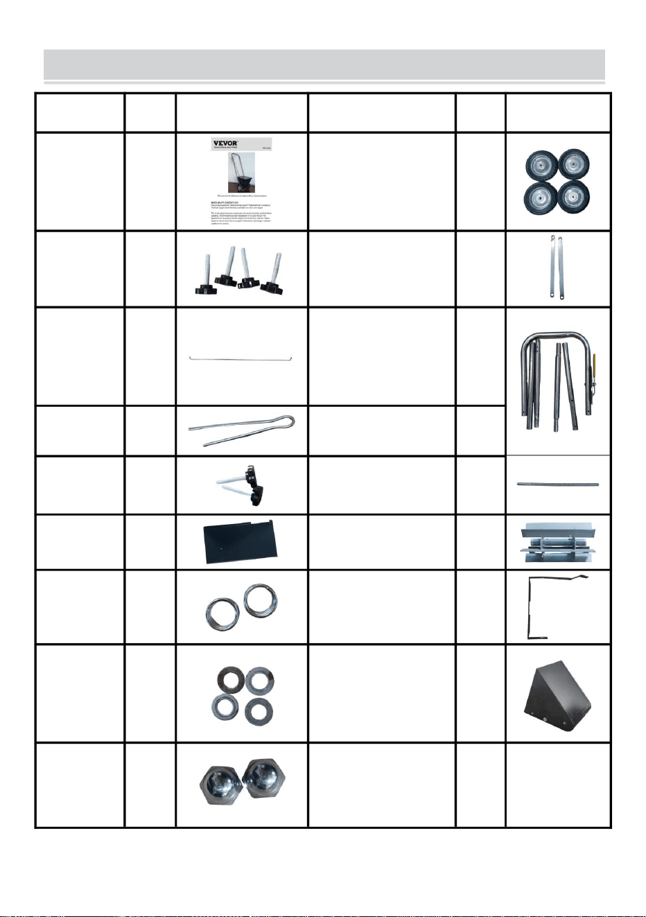
PART LIST
ITEM
QTY
PIC
ITEM
QTY
PIC
A-User
manual
1
J-wheel
4
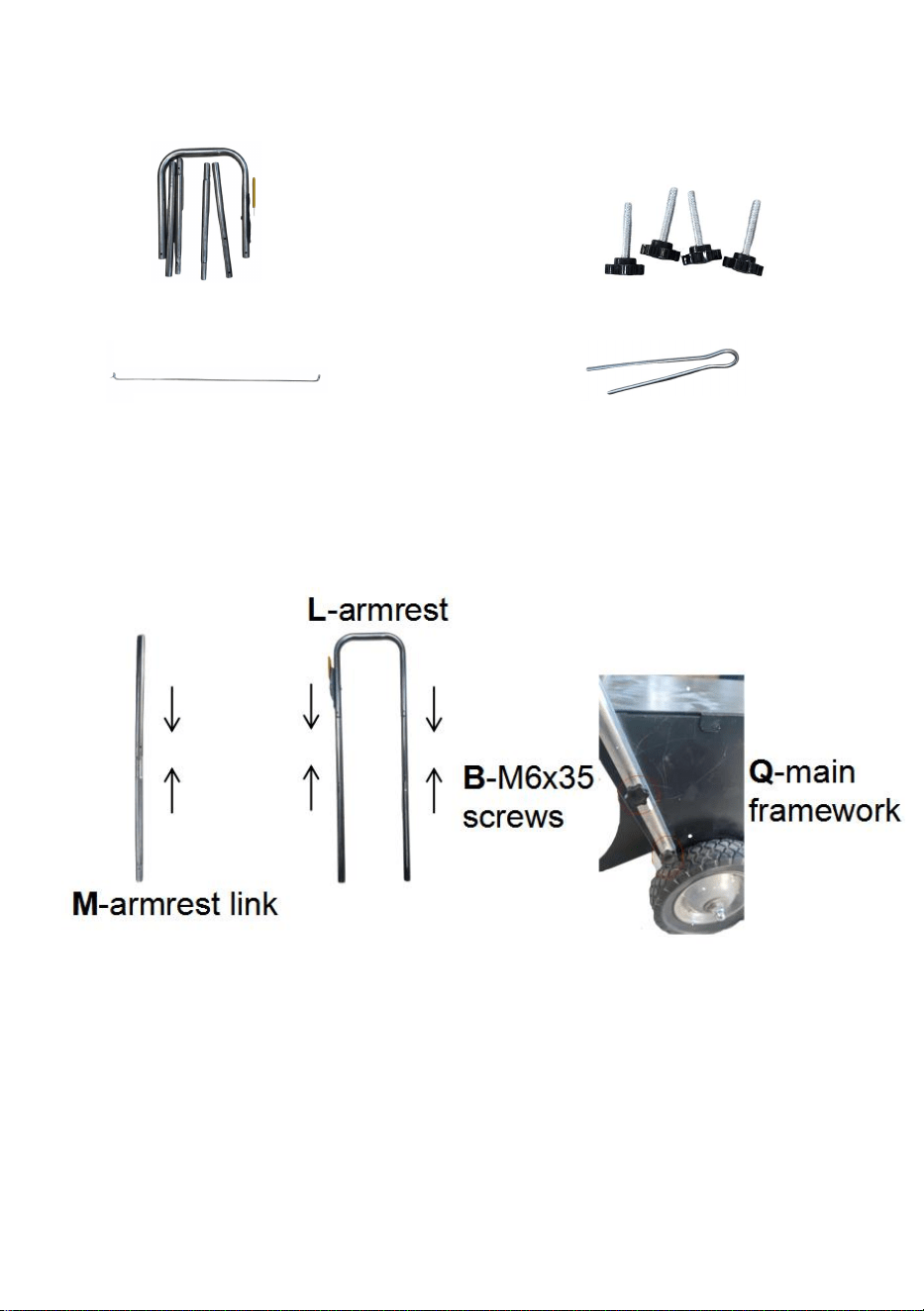
B-M6x35
screws
6
K-support pole
2
C-gear
lever
1
L-armrest
(including
pre-installed control
module)
1
D
-split pin
3
M
-armrest link
4
E-M4x12
screws
2
N-wheel axle
2
F-cover
1
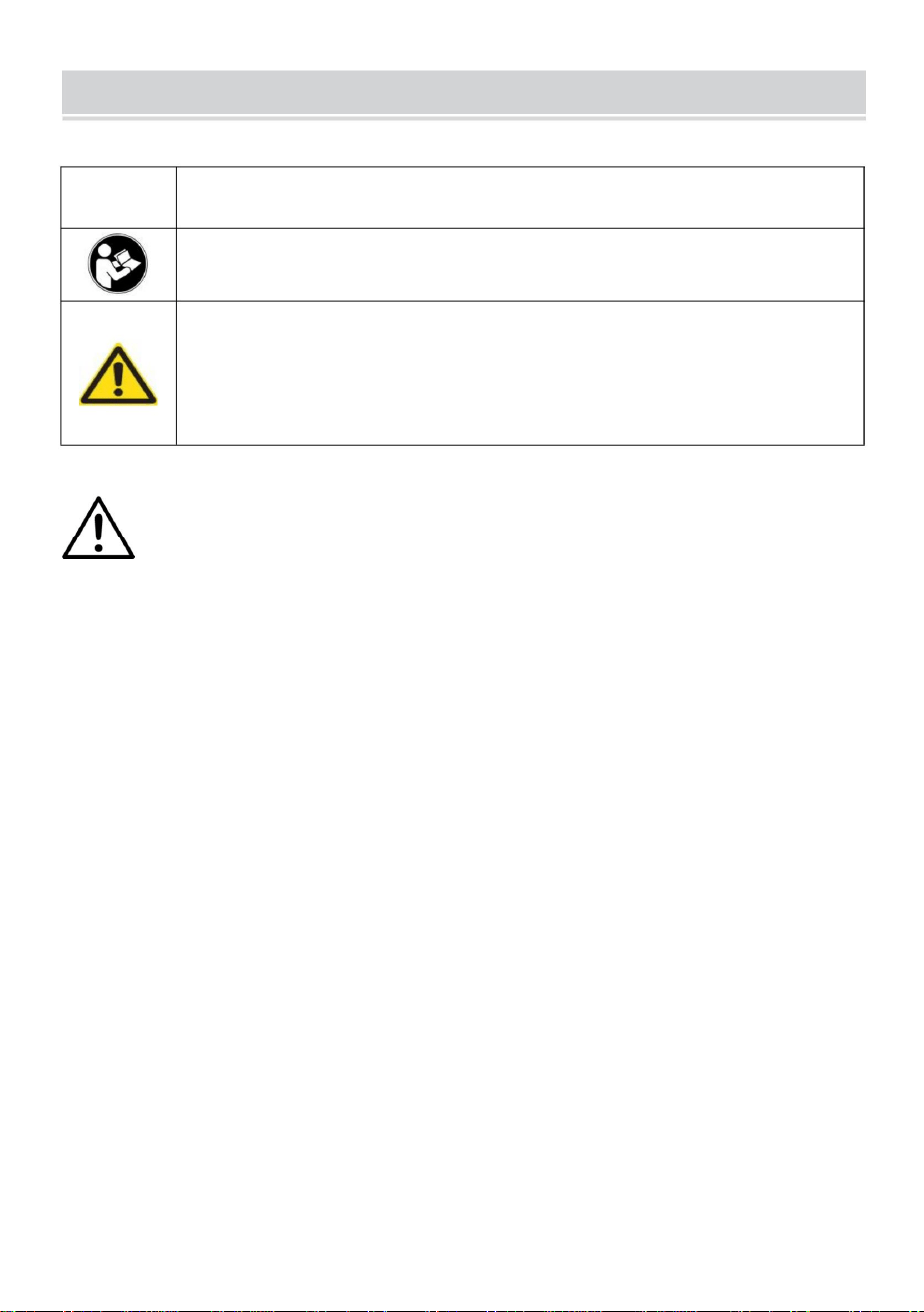
O-mixer
1
G
-short
spring
4
P
-powder baffle
1
H-gasket
8
Q-main framework
1
I
-M12x12
round
head nut
4
(The picture is for reference only; please refer to the actual object)
4
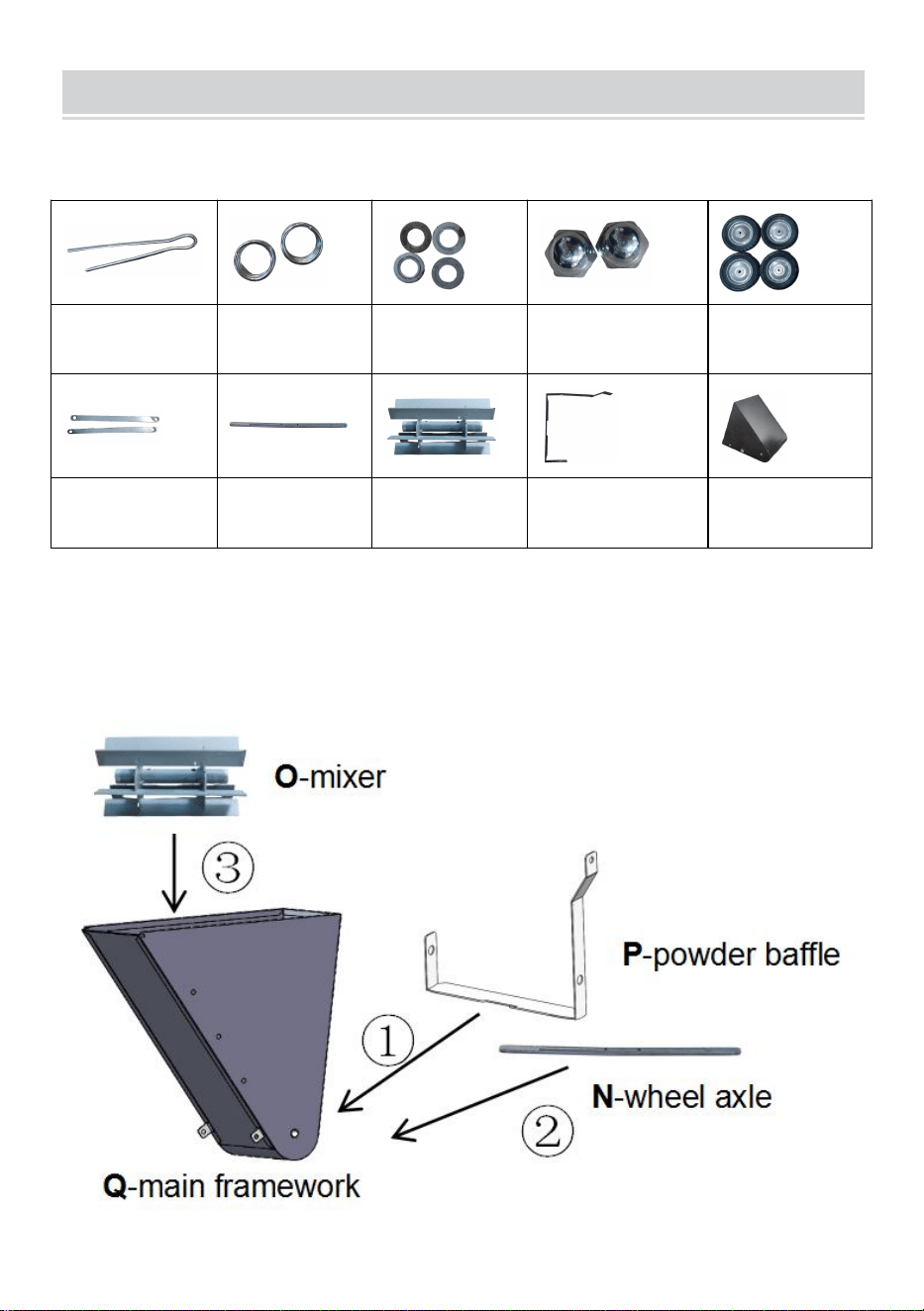
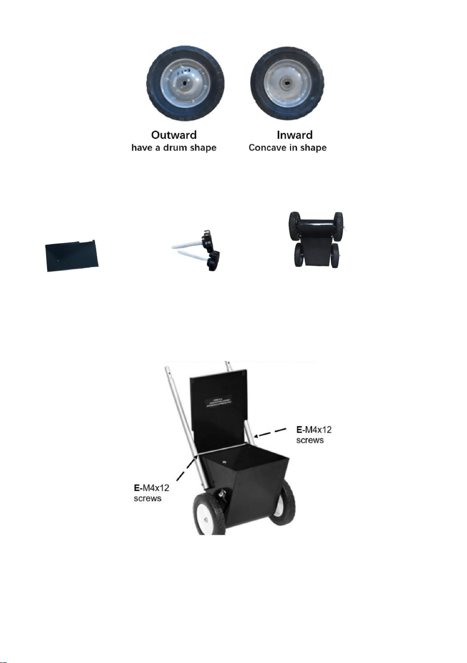
INSTALLATION
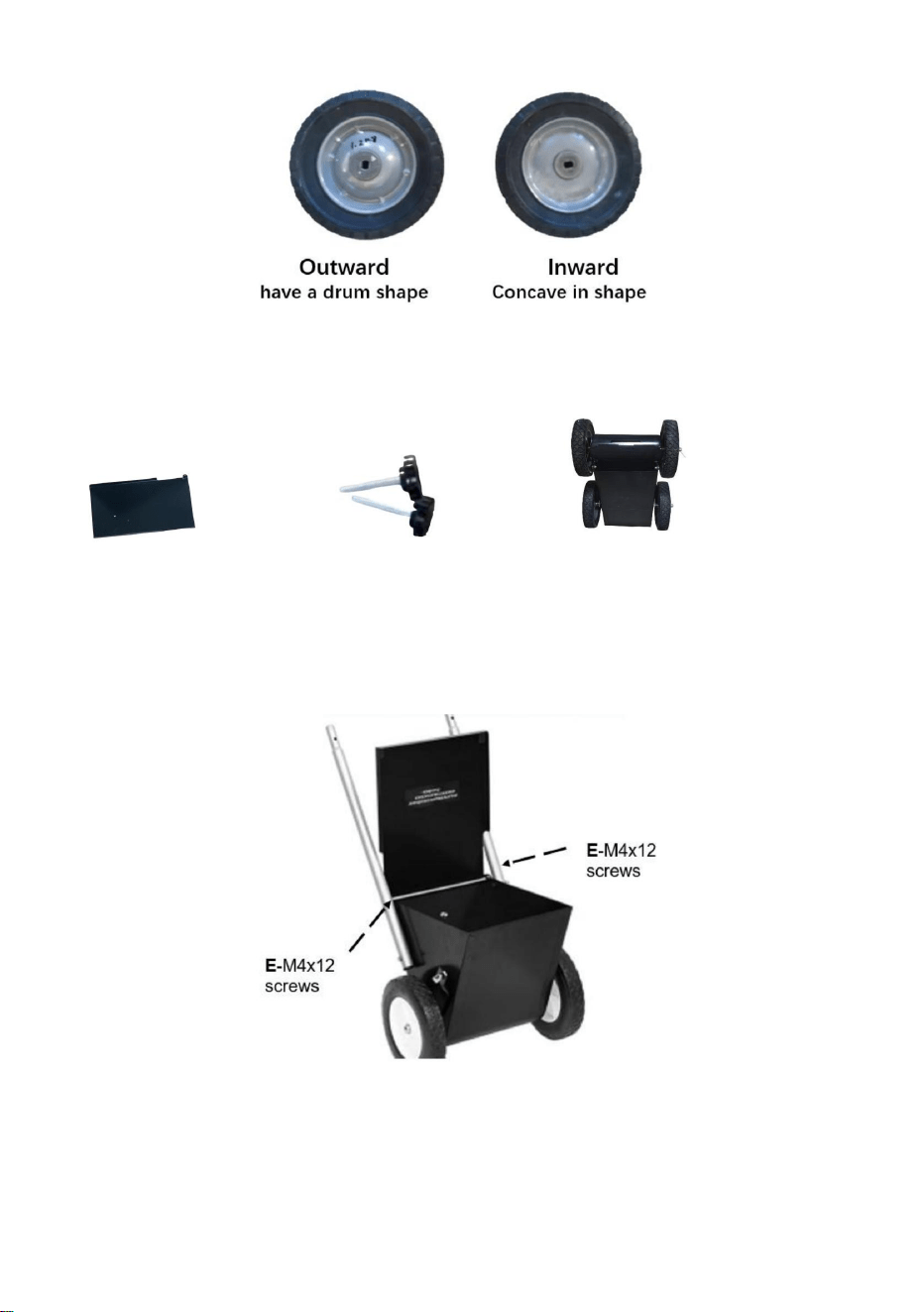
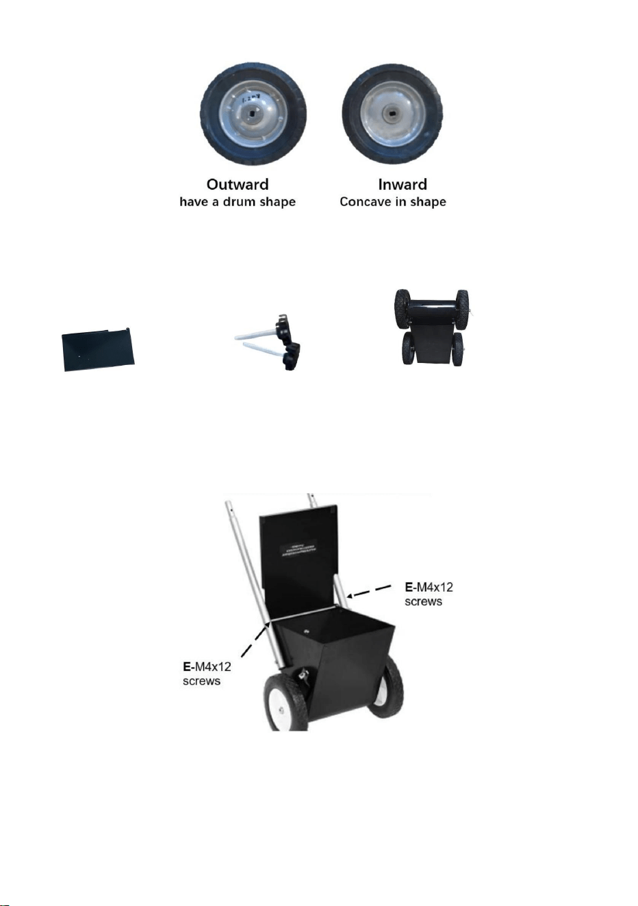
STEP1: Install the wheels
Prepare the following items.
D
-split pin*2
G
-short spring*4
H
-gasket*8
I
-M12x12 round
head nut*4
J-wheel*4
K
-support pole*2
N
-wheel axle*2
O
-mixer*1
P
-powder baffle*1
Q
-main
framework*1
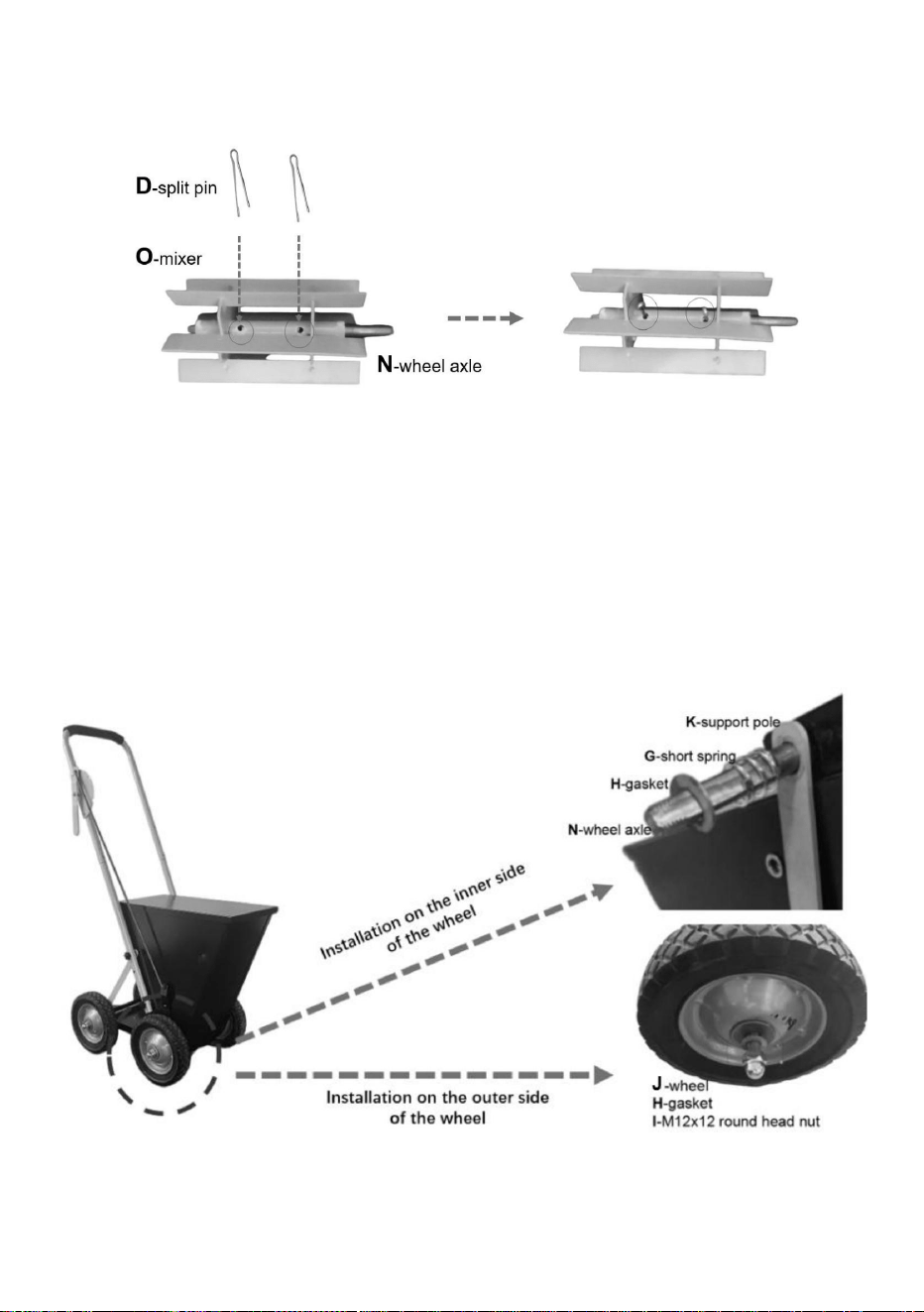
Firstly, align the holes of the P-powder shuffle and Q-main framework.Paying
attention to the orientation of the P-powder baffle as shown in the figure.Then
thread the N-wheel axle through the P-powder baffle, Q-main framework, and
O-mixer in sequence.

5
Align the holes of the O-mixer and N-wheel axle, and then insert the D-split pin.
Fold the split pin if necessary.
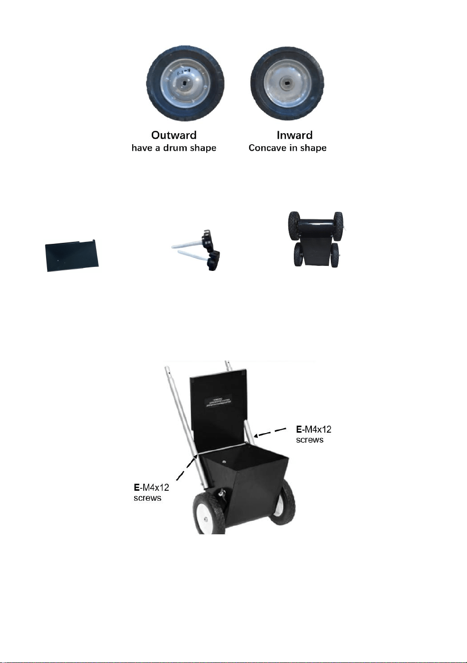
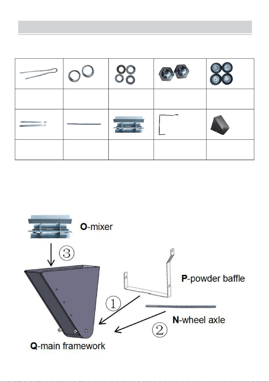
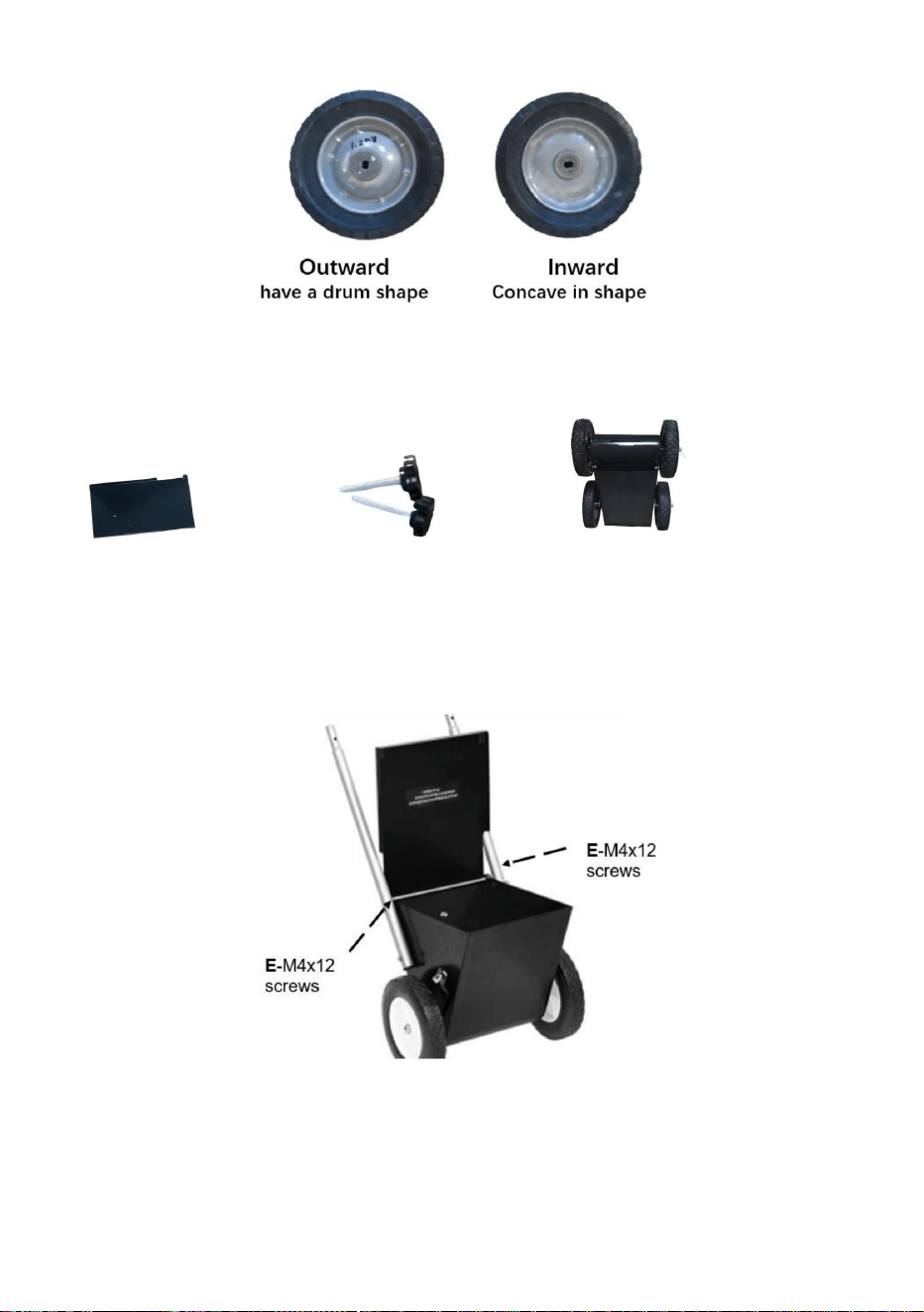
Install one K-support pole, one G-short spring, one H-gasket, one J-wheel, and
one H-gasket into one side of the axle in order, and then lock them with I-M12 nut.
Pay attention to the orientation of the J-wheel. Repeat the steps for another wheel.
The steps for the rest wheels are similar (not having the O-mixer and K-support
pole).
6
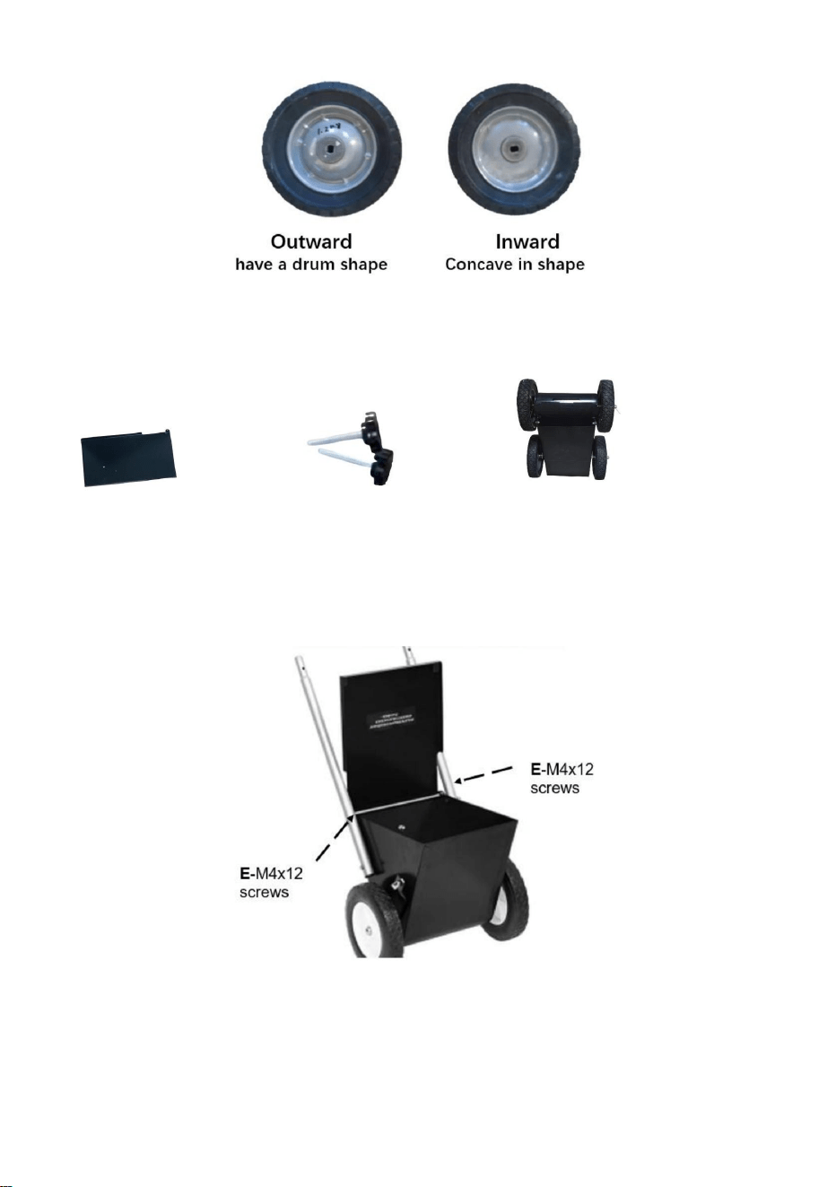
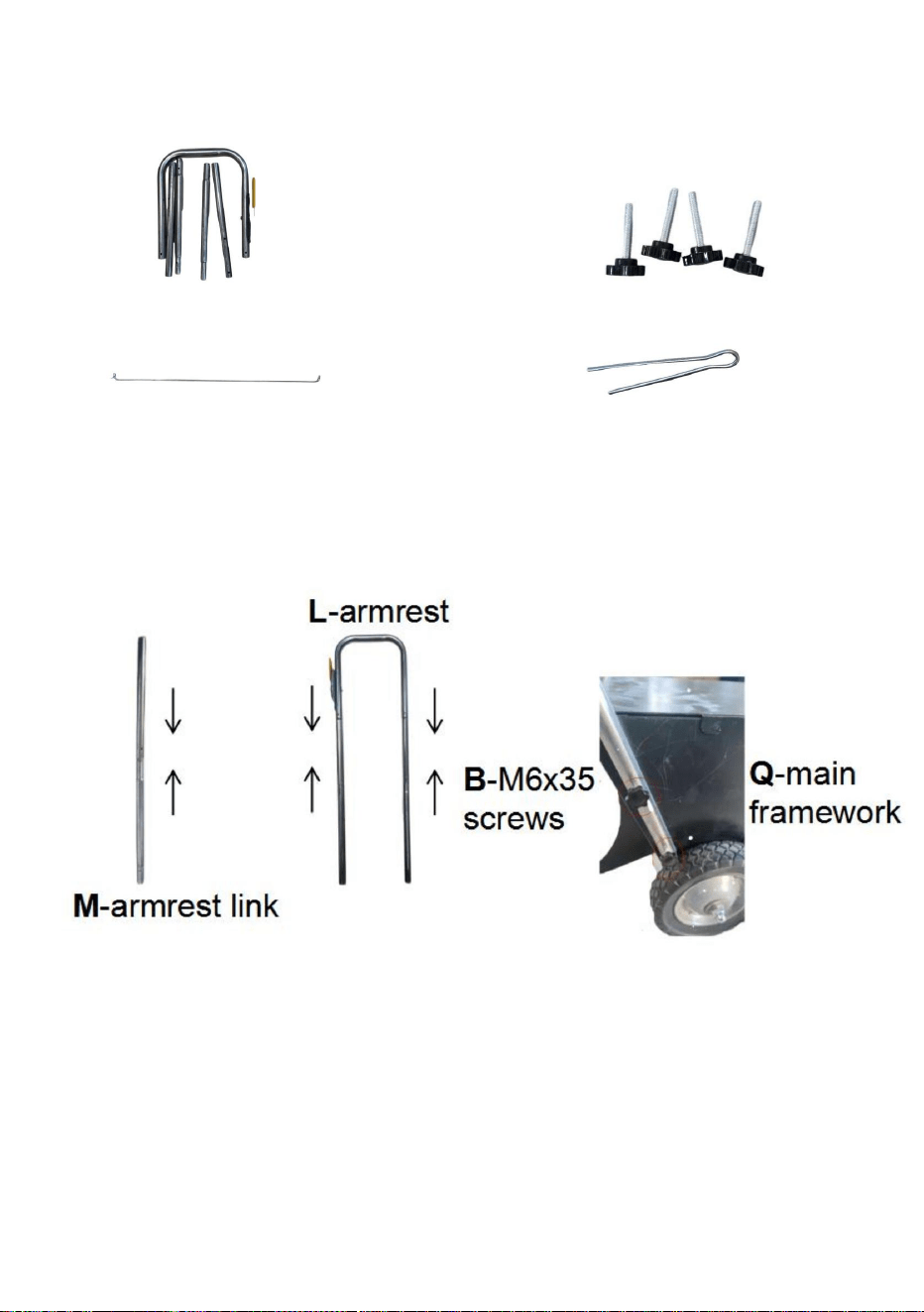
STEP2: Install the cover
Prepare the following items.
Align the holes on the F-cover and Q-main framework, and tighten them with
E-M4x12 screws.
F-cover*1
E-M4x12 screws*2
Installed parts
7
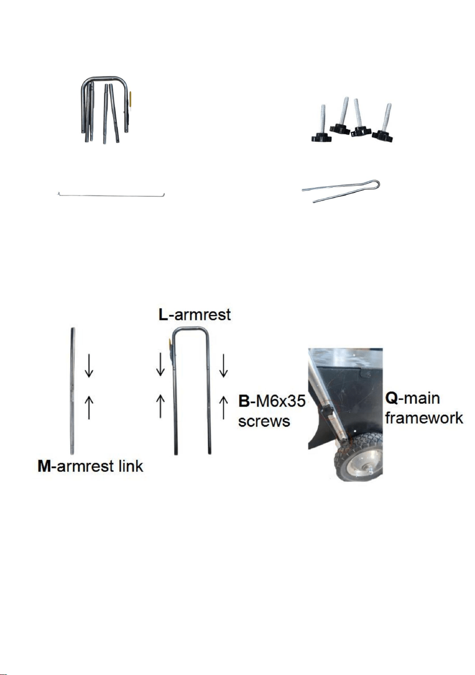
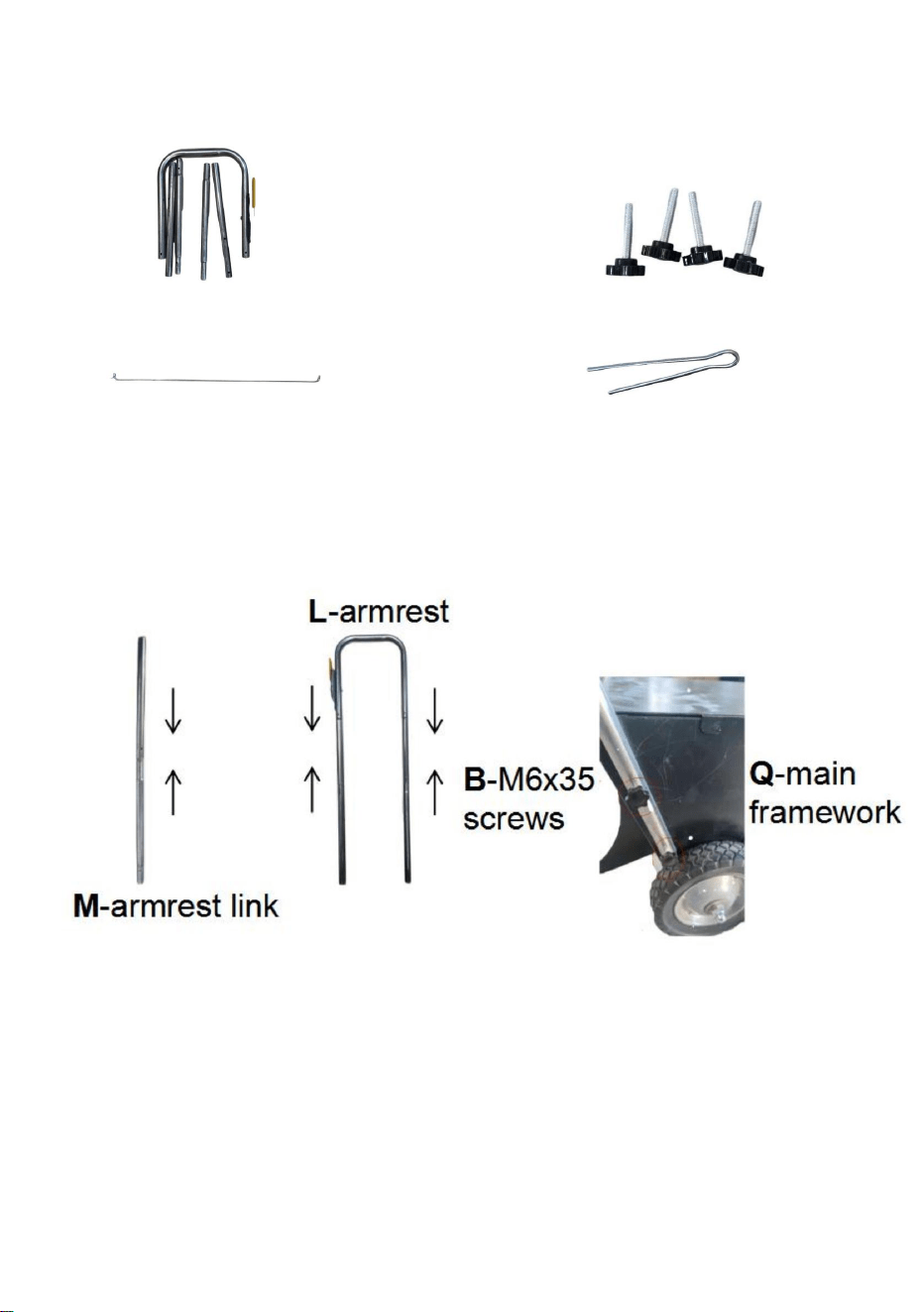
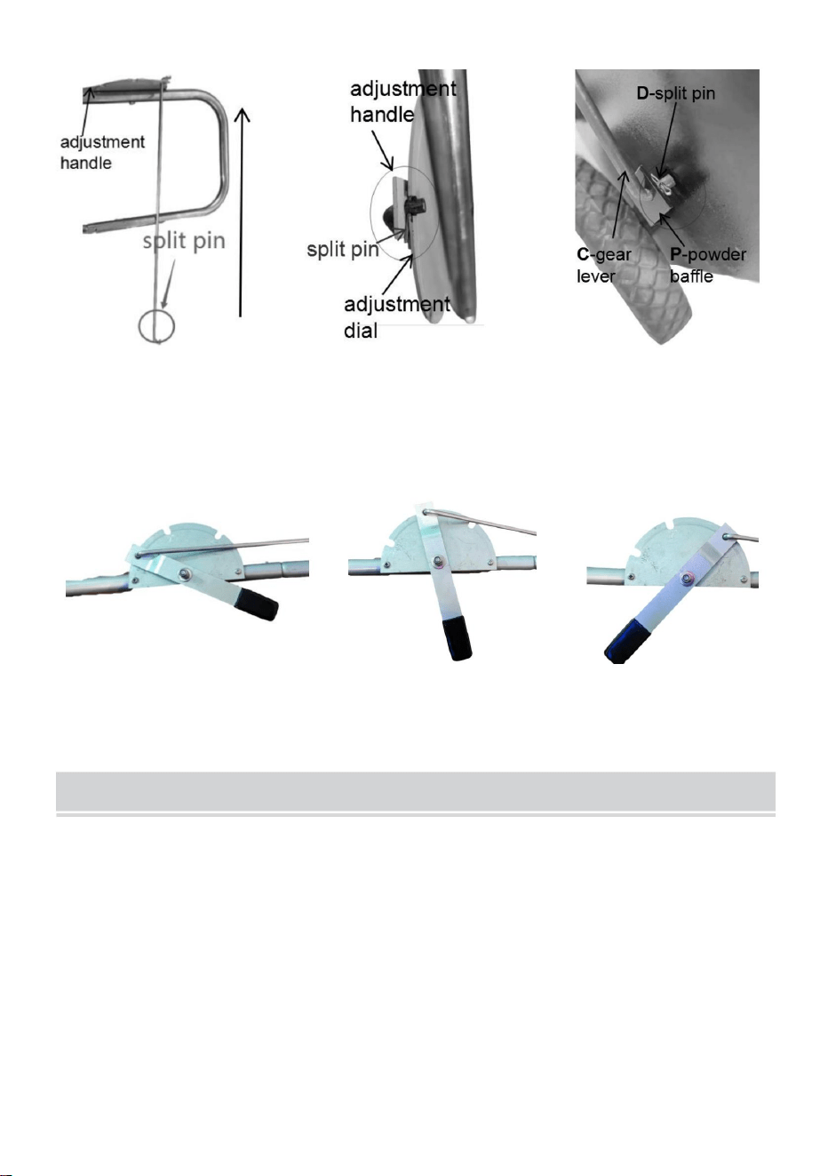
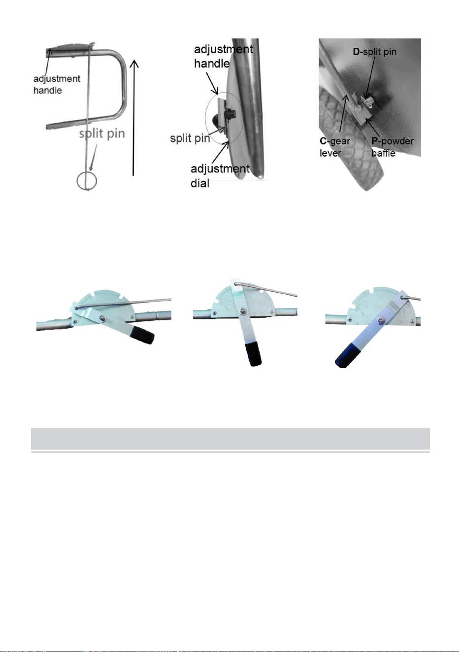
STEP3: Install the adjustment component
Prepare the following items.
Connect the M-armrest links in pairs and then connect them to the L-armrest. Align
the holes of the M-armrest links, K-support pole and Q-main framework, and
tighten them with B-M6x35 screws.
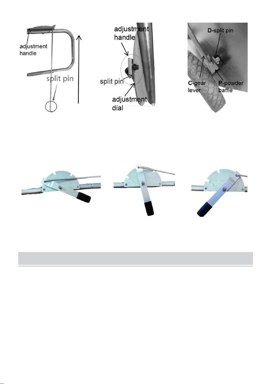
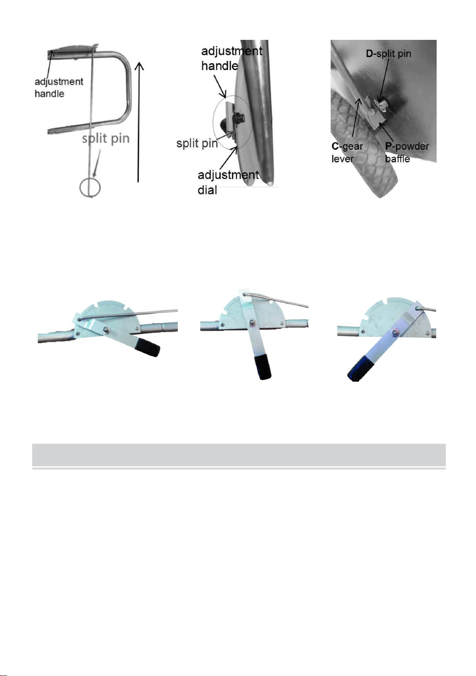
Insert the C-gear lever without a pin into the hole of the adjustment handle, and
clamp the pin between the adjustment handle and the adjustment dial. Then, insert
the C-gear lever into the hole of the P-powder baffle and fix it with the D-split pin.
B-M6x35 screws*6
L-armrest (including pre-installed control module)*1
M-armrest link*4
C-gear lever*1
D-split pin*1

8
STEP4:Adjust the line width
As shown in the figure, there are three gears (off, 2", 4" )on the adjustment dial.
Insert the gear lever into different positions to obtain the corresponding line width.
TIPS
1.Before Line Striping, make sure to clean the ground and keep it dry.
2.The effect is related to the forward speed. We recommend a forward
speed of 0.15m/s.Adjustments can be made according to the actual
situation.


MACCHINA PER TRACCIARE LE LINEE
"Risparmia la metà", "Metà prezzo" o qualsiasi altra espressione simile da noi utilizzata rappresenta
solo una stima del risparmio che potresti ottenere acquistando determinati utensili con noi rispetto ai principali
marchi principali e non significa necessariamente coprire tutte le categorie di utensili da noi offerti. Ti
ricordiamo gentilmente di verificare attentamente quando effettui un ordine con noi se stai effettivamente
risparmiando la metà rispetto ai principali marchi principali.
Continuiamo a impegnarci per fornirvi strumenti a prezzi competitivi.
Codice RFS-065/RFS-050
Supporto tecnico e certificato di garanzia elettronica www.vevor.com/support
Machine Translated by Google

Machine Translated by Google

Questa è l'istruzione originale, si prega di leggere attentamente tutte le istruzioni del
manuale prima di utilizzare. VEVOR si riserva una chiara interpretazione del
nostro manuale utente. L'aspetto del prodotto sarà soggetto al prodotto ricevuto. Vi
preghiamo di perdonarci se non vi informeremo di nuovo se ci sono aggiornamenti
tecnologici o software sul nostro prodotto.
(L'immagine è solo a scopo illustrativo; fare riferimento all'oggetto reale)
1
HAI BISOGNO DI AIUTO? CONTATTACI!
Hai domande sul prodotto? Hai bisogno di supporto tecnico? Non esitare a contattarci: Supporto tecnico
e certificato di garanzia elettronica www.vevor.com/support
Codice RFS-065/RFS-050
Machine Translated by Google
Attenzione: per ridurre il rischio di lesioni, l'utente deve leggere attentamente le istruzioni per l'uso.
attentamente il manuale di istruzioni.
2. Il prodotto non può essere utilizzato per ferire volontariamente le persone.
3.Tenere lontano da fiamme libere.
bambini per evitare che si facciano male per errore.
SALVA QUESTE ISTRUZIONI
attentamente il manuale di istruzioni.
1. Utilizzare solo come previsto. Il prodotto non è un giocattolo e non può essere utilizzato da
ATTENZIONE: Per ridurre il rischio di lesioni, l'utente deve leggere attentamente le istruzioni per l'uso.
Simbolo Simbolo Descrizione
3. Tenere lontano da punte affilate, lame e altri oggetti, per non
graffiare il prodotto.
ISTRUZIONI DI SICUREZZA E PRECAUZIONI
2
precauzione, avvertimento o pericolo. Ignorare questo avvertimento può portare a
Questo simbolo, posto prima di un commento di sicurezza, indica un tipo di
un incidente. Per ridurre il rischio di lesioni, incendi o folgorazione, seguire
sempre le raccomandazioni indicate di seguito.
Machine Translated by Google

Io-M12x12
E-M4x12
G-corto
Ingranaggio C
6
Assale ruota N
Deflettore in polvere P
dado a testa
2
1
1
2
(L'immagine è solo a scopo illustrativo; fare riferimento all'oggetto reale)
1
Bracciolo a L
manuale
Perno diviso a D
Struttura Q-main
Ruota a J
1
4
1
B-M6x35
Collegamento bracciolo M
viti
primavera
girare
2
Palo di supporto K
leva
4
4
viti
1
Utente A
F-copertina
Guarnizione H
3
1
Miscelatore O
8
4
Quantità
FOTOFOTO
ARTICOLO QTY
ARTICOLO
ELENCO DEI PEZZI
controllo preinstallato
3
modulo)
(compreso
Machine Translated by Google
Preparare i seguenti elementi.
attenzione all'orientamento del deflettore di polvere P come mostrato nella figura. Quindi
infilare l' asse della ruota N attraverso il deflettore in polvere P, il telaio principale Q e
Per prima cosa, allineare i fori del P-powder shuffle e del Q-main framework.Pagamento
O-mixer in sequenza.
STEP1: Installare le ruote
INSTALLAZIONE
4
Ruota a J*4
G-molla corta*4 H-guarnizione*8
Q-principale
K-palo di supporto*2 N-asse ruota*2 O-miscelatore*1
girare
Perno diviso a D*2
dado a testa*4
Io-M12x12
Deflettore in polvere P*1
struttura*1
Machine Translated by Google

Installare un palo di supporto K, una molla corta G, una guarnizione H, una ruota J e
una guarnizione H in un lato dell'assale nell'ordine, quindi bloccarle con il dado I-M12.
Se necessario, piegare la coppiglia.
Allineare i fori del miscelatore O e dell'asse della ruota N, quindi inserire il perno diviso D.
Prestare attenzione all'orientamento della J-wheel. Ripetere i passaggi per un'altra ruota.
I passaggi per le ruote di riposo sono simili (non avendo il miscelatore O e il supporto K
palo).
5
Machine Translated by Google
Parti installate
Viti E-M4x12.
Viti E-M4x12*2F-copertina*1
Allineare i fori sul coperchio F e sulla struttura principale Q e serrarli con
Preparare i seguenti elementi.
PASSO 2: Installare la copertura
6
Machine Translated by Google

7
FASE 3: Installare il componente di
regolazione Preparare i seguenti elementi.
Collegamento bracciolo M*4
Perno diviso a D*1
Leva del cambio C*1
Bracciolo a L (incluso modulo di controllo preinstallato)*1 Viti B-M6x35*6
Collegare i collegamenti del bracciolo M a coppie e quindi collegarli al bracciolo L. Allineare i fori dei collegamenti del bracciolo
M, del palo di supporto K e della struttura principale Q e serrarli con viti B-M6x35.
Inserire la leva del cambio C senza perno nel foro della maniglia di regolazione e bloccare il perno tra la maniglia di
regolazione e il quadrante di regolazione. Quindi, inserire la leva del cambio C nel foro del deflettore della polvere P e fissarla
con il perno diviso D.
Machine Translated by Google

SUGGERIMENTI
8
Come mostrato nella figura, sulla manopola di regolazione ci sono tre marce (spento, 2", 4").
Inserire la leva del cambio in diverse posizioni per ottenere la larghezza della linea corrispondente.
2. L'effetto è correlato alla velocità di avanzamento. Consigliamo una velocità di avanzamento
velocità di 0,15 m/s. È possibile effettuare regolazioni in base alla situazione effettiva
1. Prima di tracciare le linee, assicurarsi di pulire il terreno e di mantenerlo asciutto.
PASSO 4: Regola la larghezza della linea
situazione.
Machine Translated by Google

Machine Translated by Google


RFS-065/RFS-050
MASZYNA DO TRAWIENIA LINII
Wsparcie techniczne i certyfikat gwarancji elektronicznej www.vevor.com/support
„Oszczędź połowę”, „Połowa ceny” lub inne podobne wyrażenia używane przez nas stanowią
jedynie szacunkowe oszczędności, jakie możesz uzyskać, kupując u nas określone narzędzia w porównaniu
z głównymi markami i niekoniecznie oznaczają one objęcie wszystkich kategorii narzędzi oferowanych
przez nas. Uprzejmie przypominamy, aby dokładnie sprawdzić, czy składając u nas zamówienie faktycznie
oszczędzasz połowę w porównaniu z głównymi markami.
Nadal staramy się oferować Państwu narzędzia w konkurencyjnych cenach.
Machine Translated by Google

Machine Translated by Google

POTRZEBUJESZ POMOCY? SKONTAKTUJ SIĘ Z NAMI!
(Zdjęcie ma charakter poglądowy, proszę odnieść się do rzeczywistego obiektu)
To jest oryginalna instrukcja, przed użyciem należy uważnie przeczytać wszystkie instrukcje.
VEVOR zastrzega sobie jasną interpretację naszej instrukcji obsługi. Wygląd produktu
będzie zależał od produktu, który otrzymałeś. Prosimy o wybaczenie, że nie poinformujemy
Cię ponownie, jeśli w naszym produkcie pojawią się jakiekolwiek aktualizacje technologiczne lub
oprogramowania.
Masz pytania dotyczące produktu? Potrzebujesz wsparcia technicznego? Skontaktuj się
z nami: Wsparcie techniczne i certyfikat E-Gwarancji www.vevor.com/support
RFS-065/RFS-050
1
Machine Translated by Google

dzieci, aby zapobiec przypadkowemu zrobieniu sobie krzywdy.
3. Trzymać z dala od otwartego ognia.
1. Używać wyłącznie zgodnie z przeznaczeniem. Produkt nie jest zabawką i nie może być używany przez
ZAPISZ TE INSTRUKCJE
OSTRZEŻENIE: Aby zmniejszyć ryzyko obrażeń, użytkownik musi zapoznać się z treścią niniejszej instrukcji.
2. Produkt nie może być używany w celu złośliwego wyrządzania krzywdy innym.
Przeczytaj uważnie instrukcję obsługi.
Symbol Opis symbolu
3. Trzymaj z dala od ostrych punktów, ostrzy i innych przedmiotów, aby nie dopuścić do
porysować produkt.
Ostrzeżenie: Aby zmniejszyć ryzyko obrażeń, użytkownik musi zapoznać się z treścią niniejszej instrukcji.
INSTRUKCJA BEZPIECZEŃSTWA I ŚRODKI OSTROŻNOŚCI
Przeczytaj uważnie instrukcję obsługi.
wypadek. Aby zmniejszyć ryzyko obrażeń, pożaru lub porażenia prądem, zawsze postępuj zgodnie z
zaleceniami podanymi poniżej.
Ten symbol, umieszczony przed komentarzem dotyczącym bezpieczeństwa, oznacza rodzaj
środek ostrożności, ostrzeżenie lub niebezpieczeństwo. Zignorowanie tego ostrzeżenia może prowadzić do
2
Machine Translated by Google

ZDJĘCIE
PRZEDMIOT
ILOŚĆILOŚĆ PRODUKTU
ZDJĘCIE
moduł)
wstępnie zainstalowany sterownik
(w tym
3
wiosna
B-M6x35
Łącznik podłokietnika M
śruby
okrągły
2
Słupek podporowy K
dźwignia
4
4
Okładka F
Użytkownik A
śruby
1
4
Uszczelka H
3
1
O-mikser
6
Przekładnia C
Oś koła N
P-przesłona proszkowa
8
Ja-M12x12
E-M4x12
G-krótki
1
2
2
1
(Zdjęcie ma charakter poglądowy, proszę odnieść się do rzeczywistego obiektu)
nakrętka główki
Struktura Q-main
Podłokietnik L
podręcznik
D-styk rozdzielający
1 1
4
Koło J
1
LISTA CZĘŚCI
Machine Translated by Google

Przygotuj następujące rzeczy.
D-pin rozgałęźny*2
Koło J*4
Q-główny
rama*1
nakrętka głowicy*4
G-sprężyna krótka*4 H-uszczelka*8
okrągły
Ja-M12x12
K-słupek podporowy*2 N-oś koła*2 O-mikser*1 P-deflektor proszkowy*1
KROK 1: Zamontuj koła
INSTALACJA
przeciągnij oś koła N przez przegrodę proszkową P, ramę główną Q i
O-mikser w sekwencji.
zwróć uwagę na orientację przegrody proszkowej P, jak pokazano na rysunku. Następnie
Najpierw należy wyrównać otwory w ramie P-powder shuffle i Q-main.Płatność
4
Machine Translated by Google

5
W razie konieczności złóż zawleczkę.
jedną uszczelkę H w jedną stronę osi, a następnie zablokuj je nakrętką I-M12.
Zamontuj jeden słupek podporowy K, jedną krótką sprężynę G, jedną uszczelkę H, jedno koło J i
Wyrównaj otwory w mieszalniku O i osi koła N, a następnie włóż sworzeń rozdzielający D.
Zwróć uwagę na orientację koła J. Powtórz kroki dla innego koła.
Kroki dla pozostałych kół są podobne (bez miksera O i podpory K)
Polak).
Machine Translated by Google
Zainstalowane części
Śruby E-M4x12*2F-okładka*1
Śruby E-M4x12.
6
Wyrównaj otwory w pokrywie F i ramie głównej Q i dokręć je za pomocą
Przygotuj następujące rzeczy.
KROK 2: Zamontuj pokrywę
Machine Translated by Google
7
KROK 3: Zainstaluj element regulacyjny
Przygotuj następujące elementy.
Dźwignia zmiany biegów C*1
Połącz linki podłokietnika M parami, a następnie połącz je z podłokietnikiem L. Wyrównaj otwory linków podłokietnika M, słupka
podporowego K i ramy głównej Q i dokręć je śrubami B-M6x35.
Łącznik podłokietnika M*4
Podłokietnik L (wraz z fabrycznie zainstalowanym modułem sterującym)*1 B-śruby M6x35*6
D-pin rozgałęźny*1
Włóż dźwignię C-gear bez sworznia do otworu uchwytu regulacyjnego i zaciśnij sworzeń między uchwytem regulacyjnym a
pokrętłem regulacyjnym. Następnie włóż dźwignię C-gear do otworu przegrody prochowej P i zamocuj ją za pomocą sworznia
rozporowego D.
Machine Translated by Google
PORADY
Ustaw dźwignię zmiany biegów w różnych pozycjach, aby uzyskać odpowiednią szerokość linii.
Jak pokazano na rysunku, na pokrętle regulacyjnym znajdują się trzy biegi (wyłączony, 2", 4").
1. Przed malowaniem linii należy oczyścić podłoże i utrzymać je w suchości.
sytuacja.
2. Efekt jest związany z prędkością do przodu. Zalecamy prędkość do przodu
KROK 4: Dostosuj szerokość linii
prędkość 0,15 m/s. Regulacje można wykonywać zgodnie z rzeczywistą
8
Machine Translated by Google

Machine Translated by Google


RFS-065/RFS-050
Wir sind weiterhin bestrebt, Ihnen Werkzeuge zu wettbewerbsfähigen Preisen anzubieten.
„Sparen Sie die Hälfte“, „Halber Preis“ oder andere ähnliche Ausdrücke, die wir verwenden, stellen nur eine
Schätzung der Ersparnis dar, die Sie beim Kauf bestimmter Werkzeuge bei uns im Vergleich zu den großen Topmarken
erzielen können, und decken nicht unbedingt alle von uns angebotenen Werkzeugkategorien ab. Wir möchten Sie
freundlich daran erinnern, bei Ihrer Bestellung bei uns sorgfältig zu prüfen, ob Sie im Vergleich zu den großen
Topmarken tatsächlich die Hälfte sparen.
LINIENREIßMASCHINE
Technischer Support und E-Garantie-Zertifikat www.vevor.com/support
Machine Translated by Google

Machine Translated by Google

Brauchen Sie Hilfe? Kontaktieren Sie uns!
1
Dies ist die Originalanleitung. Bitte lesen Sie alle Anweisungen sorgfältig durch, bevor Sie das Gerät in
Betrieb nehmen. VEVOR behält sich eine klare Auslegung unserer Bedienungsanleitung vor.
Das Erscheinungsbild des Produkts richtet sich nach dem Produkt, das Sie erhalten haben. Bitte
verzeihen Sie uns, dass wir Sie nicht erneut informieren, wenn es Technologie- oder Software-Updates
für unser Produkt gibt.
(Das Bild dient nur als Referenz. Bitte beziehen Sie sich auf das tatsächliche Objekt.)
Haben Sie Fragen zum Produkt? Benötigen Sie technischen Support? Bitte kontaktieren
Sie uns: Technischer Support und E-Garantie-Zertifikat www.vevor.com/support
RFS-065/RFS-050
Machine Translated by Google
2. Das Produkt darf nicht dazu verwendet werden, Menschen vorsätzlich zu verletzen.
3. Von offenem Feuer fernhalten.
Kinder, um zu verhindern, dass Kinder sich versehentlich verletzen.
3.Halten Sie sich von scharfen Spitzen, Klingen und anderen Gegenständen fern, um nicht
Lesen Sie die Bedienungsanleitung sorgfältig durch.
1.Nur bestimmungsgemäß verwenden. Das Produkt ist kein Spielzeug und kann nicht von
WARNUNG: Um das Verletzungsrisiko zu verringern, muss der Benutzer die
Symbol Symbol Beschreibung
das Produkt zerkratzen.
BEWAHREN SIE DIESE ANWEISUNGEN AUF
Lesen Sie die Bedienungsanleitung sorgfältig durch.
Warnung: Um das Verletzungsrisiko zu verringern, muss der Benutzer die
SICHERHEITSHINWEISE UND VORSICHTSMASSNAHMEN
2
Vorsichtsmaßnahme, Warnung oder Gefahr. Das Ignorieren dieser Warnung kann zu
Dieses Symbol vor einem Sicherheitshinweis weist auf eine Art
ein Unfall. Um das Risiko von Verletzungen, Bränden oder Stromschlägen zu
verringern, befolgen Sie bitte immer die unten aufgeführten Empfehlungen.
Machine Translated by Google

Menge
BildBild
ARTIKELMENGE
ARTIKEL
8
E-M4x12
G-kurz
I-M12x12
6
C-Gang
N-Radachse
P-Pulverblendung
Kopfmutter
1
2
2
1
(Das Bild dient nur als Referenz. Bitte beziehen Sie sich auf das tatsächliche Objekt.)
Q-Hauptrahmen
Handbuch
L-Armlehne
D-Splintstift
J-Rad
1
4
1
B-M6x35
M-Armlehnenverbindung
Schrauben
1
Frühling
runden
Hebel
K-Stützstange
2
4
4
F-Abdeckung
H-Dichtung
Schrauben
A-Benutzer
1
1 4
3
O-Mischer
TEILELISTE
vorinstallierte Steuerung
3
Modul)
(einschließlich
Machine Translated by Google

Bereiten Sie die folgenden Gegenstände vor.
J-Rad * 4
G-Kurzfeder*4 H-Dichtung*8
Q-Haupt
Rahmen*1
runden
D-Splintstift*2
Kopfmutter * 4
I-M12x12
P-Pulverblendung*1K-Stützstange*2 N-Radachse*2 O-Mischer*1
SCHRITT 1: Montieren Sie die Räder
INSTALLATION
fädeln Sie die N-Radachse durch die P-Pulverblendung, das Q-Hauptgerüst und
Achten Sie auf die Ausrichtung der P-Pulverblendung, wie in der Abbildung gezeigt.
Richten Sie zunächst die Löcher des P-Powder-Shuffles und des Q-Main-Frameworks aus.
O-Mischer in Reihe.
4
Machine Translated by Google

5
Gegebenenfalls den Splint umklappen.
Setzen Sie der Reihe nach jeweils eine H-Dichtung auf eine Seite der Achse ein und befestigen Sie sie anschließend mit der I-M12-Mutter.
Installieren Sie eine K-Stützstange, eine G-Kurzfeder, eine H-Dichtung, ein J-Rad und
Richten Sie die Löcher des O-Mischers und der N-Radachse aus und setzen Sie dann den D-Splintstift ein.
Achten Sie auf die Ausrichtung des J-Rads. Wiederholen Sie die Schritte für ein weiteres Rad.
Die Schritte für die restlichen Räder sind ähnlich (ohne O-Mischer und K-Unterstützung
Pole).
Machine Translated by Google

Installierte Teile
E-M4x12-Schrauben.
E-M4x12 Schrauben * 2F-Abdeckung*1
6
Richten Sie die Löcher an der F-Abdeckung und dem Q-Hauptrahmen aus und ziehen Sie sie fest mit
Bereiten Sie die folgenden Gegenstände vor.
SCHRITT 2: Installieren Sie die Abdeckung
Machine Translated by Google

C-Schalthebel * 1
D-Splintstift*1
M-Armlehnenverbindung*4
L-Armlehne (einschließlich vorinstalliertem Steuermodul) * 1 B-M6x35 Schrauben * 6
Verbinden Sie die M-Armlehnenverbindungen paarweise und verbinden Sie sie dann mit der L-Armlehne.
Richten Sie die Löcher der M-Armlehnenverbindungen, der K-Stützstange und des Q-Hauptrahmens
aus und ziehen Sie sie mit B-M6x35-Schrauben fest.
Stecken Sie den C-Getriebehebel ohne Stift in das Loch des Einstellgriffs und klemmen Sie den Stift
zwischen Einstellgriff und Einstellrad fest. Stecken Sie dann den C-Getriebehebel in das Loch der P-
Pulverblendung und fixieren Sie ihn mit dem D-Splintstift.
SCHRITT 3: Installieren Sie die Einstellkomponente.
Bereiten Sie die folgenden Elemente vor.
7
Machine Translated by Google

TIPPS
8
Um die entsprechende Strichstärke zu erhalten, den Schalthebel in unterschiedliche Stellungen stecken.
Wie in der Abbildung gezeigt, befinden sich auf dem Einstellrad drei Gänge (Aus, 2", 4").
1. Achten Sie vor dem Aufbringen der Linienmarkierung darauf, den Boden zu reinigen und trocken zu halten.
Geschwindigkeit von 0,15 m/s. Anpassungen können entsprechend der tatsächlichen
2.Der Effekt hängt mit der Vorwärtsgeschwindigkeit zusammen. Wir empfehlen eine Vorwärtsgeschwindigkeit
SCHRITT 4: Passen Sie die Linienbreite an
Situation.
Machine Translated by Google

Machine Translated by Google


MACHINEÀTRACERLESLIGNES
Nouscontinuonsànousengageràvousfournirdesoutilsàdesprixcompétitifs.
«Économisezlamoitié»,«Moitiéprix»outouteautreexpressionsimilaireutiliséeparnousnereprésente
qu'uneestimationdeséconomiesquevouspourriezréaliserenachetantcertainsoutilscheznousparrapportaux
grandesmarquesetnecouvrepasnécessairementtouteslescatégoriesd'outilsquenousproposons.Nous
vousrappelonsdebienvouloirvérifiersoigneusementlorsquevouspassezunecommandecheznoussivous
économisezréellementlamoitiéparrapportauxgrandesmarques.
RFS065/RFS050
Assistancetechniqueetcertificatdegarantieélectroniquewww.vevor.com/support
Machine Translated by Google

Machine Translated by Google

(L'imageestàtitreindicatifuniquement;veuillezvousréféreràl'objetréel)
Ils'agitdelanoticed'utilisationd'origine.Veuillezlireattentivementtouteslesinstructions
dumanuelavantdel'utiliser.VEVORseréserveledroitd'interpréterclairement
notremanueld'utilisation.L'apparenceduproduitdépendduproduitquevousavezreçu.
Veuilleznousexcuser,nousnevousinformeronsplusencasdemiseàjourtechnologique
oulogicielledenotreproduit.
1
BESOIND'AIDE?CONTACTEZNOUS!
Vousavezdesquestionssurnosproduits?Vousavezbesoind'assistancetechnique?N'hésitezpasànous
contacter:Assistancetechniqueetcertificatdegarantieélectroniquewww.vevor.com/support
RFS065/RFS050
Machine Translated by Google

2.Leproduitnepeutpasêtreutilisépourblesserdespersonnesdemanièremalveillante.
3.Teniràl’écartdesflammesnues.
lesenfantspouréviterqu'ilsneseblessentparerreur.
CONSERVEZCESINSTRUCTIONS
AVERTISSEMENT:Pourréduirelerisquedeblessure,l'utilisateurdoitlirele
1.Àutiliseruniquementcommeprévu.Leproduitn'estpasunjouetetnepeutpasêtreutilisépar
Lisezattentivementlemanueld'instructions.
SymboleDescriptiondusymbole
3.Teniràl'écartdesobjetspointus,deslamesetautresobjets,afindenepas
rayerleproduit.
Lisezattentivementlemanueld'instructions.
Avertissement:Pourréduirelerisquedeblessure,l'utilisateurdoitlirele
CONSIGNESDESÉCURITÉETPRÉCAUTIONS
2
unaccident.Pourréduirelerisquedeblessure,d'incendieou
d'électrocution,veuilleztoujourssuivrelesrecommandationscidessous.
Cesymbole,placéavantuncommentairedesécurité,indiqueuntypede
précaution,avertissementoudanger.Ignorercetavertissementpeutentraîner
Machine Translated by Google
ShortenG
DéflecteurdepoudreP
3
1 4
MélangeurO
8
CouvertureF
vis
1
UtilisateurA
JointenH
2
PoteaudesupportK
levier
4
4
BM6x35
Liend'accoudoirenM
vis
printemps
RoueenJ
rond
1
4
1
CadreQmain
1
AccoudoirenL
manuel
GoupillefendueenD
écroudetête
1
1
2
2
(L'imageestàtitreindicatifuniquement;veuillezvousréféreràl'objetréel)
JeM12x12
EM4x12
EngrenageC
6
EssieuàroueN
Qté
PHOTOPHOTO
QTÉD'ARTICLES
ARTICLE
LISTEDESPIÈCES
module)
3
contrôlepréinstallé
(ycompris
Machine Translated by Google

Préparezlesélémentssuivants.
enfilezl'axedelaroueNàtraversledéflecteurdepoudreP,lecadreprincipalQet
attentionàl'orientationdudéflecteurdepoudrePcommeindiquésurlafigure.Ensuite
Toutd'abord,alignezlestrousduPpowdershuffleetducadreQmain.
MélangeurOenséquence.
ÉTAPE1:Installerlesroues
INSTALLATION
4
RoueenJ*4
RessortcourtG*4JointH*8
Qprincipal
cadre*1
rond
GoupillefendueenD*2
écroudetête*4
JeM12x12
PoteaudesupportK*2EssieuderoueN*2MélangeurO*1 DéflecteurdepoudreP*1
Machine Translated by Google

5
Repliezlagoupillefenduesinécessaire.
unjointenHsuruncôtédel'essieudansl'ordre,puisverrouillezlesavecunécrouIM12.
InstallezunpoteaudesupportK,unressortcourtG,unjointH,uneroueJet
AlignezlestrousdumélangeurOetdel'axedelaroueN,puisinsérezlagoupillefendueenD.
Faitesattentionàl'orientationdelaroueenJ.Répétezlesétapespouruneautreroue.
Lesétapespourlesautresrouessontsimilaires(sanslemélangeurOetlesupportK)
pôle).
Machine Translated by Google

AlignezlestroussurlecouvercleFetlecadreQmain,etserrezlesavec
Préparezlesélémentssuivants.
VisEM4x12*2
VisEM4x12.
Piècesinstallées
CouvercleF*1
ÉTAPE2:Installerlecouvercle
6
Machine Translated by Google

7
ÉTAPE3:InstallerlecomposantderéglagePréparez
lesélémentssuivants.
LevierdevitesseC*1
GoupillefendueenD*1
Liend'accoudoirenM*4
AccoudoirenL(ycomprislemoduledecommandepréinstallé)*1VisBM6x35*6
Connectezlesliensdel'accoudoirenMparpaires,puisconnectezlesàl'accoudoirenL.Alignezlestrousdesliensde
l'accoudoirenM,dupoteaudesupportenKetducadreprincipalenQ,etserrezlesavecdesvisBM6x35.
InsérezlelevierdevitesseCsansgoupilledansletroudelapoignéederéglageetserrezlagoupilleentrelapoignée
deréglageetlamolettederéglage.Ensuite,insérezlelevierdevitesseCdansletroududéflecteurdepoudrePetfixez
leaveclagoupillefendueenD.
Machine Translated by Google

CONSEILS
8
Insérezlelevierdevitessesdansdifférentespositionspourobtenirlalargeurdelignecorrespondante.
Commeindiquésurlafigure,ilyatroisengrenages(arrêt,2",4")surlamolettederéglage.
2.L'effetestliéàlavitessed'avancement.Nousrecommandonsunemarcheavant
vitessede0,15m/s.Desajustementspeuventêtreeffectuésenfonctiondelaréalité
1.Avantdetracerdeslignes,assurezvousdenettoyerlesoletdelegardersec.
ÉTAPE4:Ajustezlalargeurdelaligne
situation.
Machine Translated by Google

Machine Translated by Google


RFS-065/RFS-050
LIJNSCHRIJFMACHINE
Technische ondersteuning en e-garantiecertificaat www.vevor.com/support
"Save Half", "Half Price" of andere soortgelijke uitdrukkingen die wij gebruiken, geven alleen een schatting van de
besparingen die u kunt behalen door bepaalde gereedschappen bij ons te kopen in vergelijking met de grote topmerken en
betekent niet noodzakelijkerwijs dat alle categorieën gereedschappen die wij aanbieden, worden gedekt. Wij herinneren
u eraan om zorgvuldig te controleren of u daadwerkelijk de helft bespaart in vergelijking met de grote topmerken wanneer u
een bestelling bij ons plaatst.
Wij streven er voortdurend naar om u gereedschappen tegen concurrerende prijzen te leveren.
Machine Translated by Google

Machine Translated by Google

Dit is de originele instructie, lees alle handleidingen zorgvuldig door voordat u het product
gebruikt. VEVOR behoudt zich een duidelijke interpretatie van onze
gebruikershandleiding voor. Het uiterlijk van het product is afhankelijk van het product dat
u hebt ontvangen. Vergeef ons dat we u niet opnieuw zullen informeren als er technologie-
of software-updates voor ons product zijn.
(De afbeelding is alleen ter referentie; raadpleeg het daadwerkelijke object)
HULP NODIG? NEEM CONTACT MET ONS OP!
Heeft u vragen over het product? Heeft u technische ondersteuning nodig? Neem dan gerust contact
met ons op: Technische ondersteuning en E-garantiecertificaat www.vevor.com/support
RFS-065/RFS-050
1
Machine Translated by Google

Waarschuwing: Om het risico op letsel te verminderen, moet de gebruiker de
om te voorkomen dat kinderen zichzelf per ongeluk pijn doen.
2. Het product mag niet worden gebruikt om mensen opzettelijk te verwonden.
3.Buiten bereik van open vuur houden.
Lees de gebruiksaanwijzing zorgvuldig door.
1. Gebruik het product alleen zoals bedoeld. Het product is geen speelgoed en mag niet door kinderen worden bespeeld.
WAARSCHUWING: Om het risico op letsel te verminderen, moet de gebruiker de gebruiksaanwijzing lezen.
Symbool Symbool Beschrijving
BEWAAR DEZE INSTRUCTIES
het product krassen.
3. Houd het uit de buurt van scherpe punten, messen en andere voorwerpen, zodat ze niet beschadigd raken.
VEILIGHEIDSINSTRUCTIES EN VOORZORGSMAATREGELEN
voorzorgsmaatregel, waarschuwing of gevaar. Het negeren van deze waarschuwing kan leiden tot
Dit symbool, geplaatst voor een veiligheidsopmerking, geeft een soort
een ongeluk. Om het risico op letsel, brand of elektrocutie te verminderen,
dient u altijd de onderstaande aanbevelingen op te volgen.
Lees de gebruiksaanwijzing zorgvuldig door.
2
Machine Translated by Google

schroeven
A-Gebruiker
11
2
2
1
kop moer
6
C-versnelling
N-wielas
P-poeder afscherming
(De afbeelding is alleen ter referentie; raadpleeg het daadwerkelijke object)
E-M4x12
G-kort
Ik-M12x12
4
1
1
J-wiel
Q-main-framework
handmatig
L-armsteun
D-splitpen
1
K-steunpaal
hefboom
2
4
4
lente
ronde
B-M6x35
M-armsteunverbinding
schroeven
41
3
O-menger
8
F-cover
H-pakking
voorgeïnstalleerde besturing
3
module)
(inbegrepen
Hoeveelheid
ITEM
FOTO
ARTIKEL HOEVEELHEID
FOTO
ONDERDELENLIJST
Machine Translated by Google

Bereid de volgende benodigdheden voor.
J-wiel*4
D-splitpen*2
Q-hoofd
kader*1
kopmoer*4
G-korte veer*4 H-pakking*8
ronde
Ik-M12x12
K-steunpaal*2 N-wielas*2 O-mixer*1 P-poederafscherming*1
STAP 1: Monteer de wielen
INSTALLATIE
rijg de N-wielas door de P-poederplaat, het Q-hoofdframe en
O-mixer in volgorde.
Let op de oriëntatie van de P-poederafscherming zoals weergegeven in de afbeelding.
Lijn eerst de gaten van de P-powder shuffle en het Q-main-framework uit.
4
Machine Translated by Google

5
Installeer één K-ondersteuningspaal, één G-korte veer, één H-pakking, één J-wiel en
één H-pakking in één zijde van de as in de juiste volgorde en borg ze vervolgens met een I-M12-moer.
Vouw de splitpen indien nodig om.
Lijn de gaten van de O-mixer en de N-wielas uit en plaats vervolgens de D-splitpen.
De stappen voor de overige wielen zijn vergelijkbaar (zonder de O-mixer en K-ondersteuning)
Let op de oriëntatie van het J-wiel. Herhaal de stappen voor een ander wiel.
pool).
Machine Translated by Google
Lijn de gaten op de F-cover en het Q-hoofdframe uit en draai ze vast met
Bereid de volgende benodigdheden voor.
6
Geïnstalleerde onderdelen
E-M4x12 schroeven*2F-deksel*1
E-M4x12 schroeven.
STAP 2: De afdekking installeren
Machine Translated by Google
7
STAP 3: Installeer het aanpassingscomponent
Bereid de volgende items voor.
C-versnellingspook*1
Verbind de M-armsteunverbindingen in paren en verbind ze vervolgens met de L-armsteun. Lijn
de gaten van de M-armsteunverbindingen, K-ondersteuningspaal en Q-hoofdframe uit en
draai ze vast met B-M6x35 schroeven.
M-armsteunverbinding*4
L-armsteun (inclusief voorgeïnstalleerde bedieningsmodule)*1 B-M6x35 schroeven*6
D-splitpen*1
Plaats de C-gear hendel zonder pen in het gat van de verstelhendel en klem de pen tussen
de verstelhendel en de verstelknop. Plaats vervolgens de C-gear hendel in het gat van de P-
poeder baffle en bevestig deze met de D-splitpen.
Machine Translated by Google
TIPS
Zoals in de afbeelding is weergegeven, zitten er drie versnellingen (uit, 2", 4") op de afstelknop.
Plaats de versnellingspook in verschillende standen om de corresponderende lijnbreedte te verkrijgen.
2. Het effect is gerelateerd aan de voorwaartse snelheid. Wij raden een voorwaartse
situatie.
1. Zorg ervoor dat de grond schoon en droog is voordat u met het aanbrengen van de lijnmarkering begint.
STAP 4: Pas de lijnbreedte aan
snelheid van 0,15 m/s. Aanpassingen kunnen worden gemaakt volgens de werkelijke
8
Machine Translated by Google

Machine Translated by Google


RFS-065/RFS-050
LINE SCRIBING MASKIN
Teknisk support och e-garanticertifikat www.vevor.com/support
"Spara hälften", "halva priset" eller andra liknande uttryck som används av oss representerar
bara en uppskattning av besparingar du kan dra nytta av att köpa vissa verktyg hos oss jämfört med de
stora toppmärkena och betyder inte nödvändigtvis att täcka alla kategorier av verktyg som erbjuds av
oss. Du påminns vänligen om att noggrant kontrollera när du gör en beställning hos oss om du faktiskt
sparar hälften i jämförelse med de främsta stora varumärkena.
Vi fortsätter att vara engagerade i att ge dig verktyg till konkurrenskraftiga priser.
Machine Translated by Google

Machine Translated by Google

(Bilden är endast för referens; vänligen hänvisa till det faktiska objektet)
Detta är den ursprungliga instruktionen, läs alla instruktioner noggrant innan du använder
den. VEVOR reserverar sig för en tydlig tolkning av vår användarmanual.
Utseendet på produkten är beroende av den produkt du fått. Ursäkta oss att vi inte
kommer att informera dig igen om det finns någon teknik eller mjukvaruuppdateringar
på vår produkt.
BEHÖVER HJÄLP? KONTAKTA OSS!
Har du produktfrågor? Behöver du teknisk support? Kontakta oss gärna: Teknisk
support och e-garanticertifikat www.vevor.com/support
RFS-065/RFS-050
1
Machine Translated by Google

Varning: För att minska risken för skador måste användaren läsa
barn för att förhindra att barn skadar sig av misstag.
2. Produkten kan inte användas för att skada människor med uppsåt.
3. Håll borta från öppen låga.
SPARA DESSA INSTRUKTIONER
bruksanvisningen noggrant.
1. Använd endast på avsett sätt. Produkten är inte en leksak och den kan inte spelas av
VARNING: För att minska risken för skador måste användaren läsa igenom
Symbol Symbol Beskrivning
3. Håll dig borta från vassa spetsar, knivar och andra föremål för att inte göra det
repa produkten.
SÄKERHETSINSTRUKTIONER OCH FÖRSIKTIGHETSÅTGÄRDER
bruksanvisningen noggrant.
försiktighetsåtgärd, varning eller fara. Att ignorera denna varning kan leda till
Denna symbol, placerad före en säkerhetskommentar, indikerar ett slags
en olycka. För att minska risken för skada, brand eller elstöt, följ alltid
rekommendationerna nedan.
2
Machine Translated by Google
L-armstöd
K-stödstång
spak
D-split stift
2
1
4
4
B-M6x35
M-armstödslänk
skruvar
fjädra
runda
1
3
O-blandare
4
8
F-kåpa
H-packning
skruvar
A-användare
1
huvudmutter
1
2
1
2
(Bilden är endast för referens; vänligen hänvisa till det faktiska objektet)
E-M4x12
G-kort
6
N-hjulsaxel
C-växel
P-pulver baffel
I-M12x12
J-hjul
4
1
1
Q-main ramverk
manuell
modul)
3
förinstallerad styrning
(inklusive
ANTAL
PUNKT
BILD
ARTIKEL ANTAL
BILD
DELLISTA
Machine Translated by Google

Förbered följande saker.
J-hjul*4
D-delad stift*2
Q-main
ram*1
runda
G-kort fjäder*4 H-packning*8
huvudmutter*4
I-M12x12
K-stödstång*2 N-hjulsaxel*2 O-blandare*1 P-pulver baffel*1
STEG 1: Montera hjulen
INSTALLATION
uppmärksamma orienteringen av P-pulverbaffeln som visas i figuren. Sedan
O-mixer i sekvens.
trä N-hjulsaxeln genom P-pulverbaffeln, Q-huvudramverket och
Rikta först in hålen i P-pulverblandningen och Q-huvudramverket.
4
Machine Translated by Google

5
Installera en K-stödstolpe, en G-kort fjäder, en H-packning, ett J-hjul och
en H-packning i ena sidan av axeln i ordning och lås dem sedan med I-M12 mutter.
Vik splittappen vid behov.
Rikta in hålen på O-mixern och N-hjulsaxeln och sätt sedan in D-splitstiftet.
Stegen för vilohjulen är liknande (utan O-mixer och K-stöd
Var uppmärksam på orienteringen av J-hjulet. Upprepa stegen för ett annat hjul.
stolpe).
Machine Translated by Google
Installerade delar
E-M4x12 skruvar*2F-kåpa*1
E-M4x12 skruvar.
6
Rikta in hålen på F-kåpan och Q-huvudramen och dra åt dem med
Förbered följande saker.
STEG 2: Montera kåpan
Machine Translated by Google

7
STEG 3: Installera justeringskomponenten
Förbered följande saker.
C-växelspak*1
Anslut M-armstödslänkarna i par och anslut dem sedan till L-armstödet. Rikta in hålen på M-
armstödslänkarna, K-stödstången och Q-huvudramen och dra åt dem med B-M6x35-
skruvar.
M-armstödslänk*4
L-armstöd (inklusive förinstallerad kontrollmodul)*1 B-M6x35 skruvar*6
D-delad stift*1
Sätt in C-växelspaken utan stift i hålet på justeringshandtaget och kläm fast stiftet mellan
justeringshandtaget och justeringsratten. Sätt sedan in C-växelspaken i hålet på P-pulverbaffeln
och fixera den med D-splitstiftet.
Machine Translated by Google
TIPS
Som visas i figuren finns det tre växlar (av, 2", 4" ) på justeringsratten.
Sätt in växelspaken i olika lägen för att få motsvarande linjebredd.
2. Effekten är relaterad till hastigheten framåt. Vi rekommenderar en forward
situation.
1.Se till att rengöra marken och håll den torr innan du gör linjer.
STEG4:Justera linjebredden
hastighet på 0,15 m/s. Justeringar kan göras enligt den faktiska
8
Machine Translated by Google

Machine Translated by Google


MÁQUINADETRAZADODELÍNEAS
"Ahorrelamitad","mitaddeprecio"ocualquierotraexpresiónsimilarqueutilicemossolorepresenta
unaestimacióndelahorroquepodríaobteneralcomprarciertasherramientasconnosotrosencomparacióncon
lasprincipalesmarcasynonecesariamentesignificaquecubratodaslascategoríasdeherramientasque
ofrecemos.Lerecordamosque,alrealizarunpedidoconnosotros,verifiquecuidadosamentesirealmenteestá
ahorrandolamitadencomparaciónconlasprincipalesmarcas.
Seguimoscomprometidosabrindarleherramientasaprecioscompetitivos.
RFS065/RFS050
Soportetécnicoycertificadodegarantíaelectrónicawww.vevor.com/support
Machine Translated by Google

Machine Translated by Google

¿NECESITAAYUDA?¡CONTÁCTENOS!
1
Estassonlasinstruccionesoriginales,leaatentamentetodaslasinstruccionesdelmanual
antesdeutilizarelproducto.VEVORsereservaunainterpretaciónclarade
nuestromanualdeusuario.Laaparienciadelproductoestarásujetaalproductoque
recibió.Perdónenospornoinformarlenuevamentesihayactualizacionesdetecnología
osoftwareennuestroproducto.
(Laimagenessolodereferencia;consulteelobjetoreal)
¿Tienepreguntassobreelproducto?¿Necesitaasistenciatécnica?Nodudeenponerseencontacto
connosotros:Asistenciatécnicaycertificadodegarantíaelectrónicawww.vevor.com/support
RFS065/RFS050
Machine Translated by Google

Advertencia:Parareducirelriesgodelesiones,elusuariodebeleerlas
Leaatentamenteelmanualdeinstrucciones.
2.Elproductonopuedeutilizarseparaherirmaliciosamenteaotraspersonas.
3.Manteneralejadodelfuego.
niñosparaevitarqueselastimenporerror.
GUARDEESTASINSTRUCCIONES
Leaatentamenteelmanualdeinstrucciones.
1.Utilíceloúnicamentesegúnloprevisto.Elproductonoesunjugueteynopuedeserutilizadoporniños.
ADVERTENCIA:Parareducirelriesgodelesiones,elusuariodebeleerlas
SímboloDescripcióndelsímbolo
3.Manteneralejadodepuntasafiladas,cuchillasyotroselementos,parano
rayarelproducto.
INSTRUCCIONESDESEGURIDADYPRECAUCIONES
2
precaución,advertenciaopeligro.Ignorarestaadvertenciapuedeprovocar
Estesímbolo,colocadoantesdeuncomentariodeseguridad,indicauntipode
unaccidente.Parareducirelriesgodelesiones,incendiosoelectrocución,
sigasiemprelasrecomendacionesquesemuestranacontinuación.
Machine Translated by Google
Gcorto
DeflectordepolvotipoP
3
1 4
MezcladorO
8
Fcubierta
tornillos
UsuarioA
1
JuntaenformadeH
2
PostedesoporteK
palanca
4
4
BM6x35
EnlacedelreposabrazosM
tornillos
primavera
RuedaenJ
redondo
1
4
1
MarcoQmain
ApoyabrazosenformadeL
manual
PasadorpartidoenD
1
tuercadecabeza
1
1
2
2
(Laimagenessolodereferencia;consulteelobjetoreal)
YoM12x12
EM4x12
EngranajeC
6
EjederuedaN
controlpreinstalado
3
módulo)
(incluido
CANTIDAD
FOTOFOTO
CANTIDADDEARTICULOS
ARTÍCULO
LISTADEPIEZAS
Machine Translated by Google

Preparelossiguienteselementos.
RuedaJ*4
Gresortecorto*4Hjunta*8
Qprincipal
marco*1
redondo
PasadorpartidoenD*2
Tuercadecabeza*4
YoM12x12
PostedesoporteK*2EjederuedaN*2MezcladorO*1 DeflectordepolvotipoP*1
PASO1:Instalarlasruedas
INSTALACIÓN
PaseelejedelaruedaNatravésdeldeflectordepolvoP,elmarcoprincipalQy
PresteatenciónalaorientacióndeldeflectordepolvoPcomosemuestraenlafigura.Luego
Enprimerlugar,alineelosorificiosdelPpowdershuffleyelmarcoprincipalQ.
MezcladorOensecuencia.
4
Machine Translated by Google
5
Doblaelpasadorpartidosiesnecesario.
ColoqueunajuntaHenunladodelejeenordenyluegobloquéelasconunatuercaIM12.
InstaleunpostedesoporteK,unresortecortoG,unajuntaH,unaruedaJy
AlineelosorificiosdelmezcladorOyelejedelaruedaNyluegoinserteelpasadorpartidoD.
PresteatenciónalaorientacióndelaruedaJ.Repitalospasosparalaotrarueda.
Lospasosparaelrestoderuedassonsimilares(notenerelmezcladorOyelsoporteK
polo).
Machine Translated by Google
Piezasinstaladas
TornillosEM4x12.
TornillosEM4x12*2Fcubierta*1
6
Preparelossiguienteselementos.
AlineelosorificiosdelacubiertaFyelmarcoprincipalQyapriételoscon
PASO2:Instalelacubierta
Machine Translated by Google
EnlacedelreposabrazosM*4
PasadorpartidoenD*1
PalancadecambiosC*1
ApoyabrazosenL(incluyemódulodecontrolpreinstalado)*1TornillosBM6x35*6
ConecteloseslabonesdelapoyabrazosMenparesyluegoconéctelosalapoyabrazosL.Alineelosorificiosdeloseslabonesdel
apoyabrazosM,elpostedesoporteKyelmarcoprincipalQ,yapriételoscontornillosBM6x35.
InsertelapalancadecambiosCsinpasadorenelorificiodelamanijadeajusteysujeteelpasadorentrelamanijadeajusteyeldial
deajuste.Luego,insertelapalancadecambiosCenelorificiodeldeflectordepolvoPyfíjelaconelpasadorhendidoD.
PASO3:Instaleelcomponentedeajuste
Preparelossiguienteselementos.
7
Machine Translated by Google
CONSEJOS
8
Comosemuestraenlafigura,haytresengranajes(apagado,2",4")eneldialdeajuste.
Introduzcalapalancadecambiosendiferentesposicionesparaobtenerelanchodelíneacorrespondiente.
2.Elefectoestárelacionadoconlavelocidaddeavance.Recomendamosunavelocidaddeavance
Velocidadde0,15m/s.Sepuedenrealizarajustessegúnlavelocidadreal.
1.Antesdetrazarlíneas,asegúresedelimpiarelsueloymantenerloseco.
PASO4:Ajusteelanchodelalínea
situación.
Machine Translated by Google

Machine Translated by Google

