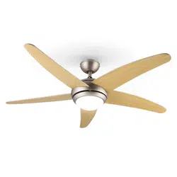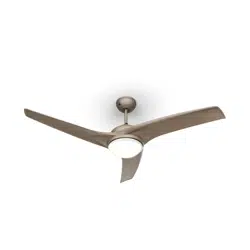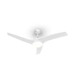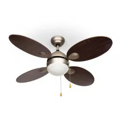
SKY BREEZE
SMART
Deckenventilator
Ceiling Fan
Ventilateur de plafond
Ventilador de techo
Ventilatore a sotto
www.klarstein.com
10047037 10047038 10048079 10048080


3
DE
Sehr geehrte Kundin, sehr geehrter Kunde,
wir gratulieren Ihnen zum Erwerb Ihres Geräts. Lesen Sie
die folgende Anleitung sorgfältig durch und befolgen Sie
sie, um mögliche Schäden zu vermeiden. Für Schäden, die
durch Nichtbeachtung der Anleitung und unsachgemäßen
Gebrauch entstehen, übernehmen wir keine Haftung.
Scannen Sie den QR-Code, um Zugriff auf die aktuellste
Bedienungsanleitung und weitere Informationen rund um
das Produkt zu erhalten.
INHALT
TECHNISCHE DATEN
Artikelnummer 10047037, 10047038, 10048079, 10048080
Stromversorgung 220–240 V ~ 50 Hz
Ventilator-Leistung 27 W
Lampentyp LED 16 W dimmbar
Farbtemeperatur 3000 K, 4000 K, 6500 K
Farbwiedergabeindex (CRI) ≥80 Ra
Maximaler Volumenstrom 170 m
3
/min
Frequenzband
Maximale Sendeleistung
433 MHz
10 dBm
Dieses Produkt enthält eine Lichtquelle der Energieezienzklasse E.
Sicherheitshinweise 4
Lieferumfang 5
Übersicht 7
Installation 8
Zusammenbau 10
Gerätesteuerung über das Smartphone 16
Reinigung und Pege 18
Fehlersuche und Fehlerbehebung 18
Spezielle Entsorgungshinweise für Verbraucher in Deutschland 19
Hinweise zur Entsorgung 21
Konformitätserklärung 21
English 23
Español 41
Français 59
Italiano 77

4
DE
SICHERHEITSHINWEISE
• Befestigen Sie den Ventilator niemals an einer Steckdose, sondern direkt an
der Decke.
• Der Mindestabstand zwischen den Flügeln des Ventilators und dem Boden
muss mehr als 2,3 m betragen. Die Tragfähigkeit des Hakens, an dem der
Ventilator aufgehängt wird, muss mindestens 100 kg betragen.
• Achten Sie darauf, dass Sie in der Zuleitung zum Deckenventilator einen
allpoligen Trennschalter mit einem Kontaktabstand von mindestens 3 mm
zwischen den Polen installieren.
• Alle Verkabelungen müssen den örtlichen und nationalen Vorschriften
entsprechen. Wenn Sie mit der Verkabelung nicht vertraut sind, wenden Sie
sich an einen qualizierten Elektriker.
• Um einen möglichen Stromschlag zu vermeiden, schalten Sie vor der
Installation des Ventilators den Strom ab, indem Sie die Sicherungen im
Sicherungskasten und den zugehörigen Wandschalter ausschalten. Wenn Sie
die Sicherungsschalter nicht in der Aus-Stellung verriegeln können, bringen
Sie eine auffällige Warnvorrichtung, z. B. ein Schild, an der Schalttafel an.
• Das Modell oder die Typenbezeichnung von Leuchtmitteln, die in Ventilatoren
eingebaut werden können, die für diesen Zweck vorgesehen sind.
• Schalten Sie das Gerät vor dem Anschließen aus.
• Die elektrische Verkabelung muss den örtlichen Vorschriften entsprechen.
• Der Ventilator muss ordnungsgemäß geerdet sein, um das Risiko eines
Stromschlags zu vermeiden.
• Montieren Sie den Ventilator niemals in einem feuchten oder nassen Raum.
• Seien Sie vorsichtig, wenn Sie in der Nähe der rotierenden Flügel arbeiten.
• Um die Gefahr von Verletzungen zu verringern, befestigen Sie den Ventilator
gemäß dieser Anleitung direkt an der Tragkonstruktion des Gebäudes und
verwenden Sie nur die mitgelieferten Teile.
• Dieses Gerät kann von Kindern ab 8 Jahren sowie von Personen mit
verringerten körperlichen, sensorischen oder mentalen Fähigkeiten oder
Mangel an Erfahrung und Wissen benutzt werden, wenn sie beaufsichtigt
oder bezüglich des sicheren Gebrauchs des Geräts angeleitet wurden und die
damit verbundenen Gefahren verstehen.
• Um das Risiko eines Brandes, eines Stromschlags oder eines Motorschadens
zu verringern, verwenden Sie keinen Halbleiter-Drehzahlregler mit diesem
Ventilator. Verwenden Sie nur Antriebe mit variabler Geschwindigkeit.
• Kinder sollten beaufsichtigt werden, damit sie nicht mit dem Gerät spielen.
• Vergewissern Sie sich, dass das Gebläse vom Stromnetz getrennt ist, bevor Sie
die Schutzvorrichtung entfernen.
• Treffen Sie Vorkehrungen, um das Zurückströmen von Gasen aus dem offenen
Schornstein von Gas- oder anderen brennstoffbetriebenen Geräten in den
Raum zu vermeiden (bei Kanal- und Trennwandventilatoren).
Hinweis: Lassen Sie den Ventilator immer von jemandem installieren, der sich
mit elektrischer Verkabelung auskennt.

5
DE
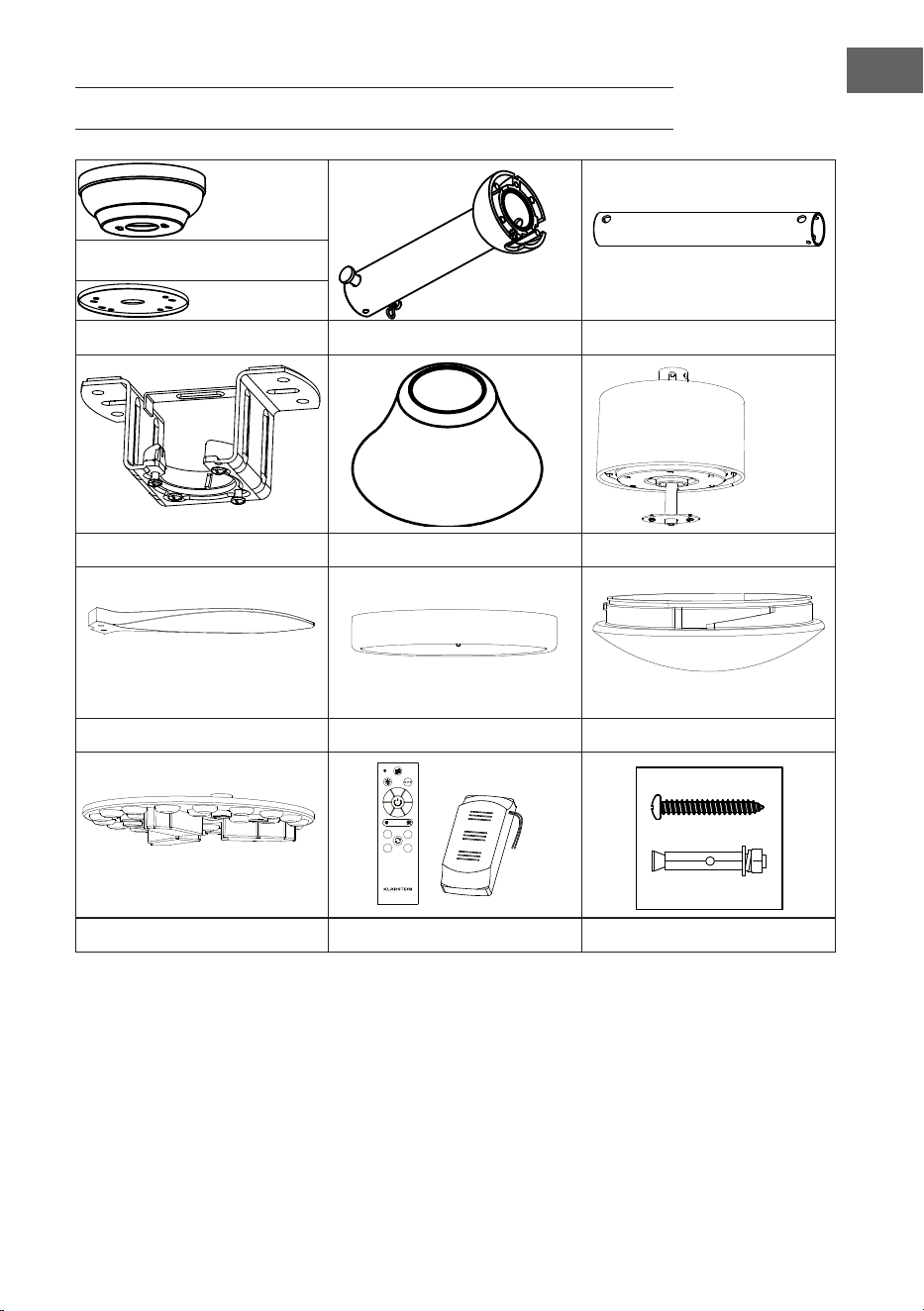
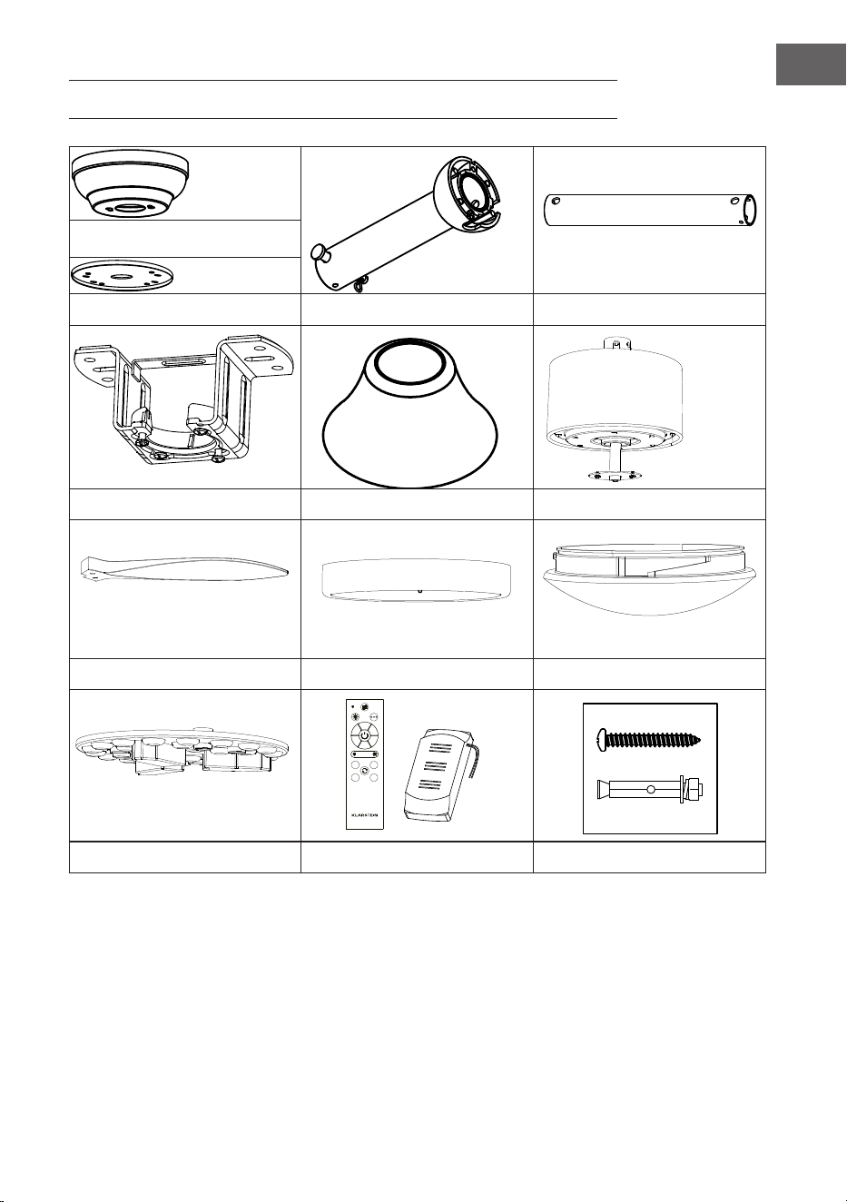
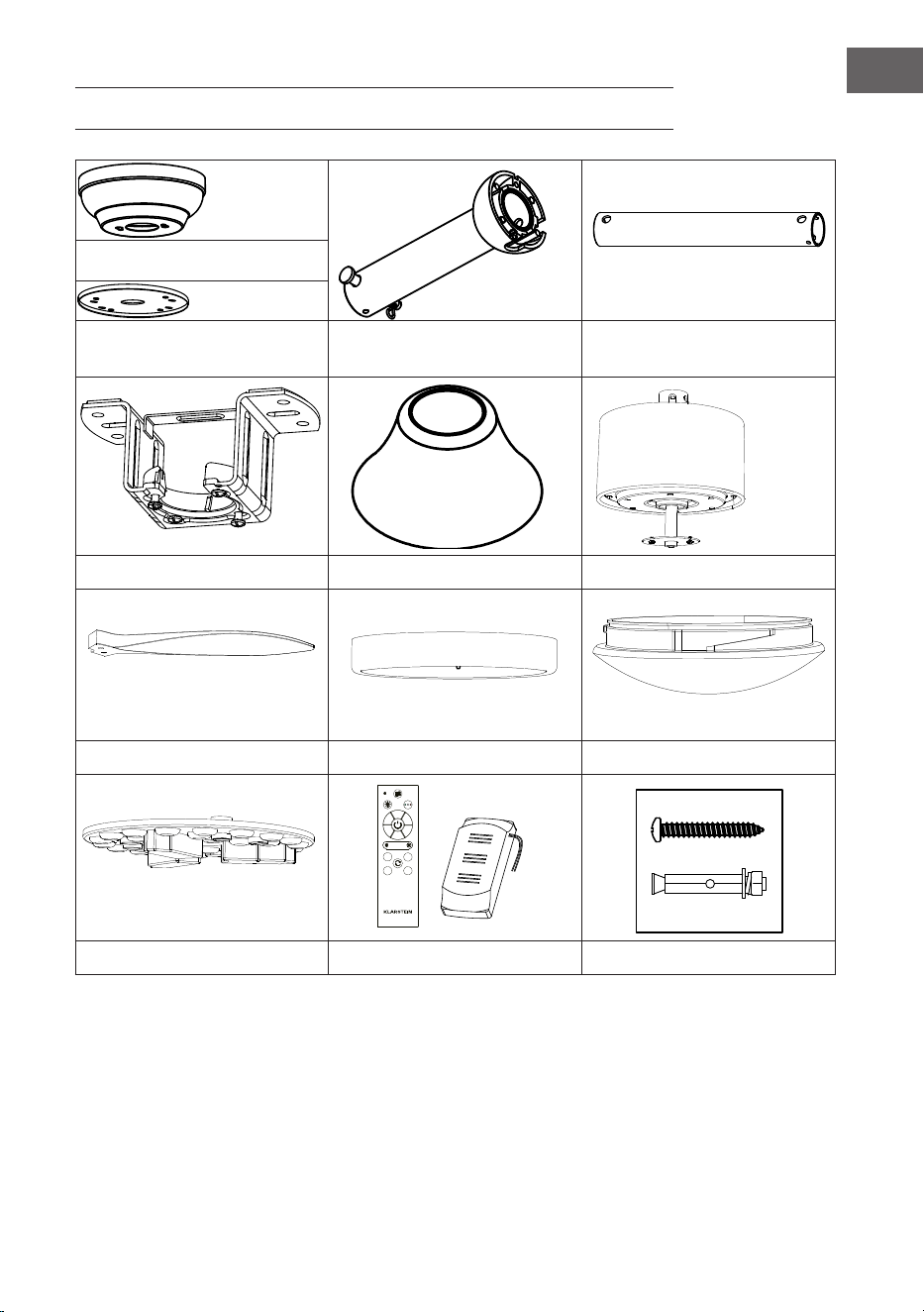
LIEFERUMFANG
Abdeckung
Wasserdichte Abdeckung Deckenstange und Hängekugel Deckenstange
Befestigungsklammer Dekorative Abdeckungen Motor
Flügel Lampenrahmen Lampenschirm
3
2
1
4
5
6
1H
2H
4H
8H
LED-Lichtquelle Fernbedienung Schraubenpackung

6
DE
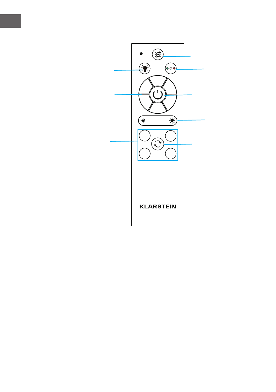
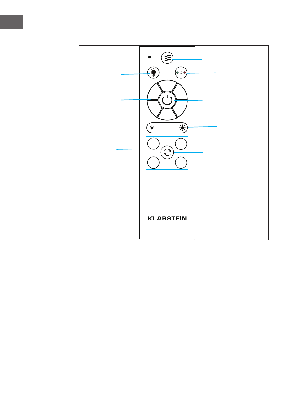
Fernbedienung
3
2
1
4
5
6
1H
2H
4H
8H
Lichttemperatur kühl
- warm
Ein/Aus
Natürlicher Wind
Licht ein/aus
Ventiltorgeschwindigkeit
Drehrichtung
Timer
1 Stunde
2 Stunden
4 Stunden
8 Stunden
Lichtstärke
7
DE
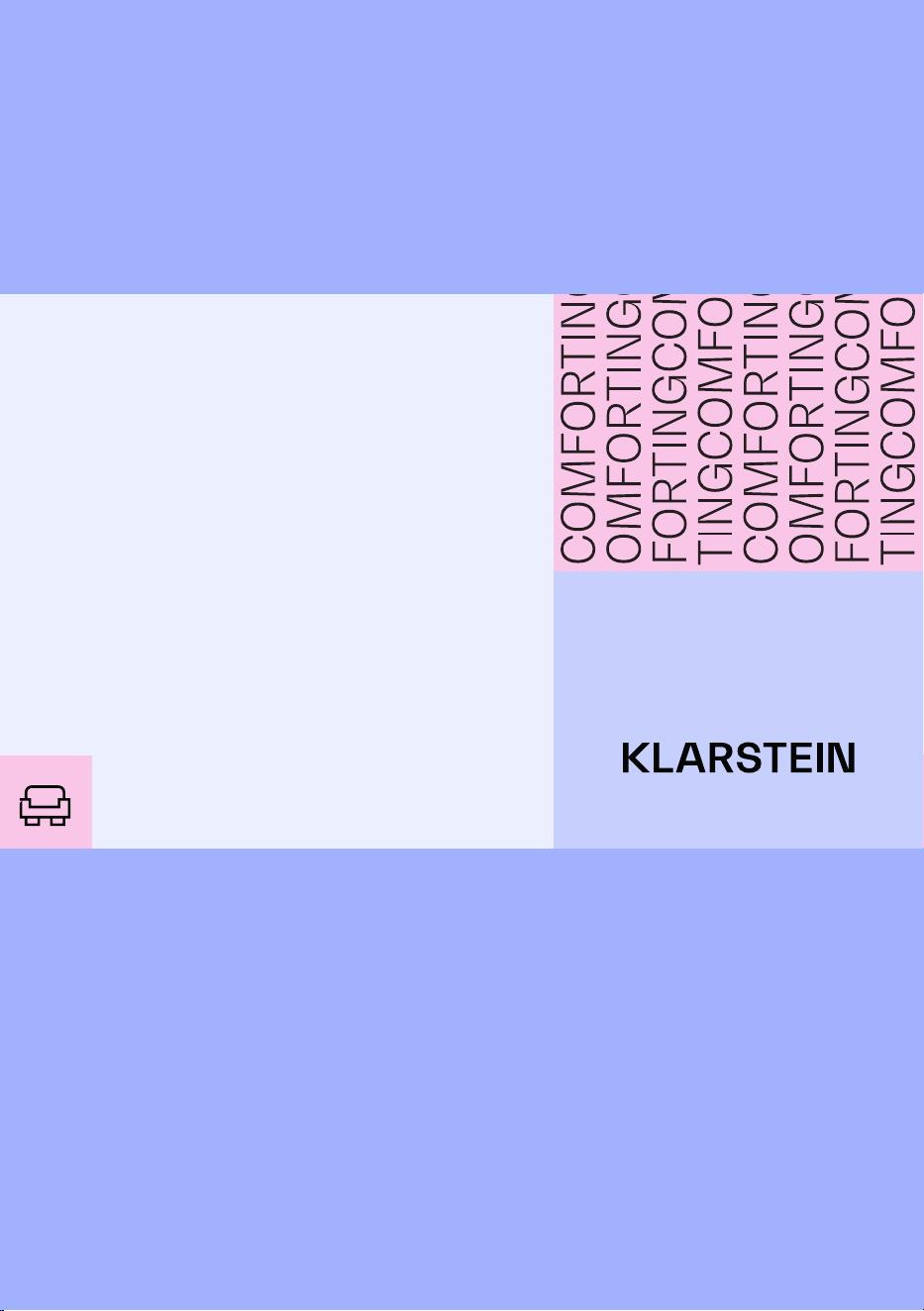
ÜBERSICHT
1
Mounting Brsacket
2
Remonte Control Receiver
11
LED
7
3
4
5
6
8
10
12
9
Fan Blade
R Pin
Pin
Downrod
Decorative cover
Canopy
Fan Boby
Metal Base
Lamp Shade
Befestigungshalterung
Abdeckung
R Stift
Deckenstange
Dekorative Abdeckung
Ventilatorgehäuse
Sockel aus Metall
Stift
Lampenschirm
LED
Ventilatorügel
Fernbedienungsempfänger
8
DE
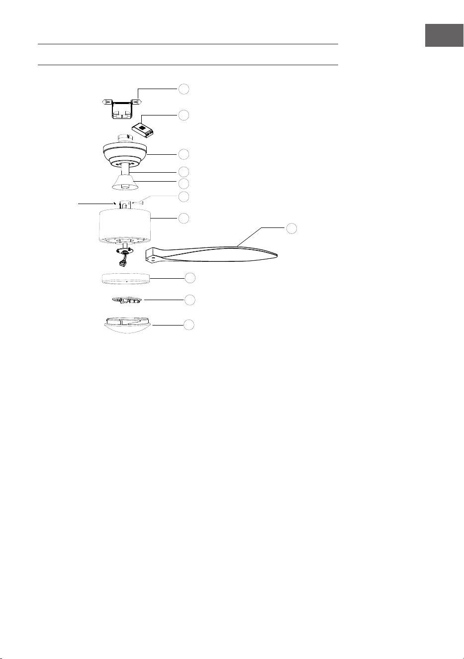
INSTALLATION
Installationsvorbereitung
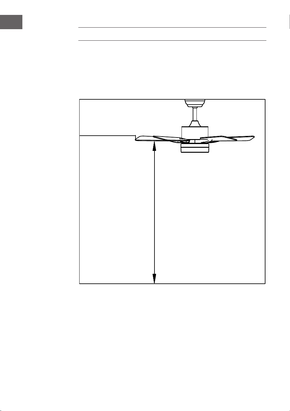
Um Verletzungen und Schäden zu vermeiden, stellen Sie sicher, dass die Flügel in
einem Abstand von 2,3 m vom Boden und 76 cm von Wänden oder Hindernissen
aufgehängt werden können. Vergewissern Sie sich, dass der Anschlusskasten
sicher an der Gebäudestruktur befestigt ist und das volle Gewicht des Ventilators
tragen kann.
Für die Installation sind folgende Werkzeuge erforderlich
Schraubenzieher, Schlitzschraubendreher, verstellbare Zange oder
Schraubenschlüssel, Trittleiter, Drahtschneider und Isolierband.
76 cm von der
Wand oder dem
nächstgelegenen
Hindernis
2,3 m von den
Flügeln bis zum
Boden

9
DE
Den Installationsort des Ventilators vorbereiten
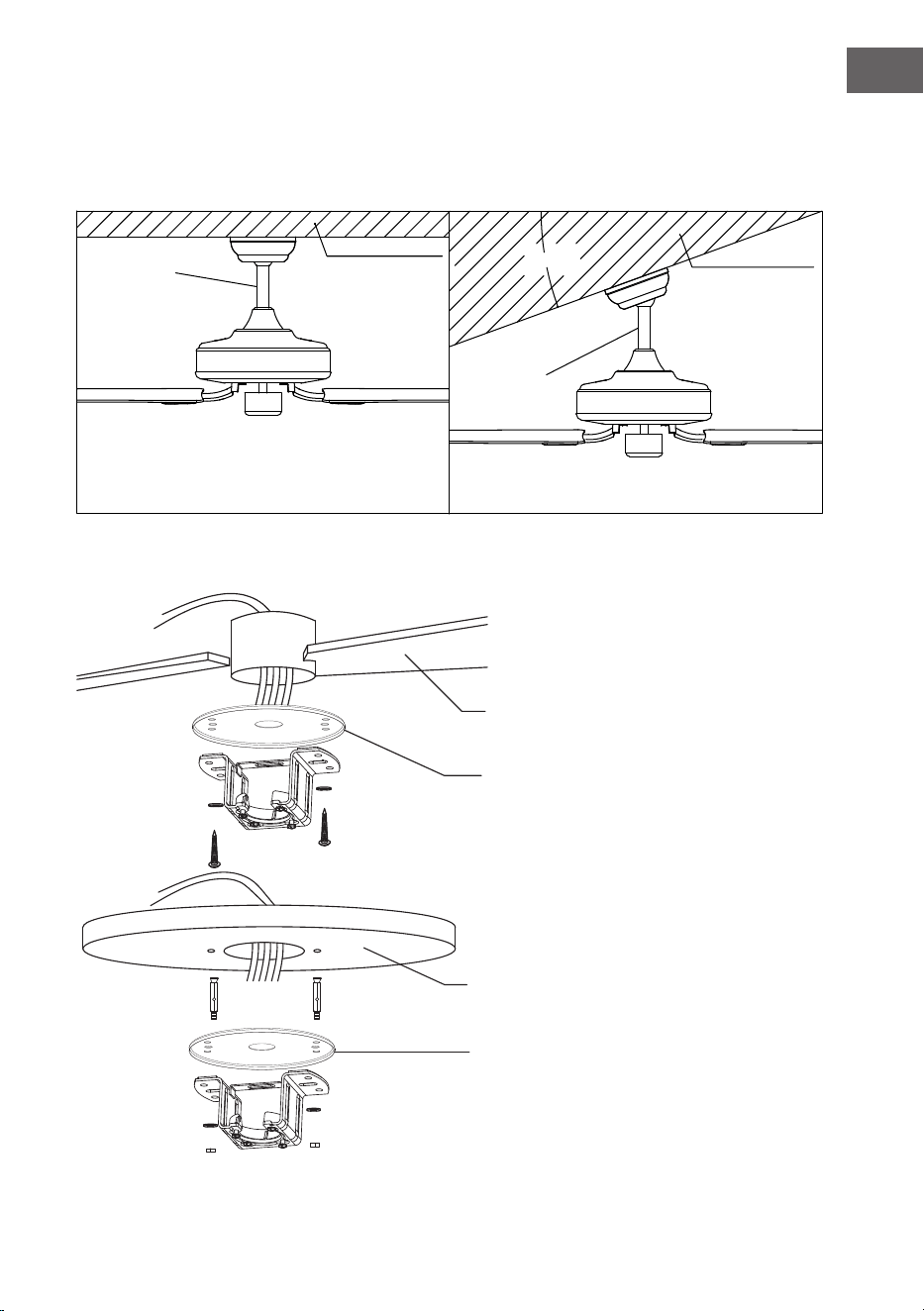
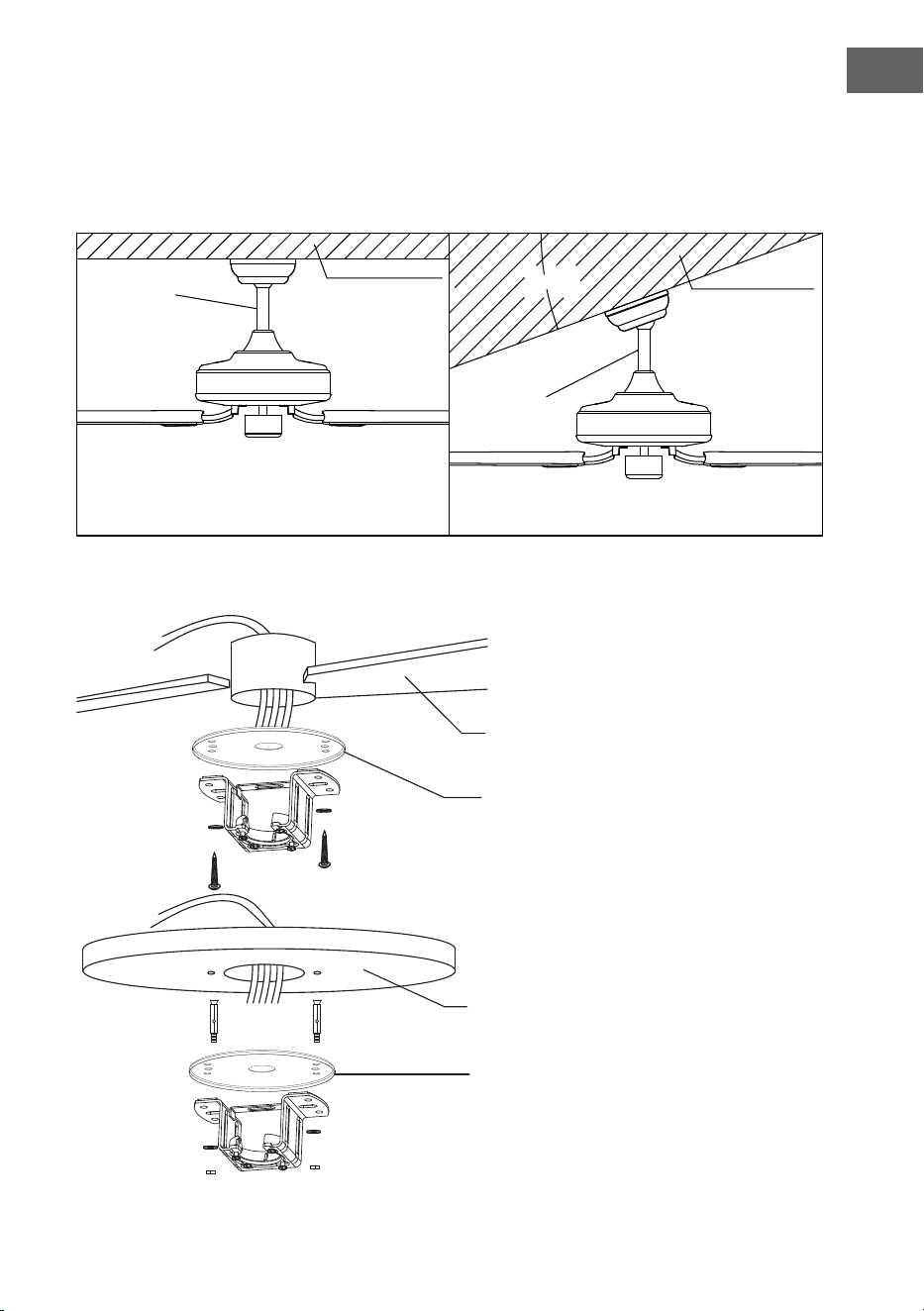
Dieser Ventilator kann mit einer Deckenstange an einer normalen oder gewölbten
Decke montiert werden. Die Aufhängelänge kann durch Verwendung einer
längeren Deckenstange vergrößert werden.
20°
Anbringen der Befestigungsklammer
Standard-
Montage
Stützstrebe
Stützstrebe
Schräge
Montage
Die Standardmontage hängt mit einer
Deckenstange von der Decke
Bei einer gewölbten oder schrägen Decken wird
eine schräge Montage empfohlen
Holzdecke
Betondecke
Bohren Sie ein Loch von Ø mm in die Betondecke
und setzen Sie die Schrauben ein. Richten Sie die
Halterung an der Bohrung aus und ziehen Sie die
Mutter fest.
Wasserdichte Abdeckung
Wasserdichte Abdeckung
10
DE
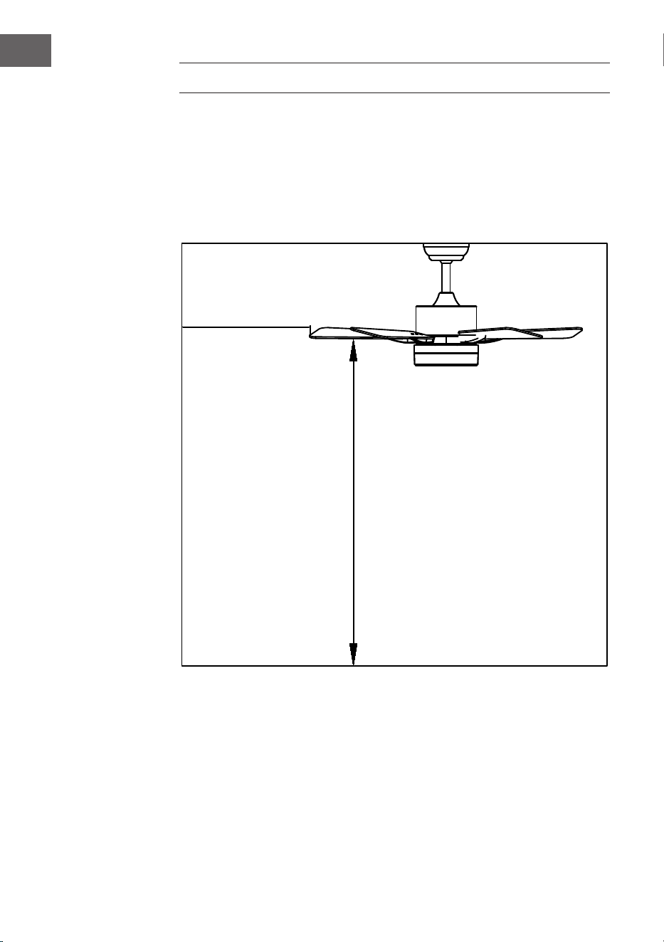
ZUSAMMENBAU
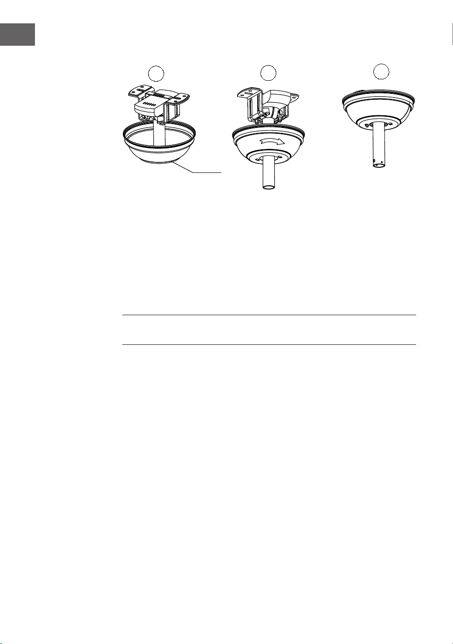
Zusammenbau und Aufhängung des Ventilators
• Wenn Sie die Aufhängung Ihres Ventilators verlängern möchten, müssen Sie
die Aufhängekugel von der mitgelieferten 6"-Stange entfernen, um sie mit
einer längeren Stange (im Lieferumfang enthalten) zu verwenden (wenn Sie
die 6"-Stange verwenden möchten, folgen Sie bitte den Anweisungen unten).
• Um die Aufhängekugel zu entfernen, lösen Sie die Stellschraube an der
Aufhängekugel und entfernen Sie den Stift und den Clip. Schieben Sie die
Hängekugel nach unten und entfernen Sie den Anschlagstift. Schieben Sie
die Hängekugel von der ursprünglichen Stange A und schieben Sie sie an der
längeren Stange B hinunter (beachten Sie, dass die Stange oben ein Loch für
die Stellschraube hat; verwenden Sie dieses Loch, wenn Sie die Stellschraube
einstellen).
• Stecken Sie den Anschlagstift in das obere Ende der längeren Deckenstange
und schieben Sie die Aufhängekugel nach oben.
• Vergewissern Sie sich, dass der Anschlagstift mit den Schlitzen an
der Innenseite der Aufhängekugel übereinstimmt, und ziehen Sie die
Stellschraube fest an.
Hinweis: Um das Durchführen der elektrischen Drähte durch die Deckenstange
vorzubereiten, kleben Sie ein kleines Stück Isolierband an die Enden der
elektrischen Drähte - so werden die Drähte zusammengehalten, wenn sie durch
die Stange geführt werden.
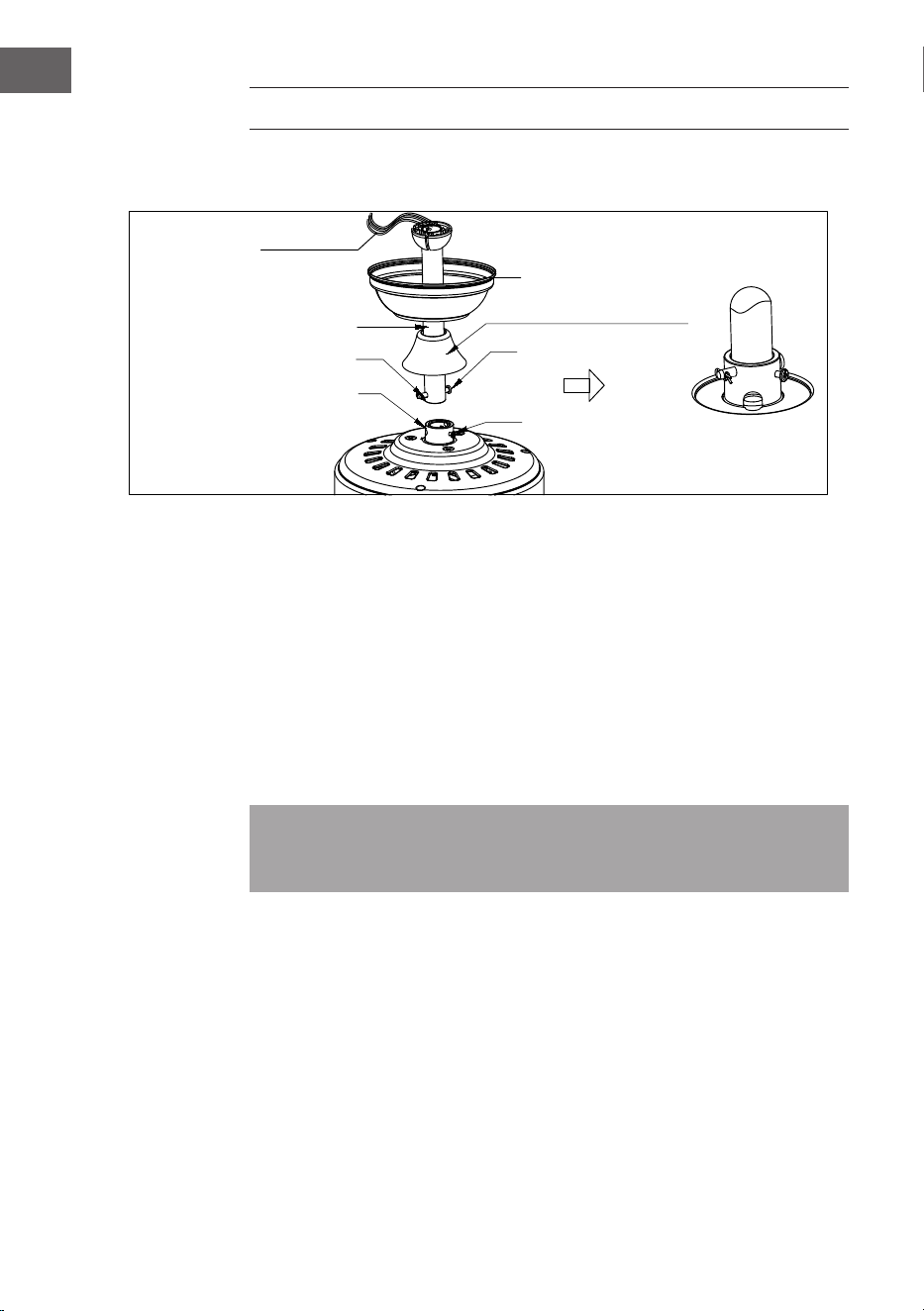
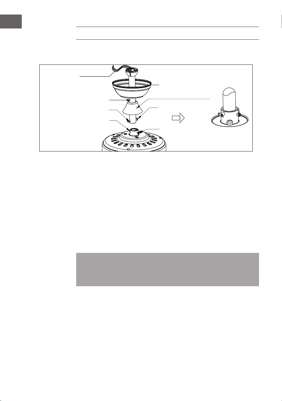
• Lösen Sie die Bügel-Stellschraube und die Mutter oben am Motorgehäuse.
Entfernen Sie den Stift und die Klammer von der Deckenstange (falls noch
nicht geschehen). Schieben Sie die Deckenstange durch die Abdeckung.
• Fädeln Sie die elektrischen Drähte durch die Deckenstange und entfernen Sie
die überschüssige Kabellänge von der Oberseite der Deckenstange.
• Führen Sie die Deckenstange in den Bügel des Motorgehäuses ein und setzen
Sie den Stift und die Klammer, die zuvor entfernt wurden, wieder ein. Ziehen
Sie die Bügel-Gewindestifte und die Mutter fest an.
• Schieben Sie die Abdeckung auf das Motorgehäuse herunter.
Elektrische
Verkabelung
Schlitz für
Aufhängkugel
R-Clip
Adapter
Abdeckung
Dekorative Abdeckungen
Durchgangsklemme
Bügel-Stellschraube

11
DE
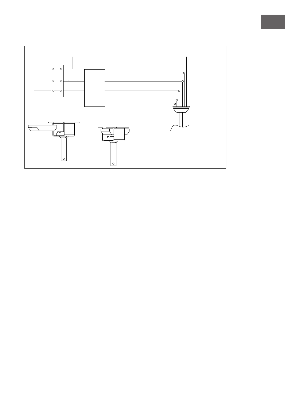
Anschluss für die Fernbedienung
green/yellow stripe
Light L
(blue)
Neutral N(White)
Ground
wire
N
L
L
Remote
control
receiver
input N
(Black)
(white)
Grey DC motor L
Pink DC motor L
Red DC motor L
Receiver place:
DC:
grün/gelb gestreift
Grau DC-Motor L
Rosa DC-Motor L
Rot DC-Motor L
Platzierung Empfänger
Eingang N
(blau)
L
(schwarz)
Erdungs-
Licht L blau
Neutral N (weiß)
leiter

12
DE
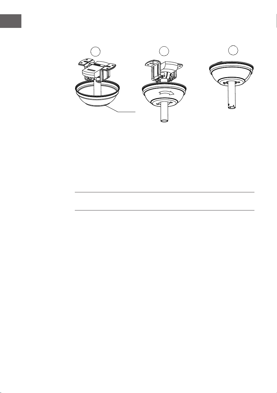
Zusammenbau Abdeckung
2
3
1
Heben Sie die Abdeckung bis zur Aufhängung an und richten Sie dabei die
gelösten Schrauben in der Aufhängung an den Langlöchern in der Abdeckung aus.
Drehen Sie die Kabinenhaube zum Verriegeln. Setzen Sie die Schrauben wieder ein
und sichern Sie alle Schrauben mit einem Schraubendreher.
Wenn die Aufhängevorrichtung an der Steckdose befestigt ist und den Ventilator
tragen kann, können Sie den Ventilator nun aufhängen. Fassen Sie den Ventilator
fest mit beiden Händen an. Schieben Sie die Stange durch die Öffnung in der
Aufhängung und lassen Sie die Kugel der Aufhängung auf der Aufhängung
ruhen. Drehen Sie den Schlitz in der Aufhängekugel, bis er mit der Lasche an der
Aufhängevorrichtung übereinstimmt.
Hinweis: Lassen Sie sich von einer anderen Person helfen, die die Trittleiter
festhält und den Ventilator zu Ihnen hochhebt, sobald Sie auf der Leiter stehen.
Abdeckung
ok
13
DE
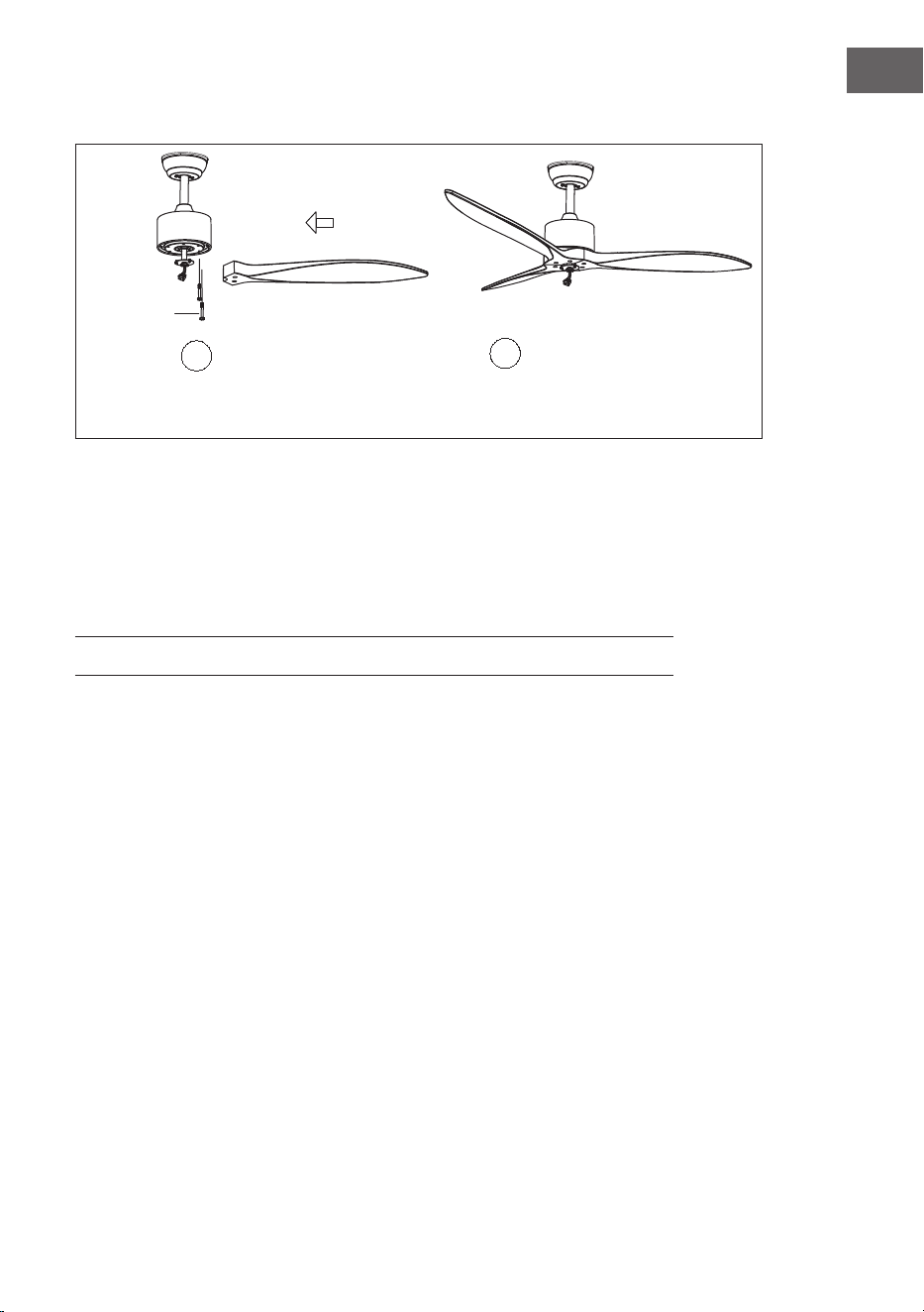
Montage der Rotorblätter
1
2
Zeitersparnis: Die Unterlegscheiben für die Rotorblattschrauben können an
jeder Rotorblattschraube angebracht werden, bevor die Rotorblätter angebracht
werden.
Richten Sie die Löcher für die Klingen auf die Löcher für die Motorschrauben aus
und ziehen Sie alle Schrauben fest, wenn alle Blätter montiert sind. Wiederholen
Sie diesen Vorgang mit den übrigen Blatthalterungen, bevor Sie die Schrauben
endgültig befestigen.
Hinweis: Ziehen Sie die Rotorblattschrauben zweimal an.
ok
Schraube
14
DE
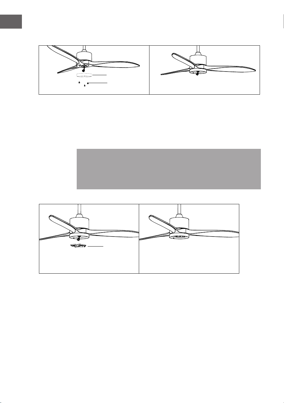
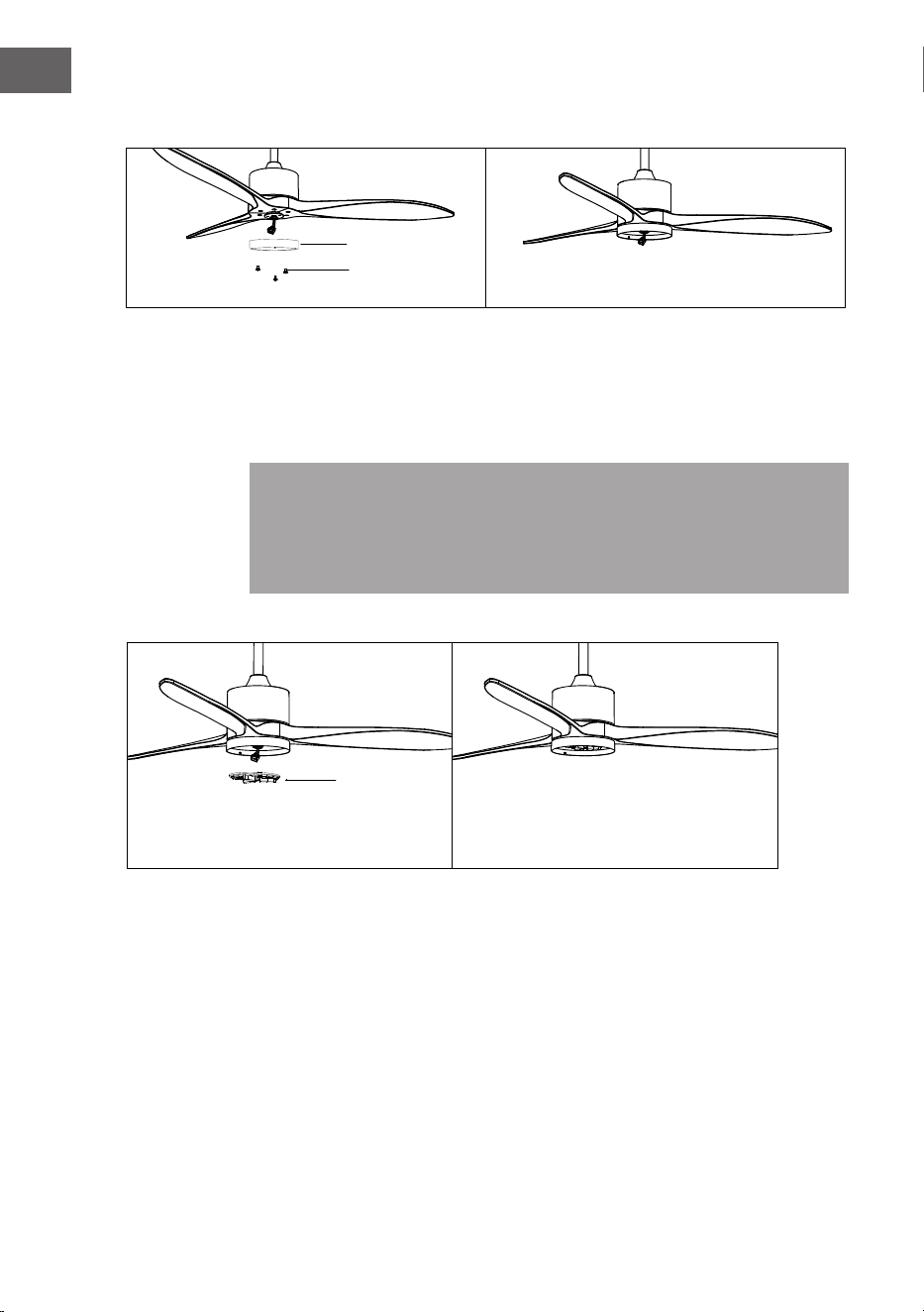
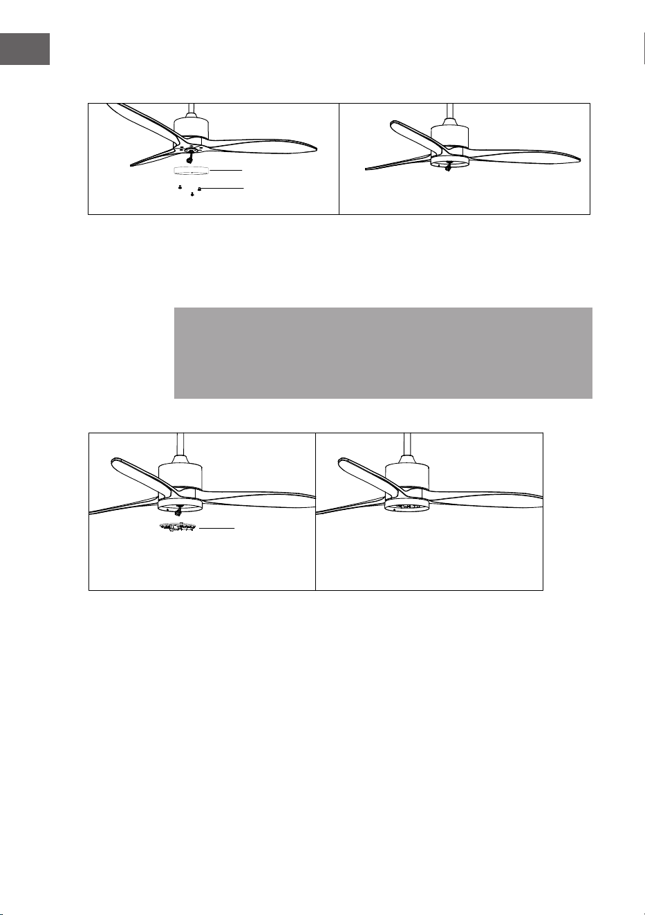
Zusammenbau LED-Rahmen
• Lösen Sie eine Stallschraube.
• Befestigen Sie den LED-Rahmen an der Unterseite des Ventilators, indem Sie
die beiden anderen Stellschrauben in die Schlitze einführen, drehen Sie sie in
die richtige Position, sichern Sie dann die vorherige Stellschraube, indem Sie
das Schraubenloch mit dem Loch an der Unterseite des Ventilators ausrichten,
und ziehen Sie die verbleibenden beiden Stellschrauben an, um den LED-
Rahmen zu xieren.
Hinweis: Beschädigen Sie beim Ein- und Ausbau des LED-Rahmens die
Isolierpads nicht. Wenn Sie die Stellschrauben zu stark oder zu schnell anziehen,
werden die Isolierpads beschädigt. Lassen Sie sich von einer anderen Person
helfen, die die Leiter festhält, und Ihnen den Ventilator anreicht, wenn Sie auf
der Leiter stehen.
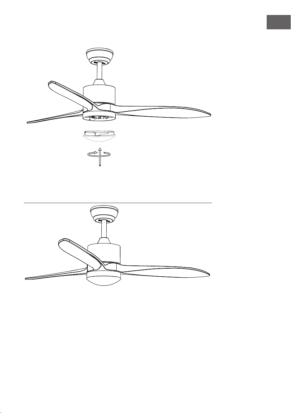
Montage des Lampenschirms
Bringen Sie die Abdeckung und den Lampenschirm wieder an der LED-Rahmen an.
LED
ok
Lampen-Rahmen
Schrauben

15
DE
Montage des dekorativen Rahmens
Bringen Sie die Abdeckung und den Lampenschirm wieder am LED-Rahmen an
und befestigen Sie sie mit Zierklammern und Schraubenmuttern.

16
DE
DEVICE CONTROL BY SMARTPHONE
If you integrate the device into your home WiFi, you can conveniently operate it via
the associated Klarstein app. The app not only allows you to remotely control the
device via your smartphone, but also gives you access to recipes and additional
information.
Follow these steps to connect your smartphone to your Klarstein device:
1. Download the Klarstein app rst by scanning the QR code with your
smartphone (see below), or download it directly from App Store or Google
Play.
2. Make sure your smartphone is connected to the same WiFi network that your
Klarstein device is to be connected to.
3. Open the Klarstein app.
4. Sign in to your account. If you do not have an account, sign up in the Klarstein
app.
5. Follow the instructions from the app.
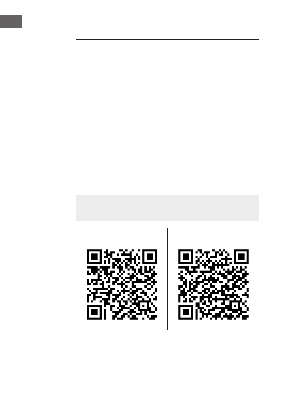
App Download
Use the scan function of your smartphone to scan the QR code and save the app on
your smartphone.
Note: The app provides further information on how to use the app and help on
how to connect to your device as soon as you open it for the rst time.
iOS Android

17
DE
Fehlerbehebung bei Verbindungsproblemen
Wenn Ihr Klarstein-Gerät im WLAN nicht gefunden werden kann, überprüfen Sie
Folgendes:
1. Das Gerät ist nicht eingesteckt. Stellen Sie sicher, dass Ihr Gerät an eine
Steckdose angeschlossen ist.
2. Das Gerät bendet sich nicht im Kopplungsmodus. Vergewissern Sie sich, dass
die WLAN-Anzeige (LED) auf dem Bedienfeld Ihres Smart-Gerätes blinkt, wie
in der Anweisung „WLAN-Einstellungen zurücksetzen“ Ihres Smart-Gerätes
beschrieben (Anweisungen zum Verbindungsprozess des Gerätes sind in der
Regel verfügbar).
3. Der WLAN-Zugangspunkt arbeitet nicht auf 5 GHz. Vergewissern Sie sich,
dass Ihr Zugangspunkt auf 2,4-GHz-Band arbeitet und Sie eine separate
SSID auf 2,4-GHz-Band haben. Wenn Sie sich nicht sicher sind, in welchem
Frequenzbereich Ihr Zugangspunkt arbeitet, wenden Sie sich an Ihren
Internetanbieter.
Wichtig: Beachten Sie, dass, wenn Ihr WLAN-Router über ein Dualband
verfügt – also sowohl im 2,4-GHz- als auch im 5-GHz-Band arbeitet –, Sie
die SSIDs für jedes Band trennen und die 2,4-GHz-SSID für die Verbindung
verwenden müssen.
4. Die Firewall-Einstellung Ihres WLAN-Netzwerks erlaubt der Klarstein-App
möglicherweise nicht, die WLAN-Einstellungen auf Ihrem Smart-Gerät zu
kongurieren. Stellen Sie sicher, dass Sie kein öffentliches WLAN-Netzwerk
nutzen, z. B. von Flughäfen, Wohnheimen, Firmen usw.
5. Unterschiedliche Anmeldeinformationen auf dem Smartphone und in der
App. Vergewissern Sie sich, dass die in der Klarstein-App eingegebenen
WLAN-Anmeldedaten mit denen übereinstimmen, mit denen Ihr Smartphone
verbunden ist.
Wenn Sie die oben genannten Punkte befolgt haben und Ihr Smart-Gerät sich
immer noch nicht mit der App verbinden kann, wenden Sie sich per E-Mail an
uns, um Unterstützung zu erhalten:
18
DE
REINIGUNG UND PFLEGE
• Trennen Sie das Gerät immer vom Stromnetz, bevor Sie das Gerät reinigen
oder Wartungsarbeiten durchführen.
• Verwenden Sie zur Reinigung des Geräts niemals einen nassen Schwamm.
• Um das Produkt nicht zu beschädigen, empehlt es sich, geeignete Mittel
für die empndlichen Oberächen und Produkte zu verwenden, die die
Abnutzung des Geräts verlangsamen.
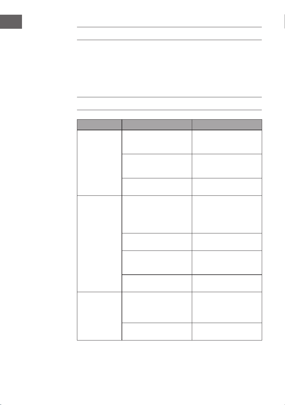
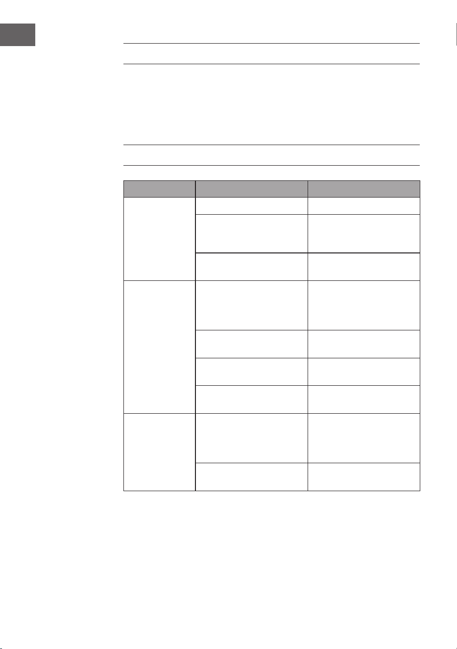
FEHLERSUCHE UND FEHLERBEHEBUNG
Problem Mögliche Ursache Ansatz
Der Ventilator
läuft nicht.
Sicherung oder
Sicherungsschalter
durchgebrannt.
Prüfen Sie Ihre Sicherungen.
Lose Kabelverbindungen. Überprüfen Sie alle
Verbindungen auf lose
Kabel.
Die Geschwindigkeit wurde
nicht korrekt eingestellt.
Wählen Sie eine
Geschwindigkeit.
Der Ventilator
macht
Geräusche.
Die obere Kappe berührt die
Decke.
Achten Sie darauf, dass
zwischen der oberen
Kappe und der Decke ein
Mindestabstand von 3 mm
besteht.
Die Schrauben der
Rotorblätter sind lose.
Ziehen Sie alle Schrauben
an.
Der Deckenventilator ist
nicht richtig an der Decke
befestigt.
Ziehen Sie alle Schrauben in
der Aufhängeplatte fest.
Die Geschwindigkeit ist nicht
richtig eingestellt.
Wählen Sie eine
Geschwindigkeit.
Der Ventilator
wackelt.
Die Rotorblätter sind nicht
waagerecht zur Decke
ausgerichtet.
Stellen Sie den Ventilator
so ein, dass sich alle Flügel
auf gleicher Höhe zur Decke
benden.
Die Schrauben der
Rotorblätter sind lose.
Ziehen Sie alle Schrauben
an.
19
DE
SPEZIELLE ENTSORGUNGSHINWEISE FÜR
VERBRAUCHER IN DEUTSCHLAND
Entsorgen Sie Ihre Altgeräte fachgerecht. Dadurch wird gewährleistet, dass die
Altgeräte umweltgerecht verwertet und negative Auswirkungen auf die Umwelt
und menschliche Gesundheit vermieden werden. Bei der Entsorgung sind
folgende Regeln zu beachten:
• Jeder Verbraucher ist gesetzlich verpichtet, Elektro- und
Elektronikaltgeräte (Altgeräte) sowie Batterien und Akkus
getrennt vom Hausmüll zu entsorgen. Sie erkennen die
entsprechenden Altgeräte durch folgendes Symbol der
durchgestrichenen Mülltonne (WEEE-Symbol).
• Sie haben Altbatterien und Altakkumulatoren, die nicht vom Altgerät
umschlossen sind, sowie Lampen, die zerstörungsfrei aus dem Altgerät
entnommen werden können, vor der Abgabe an einer Entsorgungsstelle vom
Altgerät zerstörungsfrei zu trennen.
• Bestimmte Lampen und Leuchtmittel fallen ebenso unter das Elektro- und
Elektronikgesetz und sind dementsprechend wie Altgeräte zu behandeln.
Ausgenommen sind Glühbirnen und Halogenlampen. Entsorgen Sie
Glühbirnen und Halogenlampen bitte über den Hausmüll, sofern sie nicht das
WEEE-Symbol tragen.
• Jeder Verbraucher ist für das Löschen von personenbezogenen Daten auf dem
Elektro- bzw. Elektronikgerät selbst verantwortlich.
Rücknahmepicht der Vertreiber
Vertreiber mit einer Verkaufsäche für Elektro- und Elektronikgeräte von
mindestens 400 Quadratmetern sowie Vertreiber von Lebensmitteln mit einer
Gesamtverkaufsäche von mindestens 800 Quadratmetern, die mehrmals im
Kalenderjahr oder dauerhaft Elektro- und Elektronikgeräte anbieten und auf dem
Markt bereitstellen, sind verpichtet,
1. bei der Abgabe eines neuen Elektro- oder Elektronikgerätes an einen Endnutzer
ein Altgerät des Endnutzers der gleichen Geräteart, das im Wesentlichen die
gleichen Funktionen wie das neue Gerät erfüllt, am Ort der Abgabe oder in
unmittelbarer Nähe hierzu unentgeltlich zurückzunehmen und
2. auf Verlangen des Endnutzers Altgeräte, die in keiner äußeren Abmessung
größer als 25 Zentimeter sind, im Einzelhandelsgeschäft oder in unmittelbarer
Nähe hierzu unentgeltlich zurückzunehmen; die Rücknahme darf nicht an den
Kauf eines Elektro- oder Elektronikgerätes geknüpft werden und ist auf drei
Altgeräte pro Geräteart beschränkt.
20
DE
• Bei einem Vertrieb unter Verwendung von Fernkommunikationsmitteln
ist die unentgeltliche Abholung am Ort der Abgabe auf Elektro- und
Elektronikgeräte der Kategorien 1, 2 und 4 gemäß § 2 Abs. 1 ElektroG, nämlich
„Wärmeüberträger“, „Bildschirmgeräte“ (Oberäche von mehr als 100 cm²)
oder „Großgeräte“ (letztere mit mindestens einer äußeren Abmessung
über 50 Zentimeter) beschränkt. Für andere Elektro- und Elektronikgeräte
(Kategorien 3, 5, 6) ist eine Rückgabemöglichkeit in zumutbarer Entfernung
zum jeweiligen Endnutzer zu gewährleisten.
• Altgeräte dürfen kostenlos auf dem lokalen Wertstoffhof oder in folgenden
Sammelstellen in Ihrer Nähe abgegeben werden: www.take-e-back.de
• Für Elektro- und Elektronikgeräte der Kategorien 1, 2 und 4 bieten wir auch die
Möglichkeit einer unentgeltlichen Abholung am Ort der Abgabe. Beim Kauf
eines Neugeräts haben Sie die Möglichkeit, eine Altgerätabholung über die
Webseite auszuwählen.
• Batterien können überall dort kostenfrei zurückgegeben werden, wo sie
verkauft werden (z. B. Super-, Bau-, Drogeriemarkt). Auch Wertstoff- und
Recyclinghöfe nehmen Batterien zurück. Sie können Batterien auch per Post
an uns zurücksenden. Altbatterien in haushaltsüblichen Mengen können Sie
direkt bei uns von Montag bis Freitag zwischen 08:00 und 16:00 Uhr unter der
folgenden Adresse unentgeltlich zurückgeben:
Chal-Tec Fulllment GmbH
Norddeutschlandstr. 3
47475 Kamp-Lintfort
• Wichtig zu beachten ist, dass Lithiumbatterien aus Sicherheitsgründen vor der
Rückgabe gegen Kurzschluss gesichert werden müssen (z. B. durch Abkleben
der Pole).
• Finden sich unter der durchgestrichenen Mülltonne auf der Batterie zusätzlich
die Zeichen Cd, Hg oder Pb ist das ein Hinweis darauf, dass die Batterie
gefährliche Schadstoffe enthält (»Cd« steht für Cadmium, »Pb« für Blei und
»Hg« für Quecksilber).
Hinweis zur Abfallvermeidung
Indem Sie die Lebensdauer Ihrer Altgeräte verlängern, tragen Sie dazu bei,
Ressourcen ezient zu nutzen und zusätzlichen Müll zu vermeiden. Die
Lebensdauer Ihrer Altgeräte können Sie verlängern, indem Sie defekte Altgeräte
reparieren lassen. Wenn sich Ihr Altgerät in gutem Zustand bendet, könnten Sie
es spenden, verschenken oder verkaufen.
21
DE
HINWEISE ZUR ENTSORGUNG
Wenn es in Ihrem Land eine gesetzliche Regelung
zur Entsorgung von elektrischen und elektronischen
Geräten gibt, weist dieses Symbol auf dem Produkt oder
auf der Verpackung darauf hin, dass dieses Produkt
nicht im Hausmüll entsorgt werden darf. Stattdessen
muss es zu einer Sammelstelle für das Recycling von
elektrischen und elektronischen Geräten gebracht
werden. Durch regelkonforme Entsorgung schützen
Sie die Umwelt und die Gesundheit Ihrer Mitmenschen
vor negativen Konsequenzen. Informationen zum
Recycling und zur Entsorgung dieses Produkts,
erhalten Sie von Ihrer örtlichen Verwaltung oder Ihrem
Hausmüllentsorgungsdienst.
Dieses Produkt enthält Batterien. Wenn es in Ihrem
Land eine gesetzliche Regelung zur Entsorgung von
Batterien gibt, dürfen die Batterien nicht im Hausmüll
entsorgt werden. Informieren Sie sich über die örtlichen
Bestimmungen zur Entsorgung von Batterien. Durch
regelkonforme Entsorgung schützen Sie die Umwelt
und die Gesundheit Ihrer Mitmenschen vor negativen
Konsequenzen.
KONFORMITÄTSERKLÄRUNG
Hersteller:
Chal-Tec GmbH, Mühlenstraße 25, 10243 Berlin
Kontakt: [email protected]
Hiermit erklärt Chal-Tec GmbH, dass der Funkanlagentyp
Sky Breeze Smart der Richtlinie 2014/53/EU entspricht.
Der vollständige Text der EU-Konformitätserklärung ist
unter der folgenden Internetadresse verfügbar: use.
berlin/10047037
22
DE
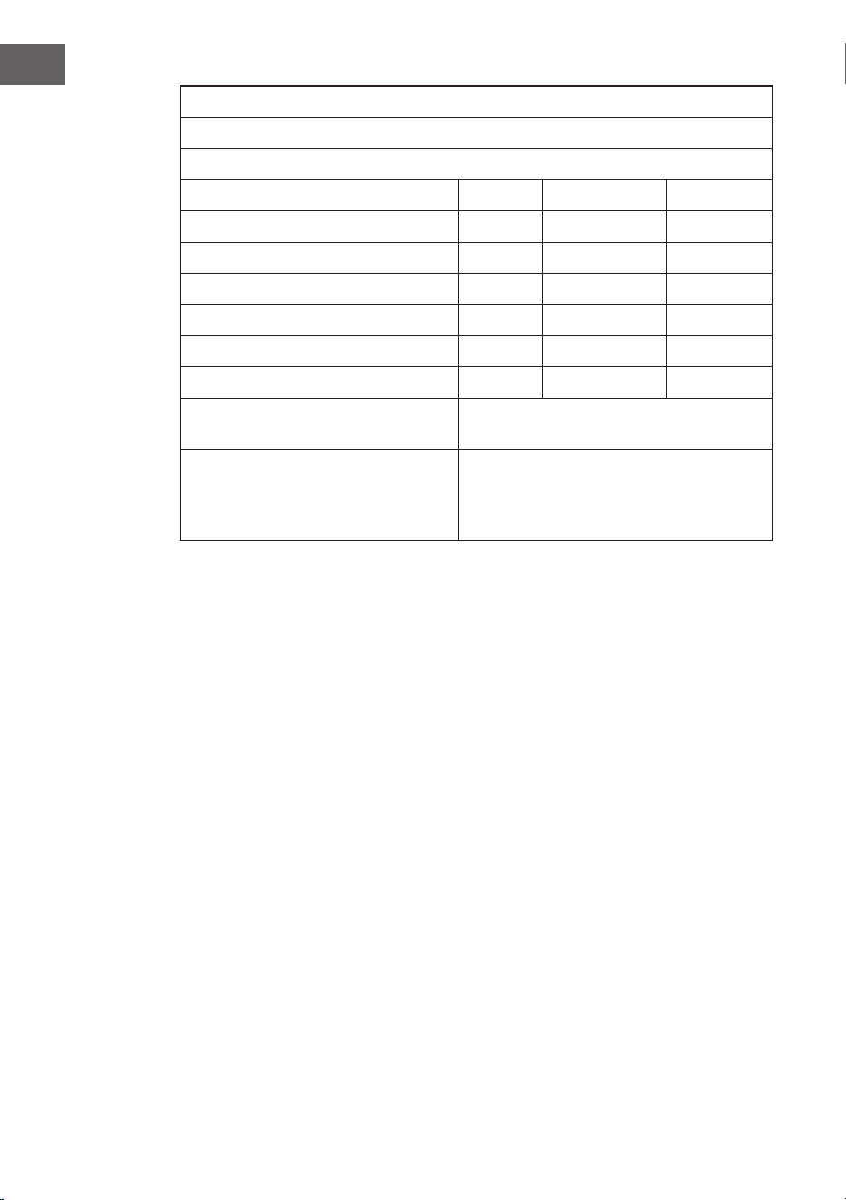
Produktinformationsanforderungen nach VERORDNUNG (EU) Nr. 206/2012
Informationen zur Angabe des Modells/der Modelle, auf das/die sich die
Informationen beziehen:
10047037, 10047038, 10048079, 10048080 Klarstein SkyBreeze Smart
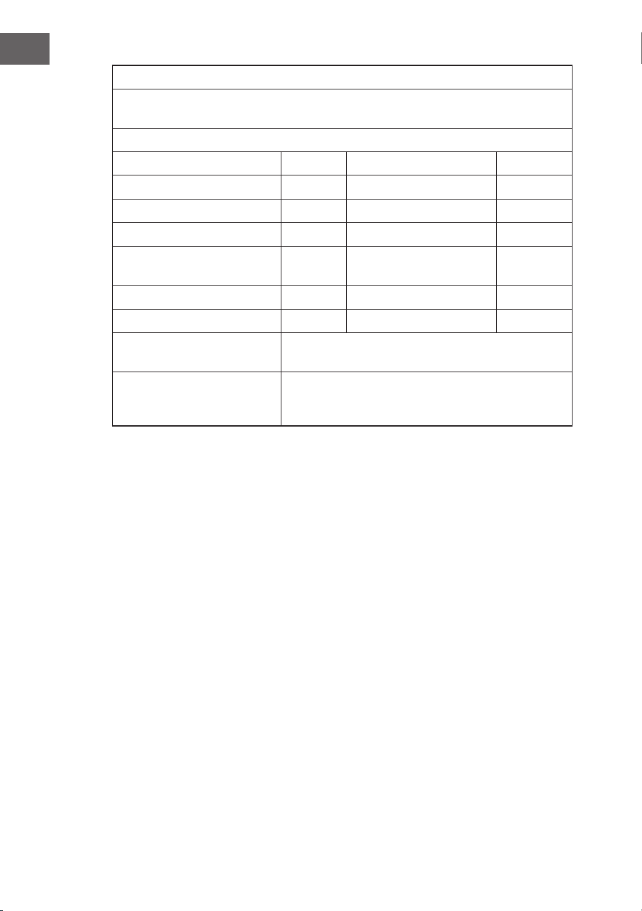
Bezeichnung Symbol Wert Einheit
Maximaler Volumenstrom F 169,6 m3/min
Ventilator-Leistungsaufnahme P 26,8 W
Serviceverhältnis SV 3,3 (m3/min)/W
Leistungsaufnahme im
Bereitschaftszustand
PSB 0,45 W
Ventilator-Schallleistungspege LWA <45 dB dB(A)
Maximale Luftgeschwindigkeit c 2,5 m/s
Messnorm für die Ermittlung
des Serviceverhältnisses
IEC 60879:2019
Kontaktadresse für weitere
Informationen
Chal-Tec GmbH Mühlenstraße 25 10243 Berlin
Deutschland

23
EN
Dear Customer,
Congratulations on purchasing this device. Please read the
following instructions carefully and follow them to prevent
possible damages. We assume no liability for damage
caused by disregard of the instructions and improper use.
Scan the QR code to get access to the latest user manual
and more product information.
CONTENTS
TECHNICAL DATA
Item number 10047037, 10047038, 10048079, 10048080
Power supply 220-240 V~ 50 Hz
Fan power 27 W
Lamp type LED 16 W dimmable
Colour temperature 3000 K, 4000 K, 6500 K
Colour Rendering Index (CRI) ≥80 Ra
Maximum volume ow 170 m
3
/min
Frequency band
maximum radio-frequency power
433 MHz
10 dBm
This product contains a light source of energy eciency class E.
Safety Instructions 24
Scope of delivery 25
Overview 27
Installation 28
Assembly 30
Device Control by Smartphone 36
Cleaning and Care 38
Troubleshooting 38
Disposal Considerations 39
Declaration of Conformity 39

24
EN
SAFETY INSTRUCTIONS
• Never attach the fan to a power point,but to the ceiling itself.
• The minimum distance between the blades of the fan and the oor must be
more than 2.3 m. The minimum carrying capacity of the hook from which the
fan is hung must be 100 kg.
• Make sure to install all poles disconnection switch having a contact separation
of at least 3 mm between poles in the supply wiring to the ceiling fan.
• All wiring must comply with national and local electrical codes. If you are
unfamiliar with wiring, consult a qualied electrician.
• To avoid possible electric shock, before installing your fan, disconnect the
power by turning off the circuit breakers to the fuse box and associated wall
switch location. If you cannot lock the circuit breakers in the off position,
securely attach a conspicuous warning device, such as a sign, to the service
panel.
• The model or type reference of luminaries which may be installed in fans
which are constructed for his purpose.
• Switch off the power before connecting.
• The electrical wiring must be in accordance with the local regulation.
• The fan must be properly earthed to avoid the risk of electric shocks.
• Never mount the fan in a moist or wet room.
• Be careful when working near the rotating blades.
• To reduce the risk of personal injury, secure the fan directly to the building’s
support structure according to these instructions and use only the hardware
supplied.
• This device may be only used by children 8 years old or older and persons with
limited physical, sensory and mental capabilities and / or lack of experience
and knowledge, provided that they have been instructed in use of the device
by a responsible person who understands the associated risks.
• To reduce the risk of re, electric shock or motor damage, do not use a solid-
state speed controller with this fan. Use only variable speed drives.
• Children being supervised not to play with the appliance.
• Ensure that the fan is switched off from the supply mains before removing the
guard.
• Take precautions to avoid the back-ow of gases into the room from the open
ue of gas or other fuel-burning appliances (for duct and partition fans).
Note: Always have your fan installed by someone who is knowledgeable about
electrical wiring.
25
EN
SCOPE OF DELIVERY
Canopy
Waterproof sleeve Downrod and hanging ball Downrod
Hanger bracket Decorative covers Motor
Blade Lamp panel Lamp shade
3
2
1
4
5
6
1H
2H
4H
8H
LED light source Remote control Spiral package

26
EN
Remote control
3
2
1
4
5
6
1H
2H
4H
8H
light temperature
cool – warm
on/off
natural wind
light on/off
fan speed
spinning direction
Timer
1 hour
2 hours
4 hours
8 hours
light strength

27
EN
OVERVIEW
1
Mounting Brsacket
2
Remonte Control Receiver
11
LED
7
3
4
5
6
8
10
12
9
Fan Blade
R Pin
Pin
Downrod
Decorative cover
Canopy
Fan Boby
Metal Base
Lamp Shade
mounting bracket
canopy
R Pin
Downrod
decorative cover
Fan body
Metal base
pin
Lamp shade
LED
Fan blade
Remote control receiver

28
EN
INSTALLATION
Installation Preparation
To prevent personal injury and damage, ensure that the hanging location allows
the blades to be 2.3 m from the oor and 76 cm from any wall or obstruction.
Ensure that the junction box is securely attached to the building structure and can
support the full weight of the fan.
Installation requires these tools
Screwdriver, at head screwdriver, adjustable pliers or wrench, stepladder, wire
cutters and electrical tape.
76 cm from
wall or nearest
obstruction
2.3 m from the
blades to the
oor
29
EN
Preparing the fan site
This fan can be mounted on a normal or vaulted ceiling using a down rod. The
hanging length can be increased by using a longer down rod.
20°
Installing the hanger bracket
Standard
Mounting
Style
Support brace
Support brace
Angled
Mounting
Style
Standard mounting hangs from the ceiling by a
down rod
Angled mounting recommended for a vaulted or
angled ceiling
Wood ceiling
Concrete ceiling
Drill a Ø 8 mm hole in the concrete ceiling and insert
the bolt. Align the bracket with the hole and tighten
the nut.
Waterproof sleeve
Waterproof sleeve
30
EN
ASSEMBLY
Assembling and hanging the fan
• If you wish to extend the hanging length of your fan, you will need to remove
the hanging ball from the supplied 6“ down rod to use with an extended
down rod (supplied) (if you wish to use the 6“ down rod, please follow the
instructions below).
• To remove the hanging ball, loosen the set screw on the hanging ball and
remove the pin and clip. Lower the hanging ball and remove the stop pin.
Slide the hanging ball off the original down rod A and slide it down the longer
down rod B (note that the top of the down rod has a set screw hole; use this
hole when adjusting the set screw).
• Insert the stop pin into the top of the extended down rod and lift the hanging
ball.
• Ensure the stop pin aligns with the slots on the inside of the hanging ball and
tighten the set screw securely.
Note: To prepare for threading electrical wires through the down rod, apply a
small piece of electrical tape to the ends of the electrical wires - this will hold the
wires together when threaded through the down rod.
• Loosen the yoke setscrews and nut at the top of the motor housing. Remove
the pin and clip from the downrod (if you have not already done so). Slide the
downrod through the canopy.
• Thread the electrical wires through the downrod and remove any excess wire
slack from the top of the downrod.
• Insert the down rod into the motor housing yoke and re-insert the pin and clip
that were previously removed. Tighten the yoke setscrews and nut securely.
• Lower the canopy onto the motor housing.
electrical
wiring
hanging
ball slot
R-Clip
Adapter
Canopy
Decorative covers
through clip
yoke set screw

31
EN
Remote control connection
green/yellow stripe
Light L
(blue)
Neutral N(White)
Ground
wire
N
L
L
Remote
control
receiver
input N
(Black)
(white)
Grey DC motor L
Pink DC motor L
Red DC motor L
Receiver place:
DC:
green/ yellow stripe
Grey DC motor L
Pink DC motor L
Red DC motor L
Receiver place
input N
(blue)
L
(black)
Ground
Light L blue
Neutral N (white)
wire
32
EN
Canopy Assembly
2
3
1
Lift the canopy up to the hanger bracket, aligning the loosened screws in the
hanger bracket with the slotted holes in the canopy. Turn canopy to lock. Re-insert
screws and secure all screws with screwdriver.
With the hanging bracket secured to the outlet box and able to support the fan,
you are now ready to hang your fan. Grasp the fan rmly with both hands. Slide
the down rod through the opening in the hanger bracket and allow the hanger
ball to rest on the hanger bracket. Turn the slot in the hanger ball until it aligns
with the tab on the hanger bracket.
Note: Get help from another person to hold the stepladder in place and lift the fan
up to you once you are on the ladder.
Canopy
ok

33
EN
Blade assembly
1
2
Time saving: Washers for blade screws can be tted to each blade screw before
the blades are tted.
Align blade holes with motor screw holes and tighten all screws when all blades
are tted. Repeat with the remaining blade arms before permanently securing the
screws.
Note: Tighten blade screws twice.
ok
Screw

34
EN
LED Pan Assembly
• Unscrew one set screw.
• Attach the LED panel to the bottom of the fan by inserting the other two set-
screw heads into the keyhole slots, turn it into place, then secure the previous
set-screw by aligning the screw hole and the hole on the bottom of the fan,
tighten the remaining two set-screws to secure the LED panel
Note: When installing or removing the LED panel, please keep the insulation
pads intact. Tightening the set screws too much or too fast will damage the
insulation pads. Use the help of another person to hold the stepladder in place
and lift the fan towards you once you are on the ladder.
Lamp Shade Assembly
Restore the cover and the lamp shade bacl to the LED pan.
LED
ok
Lamp panel
Screws

35
EN
Decorative Pan Assembly
Restore the cover and the lamp shade back to the LED pan and secure them with
decorative clips and bolt nuts.

36
EN
DEVICE CONTROL BY SMARTPHONE
If you integrate the device into your home WiFi, you can conveniently operate it via
the associated Klarstein app. The app not only allows you to remotely control the
device via your smartphone, but also gives you access to recipes and additional
information.
Follow these steps to connect your smartphone to your Klarstein device:
1. Download the Klarstein app rst by scanning the QR code with your
smartphone (see below), or download it directly from App Store or Google
Play.
2. Make sure your smartphone is connected to the same WiFi network that your
Klarstein device is to be connected to.
3. Open the Klarstein app.
4. Sign in to your account. If you do not have an account, sign up in the Klarstein
app.
5. Follow the instructions from the app.
App Download
Use the scan function of your smartphone to scan the QR code and save the app on
your smartphone.
Note: The app provides further information on how to use the app and help on
how to connect to your device as soon as you open it for the rst time.
iOS Android

37
EN
Troubleshooting connection problems
If your Klarstein device cannot be found in the WLAN, check the following:
1. The device is not plugged in. Make sure that your device is plugged into an
electric socket.
2. The device is not in pairing mode. Make sure that the WiFi indicator (LED)
on the smart device control panel is blinking as described in the ‘Reset WiFi
settings‘ instruction of your smart device (instructions are usually available on
device connection process).
3. The WiFi access point does not operate on 5 GHz. Make sure that your access
point operates on 2.4 GHz band and you have a separate SSID on 2.4 GHz
band. If you are not sure about the operating band of your access point,
please contact your internet provider company.
Important: please note that if your WiFi router is dual band - operating on both
2.4 GHz and 5 GHz band - you need to separate the SSIDs for each band and use
the 2.4 GHz SSID for connection.
4. Firewall settings of your WiFi network; the rewall setting of your WiFi network
may not allow the Klarstein app to congure the WiFi settings on your smart
device. Please make sure that you are not using a public WiFi network, e.g.
airports, dormitories, companies, etc.
5. Different credentials used in smartphone and the app. Make sure that the WiFi
credentials entered in the Klarstein app are the same as the ones that your
smartphone is connected to.
Following the above mentioned points, if your smart device still fails to connect
to the app, please contact us via email for support:
38
EN
CLEANING AND CARE
• Always disconnect the appliance from the power supply before cleaning the
appliance or carrying out maintenance work.
• Never use a wet sponge to clean the appliance.
• In order not to damage the product, it is advisable to use equipment adapted
to the sensitive surfaces and products, which will slow down the wear of the
device.
TROUBLESHOOTING
Problem Possible cause Approach
The fan does not
start.
Fuse or circuit breaker
blown.
Check your fuses.
Loose cable connections. Check all connections for
loose cables.
Speed was not set correctly. Select a speed.
The fan makes
noise.
The upper cap touches the
ceiling.
Make sure there is a
minimum distance of 3 mm
between the top cap and the
ceiling.
Screws of rotor blades are
loose.
Tighten all screws.
Ceiling fan is not properly
attached to the ceiling.
Tighten all screws in the
suspension plate.
Speed is not adjusted
correctly.
Select a speed.
The fan is
wobbling.
Rotor blades are not
adjusted horizontally to the
ceiling.
Move the fan so that all
blades are at the same
height to the ceiling.
Screws of the rotor blades
are loose.
Tighten all screws.
39
EN
DISPOSAL CONSIDERATIONS
If there is a legal regulation for the disposal of electrical
and electronic devices in your country, this symbol on the
product or on the packaging indicates that this product
must not be disposed of with household waste. Instead,
it must be taken to a collection point for the recycling
of electrical and electronic equipment. By disposing of
it in accordance with the rules, you are protecting the
environment and the health of your fellow human beings
from negative consequences. For information about the
recycling and disposal of this product, please contact your
local authority or your household waste disposal service.
This product contains batteries. If there is a legal regulation
for the disposal of batteries in your country, the batteries must
not be disposed of with household waste. Find out about local
regulations for disposing of batteries. By disposing of them in
accordance with the rules, you are protecting the environment
and the health of your fellow human beings from negative
consequences.
DECLARATION OF CONFORMITY
Manufacturer & Importer for Great Britain:
Chal-Tec GmbH, Mühlenstrasse 25, 10243 Berlin, Germany.
Contact: [email protected]
Hereby, Chal-Tec GmbH declares that the radio equipment
type Sky Breeze Smart is in compliance with Directive 2014/53/
EU. The full text of the EU declaration of conformity is available
at the following internet address: use.berlin/10047037
For Great Britain: Hereby, Chal-Tec GmbH declares that the
radio equipment type Sky Breeze Smart is in compliance
with the relevant statutory requirements. The full text of the
declaration of conformity is available at the following internet
address: use.berlin/10047037
40
EN
Product information requirements according to REGULATION (EU) No 206/2012
Information to identify the model(s) to which the information relates to
10047037, 10047038, 10048079, 10048080 Klarstein SkyBreeze Smart
Description Symbol Value Unit
Maximum fan ow rate F 169.6 m3/min
Fan power input P 26.8 W
Service value SV 3,3 (m3/min)/W
Standby power consumption PSB 0.45 W
Fan sound power level LWA <45 dB dB(A)
Maximum air velocity c 2.5 m/s
Measurement standard for service
value
IEC 60879:2019
Contact details for obtaining more
information
Chal-Tec GmbH
Mühlenstraße 25
10243 Berlin
Deutschland

41
ES
Estimado cliente:
Le felicitamos por la adquisición de este producto. Lea
atentamente el siguiente manual y siga cuidadosamente
las instrucciones de uso con el n de evitar posibles daños.
La empresa no se responsabiliza de los daños ocasionados
por un uso indebido del producto o por haber desatendido
las indicaciones de seguridad. Escanee el código QR
para acceder al manual de usuario más reciente y a más
información sobre el producto.
ÍNDICE
DATOS TÉCNICOS
Número de artículo 10047037, 10047038, 10048079, 10048080
Alimentación 220-240 V ~ 50 Hz
Rendimiento del ventilador 27 W
Tipo de lámpara LED 16 W regulable
Temperatura de color 3000 K, 4000 K, 6500 K
Índice de reproducción cromática ≥80 Ra
Caudal máximo 170 m
3/
min
Banda de frecuencia
Potencia máxima de transmisión
433 MHz
10 dBm
Este producto contiene una fuente de luz de clase de eciencia energética E.
Indicaciones de seguridad 42
Volumen de suministro 43
Descripción 45
Instalación 46
Montaje 48
Control del aparato mediante teléfono inteligente 54
Limpieza y cuidado 56
Detección y reparación de anomalías 56
Retirada del aparato 57
Declaración de conformidad 57

42
ES
INDICACIONES DE SEGURIDAD
• No je nunca el ventilador a una toma de corriente, sino al propio techo.
• La distancia mínima entre las aspas del ventilador y el suelo debe ser superior
a 2,3 m. La capacidad de carga mínima del gancho del que cuelga el ventilador
debe ser de 100 kg.
• Asegúrese de instalar un interruptor de desconexión de todos los polos con
una separación de contactos de al menos 3 mm entre polos en el cableado de
alimentación del ventilador de techo.
• Todo el cableado debe cumplir los códigos eléctricos nacionales y locales. Si
no está familiarizado con el cableado, consulte a un electricista cualicado.
• Para evitar posibles descargas eléctricas, antes de instalar su ventilador,
desconecte la corriente apagando los disyuntores de la caja de fusibles y
la ubicación del interruptor de pared asociado. Si no puede bloquear los
disyuntores en la posición de apagado, je un dispositivo de advertencia bien
visible, como un cartel, al panel de servicio.
• El modelo o tipo de referencia de las luminarias que pueden instalarse en los
ventiladores construidos a tal efecto.
• Desconecte la alimentación antes de conectar.
• El cableado eléctrico debe ser conforme a la normativa local.
• El ventilador debe estar correctamente conectado a tierra para evitar el riesgo
de descargas eléctricas.
• Nunca monte el ventilador en una habitación húmeda o mojada.
• Tenga cuidado al trabajar cerca de las aspas giratorias.
• Para reducir el riesgo de lesiones personales, je el ventilador directamente
a la estructura de soporte del edicio de acuerdo con estas instrucciones y
utilice únicamente los herrajes suministrados.
• Los niños mayores de 8 años y las personas con discapacidad física, sensorial
o psíquica, o con falta de experiencia y conocimientos pueden utilizar el
aparato si han sido previamente instruidos por su tutor o supervisor sobre
el funcionamiento del mismo y conocen las funciones, las indicaciones de
seguridad y los riesgos asociados.
• Para reducir el riesgo de incendio, descarga eléctrica o daños en el motor, no
utilice un regulador de velocidad de estado sólido con este ventilador. Utilice
únicamente variadores de velocidad.
• No permita que los niños jueguen con el aparato.
• Asegúrese de que el ventilador está desconectado de la red eléctrica antes de
retirar la protección.
• Tome precauciones para evitar el reujo de gases a la habitación desde el
conducto de humos abierto de aparatos de gas u otros combustibles (para
ventiladores de conductos y tabiques).
Nota: Encargue siempre la instalación de su ventilador a una persona con
conocimientos de cableado eléctrico.
43
ES
VOLUMEN DE SUMINISTRO
Marquesina
Funda impermeable Varilla y bola de techo Barra de techo
Soporte de techo Rosetón decorativo Motor
Aspa Placa de lámpara Pantalla de lámpara
3
2
1
4
5
6
1H
2H
4H
8H
Fuente de luz LED Mando a distancia Kit en espiral
44
ES
Mando a distancia
3
2
1
4
5
6
1H
2H
4H
8H
Temperatura de la luz
fría - cálida
Encendido/apagado
Viento natural
Luz encendida/
apagada
Velocidad del
ventilador
Sentido de giro
Temporizador
1 hora
2 horas
4 horas
8 horas
Potencia de la luz

45
ES
DESCRIPCIÓN
1
Mounting Brsacket
2
Remonte Control Receiver
11
LED
7
3
4
5
6
8
10
12
9
Fan Blade
R Pin
Pin
Downrod
Decorative cover
Canopy
Fan Boby
Metal Base
Lamp Shade
Soporte de montaje
Marquesina
Pasador R
Barra de techo
Rosetón decorativo
Cuerpo del ventilador
Base metálica
Pasador
Pantalla de lámpara
LED
Aspa del ventilador
Receptor del mando a distancia

46
ES
INSTALACIÓN
Preparación de la instalación
Para evitar lesiones personales y daños, asegúrese de que la ubicación para colgar
las aspas permite que estén a 2,3 m del suelo y a 76 cm de cualquier pared u
obstáculo. Asegúrese de que la caja de conexiones esté bien sujeta a la estructura
del edicio y pueda soportar todo el peso del ventilador.
La instalación requiere estas herramientas
Destornillador, destornillador plano, alicates ajustables o llave inglesa, escalera de
mano, cortaalambres y cinta aislante.
76 cm de la pared
o del obstáculo
más cercano
2.3 m de las aspas
al suelo

47
ES
Preparación del lugar de instalación del ventilador
Este ventilador puede montarse en un techo normal o abovedado utilizando una
barra de techo. La longitud de suspensión puede aumentarse utilizando una barra
de techo más larga.
20°
Instalación del soporte de techo
Estilo de
montaje
estándar
Soporte
Soporte
Estilo de
montaje en
ángulo
El montaje estándar cuelga del techo mediante
una barra de techo
El montaje en ángulo está recomendado para
techos abovedados o en ángulo
Techo de madera
Techo de hormigón
Taladre un agujero de Ø 8 mm en el techo de
hormigón e inserte el perno. Alinee el soporte con el
oricio y apriete la tuerca.
Funda impermeable
Funda impermeable
48
ES
MONTAJE
Montar y colgar el ventilador
• Si desea ampliar la longitud de colgado de su ventilador, deberá retirar la
bola de la varilla de techo de 6" suministrada para utilizarla con una varilla de
techo más larga (suministrada) (si desea utilizar la varilla de techo de 6", siga
las instrucciones que se indican a continuación).
• Para retirar la bola de techo, aoje el tornillo de jación de la bola de techo y
retire el pasador y la abrazadera. Baje la bola de techo y retire el pasador de
tope. Deslice la bola de techo fuera de la varilla de techo original A y deslícela
por la varilla de techo más larga B (tenga en cuenta que la parte superior de
la varilla de techo tiene un oricio para el tornillo de ajuste; utilice este oricio
cuando ajuste el tornillo de ajuste).
• Inserte el pasador de tope en la parte superior de la varilla de techo más larga
y levante la bola de techo.
• Asegúrese de que el pasador de tope se alinea con las ranuras del interior de
la bola de techo y apriete bien el tornillo de jación.
Nota: Para preparar el paso de los cables eléctricos a través de la barra de
techo, aplique un pequeño trozo de cinta aislante a los extremos de los cables
eléctricos; esto mantendrá unidos los cables cuando se pasen a través de la
barra de techo.
• Aoje los tornillos de jación del yugo y la tuerca en la parte superior de la
carcasa del motor. Retire el pasador y la abrazadera de la barra de techo (si
aún no lo ha hecho). Deslice la barra de techo a través de la marquesina.
• Pase los cables eléctricos a través de la barra de techo y retire cualquier
exceso de cable ojo de la parte superior de la barra de techo.
• Inserte la barra de techo en el yugo de la carcasa del motor y vuelva a insertar
el pasador y la abrazadera que retiró anteriormente. Apriete rmemente los
tornillos de jación del yugo y la tuerca.
• Baje la marquesina sobre la carcasa del motor.
Cableado
eléctrico
Ranura para
bola de techo
Abrazadera R
Adaptador
Marquesina
Rosetones decorativos
A través de abrazadera
Tornillo de jación del
yugo

49
ES
Conexión del mando a distancia
green/yellow stripe
Light L
(blue)
Neutral N(White)
Ground
wire
N
L
L
Remote
control
receiver
input N
(Black)
(white)
Grey DC motor L
Pink DC motor L
Red DC motor L
Receiver place:
DC:
Raya verde/amarilla
Motor CC gris L
Motor CC rosa L
Motor CC rojo L
Lugar del receptor
Entrada N
(azul)
L
(negro)
Cable
Azul claro L
Neutro N (blanco)
de tierra

50
ES
Montaje de la marquesina
2
3
1
Levante la capota hasta el soporte de suspensión, alineando los tornillos aojados
del soporte de suspensión con los oricios ranurados de la capota. Gire la capota
para bloquearla. Vuelva a insertar los tornillos y asegure todos los tornillos con un
destornillador.
Con el soporte para colgar jado a la caja de salida y capaz de soportar el
ventilador, ya está listo para colgar su ventilador. Sujete rmemente el ventilador
con ambas manos. Deslice la varilla de bajada a través de la abertura del soporte
de suspensión y deje que la bola de suspensión descanse sobre el soporte de
suspensión. Gire la ranura de la bola de suspensión hasta que se alinee con la
lengüeta del soporte de suspensión.
Nota: Pida ayuda a otra persona para que sujete la escalera de mano y le levante
el ventilador una vez que esté en la escalera.
Marquesina
ok

51
ES
Montaje de las aspas
1
2
Ahorro de tiempo: Las arandelas para los tornillos de las cuchillas pueden
colocarse en cada tornillo de las cuchillas antes de montarlas.
Alinee los oricios de las cuchillas con los oricios de los tornillos del motor y
apriete todos los tornillos cuando todas las cuchillas estén colocadas. Repita la
operación con los brazos de las cuchillas restantes antes de jar denitivamente
los tornillos.
Nota: Apriete dos veces los tornillos de las aspas.
ok
Tornillo
52
ES
Montaje del panel LED
• Desenrosque un tornillo.
• Fije el panel de LED a la parte inferior del ventilador insertando las otras dos
cabezas de tornillos de jación en las ranuras de ojo de cerradura, gírelo en
su lugar, luego asegure el tornillo de jación anterior alineando el oricio del
tornillo y el oricio en la parte inferior del ventilador, ajuste los dos tornillos
de jación restantes para asegurar el panel de LED
Nota: Al instalar o retirar el panel LED, mantenga intactas las almohadillas
aislantes. Si se aprietan demasiado o demasiado rápido los tornillos de jación,
se dañarán las almohadillas aislantes. Utilice la ayuda de otra persona para
sujetar la escalera de tijera y levante el ventilador hacia usted una vez que esté
en la escalera.
Montaje de la pantalla de lámpara
Recolocar la cubierta y la pantalla de lámpara en el panel LED
LED
ok
Panel de la lámpara
Tornillos
53
ES
Montaje del panel decorativo
Vuelva a colocar la cubierta y la pantalla de lámpara en el panel LED y fíjelas con
abrazaderas decorativas y tuercas para tornillos.
54
ES
DEVICE CONTROL BY SMARTPHONE
If you integrate the device into your home WiFi, you can conveniently operate it via
the associated Klarstein app. The app not only allows you to remotely control the
device via your smartphone, but also gives you access to recipes and additional
information.
Follow these steps to connect your smartphone to your Klarstein device:
1. Download the Klarstein app rst by scanning the QR code with your
smartphone (see below), or download it directly from App Store or Google
Play.
2. Make sure your smartphone is connected to the same WiFi network that your
Klarstein device is to be connected to.
3. Open the Klarstein app.
4. Sign in to your account. If you do not have an account, sign up in the Klarstein
app.
5. Follow the instructions from the app.
App Download
Use the scan function of your smartphone to scan the QR code and save the app on
your smartphone.
Note: The app provides further information on how to use the app and help on
how to connect to your device as soon as you open it for the rst time.
iOS Android

55
ES
Resolución de problemas de conexión
Si no encuentra el aparato de Klarstein en la lista de la red wi, compruebe lo
siguiente:
1. El aparato no está enchufado. Asegúrese de que el aparato está enchufado a
una toma de corriente.
2. El aparato no está en modo de emparejamiento. Asegúrese de que el
indicador wi (led) del panel de control del aparato parpadea tal y como se
describe en la sección «Restablecer conguración wi» de su aparato (las
instrucciones suelen estar disponibles en el proceso de conexión del aparato).
3. El punto de acceso wi no funciona en 5 GHz. Asegúrese de que su punto de
acceso funciona en la banda de 2,4 GHz y de que tiene un SSID independiente
en la banda de 2,4 GHz. Si no está seguro de la banda de funcionamiento de
su punto de acceso, póngase en contacto con su compañía proveedora de
Internet.
Importante: Tenga en cuenta que si el rúter wi es de doble banda (funciona
tanto en la banda de 2,4 GHz como en la de 5 GHz), deberá separar los SSID de
cada banda y utilizar el SSID de 2,4 GHz para la conexión.
4. Conguración del cortafuegos de la red wi; es posible que la conguración
del cortafuegos de la red wi no permita a la aplicación de Klarstein
congurar los ajustes wi de su aparato. Asegúrese de no usar una red wi
pública, por ejemplo, en aeropuertos, residencias de estudiantes, empresas,
etc.
5. Se han usado credenciales diferentes en el teléfono inteligente y en la
aplicación. Asegúrese de que las credenciales de wi introducidas en la
aplicación de Klarstein son las mismas a las que está conectado el teléfono
inteligente.
Siguiendo los puntos mencionados anteriormente, si el aparato sigue sin
conectarse a la aplicación, póngase en contacto con nosotros por correo
electrónico para obtener ayuda:
56
ES
LIMPIEZA Y CUIDADO
• Desconecte siempre el aparato de la red eléctrica antes de limpiarlo o realizar
trabajos de mantenimiento.
• No utilice nunca una esponja húmeda para limpiar el aparato.
• Para no dañar el producto, es aconsejable utilizar equipos adaptados a las
supercies y productos sensibles, que ralentizarán el desgaste del aparato.
DETECCIÓN Y REPARACIÓN DE ANOMALÍAS
Problema Posible causa Solución
El ventilador no
gira.
Fusible o disyuntor fundido. Compruebe los fusibles.
Conexiones de cables
sueltas.
Compruebe si hay cables
sueltos en todas las
conexiones.
La velocidad no se ha
ajustado correctamente.
Seleccione una velocidad.
El ventilador
hace ruido.
La tapa superior toca el
techo.
Asegúrese de que haya una
distancia mínima de 3 mm
entre la tapa superior y el
techo.
Los tornillos de las aspas del
rotor están sueltos.
Apriete todos los tornillos.
El ventilador de techo no
está bien sujeto al techo.
Apriete todos los tornillos de
la placa de suspensión.
La velocidad no está
ajustada correctamente.
Seleccione una velocidad.
El ventilador se
tambalea.
Las palas del rotor no están
ajustadas horizontalmente
al techo.
Mueva el ventilador de
modo que todas las aspas
queden a la misma altura
del techo.
Los tornillos de las palas del
rotor están sueltos.
Apriete todos los tornillos.
57
ES
RETIRADA DEL APARATO
Si en su país existe una disposición legal relativa a la
eliminación de aparatos eléctricos y electrónicos, este
símbolo estampado en el producto o en el embalaje
advierte que no debe eliminarse como residuo doméstico.
En lugar de ello, debe depositarse en un punto de
recogida de reciclaje de aparatos eléctricos y electrónicos.
Una gestión adecuada de estos residuos previene
consecuencias potencialmente negativas para el medio
ambiente y la salud de las personas. Puede consultar más
información sobre el reciclaje y la eliminación de este
producto contactando con su administración local o con
su servicio de recogida de residuos.
Este producto contiene baterías. Si en su país existe una
disposición legal relativa a la eliminación de baterías,
estas no deben eliminarse como residuo doméstico.
Infórmese sobre la normativa vigente relacionada con
la eliminación de baterías. Una gestión adecuada de
estos residuos previene consecuencias potencialmente
negativas para el medio ambiente y la salud de las
personas.
DECLARACIÓN DE CONFORMIDAD
Fabricante:
Chal-Tec GmbH, Mühlenstraße 25, 10243 Berlín, Alemania.
Contacto: [email protected]
Por la presente, Chal-Tec GmbH declara que el tipo de
equipo radioeléctrico Sky Breeze Smart es conforme con la
Directiva 2014/53/UE. El texto completo de la declaración
UE de conformidad está disponible en la dirección Internet
siguiente: use.berlin/10047037
58
ES
Requisitos de información sobre el producto según REGLAMENTO (UE) No 206/2012
Datos que permitan identicar el modelo o modelos a que se reere la información:
10047037, 10047038, 10048079, 10048080 Klarstein SkyBreeze Smart
Descripción Símbolo Valor Unidad
Caudal máximo del ventilador F 169,6 m3/min
Potencia utilizada por el ventilador P 26,8 W
Valor de servicio SV 3,3 (m3/min)/W
Consumo de energía en modo de espera PSB 0,45 W
Nivel de potencia acústica del ventilador LWA <45 dB dB(A)
Velocidad máxima del aire c 2,5 m/s
Norma de medición del valor de servicio IEC 60879:2019
Datos de las personas de contacto para
obtener más información
Chal-Tec GmbH
Mühlenstraße 25
10243 Berlin
Deutschland

59
FR
Chère cliente, cher client,
Nous vous félicitons d'avoir acheté cet appareil. Veuillez
lire attentivement les instructions suivantes et les
respecter an d'éviter tout dommage potentiel. Nous
déclinons toute responsabilité pour les dommages causés
par le non-respect des instructions et une utilisation
inappropriée. Scannez le code QR pour accéder au dernier
manuel d'utilisation et à d'autres informations sur le
produit.
SOMMAIRE
FICHE TECHNIQUE
Numéro d'article 10047037, 10047038, 10048079, 10048080
Alimentation électrique 220-240 V ~ 50 Hz
Puissance de ventilateur 27 W
Type de lampe LED 16 W relégable
Température de couleur 3000 K, 4000 K, 6500 K
Indice de rendu des couleurs (CRI) ≥80 Ra
Débit volumétrique maximal 170 m
3/
min
Bande de fréquence
Puissance maximale d'émission
433 MHz
10 dBm
Ce produit contient une source lumineuse de classe d’ecacité énergétique E.
Consignes de sécurité 60
Contenu de la livraison 61
Aperçu 63
Installation 64
Assemblage 66
Contrôle de l‘appareil par smartphone 72
Nettoyage et entretien 74
Dépannage 74
Conseils pour le recyclage 75
Déclaration de conformité 75

60
FR
CONSIGNES DE SÉCURITÉ
• Ne jamais xer le ventilateur à une prise de courant, mais au plafond lui-
même.
• La distance minimale entre les pales du ventilateur et le sol doit être
supérieure à 2,3 m. La capacité de charge minimale du crochet auquel le
ventilateur est suspendu doit être de 100 kg.
• Veillez à installer un interrupteur de déconnexion à tous les pôles avec une
séparation de contact d'au moins 3 mm entre les pôles dans le câblage
d'alimentation du ventilateur de plafond.
• Tout le câblage doit être conforme aux codes électriques nationaux et locaux.
Si vous n'êtes pas familier avec le câblage, consultez un électricien qualié.
• Pour éviter tout risque d'électrocution, avant d'installer votre ventilateur,
coupez l'alimentation en éteignant les disjoncteurs de la boîte à fusibles et de
l'interrupteur mural associé. Si vous ne pouvez pas verrouiller les disjoncteurs
en position d'arrêt, xez solidement un dispositif d'avertissement visible, tel
qu'un panneau, sur le panneau de service.
• La référence du modèle ou du type de luminaires qui peuvent être installés
dans les ventilateurs construits à cet effet.
• Couper l'alimentation avant de procéder à la connexion.
• Le câblage électrique doit être conforme à la réglementation locale.
• Le ventilateur doit être correctement mis à la terre pour éviter tout risque de
choc électrique.
• Ne jamais installer le ventilateur dans une pièce humide ou mouillée.
• Soyez prudent lorsque vous travaillez à proximité des pales en rotation.
• Pour réduire les risques de blessures, xez le ventilateur directement à la
structure de soutien du bâtiment conformément à ces instructions et n'utilisez
que le matériel fourni.
• Cet appareil ne peut être utilisé que par des enfants âgés de 8 ans ou plus
et des personnes dont les capacités physiques, sensorielles et mentales sont
limitées et/ou dénuées d'expérience et de connaissances, à condition qu'elles
aient été initiées à l'utilisation de l'appareil par une personne responsable qui
comprend les risques associés.
• Les enfants doivent être surveillés pour ne pas jouer avec l’appareil.
• Assurez-vous que le ventilateur est éteint avant de retirer la protection.
• Prendre des précautions pour éviter le reux de gaz dans la pièce à partir du
conduit ouvert d’un appareil à gaz ou d’un autre appareil à combustible (pour
les ventilateurs de gaine et de cloison).
• Pour réduire les risques d'incendie, d'électrocution ou d'endommagement
du moteur, n'utilisez pas de variateur de vitesse à semi-conducteurs avec ce
ventilateur. N'utiliser que des variateurs de vitesse.
Remarque: Faites toujours installer votre ventilateur par quelqu'un qui s'y
connaît en matière de câblage électrique.
61
FR
CONTENU DE LA LIVRAISON
Verrière
Couverture étanche Tige de descente et boule de
suspension
Tige coulissante
Support de suspension Caches décoratifs Moteur
Pale Panneau de la lampe Abat-jour
3
2
1
4
5
6
1H
2H
4H
8H
Source lumineuse LED Contrôle à distance Paquet en spirale
62
FR
Contrôle à distance
3
2
1
4
5
6
1H
2H
4H
8H
température de
lumière froide -
chaude
ON/OFF
vent naturel
Éclairage (marche/
arrêt)
Vitesse de ventilation
sens de rotation
Minuterie
1 heure
2 heures
4 heures
8 heures
Intensité d'éclairage

63
FR
APERÇU
1
Mounting Brsacket
2
Remonte Control Receiver
11
LED
7
3
4
5
6
8
10
12
9
Fan Blade
R Pin
Pin
Downrod
Decorative cover
Canopy
Fan Boby
Metal Base
Lamp Shade
Support de montage
Abat-jour
Goupille R
Tige coulissante
Caches décoratifs
Corps du ventilateur
Base en métal
Goupille
Abat-jour
LED
Pale de ventilateur
Récepteur de télécommande
64
FR
INSTALLATION
Préparatifs de l'installation
Pour éviter les blessures et les dommages, veillez à ce que l'emplacement de
suspension permette aux pales d'être à 2,3 m du sol et à 76 cm d'un mur ou d'un
obstacle. Assurez-vous que la boîte de jonction est solidement xée à la structure
du bâtiment et qu'elle peut supporter tout le poids du ventilateur.
L'installation nécessite les outils suivants
Tournevis, tournevis plat, pince ou clé à molette, escabeau, pince coupante et
ruban adhésif.
76 cm du mur ou
de l'obstacle le
plus proche
2.3 m entre les
pales et le sol
65
FR
Préparation de l'emplacement du ventilateur
Ce ventilateur peut être monté sur un plafond normal ou voûté à l'aide d'une tige
de suspension. La longueur de suspension peut être augmentée en utilisant une
tige plus longue.
20°
Installation du support de suspension
Montage
standard
Support de
soutien
Support de
soutien
Montage
angulaire
Le montage standard est suspendu au plafond
par une tige de descente
Montage en angle recommandé pour un plafond
voûté ou en angle
Plafond en bois
Plafond en béton
Percez un trou de Ø 8 mm dans le plafond en béton
et insérez le boulon. Alignez le support avec le trou et
serrez l'écrou.
Couverture étanche
Couverture étanche

66
FR
ASSEMBLAGE
Assemblage et suspension du ventilateur
• Si vous souhaitez augmenter la longueur de suspension de votre ventilateur,
vous devrez retirer la boule de suspension de la tige de descente de 6" fournie
pour l'utiliser avec une tige de descente rallongée (fournie) (si vous souhaitez
utiliser la tige de descente de 6", veuillez suivre les instructions ci-dessous).
• Pour retirer la boule de suspension, desserrez la vis de réglage de la boule de
suspension et retirez la goupille et le clip. Abaissez la boule de suspension et
retirez la goupille d'arrêt. Faites glisser la boule de suspension hors de la tige
de descente d'origine A et faites-la glisser le long de la tige de descente plus
longue B (notez que la partie supérieure de la tige de descente comporte un
trou de vis de réglage ; utilisez ce trou pour régler la vis de réglage).
• Insérer la goupille d'arrêt dans la partie supérieure de la tige de descente
prolongée et soulever la boule de suspension.
• Veillez à ce que la goupille d'arrêt s'aligne sur les fentes situées à l'intérieur
de la boule de suspension et serrez fermement la vis de réglage.
Remarque : pour préparer l'enlage des ls électriques dans la tige de
descente, appliquez un petit morceau de ruban adhésif électrique aux
extrémités des ls électriques - cela maintiendra les ls ensemble lorsqu'ils
seront enlés dans la tige de descente.
• Desserrer les vis de xation de l'étrier et l'écrou en haut du carter du moteur.
Retirez la goupille et le clip de la tige de suspension (si ce n'est pas déjà fait).
Faites glisser la tige de suspension à travers la verrière.
• Faites passer les ls électriques dans la tige de suspension et enlevez le
surplus de l en haut de la tige de suspension.
• Insérer la tige de descente dans l'arcade du carter du moteur et remettre en
place la goupille et le clip retirés précédemment. Serrer fermement les vis de
xation du support et l'écrou.
• Abaisser l'abat-jour sur le boîtier du moteur.
câblage
électrique
fente d'accrochage de
la boule
Clip R
adaptateur
Abat-jour
Caches décoratifs
à travers le clip
vis de réglage de
support
67
FR
Connexion de la télécommande
green/yellow stripe
Light L
(blue)
Neutral N(White)
Ground
wire
N
L
L
Remote
control
receiver
input N
(Black)
(white)
Grey DC motor L
Pink DC motor L
Red DC motor L
Receiver place:
DC:
rayures vertes/ jaunes
Gris Moteur à courant continu L
Moteur CC rose L
Rouge Moteur CC L
Emplacement du récepteur
entrée N
(bleu)
L
(noir)
Câble
Bleu clair L
Neutre N (blanc)
de terre
68
FR
Assemblage du abat-jour
2
3
1
Soulevez l’auvent jusqu’au support de suspension, en alignant les vis desserrées
du support de suspension sur les trous oblongs de l’auvent. Tournez l’auvent pour
le verrouiller. Réinsérez les vis et xez-les à l’aide d’un tournevis.
Le support de suspension étant xé à la boîte de sortie et pouvant supporter le
ventilateur, vous êtes maintenant prêt à suspendre votre ventilateur. Saisissez
fermement le ventilateur à deux mains. Faites glisser la tige de descente à travers
l’ouverture du support de suspension et laissez la boule de suspension reposer
sur le support de suspension. Tournez la fente de la boule de suspension jusqu’à
ce qu’elle s’aligne sur la languette du support de suspension.
Remarque: Faites-vous aider par une autre personne pour tenir l’escabeau en
place et soulever le ventilateur jusqu’à vous une fois que vous êtes sur l’échelle.
Abat-jour
ok

69
FR
Assemblage des pales
1
2
Gain de temps: Les rondelles pour les vis de pales peuvent être montées sur
chaque vis de lame avant que les pales ne soient montées.
Alignez les trous des pales sur les trous des vis du moteur et serrez toutes les vis
lorsque toutes les pales sont montées. Répétez l’opération avec les autres bras de
pale avant de xer dénitivement les vis.
Remarque: Serrez les vis des pales deux fois.
ok
Vis
70
FR
Assemblage du panneau LED
• Dévisser une vis de réglage.
• Fixez le panneau LED à la base du ventilateur en insérant les deux autres têtes
de vis dans les fentes du trou de serrure, tournez-le en place, puis xez la vis
précédente en alignant le trou de la vis et le trou de la base du ventilateur,
serrez les deux vis restantes pour xer le panneau LED
Remarque : Lors de l'installation ou du retrait du panneau LED, veuillez
conserver les tampons d'isolation intacts. Un serrage trop important ou trop
rapide des vis de réglage risque d'endommager les plaques d'isolation. Faites-
vous aider d'une autre personne pour maintenir l'escabeau en place et soulever
le ventilateur vers vous une fois que vous êtes sur l'échelle.
Assemblage de l'abat-jour
Remettre le couvercle et l'abat-jour sur le panneau LED.
LED
ok
Panneau de la lampe
Vis

71
FR
Assemblage du panneau décoratif
Remettez le couvercle et l'abat-jour en place sur le panneau LED et xez-les à
l'aide de clips décoratifs et de boulons.
72
FR
CONTRÔLE DE L‘APPAREIL PAR SMARTPHONE
Si vous connectez l‘appareil à votre réseau Wi-Fi domestique, vous pouvez l‘utiliser
facilement via l‘application Klarstein associée. L‘application vous permet non
seulement de contrôler à distance l‘appareil via votre smartphone, mais vous
donne également accès à des recettes et à des informations supplémentaires.
Procédez comme suit pour connecter votre smartphone avec votre appareil
Klarstein :
1. Téléchargez d‘abord l‘application Klarstein en scannant le code QR avec votre
smartphone (voir ci-dessous) ou téléchargez-le directement depuis l‘App
Store ou Google Play.
2. Assurez-vous que votre smartphone est connecté au même réseau WiFi que
votre appareil Klarstein.
3. Ouvrez l‘application Klarstein.
4. Connectez-vous avec votre compte. Si vous n‘avez pas encore de compte,
inscrivez-vous dans l‘application Klarstein.
5. Suivez les indications de l‘application.
Téléchargement de l‘application
Utilisez la fonction de scan de votre téléphone portable pour scanner le
QR Code et télécharger l‘application sur votre smartphone.
Remarque : L‘application fournit des informations supplémentaires sur la façon
d‘utiliser l‘application et de l‘aide sur la façon de se connecter à votre appareil
dès que vous l‘ouvrez pour la première fois.
iOS Android

73
FR
Résolution des problèmes de connexion
Si votre appareil Klarstein est introuvable dans le Wi, vériez les points suivants :
1. L‘appareil n‘est pas branché. Vériez que votre appareil est branché à une
prise.
2. L‘appareil ne se trouve pas en mode d‘appairage. Vériez que le voyant WiFi
(LED) du panneau de commande de l‘appareil intelligent clignote comme
décrit dans les instructions „Réinitialiser les paramètres WiFi“ pour votre
appareil intelligent (les instructions se trouvent généralement sous Connexion
de l‘appareil).
3. Le point d‘accès WiFi ne fonctionne pas sur 5 GHz. Assurez-vous que votre
point d‘accès fonctionne sur la bande 2,4 GHz et que vous disposez de votre
propre SSID sur la bande 2,4 GHz. Si vous n‘êtes pas sûr de la bande de
fonctionnement de votre point d‘accès, veuillez contacter votre fournisseur
d‘accès Internet.
Important : veuillez noter que si votre routeur WiFi a une double bande - c‘est-
à-dire qu‘il fonctionne à la fois dans les bandes 2,4 GHz et 5 GHz - vous devez
séparez les SSID pour chaque bande et les 2,4 GHz Utilisez le SSID GHz pour
vous connecter.
4. Vériez les paramètres du pare-feu de votre réseau WiFi. Le paramétrage de
pare-feu de votre réseau Wi-Fi peut ne pas permettre à l‘application Klarstein
de congurer les paramètres Wi-Fi sur votre appareil connecté. Veuillez vous
assurer que vous n‘utilisez pas un réseau WiFi public, par ex. aéroports,
dortoirs, entreprises, etc.
5. Différentes données de connexion dans le smartphone et dans l‘application.
Vériez que les données de connexion WiFi saisies dans l‘application Klarstein
correspondent à celles de votre smartphone.
Si vous avez suivi les instructions ci-dessus et que votre smartphone ne parvient
toujours pas à se connecter à l‘application, veuillez nous envoyer un e-mail pour
obtenir de l‘aide : [email protected]
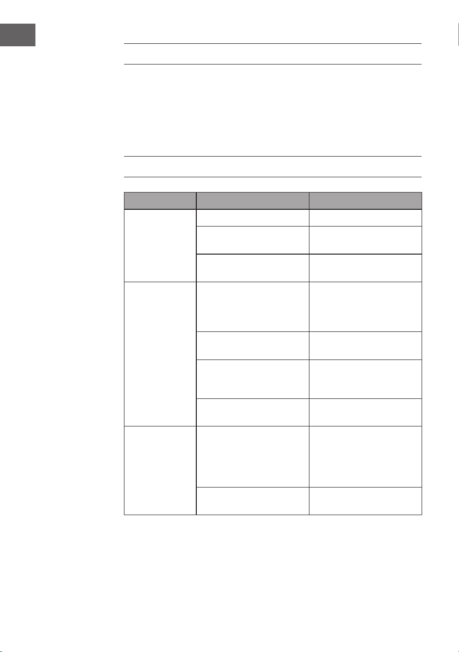
74
FR
NETTOYAGE ET ENTRETIEN
• Débranchez toujours l'appareil de l'alimentation électrique avant de le
nettoyer ou d'effectuer des travaux d'entretien.
• N'utilisez jamais une éponge mouillée pour nettoyer l'appareil.
• An de ne pas endommager le produit, il est conseillé d'utiliser un
équipement adapté aux surfaces et produits sensibles pour ralentir l'usure de
l'appareil.
DÉPANNAGE
Problème Cause possible Approche
Le ventilateur ne
tourne pas.
Fusible ou disjoncteur grillé. Vériez vos fusibles.
Câbles desserrés. Vérier que les connexions
ne sont pas desserrées.
La vitesse n'a pas été réglée
correctement.
Sélectionner une vitesse.
Le ventilateur fait
du bruit.
Le cache supérieur touche le
plafond.
Veillez à ce qu'il y ait une
distance minimale de 3 mm
entre le cache supérieur et
le plafond.
Les vis des pales du rotor
sont desserrées.
Serrer les vis.
Le ventilateur de plafond
n'est pas correctement xé
au plafond.
Serrer toutes les vis de la
platine de suspension.
La vitesse n'est pas réglée
correctement.
Sélectionner une vitesse.
Le ventilateur
oscille.
Les pales du rotor ne sont
pas réglées horizontalement
par rapport au plafond.
Déplacez le ventilateur de
manière à ce que toutes
les pales soient à la même
hauteur par rapport au
plafond.
Les vis des pales du rotor
sont desserrées.
Serrer les vis.
75
FR
CONSEILS POUR LE RECYCLAGE
S‘il existe une réglementation pour l‘élimination ou le
recyclage des appareils électriques et électroniques dans
votre pays, ce symbole sur le produit ou sur l‘emballage
indique que cet appareil ne doit pas être jeté avec les
ordures ménagères. Vous devez le déposer dans un point
de collecte pour le recyclage des équipements électriques
et électroniques. La mise au rebut conforme aux règles
protège l‘environnement et la santé de vos semblables
des conséquences négatives. Pour plus d‘informations
sur le recyclage et l‘élimination de ce produit, veuillez
contacter votre autorité locale ou votre service de
recyclage des déchets ménagers.
Ce produit contient des piles. S‘il existe une
réglementation pour l‘élimination ou le recyclage des
piles dans votre pays, vous ne devez pas les jeter avec les
ordures ménagères. Renseignez-vous sur les dispositions
locales relatives à la collecte des piles usagées. La mise au
rebut conforme aux règles protège l‘environnement et la
santé de vos semblables des conséquences négatives.
DÉCLARATION DE CONFORMITÉ
Fabricant :
Chal-Tec GmbH, Mühlenstraße 25, 10243 Berlin,
Allemagne.
Contact: [email protected]
Le soussigné, Chal-Tec GmbH, déclare que l’équipement
radioélectrique du type Sky Breeze Smart est conforme à la
directive 2014/53/UE. Le texte complet de la déclaration UE
de conformité est disponible à l’adresse internet suivante :
use.berlin/10047037
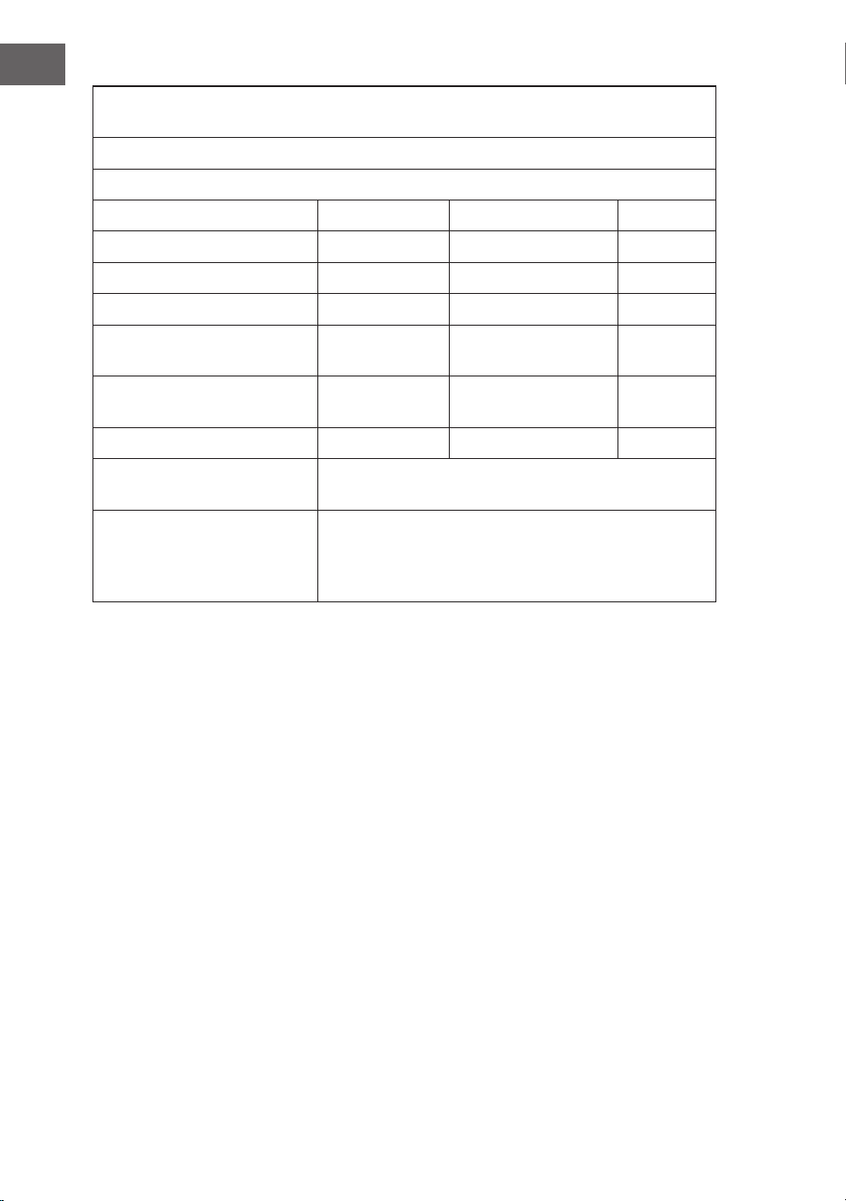
76
FR
Exigences en matière d’information sur les produits selon de RÈGLEMENT (UE) No
206/2012
Informations d’identication du ou des modèles:
10047037, 10047038, 10048079, 10048080 Klarstein SkyBreeze Smart
Description Symbole Valeur Unité
Débit d’air maximal F 169,6 m3/min
Puissance absorbée P 26,8 W
Valeur de service SV 3,3 (m3/min)/W
Consommation d’électricité en
mode «veille»
PSB 0,45 W
Niveau de puissance
acoustique
LWA <45 dB dB(A)
Vitesse maximale de l’air c 2,5 m/s
Norme de mesure de la valeur
de service
IEC 60879:2019
Coordonnées de contact
pour tout complément
d’information
Chal-Tec GmbH
Mühlenstraße 25
10243 Berlin
Allemagne
77
IT
Gentile cliente,
Ti ringraziamo per aver acquistato questo dispositivo. Ti
invitiamo a leggere attentamente le seguenti istruzioni e
a seguirle per evitare possibili danni. Non ci assumiamo
alcuna responsabilità per danni causati dalla mancata
osservanza delle istruzioni e da un uso improprio.
Scansionare il codice QR per accedere al manuale d'uso
più recente e a maggiori informazioni sul prodotto.
INDICE
DATI TECNICI
Numero dell'articolo 10047037, 10047038, 10048079, 10048080
Alimentazione 220-240 V ~ 50 Hz
Prestazioni del ventilatore 27 W
Tipo di lampada LED 16 W dimmerabile
Temperatura di colore 3000 K, 4000 K, 6500 K
Indice di resa cromatica (CRI) ≥80 Ra
Flusso massimo 170 m
3
/min
Bande de fréquence
Puissance maximale d'émission
433 MHzz
10 dBm
Questo prodotto contiene una sorgente luminosa di classe di ecienza
energetica E.
Avvertenze di sicurezza 78
Volume di consegna 79
Panoramica 81
Installazione 82
Montaggio 84
Controllo del dispositivo con smartphone 90
Pulizia e manutenzione 92
Risoluzione dei problemi 92
Smaltimento 93
Dichiarazione di conformità 93

78
IT
AVVERTENZE DI SICUREZZA
• Non ssare mai il ventilatore a una presa di corrente, ma al sotto stesso.
• La distanza minima tra le pale del ventilatore e il pavimento deve essere
superiore a 2,3 metri. La portata minima del gancio a cui è appeso il
ventilatore deve essere di 100 kg.
• Assicurarsi di installare nel cablaggio di alimentazione del ventilatore a sotto
un sezionatore onnipolare con una separazione dei contatti di almeno 3 mm
tra i poli.
• Tutti i cablaggi devono essere conformi alle norme elettriche nazionali e
locali. Se non si ha dimestichezza con il cablaggio, rivolgersi a un elettricista
qualicato.
• Per evitare possibili scosse elettriche, prima di installare il ventilatore,
scollegare l'alimentazione spegnendo gli interruttori della scatola dei fusibili
e l'interruttore a parete associato. Se non è possibile spegnere tutti gli
interruttori, ssare saldamente un avvertimento ben visibile, come un cartello,
al pannello di controllo.
• Il modello o la tipologia di riferimento delle lampade che possono essere
installate nei ventilatori costruiti per questo scopo.
• Spegnere l'alimentazione prima di effettuare il collegamento.
• Il cablaggio elettrico deve essere conforme alla normativa locale.
• Il ventilatore deve essere adeguatamente messo a terra per evitare il rischio di
scosse elettriche.
• Non montare mai il ventilatore in un ambiente umido o bagnato.
• Prestare attenzione quando si lavora vicino alle pale rotanti.
• Per ridurre il rischio di lesioni personali, ssare il ventilatore direttamente alla
struttura portante dell'edicio secondo queste istruzioni e utilizzare solo gli
accessori forniti.
• Questo dispositivo può essere utilizzato solo da bambini di età pari o
superiore a 8 anni e da persone con capacità siche, sensoriali e mentali
limitate e/o prive di esperienza e conoscenza, a condizione che siano stati
istruiti all'uso del dispositivo da una persona responsabile che comprenda i
rischi associati.
• Per ridurre il rischio di incendio, scosse elettriche o danni al motore, non
utilizzare un regolatore di velocità a stato solido con questo ventilatore.
Utilizzare esclusivamente regolatori a velocità variabile.
• I bambini devono essere sorvegliati e non devono giocare con l’apparecchio.
• Assicurarsi che il ventilatore sia spento dalla rete di alimentazione prima di
rimuovere la protezione.
• Prendere le precauzioni necessarie per evitare il riusso di gas nel locale
dalla canna fumaria aperta di apparecchi a gas o di altri combustibili (per i
ventilatori a condotto e divisori).
Nota: il ventilatore deve essere installato da una persona esperta di cablaggio
elettrico.

79
IT
VOLUME DI CONSEGNA
Copertura
Copertura impermeabile Asta e sfera di sospensione Asta
Staffa di sospensione Coperture decorative Motore
Pala Pannello della lampada Paralume
3
2
1
4
5
6
1H
2H
4H
8H
Sorgente luminosa a LED Telecomando Pacchetto a spirale

80
IT
Telecomando
3
2
1
4
5
6
1H
2H
4H
8H
Temperatura della
luce fredda-calda
on/off
Ventilazione naturale
Luce on/off
Velocità di
ventilazione
Direzione di rotazione
Timer
1 ora
2 ore
4 ore
8 ore
Intensità della luce

81
IT
PANORAMICA
1
Mounting Brsacket
2
Remonte Control Receiver
11
LED
7
3
4
5
6
8
10
12
9
Fan Blade
R Pin
Pin
Downrod
Decorative cover
Canopy
Fan Boby
Metal Base
Lamp Shade
Staffa di montaggio
Copertura
Perno R
Asta
Copertura decorativa
Struttura del ventilatore
Base in metallo
Perno
Paralume
LED
Pala del ventilatore
Ricevitore del telecomando

82
IT
INSTALLAZIONE
Preparazione all'installazione
Per evitare lesioni e danni alle persone, assicurarsi che la posizione di ssaggio
consenta alle pale di trovarsi a 2,3 m dal pavimento e a 76 cm da qualsiasi parete
o ostacolo. Assicurarsi che la scatola di giunzione sia ssata saldamente alla
struttura dell'edicio e possa sostenere l'intero peso del ventilatore.
L'installazione richiede questi attrezzi
Cacciavite, cacciavite a testa piatta, pinze o chiavi regolabili, scaletta, tronchesi e
nastro isolante.
76 cm dalla
parete o
dall'ostacolo più
vicino
2,3 m dalle pale al
pavimento

83
IT
Preparazione del luogo di posizionamento per il ventilatore
Questo ventilatore può essere montato su un sotto normale o a volta utilizzando
un'asta. La distanza dal sotto può essere aumentata utilizzando un'asta più
lunga.
20°
Installazione della staffa di sospensione
Stile di
montaggio
standard
Sostegno
Sostegno
Stile di
montaggio
inclinato
Il montaggio standard prevede la sospensione
dal sotto tramite un'asta
Montaggio inclinato consigliato per sotti a
volta o inclinati
Sotto in legno
Sotto in calcestruzzo
Praticare un foro di Ø 8 mm nel sotto in
calcestruzzo e inserire il bullone. Allineare la staffa al
foro e serrare il dado.
Copertura impermeabile
Copertura impermeabile

84
IT
MONTAGGIO
Montaggio e ssaggio del ventilatore
• Se si desidera estendere la lunghezza di sospensione del ventilatore, è
necessario rimuovere la sfera di sospensione dall'asta da 6" in dotazione per
utilizzarla con un'asta più lunga (in dotazione) (se si desidera utilizzare l'asta
da 6", seguire le istruzioni riportate di seguito).
• Per rimuovere la sfera di sospensione, allentare la vite di fermo sulla sfera e
rimuovere il perno e la clip. Abbassare la sfera di sospensione e rimuovere
il perno di arresto. Far scorrere la sfera di sospensione dall'asta originale A
sull'asta più lunga B (notare che la parte superiore dell'asta presenta un foro
per la vite di fermo; utilizzare questo foro per regolare la vite di fermo).
• Inserire il perno di arresto nella parte superiore dell'asta più lunga e sollevare
la sfera di sospensione.
• Assicurarsi che il perno di arresto sia allineato con le fessure all'interno della
sfera di sospensione e serrare saldamente la vite di fermo.
Nota: per prepararsi a far passare i li elettrici nell'asta, applicare un piccolo
pezzo di nastro isolante alle estremità dei li elettrici, in modo da tenerli uniti
quando vengono inlati nell'asta.
• Allentare le viti di fermo e il dado nella parte superiore dell'alloggiamento
del motore. Rimuovere il perno e la clip dall'asta (se non lo si è già fatto). Far
scorrere l'asta attraverso la copertura.
• Inlare i cavi elettrici nell'asta e rimuovere l'eventuale lo in eccesso dalla
parte superiore.
• Inserire l'asta nell'alloggiamento del motore e reinserire il perno e la clip
precedentemente rimossi. Serrare saldamente le viti di fermo e il dado.
• Abbassare la copertura sull'alloggiamento del motore.
Cablaggio
elettrico
Fessura per la sfera
di sospensione
Clip R
Adattatore
Copertura
Coperture decorative
Attraverso la clip
Vite di ssaggio

85
IT
Connessione del telecomando
green/yellow stripe
Light L
(blue)
Neutral N(White)
Ground
wire
N
L
L
Remote
control
receiver
input N
(Black)
(white)
Grey DC motor L
Pink DC motor L
Red DC motor L
Receiver place:
DC:
Striscia verde/gialla
Motore CC grigio L
Motore CC rosa L
Motore CC rosso L
Posizione del ricevitore
Ingresso N
(blu)
L
(nero)
Cavo di
Luce L blu
Neutro N (bianco)
messa a
terra
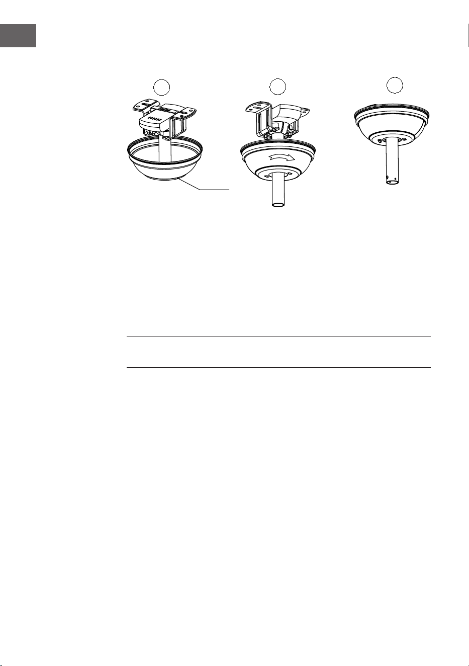
86
IT
Montaggio della copertura
2
3
1
Sollevi il tettuccio no alla staffa di aggancio, allineando le viti allentate della
staffa di aggancio con i fori scanalati del tettuccio. Giri il tettuccio per bloccarlo.
Reinserisca le viti e ssi tutte le viti con un cacciavite.
Con la staffa di sospensione ssata alla scatola di uscita e in grado di sostenere
il ventilatore, è ora pronto ad appendere il suo ventilatore. Afferri saldamente
il ventilatore con entrambe le mani. Faccia scorrere l’asta di discesa attraverso
l’apertura nella staffa di appendimento e lasci che la sfera di appendimento si
appoggi sulla staffa di appendimento. Giri la scanalatura della palla della gruccia
no a quando non si allinea con la linguetta sulla staffa della gruccia.
Nota: Si faccia aiutare da un’altra persona per tenere la scaletta in posizione
e sollevare il ventilatore no a lei, una volta salito sulla scala.
Copertura
ok

87
IT
Montaggio della lama
1
2
Risparmio di tempo: Le rondelle per le viti delle lame possono essere montate su
ogni vite della lama prima di montare le lame.
Allinei i fori delle lame con i fori delle viti del motore e stringa tutte le viti quando
tutte le lame sono montate. Ripetere l’operazione con i bracci delle lame rimanenti
prima di ssare denitivamente le viti.
Nota: Serri le viti della lama due volte.
ok
Vite
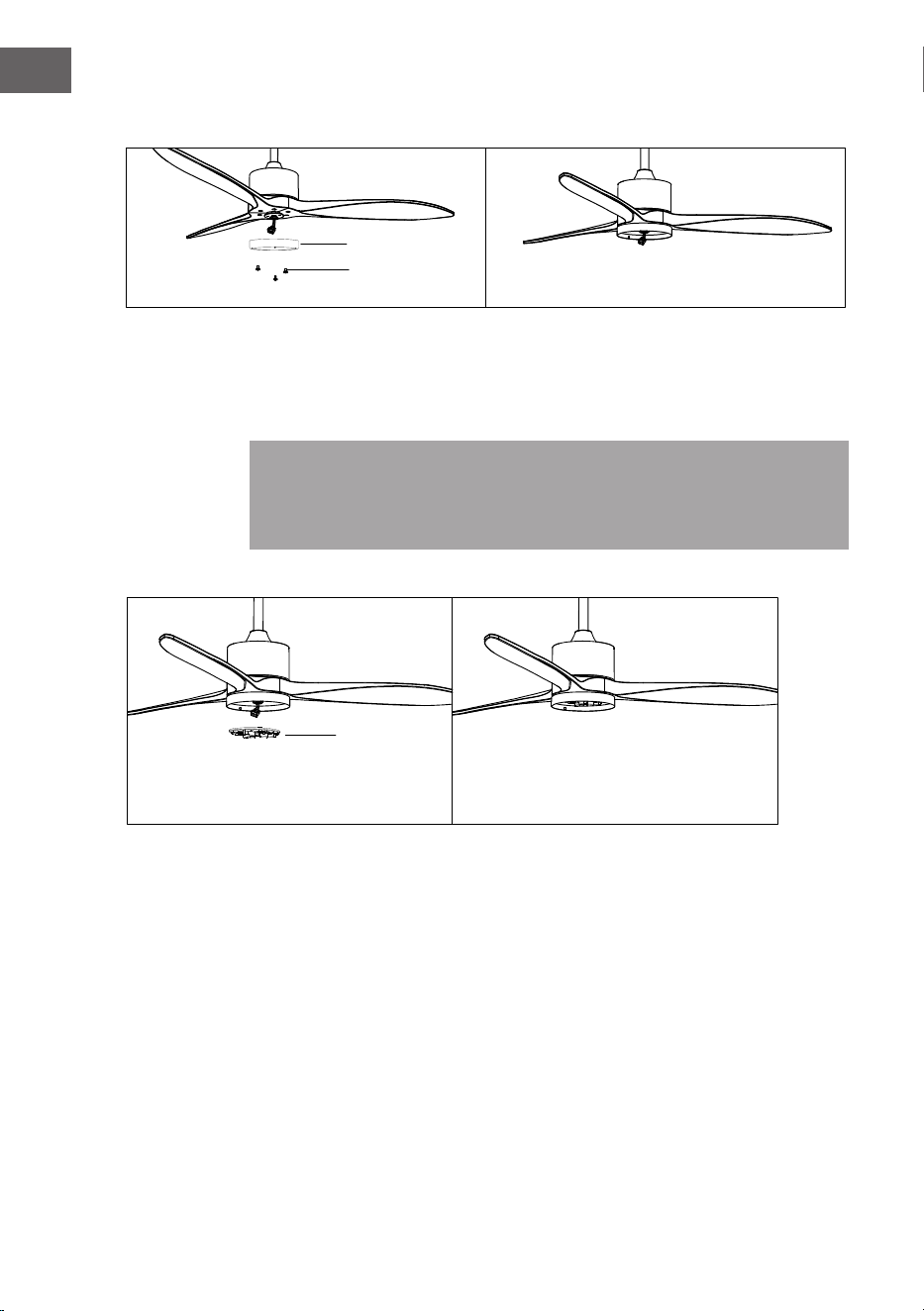
88
IT
Gruppo del pannello LED
• Svitare una vite di fermo.
• Fissare il pannello LED alla parte inferiore del ventilatore inserendo le altre
due viti di fermo nelle fessure, ruotarle in posizione, quindi ssare la vite di
fermo precedente allineando il foro della vite e il foro sulla parte inferiore del
ventilatore e stringere le due viti di fermo rimanenti per ssare il pannello LED
Nota: quando si installa o si rimuove il pannello LED, mantenere intatti i
cuscinetti isolanti. Un serraggio eccessivo o troppo rapido delle viti di fermo può
danneggiare i cuscinetti isolanti. Utilizzare l'aiuto di un'altra persona per tenere
la scaletta in posizione e sollevare il ventilatore una volta saliti sulla scala.
Montaggio del paralume
Riposizionare la copertura e il paralume sul pannello LED.
LED
ok
Pannello della lampada
Viti

89
IT
Gruppo dell'elemento decorativo
Riposizionare la copertura e il paralume sul pannello LED e ssarli con le clip
decorative e i dadi.

90
IT
DEVICE CONTROL BY SMARTPHONE
If you integrate the device into your home WiFi, you can conveniently operate it via
the associated Klarstein app. The app not only allows you to remotely control the
device via your smartphone, but also gives you access to recipes and additional
information.
Follow these steps to connect your smartphone to your Klarstein device:
1. Download the Klarstein app rst by scanning the QR code with your
smartphone (see below), or download it directly from App Store or Google
Play.
2. Make sure your smartphone is connected to the same WiFi network that your
Klarstein device is to be connected to.
3. Open the Klarstein app.
4. Sign in to your account. If you do not have an account, sign up in the Klarstein
app.
5. Follow the instructions from the app.
App Download
Use the scan function of your smartphone to scan the QR code and save the app on
your smartphone.
Note: The app provides further information on how to use the app and help on
how to connect to your device as soon as you open it for the rst time.
iOS Android

91
IT
Risoluzione dei problemi di connessione
Se il dispositivo Klarstein non viene trovato nella rete WiFi, vericare quanto segue:
1. Il dispositivo non è collegato alla presa. Assicurarsi che il dispositivo sia
collegato a una presa di corrente.
2. Il dispositivo non è in modalità di accoppiamento. Assicurarsi che la spia del
WiFi (LED) sul pannello di controllo del tuo dispositivo smart lampeggi come
indicato nelle istruzioni "Resettare le impostazioni WiFi" del tuo dispositivo
smart (sono solitamente disponibili istruzioni sulla procedura di connessione
del dispositivo).
3. Il punto di accesso WiFi non funziona a 5 GHz. Assicurarsi che il punto di
accesso operi sulla banda a 2,4 GHz e che ci sia un SSID separato sulla banda
a 2,4 GHz. Se non si è certi della frequenza operativa del punto di accesso, si
prega di contattare il provider di Internet in questione.
Importante: tenere presente che se il router WiFi è dual band, ovvero funziona
su entrambe le bande da 2,4 GHz e 5 GHz, è necessario separare gli SSID per
ciascuna banda e utilizzare l'SSID da 2,4 GHz per la connessione.
4. Impostazioni del rewall della rete WiFi; l'impostazione del rewall della rete
WiFi potrebbe non consentire all'app Klarstein di congurare le impostazioni
WiFi sul dispositivo smart. Assicurarsi di non utilizzare una rete WiFi pubblica,
ad esempio negli aeroporti, nei dormitori, nelle aziende, ecc.
5. Credenziali diverse utilizzate nello smartphone e nell'app. Assicurarsi che le
credenziali WiFi inserite nell'app Klarstein siano le stesse a cui è collegato lo
smartphone.
Seguendo i punti sopra indicati, se il dispositivo smart non riesce ancora a
connettersi all'app, contattarci via email per ricevere assistenza:

92
IT
PULIZIA E MANUTENZIONE
• Scollegare sempre il dispositivo dall'alimentazione elettrica prima di pulirlo o
di effettuare interventi di manutenzione.
• Non utilizzare mai una spugna bagnata per pulire il dispositivo.
• Per non danneggiare il prodotto, si consiglia di utilizzare attrezzature adatte
alle superci e ai prodotti sensibili, che rallenteranno l'usura del dispositivo.
RISOLUZIONE DEI PROBLEMI
Problema Possibile causa Approccio
Il ventilatore non
si avvia.
Fusibile o interruttore
automatico bruciato.
Controllare i fusibili.
Collegamenti dei cavi
allentati.
Controllare che tutti i
collegamenti non siano
allentati.
La velocità non è stata
impostata correttamente.
Selezionare una velocità.
Il ventilatore fa
rumore.
La calotta superiore tocca il
sotto.
Assicurarsi che vi sia una
distanza minima di 3 mm
tra la calotta superiore e il
sotto.
Le viti delle pale del rotore
sono allentate.
Serrare tutte le viti.
Il ventilatore non è ssato
correttamente al sotto.
Serrare tutte le viti del
pannello di sospensione.
La velocità non è regolata
correttamente.
Selezionare una velocità.
Il ventilatore
traballa.
Le pale del rotore non sono
regolate orizzontalmente
rispetto al sotto.
Spostare il ventilatore in
modo che tutte le pale siano
alla stessa altezza rispetto al
sotto.
Le viti delle pale del rotore
sono allentate.
Serrare tutte le viti.
93
IT
SMALTIMENTO
Se nel proprio paese si applicano le regolamentazioni
inerenti lo smaltimento di dispositivi elettrici ed
elettronici, questo simbolo sul prodotto o sulla confezione
segnala che questi prodotti non possono essere
smaltiti con i riuti normali e devono essere portati a
un punto di raccolta di dispositivi elettrici ed elettronici.
Grazie al corretto smaltimento dei vecchi dispositivi si
tutela il pianeta e la salute delle persone da possibili
conseguenze negative. Informazioni riguardanti il riciclo
e lo smaltimento di questi prodotti si ottengono presso
l’amministrazione locale oppure il servizio di gestione dei
riuti domestici.
Il prodotto contiene batterie. Se nel proprio paese si
applicano le regolamentazioni inerenti lo smaltimento
di batterie, non possono essere smaltite con i normali
riuti domestici. Preghiamo di informarvi sulle
regolamentazioni vigenti sullo smaltimento delle
batterie. Grazie al corretto smaltimento dei vecchi
dispositivi si tutela l’ambiente e la salute delle persone da
conseguenze negative.
DICHIARAZIONE DI CONFORMITÀ
Produttore:
Chal-Tec GmbH, Mühlenstraße 25, 10243 Berlino,
Germania.
Contattateci: [email protected]
Il fabbricante, Chal-Tec GmbH, dichiara che il tipo di
apparecchiatura radio Sky Breeze Smart è conforme alla
direttiva 2014/53/UE. Il testo completo della dichiarazione
di conformità UE è disponibile al seguente indirizzo
Internet: use.berlin/10047037
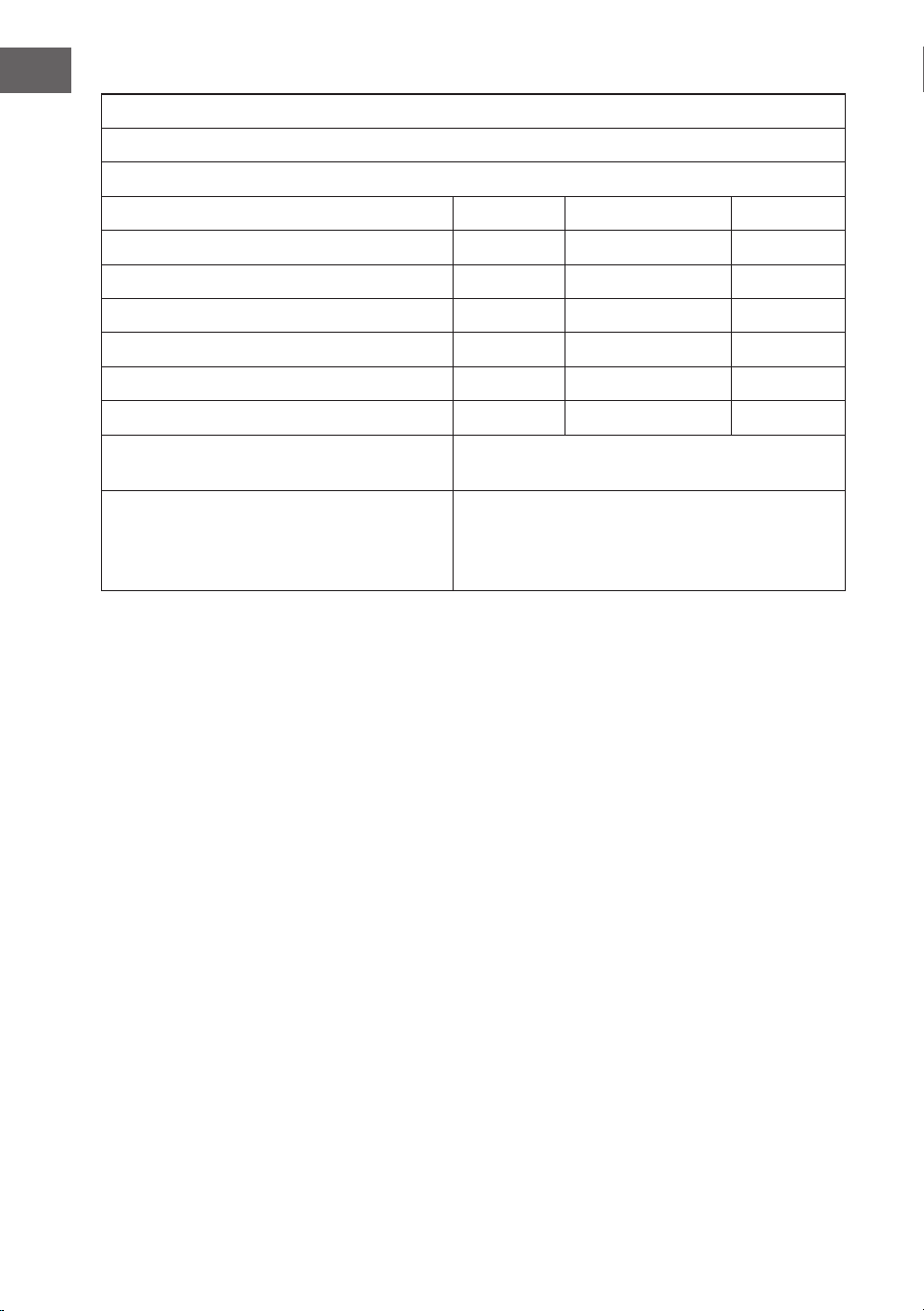
94
IT
Requisiti in materia di informazione di prodotto secondo REGOLAMENTO (UE) N. 206/2012
Informazioni per i identicare i modelli cui sono riferibili le informazioni:
10047037, 10047038, 10048079, 10048080 Klarstein SkyBreeze Smart
Descrizione Simbolo Valore Unità
Portata massima d’aria F 169,6 m3/min
Valori di esercizio P 26,8 W
Valori di esercizio SV 3,3 (m3/min)/W
Consumo elettrico in modo «attesa» PSB 0,45 W
Livello di potenza sonora del ventilatore LWA <45 dB dB(A)
Velocità massima dell’aria c 2,5 m/s
Nominativo e recapito del fabbricante o del
suo rappresentante legale
IEC 60879:2019
Referente per ulteriori informazioni Chal-Tec GmbH
Mühlenstraße 25
10243 Berlin
Deutschland