
SKU: EX_2H
User Manual
2 Head LED Exit Sign
support@sunco.com
(844) 334-9938
AMERICAN
COMPANY
Lighting made better.
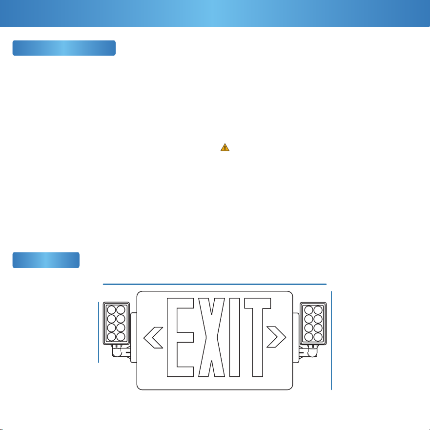
Exit Sign
1
Let there be light!
(literally)
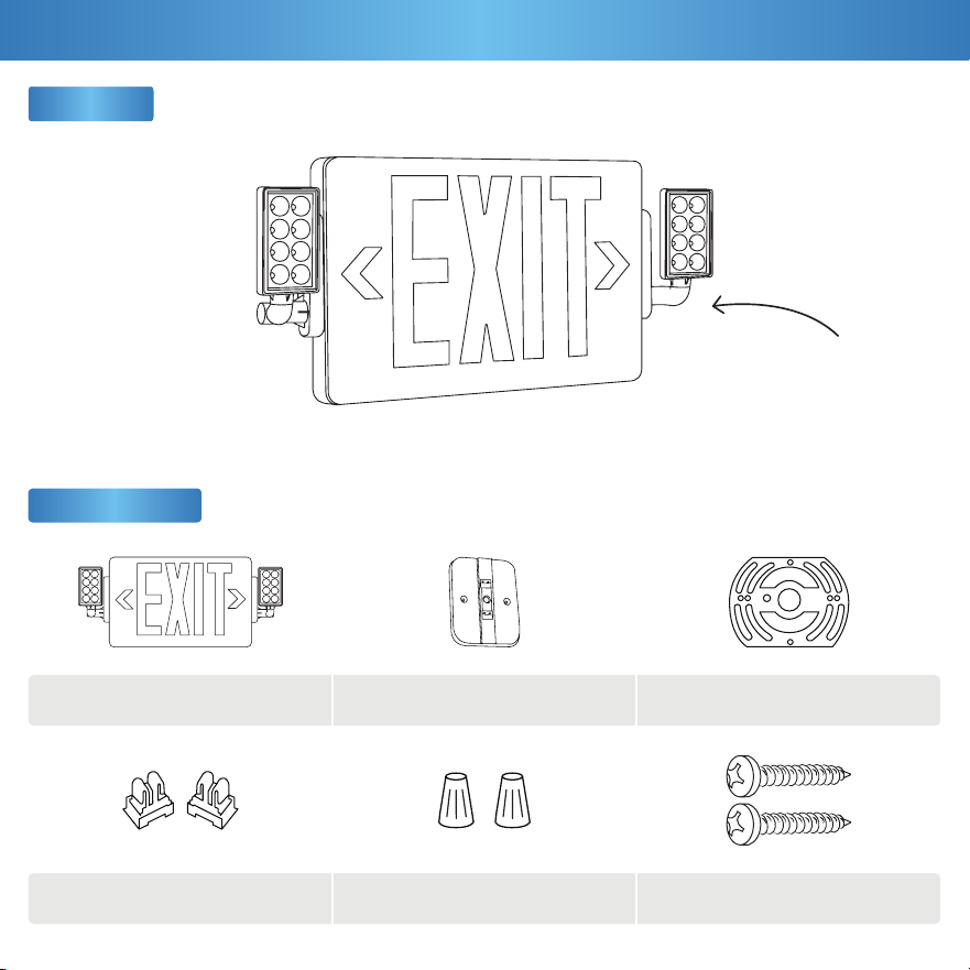
Components
x1
x2
x1
x2
Exit Sign Housing + Panel
Support Connectors
Canopy Mount
Wire Nuts
Trim Plate
Screws
x1
x2
What’s in the Box?
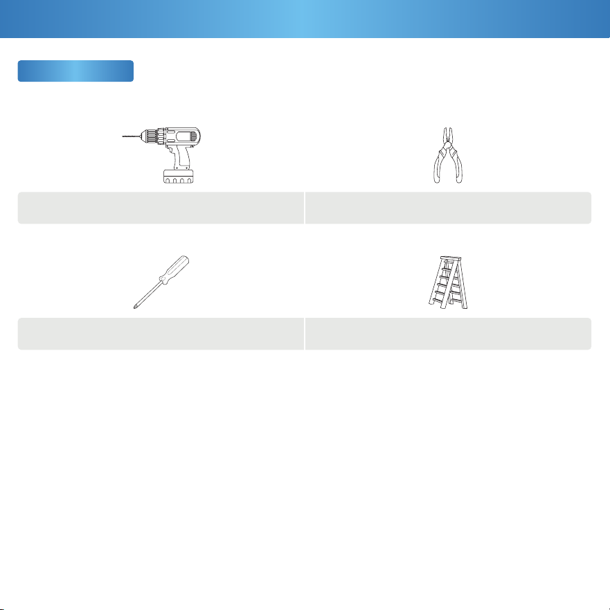
2
Ladder
Pliers
Drill
Screwdriver
Get Your Gear
IMPORTANT: Prior to exit sign installation, install junction box in ceiling or wall. When re-lamping, use only lamps
specied in the exit sign. Using other lamp types may result in transformer damage or unsafe conditions. The battery in
this unit may not be fully charged upon unboxing. After electricity is hooked up to the unit, let the battery charge for at
least 24 hours. It is then ready for normal operation. Unused wires must be capped with a wire nut.
What You Need
This device complies with Part 15 of the FCC rules.
Operation is subject to the following two conditions:
1.) This device may not cause harmful interference.
2.) This device must accept any interference that may cause
undesired operation. Please review all instructions carefully
prior to installation.
• Turn o circuit breaker before installing this xture.
• Suitable for use in damp environments at temperatures
ranging from 32°F to 104°F. Not for use where directly
exposed to water.
• Not compatible with photo controls.
• Not compatible with occupancy sensors.
• Not compatible with 3rd party sensors.
• Not compatible with dimmers.
• Not compatible with timing devices.
• All electrical connections must be in accordance with local
and National Electric Code (N.E.C.) standards.
• Please review installation manual carefully before
proceeding. Consult a qualied electrician if you are
unfamiliar with proper electrical wiring connections.
Dimensions
3
16.3”
7.6”3.6”
Safety Information
Before You Start
WARNING:
Cancer & Reproductive Harm- www.P65Warnings.ca.gov
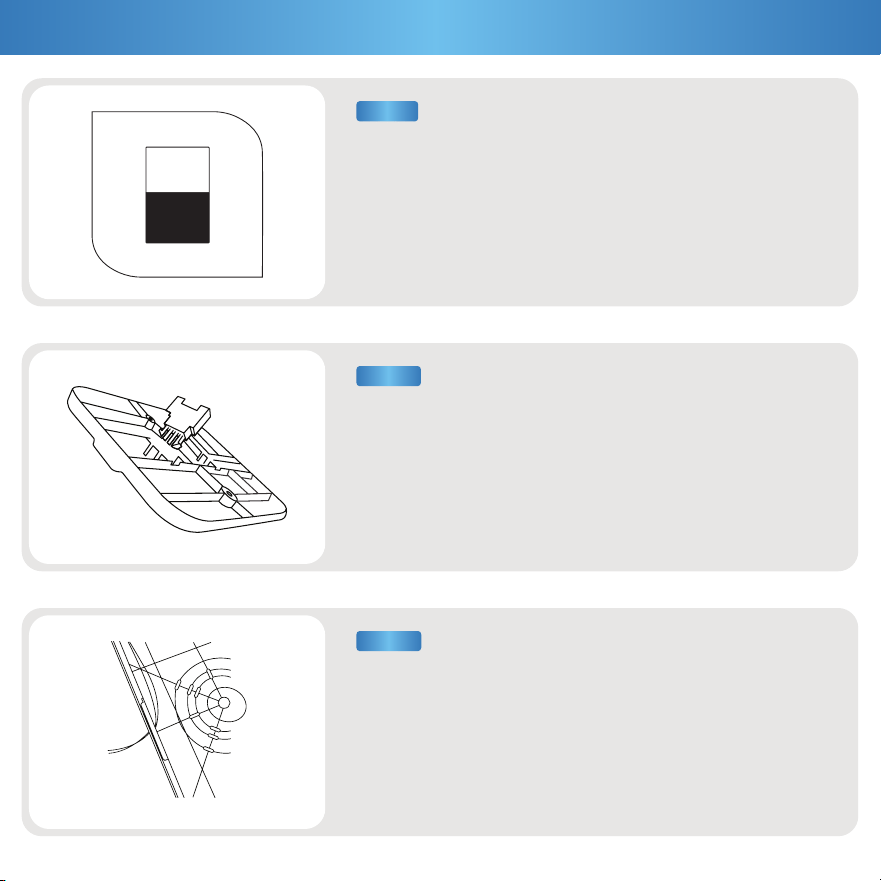
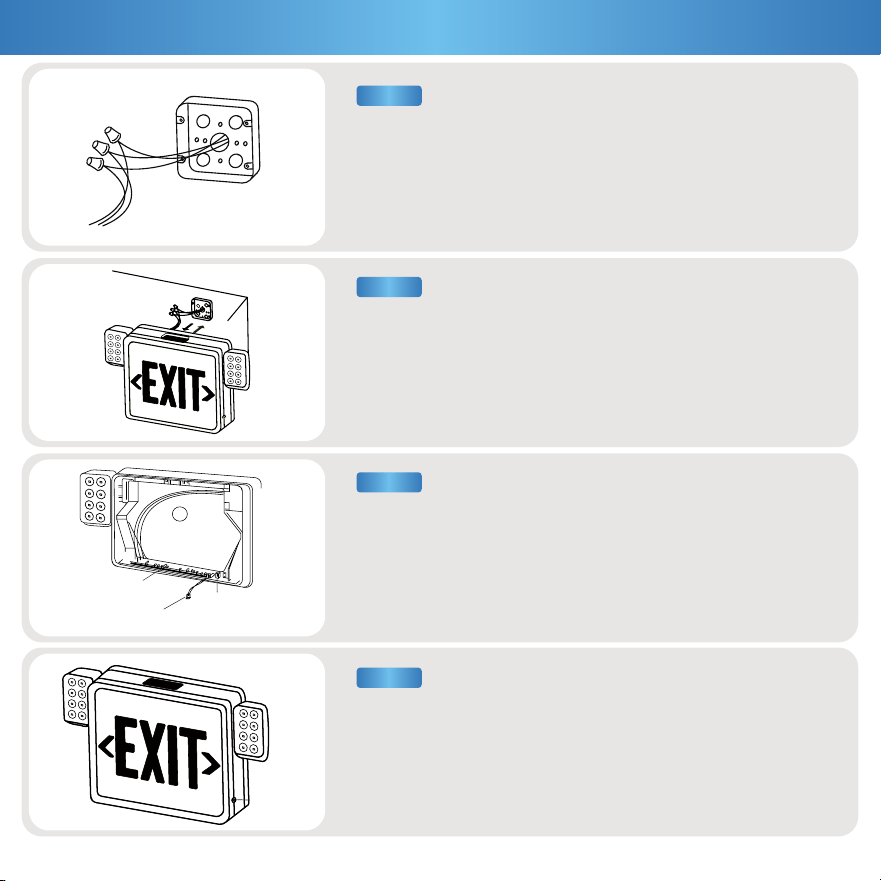
a. Unwrap canopy and mounting hardware from plastic packaging.
b. Snap two support connectors in provided slots. These will
connect canopy mount plate to top of housing.
a. Pop out top knockout. There are two slots. Feed lead wires
through hole.
b. Secure wires with wire guide.
a. Turn off circuit breaker before installation.
b. Open housing of exit sign using flathead screwdriver in slots on
top. Alternate sides to unsnap entire faceplate. Pull off faceplate &
set aside.
c. Remove mounting components (wrapped in plastic for shipping)
from the housing. Set aside.
4
ON
OFFOFF
Installation Guide(ceiling mount)
STEP 3
STEP 2
STEP 1
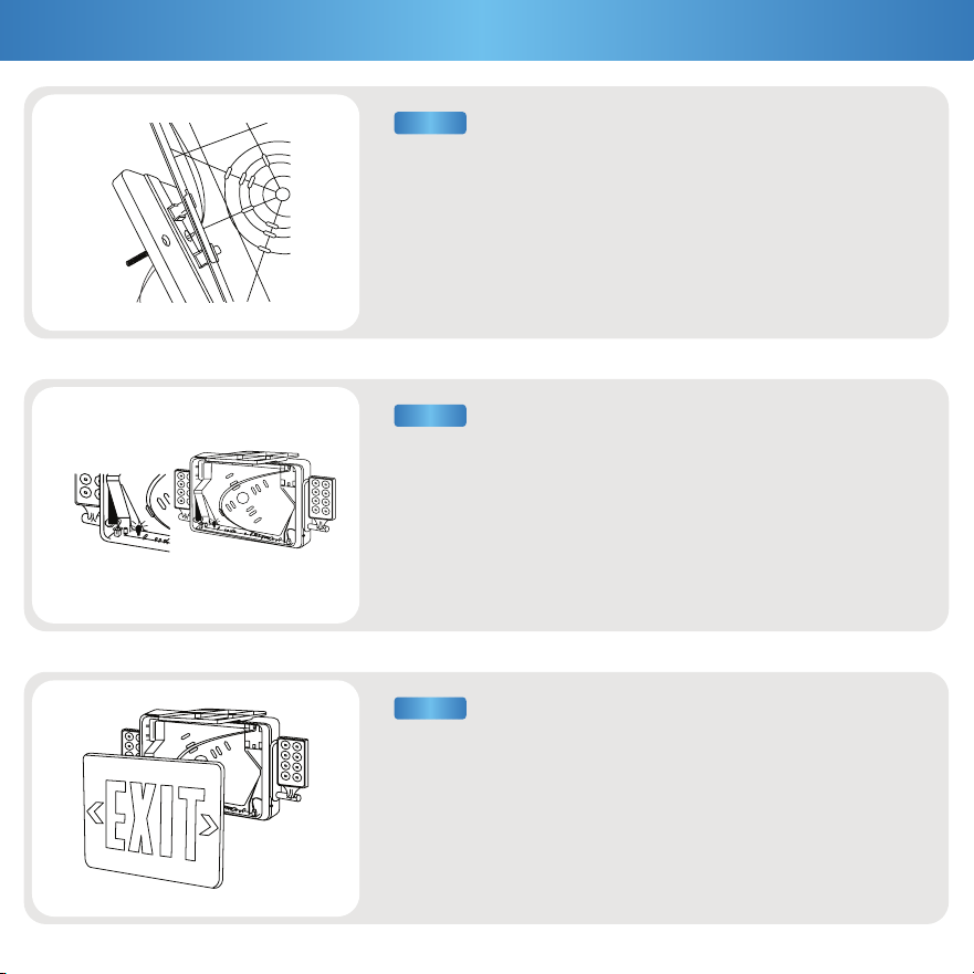
a. Align trim plate to screw holes on back of the canopy mount
plate. Turn over. Secure trim plate with 2 provided screws.
b. Feed lead wires (from face to back) through canopy mount plate &
trim plate. Snap canopy mount plate onto exit sign housing.
a. Connect exit sign lead wires to AC input leads in junction box (not
included) & cap off unused wires with wire nuts.
b. Feed excess wire into J-box. Secure canopy mount with exit sign
using included screws. Connect battery to the PC board by plugging
wire into socket.
a. Reattach faceplate. Ensure all four corners have snapped together
properly. Knock out direction arrow(s), as appropriate for your light
fixture location.
b. Turn on power. Battery may need 24 hours to charge before light
fixture is used for emergency purposes.
5
STEP 5
STEP 4
STEP 6
Installation Guide (ceiling mount)
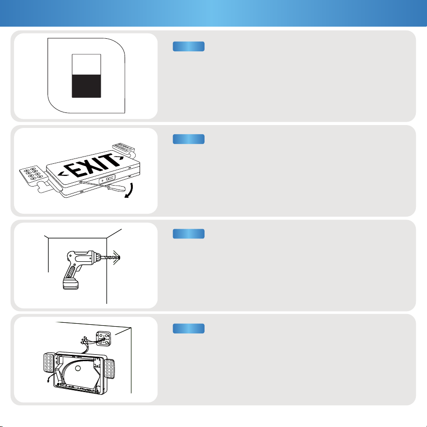
Disconnect AC power, make sure the battery is unplugged before
servicing.
(If you are replacing an existing halogen fixture, allowing the fixture
to cool away from flammable materials.)
Unsnap faceplate to open (see figure)
Drill holes for knockouts on the backplate that correspond to
junction box holes.
Feed lead wires through a hole in the center of the backplate,
ensure wires are secured into wire guides.
6
STEP 2
STEP 1
STEP 3
STEP 4
Installation Guide (wall mount)
ON
OFFOFF
Connect leads to AC input leads in the Junction Box. Black wire for
120V, Red/Orange wire for 277V.
•Cap off unused wires •Feed excess wire into a junction box
Fasten backplate to the junction box.
•Snap housing to canopy
Connect the battery (see figure)
•Snap housing on to the backplate (first top then bottom)
a.Snap-in arrows on EXIT faceplate as required
b.Secure faceplate to housing
c.Test after 24 hours of charging
STEP 6
STEP 5
STEP 7
STEP 8
Installation Guide (wall mount)
7
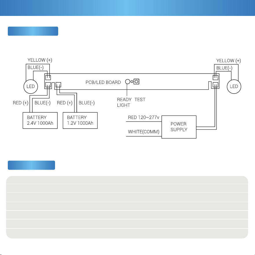
Butto
n
Battery
Battery
Connector
Socket
Voltage
Wattage
Power Factor
CRI
Weight
Housing Material
Dimmable
120V-277V
3.3W
0.48
80+
1.61 lbs
ABS+PMMA
No
120°
300LM
IP20
3.6V1000mah NI-MH
Battery
0.32A
3 Years
Beam Angle
Lumens
IP Rating
Battery
Power Source
Amps
Warranty
Wiring Diagram
6
Specifications
Product Details
7
Common Troubleshooting
Feeling in the dark about an issue with your product? No
worries! Our troubleshooting section is here to shed some light
and provide you with easy-to-follow solutions for any problem.
Light unexpectedly fails.
Light not lasting on a single charge.
Fixture buzzing with appliances or electronic devices.
Look for nearby interferences that can cause buzzing.
Such as televisions, radios, computers, etc.
Battery is not charged.
Light ickering with other lights on the same circuit.
Check that the lights on the same circuit are not
overloading the circuit.
Light ickering when turned on.
Double check if xture is properly connected
and circuit breaker hasn’t been tripped.
Verify the battery is securely plugged in and the supply
wires are properly connected.
Ensure the battery is properly connected.
Light isn’t turning on.
Test light is not working.
Fixture buzzing with power outages. Verify light is connected to surge protector securely.
Verify xture compatibility and that it is grounded.
Light is ickering when turning on.
Check that xture wiring connections are secure.
For further assistance, reach out to customer support.
Ensure the battery is properly connected and compatible.
If you still need some assistance, please feel free to
contact us with any questions. Our team of lighting experts
are happy to help brighten your day.
Battery
Flickering
Buzzing
Installation
8
This product is covered by our
industry leading 3 year warranty.
Warranty Policy
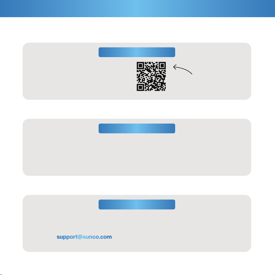
30 Day Return Policy
Sc�� �e f�� �w�
ex�r� �e�r�!
At Sunco, we value our customers and stand by
the quality and performance of our products.
If you are not completely satis ed with your
purchase, we accept returns within 30 days of
your purchase date.
Customer Support
It gets even better - scan the QR code for 2
extra years of protection!
Our Los Angeles team of lighting experts is here to assist you with all your needs! Contact us at:
Customer Service
(844) 334-9938
Call or Text:Email:

support@sunco.com
(844) 334-9938
AMERICAN
COMPANY
Lighting made better.
REV1.0