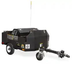
HMT-4004-0MGH Operator's Manual 1©Copyright 2019 Form #37-1467-E/S-121222
CAUTION
RISK OF INJURY!
READ MANUAL BEFORE OPERATING!
This manual is an important part of the hot water trailer and must
remain with the unit when you sell or rent it!
OPERATOR'S MANUAL
HMT-4004-0MGH
HMT-4004-0MGV
HOT WATER TRAILER
PARTS LIST

2 HMT-4004-0MGH Operator's Manual
WARNING: This product can expose you to
chemicals including Lead, which is known to
the State of California to cause cancer and birth
defects or other reproductive harm. For more
information go to www.P65Warnings.ca.gov
WARNING
WARNING: This product can expose you to
chemicals including carbon monoxide, which is
known to the State of California to cause birth
defects or other reproductive harm. For more
information go to www.P65Warnings.ca.gov
WARNING
INTRODUCTION ...........................................................................................................................................3
IMPORTANT ............................................................................................................................................3
IMPORTANT SAFETY INSTRUCTIONS ........................................................................................................4
HMT-4004-0MGH FEATURES ....................................................................................................................10
INSTALLATION & PREPARATION ...............................................................................................................11
WARNING ........ ........................................................................................................................................18
OPERATING INSTRUCTIONS ..................................................................................................................19
STORAGE & MAINTENANCE ..................................................................................................................... 23
TROUBLESHOOTING ................................................................................................................................26
MAINTENANCE CHART TRAILER..............................................................................................................28
MAINTENANCE CHART PRESSURE WASHER ......................................................................................... 29
HMT-4004-0MGH Operator's Manual 3
INTRODUCTION
Congratulations on the purchase of your new hot water trailer! You can be assured your hot water trailer was con-
structed and designed with quality and performance in mind. Each component has been rigorously tested to ensure
the highest level of acceptance.
This operator's manual was compiled for your benet. By reading and following the simple safety, installation,
operation, maintenance and troubleshooting steps described in this manual, you will receive years of trouble free
operation from your new hot water trailer. The contents of this manual are based on the latest product information
available at the time of publication. The manufacturer reserves the right to make changes in price, color, materials,
equipment, specications or models at any time without notice.
! IMPORTANT !
These paragraphs are surrounded by a "SAFETY ALERT BOX". This box is used to designate and emphasize
Safety Warnings that must be followed when operating this pressure washer.
Accompanying the Safety Warnings are "signal words" which designate the degree or level of hazard
seriousness. The "signal words" used in this manual are as follows:
DANGER: Indicates an imminently hazardous situation which, if not avoided, WILL
result in death or serious injury.
WARNING: Indicates a potentially hazardous situation which, if not avoided, COULD
result in death or serious injury.
CAUTION: Indicates a potentially hazardous situation which, if not avoided, MAY
result in minor or moderate injury.
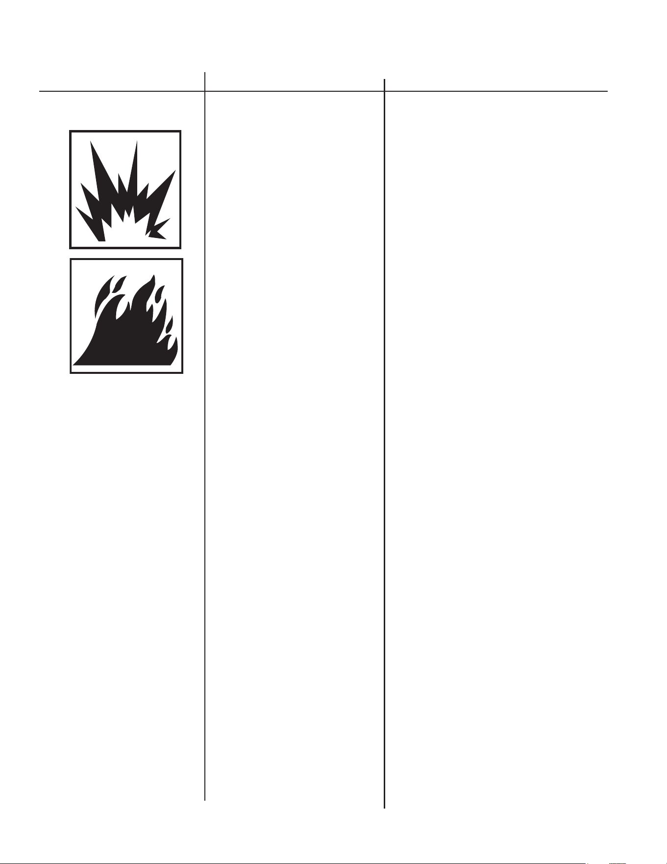
The symbols set to the left of this paragraph are "Safety Alert Symbols." These symbols are used to call attention
to items or procedures that could be dangerous to you or other persons using this equipment.
ALWAYS PROVIDE A COPY OF THIS MANUAL TO ANYONE USING THIS EQUIPMENT. READ ALL INSTRUCTIONS BEFORE
OPERATING THIS PRESSURE WASHER AND ESPECIALLY POINT OUT THE "SAFETY WARNINGS" TO PREVENT THE
POSSIBILITY OF PERSONAL INJURY TO THE OPERATOR. ONLY TRAINED OPERATORS SHOULD USE THIS PRODUCT!
Once the unit has been removed from the box, immediately write in the serial number of your unit in the space pro-
vided below.
SERIAL NUMBER_________________________________
Inspect for signs of obvious or concealed freight damage. If damage does exist, le a claim with the transportation
company immediately. Be sure that all damaged parts are replaced and the mechanical and electrical problems are
corrected prior to operation of the unit. If you require service, contact your Customer Service Representative.
Please have the following information available for all service calls:
1. Model Number
2. Serial Number
3. Date and Place of Purchase
4 HMT-4004-0MGH Operator's Manual
POTENTIAL CONSEQUENCE
PREVENTION
IMPORTANT SAFETY INSTRUCTIONS
READ ALL SAFETY WARNINGS BEFORE USING PRESSURE WASHER
RISK OF
EXPLOSION OR FIRE
Serious injury or death may occur
from normal sparks in the multiple
ignition sources or engine/burner
exhaust.
Always operate pressure washer in a well
ventilated area free of ammable vapors,
combustible dust, gases or other combus-
tible materials.
Do not store the pressure washer near an
open ame or any equipment such as a
stove, furnace, water heater, etc., which
utilizes a pilot light or sparking device.
Do not use this pressure washer to spray
ammable material!
Do not smoke while lling fuel tanks.
Never ll the fuel tanks while the engine is
running or hot. Allow the engine to cool two
minutes before refueling.
Do not refuel indoors or in a poorly venti-
lated area.
Always refuel slowly to avoid the possibility
of spilled fuel which may cause a risk of re.
Engine Fuel Tank:
If using a Gasoline Engine, refuel with gaso-
line only. Do not use diesel or fuel oil.
Burner Fuel Tank:
When refueling the Burner Fuel Tank, use
No. 1 or No. 2 fuel oil/diesel or kerosene.
Do not use gasoline, crankcase drainings, or
oil containing gasoline or solvents.
Do not operate the unit if gasoline or diesel
fuel is spilled. Wipe the pressure washer
clean and move it away from the spill.
Avoid creating any ignition until the gasoline
or diesel fuel has evaporated.
When the battery is being activated, hydro-
gen and oxygen gases in the battery are
extremely explosive. Keep open sparks and
ames away from the battery at all times,
especially when charging the battery.
Be certain to disconnect the battery ground
terminal before servicing. When discon-
necting the cable from the battery, start
with the negative terminal, and when con-
necting them, start with the positive cable.
When charging the battery, remove the bat-
tery vent plugs.
Use only a voltmeter or hydrometer to check
a battery charge.
DO NOT jump start the battery unless both
batteries are of equal voltage and amper-
age.
HAZARD
Serious injury or death may occur
from the battery.
Serious injury or death may occur
as a result of improper fueling.
HMT-4004-0MGH Operator's Manual 5
HAZARD
POTENTIAL CONSEQUENCE
PREVENTION
IMPORTANT SAFETY INSTRUCTIONS
READ ALL SAFETY WARNINGS BEFORE USING PRESSURE WASHER
Serious injury or death may occur
from inhaling engine/burner ex-
haust or dangerous vapors. The
engine exhaust from this product
contains chemicals known to the
State of California to cause can-
cer, birth defects, or other repro-
ductive harm.
A spark arrester must be added to the
mufer of this engine when using on land
covered with any ammable agricultural
crop (hay and grain), and if they are used
in or near brush or forested areas. The
arrester must be maintained in effective
working order by the operator. In the state
of California, the above is required by law.
(Section 4442 and 4443 of the California
Public Resources Code.) Other states
may have similar laws. Federal laws apply
on Federal lands.
This pressure washer has a Safety Re-
lief Valve which should never be altered,
modied, removed or made inoperative. If
the device fails, replace immediately with
genuine manufacturer replacement part.
Never operate this pressure washer in an
enclosed area. Always make certain there
is adequate ventilation (fresh outside air)
for breathing and combustion. This will
prevent the buildup of dangerous carbon
monoxide gases. Beware of poorly ven-
tilated areas, or areas with exhaust fans
which can cause poor air exchange.
Follow all safety instructions provided with
the materials you are spraying. Use of a
respirator may be required when work-
ing with some materials. Do not use this
pressure washer to dispense hazardous
detergents.
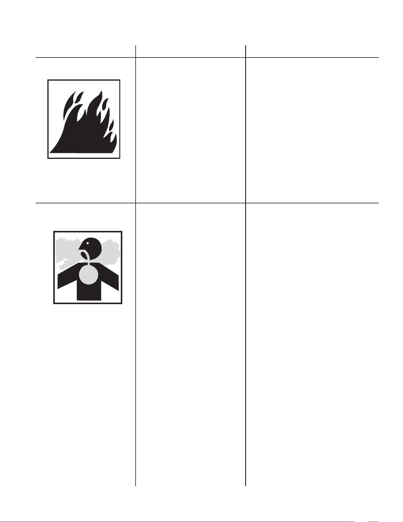
RISK OF
ASPHYXIATION
Serious injury or death may occur
from a ground re caused by a muf-
er spark.
RISK OF FIRE
Serious injury or death may occur
if system safety's are not properly
maintained.
6 HMT-4004-0MGH Operator's Manual
HAZARD POTENTIAL CONSEQUENCE PREVENTION
IMPORTANT SAFETY INSTRUCTIONS
READ ALL SAFETY WARNINGS BEFORE USING PRESSURE WASHER
Keep clear of nozzle and spray! Never
put your hand, ngers or body directly
over the spray nozzle.
Never point the high pressure discharge
spray at yourself or anyone else. This
equipment is to be used only by trained
operators.
Always keep operating area clear of all
persons.
Do not allow children to operate this unit.
Seek emergency medical care if the spray
appears to have penetrated the skin! Do
not treat as a simple cut!!
High pressure hoses and fuel lines should
be inspected daily for signs of wear. If ev-
idence of failure exists, promptly replace
all suspect hoses and fuel lines to prevent
the possibility of injury from the high pres-
sure spray. If a hose or tting is leaking,
Never place your hand directly on the leak
Never operate the gun with the trigger
wired in the open position. To prevent ac-
cidental discharge, the trigger gun should
be securely locked when not in use.
Before removing the spray nozzle or
servicing the unit, always shut off the unit
and trigger the gun to release trapped
pressure. (Even after you shut off the
unit, there is high pressure water left in
the pump, hose and gun until you release
it by triggering the gun.)
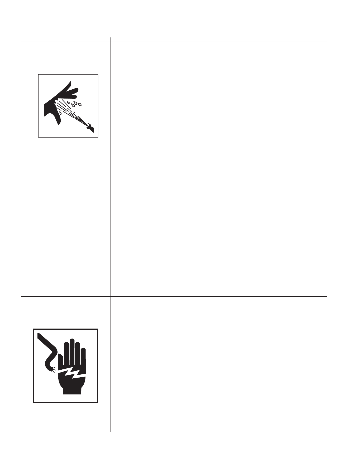
Serious injury or death could
occur from high pressure spray
penetrating the skin.
RISK OF INJECTION
OR
SEVERE CUTTING INJURY
RISK OF
ELECTROCUTION
OR ELECTRICAL SHOCK
Serious injury or death may occur
from contact with electricity.
Do not direct spray on or into electrical
installations of any kind! This includes
electrical outlets, light bulbs, fuse boxes,
transformers, the unit itself, etc.
Do not allow metal components of the
pressure washer to come in contact with
live electrical components.
HMT-4004-0MGH Operator's Manual 7
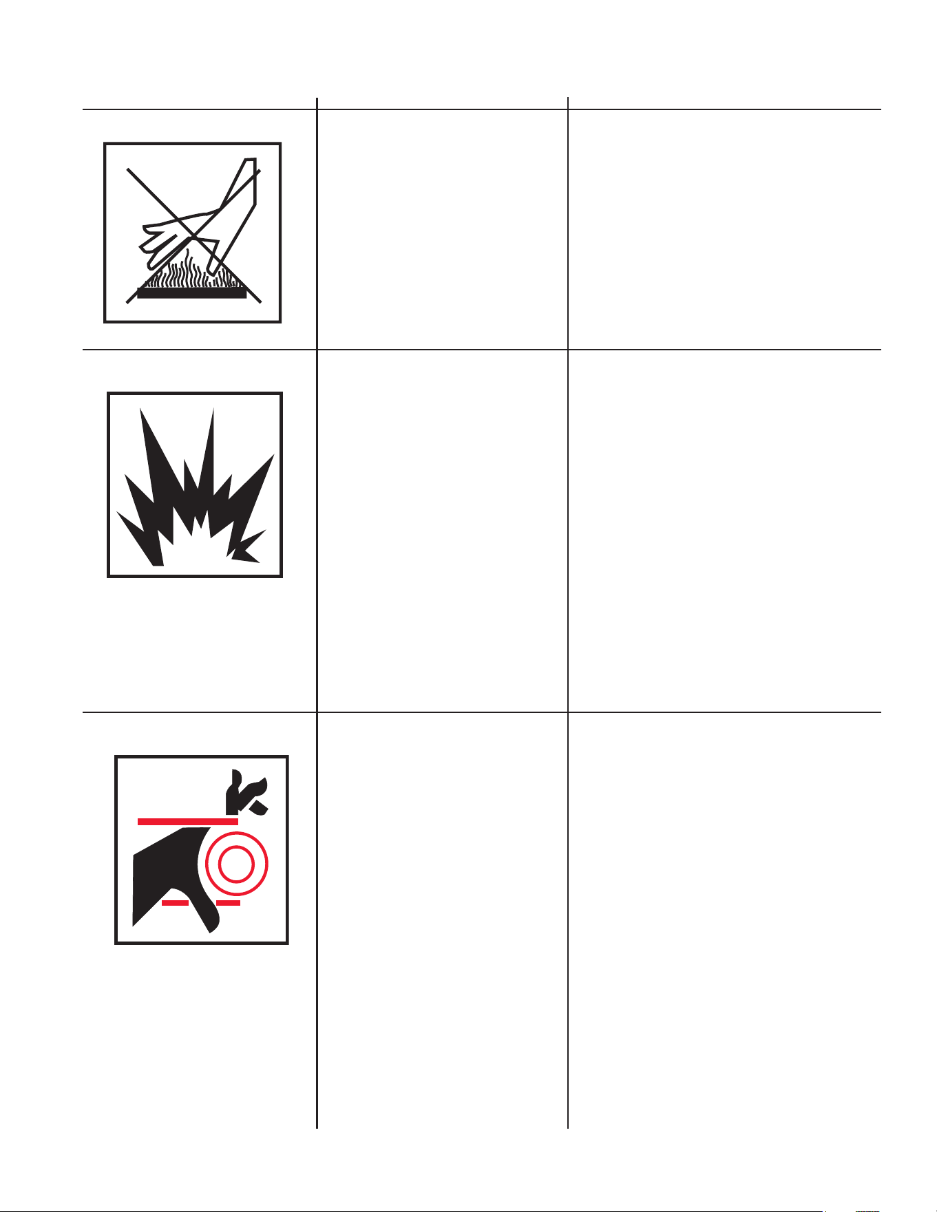
RISK OF BURNS
Serious injury may occur from
touching the engine, mufer or
heat exchanger. These areas can
remain hot for some time after
the pressure washer is shutdown.
Serious injury may occur from a
pressure washer malfunction or
exploding accessories if incorrect
system components, attachments
or accessories are used.
Never make adjustments to the factory set
pressures.
Never exceed manufacturers maximum al-
lowable pressure rating of attachments.
Do not allow any hoses to make contact
with the engine, mufer, or heat exchanger
to prevent the possibility of bursting. Avoid
dragging the hoses over abrasive surfaces
such as cement.
Use only manufacturer recommended repair
parts for your pressure washer.
In freezing temperatures, the unit must al-
ways be warm enough to ensure there is no
ice formation in the pump. Do not start the
pressure washer if it has been transported in
an open or non heated vehicle without rst
allowing the entire unit to thaw.
RISK OF BURSTING
Before making any adjustments, be cer-
tain the engine is turned off. Be certain
to disconnect the battery ground terminal
before servicing and the ignition cable(s)
is removed from the spark plug(s). Turning
the machinery over by hand during adjust-
ment or cleaning might start the engine and
machinery with it.
Do not operate the unit without all protective
covers in place.
Never allow any part of your body to contact
the engine, mufer or heat exchanger.
Serious injury may occur to the
operator from moving parts on the
pressure washer.
RISK FROM MOVING PARTS
HAZARD POTENTIAL CONSEQUENCE PREVENTION
IMPORTANT SAFETY INSTRUCTIONS
READ ALL SAFETY WARNINGS BEFORE USING PRESSURE WASHER
Serious injury or death may occur
if attempting to start the pressure
washer when the pump is frozen.
8 HMT-4004-0MGH Operator's Manual
RISK OF BODILY INJURY
IMPORTANT SAFETY INSTRUCTIONS
READ ALL SAFETY WARNINGS BEFORE USING PRESSURE WASHER
Serious injury or death may occur
from detergents contacting the
skin.
Serious injury can occur from
loose debris being propelled at a
high speed from the spray gun.
Injury may occur if the operator
loses his balance caused by the
thrust of water traveling through
the spray nozzle.
Seek emergency medical care if you are
using cleaning agents and the spray ap-
pears to have penetrated the skin! Do not
treat as a simple cut. Be prepared to tell a
physician exactly what kind of detergents
you were using by reading the Material
Safety Data Sheet (MSDS) provided with
your detergent.
Never use any solvents or highly corrosive
detergents or acid type cleaners with this
pressure washer.
Protective equipment such as rubber suits,
gloves and respirators are advisable, espe-
cially when using cleaning detergents.
Keep all detergents out of the reach of
children!
Always wear protective goggles when oper-
ating the unit to shield the eyes from ying
debris and detergents.
Do not direct spray toward fragile materials
such as glass for shattering could occur.
Stay alert-watch what you are doing. Do
not operate the unit when fatigued or under
the inuence of alcohol or drugs.
Never squeeze the trigger unless securely
braced.
Do not overreach or stand on unstable
support.
Wet surfaces can be slippery, wear protec-
tive foot gear and keep good footing and
balance at all times.
Never trigger the gun while on a ladder or
roof.
HAZARD
POTENTIAL CONSEQUENCE
PREVENTION
HMT-4004-0MGH Operator's Manual 9
RISK OF BODILY INJURY
IMPORTANT SAFETY INSTRUCTIONS
READ ALL SAFETY WARNINGS BEFORE USING PRESSURE WASHER
Always hold on rmly to the gun/lance
assembly when starting and operating the
unit. Failure to do so can cause the lance
to fall and whip dangerously.
Know how to stop the pressure washer and
bleed pressures quickly. Be thoroughly
familiar with controls.
Follow the maintence instructions specied
in the manual.
Do not leave pressurized unit unattended.
Shut off the pressure washer and release
trapped pressure before leaving.
Do not operate the unit if you see any fuel,
oil or water leaks from the machine. Do not
resume operation until the unit has been in-
spected and repaired by a qualied service
person.
Never run the unit with the governor dis-
connected or operate at excessive speeds.
Place unit in a clean, dry, at area for
servicing. Before servicing the unit: turn
the unit off, relieve the water pressure from
the trigger gun, and allow the unit to cool
down. Service in clean, dry, at area. If ap-
plicable, block wheels to prevent unit from
moving.
Do not move the unit by pulling on the
hose.
HAZARD
POTENTIAL CONSEQUENCE
PREVENTION
!SAVE THESE INSTRUCTIONS!
Injury may occur from the pressure
washer.
10 HMT-4004-0MGH Operator's Manual
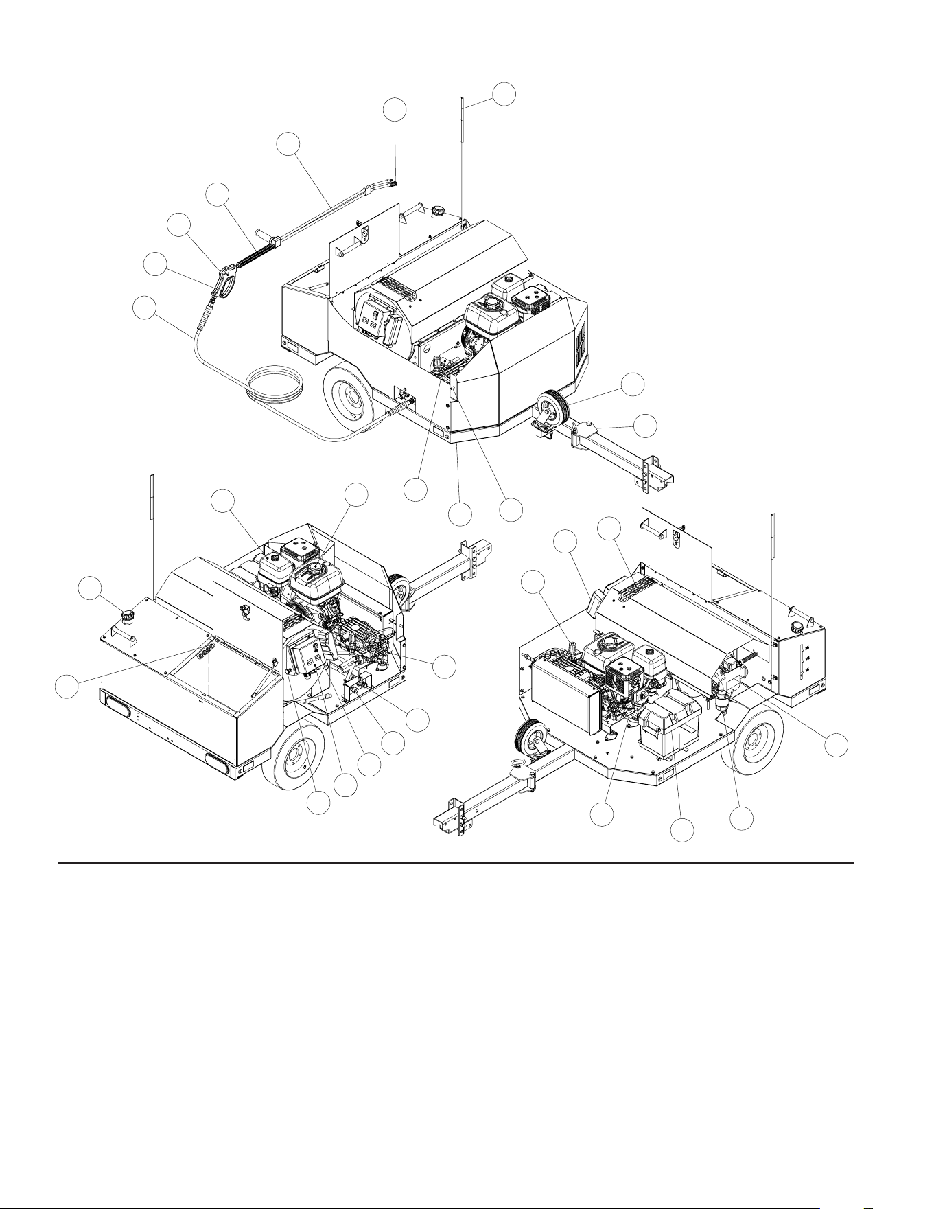
HMT-4004-0MGH FEATURES
1 Quick Connect Nozzle Holder
2 Fuel Tank
3 Engine
4 Gas Tank
5 Choke
6 Control Panel
7 Rocker Switch - Burner
8 Water Inlet
9 Water Outlet
10 High Pressure Pump
11 Gun/Wand Holder
12 Frame Assembly
13 Pressure Switch
14 High Pressure Hose
15 Trigger Safety Lock
16 Trigger Gun
17 Insulated Lance
18 Adjustable Pressure Dual Lance
19 High Pressure Nozzle
20 Safety Flag
21 Caster Assembly
22 Swing-Away Coupler
23 Unloader
24 Key Switch
25 Heat Exchanger Outlet
26 Burner
27 Fuel Filter/Water Seperator
28 Battery Box
29 Engine Oil Drain
HMT FEATURES 030920
20
16
15
17
18
19
21
22
14
12
11
13
1
6
8
9
10
2
3
7
4
5
25
23
27
26
28
29
24

HMT-4004-0MGH Operator's Manual 11
INSTALLATION & PREPARATION
SAFETY:
WARNING: DO NOT OPERATE TRAILER UNTIL THIS MANUAL HAS BEEN READ AND UNDERSTOOD.
1. Thoroughly read and understand all instructions before operating this trailer.
REPORTING SAFETY DEFECTS:
If you believe that your vehicle has a defect which could cause a crash or could cause injury or death, you should
immediately inform the National Highway Trafc Safety Administration (NHTSA) in addition to notifying the trailer
manufacturer.
If NHTSA receives similar complaints, it may open an investigation, and if it nds that a safety defect exists in a
group of vehicles, it may order a recall and remedy campaign. However, NHTSA cannot become involved in individu-
al problems between you, and your local dealer.
To contact NHTSA, you may either call the Auto Safety Hotline toll free at 1-800-424-9393 (or 366-0123 in Washing-
ton, DC area) or write to NHTSA, U.S. Department of Transportation, Washington, DC 20590. You can also obtain
information about motor vehicle safety from the Hotline.
BEFORE TOWING TRAILER:
WARNING: BEFORE USING A TOW VEHICLE WITH A TRAILER, VERIFY THAT THE VEHICLE IS DESIGNED
FOR THE LOAD. USING A VEHICLE THAT IS TOO SMALL IS VERY DANGEROUS. BE CERTAIN THAT IT
CAN HANDLE THE M.G.T.W. (MAXIMUM GROSS TRAILER WEIGHT) AND THE TONGUE WEIGHT FOR
SAFE TOWING AND BRAKING.
SELECTING THE PROPER TOWING EQUIPMENT
WEIGHT
When selecting the proper towing equipment, the two most important factors that must be considered are the
M.G.T.W. (Maximum Gross Trailer Weight) and the Tongue Weight. The M.G.T.W. is the total weight of the trailer plus
the payload in the trailer. The tongue weight is the downward pressure exerted at the coupler. The easiest way to
measure the gross trailer weight is to place the loaded trailer on a vehicle scale making sure that the scales are sup-
porting the entire weight of the loaded trailer.
The easiest method to measure tongue weight (up to 300 lbs.) is to place the jack stand (trailer tongue) on a bath-
room scale making sure the trailer is level. For heavier tongue weights, place a board across the bathroom scale and
a solid object of the same thickness as the scales with a piece of pipe between each. The trailer tongue should be
level and in its normal towing position. Multiply the scale reading by three (3) to obtain the tongue weight. Make sure
the tow vehicle is able to tow the load.
• Be sure hitch capacity is equal to or greater than the load when mounted on the vehicle.
• Be sure the size and rating of the hitch ball is equal to or greater than the load.
• Make sure the safety chain(s) rating is equal to or greater than twice the maximum gross trailer weight
rating of your trailer.
• It is against the law to carry passengers in the back of any trailer.
• Any alterations or changes made to the trailer void any express or implied warranties on the trailer or
towing equipment.
• Check lug nuts for tightness before initial trip, at 25 miles, every 100 miles of operation thereafter.
TOW VEHICLE
Make sure the vehicle you are using to tow the trailer is capable of towing the weight. Check the vehicle Owner's
Manual for towing capability of the towing vehicle or contact the car dealer for this information. Make sure the tow
vehicle is able to tow the load. Vehicle brake capacity is extremely critical and the tow vehicle must be able to handle
the additional weight of the trailer. Radiator and transmission cooling must also be considered.
TOW HITCH CAPACITY
Hitch Class Maximum Tow Capacity Maximum Tongue Weight
Sub Class I 1000 Lbs. 100 Lbs.
Class I 2000 Lbs. 200 Lbs.
Class II 3500 Lbs. 300 Lbs.
Class III and 4 5000 Lbs. Plus 500 Lbs. Plus

12 HMT-4004-0MGH Operator's Manual
SAFETY CHAINS
Listed in the chart below are the different class's of safety chains and the rated load each chain must be capable of
withstanding.
WARNING: FAILURE TO PROPERLY ATTACH SAFETY CHAINS BETWEEN THE TRAILER AND TOW
VEHICLE CAN RESULT IN A RUNAWAY TRAILER.
WARNING: TO AVOID ACCIDENTS, BEFORE TRAILERING:
• Hitch only to ball size marked on coupling.
• Ball clamp must capture ball and lever or hand wheel is fully clamped
• Cross safety chains under coupling.
• Allow only enough slack for turns.
ELECTRICAL TRAILER WIRING
All trailers must have taillights, brake lights and turn signals connected to the towing vehicle's electrical system. It
is also recommended that a heavy duty turn signal asher and emergency asher (if separate) be installed since the
trailer lights place an extra load on car asher units.
TOWING HEAVY TRAILER LOADS
Additional equipment. The following items may be helpful for towing heavy loads. Consult your vehicle's owner
manual or dealership for recommended towing accessories.
• Overload Springs
• Overload or air shocks
• Transmission Oil Cooler
• Engine Oil Cooler
• Coolant Recovery System
• Heavy Duty Fan
• Side View Mirrors
• Sway Control
TIRE PRESSURE
Proper air pressure for your tires is printed on the sidewall. Check pressure while tires are cold. Do not raise or lower
pressure to meet load. Pressure other than recommended pressure will lead to excessive tire wear or tire failure.
Balancing recommended. Preferred balancing method is to center off of stud holes, since 13" through 16.5 wheels
are not hub piloted.
WARNING: FOR A NEW TRAILER, THE WHEEL LUG NUTS SHOULD BE TIGHTENED TO THE PROPER
TORQUE SPECIFICATION BEFORE USE, AFTER 25 MILES OF OPERATION AND EVERY 100 MILES
OF OPERATION THEREAFTER. FAILURE TO CHECK THE LUG NUTS FOR PROPER TIGHTNESS CAN
RESULT IN AN ACCIDENT DUE TO A WHEEL FALLING FROM THE TRAILER.
WARNING: NEVER OPERATE A TRAILER OR TOW VEHICLE THAT HAS A LOOSE, MISSING OR BROKEN
LUG NUT. THE TRAILER IS DESIGNED FOR SAFE OPERATION WITH ALL LUG NUTS INSTALLED AND
ALL AT THE PROPER TORQUE RATING. OPERATING THE TRAILER WITH ONE OR MORE BROKEN
OR MISSING LUG NUTS GREATLY INCREASES THE LOAD ON THE REMAINING NUTS AND CAN
CAUSE FAILURE OF THE REMAINING NUTS THAT CAN RESULT IN AN ACCIDENT DUE TO A WHEEL
FALLING FROM THE TRAILER.
INSTALLATION & PREPARATION
Trailer Class Trailer weigth GVWR in lbs. Minimum braking strength in lbs.
Class I to 2000 lbs. 2000 lbs.
Class II 2000 to 3500 lbs. 3500 lbs.
Class III 3500 to 5000 lbs. 5000 lbs.
HMT-4004-0MGH Operator's Manual 13
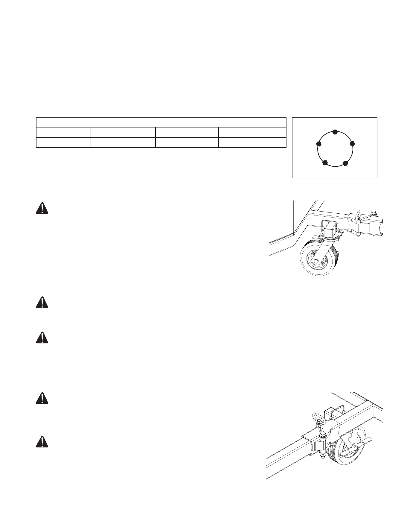
WHEEL LUGS
Wheel lug nuts must be tightened with a torque wrench. Refer to the chart below for proper torque.
1. Start all bolts or nuts by hand to prevent cross threading.
2. Tighten bolts or nuts following sequence at right.
3. Tightening of the fasteners should be done in stages. Following the recommened sequence, tighten fasteners per
wheel torque chart below.
4. Wheel nuts/bolts shuld be torqued before rst road use and after each wheel removal. Check and re-torque after
rst 10 miles, 25 miles and again at 50 miles.. Check periodically thereafter.
CASTER OPERATION
This trailer is equipped with a tongue mounted caster for use when not coupled to the tow vehicle.
WARNING: THE CASTER MUST BE IN THE UP POSITION WHEN
ATTACHED TO THE TOW VEHICLE FOR SAFE AND PROPER
TOWING.
To place the caster in the up position remove the locking safety pin and
remove caster from trailer. Rotate caster bracket 90 degrees and install on
trailer. Install the safety pin and ensure lock wire is secure.
BRAKE OPERATION
This trailer is equipped with a caster mounted brake mechanism for use when
not coupled to the tow vehicle.
WARNING: TO AVOID INJURY, THE TRAILER BRAKE MUST BE APPLIED WHEN OPERATING THE UNIT
AND WHEN NOT IN USE.
To engage the caster brake simply push down on the brake lever using your foot. To release the caster brake pull up
on the brake lever until it is in the horizontal position.
ATTENTION: PLACING BRAKE LEVER ABOVE HORIZONTAL POSITION WILL NOT ALLOW THE CASTER
TO SWIVEL AND CAN CAUSE PAINT DAMAGE.
SWING-AWAY TONGUE OPERATION
This trailer is equipped with a swing-away tongue coupler kit for compact storage.
WARNING: HINGE PIN MUST BE INSTALLED AND SECURED IN
SWING-AWAY WHEN ATTACHED TO THE TOW VEHICLE FOR
SAFE AND PROPER TOWING.
To operate swing-away coupler remove cotter pin from hinge pin. Remove
hinge pin from coupler and swing tongue to side.
ATTENTION: INSTALL HINGE PIN IN STATIONARY SIDE OF SWING-
AWAY WHEN IN USE TO PREVENT LOSS OF DAMAGE.
INSTALLATION & PREPARATION
Torque Sequence
Wheel size 1st Stage 2nd Stage 3rd Stage
16" 20-25 50-60 80-90
1
2
34
5
14 HMT-4004-0MGH Operator's Manual
SET-UP:
1. This unit should only be placed on a level surface to ensure proper lubrication for the engine and water pump while
operating. Never spray water directly on the unit.
WARNING: DANGER RISK OF EXPLOSION OR FIRE! -WHEN CHARGING BATTERIES, THEY GENERATE
A HIGHLY EXPLOSIVE HYDROGEN GAS. A SPARK COULD CAUSE AN EXPLOSION OR FIRE!
-DO NOT JUMP START BATTERY UNLESS BOTH BATTERIES ARE OF EQUAL VOLTS & AMPS.
-DO NOT SMOKE OR ALLOW SPARKS OR FLAMES NEAR THE BATTERY.
-DO NOT PLACE UNIT IN AN AREA WHERE FLAMMABLE GAS VAPORS MAY BE PRESENT. A SPARK
COULD CAUSE AN EXPLOSION OR FIRE.
WARNING: RISK OF UNIT BURSTING! DO NOT STORE/OPERATE UNIT IN FREEZING ENVIRONMENTS!
WARNING: RISK OF ASPHYXIATION! USE THIS PRODUCT ONLY IN WELL VENTILATED AREAS! DO NOT
OPERATE IN AN ENCLOSED AREA. THE EXHAUST CONTAINS CARBON MONOXIDE, A POISONOUS,
ODORLESS AND INVISIBLE GAS. BREATHING THIS GAS CAN CAUSE SERIOUS INJURY, ILLNESS &
POSSIBLE DEATH.
2. Do not use unit in an area:
a. with insufcient ventilation.
b. where there is evidence of oil, gas or fuel leaks.
c. where ammable gas vapors may be present.
This unit has multiple ignition sources that could cause an explosion or re.
3. Do not allow the unit to be exposed to freezing temperatures. If any part of the unit becomes frozen, excessive
pressure may build up in the unit which could cause it to burst resulting in possible serious injury to the operator
or bystanders.
4. Pump oil level should be checked before each use. Check oil level on sight glass on backside of pump. Oil should
be half way up the sight glass. If the level appears to be low, ll with 10-40W non-detergent pump oil. The oil level
can also be checked by using the dipstik on the top of the pump.
5. Battery Specications:
- RV / Marine Dual Purpose Deep Cycle / Cranking Battery.
- BCI Group 24DC
- Battery Box Size: 11" L x 7 1/2" W x 8 1/4" H (Battery can be slightly taller and still be covered by lid.)
- Battery should have lifting strap for easy installation.
ATTIRE:
Proper attire is essential to your safety. It is advised to utilize whatever means neces-
sary to protect eyes, ears, and skin. Additional safety attire (such as respiratory mask)
may be required when using detergent cleaning agents with this washer.
INSTALLATION & PREPARATION
HMT-4004-0MGH Operator's Manual 15
ENGINE/BURNER FUEL TANKS:
1. Review "Risk of Explosion or Fire" warnings, pgs. 4-5, before fueling.
2. Locate the Safety Decals on your unit and heed their warnings.
3. Engines: See Engine Owner's Manual for fuel requirements.
Burner Fuel: When lling tank, use No. 1 or No 2 fuel oil/diesel or kerosene.
4. Check the engine oil level before starting the engine. (See Engine Manual.)
5. Refer to the Engine Manual supplied with this unit for proper engine adjustment procedures.
6. Review the Engine Manual accompanying this pressure washer for correct engine start-up and maintenance
procedures.
WARNING: DANGER RISK OF FIRE! DO NOT SMOKE WHILE FUELING! -DO NOT FILL THE FUEL TANKS
WHILE UNIT IS RUNNING OR HOT. ALLOW UNIT TO COOL FOR TWO MINUTES BEFORE REFUELING.
DO NOT FILL FUEL TANKS TO POINT OF OVERFLOWING. ALLOW APPROXIMATELY 1/4" OF TANK
SPACE FOR FUEL EXPANSION.
WARNING: RISK OF EXPLOSION OR FIRE! ALWAYS STORE FUEL AWAY FROM THE WASHER WHILE THE
UNIT IS RUNNING OR HOT.
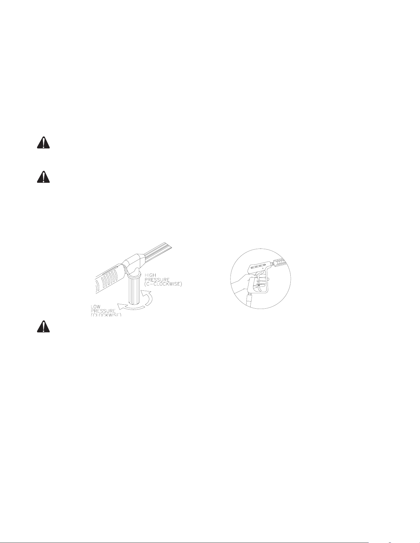
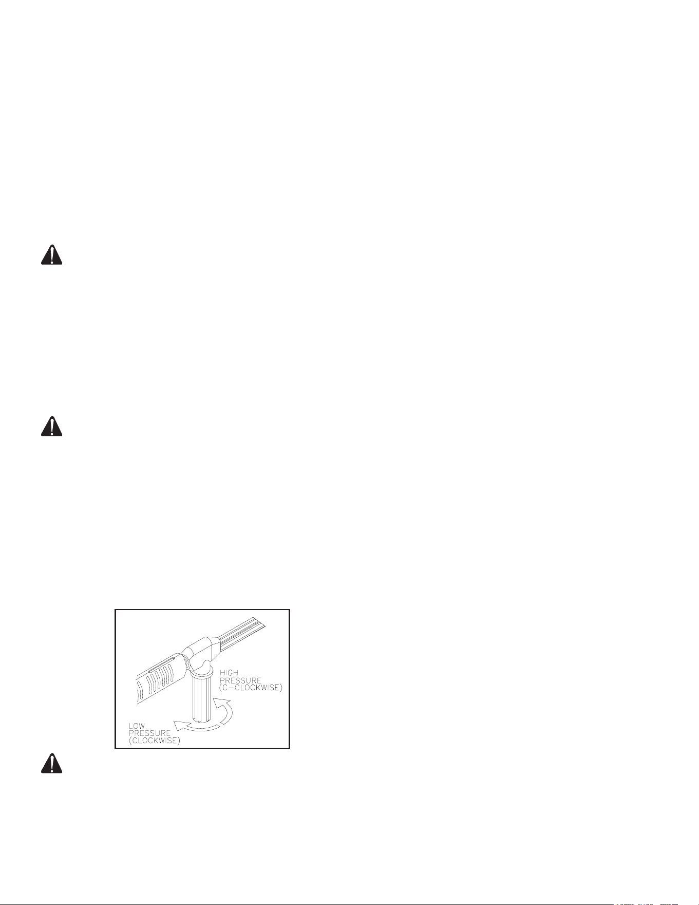
DUAL LANCE ASSEMBLY WITH ADJUSTABLE PRESSURE:
This unit features a dual lance assembly with adjustable pressure which allows the user to select a high or low pres-
sure spray. Simply rotate the adjustable grip on the dual lance to achieve the desired pressure selection.
1. Selection of high pressure can be achieved by turning the adjustable grip on the Dual Lance assembly counterclockwise.
2. Selection of low pressure can be achieved by turning the adjustable grip on the Dual Lance clockwise.
WARNING: RISK OF INJECTION CAUSING SEVERE INJURY! THE TRIGGER GUN SHOULD ALWAYS
BE LOCKED IN THE OFF POSITION WHEN NOT IN USE! NEVER LOOK DIRECTLY AT THE NOZZLE
UNLESS IT IS DISCONNECTED FROM THE TRIGGER GUN/DUAL LANCE ASSEMBLY!
INSTALLATION & PREPARATION
16 HMT-4004-0MGH Operator's Manual
QUICK-CONNECT NOZZLES:
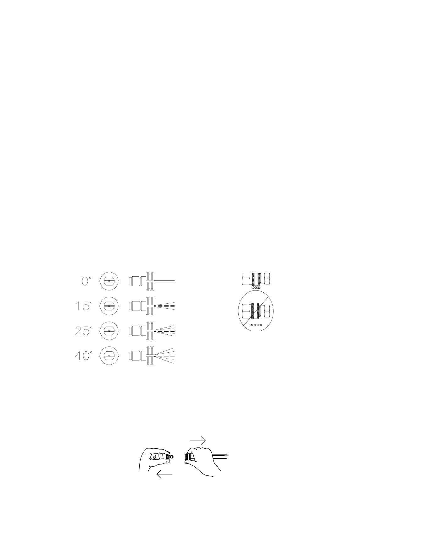
Various nozzles may be quick-connected into the end of the dual lance to change the spray pattern. The detergent
nozzle has been pre-installed at the factory. When using quick-connects (Q.C.), be certain the connection is securely
locked as shown at right. If not, the high pressure water may shoot the nozzle from the lance, causing severe injury
or serious damage. To determine spray fan, refer to the actual number stamped on the nozzle. The rst two digits
indicate the spray fan degree: 00=0°, 15=15°, 25=25°, 40=40°, 65=65°.
1. The 0° nozzle (RED):
This is a blasting nozzle. It delivers a very concentrated stream of water. Be cautious when using the straight narrow
stream. It is not recommended for use on painted or wood surfaces or items attached with adhesive backing. Uses:
Removing weeds from sidewalk cracks, stubborn stains from concrete, masonry, aluminum and steel, caked mud
from equipment, and cleaning lawn mower undersides.
2. The 15° nozzle (YELLOW):
This is a chiseling nozzle. The spray should be directed at a 45° angle to the surface and used like a scraper to
remove paint, grease and dirt. Uses: Surface preparation (removing mildew stains and paint chips).
3. The 40° nozzle (WHITE):
This is a wash nozzle. This wide spray pattern disperses the water pressure over a large area and is recommended
for moderate washing. Uses: Washing aluminum siding, cleaning windows, washing vehicles, spraying sidewalks,
driveways, and patios.
4. The 25° nozzle (GREEN):
This is a ushing nozzle. This pattern is best suited for ushing dirt, mud, and grime. Uses: Wet sweeping leaves
from walks, curbs and driveways, cleaning stable oors, washing swimming pool bottoms, degreasing engines.
5. The 65° nozzle: (included in dual lance.)
This is a detergent nozzle. The broad spray pattern distributes solution over vast areas. Uses: Detergent application,
misting or rinsing.
NOZZLE CONNECTION:
1. Ensure the trigger gun is locked in the OFF position.
2. Quick-connect nozzles can be connected or disconnected from the dual lance assembly by retracting the locking
ring on the quick-connect tting. When connecting the desired nozzle, push the locking ring over the quick connect
nozzle to secure connection.
INSTALLATION & PREPARATION
NOZZLES NOZZLE LOCK
NOZZLE CONNECTION
HMT-4004-0MGH Operator's Manual 17
WATER SUPPLY:
PRESSURIZED SUPPLY:
1. Select a water supply hose which is a quality grade of garden hose measuring at least ¾” ID and no longer than
50 feet.
2. Ensure the water strainer is clean and free of obstructions. If water ow becomes restricted to the pump, cavitation
can occur which will cause premature failure of the pump packings.
3. Connect one end of the water supply hose to the swivel with lter inlet and connect the other end to the pressurized
water supply.
NOTE: If there is a high mineral content in your water, it is recommended that a water softener be used to prevent the
possibility of excessive scale buildup inside the heat exchanger coil.
4. Follow the incoming water requirements listed below:
a. Water pressure must be between a minimum of 40 PSI and a maximum of 65 PSI.
b. Incoming GPM must be approximately one gallon more per minute than the outgoing GPM stated on the machine
nameplate. (You can check the GPM of yoursource by timing the lling of a 5 gallon container.)
c. Incoming water temperature must not exceed 125°F. Excessive pump damage may result if the water temperature
exceeds this level.
5. Never allow the unit to operate without the incoming water line attached and the water supply completely turned
on.
UNLOADER:
The unloader has been preset at the factory.
PRE-START INSPECTION PROCEDURES:
Before starting the unit, perform the following procedures:
1. Check the oil level in the pump.
2. Inspect the water inlet strainer. Clean or replace if necessary. See "Water Supply".
3. Check all hose connections to ensure they are securely tightened.
4. Inspect for system water leaks, oil leaks and fuel leaks. If a fuel leak is found, DO NOT START UNIT! See "Risk of
Explosion or Fire" warnings. Be sure that all damaged parts are replaced and that the mechanical problems are
corrected prior to operation of the unit. If you require service, contact Customer Service.
5. Inspect high pressure hoses for kinking, cuts and leaks. If a cut or leak is found, DO NOT USE HOSE! Replace
hose before starting unit. See "Risk of Injection" warnings.
6. Be sure that all damaged parts are replaced and that the mechanical problems are corrected prior to operation of
the unit. If you require service, contact Customer Service.
INSTALLATION & PREPARATION
END OF PREPARATION INSTRUCTIONS

18 HMT-4004-0MGH Operator's Manual
WARNING
THE FOLLOWING PAGES CONTAIN OPERATING INSTRUCTIONS.
DO NOT ATTEMPT TO TOW YOUR HOT WATER TRAILER UNTIL YOU HAVE READ AND
UNDERSTOOD ALL SAFETY PRECAUTIONS AND INSTRUCTIONS LISTED IN THIS MANUAL.
INCORRECT OPERATION CAN CAUSE SERIOUS INJURY!!
DO NOT ALTER OR MODIFY THIS EQUIPMENT
IN ANY MANNER!

HMT-4004-0MGH Operator's Manual 19
WHILE TOWING TRAILER:
WARNING: NEVER ALLOW A PERSON TO RIDE IN OR ON A TRAILER THAT IS BEING TOWED. ALL
STATES PROHIBIT PASSENGERS IN TOWED VEHICLES. A PERSON CAN FALL OFF AND BE STRUCK
BY ANOTHER VEHICLE OR RUN OVER BY THE TOWED TRAILER. FAILURE TO OBSERVE THIS
WARNING CAN RESULT IN DEATH.
SAFETY PRECAUTIONS DURING USE
Loading Trailer. The trailer should be loaded so that the downward tongue weight is approximately 10% of the gross
trailer weight. Hitch only to the hitch points recommended by the tow vehicle manufacturer.
Following and stopping distance. The stopping distance increases when towing a trailer. A rule of thumb for the
minimum distance that should be maintained between you and the preceding car on dry pavement is one car and
trailer length (2 car lengths) for every 10 MPH you are traveling. The distance should be increased accordingly de-
pending on road and weather conditions. Avoid sudden stops if possible. Operate tow vehicle smoothly - no jerky
turns, starts or stops. When possible, avoid operating the tow vehicle near ditches, embankments and holes and
reduce speed when crossing uneven or rough terrain.
Passing. Accelerating and passing should be done slowly to allow extra distance for passing. Signal well in advance
when passing and returning to the proper lane. Allow for the extra length of the trailer before changing lanes. Never
change lanes abruptly as this may cause the trailer to sway and push the tow vehicle into a "jack knife" condition.
Turning. Allow for the extra length of the trailer. Drive slightly beyond normal turning point to avoid running over
curbs and soft shoulders. Turning radius increases when towing. Reduce speed when turning, crossing slopes and
on rough, slick or muddy surfaces.
Uphill and Downhill Grades. Reduce speed and use a lower transmission gear for steep or long up or down hill
grades. Maintain safe distance from other vehicles.
Parking. When tow vehicle is idle, engage brakes and park lock securely.
• Avoid parking on uphill or downhill grades.
• Place transmission in "PARK".
• Apply parking brake.
• Use wheel chucks.
• In parking lot, avoid parking close to other vehicles. Turning radius is greater and it may be impossible
to get out of a parking space after a few other vehicles have parked around your vehicle.
ALWAYS TURN OFF TOW VEHICLE ENGINE BEFORE MAKING ADJUSTMENTS OR REPAIRS TO AN
ATTACHED TRAILER.
AFTER USE:
1. Inspect trailer for wear or damage.
2. Ensure that all fasteners and ttings are tight.
3. Verify the stop, tail and turn signals are working properly.
4. Check wires for good connections and possible fraying or wearing of insulation.
5. Check and properly maintain the trailer, hitch, jack, ball and coupler.
6. Inspect hitch and ball for damage. Ball or hitch can be damaged in parking, hitting curbs, dragging when crossing
ditches or railroad tracks.
7. Check and properly tighten all bolts on trailer, hitch, ball and coupler (including wheels).
8. Check safety chains for wear and do not allow them to drag on ground or roadway.
9. Check tow vehicle tires for wear and proper ination (check vehicle's owner manual for proper level of ination of
tires for towing a trailer).
10. Check trailer tires for wear and proper ination. Replace only with a tire of the same size and capacity ratings.
11. For proper tow vehicle maintenance while towing a trailer, check vehicle's owner manual and manufacturer's
specications.
OPERATING INSTRUCTIONS
20 HMT-4004-0MGH Operator's Manual
FLUSHING THE SYSTEM:
This unit has a steel coil which, after sitting, will cause the water remaining in the coil from the previous usage to
turn brown or black. This water must be ushed from the system before start-up. This procedure should be per-
formed WITHOUT the high pressure hose, gun and lance assembly installed.
1. Turn on the water supply.
2. Start engine on unit. Low pressure water will begin owing from the water outlet. This allows the unit to ush any
particles from the system. The unit is ushed when the water is clear.
3. Once the system is ushed, turn off engine and connect the high pressure hose to the water outlet of the unit.
4. Connect the trigger gun and dual lance assembly to the high pressure hose.
5. Install desired nozzle into dual lance assembly.
WARNING: CAUTION RISK OF UNIT DAMAGE. BE CERTAIN THE HOSE, GUN AND NOZZLE ASSEMBLY
ARE NOT CONNECTED TO THE UNIT WHILE FLUSHING THE SYSTEM. FLUSHING ALLOWS
MINERAL DEPOSITS TO BE RELEASED FROM THE SYSTEM WHICH WOULD OBSTRUCT OR
DAMAGE THE GUN AND NOZZLE ASSEMBLY RESULTING IN COSTLY REPAIRS.
START-UP/COLD WATER OPERATION:
1. Refer to the Safety Warnings before starting the machine.
2. Locate the Safety Decals on your unit and heed their warnings.
3. Ensure the Burner Switch is in the OFF position.
4. Pointing the trigger gun in a safe direction, unlock the trigger gun and squeeze the trigger. Hold the trigger gun
open while starting the engine according to the manufacturer’s instructions in the engine manual accompanying
the machine. Brace yourself for possible gun kickback when the engine starts.
WARNING: CAUTION RISK OF DAMAGE. DO NOT ALLOW SPRAY PATTERN TO REMAIN ON A FIXED
AREA FOR AN EXTENDED PERIOD OF TIME. POSSIBLE DAMAGE MAY OCCUR TO THE AREA.
5. Once the engine has started, perform the following procedures with the gun open:
a. Inspect for system water leaks, oil leaks, and fuel leaks. If a fuel leak is found, TURN MACHINE OFF IMMEDIATELY!
See “Risk of Explosion or Fire” warnings. Be sure that all damaged parts are replaced and that all mechanical
problems have been corrected prior to operation of the unit. Contact Customer Service if necessary.
b. Inspect high pressure hoses for kinks, cuts, and leaks. If a cut or leak is found, TURN MACHINE OFF
IMMEDIATELY! Replace hose before starting the machine. See “Risk of Injection” warnings. Be sure that all
damaged parts are replaced and that all mechanical problems have been corrected prior to operation of the
unit. Contact Customer Service if necessary.
6. The unit is now operating as a cold water pressure washer. Trigger the gun several times. Rotate adjustable grip
on the dual lance for high and low pressure application. NEVER place hand or ngers in front of the nozzle or look
directly into the nozzle!
DANGER RISK OF INJECTION CAUSING SEVERE INJURY! KEEP CLEAR OF NOZZLE! NEVER PLACE
HAND OR FINGERS IN FRONT OF NOZZLE! DO NOT DIRECT DISCHARGE STREAM AT PEOPLE OR
PETS!
7. Do not allow the machine to operate in the bypass mode (with the trigger gun closed) for more than three minutes
without triggering the gun. Failure to follow this simple rule can cause premature failure of the pump packings.
ADJUSTABLE GRIP
OPERATING INSTRUCTIONS

HMT-4004-0MGH Operator's Manual 21
OPERATING INSTRUCTIONS
HOT WATER OPERATION:
WARNING: RISK OF BURN! THE WATER TEMPERATURE COULD BECOME VERY HOT DURING HOT
WATER OPERATION. BE CAUTIOUS WHEN ADJUSTING PRESSURE OR CONTROLLING THE
TRIGGER GUN/LANCE ASSEMBLY.
1. Follow preceding steps 1-7 for “Start-up / Cold water operation”.
2. Move the Burner switch to the ON position.
3. Recheck the system for fuel leaks. If a fuel leak is found, TURN MACHINE OFF IMMEDIATELY! See “Risk of
Explosion or Fire” warnings. Be sure that all damaged parts are replaced and that all mechanical problems have
been corrected prior to operation of the unit. Contact Customer Service if necessary.
Note: Upon initial start-up, water will begin turning hot in approximately 20 seconds and will reach maximum
temperature within 2-1/2 minutes providing that the trigger gun remains open. The burner will not re when
the trigger is released.
SHUTDOWN:
1. Move the Burner switch to the OFF position.
2. Squeeze the trigger and discharge the water for a period of three minutes to cool the heat exchanger and high
pressure hose. Insufcient cool-down periods for the high pressure hose will cause excessive wear and eventual
rupture of the hose.
3. Do not close the choke to stop the engine. Backre or engine damage may occur.
4. Move the engine key switch to the OFF position.
5. Turn off the water supply and trigger the gun momentarily to relieve trapped pressure.
Disconnect and drain the high pressure hose, gun, and lance. Wipe the unit clean. Store in a non-freezing environ-
ment.
22 HMT-4004-0MGH Operator's Manual
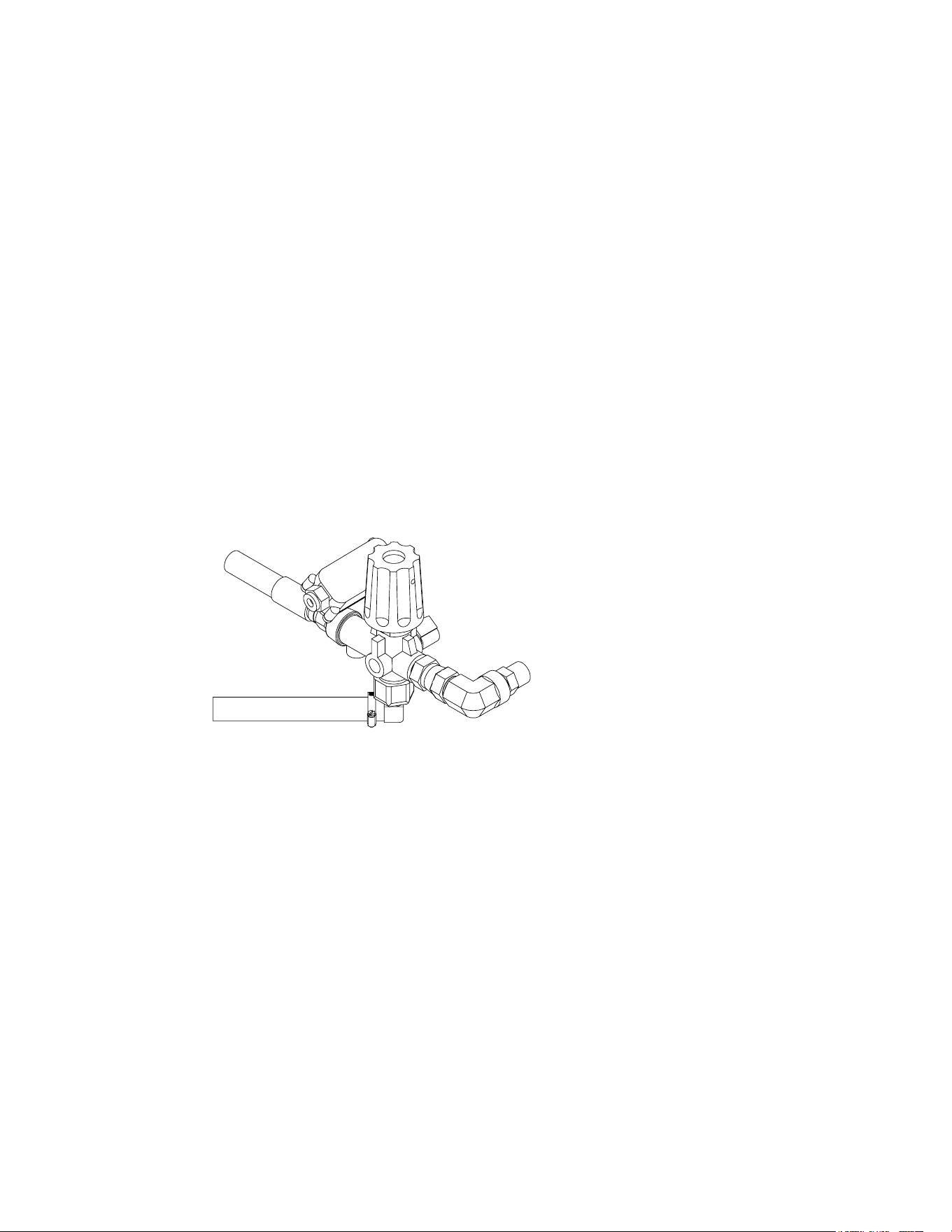
HIGH PRESSURE DETERGENT: (CLEANING WITH DETERGENTS)
NOTE: This feature is designed for use with mild detergents only. Since the cleaning solution travels through
various parts of the pressure washer, do not use corrosives as they will cause extensive damage as well as
pose a considerable safety hazard.
1. Refer to "Risk of Bodily Injury / Detergents". Be certain to wear protective safety attire as stated.
2. Prepare detergent solution according to label directions. (Never pump acids, alkalines, abrasive
fluids or solvents through the unit. Due to the unknown and often corrosive characteristics of many
detergents commonly used in the pressure washer cleaning industry, it is recommended to use only
mild detergents with this unit.)
3. With the trigger gun locked in the “OFF” position, securely quick-connect the detergent spray nozzle (#6540° BLACK)
into the end of the wand.
NOTE: This injection system is designed to apply detergents under low pressure only. It will not allow detergent
solutions to be introduced into the system unless the nozzle assembly is in the low pressure detergent mode.
4. Fully immerse the strainer end of the clear vinyl detergent hose into the detergent solution.
5. To apply solution; unlock the trigger gun and squeeze the trigger. In a few moments a detergent/water mixture will
exit the nozzle. Start spraying the lower portion of the surface being cleaned and move up, using long overlapping
strokes. Applying from the bottom up helps avoid streaking. Allow to soak briey. Avoid working on hot surfaces
or in direct sunlight to minimize the chances of the detergent drying, which may result in damaging surfaces. Be
certain to apply cleaning solution to a small section at a time.
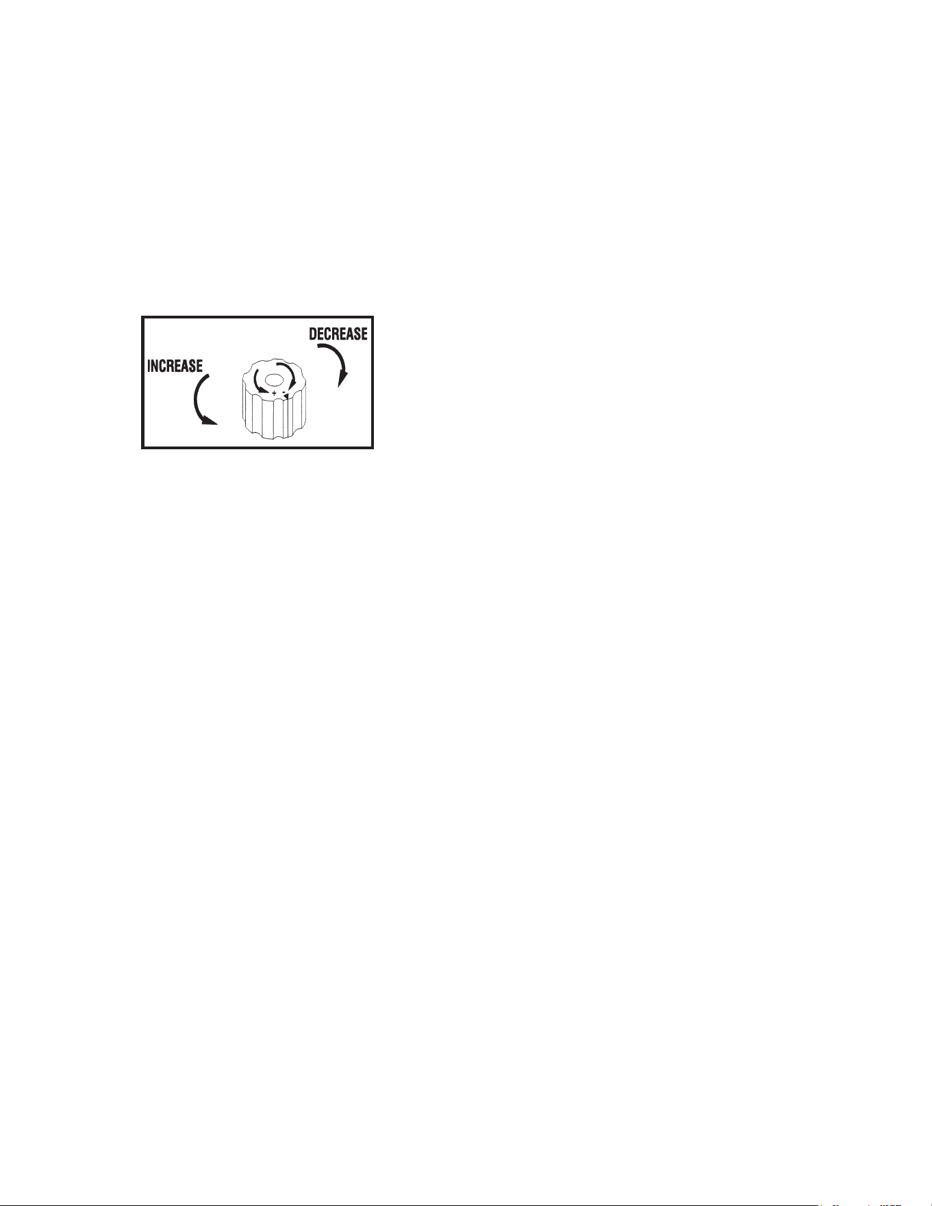
6. To rinse; lock the trigger gun in the "OFF" position. Turn the detergent metering valve to the "OFF" position. Unlock
the trigger gun and spray. It will take about 30 seconds to purge all detergent from the line. For best rinsing results,
start at the top and work down.
7. Siphon a gallon of water through the detergent injection system after each use. This prevents the possibility of
corrosion or detergent residue causing mechanical problems during the next use.
DETERGENT METERING VALVE
OPERATING INSTRUCTIONS
HMT-4004-0MGH Operator's Manual 23
SPECIFIC MAINTENANCE:
EVAPORATIVE EMISSION COMPONENTS:
The unit you have purchased includes the following components that are in compliance with ALL current California
Air Resources Board Evaporative Emission Standards;
1. Fuel Hose
2. Fuel Hose Fittings
These components should be inspected on a daily basis for cracks, leaks, and abnormal wear. If cracking, leaks or
abnormal wear has occurred, the components should be replaced immediately.
ENGINE: The engine instruction manual accompanying your unit lists the specic procedures for maintenance on the
engine. Following the engine manufacturer's recommendations will extend engine life.
PUMP: Change the pump oil after the rst 50 hours of operation. After initial change, the manufacturer recom-
mends changing the oil every three months or at 250 hour intervals. If oil appears dirty or milky, changes may be
required in greater frequency. Use SAE20 or 30 non-detergent pump oil and ll only to the center of the oil sight
glass. DO NOT overll.
NOZZLE: Water ow through the spray nozzle will erode the orice, making it larger, resulting in a pressure loss.
Nozzles should be replaced whenever pressure is less than 85% of the maximum. The frequency of replacement will
depend upon such variables as mineral content in the water and number of hours the nozzle is used.
MAINTENANCE-EVERY 3 MONTHS:
CHANGE WATER PUMP OIL: Ensure unit is off. Change the pump oil after the rst 50 hours of operation. After
initial change, every 3 months or 500 hour intervals are recommended. If oil appears dirty or milky, changes may
be required in greater frequency. Use SAE20 or 30 non-detergent pump oil and ll only to the center of the oil sight
glass. DO NOT overll.
REPLACE HIGH PRESSURE NOZZLE: Water ow through the spray nozzle will erode the orice, making it larger,
resulting in a pressure loss. Nozzles should be replaced whenever pressure is less than 85% of the maximum. The
frequency of replacement will depend upon such variables as mineral content in the water and number of hours the
nozzle is used.
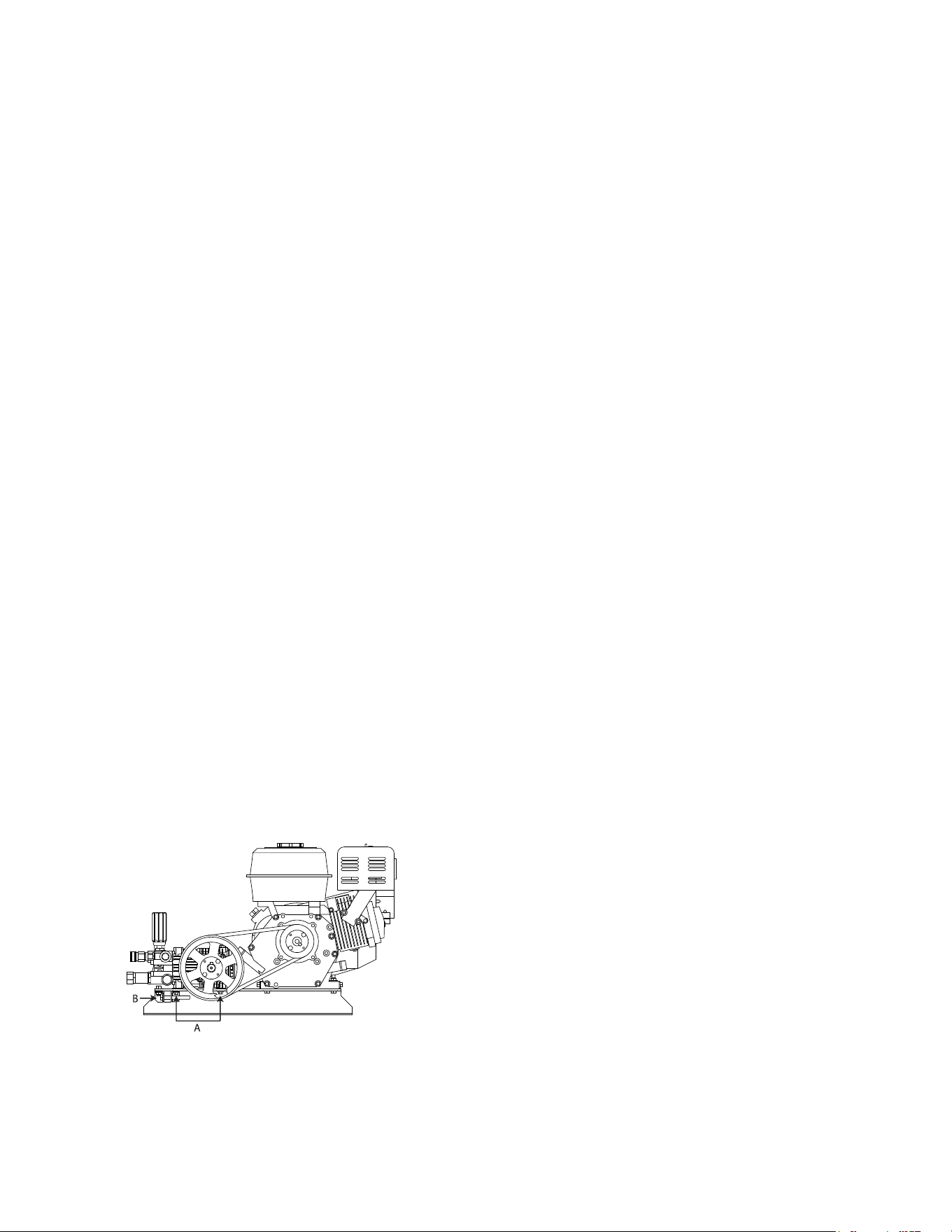
BELT INSPECTION: To maintain peak performance of your pressure washer, it may be necessary to adjust the belt
tension on occasion. Follow the procedure outlined below.
1. Remove the belt guard and loosen the four bolts on the pump (Reference A).
2. Turn the cap screw (Reference B) clockwise until a 1/2 inch belt deection is noticed between the pulleys.
3. Tighten the bolts. (Reference A)
4. Put a straight edge across both pulleys. If necessary, loosen one set of pulley screws and adjust in or out to properly
align. Tighten the pulley screws and check the tension again.
5. Replace the beltguard and tighten the fasteners securely.
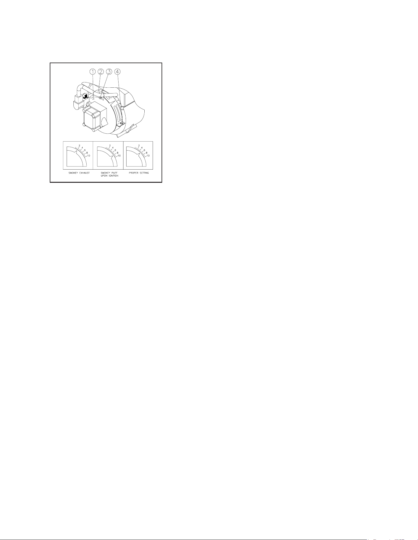
BURNER AIR ADJUSTMENT: The air shutter has been factory preset for proper operation between sea level and
2000 feet elevation at standard conditions (60°F ambient water and air temperatures). In colder temperatures or
higher altitudes, it may be necessary to adjust the air supply to the combustion chamber. This adjustment will maxi-
mize burner efciency and avoid inefcient operation or excessive sooting of the heat exchanger coil. A smoke spot
test is recommended during any air shutter and band adjustment. If you do not have the equipment to perform a
smoke spot test, follow the procedures listed below.
STORAGE & MAINTENANCE
BELT TENSION ADJUSTMENT
24 HMT-4004-0MGH Operator's Manual
STORAGE & MAINTENANCE
1. The machine must be running and the burner ON.
2. Loosen the Locking Screw (#3 at left) on the shutter.
3. Check for smoke from the heat exchanger exhaust. If smoke is not present, slowly close the Air Shutter (#1 at left)
by moving the dial counterclockwise to a lower number. Continue moving the dial until smoke appears.
4. Record this setting.
5. Open Air Shutter (#1 at left) two increments. Example: If Air Shutter was set at 2, move it to 4.
6. Slowly trigger the gun on and off. This will cause the burner to turn on and off. Look for a smoke puff when the
burner ignites.
7. Repeat steps 5 and 6 until a smoke puff is noticed. Record the Air Shutter Setting.
8. The difference between the recorded settings in steps 4 and 7 is the combustion window. Set the dial 1/2 way
between these settings.
NOTE: If you are unable to detect a setting on either step 3 or 7, more or less air may be needed to achieve a
proper combustion window. Loosen the Bolt (#4 at left) and open the Air Band (#2 at left) in 1/4" increments.
Repeat steps 3-8 until proper combustion window is achieved.
TEST WATER & FUEL PRESSURE: These procedures should be performed by an authorized service technician.
TEST WATER TEMPERATURE: This procedure should be performed by an authorized service technician.
MAINTENANCE – EVERY 6 MONTHS
REPLACE FUEL FILTER – Follow the instructions specied on the fuel lter for correct procedure.
MAINTENANCE – EVERY 12 MONTHS
DELIME COIL – A loss in pressure may signify that the coil needs to de delimed. Do this procedure on a periodic
basis.
1. Mix deliming powder/solution according to package directions.
2. Remove the nozzle from the wand. Place a nylon stocking over the wand assembly to collect debris, then place
the wand assembly into the oat tank.
3. Ensure the trigger gun is open and start the engine to allow water to circulate through the system. Allow process
to continue for 2-4 hours (Consult deliming agent package directions for exact time).
4. Once process is complete, turn off engine. Drain and clean the oat tank, remove the nylon stocking, and clean
the gun and wand assembly.
5. Flush the entire system with clean, fresh water and place the nozzle in the wand assembly.
6. Dispose of deliming solution according to local, state, and federal regulations.
TEST VOLTAGE AND AMP DRAW - Use a voltmeter and amp meter to test the machine for correct voltage and am-
perage. If you do not have these instruments or are unsure of how to perform these tests, this procedure should be
performed by an authorized service technician.
BURNER AIR ADJUSTMENT
HMT-4004-0MGH Operator's Manual 25
INSPECT BURNER FUEL PUMP INTERNAL FILTER – This procedure should be performed by an authorized service
technician.
CHECK BURNER ELECTRODES - This procedure should be performed by an authorized service technician.
REPLACE FUEL NOZZLE - This procedure should be performed by an authorized service technician.
MAINTENANCE-SEASONAL:
NOTE: Proper winterizing is based on the recommended manufacturer's instructions listed on the "Protection
Chart" shown on the back label of most antifreeze containers.
WINTERIZING: For storage and transportation purposes in subfreezing ambient temperatures, it will be necessary to
winterize this unit. This unit must be protected to the lowest incurred temperature for the following reasons:
WARNING: RISK OF UNIT BURSTING. DO NOT STORE / OPERATE UNIT IN A FREEZING ENVIRONMENT!
1. If any part of the pumping system becomes frozen; excessive pressure may build up in the unit which could cause
the unit to burst resulting in possible serious injury to the operator or bystanders.
2. The pumping system in this unit may be permanently damaged if frozen. FREEZE DAMAGE IS NOT COVERED BY
WARRANTY.
If you must store your unit in an area where the temperature may fall below 32°F, you can protect your unit by follow-
ing one of the procedures listed below.
AIR BLOWOUT:
1. Remove the nozzle from the wand assembly. Squeeze the trigger until water ceases to exit the wand assembly.
2. Connect an air tting from an air hose to the inlet swivel or strainer tting in the oat tank.
3. Run compressed air into the system to remove all water from the system.
ANTIFREEZE SOLUTION:
1. Gather the following items:
a. Two 5 gallon containers.
b. One gallon of antifreeze. (Mi-T-M® recommends an environmentally safe antifreeze.)
c. Water supply.
d. Three foot hose, 1/2-3/4 I.D. with a 3/4 inch male garden hose tting.
2. Procedure:
a. To start winterizing, unit must be run and primed according to the “Start-up Procedures” listed on page 14.
b. After running and priming, shut off the unit and water supply.
c. Relieve system pressure by pointing the trigger gun in a safe direction and squeezing the trigger until water
ow ceases to exit the nozzle.
d. Lock the trigger gun in an OFF position and remove the nozzle.
e. In one 5 gallon container, mix the antifreeze and water according to manufacturer’s
recommendations for the temperature to which you are winterizing.
NOTE: Proper winterizing is based on the recommended manufacturer’sinstructions
listed on the “Protection Chart” shown on the back label of most antifreeze con-
tainers.
f. Remove the water supply hose from the unit and attach the 3 foot hose securely to the
inlet connection. Submerge the other end into the antifreeze solution.
g. Point the wand into the empty container and start the unit.
h. Trigger the gun until the antifreeze begins to exit the wand. Release the trigger for 3 seconds, then trigger the
gun for 3 seconds. Continue cycling the gun several times until all the antifreeze mixture is siphoned from the
container.
i. Stop the unit.
j. Detach the 3 foot hose from the unit and drain any excess antifreeze back into the 5 gallon container.
k. Disconnect the hose/gun/wand assembly from the unit and drain any excess antifreeze back into the 5 gallon
container.
l. Store the hose, gun and wand with the unit in a safe, non-freezing area.
m. Store antifreeze solution for next use or dispose of according to state EPA laws.
STORAGE & MAINTENANCE
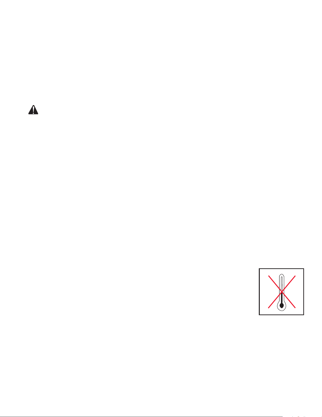
32˚F 0˚C

26 HMT-4004-0MGH Operator's Manual
TROUBLESHOOTING
SYMPTOM PROBABLE CAUSE REMEDY
Engine will not start. Engine problems. Refer to the Engine Manual accompanying your
unit.
Unit components are frozen. Allow to thaw. If any part of the unit becomes
frozen, excessive pressure may build up in the
unit which could cause the unit to burst result-
ing in possible serious injury to the operator or
bystanders.
No discharge at nozzle
when trigger mecha-
nism is squeezed.
Inadequate water supply. Ensure hose is 3/4" diameter and incoming water
supply is turned on.
Low or uctuating
pressure.
Kink in water inlet hose. Remove kink.
Water inlet screen obstructed. Remove screen, clean or replace.
Pump sucking air. (Prime eliminated) Tighten all water intake connections. Eliminate
leaks in intake line.
Eliminate leaks in intake line. Insert high pressure nozzle.
Obstructed or worn spray nozzle. Move adjustable grip on dual lance counter-
clockwise to high pressure.
Damaged or obstructed valve assy.on
pump.
Remove, clean or replace.
Pump packings worn. Remove, inspect, clean or replace. Replace
packings.
Unloader/bypass valve not operating
correctly.
Repair or replace.
Pump oil appears
milky or foamy.
Water in oil. Change pump oil. Fill to proper level.
Oil leaking from unit. Worn seals or o-rings. Contact Service Department.
Water is leaking at
safety relief valve.
Unloader malfunction. Detect and correct unloader problem.
Pressure switch malfunction. Detect and correct pressure switch problem.
Safety Relief Valve is defective. Replace safety relief valve. NEVER run unit
without safety relief valve. Doing so can cause
an explosion!
Water ows from the
nozzle when the trigger
gun is locked in the
OFF position.
Trigger gun is malfunctioning. Repair or replace.
Blower motor will not
run. (Burner will not
ignite without blower
running)
Burner/Blower motor malfunction. Repair or replace.

HMT-4004-0MGH Operator's Manual 27
TROUBLESHOOTING
SYMPTOM PROBABLE CAUSE REMEDY
Blower runs, but burner
will not ignite.
Trigger gun is closed. Open gun for pressure.
Out of fuel. Refuel.
Pressure switch override. Pressure should be over 375 PSI to allow burner
to come on.
No voltage. Consult Service Department.
Poor or improper fuel supply. Check fuel to ensure it is correct. Drain tank and
lter if necessary and rell with proper fuel.
Fuel pump sucking air. Tighten all fuel intake connections. Eliminate
leaks in intake line.
Blower runs, but
burner will not ignite.
Dirty or clogged fuel lter or fuel water
separator.
Drain or replace as necessary.
Low fuel pump pressure. Check fuel pump pressure, adjust or replace as
necessary.
Fuel pump inoperative. Check pressure, replace if necessary.
Flexible coupler broken. Replace
Fuel solenoid valve failure. Replace.
Dirty or clogged fuel nozzle. Replace fuel nozzle.
Improper burner air adjustment. Adjust as shown on pg. 23
Faulty ignition module. Repair or replace. Consult your Customer Ser-
vice.
Ignition electrodes damaged or worn. Adjust or replace electrodes. Consult your Cus-
tomer Service.
Blower runs, burner
ignites but will not heat
Poor or improper fuel supply. Check fuel to ensure it is correct. Drain tank and
lter if necessary and rell with proper fuel.
Dirty or clogged fuel lter or fuel water
separator.
Drain or replace as necessary.
Low fuel pump pressure. Check fuel pump pressure, adjust or replace if
needed.
Dirty or clogged fuel nozzle. Replace fuel nozzle.
Improper burner air adjustment. Adjust.
Scale build up in heat exchanger coil. Consult the Service Department.

28 HMT-4004-0MGH Operator's Manual
TROUBLESHOOTING
MAINTENANCE CHART TRAILER
SYMPTOM PROBABLE CAUSE REMEDY
Burner runs erratically. Water in the fuel oil. Replace fuel lter or drain fuel water separator,
drain fuel tank and replace with clean fuel.
Dirty fuel lter or fuel water separa-
tor.
Replace element.
Dirty fuel nozzle. Replace.
Improper air adjustment setting. Adjust
Fuel pump malfunctioning. Replace.
Low on fuel. Refuel. If white smoke persists consult the Ser-
vice Department.
Burner discharges
white smoke.
Excessive air supply. Adjust
Burner discharges
black smoke.
Insufcient air supply. Adjust.
Tire Air Pressure Inate to proper pressure indicated on sidewall. Every Trip
Wheel Lugs, Bolts and Nuts Tighten to proper torque specications. Every 3000 mi or 3 mos.*
Wheel Check for damage and or out-of-round. Every 6000 mi or 6 mos.
Coupler Ball Check for sufcient lube. Every Trip
Check lock mechanism.
Check for unusual wear.
Safety Chains at Hitch Ball Check for abrasion, distortion and general
integrity of links.
Every Trip
Coupler Check for proper fastening and hitch pin in
position and secure.
Every Trip
Load Distribution Check load distribution and security. Every Trip
Welds Check all weld beads for cracks or separations. Every 6000 mi. or 6 mos.
Electrical: Lights and Signals Check to make sure all are working properly.
Replace burned out bulbs.
Every trip
Axle Hubs, Bearings and
Seals
Check for hub wear, sufcient grease, exces-
sive play in bearings and leaking seals
Every 3000 mi or 3 mos.
*Check lug nuts for tightness before initial trip, at 25 miles, and 100 miles. Recheck at least every 3 months or
3000 miles.
HMT-4004-0MGH Operator's Manual 29
* Must be performed by an authorized service technician.
** Thepumpoilmustbechangedaftertherst50hoursofoperationandevery250hoursor3months,
whichevercomesrst.
*** High pressure nozzle should be replaced whenever pressure is less than 85%.
**** Scale buildup will vary with mineral content in the water and amount of usage. Descaling can range from
weekly to yearly maintenance.
***** Theengineoilmustbechangedaftertherst8hoursofoperationandevery50hoursor3months,which
evercomesrst.
MAINTENANCE CHART PRESSURE WASHER
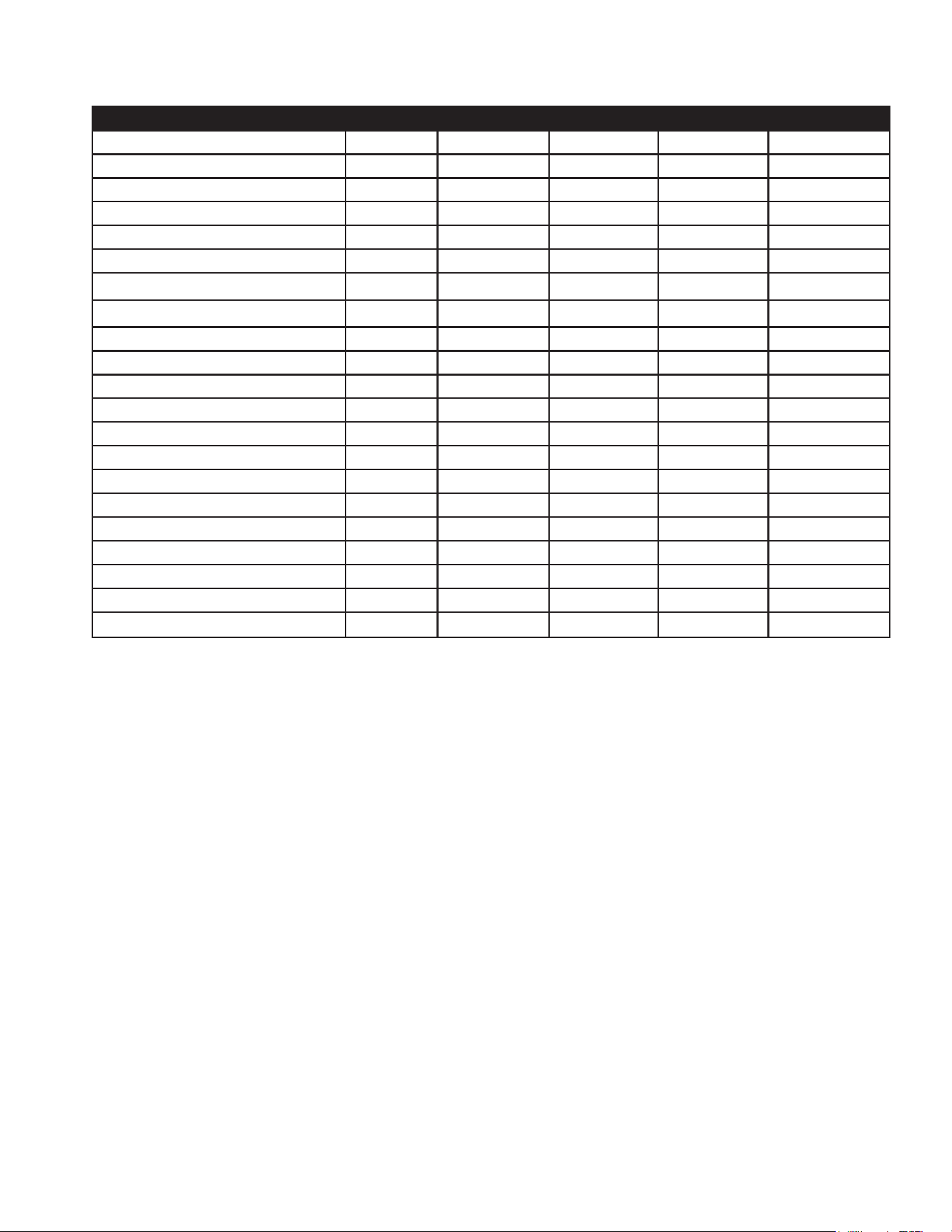
PROCEDURE DAILY 3 MONTHS 6 MONTHS 9 MONTHS 12 MONTHS
Check engine oil level
X
Change engine oil*****
X X X X
Check water pump oil level
X
Change water pump oil **
X X X X
Oil leak inspection
X
Fuel leak inspection
X
Water leak inspection
X
Hose inspection
X
Water inlet lter inspection
X
Check fuel lter
X X X X
Replace fuel lter
X X X
Inspect belts
X X X X
Replace high pressure nozzle***
X X X X
Inspect fuel pump lter*
X
Replace fuel nozzle*
X
Check burner air adjustment
X
Check burner electrodes*
X X X X
Test water pressure*
X
Test fuel pressure*
X X X X
Test water temperature*
X X X X
Descale coil****
X X X X

30 HMT-4004-0MGH Operator's Manual
STATEMENT OF WARRANTY
Manufacturer warrants all parts (except those referred to below) of your new pressure washer to
be free from defects in materials and workmanship during the following periods:
For Lifetime:
Pump Manifold
For Ten (10) Years from the date of original purchase:
High Pressure Pump (General Pump Only)
For Seven (7) Years from the date of original purchase:
High Pressure Pump (AR Pump Only)
For Five (5) Years from the date of original purchase:
Heat Exchanger Coil
For Two (2) Years from the date of original purchase:
Frame Burner
Guards or Shields Pulleys
Plumbing
For Six (6) Months from the date of original purchase:
Burner Motor Ignition Transformer
For Ninety (90) days from the date of original purchase:
Control Switches Safety Switches
Unloader Valve Fuel Pump
Capacitor
For Thirty (30) days from the date of original purchase:
High Pressure Hose Trigger Gun
Strainer/Filters
Defective parts not subject to normal wear and tear will be repaired or replaced at
Manufacturer's option during the warranty period. In any event, reimbursement is limited to the
purchase price paid.
EXCLUSIONS
1. Engine/Motor are covered under separate warranty by its respective manufacturer and is
subject to the terms set forth therein.
2. Normal wear parts:
Pump Packings Spray Nozzles
Pump Valves Quick Connectors
Detergent Valves Fuel Filters
3. This warranty does not cover parts damaged due to normal wear, misapplication, misuse,
operation at other than recommended speeds, pressures or temperature. Parts damaged or
worn because of the use of caustic liquids or by operation in abrasive or corrosive environments
or under conditions causing pump cavitation are not warranted. Failure to follow recommended
operating and maintenance procedures also voids warranty.
4. The use of other than genuine parts will void warranty. Parts returned, prepaid to the
manufacturer's factory or to an Authorized Service Center will be inspected and replaced free of
charge if found to be defective and subject to warranty. There are no warranties which extend
beyond the description of the face hereof. Under no circumstances shall the manufacturer bear
any responsibility for loss of use of the unit, loss of time or rental, inconvenience, commercial
loss or consequential damages.

HMT-4004-0MGH Operator's Manual 31
CALIFORNIA EVAPORATIVE EMISSIONS CONTROL WARRANTY STATEMENT
YOUR WARRANTY RIGHTS AND OBLIGATIONS
The California Air Resources Board and the manufacturer are pleased to explain the emission control system’s warranty on your
2022/2023 small off-road engine/equipment (SORE). In California, new equipment that use small off-road engines must be designed,
built and equipped to meet the State’s stringent anti-smog standards. The manufacturer must warrant the evaporative emissions control
system (EECS) on your SOREs for the period listed below provided there has been no abuse, neglect or improper maintenance of your
equipment leading to the failure of the evaporative emission control system.
Your EECS may include parts such as the carburetor, fuel tanks, fuel lines (for liquid fuel and fuel vapors), fuel caps, valves,
canisters, filters, clamps, connectors, and other associated components. Where warrantable conditions exist, the manufacturer will
repair your small off-road engine at no cost to you including diagnosis, parts and labor.
MANUFACTURER’S WARRANTY COVERAGE:
This EECS is warranted for two years. If any evaporative emissions-related part on your small off-road engine/equipment is
defective, the part will be repaired or replaced by the manufacturer.
OWNER’S WARRANTY RESPONSIBILITIES:
-As the SORE owner, you are responsible for performance of the required maintenance listed in your owner’s manual. The
manufacturer recommends that you retain all receipts covering maintenance on your SORE , but the manufacturer cannot deny
warranty coverage solely for the lack of receipts.
-As the SORE owner, you should be aware that the manufacturer may deny you warranty coverage if your SORE or a part has
failed due to abuse, neglect, or improper maintenance or unapproved modifications.
-You are responsible for presenting your SORE to distribution center or service center authorized by the manufaturer, 50 Mi-T-M
Drive, Peosta, IA 52068 (herein Mi-T-M) as soon as the problem exists. The warranty repairs shall be completed in a reasonable
amount of time, not to exceed 30 days.
If you have a question regarding your warranty coverage, you should contact Customer Service Department at 1-800-553-9053 or
by emailing us at corp@mitm.com.
GENERAL EMISSIONS WARRANTY COVERAGE
- CALIFORNIA ONLY -
The manufacturer warrants to the ultimate purchaser and each subsequent purchaser that the SORE (1) has been designed, built
and equipped so as to conform with all applicable regulations; and (2) is free from defects in materials and workmanship that cause the
failure of a warranted part to conform with those regulations as may be applicable to the terms and conditions stated below.
(a) The warranty period begins on the date the engine is delivered to an ultimate purchaser or first placed into service. The warranty
period is two years.
(b) Subject to certain conditions and exclusions as stated below, the warranty on emissions related parts is as follows:
(1) Any warranted part that is not scheduled for replacement as required maintenance in your owner’s manual is warranted for
the warranty period stated above. If the part fails during the period of warranty coverage, the part will be repaired or replaced by
the manufacturer according to subsection (4) below. Any such part repaired or replaced under warranty will be warranted for the
remainder of the period.
(2) Any warranted part that is scheduled only for regular inspection in your owner’s manual is warranted for the warranty period
stated above. Any such part repaired or replaced under warranty will be warranted for the remaining warranty period.
(3) Any warranted part that is scheduled for replacement as required maintenance in your owner’s manual is warranted for the
period of time before the first scheduled replacement date for that part. If the part fails before the first scheduled replacement, the
part will be repaired or replaced by the manufacturer according to subsection (4) below. Any such part repaired or replaced under
warranty will be warranted for the remainder of the period prior to the first scheduled replacement point for the part.
(4) Repair or replacement of any warranted part under the warranty provisions herein must be performed at a warranty station at
no charge to the owner.
(5) Not withstanding the provisions herein, warranty services or repair will be provided at all of our distribution centers that are
franchised to service the subject engines.
(6) The owner must not be charged for diagnostic labor that leads to the determination that a warranted part is in fact defective,
provided that such diagnostic work is performed at a warranty station.
(7) Throughout the engine warranty period stated above, the manufacturer will maintain a supply of warranted parts sufficient to
meet the expected demand for such parts.
(8) Any replacement parts that do not increase the exhaust or evaporative emissions of the engine or evaporative emission
control system must be used in the performance of any warranty maintenance or repairs and must be provided without charge to
the owner. Such use will not reduce the warranty obligations of the manufacturer.
(9) Add-on or modified parts that are not exempted by the Air Resources Board may not be used. The use of any non-exempted
add-on or modified parts by the ultimate purchaser will be grounds for disallowing a warranty claims. The manufacturer will not
be liable to warrant failures of warranted parts caused by the use of a non-exempted add-on or modified part.

32 HMT-4004-0MGH Operator's Manual
(10) The manufacturer shall provide any documents that describe that the manufacturer’s warranty procedures or policies within
five working days of request by the Executive Officer.
(c) WARRANTED PARTS:
The repair or replacement of any warranted part otherwise eligible for warranty coverage may be excluded from such warranty
coverage if the manufacturer demonstrates that the engine has been abused, neglected, or improperly maintained, and that such
abuse, neglect, or improper maintenance was the direct cause of the need for repair or replacement of the part. That
notwithstanding, any adjustment of a component that has a factory installed, and properly operating, adjustment limiting device is
still eligible for warranty coverage. The following emissions warranty parts list are covered.
(1) Fuel Tank*
(2) Fuel Cap
(3) Fuel Lines (for liquid fuel and fuel vapors)
(4) Fuel Line Fittings
(5) Clamps*
(6) Pressure Relief Valves*
(7) Control Valves*
(8) Control Solenoids*
(9) Electronic Controls*
(10) Vacuum Control Diaphragms*
(11) Control Cables*
(12) Control Linkages*
(13) Purge Valves*
(14) Gaskets*
(15) Liquid/Vapor Separator
(16) Carbon Canister
(17) Canister Mounting Brackets
(18) Carburetor Purge Port Connector
* Note: As they relate to the evaporative emission control system.

Manual del operador 35
ADVERTENCIA: Este producto puede
exponerlo a productos químicos, incluido el
plomo, que el Estado de California conoce a
causar cáncer y defectos congénitos u otros
daños reproductivos. Para obtener más
información, visite www.P65Warnings.ca.gov
ADVERTENCIA
ADVERTENCIA: Este producto puede expo-
nerle a químicos incluyendo carbon monoxide,
que es conocido por el Estado de California
como causante de defectos de nacimiento u
otros daños reproductivos. Para mayor
información, visite www.P65Warnings.ca.gov.
ADVERTENCIA
INTRODUCCIÓN ........................................................................................................................................36
¡IMPORTANTE! ..........................................................................................................................................36
ADVERTENCIAS DE SEGURIDAD .............................................................................................................37
HMT-4004-0MGH CARACTERÍSTICAS .....................................................................................................43
INSTALACIÓN Y PREPARACIÓN ...............................................................................................................44
ADVERTENCIA ..........................................................................................................................................51
INSTRUCCIONES DE OPERACIÓN .......................................................................................................... 52
ALMACENAJE Y MANTENIMIENTO ..........................................................................................................56
LOCALIZACION DE FALLAS ...................................................................................................................... 59
TABLA DE MANTENIMIENTO DEL REMOLQUE ........................................................................................62
TABLA DE MANTENIMIENTO ....................................................................................................................63
36 Manual del operador
INTRODUCCIÓN
¡Felicitaciones por la compra de su nueva lavadora a presión! Puede estar seguro que su lavadora a presión fue
construida con el nivel más alto de precisión y exactitud. Cada componente ha sido probado rigurosamente por
técnicos para asegurar la calidad, la resistencia y el rendimiento de esta unidad. Con más de veinte años de experi-
encia en la construcción de lavadoras a presión, usted ha tomado una sabia decisión en seleccionar una lavadora a
presión.
Este manual del operador fue compilado para su benecio. Leyendo y siguiendo los pasos simples de seguridad,
instalación, operación, mantenimiento y localización de fallas descritos en este manual ayudará a prolongar aun
más la operación libre de fallas que usted puede esperar de su nueva lavadora a presión. El contenido de este
manual está basado en la información actualizada disponible al momento de la publicación. Fabricante se reserva el
derecho de efectuar cambios en precio, color, materiales, equipo, especicaciones o modelos en cualquier momen-
to sin previo aviso.
¡IMPORTANTE!
Estos párrafos están rodeados por una “CASILLA DE ALERTA DE SEGURIDAD”. Esta casilla se usa para designar
y enfatizar las Advertencias de Seguridad que deben seguirse al operar esta lavadora a presión. Acompañando
a las Advertencias de Seguridad están las “palabras de alerta” que designan el grado o nivel de seriedad de
riesgo. Las “palabras de alerta” usadas en este manual son las siguientes:
PELIGRO: Indica una situación inminente riesgosa la cual, si no se evita, RESULTARA en la muerte o en
lesiones graves.
ADVERTENCIA: Indica una situación potencialmente riesgosa la cual, si no se evita, PODRIA resultar en
la muerte o en lesiones graves.
PRECAUCION: Indica una situación potencialmente riesgosa la cual, si no se evita PUEDE resultar en
lesiones menores o moderadas.
El símbolo indicado a la izquierda de este párrafo es el “Símbolo de Alerta de Seguridad”. Este símbolo se usa
para alertarlo acerca de artículos o procedimientos que podrían ser peligrosos para usted u otras personas
usando este equipo.
PROVEA SIEMPRE UNA COPIA DE ESTE MANUAL A CUALQUIER PERSONA QUE USE ESTE EQUIPO. LEA TODAS
LAS INSTRUCCIONES ANTES DE OPERAR ESTA LAVADORA A PRESION, OBSERVANDO EN PARTICULAR LAS
“ADVERTENCIAS DE SEGURIDAD” PARA EVITAR LA POSIBILIDAD DE LESIONES PERSONALES AL OPERADOR.
Escriba el número de serie de su unidad en el espacio provisto abajo, una vez que la unidad haya sido desempaca-
da.
NUMERO DE SERIE___________________________
Inspeccione por daño el contenido de la caja. Si algo parece dañado, NO LA DEVUELVA AL LUGAR DE COMPRA.
Llame a su representante de servicio al cliente.
Por favor tenga disponible la información siguiente para todas las llamadas de servicio:
1. Número de modelo
2. Número de serie
3. Fecha y lugar de compra
Manual del operador 37
RIESGO
DE EXPLOSIÓN O INCENDIOV
ADVERTENCIAS DE SEGURIDAD
Lea todas Las advertencias de seguridad antes de usar la lavadora a presión.
PELIGRO
POSIBLE CONSECUENCIA
PREVENCIÓN
Pueden ocurrir lesiones graves o
fatales ocasionadas por chispas
normales en las fuentes de ignición
múltiples o en el escape del motor y
del quemador.
Pueden ocurrir lesiones graves o
fatales como consecuencia de un
procedimiento inadecuado al reabas-
tecer de combustible.
Siempre opere la lavadora en una área bien venti-
lada libre de vapores inamables, polvo combus-
tible y gases o materiales combustibles.
No almacene la lavadora a presión cerca de una
llama abierta o equipo como hornos, calefac-
tores, calentadores de agua, etc., que usen
una llama piloto o dispositivo de encendido por
chispa.
¡No use esta lavadora a presión para atomizar
material inamable!
No fume mientras llene los tanques de combus-
tible.
Nunca llene los tanques de combustible mien-
tras el motor aún esté en marcha o esté caliente.
Permita que el motor se enfríe dos minutos antes
de volver a cargar combustible.
No llene los tanques de combustible en interiores
o en una área con poca ventilación.
Siempre vierta el combustible lentamente para
evitar la posibilidad de un derrame, lo cual podría
provocar un incendio.
Tanque de combustible del motor:
Si se usa un motor de gasolina, llene únicamente
con gasolina. No use diesel ni petróleo o aceite
combustible.
Tanque de combustible del quemador:
Al llenar el tanque de combustible del quemador,
use aceite de combustible diesel o queroseno
No.1 ó No.2. No use gasolina, drenajes de cigüe-
nal, o aceite que tiene gasolína o solventes.
No opere la unidad si se derrama gasolina o
combustible de diesel. Con un paño, limpie
completamente la lavadora a presión y aléjela
del derrame. Evite crear cualquier ignición hasta
que el combustible de gasolina o diesel se haya
evaporado.
Cuando la batería está activando la batería tiene
gases de hidrógeno y oxígeno que son muy
explosivos. No tenga chipas abiertas o ames
cerca de batería nunca, especialmente cuando
cargando la batería.
Antes de servicando, asegúrese de que desco-
nectar teminal de tierra de la batería. Cuando
desconectando cáble de la batería, empezar con
terminal negativo, y cuando las contectando,
empezar con el positivo cable.
Quitar bombas de rejilla de ventilación de la bat-
ería, cuando cargando la batería.
Use contador de voltio o hidrocantador para
controlar la carga de la batería.
No hacer arrancar la batería a menos que las dos
baterías tener voltaje igual y amperio igual.
Pueden ocurrir lesiones graves o fatales
de la batería.
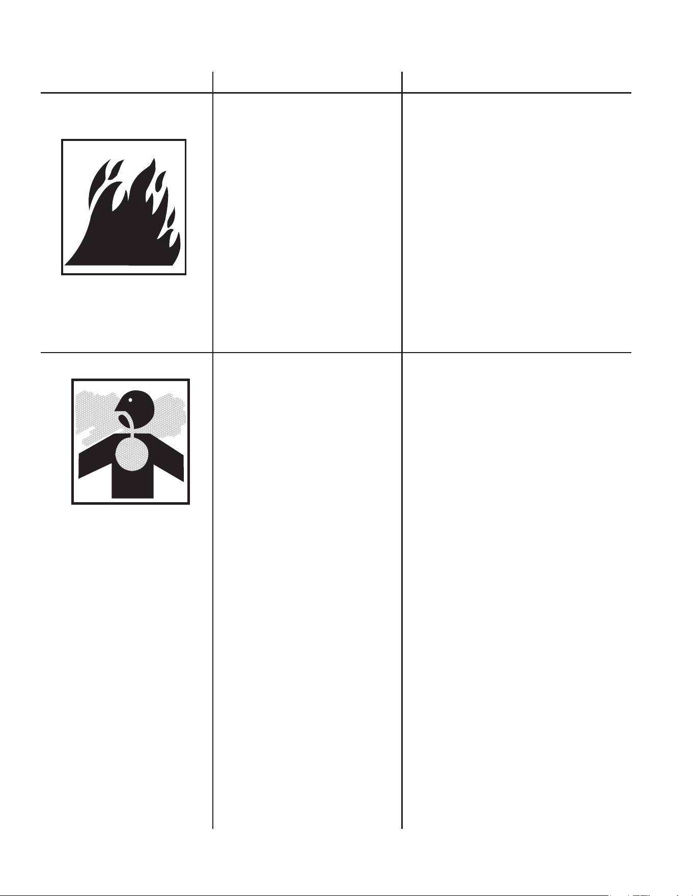
38 Manual del operador
RIESGO DE ASFIXIA
RIESGO
DE INCENDIO
ADVERTENCIAS DE SEGURIDAD
Lea todas Las advertencias de seguridad antes de usar la lavadora a presión.
Pueden sufrirse lesiones graves o
fatales como consecuencia de la
inhalación de gases del escape del
motor/quemador o vapores peligro-
sos. El gas que emana del escape de
este producto contiene substancias
químicas identicadas por el Estado
de California como agentes que pro-
vocan cáncer, defectos de nacimiento
o daños reproductivos.
Es necesario para agregar un arrestador de
chispas en el moee de este motor cuando
usar con tierra que tener algo cultivo agrícola
amable (heno o grano), y si usarlos en o cerca
de broza o areas forestales. El operador tiene
que mantener el arrestador en order efec-
tuar. En el estado de California, lo anterior es
obligatorio por ley. (Sección 4442 del Código
de Recursos Públicos de California). Otros es-
tados quizá tengan leyes similares. En terrenos
federales se aplican las leyes federales.
Esta lavadora a presión tiene un dispositivos
de seguridad aparato que nunca deben ser
alterados, modicados, extraídos o desco-
nectados. Si falla el dispositivo, reemplácelo
inmediatamente con un repuesto genuino del
fabricante.
Esta lavadora a presión fue diseñada para uso
externo únicamente. Nunca opere esta lava-
dora a presión en una área cerrada. Siempre
asegúrese de que exista ventilación adecuada
(aire externo fresco) para la respiración y la
combustión. Esto impedirá la acumulación de
gases peligrosos de monóxido de carbono.
Tenga cuidado en las áreas de poca venti-
lación, o áreas con ventiladores de extracción
que pueden provocar un intercambio deciente
de aire.
Obedezca todas las instrucciones proporcio-
nadas con los materiales que está rociando.
Quizá sea necesario usar un respirador cuando
se trabaje con ciertos materiales. No use esta
lavadora a presión para distribuir detergentes
peligrosos.
Pueden ocurrir lesiones graves o fatales
como consecuencia de un incendio al
ras de tierra ocasionado por una chispa
del silenciador.
Pueden ocurrir lesiones graves o fatales
si no se mantienen correctamente los
dispositivos de seguridad del sistema.
PELIGRO
POSIBLE CONSECUENCIA
PREVENCIÓN
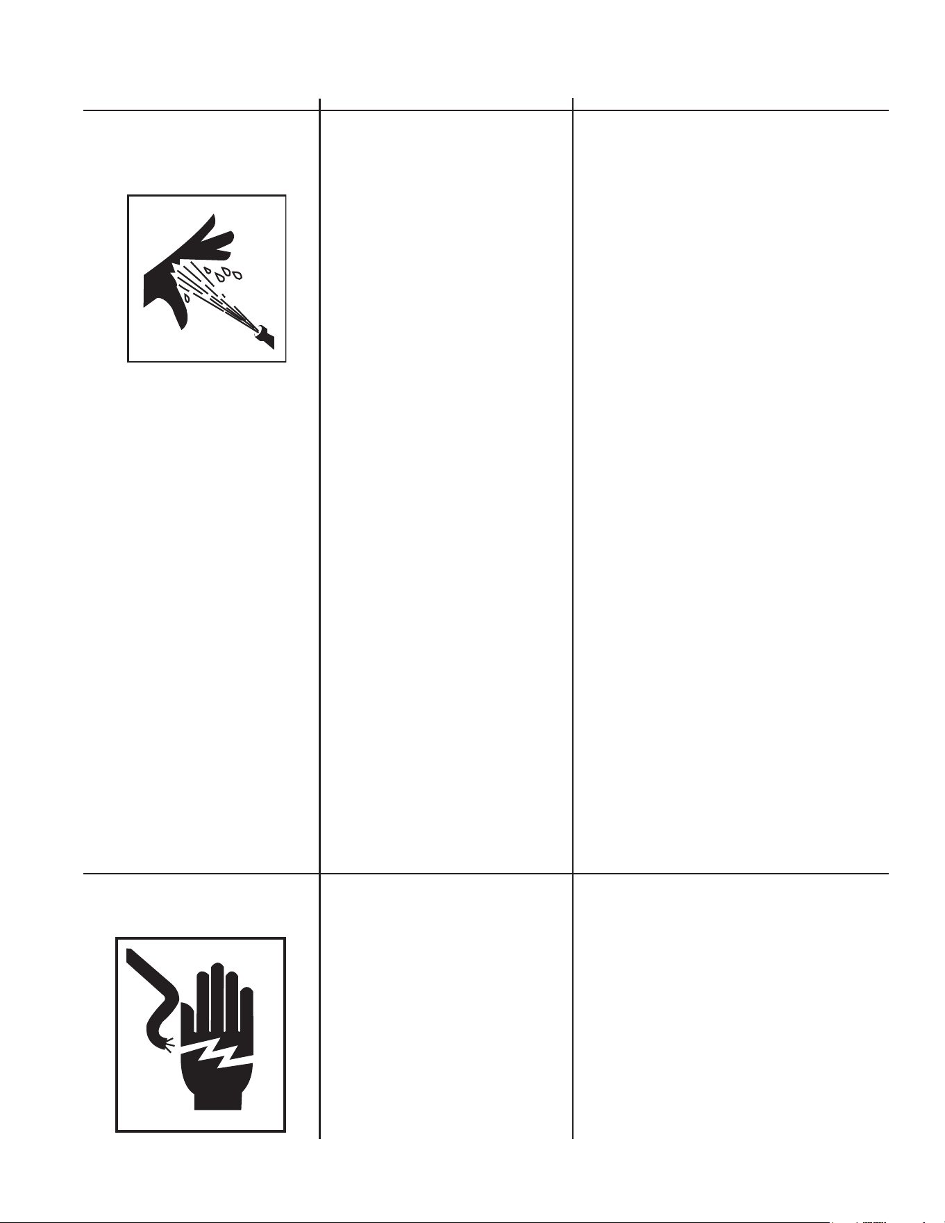
Manual del operador 39
¡Manténgase completamente alejado de la bo-
quilla y el atomizador! Nunca coloque la mano,
los dedos o el cuerpo directamente sobre la
boquilla de rocío.
Nunca apunte el atomizador alta presión hacia
usted mismo o hacia otra persona. Solamente
operadores calicados usan este equipo.
Siempre mantenga el área de trabajo despe-
jada de personas.
NO PERMITA que algún niño opere esta
unidad.
¡BUSQUE ATENCIÓN MÉDICA DE EMERGEN-
CIA si parece que el rocío ha penetrado la piel!
¡No lo trate como una simple cortadura!
Debe inspeccionar diariamente las mangueras
de alta presión y las líneas de combustible
para buscar señales de desgaste. Si hay
evidencia de falla, reemplace inmediatamente
todas las mangueras y líneas de combustible
sospechosas para prevenir la posibilidad de
lesiones por el rocío a alta presión. Si una
manguera o conexión tiene alguna fuga, NO
COLOQUE SU MANO DIRECTAMENTE SO-
BRE LA FUGA.
NUNCA opere la pistola con el gatillo jado en
la posición abierta. Para prevenir una descarga
accidental, la pistola debe tener bien trabado
el seguro del gatillo cuando no se encuentre
en uso.
Antes de retirar la boquilla de rocío o dar
servicio a la unidad, apague la unidad y tire del
gatillo de la pistola para liberar la presión. (Aun
cuando apague la unidad, todavía quedará
agua a alta presión en la bomba, la manguera
y la pistola hasta que la libere jalando el gatillo
de la pistola.)
Pueden sufrirse lesiones graves o fa-
tales como consecuencia de la atom-
ización a alta presión con penetración
en la piel.
RIESGO DE INYECCIÓN O
LESIÓN POR CORTADURA
SEVERA
RIESGO DE
ELECTROCUCIÓN O
CHOQUE ELÉCTRICO
Pueden sufrirse lesiones graves o
fatales debido al contacto con la
electricidad.
¡NO dirija el rocío hacia instalaciones eléctricas
de ninguna clase! Esto incluye tomas eléctricas,
lámparas, cajas de fusibles, transformadores, la
unidad misma, etc.
NO permita que los componentes de metal de
la lavadora a presión entren en contacto con
componentes eléctricos cargados.
ADVERTENCIAS DE SEGURIDAD
Lea todas Las advertencias de seguridad antes de usar la lavadora a presión.
PELIGRO
POSIBLE CONSECUENCIA
PREVENCIÓN
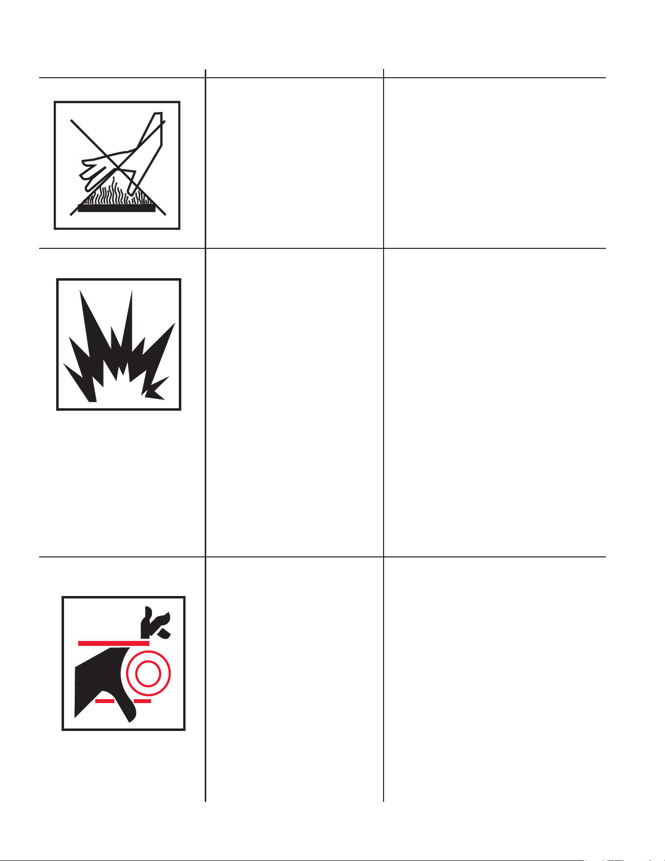
40 Manual del operador
RIESGO DE QUEMADURAS
Pueden producirse lesiones graves si
se toca el motor de gasolina, el silen-
ciador o el intercambiador de calor.
Estas áreas pueden permanecer
calientes por algún tiempo después
de que se ha apagado la lavadora a
presión.
Pueden producirse lesiones graves
debido al mal funcionamiento de la
lavadora a presión o la explosión de
accesorios si se usan componentes,
aditamentos o accesorios que no cor-
respondan al sistema.
Pueden producirse lesiones graves o
fatales si se intenta arrancar la lava-
dora a presión cuando esté conge-
lada la bomba.
Nunca haga ajustes a las presiones conguradas
en la fábrica.
Nunca exceda la máxima graduación de presión
de los accesorios permitida por el fabricante.
No permita que alguna de las mangueras haga
contacto con el silenciador del motor, el motor
de gasolina o el intercambiador de calor para
prevenir la posibilidad de explosión. No arrastre
las mangueras sobre supercies abrasivas como
el cemento.
Solo use las partes de reparación para su lava-
dora a presión recomendadas por el fabricante.
En temperaturas de congelación, la unidad siem-
pre deberá permanecer lo sucientemente cali-
ente como para asegurar que no haya formación
de hielo en la bomba. No arranque la lavadora
a presión si ha sido transportada en un vehículo
abierto o de calefacción deciente, sin primero
permitir que la unidad se descongele.
RIESGO DE EXPLOSIÓN
Antes de hacer cualquier ajuste, asegúrese de
que el motor esté apagado y que el cable o los
cables de ignición estén separados de las bujías
de ignición. Al voltear la máquina manualmente
durante el ajuste o la limpieza puede arrancar el
motor y junto con él, la máquina.
No opere la unidad sin que todas las cubiertas
protectoras se encuentren en su lugar.
Nunca permita que ninguna parte de su cuerpo
haga contacto con el motor de gasolina, el silen-
ciador o el intercambiador de calor.
El operador puede sufrir de lesio-
nes graves si hace contacto con las
partes en movimiento de la lavadora a
presión.
RIESGO POR PARTES EN
MOVIMIENTO
ADVERTENCIAS DE SEGURIDAD
Lea todas Las advertencias de seguridad antes de usar la lavadora a presión.
PELIGRO
POSIBLE CONSECUENCIA
PREVENCIÓN
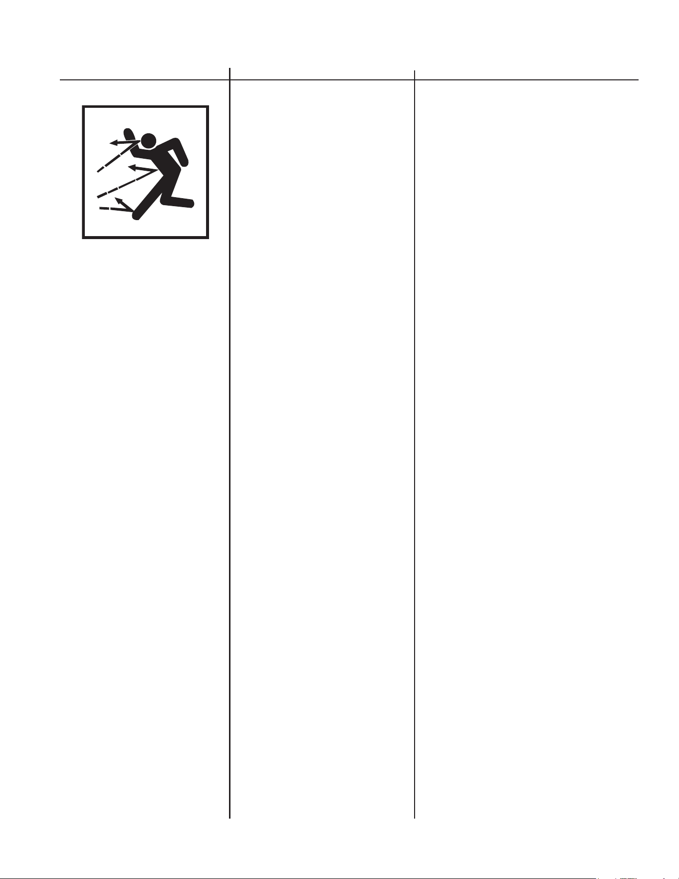
Manual del operador 41
RIESGO DE LESIONES
Pueden ocurrir lesiones graves o
fatales si los detergentes entran en
contacto con la piel.
Pueden ocurrir lesiones graves
provocadas por partículas sueltas
proyectadas a gran velocidad a través
la pistola atomizadora.
Pueden ocurrir lesiones si el operador
pierde el equilibrio causado por el im-
pulso del agua que está atravesando
la boquilla de rocío.
¡BUSQUE ATENCIÓN MÉDICA DE EMERGEN-
CIA si está usando agentes de limpieza y siente
que el rocío ha penetrado la piel! ¡NO LO TRATE
COMO UNA SIMPLE CORTADURA! Lea la hoja
de datos de seguridad del material (MSDS)
proporcionada con su detergente para estar
preparado y poder informar a su médico exacta-
mente qué tipo de detergentes estaba usando.
Nunca use solventes o detergentes altamente
corrosivos o limpiadores de tipo ácido con esta
lavadora a presión.
Se aconseja usar equipo protector como trajes
de goma, guantes y respiradores, especialmente
cuando se usen detergentes limpiadores.
¡Mantenga todos los detergentes fuera del
alcance de los niños!
SIEMPRE use gafas protectoras cuando opere
la unidad para proteger sus ojos contra residuos
y detergentes lanzados al aire.
NO DIRIJA el atomizador hacia materiales frág-
iles tales como vidrio, ya que podría ocasionar
su ruptura.
Manténgase alerta — vigile lo que esté haci-
endo. No opere la unidad cuando esté fatigado
o bajo la inuencia de alcohol o drogas.
NUNCA apriete el gatillo a menos de que esté
rmemente parado.
NO se estire demasiado ni se pare sobre un
soporte inestable.
Las supercies mojadas pueden estar resbaladi-
zas, use equipo protector y mantenga un punto
de apoyo y buen equilibrio en todo momento.
NUNCA accione la pistola mientras se encuentre
en una escalera o sobre un techo.
ADVERTENCIAS DE SEGURIDAD
Lea todas Las advertencias de seguridad antes de usar la lavadora a presión.
PELIGRO
POSIBLE CONSECUENCIA
PREVENCIÓN
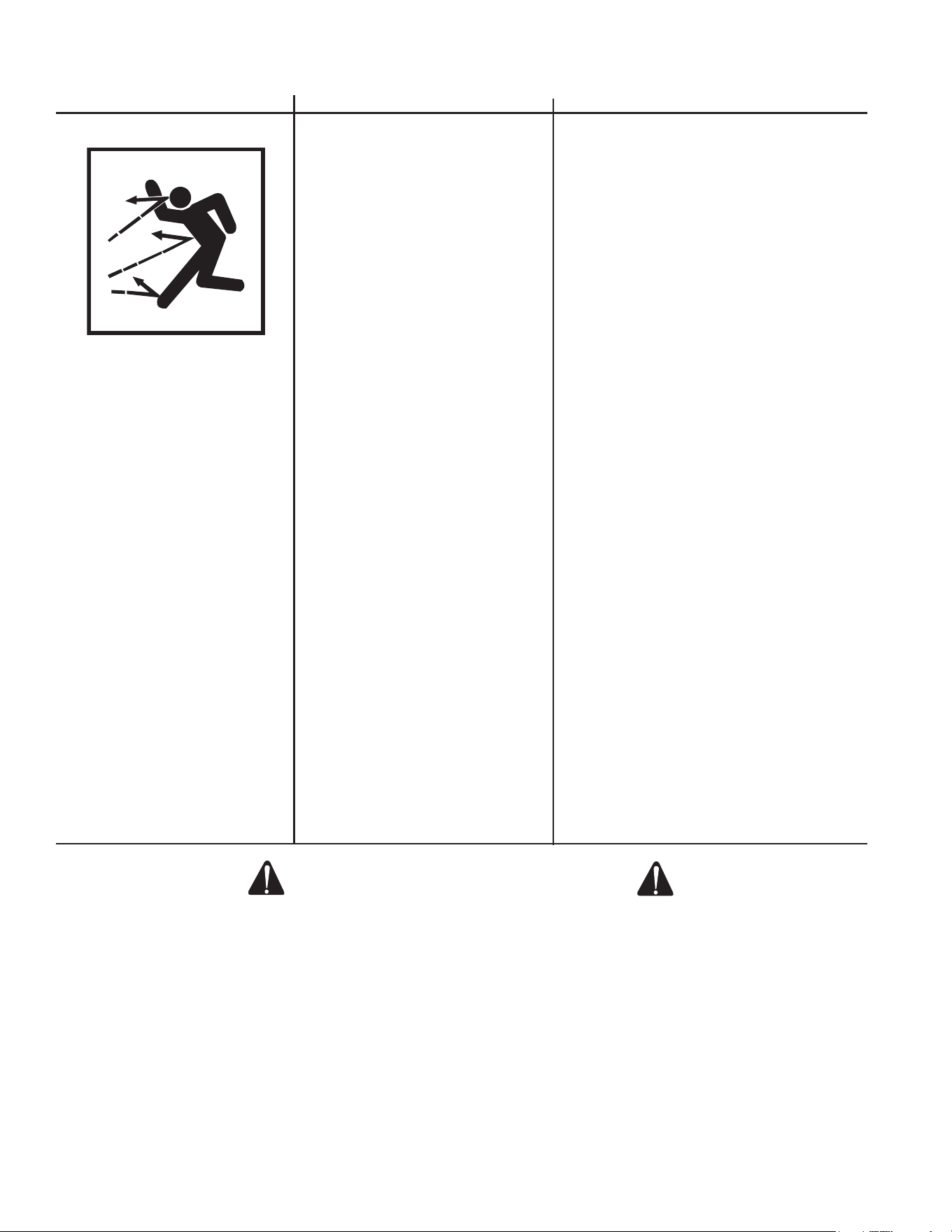
42 Manual del operador
!SALVE ESTAS INSTRUCCIONES!
RIESGO DE LESIONES
ADVERTENCIAS DE SEGURIDAD
Lea todas Las advertencias de seguridad antes de usar la lavadora a presión.
SIEMPRE sostenga rmemente el conjunto de
pistola/varilla cuando arranque y opere la uni-
dad. No hacerlo podría provocar que la varilla
se caiga y se azote peligrosamente.
Sepa como detener la lavadora a presión y
aliviar las presiones rápidamente. Familiarícese
por completo con estos controles.
Siga todas las instrucciones de mantenimiento
que especicós en la manual.
NO permita que la unidad presurizada per-
manezca sola. Apague la lavadora de presión y
libere la presión antes de irse.
NO OPERE la unidad si detecta fugas de
combustible, aceite o agua de la máquina. NO
reanude la operación hasta que la unidad haya
sido inspeccionada y reparada por un técnico
capacitado para el servicio.
NUNCA accione la unidad con el regulador
desconectado ni opere a velocidades excesi-
vas.
Coloque la unidad sobre una supercie limpia,
seca y plana para darle servicio. Antes de dar
mantenimiento a la unidad, apáguela, alivie la
presión de agua apretando el gatillo de la pis-
tola, y permita que la unidad se enfríe. Realice
el mantenimiento en un área limpia, seca y
plana. Donde sea necesario, bloquee las ruedas
para prevenir el movimiento de la unidad.
No tire de la manguera para mover la unidad.
Pueden ocurrir lesiones provocadas por
la lavadora a presión.
PELIGRO
POSIBLE CONSECUENCIA
PREVENCIÓN
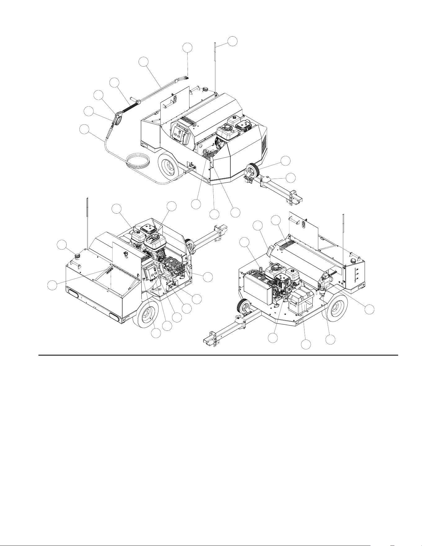
Manual del operador 43
HMT-4004-0MGH CARACTERÍSTICAS
20
16
15
17
18
19
21
22
14
12
11
13
1
6
8
9
10
2
3
7
4
5
25
23
27
26
28
29
24
1. Poseedor de boquilla de conexión rápido
2. Tanque de comestible- Verde / 10 galón
3. Motor
4. Tanque de gas- rojo / 10 galón
5. Estárter
6. Panel de control
7. Interruptor
8. Entrada de agua
9. Salida de agua
10. Bomba de presión alta
11. Gancho de la pistola
12. Asamblea de armazón
13. Interruptor de presión
14. Manguera de presión alta
15. Cerradura de seguridad de gatillo
16. Gatillo de pistola
17. Lanza aislamientado
18. Doble- Lanza de presión ajustable
19. Boquilla de presión alta
20. Bandera De Seguridad
21. Ensamblaje De Ruedas
22. Acoplador Oscilante
23. Valvula de descarga caliente/ Valvula de descargar
24. Interruptor De Llave
25. Salida de intercambiadora de calor
26. Ajustado de quemador del aire
27. Filtro de comestible / separador de agua
28. Caja de batería
29. Sumidero del aceite de motor

44 Manual del operador
INSTALACIÓN Y PREPARACIÓN
SEGURIDAD:
ADVERTENCIA: NO OPERE ESTE REMOLQUE HASTA QUE HAYA LEÍDO Y COMPRENDIDO ESTE MANUAL.
1. Lea y entienda minuciosamente todas las instrucciones antes de utilizar este remolque.
INFORMACIÓN SOBRE DEFECTOS DE SEGURIDAD:
Si usted cree que su vehículo tiene un defecto que podría causar un accidente o causar lesiones o muerte, debe
informar inmediatamente a la Administración Nacional de Seguridad del Tráco de Carreteras (NHTSA por sus siglas
en inglés) además de noticar al fabricante del remolque.
Si NHTSA recibe denuncias similares, puede iniciar una investigación y, si se determina que existe algún defecto de
seguridad en un grupo de vehículos, se puede ordenar una campaña de recuperación y reparación. Sin embargo,
NHTSA no puede involucrarse en problemas individuales entre usted y su distribuidor local.
Para comunicarse con NHTSA, puede llamar al número gratuito de Línea Directa De Seguridad Automática al 1-800-
424-9393 (o al 366-0123 en el área de Washington, DC) o escribir a NHTSA, Departamento De Transporte De Los
Estados Unidos, Washington, DC 20590. También puede obtener información sobre la seguridad de los vehículos de
motor en línea directa.
ANTES DE ACARREAR EL REMOLQUE:
ADVERTENCIA: ANTES DE UTILIZAR UN VEHICULO DE ACARREO CON UN REMOLQUE, VERIFIQUE
QUE EL VEHICULO HAYA SIDO DESIGNADO PARA LA CARGA. UTILIZAR UN VEHICULO DEMASIADO
PEQUENO ES MUY PELIGROSO. ASEGURESE DE QUE PUEDA MANEJAR EL M.G.T.W. (PESO MAXIMO
DEL REMOLQUE POR SU SIGLAS EN INGLES) Y EL PESO DE LA LENGÜETA PARA ACARREOS Y
FRENOS SEGUROS.
SELECCIÓN DEL EQUIPO DE REMOLQUE ADECUADO
PESO
Al seleccionar el equipo de remolque adecuado, los dos factores más importantes que deben ser considerados son
el M.G.T.W. (Peso Bruto Máximo Del Remolque) y el Peso De La Lengüeta. El M.G.T.W. es el peso total del remolque
más la carga útil del remolque. El peso de la lengüeta es la presión descendente ejercida en el acoplador. La forma
más sencilla de medir el peso bruto del remolque es colocando el remolque cargado en una báscula o balanza para
vehículos, asegurándose de que la misma soporte todo el peso del remolque cargado.
El método más sencillo para medir el peso de la lengüeta (hasta 300 libras) es colocar el soporte del gato (lengüeta
del remolque) en una báscula o balanza casera asegurándose de que el remolque esté nivelado. Para lengüetas de
mayor peso, coloque una tabla sobre la balanza casera y un objeto sólido del mismo grosor a la balanza con un ped-
azo de cañería entre uno y el otro. La lengüeta del remolque debe estar nivelada y en su posición de remolque normal.
Multiplique la lectura de la balanza por tres (3) para obtener el peso de la lengüeta. Asegúrese de que el vehículo de
remolque pueda remolcar la carga.
• Asegúrese de que la capacidad de enganche sea igual o superior a la carga cuando esté montada en el vehí-
culo.
• Asegúrese de que el tamaño y la clasicación de la bola de enganche sean iguales o superiores a la carga.
• Asegúrese de que el valor nominal de las cadenas de seguridad sea igual o superior al doble del peso bruto
máximo del remolque.
• Es contrario a la ley llevar pasajeros en la parte trasera de cualquier remolque.
• Cualquier modicación o cambio realizado en el remolque anula cualquier garantía expresa o implícita sobre el
remolque o el equipo de remolque.
• Compruebe que las tuercas estén bien apretadas antes del viaje inicial, a 25 millas, y cada 100 millas de oper-
ación a partir de entonces.
VEHÍCULO DE REMOLQUE
Asegúrese de que el vehículo que utiliza para acarrear el remolque es capaz de acarrear el peso. Consulte el Manual
De Propietario del vehículo para comprobar la capacidad de remolque del vehículo o póngase en contacto con el dis-
tribuidor de su automóvil para obtener información. Asegúrese de que el remolque del vehículo sea capaz de acarrear
la carga. La capacidad de freno del vehículo es crítica y el vehículo de remolque debe ser capaz de manejar el peso
adicional del remolque. El radiador y la refrigeración del sistema de transmisión también deben ser considerados.
CAPACIDAD DE ENGANCHE DEL REMOLQUE
Clase De Enganche Capacidad Máxima De Remolque Peso Máximo de Lengüeta
Subclase I 1000 Libras. 100 Libras.
Clase I 2000 Libras. 200 Libras.
Clase II 3500 Libras. 300 Libras.
Clases III y 4 5000 Libras. extra 500 Libras. extra

Manual del operador 45
CADENAS DE SEGURIDAD
En la siguiente tabla se enumeran las diferentes clases de cadenas de seguridad y carga nominal que debe soportar
cada cadena.
ADVERTENCIA: LA NO FIJACIÓN ADECUADA DE CADENAS DE SEGURIDAD ENTRE EL REMOLQUE Y EL
VEHÍCULO DE REMOLQUE PUEDE PRODUCIR UNA FUGA DEL MISMO.
ADVERTENCIA: PARA EVITAR ACCIDENTES, ANTES DE REMOLCAR:
• Enganche sólo al tamaño de la bola marcado en el acoplador.
• La abrazadera de la bola debe capturar la bola y la palanca o el volante está totalmente sujetado
• Cruce las cadenas de seguridad debajo el acoplador.
• Déjelo lo sucientemente ojo como para permitir giros.
CABLEADO ELECTRICO DEL REMOLQUE
Todos los remolques deben tener luces traseras, luces de freno y de giro conectadas al sistema eléctrico del ve-
hículo de remolque. También se recomienda instalar una señal intermitente de giro de alta resistencia y una señal
intermitente de emergencia (si están separadas) ya que las luces del remolque colocan una carga adicional en las
unidades intermitentes del vehículo.
ACARREO DE CARGAS PESADAS DE REMOLQUE
Equipamiento adicional. Los siguientes artículos pueden ser útiles para remolcar cargas pesadas. Consulte el
Manual De Propietario de su vehículo o concesionario para recomendaciones de accesorios de remolque.
• Resortes para sobrecarga
• Amortiguadores de aire o sobrecarga
• Aceite Para Refrigeración de Transmisión
• Refrigerador De Aceite De Motor
• Sistema De Refrigerante de Recuperación
• Ventilador Para Servicios Pesados
• Espejos Laterales
• Control De Balanceo
PRESION DE LOS NEUMATICOS
La presión de aire apropiada para sus neumáticos se encuentra impresa en las paredes exteriores de los mismos.
Compruebe la presión de los neumáticos mientras están fríos. No suba ni baje dicha presión para cumplir con el
peso de carga. Presión diferente a la recomendada provocará un desgaste excesivo o falla en los neumáticos.
Balanceo recomendado. El método de balanceo preferido es centrar los oricios de los pernos, ya que las ruedas
de 13" a 16.5" no están centradas.
ADVERTENCIA: EN UN REMOLQUE NUEVO, LAS TUERCAS DE LAS RUEDAS DEBEN SER APRETADAS
A LA ESPECIFICACIÓN DE TORSIÓN ADECUADA ANTES DEL USO, A 25 MILLAS DE OPERACIÓN Y
CADA 100 MILLAS DE OPERACIÓN A PARTIR DE ENTONCES. SI NO SE COMPRUEBA EL CORRECTO
APRIETE DE LAS TUERCAS, ESTO PUEDE RESULTAR EN UN ACCIDENTE DEBIDO A LA CAÍDA DE
UNA RUEDA DEL REMOLQUE.
ADVERTENCIA: NUNCA OPERE UN REMOLQUE O VEHÍCULO DE REMOLQUE QUE TENGA UNA TUERCA
SUELTA, FALTANTE O ROTA. EL REMOLQUE ESTÁ DISEÑADO PARA UNA SEGURA OPERACIÓN
TENIENDO TODAS LAS TUERCAS APROPIADAMENTE INSTALADAS Y CON LA TORSIÓN
APROPIADA. LA OPERACIÓN DEL REMOLQUE CON UNO O MÁS TUERCAS ROTAS O FALTANTES
AUMENTA EN GRAN MEDIDA LA CARGA SOBRE LAS TUERCAS RESTANTES Y PUEDE CAUSAR LA
FALLA DE LAS MISMAS, LO CUAL PUEDE RESULTAR EN UN ACCIDENTE DEBIDO A LA CAÍDA DE
UNA RUEDA DEL REMOLQUE.
INSTALACIÓN Y PREPARACIÓN
Clase del Remolque Peso del remolque en libras. Fuerza de freno mínima en libras.
Clase I hasta 2000 Libras 2000 Libras
Clase II De 2000 a 3500 Libras 3500 Libras
Clase III De 3500 a 5000 Libras 5000 Libras
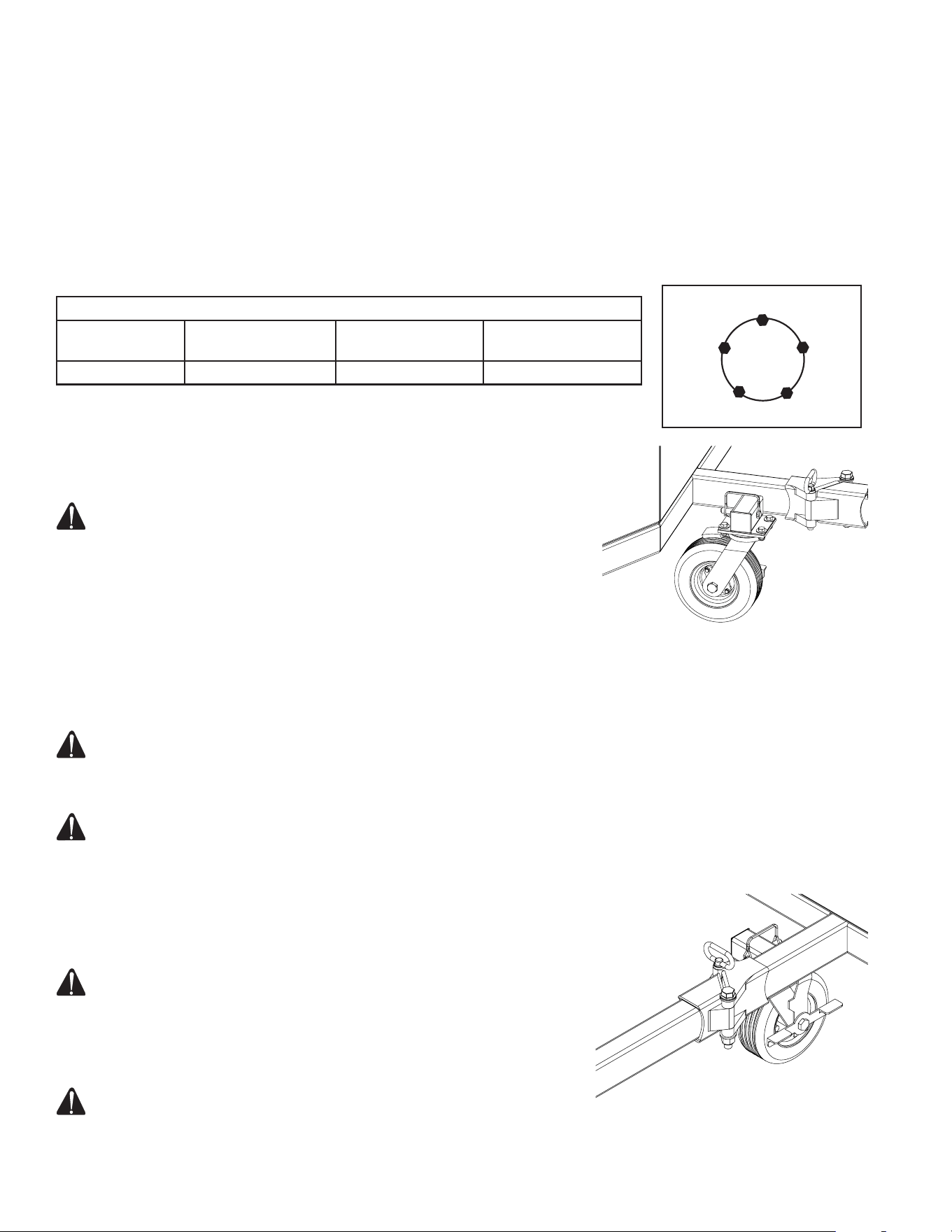
46 Manual del operador
TUERCAS DE LAS RUEDAS
Las tuercas de las ruedas deben ser apretadas con una llave dinamométrica. Consulte la tabla que aparece a con-
tinuación para conocer el par de torsión adecuado.
1. Comience apretando todas las tuercas a mano para prevenir que se enrosquen de mala manera.
2. Apriete las tuercas hacia la derecha.
3. El apriete de las tuercas debe hacerse por etapas. Siguiendo la secuencia recomendada, apriete las tuercas según
la tabla de torsión de rueda que se muestra a continuación.
4. Las tuercas y tornillos de las ruedas deben ser apretadas antes de ser usadas por primera vez en la carretera y
después de que las ruedas sean quitadas. Revise y vuelva a apretar después de las primeras 10 millas, 25 millas
y otra vez en 50 millas.. Chequéelo periódicamente, a partir de entonces.
OPERACIÓN DE RUEDECILLAS
Este remolque está equipado con una ruedecilla montada en la lengüeta para
su uso cuando no está acoplado al vehículo de remolque.
ADVERTENCIA: LA RUEDECILLA DEBE ESTAR EN POSICIÓN
VERTICAL CUANDO ESTE CONECTADA AL VEHÍCULO DE
REMOLQUE PARA QUE EL REMOLQUE SEA SEGURO Y
ADECUADO.
Para colocar la ruedecilla en posición vertical, retire el pasador de seguridad
y saque la ruedecilla del remolque. Gire el soporte de la ruedecilla 90 grados
e instálela en el remolque. Instale el pasador de seguridad y cerciórese de
que el cable de bloqueo esté asegurado.
OPERACION DE FRENOS
Este remolque está equipado con un mecanismo de freno montado sobre ruedecillas que se utiliza cuando no está
acoplado al vehículo de remolque.
ADVERTENCIA: PARA EVITAR LESIONES, SE DEBE APLICAR EL FRENO DEL REMOLQUE CUANDO LA
UNIDAD SE ENCUENTRE EN OPERACIÓN Y CUANDO NO ESTE EN USO.
Para activar el freno de ruedecilla, simplemente pulse la palanca de freno con el pie. Para desbloquear el freno, tire
de la palanca de freno hacia arriba hasta que esté en posición horizontal.
ATENCION: EL COLOCAR LA PALANCA DE FRENO POR ENCIMA DE LA POSICIÓN HORIZONTAL NO
PERMITIRÁ QUE LA RUEDECILLA GIRE Y PUEDE CAUSAR DAÑOS EN LA PINTURA.
OPERACIÓN DE LA LENGÜETA OSCILANTE
Este remolque está equipado con un kit de acoplamiento de lengüeta osci-
lante para un almacenamiento compacto.
ADVERTENCIA: EL PERNO DE LA BISAGRA DEBE SER INSTALADO
Y ASEGURADO DE MANERA OSCILANTE CUANDO SE
LO ENGANCHA AL VEHÍCULO DE REMOLQUE PARA UN
REMOLQUE SEGURO Y ADECUADO.
Para operar el acoplador oscilante, quite la clavija de la bisagra. Remueva la
bisagra del acoplador y gire la lengüeta hacia un lado.
ATENCION: INSTALAR EL PERNO DE LA BISAGRA EN EL LADO
FIJO DE LA OSCILACIÓN CUANDO ESTA SE USE PARA EVITAR PÉRDIDAS Y DAÑOS.
INSTALACIÓN Y PREPARACIÓN
Secuencia de Torsión
Tamaño de
rueda
1ra Etapa 2da Etapa 3ra Etapa
16" 20-25 50-60 80-90
1
2
34
5
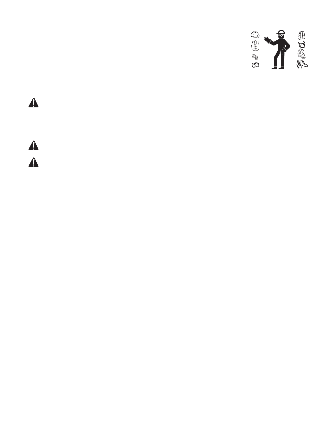
Manual del operador 47
PREPARACIÓN INICIAL:
1. Este aparato debe quedar siempre colocado sobre una supercie nivelada para asegurar la lubricación apropiada
del motor y de la bomba de agua durante la operación. NUNCA rocíe agua directamente a la unidad.
ADVERTENCIA: ¡PELIGRO RIESGO DE EXPLOSIÓN O INCENDIO! -CUANDO SE CARGAN BATERÍAS,
ÉSTAS GENERAN UN GAS DE HIDRÓGENO ALTAMENTE EXPLOSIVO. ¡UNA CHISPA PODRÍA
CAUSAR UNA EXPLOSIÓN O UN INCENDIO!-NO ARRANQUE LA BATERÍA CON FUENTE DE ENERGÍA
AUXILIAR A MENOS DE QUE AMBAS BATERÍAS SEAN DE VOLTAJE O AMPERAJE EQUIVALENTES.-
NO FUME NI PERMITA QUE HAYA CHISPAS O LLAMAS CERCA DE LA BATERÍA.-NO COLOQUE LA
UNIDAD EN UNA ÁREA DONDE PUEDAN EXISTIR VAPORES INFLAMABLES. UNA CHISPA PODRÍA
PROVOCAR UNA EXPLOSIÓN O UN INCENDIO.
ADVERTENCIA: ¡RIESGO DE LA EXPLOSIÓN DE LA UNIDAD! ¡NO ALMACENE/OPERE LA UNIDAD EN
AMBIENTES DE CONGELACIÓN!
ADVERTENCIA: ¡RIESGO DE ASFIXIA! ¡USE ESTE PRODUCTO ÚNICAMENTE EN ÁREAS BIEN
VENTILADAS! NO OPERE EN UNA ÁREA ENCERRADA. EL ESCAPE EXPULSA MONÓXIDO DE
CARBONO, UN GAS VENENOSO INODORO E INVISIBLE. RESPIRAR ESTE GAS PUEDE PROVOCAR
LESIONES GRAVES, ENFERMEDAD O POSIBLE MUERTE.
2. No use esta unidad en un área:
a. sin suciente ventilación
b. donde haya evidencia de fugas de aceite, gas o combustible.
c. donde pueda haber presencia de vapores inamables.
Esta unidad tiene varias fuentes de ignición que podrían provocar una explosión o incendio.
3. No permita que la unidad quede expuesta temperaturas de congelación. Si alguna parte de la unidad se congela, es
posible que se acumule una presión excesiva en la unidad, lo cual podría provocar su estallido y consecuentemente
posibles lesiones al operador o las personas alrededor.
4. El nivel de aceite de la bomba debe ser chequeado antes de cada uso. Compruebe el nivel de aceite en la mirilla
de nivel de la parte trasera de la bomba. El nivel de aceite debe estar por la mitad de la mirilla. Si el nivel parece
estar bajo, llénelo con aceite sin detergente de bomba de 10-40W. El nivel de aceite también puede comprobarse
usando una varilla en la parte superior de la bomba.
5. Especicaciones De la Batería:
- RV / Marine cylce profundo del propósito dual y batería que cigüeñal.
- BCI grupo 24DC.
- Tamaño de la caja de la batería: 27.9cm x 19.05cm x 20.9cm (la batería puede ser ligeramente más alta y
todavía cubrir por la tapa.
- La batería debe tener correa de elevación para la instalación fácil.
VESTIMENTA:
Es importante usar ropa apropiada para su seguridad. Se aconseja usar cualquier medio
necesario para proteger los ojos, las orejas y la piel. Posiblemente requiera equipo adi-
cional de seguridad (como un respirador) cuando use detergentes limpiadores con esta
lavadora.
INSTALACIÓN Y PREPARACIÓN
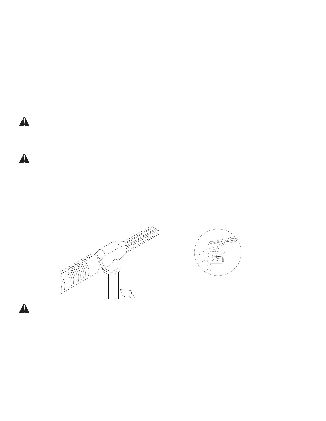
48 Manual del operador
TANQUES DE COMBUSTIBLE DEL MOTOR/QUEMADOR:
1. Lea las advertencias de “Riesgo de explosión o incendio”, página 64, antes de llenar con combustible.
2. Localice las calcomanías de seguridad en su unidad y preste atención a sus advertencias.
3. Motores de gasolina: Vea el manual del motor para necesidades de gasolina.
Combustible del quemador: Cuando llene el tanque (negro), use aceite de combustible No.1 o No.2/ diesel o
queroseno.
4. Revise el nivel de aceite del motor antes de arrancarlo. (Vea el manual del motor).
5. Vea el manual del motor que se ha proporcionado con esta unidad, para familiarizarse con los procedimientos
apropiados de ajuste.
6. Repase el manual del motor que acompaña a esta lavadora a presión para familiarizarse con los procedimientos
correctos de arranque y mantenimiento.
ADVERTENCIA: PELIGRO ¡RIESGO DE INCENDIO! ¡NO FUME MIENTRAS ESTÉ CARGANDO
COMBUSTIBLE! NO LLENE LOS TANQUES DE COMBUSTIBLE MIENTRAS LA MÁQUINA ESTÉ
EN FUNCIONAMIENTO O ESTÉ CALIENTE. PERMITA QUE LA MÁQUINA SE ENFRÍE POR DOS
MINUTOS ANTES DE VOLVER A CARGAR COMBUSTIBLE. NO LLENE DEMASIADO LOS TANQUES DE
COMBUSTIBLE PORQUE SE PUEDEN DERRAMAR. DEBE QUEDAR UN ESPACIO LIBRE DE 1/4” (6,5
MM) EN EL TANQUE PARA PERMITIR LA EXPANSIÓN DEL COMBUSTIBLE.
ADVERTENCIA: ¡RIESGO DE EXPLOSIÓN O INCENDIO! SIEMPRE ALMACENE EL COMBUSTIBLE LEJOS
DE LA LAVADORA MIENTRAS LA UNIDAD ESTÉ EN FUNCIONAMIENTO O SE ENCUENTRE CALIENTE
CONJUNTO DE VARILLA DOBLE CON PRESIÓN AJUSTABLE:
Esta unidad tiene un conjunto de varilla doble con presión ajustable que permite al usuario seleccionar el rocío en
abanico a baja o alta presión. Simplemente gire el mango ajustable de la varilla doble para seleccionar la presión
deseada.
1. Se puede seleccionar la presión alta girando el mango ajustable en el conjunto de varilla doble en sentido antihorario
como se muestra en la gura siguiente.
2. Se puede seleccionar la aplicación de detergente a baja presión girando el mango ajustable de la varilla doble en
sentido horario como se muestra en la gura de abajo.
ADVERTENCIA: ¡RIESGO DE INYECCIÓN QUE PUEDE CAUSAR UNA LESIÓN GRAVE! LA PISTOLA
DE GATILLO SIEMPRE DEBE ESTAR TRABADA EN SU POSICIÓN CERRADA CUANDO NO SE
USE!¡NUNCA VEA DIRECTAMENTE HACIA LA BOQUILLA A MENOS QUE ESTÉ DESCONECTADA DEL
CONJUNTO DE PISTOLA Y VARILLA DOBLE!
INSTALACIÓN Y PREPARACIÓN
PRESIÓN ALTA
HACIA LA IZQ.
PRESIÓN BAJA
HACIA LA DER.
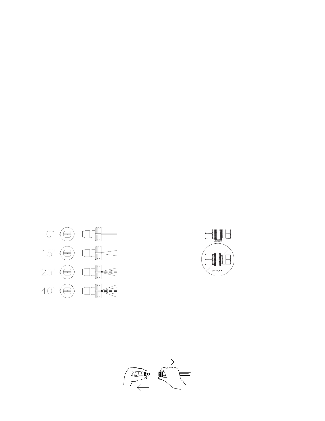
Manual del operador 49
INSTALACIÓN Y PREPARACIÓN
BOQUILLAS
CERRADUAR DE BOQUILLA
BOQUILLAS DE CONECTORES ROSCADOS:
Boquillas varias se puede estar conectores roscados en el n de doble lanza para combiar el diseno de atomizadora.
La boquilla de detergente ha preintalado en la fabrica. Cuando usando conexiónes roscados (Q.C) asegúrese de que
la conexión tiene cerradura seguras como el foto a la derecha. Si no está segura la presión alta se puede salir dis-
parado la boquilla de la lanza. Este se puede ocurrir lesiones graves o danos serios. Referir al número que imprimió
en la boquilla para determinar ventilador de atomizadora. Los dos dígitos primeros indicar el grado de ventilador de
atomizador:
1. La boquilla de 0° (Rojo):
Esta es una boquilla de explosión. Repartir un corriente muy concentrado de agua. Ten ciudado cuando usando
el corriente recto. No es recomendado para usar en supercies de maderna o con pinta o cosas con repaldos con
adhesivo. USAS: Eliminación de hierbas de grietas de aceras, manchas fuertes de concreto, manpostería, aluminio
y acero, barro del equipo, y para limpiar partes inferiores de máquinas de cortar el césped.
2. La boquilla de 15° (Amarillo):
Esta es una boquilla de cincelar. La atomizadora se pone en un angle de 45° del supercie y usar como una rajadadora
para elimintar pinta, grasa, y mugre. USAS: Preparación de supercie (eliminación de manchas de mildeu y astillas
de pinta).
3. La boquilla de 40° (Blanco):
Esta boquilla es una boquilla de limpiando. Este diseno extenso de atomizadora dispatir la presión de agua alrededor
un área grande y se recomendado para limpiando moderado. USAS: Limpiando de apartadero de aluminio, limpiando
ventanillas, limpiando autos, atomizadando aceras, entradas de casas, y patios.
4. La boquilla de 25° (Verde):
Esta es una boquilla limpiando. Este diseño es mejor para limpiando de suciedad, barro, y mugre. Usas: Barrido
de hojas mojadas de aceras, bordillos, entradas para coches, limpiando de pisos en caballerizas, lavando pisos
de piscinas, dengrasando de motores.
5. La boquilla de 65° (Se includido con doble lanza):
Esta boquilla es de detergente. El diseno extenso de atomizador dar solución alrededor áreas grandes. USAS:
Aplicación, empanando, o enjuagando de detergente.
CONEXIÓN DE BOQUILLA:
1. Asegúrese de que gatillo de pistola está cerradura en posición de OFF.
2. Boquillas de conectores roscados se puede conectar o desconectar de assemblea de doble lanza por retractarse
los anillos de cerradura en instalaciónes de contector roscado. Cuando conectando la boquilla deseable, empuje
el anillo de cerradura por encima de conector roscado de boquilla para dar seguridad de conexión.
CONEXIÓN DE BOQUILLA
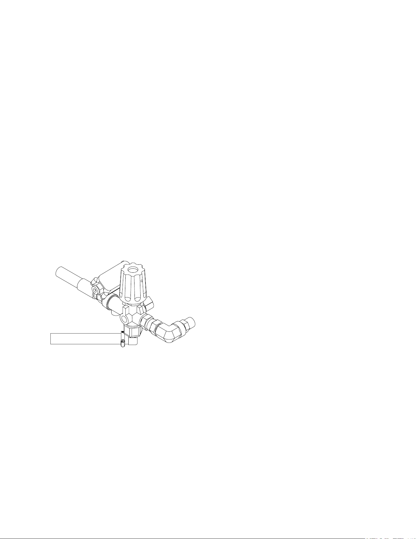
50 Manual del operador
SUMINISTRO DE AGUA:
SUMINISTRO PRESURIZADO:
1. Seleccione una manguera de suministro de agua de jardín de buena calidad que tenga por los menos 3/4" (19 mm)
de diámetro interno y no sea mayor de 50 pies (15,25 m).
2. Asegúrese de que la malla de agua es limpiado y libre de obstruciónes. Si el ujo del agua se queda restringido a
la bomba, vacilacion puede ocurrir. Este podria causar falla prematura de la bomba.
3. Si conectar uno del n de mangurera de suministro de agua a entrada y conectar el otro n a suministro presurizado
de agua.
NOTA: Si existe un alto grado de contenido mineral en su agua, se recomienda usar un ablandador de agua para
prevenir la posibilidad de una acumulación excesiva de incrustaciones dentro del serpentín del intercambia-
dor de calor.
4. Use la necesidades de aga entrada como tener abajo:
a. Presión del agua necesitar estar entre de un mínimo de 40 PSI y máxima de 65 PSI.
b. La entrada de GPM tiene que estar un galón más de cada minúto de la salida de GPM que indicado en plato
de nombre de la maquina. (Puede controlar el GPM de su fuente como encendido de relleno de un envase de
cinco galones.)
c. La temperatura del agua entrada no exceder de 125°F. Dano grande de bomba se resulto si la temperatura del
agua excedor este nivel.
5. Nunca permita que la unidad opere sin que la línea de agua de entrada esté conectada y sin que el suministro de
agua esté completamente abierto.
DESCARGA:
La descarag ha preprogramado en la fábrica.
PROCEDIMIENTOS DE INSPECCIÓN ANTES DEL ENCENDIDO:
Antes de encender la unidad, realice los siguientes procedimientos:
1. Revise el nivel de aceite de la bomba.
2. Revise la malla ltrante de la entrada de agua. Limpie o reemplace de ser necesario. Vea “Suministro de agua”.
3. Revise todas las conexiones de la manguera para asegurarse de que estén bien ajustadas. Vea “Suministro de
agua”.
4. Inspeccione para asegurarse que no existan fugas de agua, aceite o combustible del sistema. Si encuentra una fuga
de combustible, ¡NO ENCIENDA LA UNIDAD!0 Vea la sección de advertencias de “Riesgo de explosión o incendio”.
Asegúrese que se hayan reemplazado todas las partes dañadas y se hayan corregido los problemas mecánicos,
antes operar de nuevo la unidad. Si requiere servicio, llame a la ocina de Servicio a clientes.
5. Inspeccione las mangueras de alta presión para asegurarse que no tengan dobleces, rupturas o fugas. Si se
encuentra una ruptura o fuga, ¡NO USE LA MANGUERA! Reemplace la manguera antes de encender la unidad.
Vea “Riesgo de inyección”. Asegúrese que se hayan reemplazado todas las partes dañadas y se hayan corregido
los problemas mecánicos, antes operar de nuevo la unidad. Si requiere servicio, llame a la ocina de Servicio a
clientes.
INSTALACIÓN Y PREPARACIÓN
AQUÍ TERMINAN LAS INSTRUCCIONES DE PREPARACIÓN

Manual del operador 51
ADVERTENCIA
LAS SIGUIENTES PÁGINAS CONTIENEN INSTRUCCIONES SOBRE LA OPERACIÓN Y EL
MANTENIMIENTO.
NO INTENTE OPERAR ESTA LAVADORA A PRESIÓN O TU REMOLQUE HASTA QUE HAYA LEÍDO Y
COMPRENDIDO TODAS LAS PRECAUCIONES E INSTRUCCIONES DE SEGURIDAD SEÑALADAS EN
ESTE MANUAL.
¡LA OPERACIÓN INCORRECTA DE ESTA UNIDAD PUEDE CAUSAR LESIONES GRAVES!
¡NO ALTERE NI MODIFIQUE ESTE EQUIPO DE NINGUNAMANERA!

52 Manual del operador
CUANDO ACCAREA EL REMOLQUE:
ADVERTENCIA: NUNCA PERMITA QUE UNA PERSONA VIAJE EN UN REMOLQUE QUE ESTÁ
SIENDO REMOLCADO. TODOS LOS ESTADOS PROHIBEN PASAJEROS EN VEHÍCULOS SIENDO
REMOLCADOS. ULGUNA PERSONA PUEDE CAER Y SER GOLPEADA POR OTRO VEHÍCULO O
ATRPELLADA POR EL MISMO REMOLQUE. EL INCUMPLIMIENTO DE ESTA ADVERTENCIA PUEDE
OCASIONAR LA MUERTE.
PRECAUCIONES DE SEGURIDAD DURANTE EL USO
Carga del remolque. El remolque debe ser cargado de manera que el peso descendente de la lengüeta sea aproxi-
madamente el 10% del peso bruto del remolque. Engánchelo sólo a los puntos de enganche recomendados por el
fabricante del vehículo del remolque.
Distancia de seguimiento y de parada. La distancia de parada aumenta cuando se transporta un remolque. Una
regla general para la distancia mínima que debe mantenerse entre usted y el automóvil precedente sobre pavimento
seco es la longitud de un automóvil y un remolque (2 automóviles) por cada 10 MPH de viaje. La distancia debe au-
mentarse de acuerdo con las condiciones de la carretera y el clima. Evite las paradas bruscas si es posible. Maneje
el vehículo remolcador con cuidado, sin giros, arranques o paradas bruscas. Cuando sea posible, evite manejar el
vehículo remolcador cerca de zanjas, terraplenes y agujeros y reduzca la velocidad cuando atraviese terrenos irregu-
lares o desnivelados.
Pasar. La aceleración y el pasar deben hacerse lentamente para permitir una distancia extra al pasar. Señale con
mucha anticipación cuando vaya a pasar y vuelva al carril apropiado. Tenga en cuenta la longitud extra del remolque
antes de cambiar de carril. Nunca cambie de carril de manera abrupta ya que esto puede causar que el remolque se
balancee y empuje el vehículo remolcador a una posición "navaja".
Giros. Tenga en cuenta la longitud extra del remolque. Conduzca un poco más allá del punto de giro normal para
evitar chocar con los cordones de la acera. El radio de giro aumenta con el uso del remolque. Reduzca la velocidad
al girar, al cruzar pendientes y en supercies irregulares, resbaladizas o embarradas.
Grados de Ascenso y Descenso. Reduzca la velocidad y use un engranaje de transmisión más bajo para pendien-
tes empinadas o largas en subida o en bajada. Mantenga una distancia segura con los demás vehículos.
Aparcamiento. Cuando el vehículo de remolque esté inactivo, aplique los frenos y estacione con seguridad.
• Evite estacionar cuesta arriba o cuesta abajo.
• Ponga la transmisión en "PARK" (parqueo).
• Ponga el freno de mano.
• Usar cuñas para las ruedas.
• En el estacionamiento, evite estacionar cerca de otros vehículos. El radio de giro es mayor y puede ser imposible
salir de una plaza de aparcamiento después de que otros vehículos hayan aparcado alrededor de su vehículo.
ASIEMPRE APAGUE EL MOTOR DEL VEHÍCULO DE REMOLQUE ANTES DE HACER AJUSTES O
REPARACIONES A UN REMOLQUE MONTADO.
DESPUES DE SU USO:
1. Inspeccione el remolque para determinar si está desgastado o dañado.
2. Asegúrese de que todos los tornillos y conexiones estén bien apretados.
3. Verique que las señales de freno, traseras y de giro funcionen correctamente.
4. Compruebe que los cables estén bien conectados y que no estén deshilachados o desgastados.
5. Revise y mantenga apropiadamente el remolque, enganche, gato, bola y acoplador.
6. Inspeccione enganche y bola para ver si hay daños. La bola o el enganche pueden dañarse al estacionar, al golpear
contra los cordones de la acera, al ser arrastrados al cruzar zanjas y/o vías de ferrocarril.
7. Revise y apriete correctamente todos los pernos del remolque, enganche, bola y acoplador (incluyendo las ruedas).
8. Compruebe que las cadenas de seguridad no estén desgastadas y no permita que estas se arrastren por el suelo
o carretera.
9. Revise las llantas del vehículo remolcador para ver si están desgastadas y tienen la presión adecuada (revise el
manual del propietario del vehículo para vericar el nivel de presión adecuado de las llantas para remolcar un
remolque).
10. Revise las llantas del remolque para ver si están desgastadas y tienen la presión adecuada. Reemplace solamente
con una llanta del mismo tamaño y capacidad.
11. Para mantenimiento apropiado del vehículo remolcador, mientras lo remolca, revise el manual del propietario del
vehículo y las especicaciones del fabricante.
INSTRUCCIONES DE OPERACIÓN
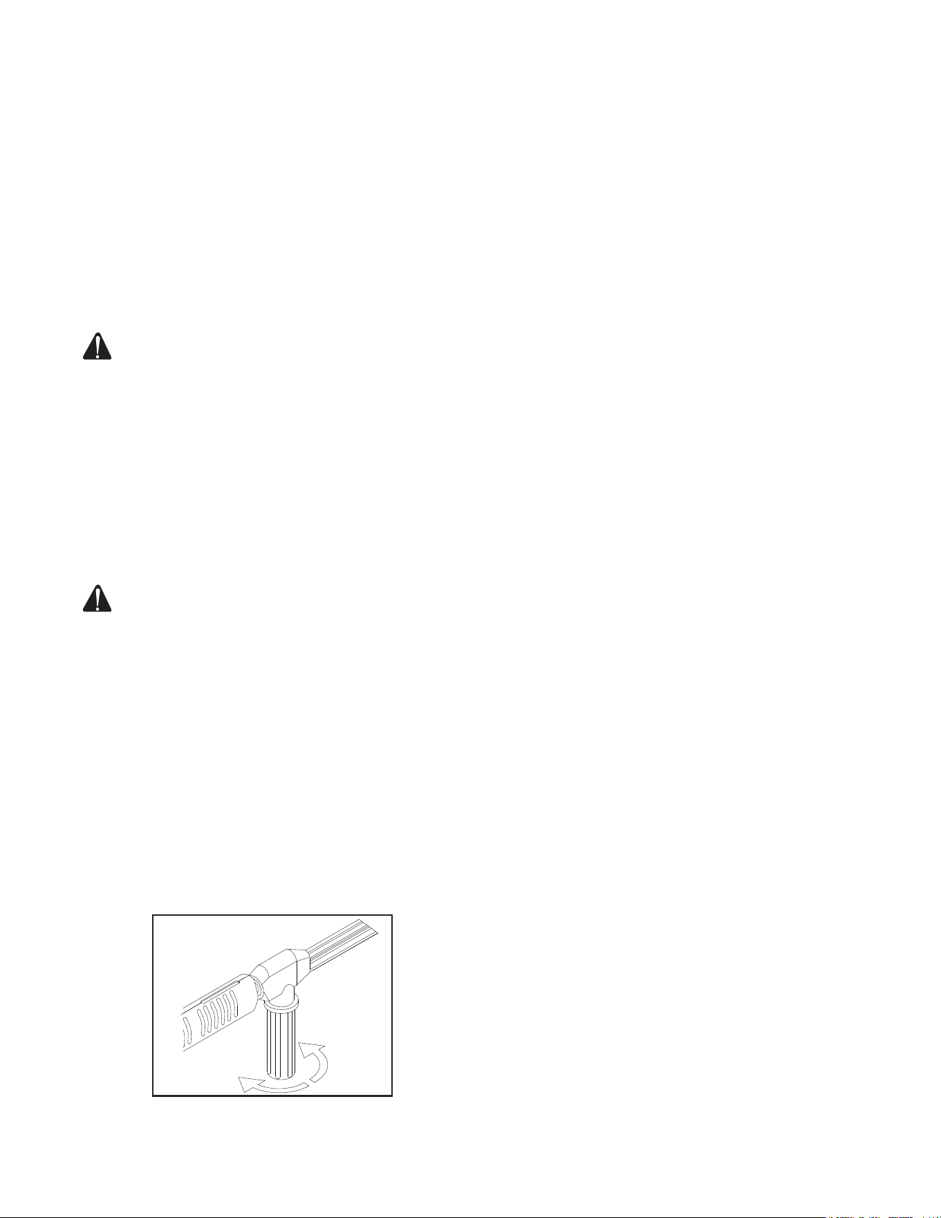
Manual del operador 53
FUNCIONANDO EL SISTEMA:
Esta unidad tiene un rollo de acero que despues de colocando, causará los resto del agua en el rollo de usos ante-
riores cambiar a marrón o negro. Este agua tiene que funcionar del sistema antes de encender. Este procedimiento
debe desempeñar sin la instalación de manguera de presión alta, pistola y asamblea de lanza.
1. Encender el suministro del agua.
2. Enceder el motor de unidad. Agua de presión baja empezará uir de la salida de agua. Este permitir la unidad para
funcionando partículas del sistema. La unidad está funcionado cuando el agua está claro.
3. Cuando el sistema está funcionado, desconectar el motor y conectar la manguera de presión alta a la salida de
agua de la unidad.
4. Conecte el gatillo de pistola y la asamblea de doble lanza a la manguera de presión alta.
5. Instale boquilla deseable entre la asamblea de doble lanza.
ADVERTENCIA: PRECAUCIÓN RIESGO DE DAÑO A LA UNIDAD ASEGÚRESE QUE NO ESTÉN
CONECTADAS LA MANGUERA, LA PISTOLA O LA BOQUILLA CUANDO SE ESTÉ CEBADO DE
LA BOMBA. AL CEBADURA SE LIBERAN DEPÓSITOS MINERALES DEL SISTEMA, LOS CUALES
PODRÍAN OBSTRUIR O DAÑAR LA PISTOLA Y LA BOQUILLA, REQUIRIENDO REPARACIONES
ARRANQUE/OPERACIÓN CON AGUA FRÍA:
1. Vea “Advertencias de seguridad” antes de encender la unidad.
2. Localice las calcomanías de seguridad en su unidad y ponga atención a esas advertencias.
3. Asegúrese de que el interruptor del quemador esté en posición de apagado.
4. Apunte la pistola de gatillo en dirección segura, quite el seguro y apriete el gatillo. Sostenga el gatillo abierto mientras
arranca el motor, según las instrucciones del fabricante en el manual del motor que acompaña esta unidad. Apóyese
rmemente en caso de que la pistola lo empuje cuando se encienda la bomba. Prepararse para la posibilidad de
mordida de pistola cuando el motor empieza.
ADVERTENCIA: PRECAUCIÓN RIESGO DE DAÑO NO PERMITA QUE EL PATRÓN DE ROCÍO
PERMANEZCA EN UNA ÁREA FIJA DURANTE UN PERIODO DE TIEMPO PROLONGADO. PUEDE
CAUSAR DAÑOS
5. Una vez que ha arrancado el motor, asegúrese de que el obturador del motor esté ajustado a la velocidad normal
de operación (RPM) y realice los siguientes procedimientos con la pistola activada:
a. Inspeccione el sistema en busca de fugas de agua, aceite y combustible. Si encuentra una fuga de combustible,
¡APAGUE LA UNIDAD INMEDIATAMENTE! Vea las advertencias de “Riesgo de explosión o fuego”, página 67.
Asegúrese que se hayan reemplazado todas las partes dañadas y se hayan corregido los problemas mecánicos,
antes operar de nuevo la unidad. Si requiere servicio, llame a la ocina de Servicio a clientes.
b. Inspeccione las mangueras de alta presión para asegurarse que no tengan dobleces, rupturas o fugas. Si
encuentra una ruptura o fuga, ¡NO TOQUE LA PARTE DE LA RUPTURA! ¡APAGUE LA UNIDAD INMEDIATAMENTE!
Reemplace la manguera antes de encender la unidad. Vea las advertencias de “Riesgo de inyección” en la
página 66. Asegúrese que se hayan reemplazado todas las partes dañadas y se hayan corregido los problemas
mecánicos, antes operar de nuevo la unidad. Si requiere servicio, llame a la ocina de Servicio a clientes.
6. En esta etapa, la unidad está operando como lavadora a presión con agua fría. Ponga la pistoal algunas veces y
trata de ajustar la presión de alta. Girar la empuñadura ajustable en la lanza doble para aplicación de presión alta
y bajo. ¡NUNCA coloque las manos o los dedos delante de la boquilla ni mire directamente hacia la boquilla.
INSTRUCCIONES DE OPERACIÓN
PRESIÓN ALTA
HACIA LA IZQ.
PRESIÓN BAJA
HACIA LA DER.
EMPUÑADERA AJUSTABLE

54 Manual del operador
INSTRUCCIONES DE OPERACIÓN
ADVERTENCIA: PELIGRO ¡RIESGO DE INYECCIÓN QUE PROVOCA LESIONES GRAVES! ¡MANTÉNGASE
COMPLETAMENTE APARTADO DE LA BOQUILLA! ¡NUNCA COLOQUE LA MANO O LOS DEDOS
DELANTE DE LA BOQUILLA! ¡NO DIRIJA EL CHORRO DE DESCARGA HACIA PERSONAS O
MASCOTAS!
7. No permitir la operación de maquina en modo de bypass (con el gatillo de pistola cerrar) para más de tres minutos
sin apretando el gatillo de pistola. Falla de hacer este mandato facil puede causar la falla de embalaje de bomba.
OPERACIÓN CON AGUA CALIENTE:
ADVERTENCIA: ¡RIESGO DE QUEMADURA! LA TEMPERATURA DEL AGUA PODRÍA SER MUY ELEVADA
DURANTE LA OPERACIÓN CON AGUA CALIENTE. TENGA CUIDADO CUANDO AJUSTE LA PRESIÓN
O CONTROLE EL CONJUNTO DE PISTOLA/GATILLO/VARILLA.
1. Siga los pasos señalados en la sección de “Arranque/operación con agua fría.”
2. Mover interruptor de quemador a posición de "ON".
3. Revisar el sistema para agujeros de gasolina una otra vez. Si encontrar un agujero de gasolina !parar la maquina
inmediatamente! Vea las advertencias como "Riesgo de explosión o fuego". Asegurese de que reemplazar de todas
partes dañas y todos problemas mecanicos están correctos antes de la operación de esta unidad.
Nota: Con la empieza primera, agua será calor en 20 segundos aproximadamente y alcanzará temperatura
maxima dentro de 2-1/2 minutos si el gatillos de pistola estaba abierto. El quemador no disparará cuando el
gatillo es despedido.
APAGADO:
1. Mueva el interruptor del quemador a la posición de OFF.
2. Apriete el gatillo y descargue agua por unos tres minutos para enfriar el intercambiador de calor y la manguera de
alta presión (el enfriamiento insuciente de la manguera de alta presión causará desgaste excesivo y rotura eventual
de la manguera).
3. No cierra el choke para parar el motor. Petardear o daño puede ocurrir.
4. Mueve la llave del motor a posición de OFF.
5. Desconecte el suministro del agua y oprima el gatillo de la pistola momentáneamente para liberar la presión atrapada.
Desconecte y vacie la manguera de presión alta, la pistola y lanza. Limpie la unidad. Almacenaje en medio ambiente
de no enfriar.
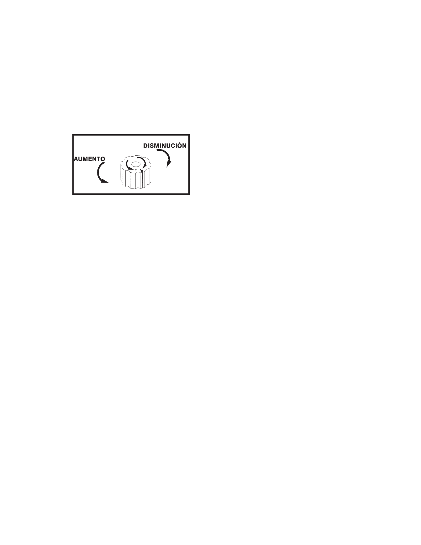
Manual del operador 55
LIMPIEZA CON DETERGENTES- PRESIÓN ALTA:
NOTA: Esta función está diseñada para ser usada únicamente con detergentes suaves. Dado que la solución
de limpieza viaja a través de la bomba y el serpentín del intercambiador de calor, no use corrosivos ya que
provocarán daño extenso y representan un peligro considerable.
1. Vea las advertencias de “Riesgo de lesiones”. Asegúrese de usar vestimenta protectora como se indicó.
2. Prepare la solución de detergente de acuerdo a las instrucciones en la etiqueta. (Nunca bombear ácidos, alcalinos,
uidos abrasivos o solventes por la unidad. Es recomiendo que use solamente detergentes ligeros con desconocidos
y muchas veces corrosivos de muchos detergentes poulares en la industría de limpiado de lavadores de presión.)
3. Usando el conector rápido, conecte bien la boquilla de rociado de detergente (#6540º NEGRA) al extremo de la
vara, con la pistola a gatillo asegurado en la posición “OFF”.
NOTA: Este sistema de inyección está diseñado para aplicar detergentes a baja presión solamente. No permitirá
que se introduzcan soluciones de detergente en el sistema a menos que la boquilla del detergente esté insta-
lada en la vara.
4. Sumerja completamente el extremo de la malla ltrante de la manguera de vinilo transparente en la solución de
detergente.
5. Para aplicar la solución, quite el seguro de la pistola active el gatillo. En unos cuantos momentos, una mezcla de
detergente y agua saldrá por la boquilla. Comience a rociar la porción inferior de la supercie que va a lavar y siga
en dirección ascendente, en pasadas largas, superpuestas. Aplicando de la parte inferior hacia arriba se evitan
manchas de escurrimientos. Permita que se remoje brevemente. Trate de no trabajar en supercies calientes o
expuestas a la luz directa del sol, para reducir las probabilidades de que el detergente se seque, lo cual podría
causar daños a la supercie. Asegúrese de aplicar la solución de limpieza a una pequeña sección a la vez.
6. Para enjuagar: je la pistola de gatillo en la posición de APAGADO. Cambiar la válvula de contador de detergente
a posición de OFF. Quite el seguro de la pistola y rocíe. Tomará aproximadamente 30 segundos para purgar todo
el detergente de la línea. Para lograr los mejores resultados de enjuague, comience en la parte superior y avance
en forma descendente.
7. Haga pasar por acción de sifón un galón de agua a través del sistema de inyección de detergente del sistema
después de cada uso. Esto evita la posibilidad de corrosión o acumulación de residuos de detergente, lo cual
provocaría problemas mecánicos durante el siguiente uso.
VÁLVULA DE CONTADOR DE
DETERGENTE
INSTRUCCIONES DE OPERACIÓN
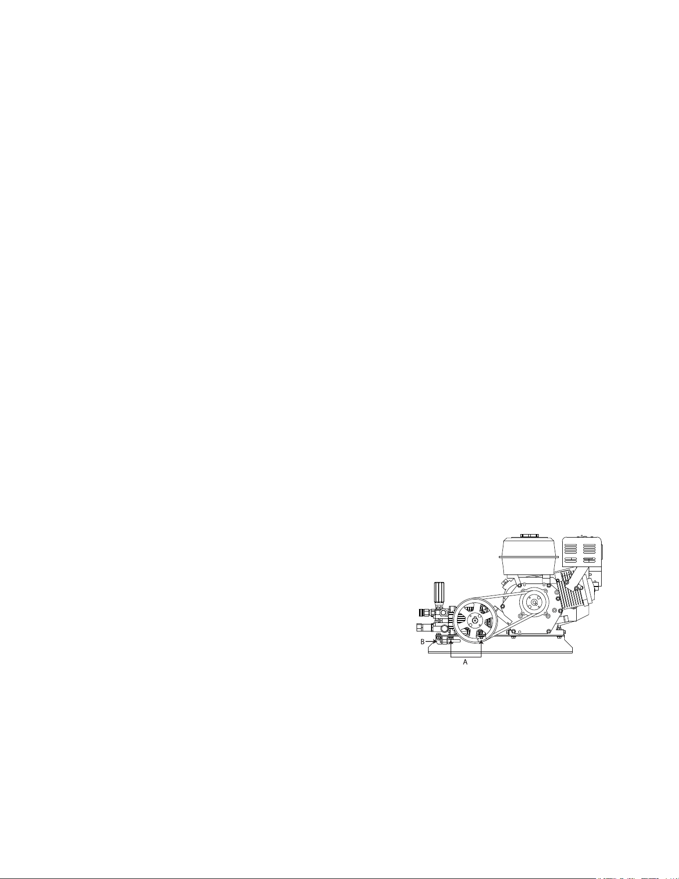
56 Manual del operador
MANTENIMIENTO ESPECIFICO:
COMPONENTES DE EMISIÓN EVAPORADO:
La unidad que compró incluir los components siguentes que son de acuerdo con los Estandardes de Emisión
Evaporado de todo California Air Resources Board de Estandardes de Emisión:
1. Manguera de combustible
2. Instalaciones de Manguera de combustible
Estos componenetes deben tener inspección en un base diario para grietas, agujeros y uso abnormal. Si ocurrió las
grietas, agujeros o uso abnormal, reemplace los components inmediatamente.
MOTOR: En el instructivo del motor que viene con su unidad se detallan los procedimientos especícos para dar
mantenimiento al motor. Si sigue las recomendaciones del fabricante prolongará la duración de su motor.
BOMBA:Cambie el aceite de la bomba después de 50 horas de operación. Después del cambio inicial, el fabricante
recomienda cambiar el aceite cada 3 meses o a intervalos de 250 horas. Si el aceite tiene aspecto sucio o lechoso,
quizá sea necesario hacer cambios más frecuentemente. Use aceite especial para bombas SAE20 o 30 non deter-
gente y solo llene hasta el centro de la mirilla de nivel. NO LLENE DEMASIADO.
BOQUILLA:El ujo de agua a través de la boquilla de rocío causará erosión del oricio, ensanchándolo y provocando
una pérdida de presión. Deben reemplazarse las boquillas siempre que la presión llegue al 85% del máximo. La fre-
cuencia del reemplazo depende de variables tales como el contenido mineral en el agua y la cantidad de horas que
se use la boquilla.
MANTENIMIENTO-CADA 3 MESES:
CAMBIAR ACEITE DE BOMBA DEL AGUA: Asegúrese de unidad está en posición de OFF. Cambiar aceite de
bomba despues de la cincuenta horas primeras de operación. Despues de cambio primero, cada y todo 3 meses o
intervalos de 500 horas es recomendado. Si aceite está sucio o lechoso, cambios puede necesitar en más frecuen-
cia. Use SAE20 o 30 aceite sin-detergente de bomba y llenar a medio de vidrio de ver de aceite. No llenar algo hast
el borde.
REEMPLAZAR BOQUILLA DE PRESIÝN ALTA: Flujo de agua por boquilla de atomizar erosionará el orico, este hará
más grande y resultará en perdida de presión. Debe reemplazar las boquillas cuandoquiera presión es menos de
85% de la maxima. La frecuencia de reemplazar es dependente de algunas variables como contenido de mineral en
el agua y el numero de usar de la boquilla.
INSPECCIÓN DE CORREA Para mantener la máxima eciencia de su lavadora de alta presión, puede ser necesario
ajustar la tensión de las correas ocasionalmente. Siga el procedimiento que se describe a continuación.
1. Quite el protector de correas y aoje las cuatro pernos que de la bomba
(Referencia A).
2. Gire el tornillo (Referencia B) en el sentido de las manecillas del reloj
hasta observar que la correa se exiona una 1/2 pulgada (1,3 cm) entre
las poleas.
3. Apriete las pernos (Referencia A).
4. Ponga una regla tocando el costado de ambas poleas. Si es necesario,
aoje los tornillos de una polea y muévala hacia adentro o hacia afuera
para que quede correctamente alineada. Apriete los tornillos de la polia
y verique otra vez la tensión.
5. Vuelva a poner la protección y apriete los sujetadores rmemente.
AJUSTADO DE AIRE DE QUEMADOR: La contra- ventana ha preprogramado en la fabrica para operación apro-
priado entre nivel del mar y elevación de 2000 pies en condiciones normales (temperaturas del aire y agua de 60° F).
En temperaturas más frio o altitudes más arribas, puede necesitar para ajustar el suministro del aire a la cámara de
combustión. Este ajustado maximizará la eciencia de quemador y evitar operación sin eciencia o cnatidad exceso
de hollín de rollo de intercambio de calor. Durante algo ajustado de contraventana del aire y bada es recomendado
para hacer un examen de humo. Si no tiene el equipo para hacer un examen de humo, siga los procedimientos
abajo.
1. La maquina necesita estar funcionando quemador en posición de "ON".
2. Suelte atornillo de cerradura (#3 en la izquierda en la contraventana.
3. Revisar para humo del exhosto de interambio de calor. Si no hay humo, cerrar la contraventana del aire muy
ALMACENAJE Y MANTENIMIENTO
AJUSTE DE TENSION DE CORREAS
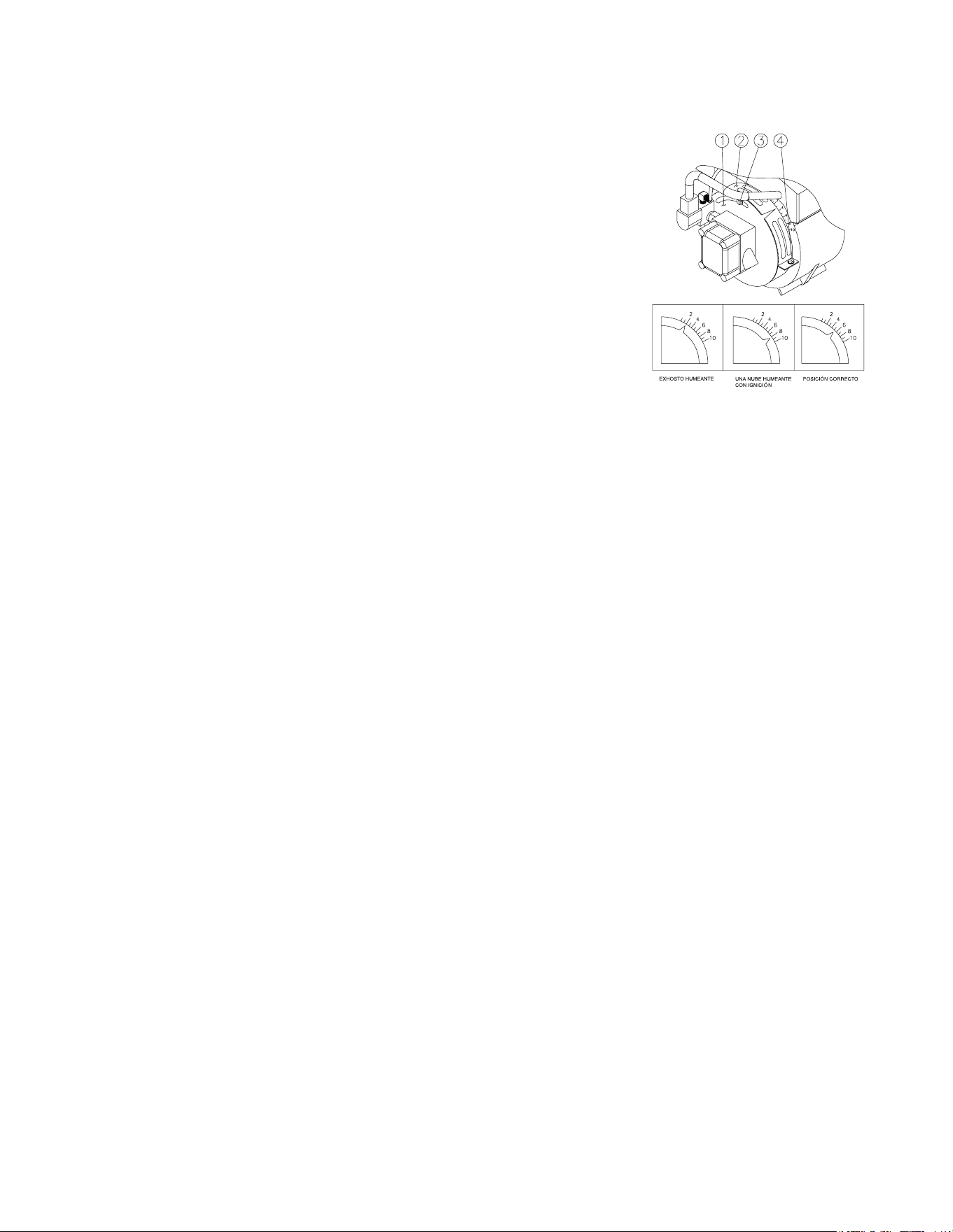
Manual del operador 57
ALMACENAJE Y MANTENIMIENTO
despacio (#1 en la izquierda) como moviendo el disco en sendo contrario
a las agujas del reloj a numero más bajo. Siga mover el disco hasta hay
humo.
4. Anotar este posición.
5. Abra la contraventana del aire (#1 en izquierda) de dos incrementos. Por ejemplo:
Si contraventa del aire fue en 2, la mueva a 4.
6. Mover muy despacio el gatillo de pistola a posición "ON" y "OFF". Este hará
quemador estar en posición ON y OFF. Vea para una nube de humo cuando
hay ignación de quemador.
7. Repetir numeros 5 y 6 hasta hay una nube de humo. Anotar posición de
contraventana del aire.
8. La diferencia entre las posiciones de anotar en numeros 4 y 7 es la ventana
de combustión. Ponga el disco en posición de medio manera entre de este
posiciones.
NOTA: Puede necesitar más o menos aire para tener una ventaña de com-
bustión correctos: no puede detectar un posición en peldaño numero 3
o 7. Suelte el tornillo (#4 a la izquierda) abra la Banda de Aire (#2 a la izquierda) en incrementos de 1/4".
Repite posiciones 3-8 hasta combustión correto ha logrado.
EXAMINE AGUA Y PRESIÓN DE COMBUSTIBLE: Estos procedimientos debe hacer de un tecnico de servicio que
tiene autoridad.
EXAMINE AGUA Y TEMPERATURA: Estos procedimientos debe hacer de un tecnico de servicio que tiene autori-
dad.
MANTENIMIENTO – CADA 6 MESES
REEMPLACE FILTRO DE COMBUSTIBLE – Siga las instrucciones se dan en ltro de combustible para procedimien-
to correcto.
MANTENIMIENTO – CADA 12 MESES
LIMPIAR EL ROLLO DE CAL – Una pérdida de presión puede signicar que el rollo necesita limpiar de cal. Haga este
procedimiento en base periódico.
1. Mezcla pelvo/solución de limpiado de cal en según a direcciones en paquete.
2. Quite la boquilla del bastón. Ponga una media de nylon encima de la asamblea del bastón para colectar desechos,
y entonces ponga la asamblea del bastón en tanque de otar.
3. Asegúrarse de que el gatillo de pistola está abierto y empezar el motor para permitir la circulacin del agua por el
sistema. Permitir est proceso seguir por 2-4 horas (consulte direcciones de paquete de agente de limpiar el cal
para tiempo exacto).
4. Cuando todo se completó, ponga el motor en posición de "OFF". Desague y limpie el tanque de otar, quite media
de nylon, y limpie la pistola y asamblea del bastón.
5. Limpie todo del sistema con agua limpiado y fresco y ponga la boquilla en asamblea del bastón.
6. Quite solución de limpiado de cal en según a regulaciónes de local, estado y federal.
EXAMINE EL VOLTAJE Y DECORRIDO DE AMPERIO: Use un metro del voltaje y amperio para examinar la maquiña
para voltaje y amperaje correcto. Este procedimiento debe hacer de un tecnico servicio con autoridad si no tiene
estos instrumentos o no ser asegúrese como hacer estos examines.
INSPECCIONE FILTRO INTERIOR DE BOMBA DE QUEMADOR DE COMESTIBLE: Este procedimiento debe hacer
de un tecnico de servicio con autoridad.
REVISE ELECTRODOS DE QUEMADOR: Este procedimiento debe hacer de un tecnico de servicio con autoridad.
REEMPLACE BOQUILLA DE COMESTIBLE: Este procedimiento debe hacer de un tecnico de servicio con autoridad.
MANTENIMIENTO - ESTACIONAL:
NOTA: La preparación apropiada para el invierno está basada en las instrucciones recomendadas del fabricante
incluidas en la “Tabla de Protección” mostrada en el rótulo posterior de la mayoría de los recipientes de anti-
congelantes.
PREPARACIÓN PARA EL INVIERNO: Será necesario preparar esta unidad para el invierno, para nes de Almace-
AJUSTADO DE AIRE DE QUEMADOR
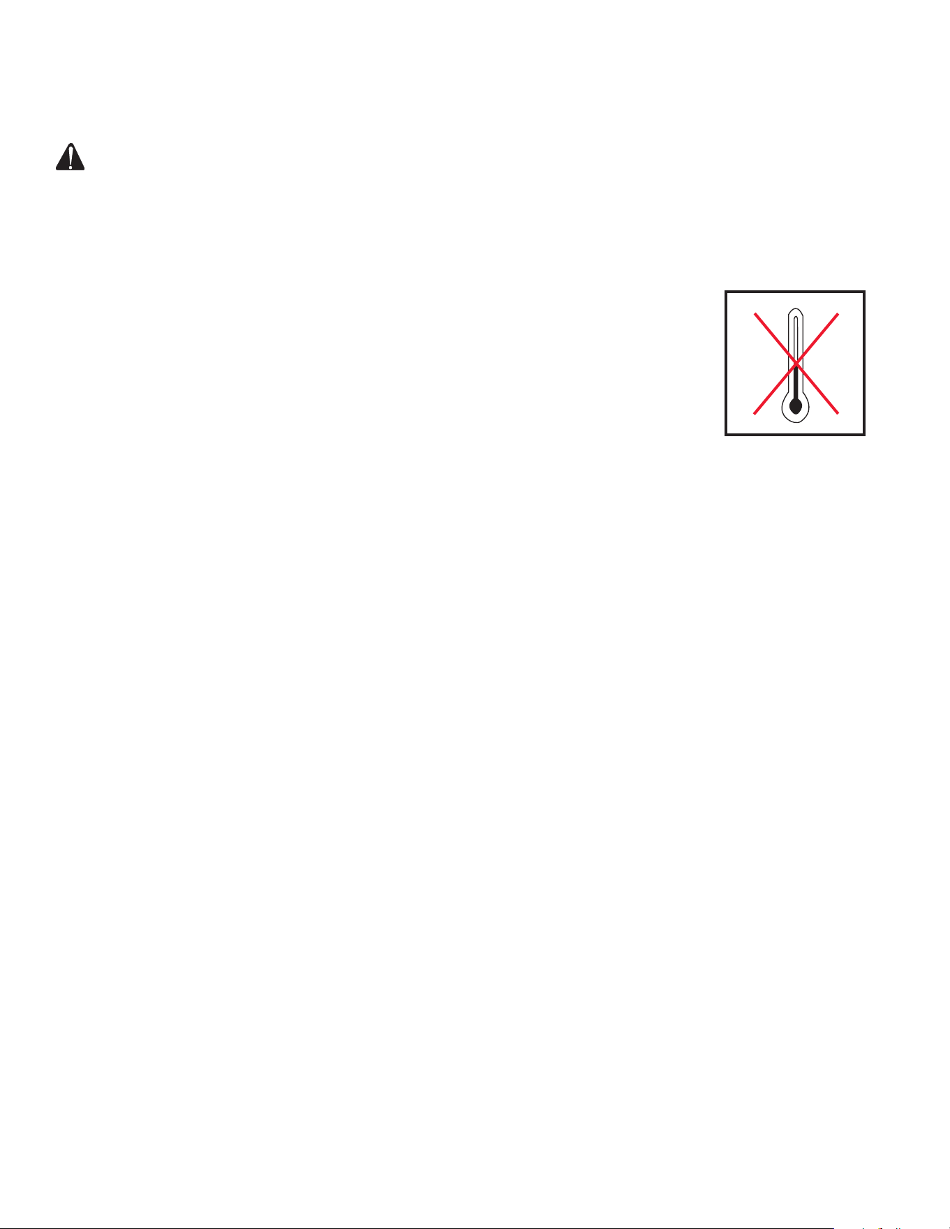
58 Manual del operador
namiento y transporte en temperaturas ambiente inferiores al punto de congelación. Esta unidad debe protegerse
contra la temperatura más baja incurrida por las siguientes razones:
ADVERTENCIA: ¡RIESGO QUE LA UNIDAD REVIENTE! ¡NO ALMACENE/OPERE LA UNIDAD EN UN
AMBIENTE HELADO!
1. Si se congela cualquier parte del sistema de bombeo puede acumularse una presión excesiva en la unidad, lo que
podría causar que la misma reviente resultando en lesiones posibles graves al operador o a los observadores.
2. El sistema de bombeo de esta unidad puede resultar dañado permanentemente si se congela. LOS DAÑOS POR
CONGELACION NO ESTAN CUBIERTOS POR LA GARANTIA.
Usted puede proteger su unidad siguiendo el procedimiento indicado abajo, si debe almacenarla en un lugar donde
la temperatura puede descender por debajo de los 32°F.
VOLARLE DEL AIRE:
1. Quite la boquilla de asamblea del bastón. Aprete el gatillo hasta nada agua sale la asamblea
del bastón.
2. Conecte instalación del aire de una manguera del aire a instalación de mallas en tanque de
otar o eslabón giratorio de la entrada.
3. Funcione aire compresado entre el sistema para evitar todo agua del sistema.
SOLUCIÓN DEL ANTICONGELANTE:
1. Reúne los artículos siguientes:
a. Dos recipientes de 5 galones.
b. Un galón de anticongelante. (Mi-T-M® recomienda un anticongelante seguro para el medio ambiente.)
c. Suministro de agua.
d. Una manguera de tres pies de largo con un D.I. de 1/2-3/4 y con un adaptador macho de manguera de jardín
de 3/4 de pulgada.
2. Procedimiento:
a. Para comenzar a preparar su unidad para el invierno, la misma debe hacerse funcionar y cebarse de acuerdo
con los “Procedimientos de Arranque” indicados.
b. Apague la unidad y corte el suministro de agua, después de hacerla funcionar y cebarla.
c. Elimine la presión del sistema apuntando la pistola a gatillo hacia una dirección segura y accionando el gatillo
hasta que el ujo de agua cese de salir por la boquilla.
d. Asegure la pistola a gatillo en la posición OFF y retire la boquilla.
e. En un recipiente de cinco galones, mezcla el anticon-gelante y água según las recomendaciones del fabricante
para la temperatura loque esta preparando para el invierno.
NOTA: La preparación apropiada para el invierno está basada en las instrucciones recomendadas del fabricante
incluidas en la “Tabla de Protección” mostrada en el rótulo posterior de la mayoría de los recipientes de anti-
congelantes.
f. Retire la manguera de suministro de agua de la unidad y je seguramente la manguera de 3 pies a la conexión
de entrada. Sumerja el otro extremo de la manguera del anticongelantes.
g. Apunte la vara hacia el recipiente vacío y arranque la unidad.
h. Accione el gatillo de la pistola hasta que el anticongelante comience a salir por la vara. Suelte el gatillo por 3
segundos, a continuación accione el gatillo de la pistola por 3 segundos. Continúe ciclando la pistola varias
veces hasta que toda la mezcla anticongelante es extraída del recipiente por la acción de sifón.
i. Apaque la unidad.
j. Separe la manguera de 3 pies de la unidad y drene todo el exceso restante de anticongelante dentro del reciente
de 5 galones.
k. Desconecte el conjunto de manguera/pistola/vara de la unidad y drene todo el exceso restante de anticongelante
dentro del recipiente de 5 galones.
l. Almacene la manguera, la pistola y vara junto con la unidad, en un lugar seguro.
m. Almecene la solución anticongelante para un uso ulterior o descártela de acuerdo con las leyes de protección
del medio ambiente correspondientes.
ALMACENAJE Y MANTENIMIENTO
32˚F 0˚C

Manual del operador 59
LOCALIZACION DE FALLAS
SINTOMA CAUSA PROBABLE SOLUCION
El motor no arranca. Problemas con el motor. Vea el manual del motor que viene con su uni-
dad.
Los componentes de la unidad están
congelados.
Permita que se descongele Si alguna parte de la
unidad se congela, es posible que se acumule
la presión, lo cual podría ocasionar que la unidad
reviente y consecuentemente provoque lesiones
graves al operador o las personas que se en-
cuentren alrededor.
No hay descarga de
la boquilla cuando se
acciona el mecanismo
del gatillo.
Suministro inadecuado de agua. Asegúrese que la manguera tenga 3/4" de diá-
metro y que el suministro de agua entrante esté
abierto.
Presión baja o uctu-
ante
Doblez en la manguera de entrada de
agua.
Elimine el doblez
Está obstruido el tamiz de la entrada
de agua.
Saque el tamiz, limpie o reemplace.
La bomba absorbe aire (Eliminado el
cebado)
Ajuste todas las conexiones de entrada de agua.
Elimine dobleces en la tubería de entrada.
No está en mode de presión alta. Introduce boquilla de presión alta.
La boquilla de rociado está obstruida
o gastada.
Mueva la empuñadura ajustable en lanza doble
en sentido contrario a las agujas del reloj a pre-
sión alta.
El conjunto de la válvula en la bomba
está dañado o obstruido.
Saque, limpie o reemplace.
Los empaques de la bomba están
gastados.
Saque, inspeccione, limpie o reemplace. Reem-
place los empaques.
La válvula de derivación no opera cor-
rectamente.
Repare o reemplace.
El aceite de la bomba
parece lechoso o espu-
moso.
Agua en el aceite Cambie la bomba de aceite. Llene al nivel apro-
piado.
Pérdida de aceite de la
unidad
Juntas o juntas tóricas desgastadas. Llame al Departamento de Servicio.
Agua está saliendo en
válvula de seguridad.
Mal funcionamiento de descargado. Detecte y corregir problema con descargado.
Mal funcionamiento del interruptor de
presión.
Detecte y corregir problema del interruptor de
presión.
Válvula de seguridad es defectivo. Reemplace válvula de seguridad. NUNCA
funciona unidad sin válvula de seguridad. Este
puede causar un explosión!

60 Manual del operador
LOCALIZACION DE FALLAS
SINTOMA CAUSA PROBABLE SOLUCION
Cuando la pistola de
gatillo está asegurado
en la posición “OFF”,
el agua uye desde la
boquilla.
La pistola funciona mal. Repare o reemplace.
Motor de calefactor no
funcionará. (quemador
no inamará sin funcio-
nando de calefactor)
Mal funcionamiento de quemador/cal-
efactor del motor.
Repare o reemplace.
Calefactor funciona,
pero quemador no
inamará.
Gatillo está cerrado. Abre el gatillo para presión.
No hay combustible. Más combustible.
Varilla de presion está fatigando. Presión debe estar más a 375 PSI a permetir
quemadura encender.
No hay voltaje Llame al Departamento de Servicio.
Insuciente o Inadecuado suminstro
de comestible.
Revise comestible para asegúrarse correcto. Si
es necesario desaguar el tanque y ltro y rellenar
con comestible apropriado.
Bomba combustible esta absorban-
dos el aire.
Apriete todas las conexiones de entrada de com-
bustible. Elimine las fugas en la línea de entrada.
Calefactor funciona
pero quemador no
inamará.
Filtro de comestible o seperador de
agua de comestible es sucio o ob-
struir.
Desague o reemplace como necesario
Insuciente presión de bomba de
comestible
Revise presión de bomba de comestible, ajuste
or reemplace como necesario..
No funcionamiento de bomba de
comestible
Revise presión, reemplace si necesario.
Pareado exible rompió. Reemplace
Falla de válvula de solenoide del
comestible.
Reemplace
Boquilla de comestible es sucio o
obstruir.
Reemplace boquilla de comestible.
Ajustado de quemador del aire incor-
recto.
Ajuste como ver en pagiña 78.
Módulo de ignición defectuosa. Repare o reemplace. Consulte su departamento
de servicio.
Ignition electrodes damaged or worn. Adjust or replace electrodes. Consult your Cus-
tomer Service.

Manual del operador 61
LOCALIZACION DE FALLAS
SINTOMA CAUSA PROBABLE SOLUCION
Calefactor funciona,
quemador inama pero
no calentará.
Insuciente o indadecuado suministro
de comestible.
Revise comestible para asegûrarse correcto. Si
es necesario desaguar el tanque y ltro y rellenar
con comestible apropriado.
Seperador de agua de comestible y
ltro de comestible es sucio o ob-
struir.
Desague o reemplace como necesario.
Insuciente presión de bomba de
comestible
Revise presión de bomba de comestible, ajuste o
reemplace si necesario.
Boquilla de comestible es sucio o
obstruir
Reemplace la boquilla de comestible
Ajustado de quemador del aire incor-
recto.
Ajuste.
Acumulación de sarro en rollo de
intercambio de calor.
Consulte departamento de servicio.
Quemador funciona
irregularamente.
Agua está en aceite de comestible. Reemplace ltro de comestible o desague
seperador de agua de comestible, desague
tanque de comestible y reemplace con comes-
tible limpiado.
Filtro de comestible o seperador de
agua de corriestible es sucio.
Reemplace el elemento.
Boquilla de comestible es sucio. Reemplace
Posición de ajustado del aire es incor-
recto.
Ajuste
Mal funcionamiento de bomba de
comestible.
Reemplace
Insucicinte comestible. Rellene. Si fumo blanco siga, consulte departa-
mento de servicio.
Quemador despide
fumo blanco.
Demasiado suminsitro del aire. Ajuste
Quemador despide
fumo negro.
Insuciente suminsitro del aire. Ajuste
62 Manual del operador
TABLA DE MANTENIMIENTO DEL REMOLQUE
Presión de los neumáticos Inar a la presión adecuada indicada en la
pared lateral.
En Cada Viaje
Arandelas, pernos y tuercas
de las ruedas
Apriete a las especicaciones de torsión adec-
uadas.
Cada 3000 millas o 3 meses.*
Rueda Compruebe que no hayan daños o defectos de
circularidad.
Cada 6000 millas o 6 meses.
Acoplador de bola Compruebe que tenga suciente aceite. En Cada Viaje
Verique el mecanismo de bloqueo.
Compruebe que no haya desgaste inusual.
Cadenas de seguridad en la
Bola de Enganche
Verique la abrasión, distorsión e integridad
general de los enlaces.
En Cada Viaje
Acoplador Verique que el perno de enganche este
apropiadamente apretado, bien posicionado y
seguro.
En Cada Viaje
Distribución de Carga Verique la distribución de la carga y seguri-
dad.
En Cada Viaje
Soldaduras Verique que todas las soldaduras no tengan
grietas o separaciones.
Cada 6000 millas o 6 meses.
Electricidad: Luces y Señales Verique que estén funcionando apropiada-
mente. Sustituya las bombillas quemadas.
En Cada Viaje
Buje, Rodamiento y Sello de
Eje
Verique que los bujes no estén gastados,
estén lo sucientemente engrasados, que el
rodamiento tenga buen movimiento y que los
sellos no tengan grietas.
Cada 3000 millas o 3 meses.
*Revise que las tuercas estén bien apretadas antes del viaje inicial, nuevamente a las 25 millas y otra vez en
100 millas. Vuelva a revisarlas al menos cada 3 meses o 3000 millas.
Manual del operador 63
TABLA DE MANTENIMIENTO
* Debe realizar esto un técnico de servicio autorizado.
** Ud. tiene que cambiar combustible de bomba despúes de las primaras cincuenta (50) horas. De la operación
y cada (250) horas o 3 meses, cualquiera.
*** Las boquillas de alta presión deben reemplazarse siempre que la presión sea inferior al 85%.
**** Hay una diferencia con la acumulación de escama con minerales en el agua y la cantidad de usos. Tienen
que quitar escama cada mes o cada año.
***** El aceite del motor debe cambiarse despúes de las primeras 8 horas de operación y cada 50 horas o 3
meses, lo que ocurra primero.
PROCEDIMIENTO DIARIAMENTE
3 MESES 6 MESES 9 MESES 12 MESES
Examine del nivel de aceite del motor
X
Comabie del aceite del motor*****
X X X X
Examine nivel del petroleo bomba
X
Combie petroleo de bomba**
X X X X
Examine ltración de petroleo
X
Examine ltración de combustible
X
Examine ltración del agua
X
Examine la manguera
X
Examine la pantalla de entrada de agua
X
Examine ltro combustible
X X X X
Reemplace ltro combustible
X X X
Examine de correas
X X X X
Reemplace las boquilla de presión alta***
X X X X
Reemplace ltro de bomba combustible*
X
Reponga tobera combustible*
X
Examine aire quemadura regulable
X
Examine quemadura electrodos*
X X X X
Pruebe la presión del agua*
X
Pruebe la presión de combustible*
X X X X
Pruebe temperatura del agua*
X X X X
Quite escama del rollo****
X X X X

64 Manual del operador
DECLARACIÓN DE GARANTÍA DE LA SERIE HDC
Fabricante garantiza todas las piezas (excepto las piezas a las cuales se hace referencia más
abajo) de su nueva lavadora a presión SERIE HDC contra defectos en sus materiales o su
manufactura durante los períodos siguientes:
Para vida:
Colector de bomba
Por diez (10) años a partir de la fecha original de compra:
La bomba de alta presión (Bomba General sólo)
Por siete (7) años a parir de la fecha de compra:
La bomba de presión alta (Bomba AR sólo)
Por cinc (5) años a parir de la fecha de compra:
Pollo de intercambiador de calor
Por dos (2) años a parir de la fecha de compra:
Estructura Quemador
Protecciones Polea
Tubería
Por seis (6) meses a parir de la fecha de compra:
Motor de quemador Transformador de ignición
Por noventa (90) días a parir de la fecha de compra:
Interruptores de contról Interruptores de seguridad
Válvula de descargar Bomba de combustible
Capacidor
Por treinta (30) días a parir de la fecha de compra:
Mangueras de alta presión Gatillo de pistola
Mallas / Filtros
Durante el período de garantía, se repararán o reemplazarán a discreción de fabricante las
piezas defectuosas que no estén sujetas a un desgaste normal. El reembolso en cualquier caso
se limitará al precio de compra.
EXCLUSIONES
1. El motor está cubierto bajo una garantía por separado que su respectivo fabricante ofrece y
queda sujeto a los términos establecidos en dicha garantía.
2. Piezas sujetas a desgaste normal:
Empaques de la bomba Boquillas atomizadoras
Válvulas de la bomba Conectores roscados
Válvulas de detergente Filtros de combustible
Argolla Correas
3. Esta garantía no cubre piezas dañadas a causa de desgaste normal, aplicación incorrecta,
uso incorrecto, o operación a velocidades, presiones o temperaturas diferentes a las recomen-
dadas. Tampoco se garantizan las piezas dañadas o desgastadas debido al uso de líquidos
cáusticos o a la operación en ambientes abrasivos o corrosivos, o bajo condiciones que causen
cavitación de la bomba. También se anula la garantía si no se siguen los procedimientos reco-
mendados de operación y mantenimiento.
4. El uso de piezas que no sean genuinas anulará la garantía. Las piezas enviadas con porte
prepagado a la fábrica de fabricante o a un centro de servicio autorizado serán inspeccionadas
y reemplazadas sin cargo alguno si se encuentran defectuosas y están cubiertas por la garantía.
No hay otras garantías que se extiendan más allá de la descripción presentada aquí. Fabricante
no será responsable bajo ninguna circunstancia por pérdida de uso del aparato, pérdida de
tiempo o renta, inconveniencia, pérdida comercial o daños consecuentes.

Manual del operador 65
D
D
E
E
C
C
L
L
A
A
R
R
A
A
C
C
I
I
O
O
N
N
D
D
E
E
C
C
O
O
B
B
E
E
R
R
T
T
U
U
R
R
A
A
D
D
E
E
E
E
M
M
I
I
S
S
I
I
O
O
N
N
E
E
S
S
D
D
E
E
C
C
A
A
L
L
I
I
F
F
O
O
R
R
N
N
I
I
A
A
S
S
U
U
S
S
D
D
E
E
R
R
E
E
C
C
H
H
O
O
S
S
D
D
E
E
G
G
A
A
R
R
A
A
N
N
T
T
I
I
A
A
Y
Y
O
O
B
B
L
L
I
I
G
G
A
A
C
C
I
I
O
O
N
N
E
E
S
S
La Tabla de Recursos Aéreos de California y el fabricante están felices para explicar la garantía de sistema de control de emisiones
en su 2022/2023 modelo del pequeño motor todoterreno (PMT). En California, Pequeños Motores Todoterreno (PMTs) nuevos
tienen que ser diseñados, construidos y equipados para conformar a los estándares rigurosos de no-niebla con humo del estado. el
fabricante debe justificar el sistema de control de emisiones en su PMT por los períodos de tiempo indicados abajo a condición que
no ha habido abuso, negligencia ni el mantenimiento impropio de su PMT.
Su sistema de control de emisiones puede incluir partes como el carburador, sistema de inyección de combustible, sistema de
ignición, catalizador, tanques de combustible, líneas de combustible, capas de combustible, válvulas, botes, filtros, mangueras de
vapor, abrazaderas, conectores, y otros componentes asociados relatados a la emisión. Donde existe una condición de la garantía,
el fabricante reparará su PMT en ningún costo a usted, incluyendo diagnóstico, las piezas, y trabajo.
COBERTURA DE GARANTIA DE FABRICANTE
Este sistema de control de emisiones tiene garantía durante dos años. Si cualquier parte que está relacionada a emisiones en su
motor es defectuosa, la parte será reparada o será reemplazada por el fabricante.
RESPONSABILIDADES DE GARANTIA DEL PROPIETARIO
-Como el propietario del Pequeño Motor Todoterreno, usted es responsable de la ejecución del mantenimiento necesario indicado
en su manual de propietario. El fabricante recomienda que usted retenga todos recibos sobre el mantenimiento de su PMT, pero el
fabricante no puede negar de garantía solo para la falta de recibos.
-Como el propietario del Pequeño Motor Todoterreno, usted debe saber que el fabricante puede negar cobertura de garantía si su
Pequeño Motor Todoterreno o una pieza ha fracasada a causa de abuso, negligencia o el mantenimiento impropia o las
modificaciones desaprobadas.
-Usted es responsable de presentar su Pequeño Motor Todoterreno al centro de distribución o centro de reparaciones autorizado
por el fabricante, 50 Mi-T-M Drive, Peosta, IA 52068 (Mi-T-M) en pronto que un problema exista. Las reparaciones de garantía
deben ser completadas en una cantidad razonable de tiempo, no exceder 30 días.
Si usted tiene una pregunta con respecto a su cobertura de garantía, usted debe contactar el Departamento de Servicio para
Clientes en 1-800-553-9053 o por correo electrónico a corp@mitm.com.
C
C
O
O
B
B
E
E
R
R
T
T
U
U
R
R
A
A
G
G
E
E
N
N
E
E
R
R
A
A
L
L
D
D
E
E
G
G
A
A
R
R
A
A
N
N
T
T
I
I
A
A
D
D
E
E
E
E
M
M
I
I
S
S
I
I
O
O
N
N
E
E
S
S
-
-
S
S
ó
ó
l
l
o
o
C
C
a
a
l
l
i
i
f
f
o
o
r
r
n
n
i
i
a
a
-
-
El fabricant ejustifica al último comprador y cada comprador subsiguiente que el Pequeño Motor Todoterreno PMT (1) ha sido
diseñado, construido y equipado para conformarse con todas regulaciones aplicables; y (2) es libre de defectos en materias y
disfraza que causa el fracaso de una pieza garantizado conformarse con esas regula
ciones como puede ser aplicable a los
términos y condiciones que son indicados abajo.
(a) El período de garantía empieza en la fecha que el motor está entregado a un último comprador o cuando está primero puesto en
servicio. El período de garantía es dos años.
(b) Sujeto a ciertas condiciones y exclusiones como indicadas abajo, la garantía de piezas relatadas a emisiones es el siguiente:
(1) Cualquier pieza garantizada que no está programado para el reemplazo como mantenimiento necesario en su manual de
propietario está garantizado para el período de garantía indicado arriba. Si la pieza fracasa durante el período de cobertura
de garantía, la pieza será reparada o será reemplazada por el fabricante según la subdivisión (4) abajo. Cualquiera pieza
reparada o reemplazada bajo la garantía será garantizada para el resto del periodo.
(2) Cualquier pieza garantizada que está programada sólo para inspección regular en su manual de propietario está garantizada
para el período de garantía indicada arriba. Cualquiera pieza reparada o reemplazada bajo la garantía será garantizada por el
resto del período de garantía.
(3) Cualquier pieza garantizada que está programada para el reemplazo como mantenimiento necesario en su manual de
propietario está garantizado para el período del tiempo antes de la primera fecha planificada de reemplazo para esa pieza. Si
la pieza fracasa antes del primer reemplazo planificado, la pieza será reparada o será reemplazada por el fabricante según la
subdivisión (4) abajo. Cualquiera pieza reparada o reemplazada bajo la garantía será garantizada por el resto del período de
garantía antes del primer punto planificado de reemplazo para la pieza.
(4) Reparación o el reemplazo de alguna pieza garantizada bajo las provisiones de garantía en este debe ser realizado en una
estación de garantía sin cargo al propietario.
(5) Sin prejuicio de lo dispuesto en esta, los servicios de garantía y de reparación serán proporcionados en todos nuestros
centros de distribución que tengan la franquicia para atender a los motores sujetos.
(6) El propietario no debe ser cargado para trabajo diagnóstico que lleva a la determinación que una pieza garantizada es de
hecho defectuosa, con tal de que el trabajo diagnóstico sea realizado en una estación de garantía.
(7) A través del período de garantía de motor que está indicado arriba, el fabricante mantendrá un suministro de piezas
garantizadas suficientes para satisfacer la demanda esperada para tales partes.
(8) Cualquier pieza reemplazada puede ser utilizada en la ejecución de cualquier mantenimiento de garantía o reparaciones y
debe ser proporcionado sin cargo al propietario. Tal uso no reducirá las obligaciones de garantía de el fabricante.

66 Manual del operador
(9) Las piezas añadidas o modificadas que no están eximidas por la Tabla de Recursos Aéreos no pueden ser utilizadas. El uso
de cualquier pieza a
ñ
adida o modificada que no está eximida por el último comprador será razón para no permitir o aceptar
un reclamo de la garantía. El fabricant eno será responsable a garantizar los fracasos de piezas garantizadas causados por el
uso de una pieza a
ñ
adida o modificada que no está eximida.
(10) el fabricante proporcionará cualquier documento que describa los procedimientos o políticas de garantía de el fabricante
dentro de los cinco días hábiles posteriores a la solicitud del Director Ejecutivo.
(C) Piezas que tienen Garantía
La reparación o el reemplazo de cualquier parte garantizada de otro modo elegible para la cobertura de garantía pueden ser
excluidos de tal cobertura de garantía si el fabricante demuestra que el motor ha sido abusado, descuidado, o mantenido
incorrectamente, y que el abuso, negligencia, o mantenimiento impropio fue el causo directo de la necesidad para la reparación
o reemplaza de la pieza. Sin embargo, cualquier ajuste de un componente que tiene un dispositivo de la limitación de ajuste
que ha sido instalado por la fábrica y está funcionando apropiadamente todavía está elegible para la cobertura de la garantía.
Las siguientes piezas de garantía de emisiones están garantizadas:
(
1) Tanque de Combustible
(2) Tapa de Tanque de Combustible
(3) Líneas de Combustible (para combustible líquido y vapores de combustible)
(4) Accesorios de Líneas de Combustible
(5) Abrazaderas*
(6) Válvulas Limitadoras de Presión*
(7) Válvulas de Control*
(8) Control de Solenoides*
(9) Controles Electrónicos*
(10) Diafragmas de Control de Vacío*
(11) Cables de Control*
(12) Enlaces de Control*
(13) Válvula de Purga*
(14) Juntas*
(15) Separador de Liquido/Vapor
(16) Depósito De Carbón
(17) Depósito de Soporte de Montaje
(18) Conector de Puerto de Purga del Carburador
*Nota: Al estar estos relacionados con el sistema de control de emisiones por evaporación.

Manual del operador 67