
Mi-T-M
®
WCP Automatic Backwash Series Operator's Manual 1
OPERATORS MANUAL FOR Mi-T-M
®
WCP AUTOMATIC
BACKWASH SERIES
WATER RECYCLING TREATMENT SYSTEM
©Copyright 2005, Mi-T-M Corporation® Form #37-0728-030922
CAUTION
RISK OF INJURY!
READ MANUAL BEFORE OPERATING!
This manual is an important part of the water recycling treatment system and must remain with
the unit when you sell it!

2 Mi-T-M
®
WCP Automatic Backwash Series Operator's Manual
WARNING: This product can expose you to
chemicals including carbon monoxide, which is
known to the State of California to cause birth
defects or other reproductive harm. For more
information go to www.P65Warnings.ca.gov
WARNING
WARNING: This product can expose you to
chemicals including Lead, which is known to
the State of California to cause cancer and birth
defects or other reproductive harm. For more
information go to www.P65Warnings.ca.gov
WARNING
Contents
INTRODUCTION .............................................................................................................................. 3
SPECIFICATIONS ............................................................................................................................ 4
FLOW DIAGRAM ............................................................................................................................. 8
FLOW DIAGRAM ............................................................................................................................. 9
FEATURES FOR WCP-10AB ........................................................................................................ 10
FEATURES FOR WCP-10AB ........................................................................................................ 11
FEATURES FOR WCP-30AB ........................................................................................................ 12
FEATURES FOR WCP-30AB ........................................................................................................ 13
INSTALLATION .............................................................................................................................. 14
PRE-OPERATION CHECKLIST .................................................................................................... 17
PREPARATION .............................................................................................................................. 18
OPERATION .................................................................................................................................. 32
MAINTENANCE ............................................................................................................................. 33
TROUBLESHOOTING ................................................................................................................... 47
Mi-T-M
®
WCP Automatic Backwash Series Operator's Manual 3
Congratulations on the purchase of your new Mi-T-M water recycling treatment system! You can be assured your Mi-T-M
water recycling treatment system was constructed and designed with quality and performance in mind. Each component
has been rigorously tested to ensure the highest level of acceptance.
This operator's manual was compiled for your benet. By reading and following the simple safety, installation, opera-
tion, maintenance and troubleshooting steps described in this manual, you will receive years of trouble free operation
from your new Mi-T-M water recycling treatment system. The contents of this manual are based on the latest product
information available at the time of publication. Mi-T-M reserves the right to make changes in price, color, materials,
equipment, specications or models at any time without notice.
! IMPORTANT !
These paragraphs are surrounded by a "SAFETY ALERT BOX". This box is used to designate
and emphasize Safety Warnings that must be followed when operating this water recycling
treatment system.
Accompanying the Safety Warnings are "signal words" which designate the degree or level
of hazard seriousness. The "signal words" used in this manual are as follows:
DANGER: Indicates an imminently hazardous situation which, if not avoided, WILL
result in death or serious injury.
WARNING: Indicates a potentially hazardous situation which, if not avoided, COULD
result in death or serious injury.
CAUTION: Indicates a potentially hazardous situation which, if not avoided MAY
result in minor or moderate injury.
The symbols set to the left of this paragraph are "Safety Alert Symbols". These symbols
are used to call attention to items or procedures that could be dangerous to you or other
persons using this equipment.
ALWAYS PROVIDE A COPY OF THIS MANUAL TO ANYONE USING THIS EQUIPMENT. READ
ALL INSTRUCTIONS BEFORE OPERATING THIS WATER RECYCLING TREATMENT SYSTEM
AND ESPECIALLY POINT OUT THE "SAFETY WARNINGS" TO PREVENT THE POSSIBILITY
OF PERSONAL INJURY TO THE OPERATOR.
Once the unit has been removed from the crate, immediately write in the serial number of your unit in the space provided
below.
SERIAL NUMBER_________________________________
Inspect for signs of obvious or concealed freight damage. If damage does exist, le a claim with the transportation
company immediately. Be sure that all damaged parts are replaced and that the mechanical and electrical problems
are corrected prior to operation of the unit. If you require service, contact Mi-T-M Customer Service at 1-800-553-9053
for the Sales or Service Center nearest you.
Please have the following items available for all Service calls:
1. Model Number
2. Serial Number
3. Date and Place of Purchase
INTRODUCTION

4 Mi-T-M
®
WCP Automatic Backwash Series Operator's Manual
CONTENTS OF WCP-SERIES WATER RECYCLING TREATMENT SYSTEM
Carefully unpack your new Mi-T-M WCP-Series Water recycling treatment system. Check the contents against the
packing list. Contact the freight line if a damage claim is required on any component. The following items are the basic
equipment sent with your WCP-Series Water recycling treatment system.
SPECIFICATIONS
2. Sump Pump
3. Three Unattached Floats for Sump Pit
a. Blue: Protects sump pump low level.
b. Red: To ll pit from the water recycling treatment
system.
c. Green: High pit level discharge.
4. Sludge Tub w/ Bags
5. Sludge Hose
6. Water Test Kit
7. Manual
8. pH Sensor Probe
9. ORP Sensor Probe
1. Water recycling treatment system Platform
a. Clarier Type Oil/Solids Separator
1. Clarier Tank
2. Tank Stand
b. Ozone Generator
c. Ozone Pump
d. Filter Pump
e. Inlet Flow Meter
f. Filter Flow Meter
g. Multi-Media Filter
h. Polishing Filter
i. Transfer Pump
j. Pressurized Water Storage Tank
k. Waste Oil Decanter
Model WCP-10AB-0M10/0M30 WCP-30AB-0M10/0M30
Max Flow 10 GPM 30 GPM
Electrical- Single Phase 230V 30 Max Amps 37 Max Amps
Electrical- Three Phase 208/230V 16 Max Amps 20 Max Amps
Electrical- Three Phase 460V 8 Max Amps 10 Max Amps
Sump Pump1 HP 1 HP
Ozone Generator Low Flow Medium Flow
Ozone Pump 1/2 HP 1/2HP
Clarifi er Capacity 300 Gallons 600 Gallons
Oil Coalescing Area 275 Square Feet 425 Square Feet
Filter Pump1 HP 1-1/2 HP
Multi-media Filter Media 350 LBS 900 LBS
Polishing Filter Media 110 LBS 165 LBS
Transfer Pump 3/4 HP 2 HP
Dimensions 96”X60”X101” 108”X84”X110”
New Weight 2400 lbs 3225 LBS
Mi-T-M
®
WCP Automatic Backwash Series Operator's Manual 5
IMPORTANT SAFETY WARNINGS
WARNING: When using this product, basic precautions should always be observed, including the following:
READ ALL SAFETY WARNINGS BEFORE USING WATER RECYCLING TREATMENT SYSTEM
POTENTIAL CONSEQUENCE PREVENTION
Serious injury or death could occur if
the water recycling treatment system
is not properly grounded. Your
water recycling treatment system
is powered by electricity and may
cause electric shock or electrocution
if not installed properly.
Installation of this unit, including all electrical
connections, must comply with all local, state
and national codes.
This product must be grounded. Connect to a
GFCI circuit breaker when available. If the unit
should malfunction or breakdown, grounding
provides a path of least resistance for electric
current to reduce the risk of electric shock. Do
not ground to a gas supply line.
Improper connection of the equipment-
grounding conductor can result in a risk of
electrocution. Check with a qualied electrician
or service personnel if you are in doubt as to
whether the system is properly grounded.
Always be certain the unit is receiving proper
voltage (+/- 5% of the voltage listed on the
nameplate). Before installing electrical
connections, be certain the power switches
are in the "OFF" position.
Keep all connections dry and o the ground.
DO NOT allow metal components of the water
recycling treatment system to come in contact
with live electrical components.
Never operate the water recycling treatment
system with safety guards/covers removed
or damaged. Ensure all electrical covers are
securely in place when unit is operating.
Any electrical wiring or repairs performed on
this water recycling treatment system should
be done by Authorized Service Personnel in
accordance with National and Local electrical
codes.
Before opening any electrical enclosure,
always shut o the water recycling treatment
system and drain the water. Disconnect the
water recycling treatment system from the
power source. If the power disconnect is not
in sight, lock it in the open position and tag
it to prevent power usage. (Never assume
the water recycling treatment system is safe
to work on just because it is not operating, it
could restart at any time! Always disconnect
from the power source.)
RISK OF ELECTRIC SHOCK
OR ELECTROCUTION
HAZARD
Electrical shock may occur if water
recycling treatment system is not
operated properly.
Serious injury or death may occur if
electrical repairs are attempted by
unqualied persons.
6 Mi-T-M
®
WCP Automatic Backwash Series Operator's Manual
Never allow any part of your body to contact
the electrical motor until cooled.
POTENTIAL CONSEQUENCE
PREVENTION
IMPORTANT SAFETY WARNINGS
READ ALL SAFETY WARNINGS BEFORE USING WATER RECYCLING TREATMENT SYSTEM
RISK OF EXPLOSION OR FIRE
Serious injury or death could occur
from an explosion or re caused
by a system electric spark.
This unit must be placed in an area that is
well ventilated, free of ammable vapors,
combustible dust, gases or other combustible
materials.
HAZARD
RISK OF BURNS
Serious injury may occur from
touching the electrical motor.
This area can remain hot for
some time after the water
recycling treatment system is
shutdown.
RISK OF BURSTING
Serious injury or death could occur
from bursting caused by excessive
pressure in the system.
Do not mistreat the pressure gauges on the
system. Pressure gauges will malfunction
if they are subjected to excessive pressure,
vibration, pulsation or temperature or if they
are placed in an environment which causes
corrosion of parts. Incorrect readings on a
pressure gauge could mislead the operator and
place him in a dangerous working condition.
Do not use a booster pump or any type of
additional pumping system. Pressurizing the
suction of the pump may cause the pump body
to explode.
Do not use this water recycling treatment
system to pump ammable material! An
explosion could occur from a gas vapor buildup
inside the system.
In freezing temperatures, the unit must always
be warm enough to ensure there is no ice
formation in the pump. Do not start the water
recycling treatment system if it has been in a
freezing environment without rst allowing the
pump to thaw.
Serious injury may occur if
attempting to start the water
recycling treatment system when
the pump is frozen.
Mi-T-M
®
WCP Automatic Backwash Series Operator's Manual 7
RISK OF BODILY INJURY
Injury may occur from the water
recycling treatment system.
!SAVE THESE INSTRUCTIONS!
POTENTIAL CONSEQUENCE
PREVENTION
IMPORTANT SAFETY WARNINGS
READ ALL SAFETY WARNINGS BEFORE USING WATER RECYCLING TREATMENT SYSTEM
DO NOT DRINK THE WATER IN THE
WATER RECYCLING TREATMENT
SYSTEM!! This is non-potable water and is
not suitable for consumption.
The Cartridge Filter operates under pressure.
DO NOT attempt to loosen the locking ring or
open the lter tank unless the pump is turned
o an the air relief valve is opened.
DO NOT allow children to operate this unit.
DO NOT overreach or stand on unstable
support.
Wet surfaces can be slippery, wear protective
foot gear and keep good footing and balance
at all times.
Know how to stop the water recycling treatment
system. Be thoroughly familiar with controls.
Before servicing, ALWAYS shut o the water
recycling treatment system.
Never use any solvents or highly corrosive
detergents or acid type cleaners with this water
recycling treatment system.
Keep all chemicals out of the reach of
children!
Consult Material Safety Data Sheets for safe
handling of chemicals used with your system,
especially oxidizers and acids.
Serious injury may occur to the
operator from moving parts on the
water recycling treatment system.
Do not operate the unit without all
protective covers in place.
Follow the maintenance instructions
specied in the manual.
RISK FROM MOVING PARTS
Injury may occur from chemicals
contacting the skin.
HAZARD
8 Mi-T-M
®
WCP Automatic Backwash Series Operator's Manual
FLOW DIAGRAM
FLOW DIAGRAM WCP-30AB-011302-KS

Mi-T-M
®
WCP Automatic Backwash Series Operator's Manual 9
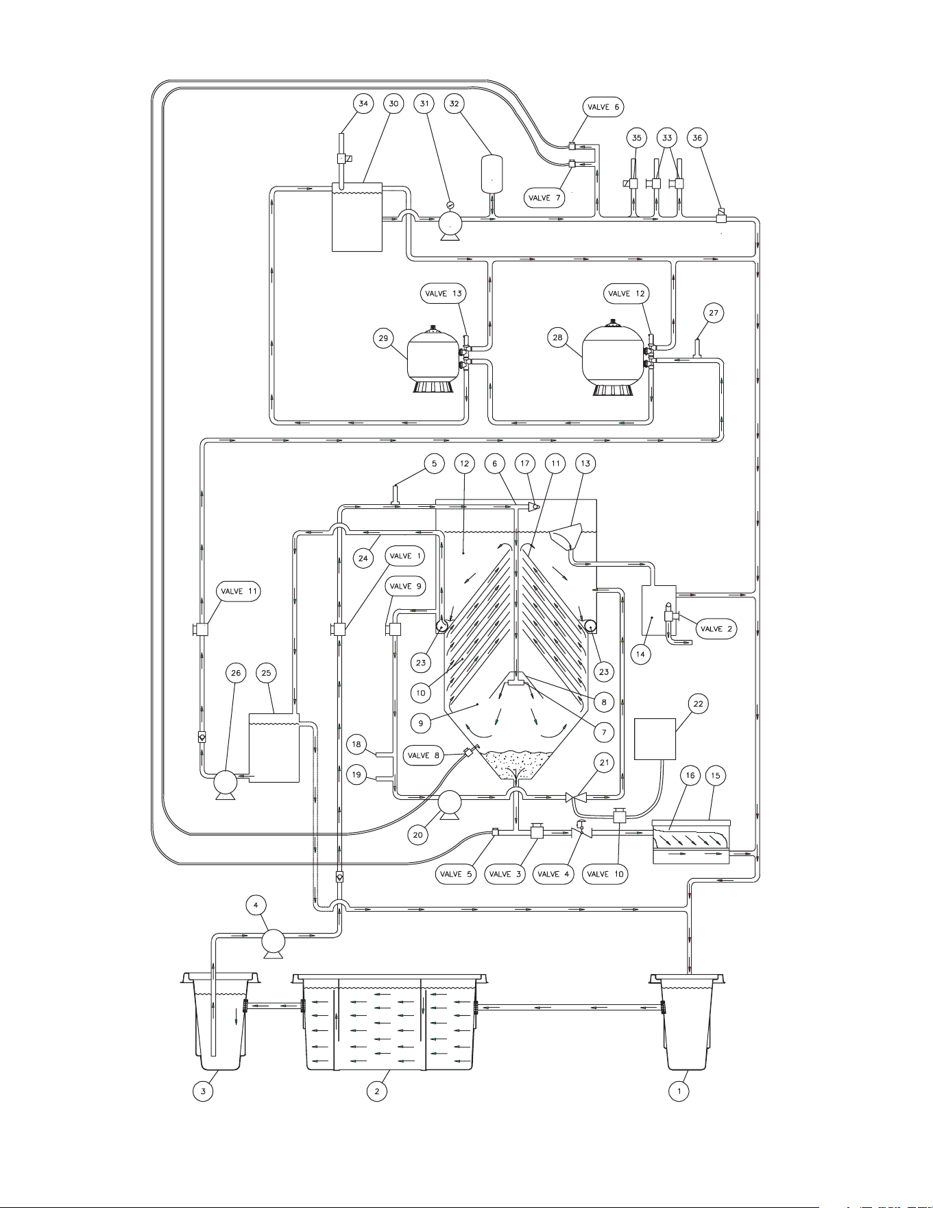
As pressure washers are being operated, used water ows into the Wash Water Catch Pit (1). From there, it moves
to the 3-Stage Collection Pit (2). Heavy debris falls to the bottom of the pit where it is trapped by a weir which is
designed to stop heavy debris while allowing the remaining water to move into the Sump Pit (3). The Sump Pump (4)
draws water from the Sump Pit (3) and brings it through the Water Inlet Flow Control Valve 1. This adjustable valve
is used to regulate the ow of water entering the water clarication tank. A Flow Meter (5) is positioned just ahead of
the water clarication tank. The water enters the water clarication tank through the Inlet Tee (6) and is directed down
to the Diverter Tee (7). From there the water is deected downward by the Solids Deection Cone (8), then to the
Solids Separation Chamber (9). The Solids Separation Chamber (9) allows the velocity of the water to slow so that
any suspended solids settle to the bottom. The water then rises up through the Oil Coalescing Cones (10).
1) The non-emulsied oil molecules in the water adhere to the Oil Coalescing Cones (10). When
enough oil molecules attach to each other, they form oil droplets. The oil droplets are carried along
with the water through the Top Separator Cone (11) and into the Oil Separation Chamber (12),
where the oil droplets oat to the surface. The Oil Skimmer (13) is positioned near the top of the Oil
Separation Chamber (12) which allows the thin layer of surface oil and water to drain into the Waste
Oil Decanter (14). Since oil is lighter than water, the oil oats to the top and is released from the
Waste Oil Decanter (14) when the Waste Oil Release Valve 2 is opened. Excess water is returned
to the Wash Water Catch Pit (1).
2) The solids that accumulate in the bottom of the Solids Separation Chamber (9) will be drained
weekly (factory set) through the Automatic Solids Drain Valve 3 into the Sludge Tub (15) where the
solids are ltered out and the water is returned to the Wash Water Catch Pit (1). The Filter Bag (16)
is biodegradable and may be tied o and disposed of as it is lled. Note that the Manual Solids Drain
Valve 4 should remain in the open position during normal operation. If the solids accumulated at the
bottom of the Solids Separation Chamber (9) are unable to drain, open Valve 5 and Valve 6 to push
the solids towards the Sludge Tub (15). If the solids are still unable to drain, open Valve 7 and Valve
8 to break up the solids on the inside of the Solids Separation Chamber (9). When the solids from
the Solids Separation Chamber (9) is emptied, close Valve 5, Valve 6, Valve 7 and Valve 8.
3) An Anti-siphon Device (17) is attached to the Inlet Tee (6) to relieve any suction that may develop
when the Sump Pump (4) is turned o, preventing any siphoning of water back out of the water
clarication tank.
Water then ows through the Ozone Pump Valve 9 down past the Sensor Probes (18 & 19) then into the Ozone
Pump (20) where it is forced through the Ozone Injector (21) and back up into the Oil Separation Chamber (12).
(See “pH & ORP Control System” for details.)
1) Ozone is generated by oxygen molecules passing through a corona discharge Ozone Generator (22).
This is an electric charge which causes the oxygen atoms to become ozone molecules. Since ozone
molecules are extremely unstable, they only retain their structure for a very short time. For this reason,
ozone cannot be stored, but must be continually produced by the Ozone Generator (22).
2) Ozone kills bacteria approximately 3,000 times faster than chlorine.
3) The ow of ozone is controlled by the Ozone Flow Control Valve 10.
Water then ows from the Oil Separation Chamber (12) through the Outlet Ring (23) and into the Outlet Y (24). The
Outlet Y (24) directs the water into the Holding Tank (25) where the Filter Pump (26) sends the water to the Filter
Control Valve 11 which regulates the amount of water going into the ltering system. (Flow is factory set at 30 gallons
per minute.) A Flow Meter (27) is positioned just ahead of the Multi-Media Filter (28) to monitor ow. The Multi-
Media Filter Valve 12 has two positions: Filter and Backwash. When in the “Filter” Position, water ows into the Multi-
Media Filter (28) from the top and passes through several layers of ltering product as it moves toward the bottom. By
the time the water reaches the bottom to the lter tank, the contaminants have been ltered down to approximately 20
microns. Laterals are positioned at the bottom of the lter tank, which absorb the ltered water and move it up through
the center and out the side of the tank. From there, the water ows into the Polishing Filter Valve 13. This valve has
two positions: Filter and Backwash. When in the “Filter” position, water ows into the Polishing Filter (29) from the
top and passes through the activated carbon or ltering agent. As it moves toward the bottom, the activated carbon
or ltering agent absorbs odor and contaminants while “polishing” the water. Laterals are positioned at the bottom
of the tank, which absorb the water and move it up through the center and out the side of the tank. From there, the
water moves to the Product Tank (30) where the recycled water is held until usage is required. When needed, water
is pulled from the Product Tank (30) by the Transfer Pump (31) and moved into the Pressure Tank (32). This tank
holds water at 30-50 PSI/2.0-3.5 Bar. Water moves directly from this tank to the water discharge outlets upon demand.
If water is needed for washing, water is sent to the Outlet To Pressure Washer (33). If the Wash Water Catch Pit
(1) water level is low, water is added through the Fresh Water Makeup (34). If the Wash Water Catch Pit (1) water
level is too high, water is sent to the Rain Water Overow (35). If the recycle timer turns on, water is sent through the
Recycled Wash Water (36) to the Wash Water Catch Pit (1).
FLOW DIAGRAM
10 Mi-T-M
®
WCP Automatic Backwash Series Operator's Manual
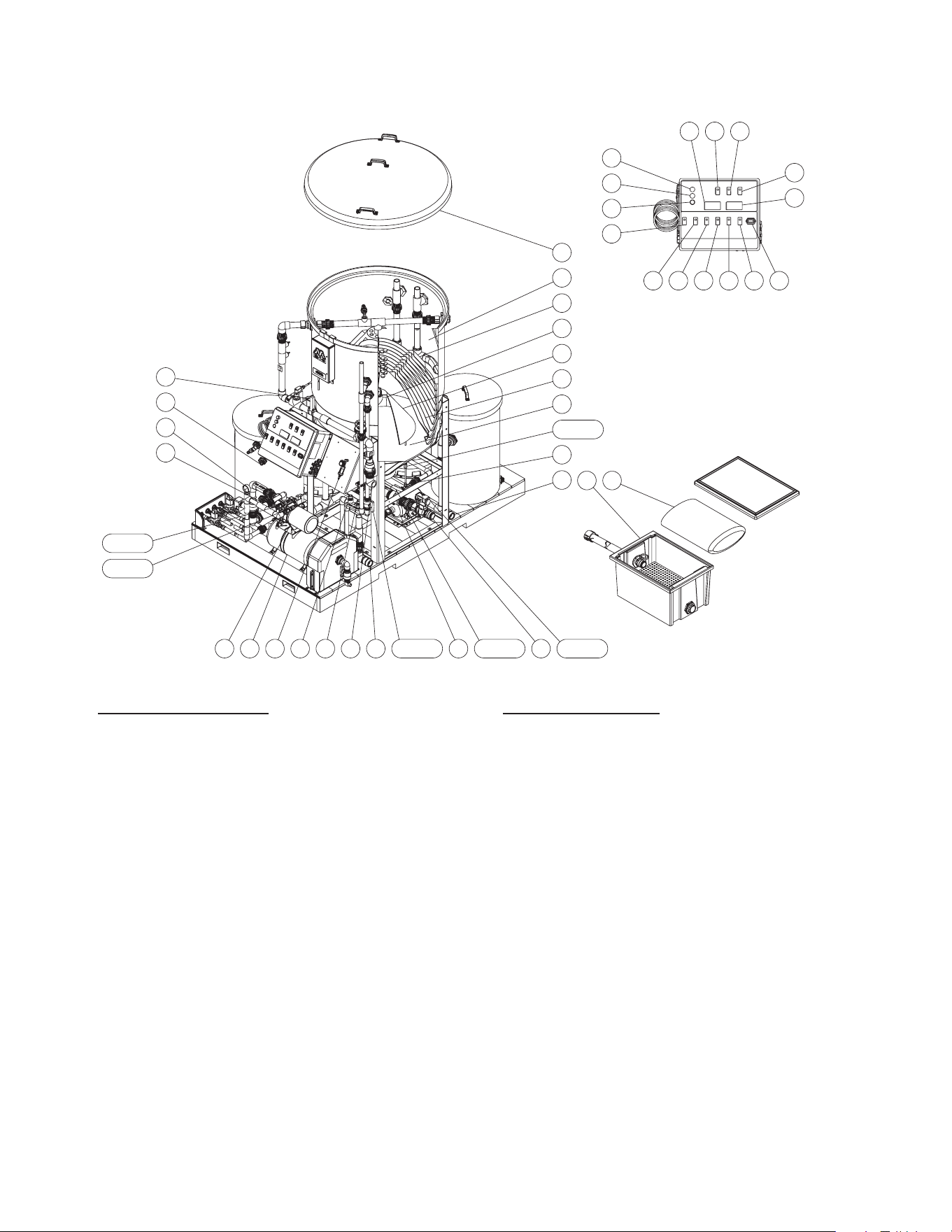
FEATURES FOR WCP-10AB
1
2
4
VALVE 1
VALVE 2
10 11
8 9 VALVE 3 1312
16
17
7
19
20
18
23
VALVE 5VALVE 4
22
21
24
15 14
25
26
27
28
29 30 31 32 33 34
35
36
37
3839
VALVE 6
3
6
5
1. Inlet owmeter
2. High lter pump oat
3. Pressure gauge: transfer pump
4. Transfer pump oat
5. Transfer pump
6. Pressure tank
7. Air system inlet
8. Orp sensor probe
9. pH sensor probe
10. Inlet from sump pump
11. Outlet return to pit
12. Ozone pump
13. Sludge outlet
14. Filter bag
15. Sludge tub
16. Outlet return to pit
17. Ozone injector
18. Solids separation chamber
19. Oil coalescing cones
20. Solids deection cone
21. Diverter tee
22. Top separator cone
23. Oil separation chamber
24. Lid
25. Power indicator light
26. Indicator light: backwashing
27. Start backwash switch
28. Sump pump switch (on/o)
29. Filter pump switch (on/o)
30. Transfer pump switch (on/o)
31. Ph/orp meters switch (on/o)
32. pH pump switch (on/o)
33. Orp pump switch (on/o)
34. Hour meter
35. Orp meter
36. Ozone pump/generator
37. Auto-backwash controller (auto/
manual)
38. Claier drain valve (open/close)
39. Ph meter
UNIT DESCRIPTIONS
VALVE DESCRIPTIONS
1. Pressurized clean-out (sludge
outlet)
2. Pressurized clean-out (solids
chamber)
3. Ozone pump shut-o
4. Manual solids drain
5. Automatic solids drain
6. Ozone ow control
7. Auto backwash ow control
8. Filter pump ow control
9. Multi-media slide valve
10. Polish lter slide valve
11. Oil decanter shut o valve
12. Main inlet ow control
Mi-T-M
®
WCP Automatic Backwash Series Operator's Manual 11
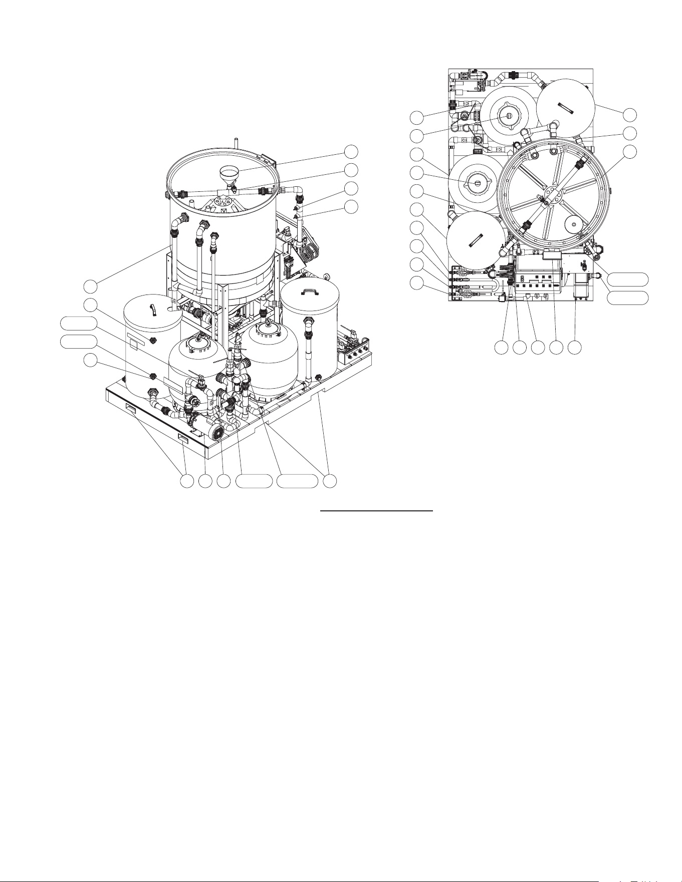
FEATURES FOR WCP-10AB
40
41
VALVE 8
42
43 44
45
46
47
48
49
50
51
52
53
54
56
55
57
58
59
60
63 65
66
67
68
VALVE 12
VALVE 11
VALVE 7
6461 62
VALVE 9
VALVE 10
UNIT DESCRIPTIONS
40. Outlet Y
41. High sump pump oat
42. Low lter pump oat
43. End fork lift holes
44. Filter pump
45. Filter owmeter
46. Side fork lift holes
47. Orp chemical injector
48. Ph chemical injector
49. Anti-siphon device
50. Oil skimmer
51. Multi-media lter
52. Pressure gauge: milti-media lter
53. Polishing lter
54. Pressure gauge: polishing lter
55. Product tank overow
56. Product tank
57. Rain water overow
58. Rinse water oulet
59. Outlet to pressure washer
60. Fresh water inlet
61. pH pump
62. Orp pump
63. Control panel
64. Ozone generator
65. Waste oil decanter
66. Outlet ring
67. Holding tank overow
68. Holding tank
12 Mi-T-M
®
WCP Automatic Backwash Series Operator's Manual
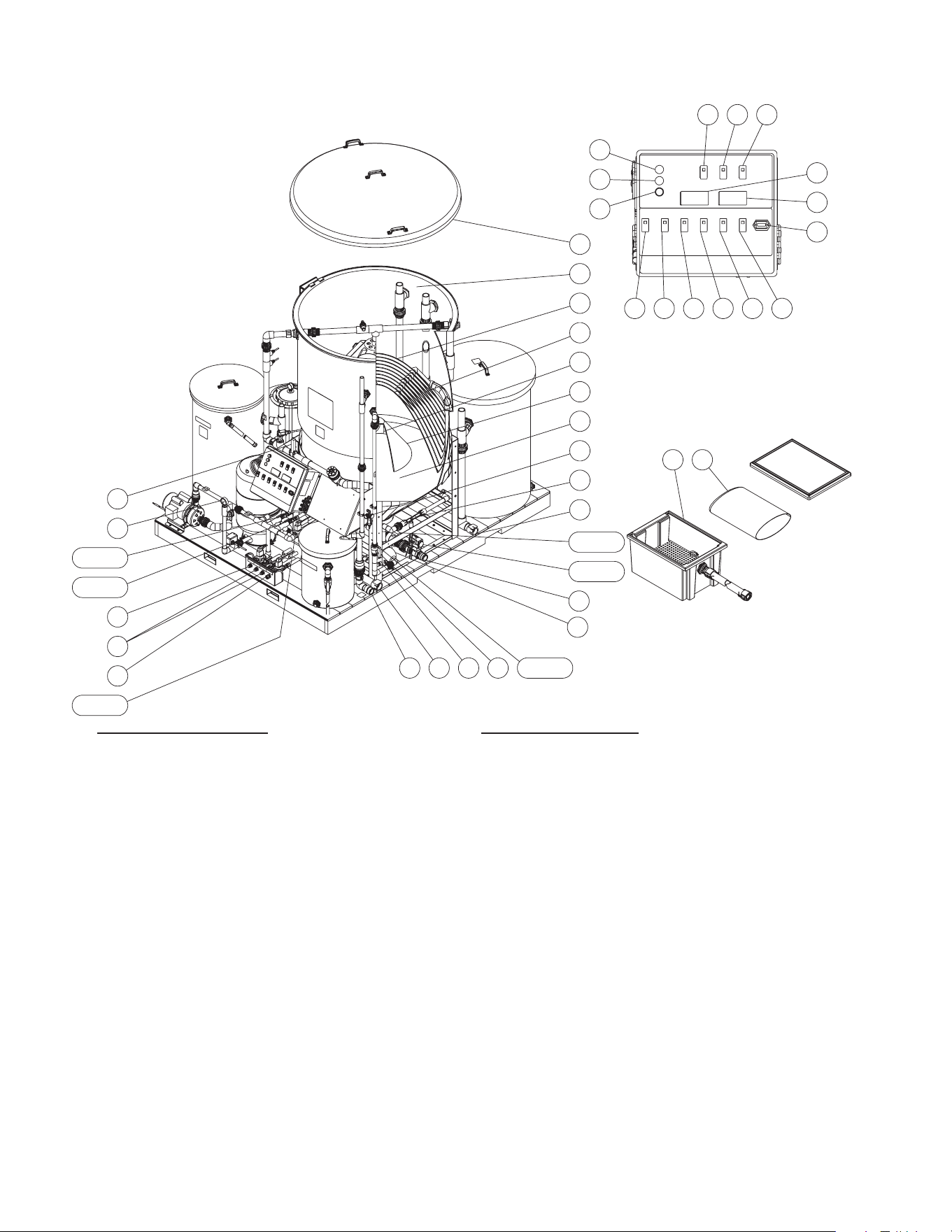
1. Inlet Flowmeter
2. Pressure Gauge: Transfer Pump
3. Rain Water Overow
4. Outlet to Pressure Washer
5. Fresh Water Makeup
6. Inlet From Sump Pump
7. Outlet Return To Pit
8. ORP Sensor Probe
9. pH Sensor Probe
10. Ozone Pump
11. Sludge Outlet
12. Outlet Return To Pit
13. Ozone Injector
14. Air System Inlet
15. Solids Separation Chamber
16. Solids Deection Cone
17. Diverter Tee
18. Oil Coalescing Cones
19. Top Separator Cone
20. Oil Separation Chamber
21. Lid
22. Sludge Tub
23. Filter Bag
24. Power Indicator Light
25. Indicator Light: Backwashing
26. Start Backwash Switch
27. Sump Pump Switch (ON/OFF)
28. Filter Pump Switch (ON/OFF)
29. Transfer Pump Switch (ON/OFF)
30. pH/ORP Meters Switch (ON/OF)
31. pH Pump Switch (ON/OFF)
32. ORP Pump Switch (ON/OFF)
33. Hour Meter
34. ORP Meter
35. pH Meter
36. Ozone Aearation Pump Switch
(ON/OFF)
37. Auto-Backwash Controller
(ON/OFF)
38. Auto-Clarier Drain Valve (ON/
OFF)
UNIT DESCRIPTIONSVALVE DESCRIPTIONS
FEATURES FOR WCP-30AB
1
2
VALVE 1
VALVE 2
3
4
5
VALVE 3
6 7 8 VALVE 4
11
10
9
VALVE 5
12
VALVE 6
13
14
15
16
17
19
20
21
36
37
38
24
25
26
27
28
29 30
31 32
33
34
35
2322
18
1. Pressurized Clean-Out
(Sludge Outlet)
2. Pressurized Clean-Out
(Solids Chamber)
3. Auto Recirculation Solenoid
4. Ozone Flow Control
5. Automatic Solids Drain
6. Manual Solids Drain
7. Auto Backwash Solenoid
8. Filter Flow Control
9. Multi-Media Slide Valve
10. Polish Filter Slide Valve
11. Oil Decanter Shut O Valve
12. Main Inlet Flow Control
Mi-T-M
®
WCP Automatic Backwash Series Operator's Manual 13
39
40
41
VALVE 7
42
VALVE 8
43 VALVE 9 44
45
VALVE 10 46 47
52
51
50
49
48
68
67
66
65
VALVE 12
VALVE 11
64636261
60
59
58
57
56
55
54
41
53
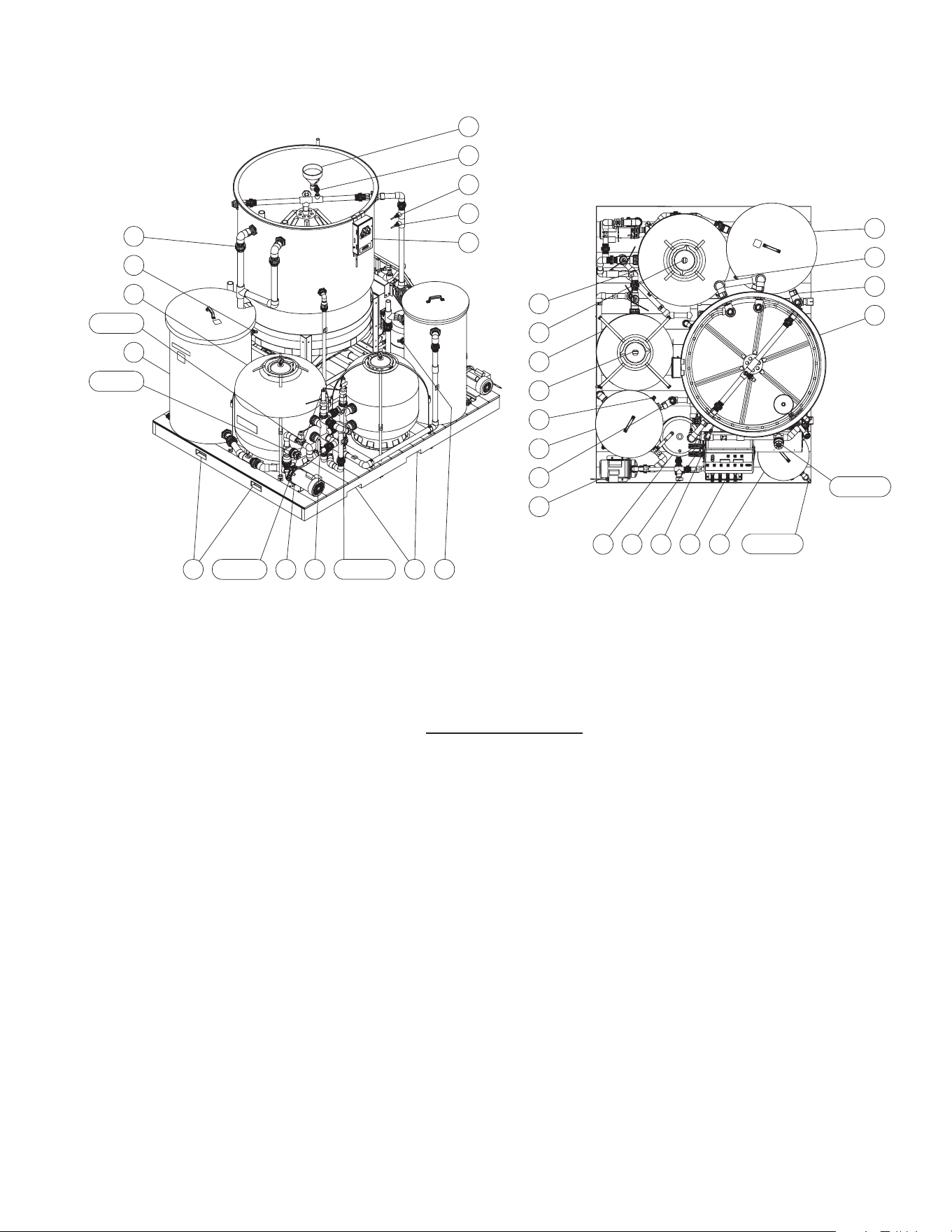
UNIT DESCRIPTIONS
39. Outlet Y
40. High Sump Pump Float
41. Multi-Media Filter
42. Holding Tank
43. End Fork Lift Holes
44. Filter Pump
45. Filter Flowmeter
46. Side Fork Lift Holes
47. High Filter Pump Float
48. Ozone Generator
49. ORP Chemical Injector
50. pH Chemical Injector
51. Anti-Siphon Device
52. Oil Skimmer
53. Pressure Gauge: Multi-Media Filter
54. Polishing Filter
55. Pressure Gauge: Polishing Filter
56. Transfer Pump Float
57. Product Tank
58. Product Tank Overow
59. Transfer Pump
60. Pressure Tank
61. pH Pump
62. ORP Pump
63. Control Panel
64. Waste Oil Decanter
65. Outlet Ring
66. Holding Tank Overow
67. Low Filter Pump Float (Not Visible)
68. Holding Tank
FEATURES FOR WCP-30AB
14 Mi-T-M
®
WCP Automatic Backwash Series Operator's Manual
NOTE: Proper Attire is essential to your safety. It is advised to utilize whatever means necessary to protect eyes, ears,
and skin.
1. A Collection Pit System must already be an established structure before installing the WCP-Series water recycling
treatment system. A well designed pit system is critical for the proper operation of the recycle system. Consult your
Mi-T-M dealer for installation requirements.
2. Place the water recycling treatment system platform on a hard, level surface in an area free of ammable vapors,
combustible dust, gases or other combustible materials.
3. Set the unit so you have access to all four sides.
4. Do not place unit in an area:
a. with insucient ventilation.
b. where environmental hazards (i.e. rain and snow) can come in contact with the water recycling treatment
system.
c. where the unit may freeze.
5. The water recycling treatment system is shipped with some union connections loosened to protect the unit from
shipping damage. Tighten all union connections at this time.
INSTALLATION
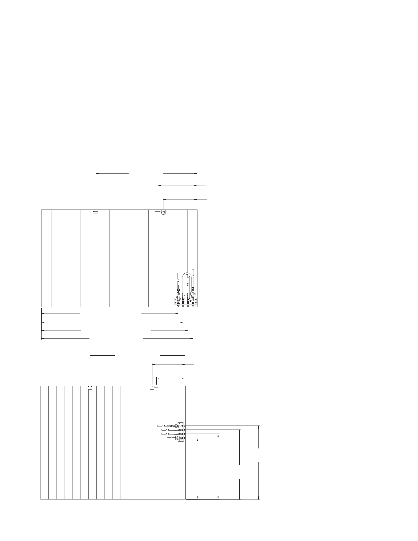
INLET_ OULET LOCATION-WCP-10AB-120313-MLKINLET_ OULET LOCATION-WCP-30AB-031417 MLK
21 5/16
INLET FROM
SUMP PIT
24 1/2
OUTLET RETURN
TO PIT
71
OUTLET RETURN TO PIT
45 7/16
RAINWATER
OVERFLOW
48 7/16
PRESSURE
WATER OUTLET
51 7/16
PRESSURE
WATER OUTLET
54 3/8
FRESH WATER
OUTLET
20 7/8
INLET FROM
SUMP PIT
21”
OUTLET RETURN
TO PIT
62 1/2
OUTLET RETURN
TO PIT
84 7/16 RAINWATER OVERFLOW
87 7/16 RINSE WATER OUTLET
90 7/16 PRESSURE WASHER OUTLET
93 1/2 FRESH WATER INLET
WCP-10AB
WCP-30AB
Mi-T-M
®
WCP Automatic Backwash Series Operator's Manual 15
INSTALLATION
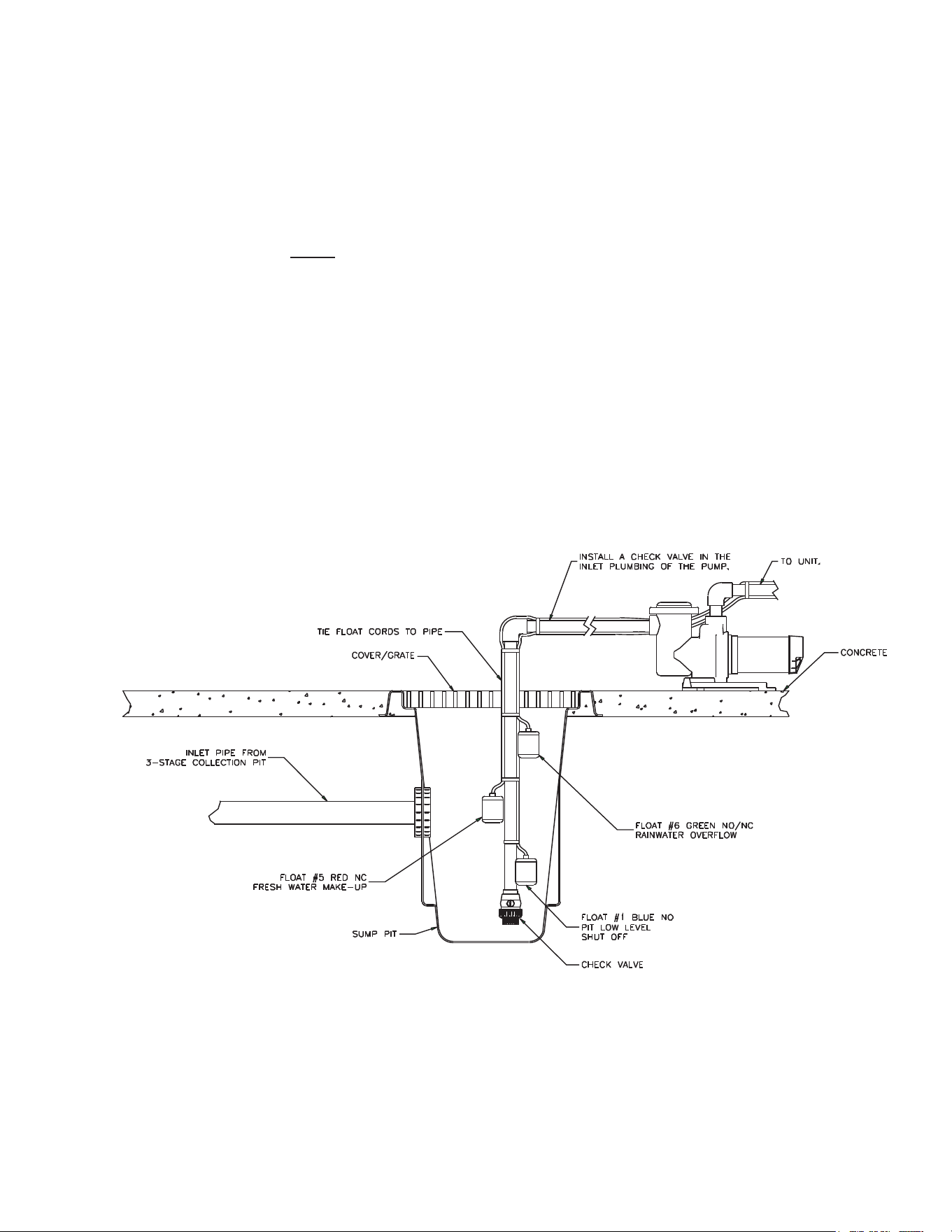
6. Use schedule 80 PVC slip connections.
a. Install the Sump Pump in the plumbing in between the Sump Pit and the unit. Install the Sump Pump close
to the Sump Pit to reduce priming time.
b. Install plumbing from the Sump Pit to the Sump Pump using minimum connection sizes of 2".
c. Install a check valve in the Sump Pit.
d. Install plumbing from the Sump Pump to the unit using 1-1/2" minimum plumbing.
e. Install plumbing from BOTH Outlet Return To Pit lines to the Wash Water Catch Pit using a minimum pipe
size of 3".
f. Install plumbing from the Sludge Tub to the Wash Water Catch Pit. Position the Sludge Tub so that the Sludge
Hose can be connected from the Sludge Outlet to the Sludge Tub.
7. Install the three oats in the Sump Pit. Allow a 2" tether and enough room for them to move freely without interfering
with the plumbing.
a. Float #1 Blue: Pit low level shut-o. Attach this oat 10" above the inlet.
b. Float #5 Red: Fresh water makeup. Height of this oat must be adjusted to the individual pit system.
c. Float #6 Green: Rain water overow. Height of this oat must be adjusted to the individual pit system.
NOTE: The above information is for reference only. Professional installers or architects may use this guideline to meet
specic site requirements.
SUMP PUMP-071101-KS
16 Mi-T-M
®
WCP Automatic Backwash Series Operator's Manual
9. Make the following hose connections:
a. From a pressurized water supply to the Fresh Water Makeup.
b. From the Outlet to Pressure Washer to the pressure washer.
c. From the Rain Water Overow to a storage tank for further processing or disposal. DO NOT SEND THIS
WATER BACK TO THE WASH WATER CATCH PIT!
d. Connect the Sludge Hose to the Sludge Outlet and the Sludge Tub.
e. From a pressurized air supply to the Air System Inlet, turn regulator until gauge reads 60PSI.
NOTE: In most cases, you must have a permit to legally dispose discharged water.
INSTALLATION
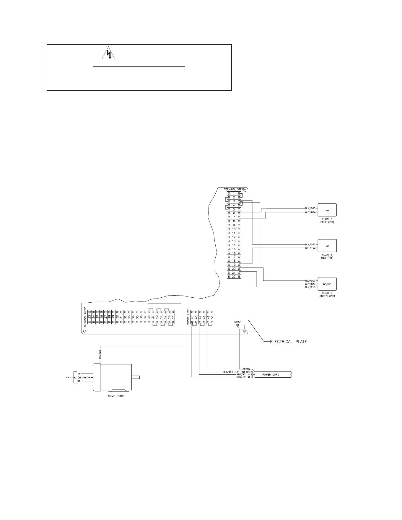
8. A qualied electrician must hook up the electrical system.
a. Verify the electrical supply at the power source is o.
b. Be certain all switches on the Control Panel are in the "OFF" position.
c. Run water tight conduit or cord from the Sump Pump and Floats to the Control
Panel.
d. Run water tight conduit from the local disconnect to the Control Panel.
e. The electrician will need to drill holes in the Control Panel for the conduit and/or
cord(s).
f. Make connections to the terminal strips as shown below.
FIELD WIRING DIAGRAM WCP-30AB-0M10 070218 MLK
WARNING
RISK OF ELECTROCUTION!
TO REDUCE THE RISK OF ELECTROCUTION,
KEEP ALL CONNECTIONS DRY AND OFF THE GROUND.

Mi-T-M
®
WCP Automatic Backwash Series Operator's Manual 17
Before proceeding, answer all the questions on this checklist. YES NO
CODES:
1. Does the electrical wiring meet all codes?
2. Does plumbing meet all codes?
LOCATION:
1. Is the unit located on a hard level surface free of ammable vapors,
combustible dust, gases or other combustible materials?
2. Is the unit located in a large ventilated area?
ELECTRICAL:
1. Is the unit properly grounded?
2. Does the power supply, voltage and amperage match the data plate?
PLUMBING:
1. Is the plumbing sized correctly?
2. Is the check valve installed before the Sump Pump?
3. Are all plumbing connections secured?
4. Are all hose connections secured?
GENERAL:
1. Have all operators using this unit read and understood this entire manual?
2. Has the unit been installed by qualied service people who followed the
instructions listed in this manual?
NOTE: IF "NO" WAS MARKED TO ANY OF THESE QUESTIONS, CORRECT THE SITUATION BEFORE OPERATING.
PRE-OPERATION CHECKLIST
STOP
TO ENSURE YOUR WATER RECYCLE TREATMENT SYSTEM OPERATES SAFELY AND
EFFICIENTLY, COMPLETE THE PRE-OPERATION CHECKLIST BEFORE PROCEEDING.

18 Mi-T-M
®
WCP Automatic Backwash Series Operator's Manual
PREPARATION
PRESTART PROCEDURES:
1. Position the valves on the WCP water recycling treatment system in the "Start-up Mode".
-Water Inlet Flow Control Valve: Turn valve one rotation short of completely closed.
-Filter Control Valve: Turn valve one rotation short of completely closed.
-Air Bleed Valves: Turn valves open.
-Oil Release Valve: Turn valve completely closed.
-Ozone Pump Valve: Turn valve open.
-Pressurized Clean-Out Valves: Turn valves completely closed.
2. Be certain all hoses are securely connected.
3. Be certain the incoming air tube to the Ozone Generator is not obstructed.
4. Be certain all switches on the Control Panel and Ozone Generator are in the "OFF" position.
5. Turn on the power supply. The Power Indicator Light should glow.
START-UP:
1. Ensure water supply to the Fresh Water Makeup is turned on and pit is lled with water. If the pit is not full, water
will ll the Product Tank and overow through the Product Tank Overow and back to the Sump Pit.
2. To prime the Sump Pump, remove the lid over the Basket Strainer and ll the Basket Strainer and the plumbing
from Sump Pit to the Sump Pump with water, then replace the lid.
3. Turn on the Sump Pump Switch; water will ow into the Clarier Tank.
4. Flow can be increased by opening the Water Inlet Flow Control Valve and reading the Inlet Flowmeter. Fill the
Clarier Tank.
5. After the water lls the Solids Separation Chamber, it will begin to ow through the Top Separator Cone and ll
the Oil Separation Chamber.
6. As water lls the Oil Separation Chamber, the Ozone Pump will prime.
7. When the Oil Separation Chamber is full, the water will begin to ow through the Outlet Ring and into the
Outlet Y.
8. The Outlet Y directs the water into the Holding Tank where it is ready to be processed.
9. As the water lls the Holding Tank, it will begin to ow out the Overow Drain at the top of the tank. At this point,
ow can be adjusted with the Water Inlet Flow Control Valve. Set the ow rate to 30GPM. If the oat rises and turns
o the Sump Pump, reduce the ow rate with the Water Inlet Flow Control Valve.
10. Ensure that the Ozone Pump Valve is open and turn on the Ozone System Switch located on the main control
panel. The ozone system is working properly when air bubbles are seen in the Oil Separation Chamber. If no air
bubbles are observed, turn o the Ozone System Switch and loosen the union after the Ozone Pump until the
pump is primed. (The Ozone Flow Control Valve is set at the factory and should not need adjusting.) The Ozone
Generator Switch can now be turned on.
11. Turn on the Filter Pump Switch. The Filter Pump will automatically turn o when the Product Tank is full of
water.
12. As water ows to the lters, use the Filter Control Valve to adjust the water ow to the 30GPM. Check the Filter
Flowmeter located ahead of the Multi-Media Filter.
13. Water will begin to ow from the Multi-Media Filter to the Polishing Filter. As water ows through the Multi-Media
Filter, air will automatically bleed from the Multi-Media Filter to the Polishing Filter.
14. As water ows through the Polishing Filter, air will also automatically bleed from the Polishing Filter to the Product
Tank. Air can also bleed from both lters by opening the Air Bleed Valve on each lter.
NOTE: DO NOT attempt to backwash the lters until all of the air is bled from the system.
15. When the Product Tank is full and the Filter Pump turns o, prime the Transfer Pump by opening the Outlet to
Pressure Washer valve until water exits.
16. Turn on the Transfer Pump Switch to allow water to ow into the Pressure Tank. The Transfer Pump will run until
the pressure system reaches 50PSI. This can take up to 7 minutes.
17. Water is now completely cycled in the system.
Mi-T-M
®
WCP Automatic Backwash Series Operator's Manual 19
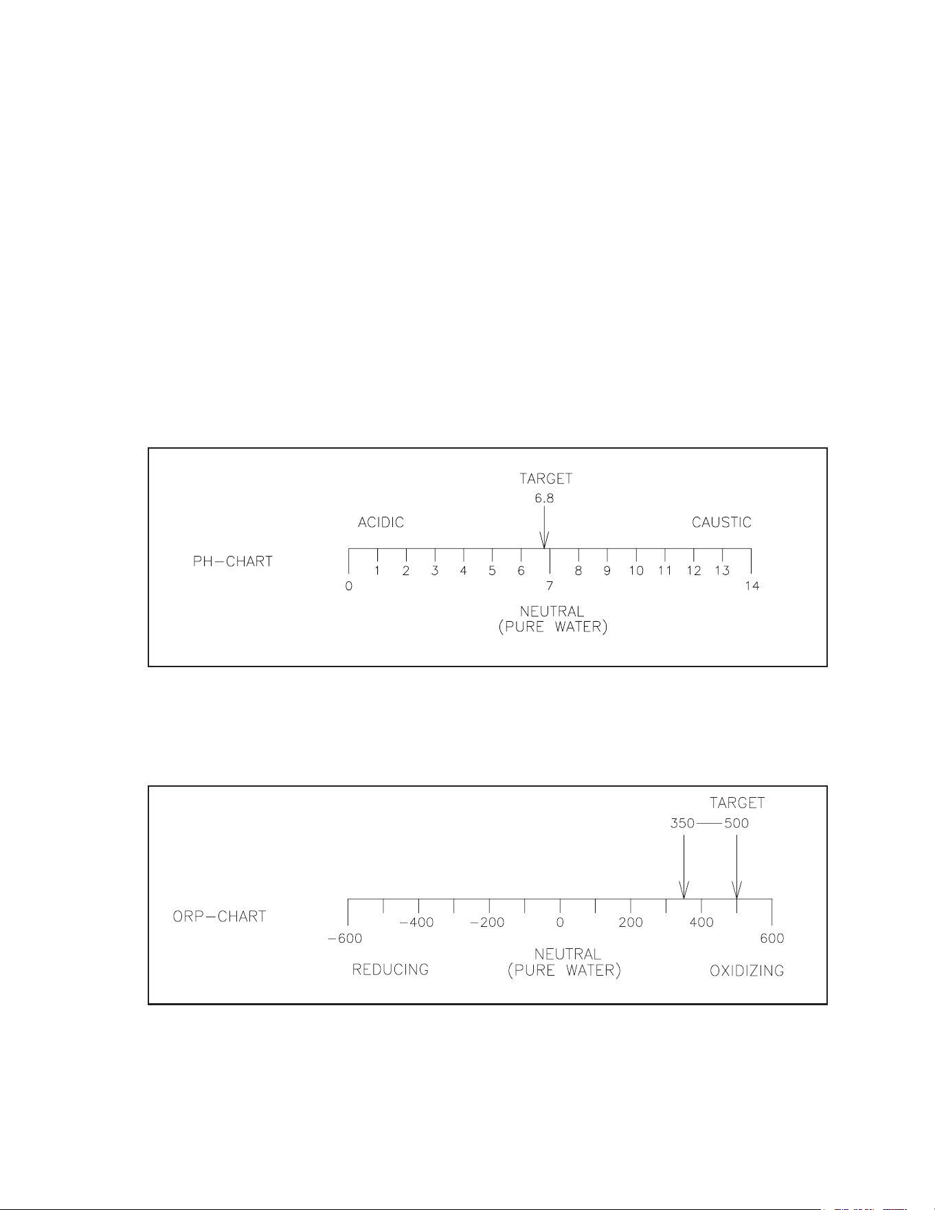
pH AND ORP CONTROL SYSTEM:
Proper pH and ORP levels must be maintained in the pit to prevent growth of bacteria, algae, odors, etc. Water must be
chemically balanced to eectively recycle. The eectiveness of the OPR agent in the water depends on the pH level.
-The optimum pH level to add the OPR agent is 6.5 - 6.8.
-As the pH level rises to 7.5, about 5% more OPR agent must be added to achieve the same ORP reading.
-At a pH level of 8.0 and above, a large amount of OPR agent must be added to increase the ORP reading.
As excess water ows through the Ozone System , it moves past the pH and ORP Sensor Probes before returning
to the Oil Separation Chamber . The Sensor Probes analyze the pH and ORP levels in the water.
a. pH Sensor Probe. This probe analyzes the pH (acidity & alkalinity) in the water. If the water is too acidic (low
pH) the acid will breakdown the iron present in the water to a liquid form, thus causing rusty looking water in the
system. If the water is too alkaline (high pH) the bacteria killing potential of the ORP agent will be drastically
lowered.
b. ORP Sensor Probe. This probe analyzes the Oxidation Reduction Potential (ORP). This reading states amount
of bacteria killing agent in the water.
The probes analyze the pH and ORP levels of the water and display the readings on the digital pH and ORP Meters.
WLP-0009 052617 MLK
WLP-0008-112098-JJ
PREPARATION
20 Mi-T-M
®
WCP Automatic Backwash Series Operator's Manual
PREPARATION
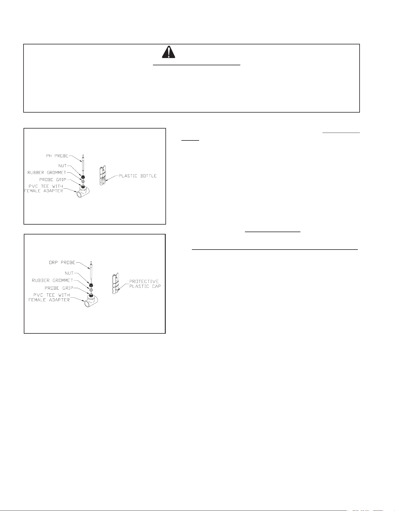
INSTALLATION OF pH AND ORP PROBES:
1. Turn o the Ozone System Switch and close the Ozone Pump
Valve.
2. Locate the probe grips in the Ozone System plumbing and
unscrew the nut from one of the grips.
3. Remove one of the probes (pH or ORP) from its storage
container. (Be certain to save the container for probe storage
during winterizing.)
4. Carefully slide the probe grip nut over the glass probe.
5. Gently push the probe through the probe grip approximately 2
inches and tighten the nut onto the probe grip.
6. Repeat process for the remaining probe.
7. Immediately open the Ozone Pump Valve to rell the plumbing
with water.
THE PROBES CANNOT BE ALLOWED TO DRY OUT.
8. Turn on the Ozone System Switch.
9. Turn on the pH/ORP Meters Switch.
CAUTION
RISK OF PROBE DAMAGE!
-DO NOT ALLOW PROBES TO BE EXPOSED TO AIR. ONCE PROBES ARE IN PLACE, TURN WATER ON
IMMEDIATELY.
-HANDLE PROBES CAREFULLY AS THEY ARE MADE OF GLASS.
-DO NOT ALLOW PROBES TO BE EXPOSED TO FREEZING ENVIRONMENTS. KEEP THE ORIGINAL
CONTAINERS IN WHICH THE PROBES WERE SHIPPED. THEY WILL BE NEEDED FOR PROBE STORAGE
DURING WINTERIZING.
ORP SENSOR PROBE
pH SENSOR PROBE
WLP-0006-110298-JJWLP-0007-112098-JJ
Mi-T-M
®
WCP Automatic Backwash Series Operator's Manual 21
PREPARATION
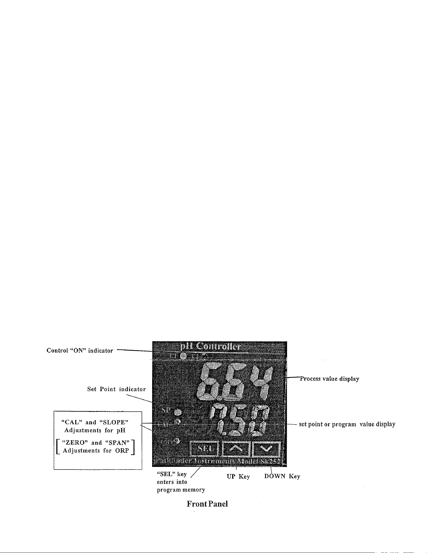
PH CONTROLLER PROGRAMMING
pH controller will come programmed and on measure mode with the following parameters set.
Measure Mode: pH
• Temperature Compensation: 03 MAN (No use of a temperature probe, manually can adjust temperature but
this is normally is not required as long as temperature is in the 60°F-80° it has a small eect on pH reading.)
• Manual temperature set at 70°F.
• 7.00 Buer and 4.01 Buer: Controller is calibrated on STAND using a 7 pH buer solution or calibrator, then
a 4.00 buer calibrator for SLOPE. This will never need to be changed.
• pH relay 1 selected for HI1: Relay 1 will be closed if the probe reads HIGH over the set point (+ 1/2) the
hysteresis. This relay will turn on the chemical pump, low pH chemical to be used to lower pH. Relay 1 can be
changed to LOW1 to work in the opposite direction; if probe reads below set point the chemical pump will turn
on to add high pH chemical.
• Set point 1 is 7.00: pH point at which (+,-) half the hysteresis, the relays will close to turn on chemical pump.
• Hysteresis is at 0.20: The range around the set point that the relays will turn on and o. At a set point of 7.00,
the relay will close between 7.10 and 6.90.
• Set point 2, Relay 2 and Hysteresis 2 is not used for pH controller.
For ORP controllers will come programmed and on measure mode with the following parameters set.
ORP CONTROLLER PROGRAMMING:
ORP controllers will come programmed and on measure mode with the following parameters set.
MEASURE MODE: ORP RMV
• Temperature Compensation: 03 MAN (No use of a temperature probe) does not aect ORP reading.
• Manual temperature set at 70°F.
• 7.00 Buer and 4.01 Buer: Controller is calibrated on STAND using a 7 pH buer solution or calibrator, then a
4.00 buer calibrator for SLOPE. This will never need to be changed.
• Relay 1: Set for ORP RMV
• ORP relay 1 selected for LOW1: Relay 1 will be closed if the probe reads LOW under the set point (- ½) the
hysteresis. This relay will turn on the ORP chemical pump.
• Set point 1 is 350rmv: ORP point at which (+,-) half the hysteresis, the relays will close to turn on chemical pump.
• Hysteresis is at P10.0: The range around the set point that the relays will turn on and o. At a set point of 350mv,
the relay will close between 345mv and 355mv.
• Relay 2 is not used for ORP controller.
22 Mi-T-M
®
WCP Automatic Backwash Series Operator's Manual
FRONT PANEL
The front panel consists of a 4-digit LCD display and 4 keys.
1. [ MODE ] key:
1a. In the Measure mode, this key will switch the display in sequence from pH, Temperature, ORP absolute mV,
ORP relative mV and back to pH again.
1b. In the Calibration/Setting mode, pressing this key for three seconds will move you back to the previous pa-
rameter in the case when recalibration / resetting is required.
2. [ UP ] key:
2a. In the Calibration mode, pressing this key will show the next possible option. In the Setting mode, pressing
this key will show the next possible option and increases the numeral increment.
2b. In the Measure mode, pressing this key and [ENTER] key at the same time, the unit will enter the Calibration mode.
3. [ DOWN ] key:
3a. In the Calibration mode, pressing this key will show the next possible option. In the Setting mode, pressing
this key will show the next possible option and decreases the numeral increment.
3b. In the Measure mode, pressing this key and [ENTER] key at the same time, the unit will enter the Setting mode.
4. [ ENTER ] key:
In any mode where the user can change the settings, pressing this key will save the new
settings. If no change has been made then pressing this key will just move the user to the
next setting.
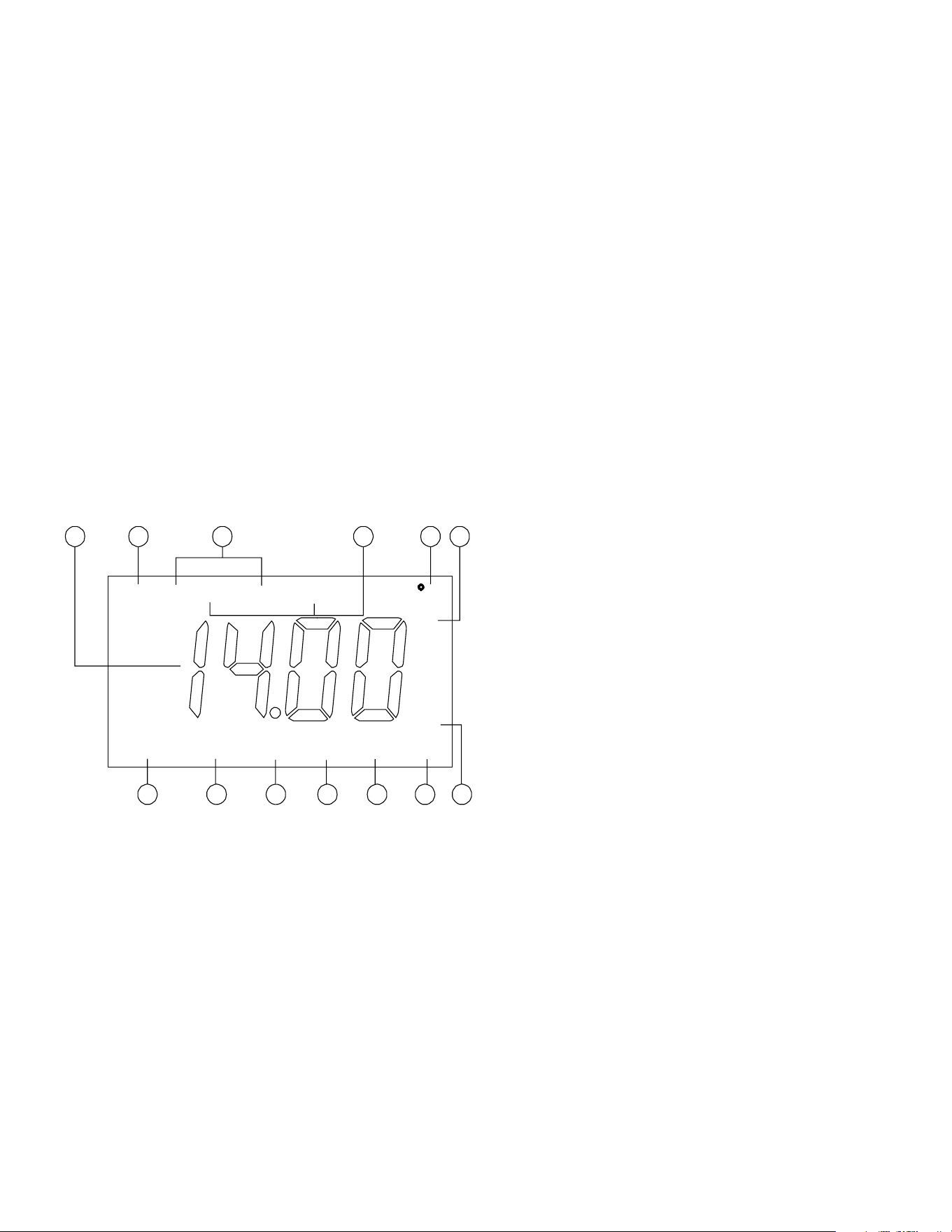
LCD SCREEN
1. Major LCD display.
2. CAL – This icon will be displayed if the meter is in the Calibration/Setting mode.
3. HI1 & LOW1 – These icons, when displayed, indicate relay action and relay number.
4. HI2 & LOW2 –These icons, when displayed, indicate relay action and relay number.
5. °C – Temperature and unit display.
6. pH – Unit indicator.
7. STAND – This icon will blink before Buer 1 calibration. The icon will stay on while Buer 1 is being calibrated.
8. SLOPE – This icon will blink before Buer 2 calibration. The icon will stay on while Buer 2 is being calibrated.
9. 6.86 – The 6.86 buer group: 6.86, 4.00, 9.18.
10. 7.00 – The 7.00 buer group: 7.00, 4.01, 10.01.
11. ATC –This icon will be displayed when a temperature probe is connected.
PREPARATION
HI1 HI2 LOW1 LOW2
STAND
SLOPE
RmV
CAL
6.86 7.00
ATC MAN
pH
654321
13121110987
C
Mi-T-M
®
WCP Automatic Backwash Series Operator's Manual 23
12. MAN –This icon will be displayed when a temperature probe is not connected.
13. RmV – Unit indicator.
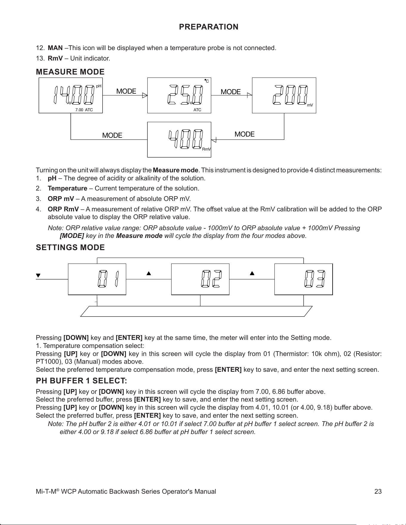
MEASURE MODE
Turning on the unit will always display the Measure mode. This instrument is designed to provide 4 distinct measurements:
1. pH – The degree of acidity or alkalinity of the solution.
2. Temperature – Current temperature of the solution.
3. ORP mV – A measurement of absolute ORP mV.
4. ORP RmV – A measurement of relative ORP mV. The oset value at the RmV calibration will be added to the ORP
absolute value to display the ORP relative value.
Note: ORP relative value range: ORP absolute value - 1000mV to ORP absolute value + 1000mV Pressing
[MODE] key in the Measure mode will cycle the display from the four modes above.
SETTINGS MODE
Pressing [DOWN] key and [ENTER] key at the same time, the meter will enter into the Setting mode.
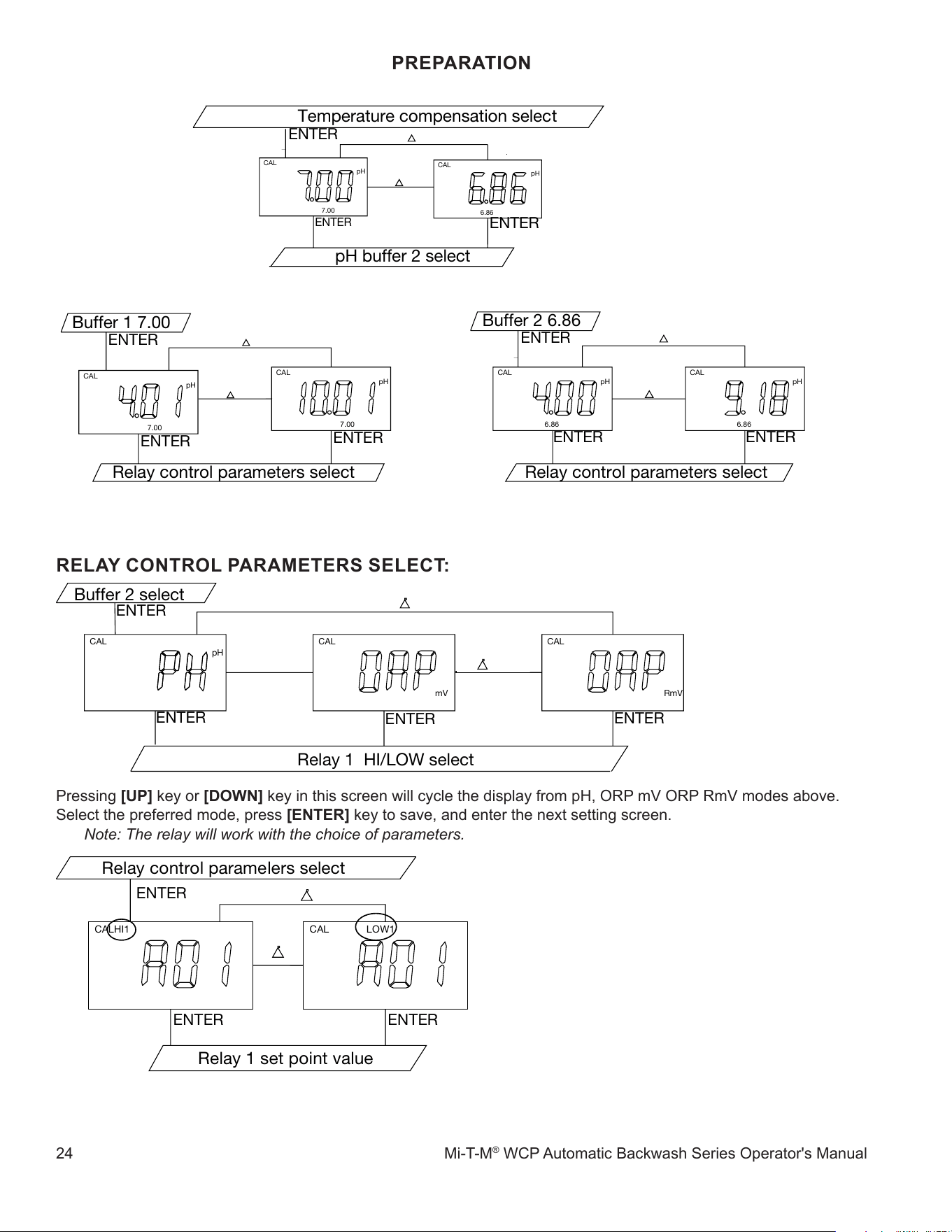
1. Temperature compensation select:
Pressing [UP] key or [DOWN] key in this screen will cycle the display from 01 (Thermistor: 10k ohm), 02 (Resistor:
PT1000), 03 (Manual) modes above.
Select the preferred temperature compensation mode, press [ENTER] key to save, and enter the next setting screen.
PH BUFFER 1 SELECT:
Pressing [UP] key or [DOWN] key in this screen will cycle the display from 7.00, 6.86 buer above.
Select the preferred buer, press [ENTER] key to save, and enter the next setting screen.
Pressing [UP] key or [DOWN] key in this screen will cycle the display from 4.01, 10.01 (or 4.00, 9.18) buer above.
Select the preferred buer, press [ENTER] key to save, and enter the next setting screen.
Note: The pH buer 2 is either 4.01 or 10.01 if select 7.00 buer at pH buer 1 select screen. The pH buer 2 is
either 4.00 or 9.18 if select 6.86 buer at pH buer 1 select screen.
PREPARATION
7. 00
ATC
pH
ATC
C
mV
RmV
MODE
MODE
MODE
MODE
+ENTER
ENTER ENTER
ENTER
pH buffer 1 select
CAL
ATC
CAL
ATC
CAL
MAN
24 Mi-T-M
®
WCP Automatic Backwash Series Operator's Manual
PREPARATION
RELAY CONTROL PARAMETERS SELECT:
Pressing [UP] key or [DOWN] key in this screen will cycle the display from pH, ORP mV ORP RmV modes above.
Select the preferred mode, press [ENTER] key to save, and enter the next setting screen.
Note: The relay will work with the choice of parameters.
Temperature compensation select
pH buffer 2 select
ENTER
ENTER
ENTER
CAL
6.86
pH
CAL
7.00
pH
Buffer 1 7.00
Relay control parameters select
ENTER
CAL
7.00
pH
CAL
7.00
pH
ENTER
ENTER
Buffer 2 6.86
Relay control parameters select
ENTER
ENTER
ENTER
CAL
6.86
pH
CAL
6.86
pH
Buffer 2 select
Relay 1 HI/LOW select
ENTER
ENTER
ENTER
ENTER
RmV
CAL
CAL
pH
mV
CAL
Relay control paramelers select
Relay 1 set point value
ENTER
ENTER
ENTER
HI1CAL CALLOW1
Mi-T-M
®
WCP Automatic Backwash Series Operator's Manual 25
PREPARATION
Pressing [UP] key or [DOWN] key in this screen will cycle the display from HI, LOW modes above. Select the preferred
mode, press [ENTER] key to save, and enter the next setting screen.
Note: See “Controlling the relays ” page.
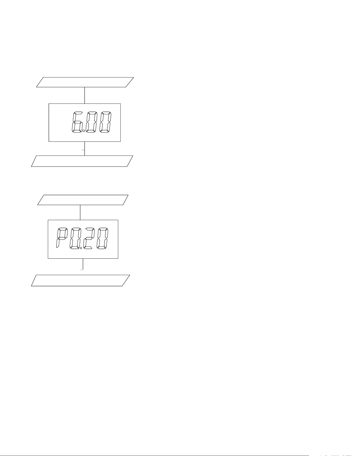
Relay 1 set point value:
Pressing [UP] key or [DOWN] key in this screen to adjust the value, press [ENTER] key to save, and enter the next
setting screen.
Relay 1 hysteresis value:
Pressing [UP] key or [DOWN] key in this screen to adjust the value, press [ENTER] key to save, and enter the next
setting screen.
Relay 2 High / Low select: Same as “Relay 1 work way select”
Relay 2 set point value: Same as “Relay 1 set point value”
Relay 2 hysteresis value: Same as “Relay 1 hysteresis value”
PH CALIBRATION MODE
The TX20 uses 2-point calibration for pH. The rst point must be 6.86/7.00, and the second point can either be 4.00/4.01
or 9.18/ 10.01.
In the pH Measure mode, pressing [UP] key and [ENTER] key at the same time to allow the meter to go to the pH Cal-
ibration mode.
CONTROLLING THE RELAYS
1. ISOLATION VOLTAGE:
The maximum isolation voltage of the relay output contacts is 1500 VDC. The voltage dierential between the relay
output contacts and the load should not exceed 1500 VDC.
2. OUTPUT LOAD:
Relay 1 HI/LOW select
Relay 1 hysteresis value
ENTER
ENTER
CAL
pH
Relay 2 HI/LOW select
ENTER
ENTER
CAL
Relay 1 set point value
pH

26 Mi-T-M
®
WCP Automatic Backwash Series Operator's Manual
PREPARATION
The current through the relay output contacts should not exceed 5 Amp at 115 VAC and 2.5 Amp at 230 VAC in order
not to cause permanent damage to the relay contacts. This rating is specied for resistive loads only.
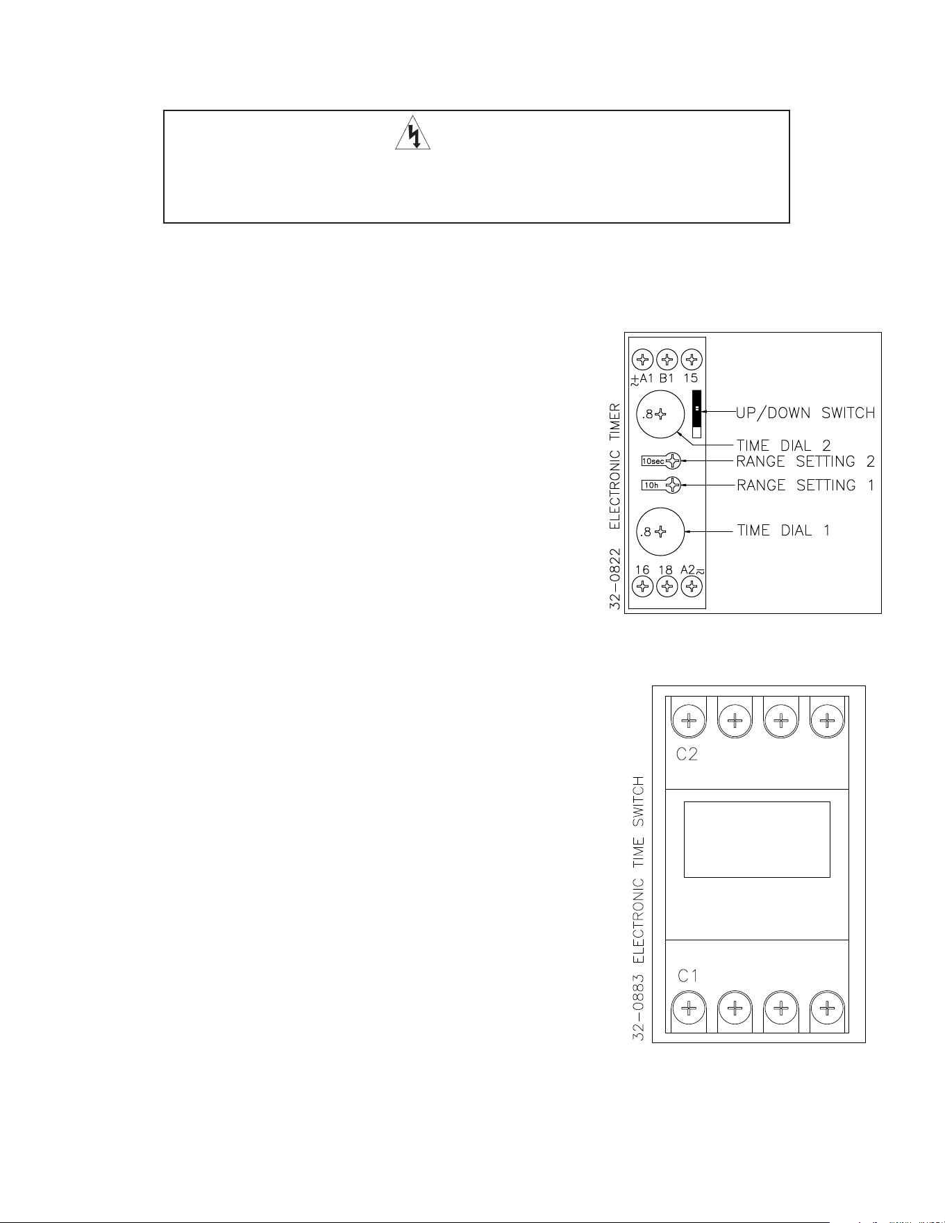
3. RELAY ACTION, RELAY SET POINT AND HYSTERESIS VALUE:
If the relay action is set to HIGH, the relay will turn ON at (Set Point +1/2 Hysteresis ), and will turn OFF at (Set Point
-1/2 Hysteresis ).
If the relay action is set to LOW, the relay will turn ON at (Set Point -1/2 Hysteresis ), and will turn OFF at (Set Point
+1/2 Hysteresis ).
There are two Independent relays the user can bind to the pH, ABSOLUTE mV or RELATIVE mV mode. The user can
only bind the two relays to one reading mode at a time. The user can change this anytime by changing option at the
setting mode.
Note:
1. The ideal set point range for pH is 0.00 to 16.00 pH.
2. The ideal set point range for absolute mV is –2000 to 2000 mV.
3. The ideal set point range of for relative mV is -3000 to 3000 mV.
FINAL pH AND ORP SYSTEM SETUP:
1. Place the hoses from the pH and ORP Pumps into the Adjustment Chemicals.
a. The recommended pH chemical for this system is aluminum sulfate.
b. The recommended ORP chemical for this system is Safe 0
3
.
2. Turn on the pH and ORP Pump Switches. Chemicals will be inserted into the water as necessary.
Relay Action Eective RELAY-ON Set Point Eective RELAY-OFF Set Point
HI S.P. + (1/2 H.V) S.P. – (1/2 H.V)
LOW S.P. – (1/2 H.V) S.P. + (1/2 H.V.)
Mi-T-M
®
WCP Automatic Backwash Series Operator's Manual 27
PREPARATION
SETTING THE TIMERS:
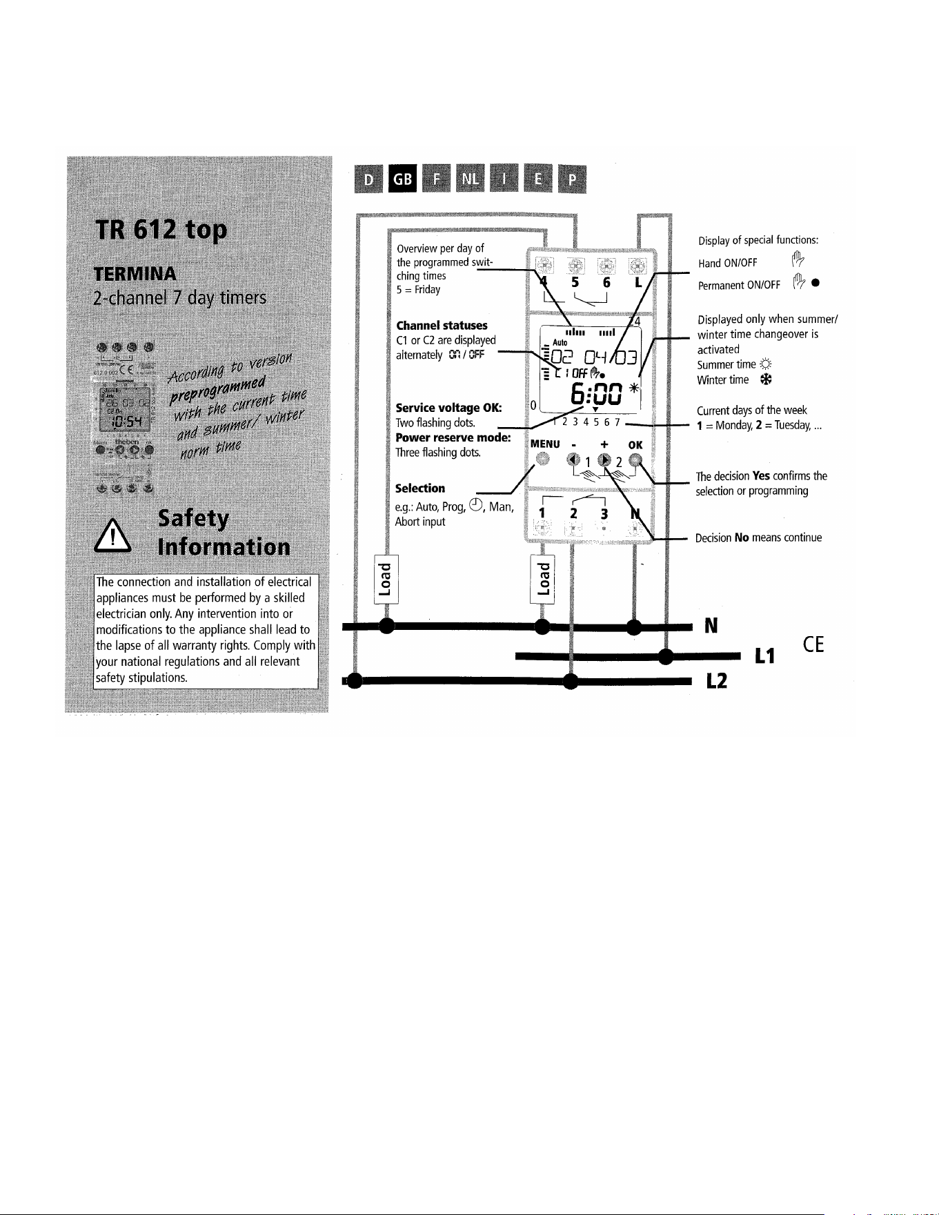
Two timers are located in the main area of the unit control panel. The rst is
an electronic timer used to operate the clarier drain valve. Second is a time
switch used to operate the water recycling system and the auto-backwash
system. These timers have been pre-set at the factory.
ELECTRONIC TIMER:
A simple Phillips head screwdriver can be used to make the adjustment here.
Available settings on both range setting adjustments are:
1 second, 3 seconds, 10 seconds, 1 minute, 3 minutes, 10 minutes, 1 hour,
3 hours, 10 hours, and 60 hours.
The time dials determine the percent value of the range settings from 0 to 1.0.
As an example, if the range setting is at 10 hours, and the corresponding time
dial is at 0.8, then the value for that function is 80% of 10 hours, or 8 hours.
Range setting/ timer dial setting one determines the frequency of the timer
activation. It is set to activate every 8 hours. Range setting/ timer dial setting
two determines the duration of the timer activation. Duration of the dump
cycle is set for 8 seconds. The slide switch should remain in the up position.
TIME SWITCH:
The time switch is used as a dual functioning timer. The rst function (C1)
is set to activate the auto-backwash system once a day at 9 PM. Secondly,
the time switch is used to activate the water recycling system (C2) once a
day at 2 AM. If the water in the recycle system lies dormant for more than
six hours, it tends to become stagnant and odorous. Dependant on use, you
may need to add one or two more daily cycles to this timer program
When setting the time switch, a program must be entered for both the turn on
time and the turn o time. Each on cycle and o cycle count as one program.
There are 42 programs available on this time switch. FOR COMPLETE
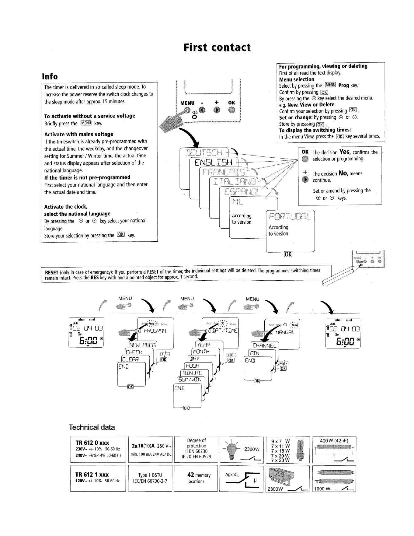
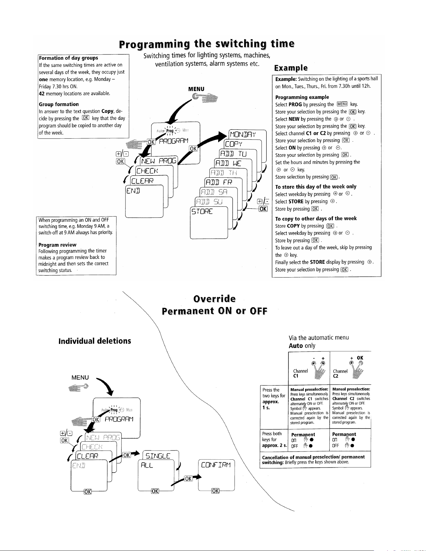
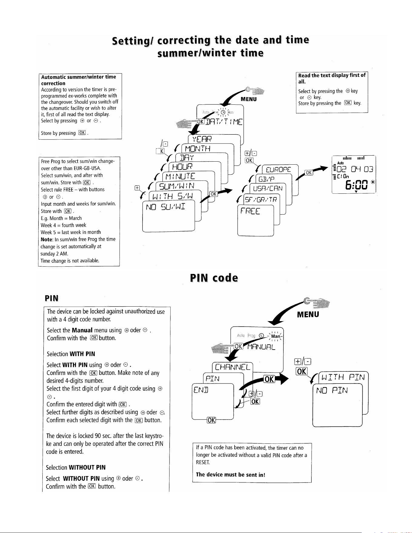
PROGRAMMING INSTRUCTIONS FOR THE TIME SWITCH, PLEASE
REFER TO THE MANUFACTURERS MANUAL on the following pages.
WARNING
RISK OF ELECTROCUTION!
MAKE SURE ALL POWER TO THE UNIT IS TURNED OFF WHEN WORKING ON
COMPONENTS IN THE CONTROL PANEL.
28 Mi-T-M
®
WCP Automatic Backwash Series Operator's Manual
PROGRAMMING INSTRUCTIONS FOR THE TIME SWITCH:
PREPARATION
Mi-T-M
®
WCP Automatic Backwash Series Operator's Manual 29
PREPARATION
30 Mi-T-M
®
WCP Automatic Backwash Series Operator's Manual
PREPARATION
Mi-T-M
®
WCP Automatic Backwash Series Operator's Manual 31
PREPARATION

32 Mi-T-M
®
WCP Automatic Backwash Series Operator's Manual
1. The water recycling treatment system is now ready to operate.
2. Ensure the switches on the Control Panel are in the following position:
Clarier Drain Valve Auto-Backwash Controller Ozone / Aeration Pump Ozone Generator
OFF ON ON ON
Sump Pump Filter Pump Transfer Pump pH/ORP Meters pH Pump ORP Pump
ON ON ON ON ON ON
3. With the sump pump running, use Water Inlet Flow Control Valve to make sure the Inlet Flowmeter reads at least
10/30 GPM, depending on the unit.
4. Oil Skimmer positioning must be done when water is owing into the Clarier Tank at the rated ow rate.
a. Tilt the Oil Skimmer so that it just breaks the surface of the water.
b. When a thick layer of oil accumulates in the Waste Oil Decanter, place a container below Waste Oil Release
Valve and open the valve until water begins to come out.
5. Monitor the system closely the rst few days to ensure smooth operation.
OPERATION
Mi-T-M
®
WCP Automatic Backwash Series Operator's Manual 33
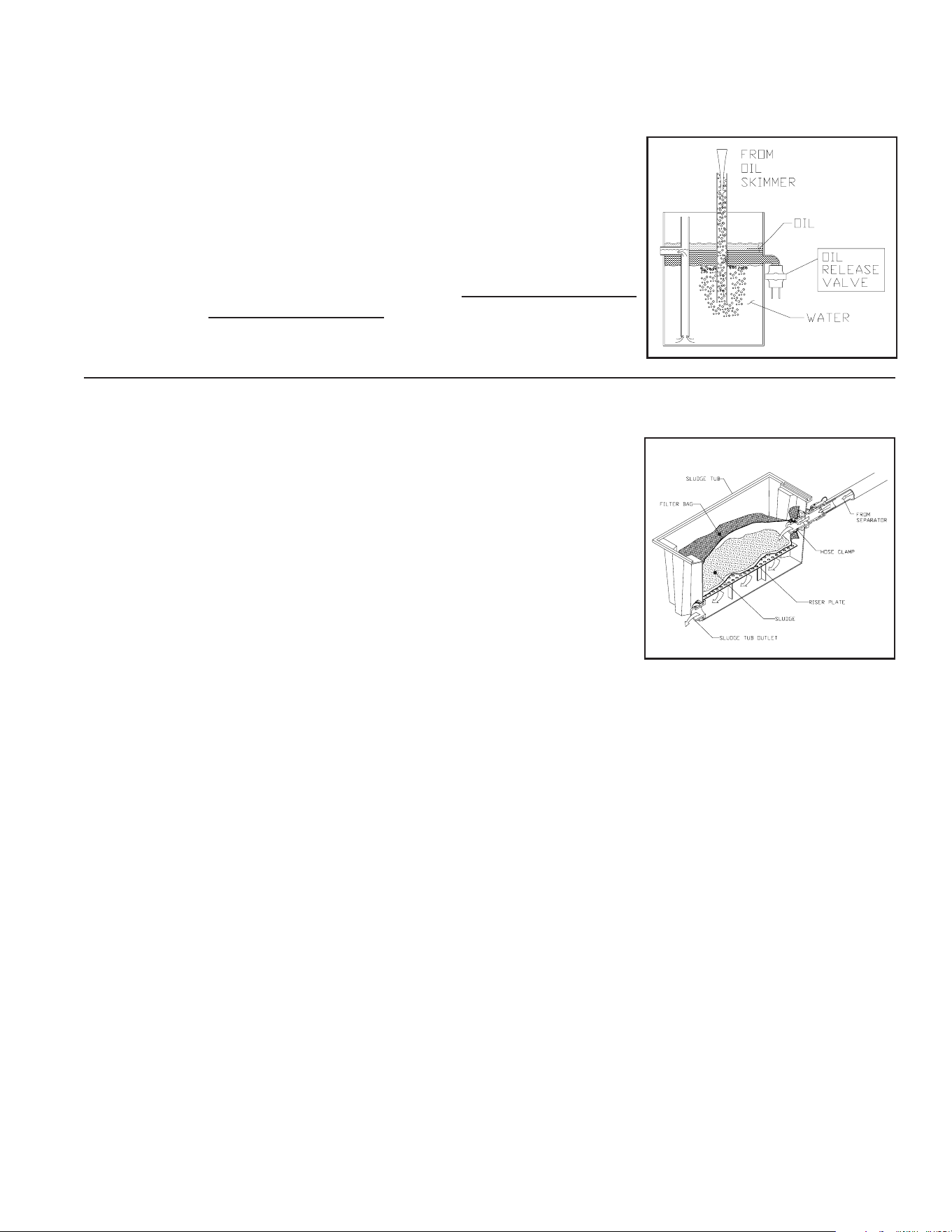
WASTE OIL DECANTER:
1. The Oil Skimmer removes the top layer of oil and water from the Oil Separation
Chamber and sends it to the Waste Oil Decanter.
2. As the Waste Oil Decanter lls with the oil/water mixture, the oil will oat to
the top while the water remains on the bottom.
3. The water then moves up the standpipe, through the Oil Decanter Outlet,
and back to the Wash Water Catch Pit to be recycled again.
4. As oil accumulates, it will have to periodically be removed from the Waste
Oil Decanter.
a. Place a 5 gallon bucket below the hose on the Waste Oil Release Valve
b. Open the Waste Oil Release Valve and allow oil to ow into the 5 gallon
bucket. Turn o valve when water begins owing into the bucket.
c. Dispose of oil according to EPA Standard
SOLIDS COLLECTION AREA:
The solids collection area of the Solids Separation Chamber will need to be
cleaned occasionally to prevent overow of solids into the Holding Tank.
1. Ensure the Sludge Hose is connected to the Sludge Tub and the Sludge
Outlet Assembly and a Filter Bag is secured in the Sludge Tub.
2. The unit will automatically backwash once for each pin that is pulled out on
the Clarier Drain Valve Timer (See Setting the Timers to adjust).
3. The Clarier Drain Valve can be opened manually by turning the Clarier
Drain Valve Switch to the "ON" position. The valve will remain open until the
switch is turned to the "OFF" position.
4. If the solids accumulated at the bottom of the Solids Separation Chamber
are unable to drain, open Valve 4 and Valve 5 to push the solids towards the
Sludge Tub. If the solids are still unable to drain, open Valve 6 and Valve 7 to
break up the solids on the inside of the Solids Separation Chamber. When
the solids from the Solids Separation Chamber is emptied, close Valve 4,
Valve 5, Valve 6 and Valve 7.
5. As sludge is forced into the disposable Filter Bag, solids in the Sludge are
retained by the disposable Filter Bag and uids drain out into the area created
by the Riser Plate.
6. The remaining water drains out of the bottom of the Sludge Tub through Sludge
Tub Outlet and back to the Wash Water Catch Pit.
7. When the Filter Bag is lled with accumulated solids, loosen the Hose Clamp
used to retain the Filter Bag, tie the Filter Bag o and dispose of in a manner
consistent with local and federal regulations.
8. To replace the Filter Bag, bunch up the neck and feed it through the Hose
Clamp, place the Hose Clamp and Filter Bag over the inside nipple on the
inlet coupling and tighten the Hose Clamp.
MAINTENANCE
WCP-0027030700-WKB
WASTE OIL DECANTER
WCL-0026-030100-WKB
SOLIDS COLLECTION AREA
34 Mi-T-M
®
WCP Automatic Backwash Series Operator's Manual
BACKWASHING OF FILTERS:
The unit will automatically backwash once for each pin that is pulled out on the Automatic Backwash Timer (See Setting
the Timers). If an additional backwash is desired, follow the manual procedures below:
AUTOMATIC BACKWASH SEQUENCE:
1. The power to the unit must be turned on and the Auto-Backwash Controller Switch must be in the “ON”
position.
2. Automatic Backwash Timer turns on at specied time.
3. Backwashing When Lit light turns on.
4. Multimedia Filter Valve moves to backwash position.
5. Filter Pump turns on and runs for 10 minutes.
6. Filter Pump turns o.
7. Multimedia Filter Valve moves to lter position.
8. Polishing Filter Valve moves to backwash position.
9. Filter Pump turns on and runs for 5 minutes.
10. Filter Pump turns o.
11. Polishing Filter Valve moves to lter position.
NOTE: If lter pump is running, backwash sequence will not start until the lter pump turns o.
MANUAL START OF BACKWASH SEQUENCE:
NOTE: This must be done at time when pressure washers will not be in use for 15 minutes.
1. Auto-Backwash Controller Switch MUST be in the "ON" position.
2. Press Start Backwash button.
3. Backwash will continue from #3 of the "Automatic Backwash Sequence".
MAINTENANCE
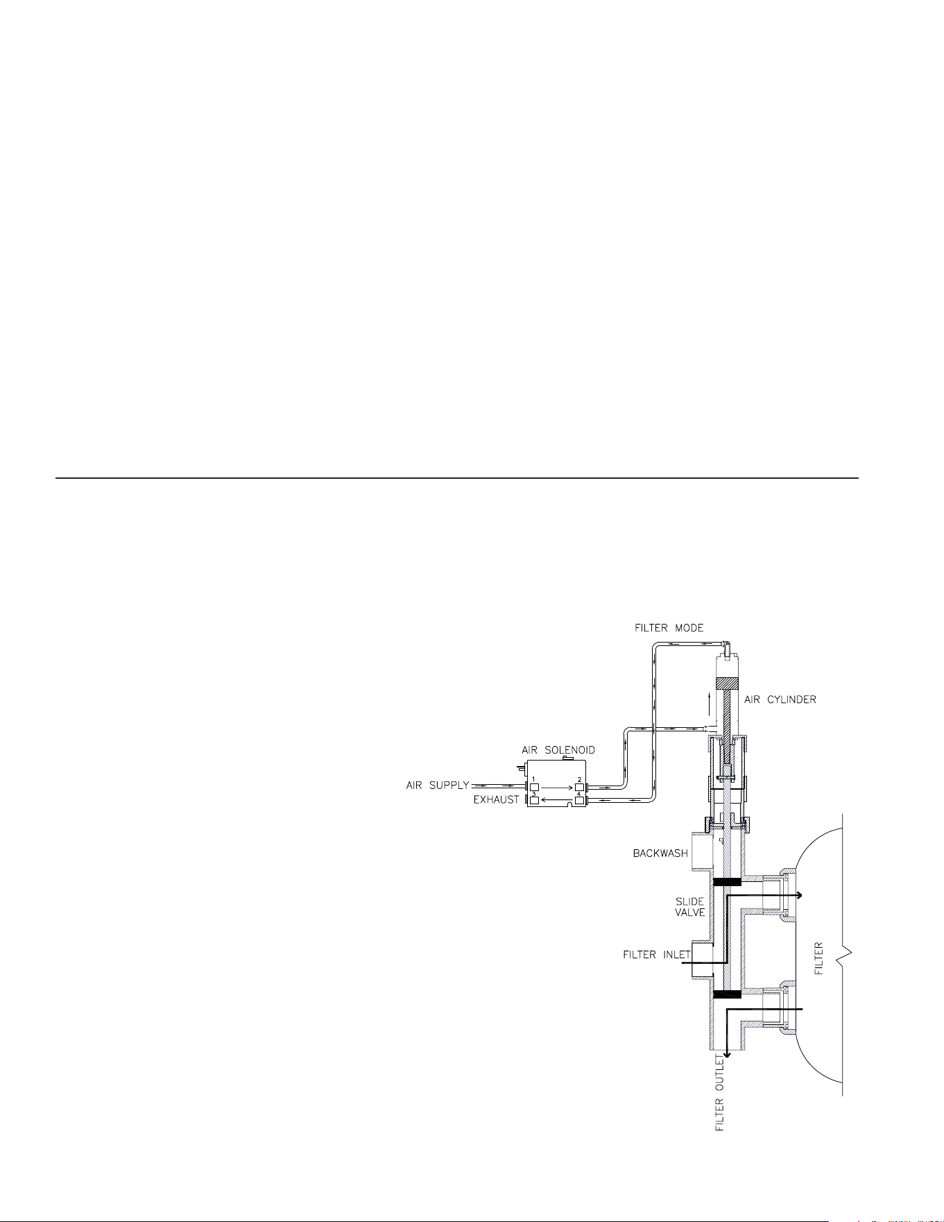
Filter Mode:
In normal operation the slide valve is in lter mode
and in the up position. Compressed air is forced
through the air solenoid and into the bottom of
the slide valve air cylinder. The air pushes the air
cylinder plunger up pulling up the slide valve shaft.
Discs on the slide valve shaft direct the water ow
from the lter inlet to the top of the lter pod. Water
travels through the media to the bottom and out
the lter outlet line.
Mi-T-M
®
WCP Automatic Backwash Series Operator's Manual 35
MAINTENANCE
ACTIVE CARBON TEST:
To ensure the Polishing Filter is working eectively, you should perform an active carbon test.
I. TEST PROCEDURE A: For systems with pH & ORP Control, your test kit will include test strips.
A. Following the directions included with the test strip kit, test the water in the Holding Tank.
1. The test strip should show chlorine present in the system.
2. If no chlorine is present, check the following:
a. The ORP Adjustment Chemical is empty. Replace.
b. The ORP Pump is turned o or malfunctioning. Ensure the ORP Pump Switch is in the ON
position. Contact your local distributor if additional maintenance is needed.
c. If you are not using chlorine as an ORP control, you must refer to TEST PROCEDURE B to ensure the
carbon is still active.
B. With the Filter Pump operating, use a test strip to test the incoming water to the Product Tank.
1. The test should not show chlorine present in the system.
2. If chlorine is present, the carbon must be replaced. See REMOVING AND REFILLING MEDIA section.
II. TEST PROCEDURE B: For systems without pH & ORP Control, your test kit will include a Carbon removal scoop,
4 oz. empty container, 2 oz. empty container, 2 oz. bottle of chlorine, Chlorine test paper with color chart. Contact
your local distributor if any parts are missing.
A. Turn o the Filter Pump Switch.
B. Unscrew the cap and remove the Polishing Filter Valve.
C. Fill the Carbon Removal Scoop with a sample of carbon from the Polishing Filter tank.
D. Add 2 oz. of the carbon sample into the 4 oz. empty container.
E. Fill the 2 oz. empty container with water.
F. To the water, add one drop of chlorine.
G. Follow the directions on the bottle of test strips. Dip a chlorine test paper into the 2 oz. container. The chlorine
reading should be at least 10 parts per million. If not, add another drop of chlorine.
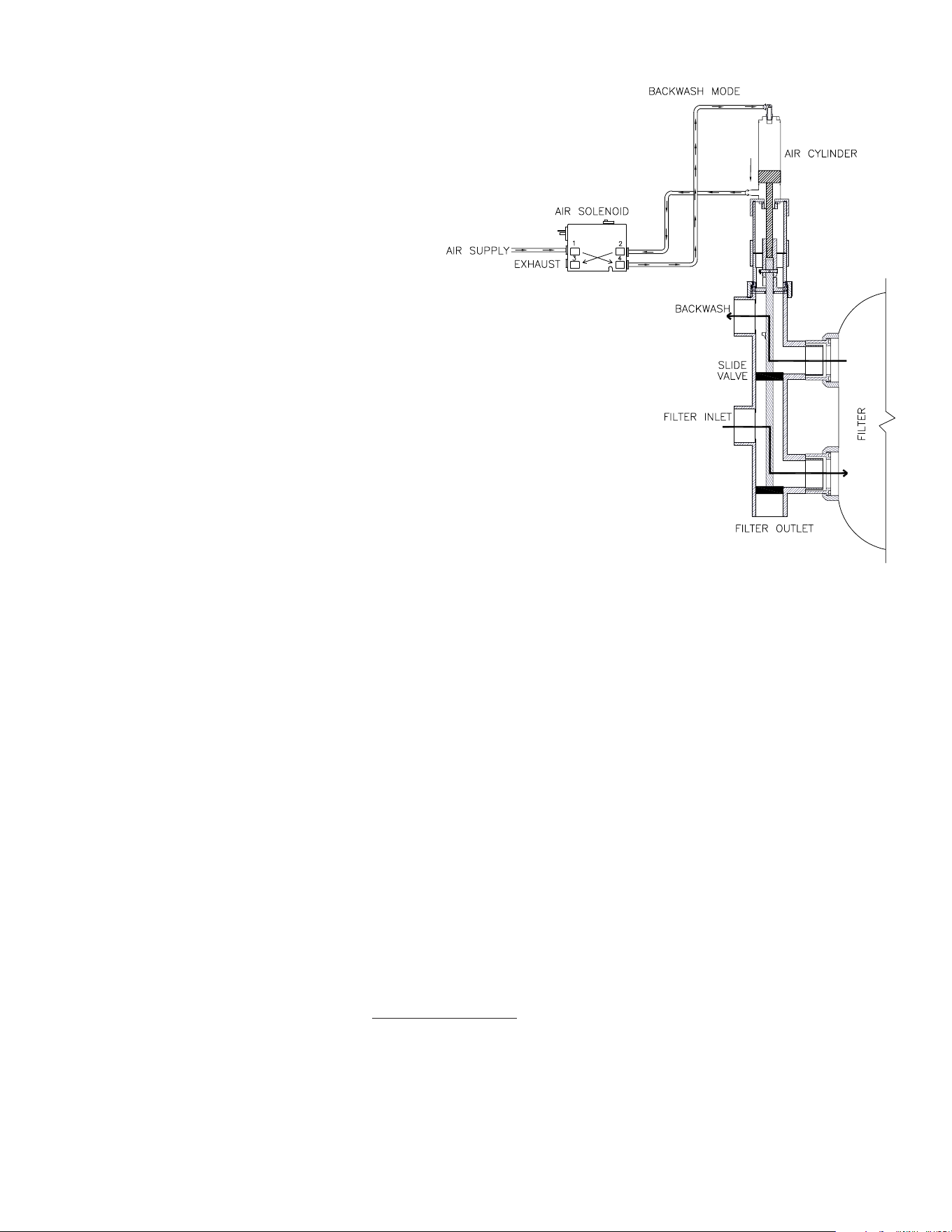
Backwash Mode:
In backwash mode the slide valve is in the down
position. The air solenoid actuates forcing
compressed air to the top of the slide valve air
cylinder. The air pushes the air cylinder plunger
down, pushing down the slide valve shaft. Discs
on the slide valve direct water ow from the lter
inlet to the bottom of the lter pod. Water travels
upwards through the media to the top and out the
backwash line.

36 Mi-T-M
®
WCP Automatic Backwash Series Operator's Manual
H. Add the 2 oz. of chlorine/water solution to the carbon sample in the 4 oz. container.
I. Tightly cap the chlorine/carbon mixture and shake occasionally for 3 minutes.
J. Dip a new strip of chlorine test paper into the liquid part of the 4 oz. container. Do not dip the test paper into the
solid carbon as this will produce incorrect results. Read the directions on the bottle of test strips.
K. Check the reading against the color chart.
1. A reading of zero means the carbon is still active.
a. Reassemble the dispersing section of the Polishing Filter and replace the Polishing Filter Valve.
b. Turn the Filter Pump Switch on.
2. A positive reading means the carbon is inactive and must be recharged or replaced.
REMOVING & REFILLING MEDIA FROM THE MULTIMEDIA & POLISHING FILTER:
1. New media can be ordered from your local distributor using the part numbers listed below.
2. Be certain to wear proper attire such as goggles, gloves, coveralls, dust mask, etc. to protect eyes and skin.
3. Turn o the Filter Pump Switch.
4. Remove the top from the desired lter tank using the wrench provided.
5. Use a vacuum to remove the media from the lter.
6. Ensure the lateral assembly remains centered and ush on the bottom of the tank and the layers are level when
pouring media into the lter tank.
7. Reassemble the dispersing section of the lter tank and replace its corresponding valve.
8. Turn on the Filter Pump Switch. DO NOT backwash Multi-Media Filter until unit has been in operation for 24 hours.
9. Dispose of used media according to EPA standards.
SLIDE VALVE:
The Slide Valve needs to be disassembled so the o-rings can be greased on a monthly basis. Mi-T-M recommends
using a water proof grease and apply the grease liberally.
MAINTENANCE
Model Part number Description Quantity Weight (lbs.)
WCP-10AB-0M10/0M30 19-0560 24" Media Filter 1
33-0303 Gravel #3 100
33-0304 Garnet #12 100
33-0403 Garnet #80 100
33-0306 Filter Ag 50
19-0560 24" Media Filter 1
33-0302 Activated Carbon 110
WCP-30AB-0M10/0M30 19-0562 36" MEDIA FILTER 1
33-0303 GRAVEL #3 300
33-0304 GARNET #12 200
33-0403 GARNET #80 300
33-0306 FILTER AG 100
19-0561 30" MEDIA FILTER 1
33-0302 ACTIVATED CARBON 165
Mi-T-M
®
WCP Automatic Backwash Series Operator's Manual 37
MAINTENANCE:
1. Clean pH AND ORP probes every 1-2 months.
a. Shut o sump pump, wait for drain line to dran and loosen aluminum strain relief around probe to remove.
b. Use water or vinegar and a soft cloth or Q-tip to wipe away build up on the probe.
c. Place probe back in line, with tip at center of piping. Tighten strain relief around probe. DO NOT OVERTIGHTEN.
Note: probes will be damaged if they are allowed to dry out. If they will be exposed to air for more than a few
hours keep tip submerged in water or the storage solution that comes with the probe.
Note: probes have a shelf life of about 1 year so it’s recommended to replace the probes yearly.
2. Calibration of pH meter. You should recalibrate the external meter 1 or 2 times a year. You should also always
recalibrate the meter when a pH probe has been replaced. Follow the calibration instructions below for the pH meter.
An electronic calibrator can be used in place of the buer solutions.
MAINTENANCE
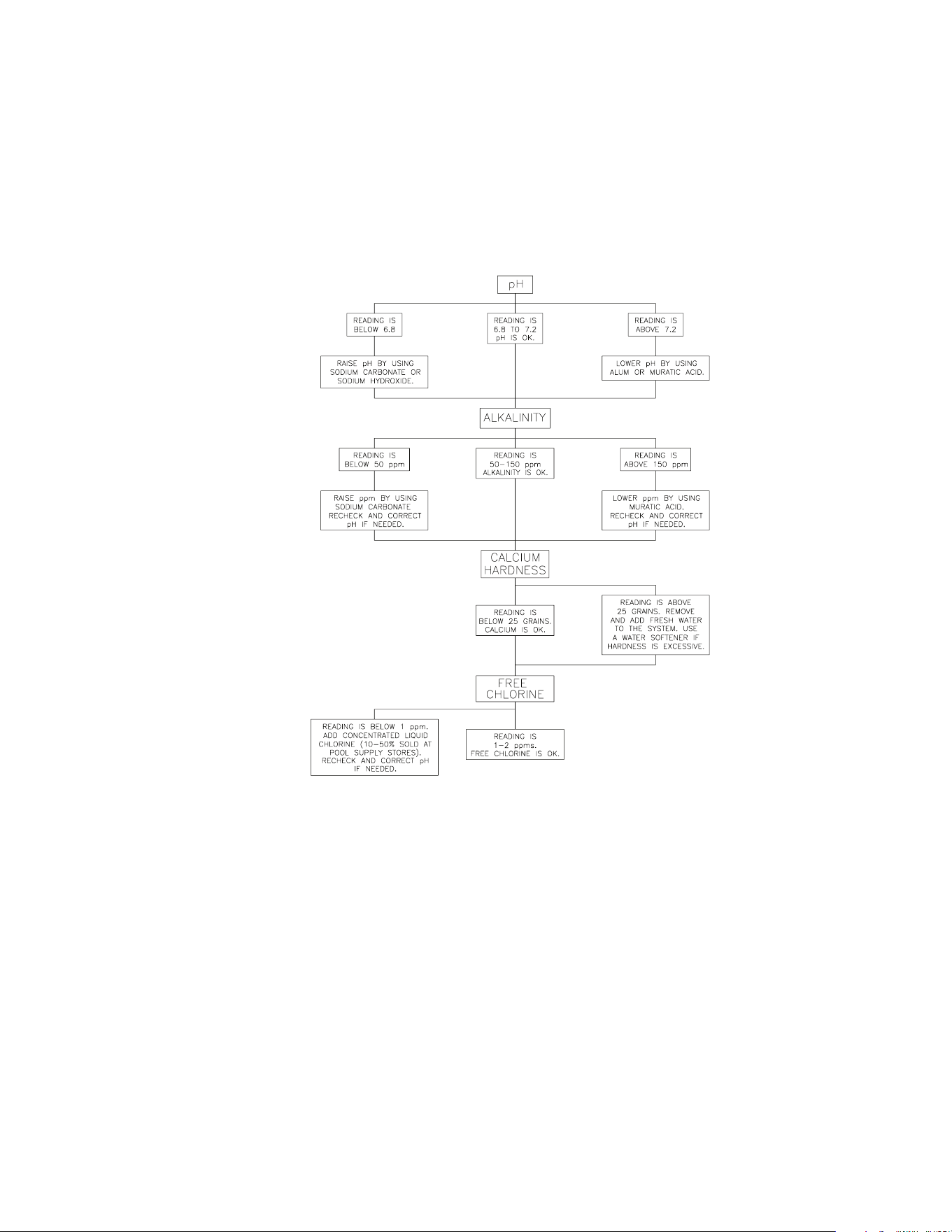
WATER TESTING:
Water chemical makeup should be tested on a weekly basis. With the Sump Pump operating, use a test strip, test
the incoming water to the Holding Tank. (Follow the directions given with your test strips.) Use the ow chart below
to check and correct the following:
1. pH: Acidity and alkalinity in the water. Low pH (acidic) will cause rusty looking water.
2. Alkalinity: Dissolvable salts in the water. Too much alkaline causes cloudiness and reduces lter life.
3. Calcium Hardness: Calcium in the water. Too much calcium creates scale buildup in coils of hot water pressure
washers.
4. *Free Chlorine: Chlorine which is not combined with dirt, oils, etc. Controls odor, bacteria and algae formation.
*If using chlorine as a water purifying agent.
WLP-0015-112398-JJ
38 Mi-T-M
®
WCP Automatic Backwash Series Operator's Manual
MAINTENANCE
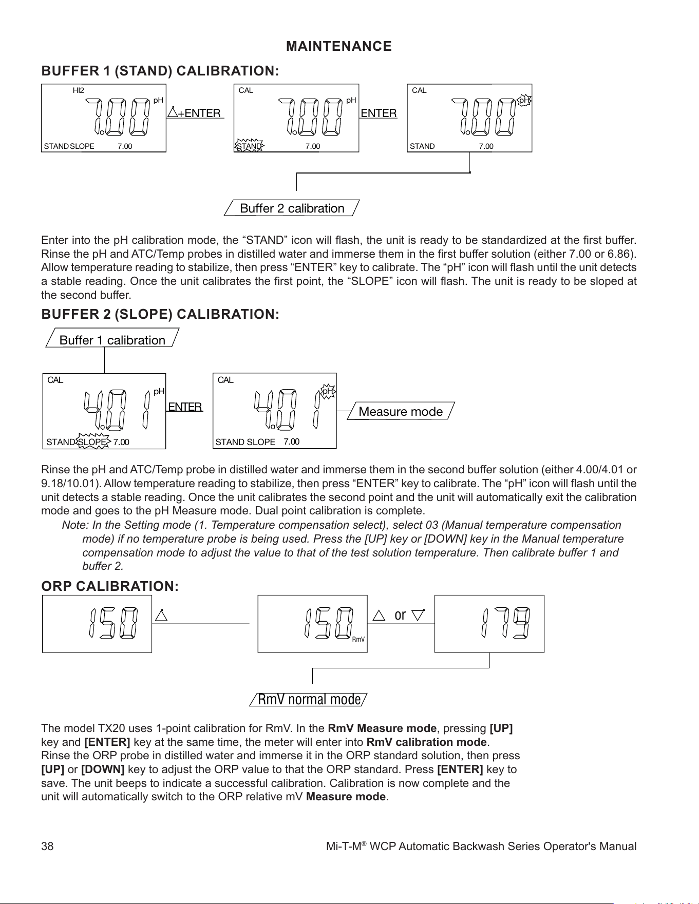
BUFFER 1 (STAND) CALIBRATION:
Enter into the pH calibration mode, the “STAND” icon will ash, the unit is ready to be standardized at the rst buer.
Rinse the pH and ATC/Temp probes in distilled water and immerse them in the rst buer solution (either 7.00 or 6.86).
Allow temperature reading to stabilize, then press “ENTER” key to calibrate. The “pH” icon will ash until the unit detects
a stable reading. Once the unit calibrates the rst point, the “SLOPE” icon will ash. The unit is ready to be sloped at
the second buer.
BUFFER 2 (SLOPE) CALIBRATION:
Rinse the pH and ATC/Temp probe in distilled water and immerse them in the second buer solution (either 4.00/4.01 or
9.18/10.01). Allow temperature reading to stabilize, then press “ENTER” key to calibrate. The “pH” icon will ash until the
unit detects a stable reading. Once the unit calibrates the second point and the unit will automatically exit the calibration
mode and goes to the pH Measure mode. Dual point calibration is complete.
Note: In the Setting mode (1. Temperature compensation select), select 03 (Manual temperature compensation
mode) if no temperature probe is being used. Press the [UP] key or [DOWN] key in the Manual temperature
compensation mode to adjust the value to that of the test solution temperature. Then calibrate buer 1 and
buer 2.
ORP CALIBRATION:
The model TX20 uses 1-point calibration for RmV. In the RmV Measure mode, pressing [UP]
key and [ENTER] key at the same time, the meter will enter into RmV calibration mode.
Rinse the ORP probe in distilled water and immerse it in the ORP standard solution, then press
[UP] or [DOWN] key to adjust the ORP value to that the ORP standard. Press [ENTER] key to
save. The unit beeps to indicate a successful calibration. Calibration is now complete and the
unit will automatically switch to the ORP relative mV Measure mode.
Buffer 2 calibration
+ENTER
ENTER
STAND
CAL
7.00
pH
STAND
SLOPE7.00
pH
HI2
STAND
CAL
7.00
pH
ENTER
Buffer 1 calibration
Measure mode
STAND SLOPE
CAL
7.00
pH
STAND SLOPE
CAL
7.00
pH
RmV normal mode
or
CAL
RmV
CAL
RmV RmV
+ENTER

Mi-T-M
®
WCP Automatic Backwash Series Operator's Manual 39
MAINTENANCE
WINTERIZING:
If you must store your unit in an area where the temperature may fall below 32°F/0°C, you can protect your water recy-
cling treatment system by draining all water from the system.
1. Follow the backwashing/cleaning procedures for the Multi-Media Filter and Polishing Filter
2. Turn all switches on the Control Panel to the OFF position and disconnect power to the Control Panel.
3. Open the check valve near the Sump Pit and drain the water transport line. Drain Sump Pump.
4. Open check valve at the inlet and drain the inlet line.
5. Remove drain plug from Multi-Media Filter and Polishing Filter and open the Air Bleed Valve on each lter. Break
the unions on each side.
6. Remove the drain plug from the Filter Pump.
7. Remove the drain plug from the Transfer Pump.
8. Remove the drain plugs from the Sump Pump.
9. Follow the procedures listed for the solids collection area in the maintenance section. Completely drain the Clarier
Tank.
10. Remove the pH and ORP Sensor Probes and place them in their original containers lled with deionized water.
Store at room temperature.
11. Drain the Ozone System Plumbing and the Ozone Pump.
12. Store all chemicals at room temperature.

40 Mi-T-M
®
WCP Automatic Backwash Series Operator's Manual
SUMP PUMP
Sump Pump will not run.
Sump Pump motor starts and
stops frequently.
TROUBLESHOOTING
SYMPTOM PROBABLE CAUSE REMEDY
Manually ll the inlet pipe with water.
Replace.
Cycle pump in one minute increments
several times to clear air from pump.
Ensure Float 1 is not caught in
plumbing.
Floats are not adjusted correctly in
the Sump Pit.
Not enough water in the Sump Pit.
Float 1 is defective.
High Sump Pump Float in the
Holding Tank has ipped up.
Circuit overload/breaker has tripped.
Motor overload.
Sump Pump impeller is clogged.
There is an air lock in the Sump
Pump.
Sump Pit is not large enough.
Strainer basket in Sump Pump
is clogged.
Water level is below pump inlet.
Clogged impeller or worn pump parts.
Defective switch inside Float 1.
Pump is air locked.
Low voltage.
Clean, repair or replace
Contact your distributor.
Sump Pump will not turn o.
Motor overload.
Sump Pump runs, but there is
little or no water discharge.
Readjust.
Add water to the Sump Pit.
Replace.
Wait for water to drain from holding tank.
Then push High Sump Pump Float down,
or remove excess water in the
Holding Tank.
Reset breaker or replace fuse at
power source..
Allow motor to cool. Motor will
automatically restart when cool.
Sump Pump motor starts and
stops frequently.
Motor is defective.
This is a common occurrence on
initial start-up while pits are lling.
Excessive water ow to reclaim
unit.
Replace pump.
Allow pits to ll.
Turn valve clockwise to reduce ow.
Disconnect power and unclog
impeller.
Allow motor to cool. Motor will
automatically restart when cool.
Expand size of pit.
Ensure wire size is capable of
handling the rated amperage of the
unit. If wire size is correct, contact
your distributor.

Mi-T-M
®
WCP Automatic Backwash Series Operator's Manual 41
ELECTRICAL
No power at Control Panel.
Power Indicator Light is OFF.
Check circuit breaker at power
source or contact your local
distributor.
Check fuses, replace if necessary.
If fuses are OK, contact your
distributor.
CLARIFIER TANK
Water will not ow into the Sump Pump is not turned on. Move Sump Pump Switch to
Clarier Tank. "ON".
Circuit breaker has tripped or is "OFF". Reset or turn breaker "ON".
High Sump Pump Float in Holding Check On/O with voltmeter, repair
Tank is malfunctioning. or replace.
Strainer basket in Sump Pump is Clean, repair, or replace.
clogged.
Dirt is lodged in the check valve. Clean.
Sump Pump impeller is clogged. Disconnect power and clean.
Lines or valves contain frozen water. Allow to thaw. Inject with warm water.
water if necessary.
SHAFT SEALS
Water is leaking at pumps. Damaged stationary shaft seal. Seal ran dry. Ensure seal chamber
is lled with liquid.
Short seal life. Unexpected temperature and Replace.
chemical usage.
TROUBLESHOOTING
SYMPTOM PROBABLE CAUSE REMEDY
Power failure to Control Panel.
Blown fuses inside Control Panel.
on step down transformer.

42 Mi-T-M
®
WCP Automatic Backwash Series Operator's Manual
FILTER PUMP
Filter Pump will not run. Filter Pump Switch is o. Turn switch on.
Circuit overload/breaker has tripped. Reset breaker or replace fuse.
Motor overload. Allow motor to cool. Motor will
automatically restart when cool.
Filter Pump Switch is Replace switch.
malfunctioning.
Low Filter Pump Float or High Filter Check On/O with voltmeter, repair
Pump Float is malfunctioning. or replace.
Filter Pump runs but there is no Plumbing is obstructed. Remove obstruction.
water discharge OR Filter Pump
cycles excessively.
Pump sucking air. Eliminate leaks and tighten all
connections on intake line.
Low water in Holding Tank. Increase ow by opening Water Inlet
Flow Control Valve.
Check valve is leaking or stuck in Clean or replace as necessary.
closed position.
Filters are dirty. Backwash lters.
Lines or valves contain frozen water. Allow to thaw. Inject with warm
water if necessary. Ensure the
Sump Pit remains above
freezing.
Pump impeller is obstructed. Disconnect power and clean.
Pump motor is operating below Contact your local distributor.
maximum RPM.
Filter Pump is hot or turns o. Multi-Media Filter is dirty. Backwash.
Low voltage. Ensure wire size is capable of
handling the rated amperage of the
unit. If wire size is correct, contact
your local distributor.
Motor overload. Allow motor to cool. Motor will
automatically restart when cool.
TROUBLESHOOTING
SYMPTOM PROBABLE CAUSE REMEDY

Mi-T-M
®
WCP Automatic Backwash Series Operator's Manual 43
TRANSFER PUMP
Transfer Pump runs but there is Water is being used elsewhere. Reduce ow to other source or
low water discharge. contact your local distributor.
Low Transfer Pump Float is not Check On/O with voltmeter.
functioning. Repair or replace.
Timer kicked in. Water is recycling Do not run pressure washers while
water is in timed recycle mode.
Rain Water Overow is Reduce ow by adjusting solenoid on
discharging too much water. the Rain Water Overow.
Plumbing is obstructed or too small. Remove obstruction or use larger
plumbing.
Scale buildup in metal piping. Replace with plastic plumbing.
Transfer Pump cycles Solenoid valve(s) is open or stuck Fix Solenoid valve(s) or reduce ow.
excessively. open.
Pump sucking air. Eliminate leaks and tighten all
connections on intake line.
Bladder failure in Pressure Tank. Replace Pressure Tank.
Pressure switch malfunction. Adjust pressure settings.
Too low of pressure in the Pressure Increase pressure.
Tank.
Transfer Pump does not turn o. Wait 10 minutes when no water Normal Operation.
is being discharged.
Pressure switch line is obstructed. Disconnect line and remove
obstruction. Replace.
Pressure switch is out of alignment. Realign or replace.
Pressure switch contacts are frozen. Replace if necessary.
Impeller is obstructed. Contact your local distributor.
TROUBLESHOOTING
SYMPTOM PROBABLE CAUSE REMEDY

44 Mi-T-M
®
WCP Automatic Backwash Series Operator's Manual
SOLENOIDS
Solenoid valve won't turn on. Low or no water pressure. Turn o water, switch solenoids
between valves. Turn on water. If
problem is corrected, replace faulty
solenoid.
No electrical contact to solenoid. Contact your local distributor.
Solenoid valve leaks when turned o. Solenoid is obstructed. Turn o water, remove and clean
solenoid.
Damaged solenoid. Replace.
Solenoid o-ring is misaligned or Realign or replace.
damaged.
Diaphragm seat is dirty. Clean or replace.
Diaphragm is damaged. Replace.
ODOR
Excessive odor in water system. Not enough chemicals in the system Increase the pH and ORP set points.
to maintain water balance.
Water remains dormant in the system Increase timer settings to recycle
too long causing bacteria buildup. water.
CHEMICALS
Excessive chemical usage. pH and ORP Meters are Recalibrate meters or change
calibrated incorrectly or faulty probes. probes.
Low chemical usage (with possible Chemical pumps are not working. Replace chemical hose inside pump.
odor.) Recalibrate pH and ORP Meters.
WATER FLOW
Air shoots from Water Outlet. This is a common occurrence while Air will stop shooting from the water
pump is priming. outlet when pump is primed.
Transfer Pump is sucking air at Eliminate leaks or tighten
suction inlet. connection.
Water will not turn o. Solenoid failure. Repair or replace.
TROUBLESHOOTING
SYMPTOM PROBABLE CAUSE REMEDY

Mi-T-M
®
WCP Automatic Backwash Series Operator's Manual 45
AUTO-BACKWASH SYSTEM
Filter Pump are not fully extended
or retracted. Filter valves do not
extend or retract.
TROUBLESHOOTING
SYMPTOM PROBABLE CAUSE REMEDY
Ensure Air System Inlet pressure is at
or above 60PSI.
Call dealer to repair.
Increase air pressure at Air System In-
let until valve extends. Do not exceed
100PSI. Call dealer to repair.
Check all air lines.
Replace.
Call dealer to repair.
No air pressure.
Debris in Filter Valve.
Lack of lubrication in Filter Valve.
Pinched air line.
Ruptured air line.
Faulty air valve.
Filter Pump cycles continuously
during backwash sequence.
Sump Pump malfunctioning. See
Sump Pump section of troubleshoot-
ing.
Increase inlet ow by opening Water
Inlet Flow Control Valve.
(See PREPARATION, START-UP)
Decrease backwash ow by closing
Filter Control Valve.
(See PREPARATION, START-UP)
Backwash ow rate is higher than
inlet ow rate.
Both Filter Valves extend and
retact at the same time.
Turn Filter Valve Switches to the
"OFF" position whenever the Auto-
Backwash Controller Switch is in the
"ON" position.
Filter Valve Switches are in the
"ON" position.

46 Mi-T-M
®
WCP Automatic Backwash Series Operator's Manual
Clarier Drain
No water exits Clarier Drain dur-
ing automatic cycle.
TROUBLESHOOTING
SYMPTOM PROBABLE CAUSE REMEDY
Manual Solids Drain Valve is
closed.
Drain is clogged.
Automatic Solids Drain Valve
does not fully actuate.
Ensure Air System Inlet pressure is at
or above 60PSI.
Increase air pressure at Air System In-
let until valve actuates. Do not exceed
100PSI. Increase frequency of cycles
by pulling more pins out on Clarier
Drain Valve Timer.
Check all air lines
Replace.
No air pressure.
Sludge is too thick.
Pinched air line.
Ruptured air line.
Manual Solids Drain Valve must
be open fro automatic cycle to work.
See MAINTENANCE, SOLIDS
COLLECTION AREA.
pH / ORP Meters
pH Pump is not running when
HIGH relay is on.
ORP Pump is not running when
LOW relay is on.
Inlet ow must be at least 20GPM.
Flow Switch is clogged.
Flow Switch is malfunctioning. Call
dealer to repair.
Turn to "ON" position.
Flow Switch is not working.
pH or ORP Pump Switch is in the
"OFF" position.

Mi-T-M
®
WCP Automatic Backwash Series Operator's Manual 47
REPLACEMENT PARTS
DESCRIPTION REORDER PART #
pH Sensor Probe .............................................................. 32-0538
ORP Sensor Probe ........................................................... 32-0540
Activated carbon / 55 lbs. ................................................. 33-0302
Gravel / 100 lbs. ............................................................... 33-0303
Garnet #12 / 100 lbs..........................................................33-0304
Garnet #80 / 100 lbs............................. ............................ 33-0403
Filter Ag / 25 lbs. ............................................................... 33-0306
Test Strips / 50 .................................................................. 33-0314
OvEr
Undr
OvEr
OvEr
OvEr
Undr
TROUBLESHOOTING
pH/OPR DISPLAY TEMPERATURE DISPLAY DISPLAY MODE POSSIBLE CAUSE(S) [ACTION(S)]
pH > 16.00pH [Recalibrate], replace probe
pH > -2.00pH [Recalibrate], replace probe
a. Temperature > 120.0 °C [Bring buer
solution to lower temperature.] [Replace
temperature probe.]
b. No temperature sensor. [Adjust the man-
ual temperature to -10~120 °C.]
a. Temperature > -10.0 °C [Bring buer
solution to higher temperature.] [Replace
temperature probe.]
b. No temperature sensor. [Adjust the man-
ual temperature to -10~120 °C.]
Absolute ORP mV > +1999 mV
a. Bring solution down to lower ORP
b. Recalibrate
c. Replace probe
Absolute ORP mV > -1999 mV
a. Bring solution up to higher ORP
b. Recalibrate
c. Replace probe
-10.0~120.0 °C
-10.0~120.0 °C
OvEr
Undr
Temperature reading
Temperature reading
pH measure mode
pH measure mode
pH measure mode
pH measure mode
Absolute ORP mV or
relative ORP
Absolute ORP mV or
relative ORP

48 Mi-T-M
®
WCP Automatic Backwash Series Operator's Manual
STATEMENT OF WARRANTY
Mi-T-M warrants all parts (except those referred to below) of your new WCP Water recycling Treatment system
to be free from defects in materials and workmanship during the following periods:
For One (1) Year from the date of original purchase:
Defective parts not subject to normal wear and tear will be repaired or replaced at
Mi-T-M's option during the warranty period. In any event, reimbursement is limited to the purchase price
paid.
EXCLUSIONS
1. The motor is covered under separate warranty by its respective manufacturer and is subject to the terms
set forth therein.
2. Normal wear parts:
Seals Filters Gaskets
O-rings Packings Pistons
Valve Assembly Brushes Filtering Media
Sensors
3. Parts damaged due to:
-normal wear, misapplication, modications/alterations, abuse,
-operation at other than recommended speeds, pressures or temperature,
-the use of caustic liquids,
-chloride corrosion or chemical deterioration,
-uctuations in electrical or water supply,
-operating unit in an abrasive, corrosive or freezing environment.
4. Parts damaged by failure to follow recommended:
-installation, operating and maintenance procedures.
5. This warranty does not cover the cost of:
-normal maintenance or adjustments,
-labor charges,
-transportation charges to Service Center,
-freight damage.
6. The use of other than genuine Mi-T-M parts will void warranty. Parts returned, prepaid to Mi-T-M's factory
or to an Authorized Service Center will be inspected and replaced free of charge if found to be defective
and subject to warranty. There are no warranties which extend beyond the description of the face hereof.
Under no circumstances shall Mi-T-M bear any responsibility for loss of use of the unit, loss of time or
rental, inconvenience, commercial loss or consequential damages.

Mi-T-M
®
WCP Automatic Backwash Series Operator's Manual 49