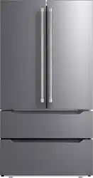
Repair Manual
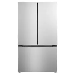
Model:VEFFD3620RISL
Service manual
Content
Technician SAFETY Precautions ................................................................................................................2
Chapter l: Product Functional Features.......................................................................................................3
Chapter 2: Product Appearance Structure and Component Names ............................................................4
Chapter 3: Main Technical Parameters of the Product................................................................................7
Chapter 4: Product Function Operation Instructions...................................................................................8
Chapter 5: Electrical Schematic and Wiring Diagram ..............................................................................11
Chapter 6: Control Principles, Parameters, and Detection Methods.........................................................13
Chapter 7: Refrigeration Principle and Pipeline Cycle Diagram ..............................................................16
Chapter 8: Disassembly Instructions for Main Components.....................................................................17
Chapter 9: Typical Fault Diagnosis and Troubleshooting.........................................................................23
1
Service manual
Technician SAFETY Precautions
Please observe the following safety precautions in order to use safely and correctly the refrigerator
and to prevent accident and danger during repair
● To avoid electrical shock, disconnect power cord from wall outlet and wait for more
than three minutes before handling electronic components or capacitors.
● Disconnect power cord from wall outlet before replacing or repairing electric components.
● After unplugging the refrigerator, wait at least 5 minutes before plugging it back.
● Position the power cord in a manner to prevent damage when moving the refrigerator back into
position.
● Do not plug a damaged power cord into the electrical outlet.
● Advise the consumer when the refrigerator is not on a dedicated electrical circuit as overloading may
cause fire.
● Do not plug the refrigerator into a receptacle that is not properly grounded or not properly
polarized or has incorrect voltage level.
● Advise the consumer when any of the installation requirements are not met.
● Use only factory authorized parts and repair procedures.
● Advise the consumer to only perform procedures listed in the owner’s manual.
● When evidence of moisture is present in or on any electrical component or circuit, unplug the
refrigerator Completely dry or replace the component, determine the cause and take proper steps
to prevent reoccurrence.
● To prevent physical injury, do not touch moving parts such as fan blade or icemaker rake.
● Follow all safety precautions listed in the owner’s manual and advise the consumer as needed.
● Remove any objects on top of the refrigerator, and any open containers inside the refrigerator
before moving the refrigerator.
● When scrapping any refrigerator or freezer, remove the door/drawer gaskets to prevent children from
suffocation.
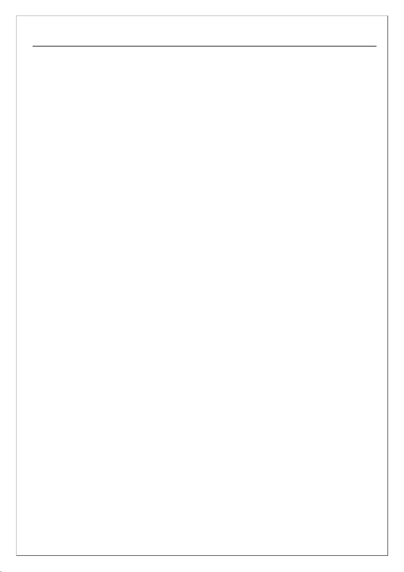
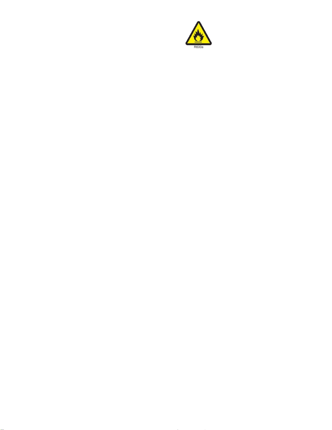
● This refrigerator contains flammable refrigerant. Follow all relative company, federal, and local
safety guidelines
To avoid risk of electrical shock that can cause death or severe personal
injury, disconnect unit from power before servicing unless tests require
power.
2
Technician R600a Sealed System Repair Guide
The following is in addition to or serves as a reminder of the established and prescribed company service
procedures for R600a sealed system diagnosis & repair.
1. This refrigerator contains flammable refrigerant. Follow all relative company, federal,
and local safety guidelines.
2. No torch or heat gun is to be used on or near any product charged with flammable refrigerant.
3. When the service request indicates a possible sealed system issue, the product and
service area must be tested for combustible vapor using an approved combustible gas
detector prior to and during servicing the sealed system.
4. Communicate with consumer concerning flammable refrigerant precautions.
5. Do not apply power to the compressor terminals with the protective cover removed.
6. Unless a technician is certified and equipped for R600a sealed system repair, the sealed
system must be diagnosed without system entry or access.
7. All sealed system connection points (joints) must be analyzed before ordering parts to ensure that all
connections can be completed.
8. Dry-powder class C fire extinguisher is nearby and accessible.
9. The service area must be well ventilated.
10. The product is grounded during repair to prevent static electrical spark.
11. Using proper equipment, temporarily recover the system to the deepest level possible while shaking the
compressor periodically.
12. Bring the system vacuum to atmospheric pressure using regulated dry oxygen-free
nitrogen or if leak testing is needed, pressurize up the low-side design pressure.
13. If not leak testing and system at atmospheric pressure, purge the system with dry
nitrogen following prescribed procedure steps then cut all necessary connections using
tubing cutter and cap-tube cutter.
14. Replace all needed sealed system components, leaving the filter-drier replacement for last.
15. Pressure test using dry oxygen-free nitrogen at no greater than low-side design pressure.
16. Safely expel the nitrogen from the system.
17. Complete the deep evacuation process and recharge using virgin R600a refrigerant
following the prescribed method.
18. Cap off and test access ports for leakage.
19. Add red color to access ports tubing following AHAM guideline.
20. Vent outdoors the recovered and unused R600a refrigerant following the prescribed method.
Service manual
Chapter l: Product Functional Features
1. Refrigerant R600a and foaming agent are hydrocarbons, which do not damage the ozone layer or
produce a greenhouse effect. The freezer automatically defrosts, saving the trouble of manual defrosting;
2. Integrating technologies such as quick freezing, energy conservation, and noise reduction, optimizing
the refrigeration system to achieve energy-saving goals and minimize noise;
3. Mouldproof and antibacterial detachable door seal, clean and hygienic, easy to clean;
4. Hidden hinge system, sturdy and beautiful, can achieve automatic door closing and door opening limit;
5. Fully open refrigerated drawer door with three metal slides and self closing function;
3
Service manual
Chapter 2: Product Appearance Structure and Component Names
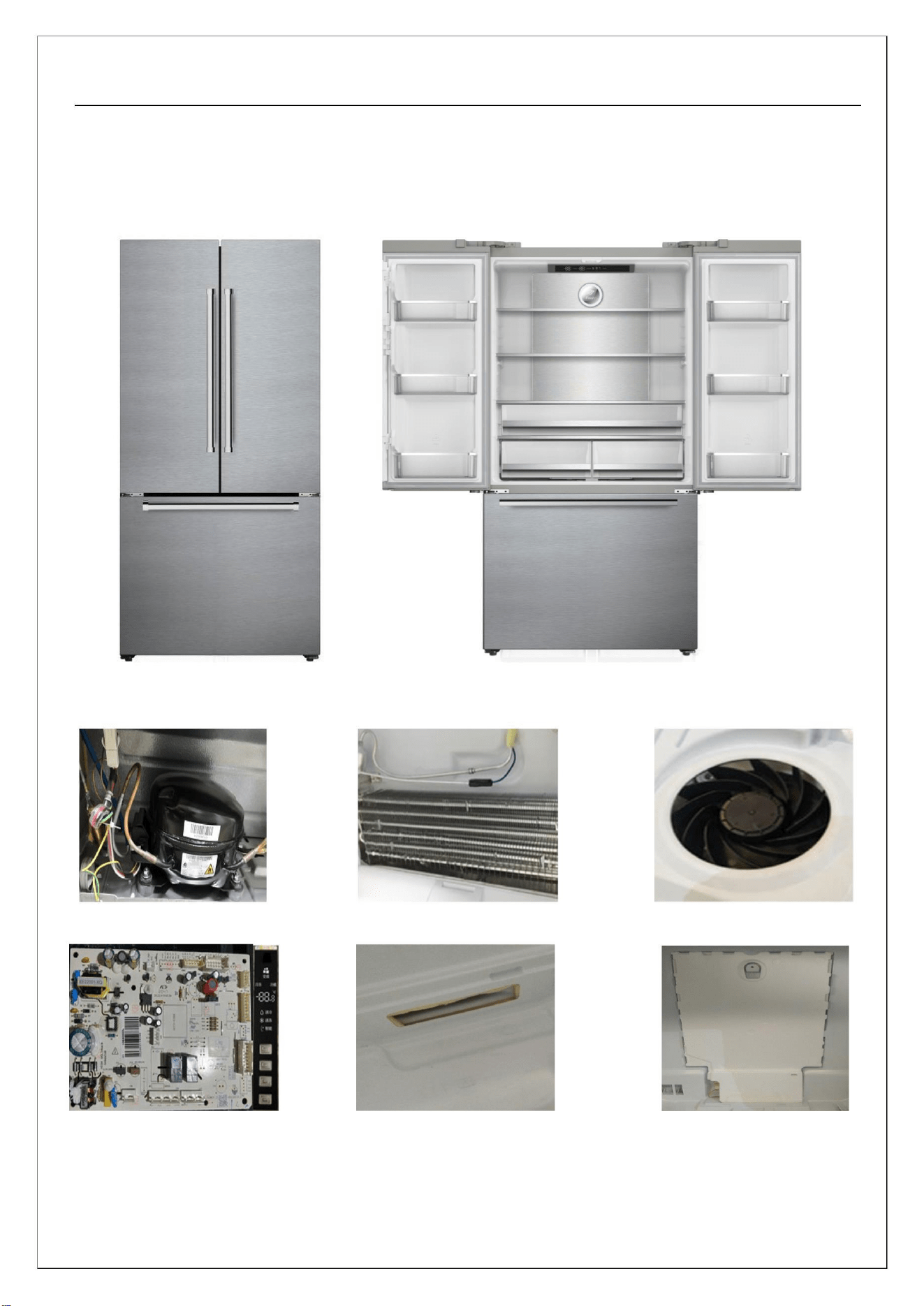
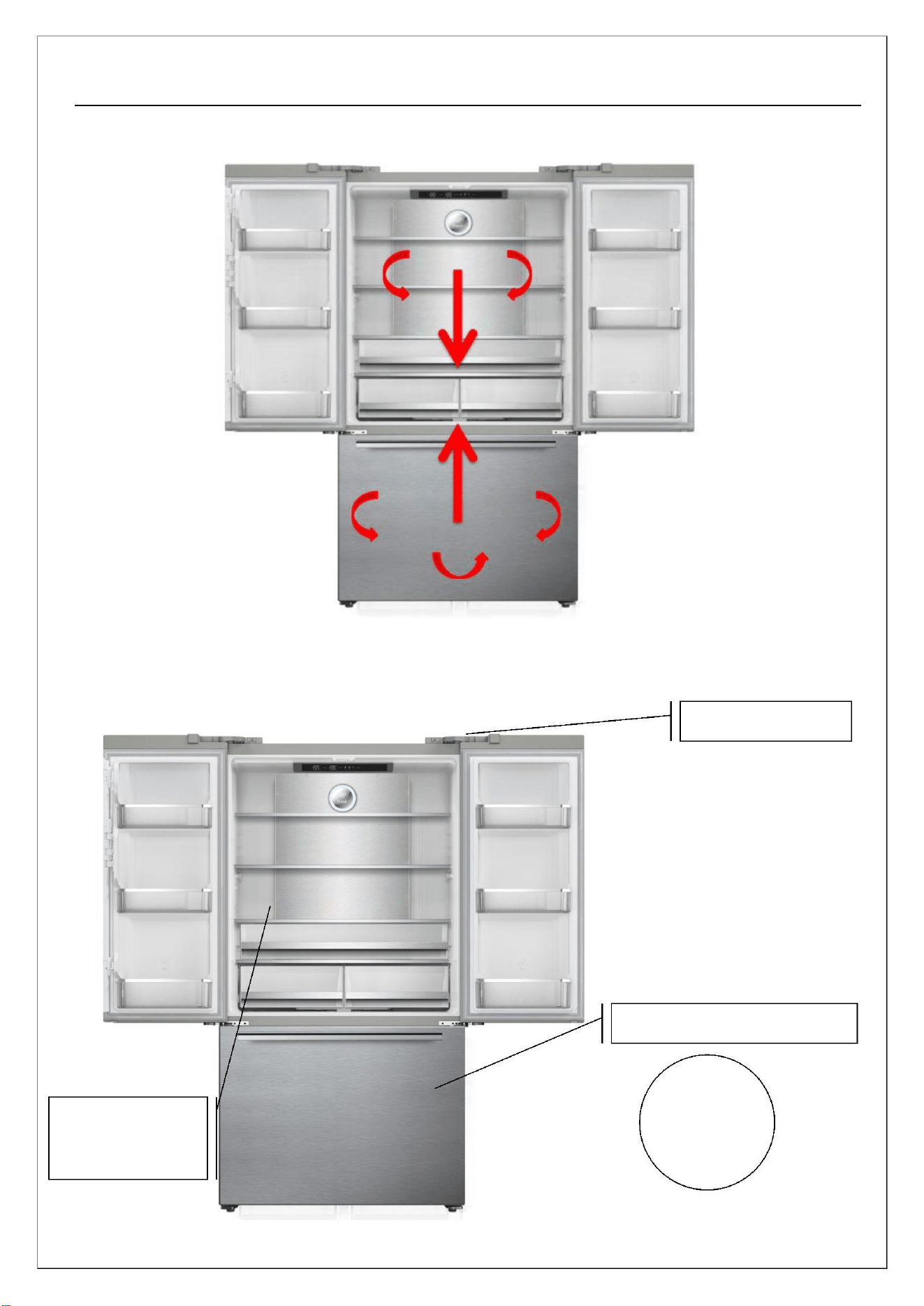
1. Product appearance
2. Main component
Compressor
Evaporator heater assembly
Freezer motor
Main PCB and display
Damper
Fridge air duct foaming
4
Service manual
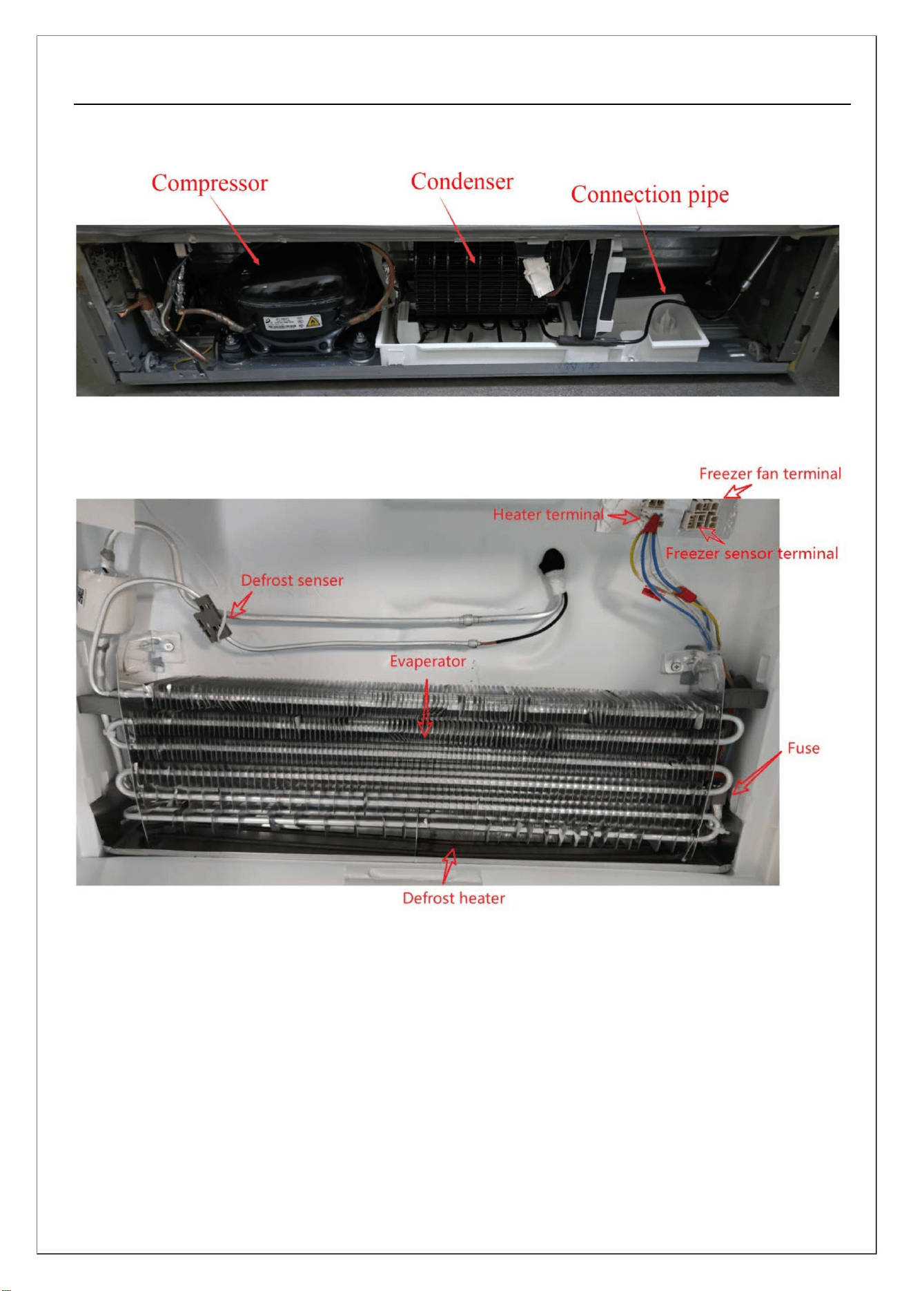
Compressor chamber view
Composition of refrigeration evaporator
5
Service manual
Air direction view between fridge and freezer
Freezer senser and fridge sensor location
Ambient senser
Freezer temperature senser
Fridge
temperature
senser
6
Service manual
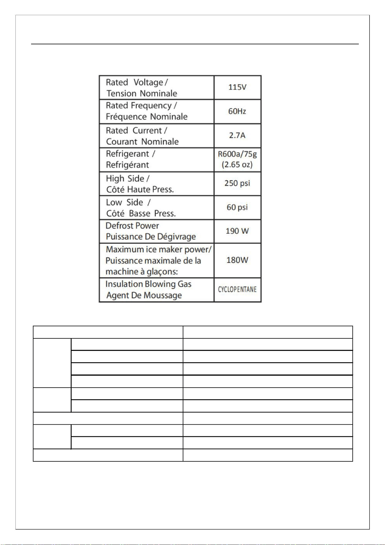
Chapter 3: Main Technical Parameters of the Product
Item Name
Complete Appliance Model
Defrost-sensor(FD-Sensor)
Freezer-sensor(F-Sensor)
Refrigerator-sensor(R-Sensor)
Temperature and humidity sensor
Freezer Fan(F-FAN)
In Evaporator Assembly
In Louver Assembly
Sensor
Motor
Heater
In multi flow duct assembly
Between Top Cabinet and Top Cover Hinge
12V NIDEC GW12Z12MS3MB
12V NIDEC Z15I12MS3A5
Condenser Fan(C-FAN)
Damper
DC12V FBZA-1750
Defrost-Heater
AC110-120V 230W(Cycles based on temps)
DC12V 8W(Cycles based on temps)
AC250V , 10A , 72℃
Flip beam heating wire
Fuse Temp (Defrost)
7
Service manual
Chapter 4: Product Function Operation Instructions
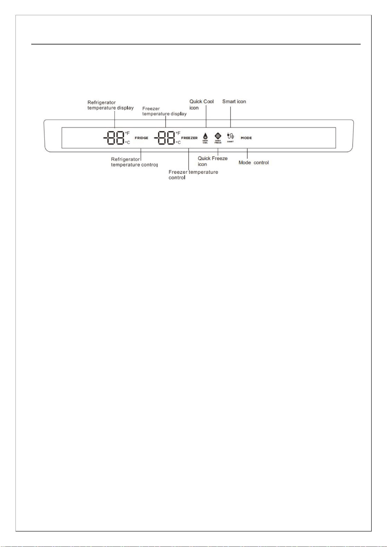
1.Display
● When powered on for the first time, sound the startup bell and then enter the normal operation display;
● Normal operation display digital area: When there is a fault, the fault code will be displayed three
hours later, and when there is no fault, the set temperature of the corresponding refrigeration room
will be displayed; (Press Fridge & Freezer temp buttons simultaneously to reveal a hidden fault)
● When working under normal conditions, there is no door opening action or button operation, and the
display screen will turn off after 20 seconds; Every time there is a door opening action or button
operation, the display screen returns to normal display; When a fault occurs, the display screen will
always light up and display the fault code;
2. Locking and unlocking
● In a non locked state, hold down the lock button continuously for 3 seconds to enter the locked state.
The lock beep sounds and the lock icon displays as locked;
● In the locked state, continue to press and hold the lock button for 3 seconds to enter the non locked
state. The unlock beep sound will sound, and the lock icon will display as the unlocked state;
The following key operations must be performed in a non locked state. If operating in a locked state, the
lock icon flashes to prompt;
2.Temperature setting of each room
Each time the temperature zone selection button is pressed, the icons for the refrigerated and frozen
temperature zones will cycle and flash in the following order;
8
Service manual
Fridge → Freezer → Fridge
When the icon for the refrigeration/freezing temperature zone flashes, every time the temperature
adjustment button is pressed, the integer digit in the digital display area flashes. Repeating this button
can adjust the integer digit. When the integer digit flashes, pressing the OK button switches to the
decimal digit flashing to set the decimal digit. At this time, pressing the OK button or 5S will
automatically complete the temperature setting, and the icon will stop flashing;
The temperature setting range of the refrigeration room is 2.0~8.0 °C/25.6℉~46.4; The temperature
setting range of the freezer is -23.0~- l 5.0 °C/-9.4~5℉;
2.Fridge shutdown function
When the refrigerated temperature zone flashes, press and hold the "Temperature Zone" selection button
for 5 seconds to select whether to turn on or off the refrigerated shutdown function. The refrigerated
shutdown digital display window displays "OF". When the refrigerated shutdown is turned off and the
refrigerated temperature zone flashes, press and hold the "Temperature Zone" selection button for 5
seconds to restore the refrigerated room function;
3.Intelligent, quick freezing, and quick cooling modes
Each time the mode key is pressed, the intelligent, quick freezing, quick freezing/quick cooling, quick
cooling and no cycle setting will be set. If any mode is set or cancelled, the icon will turn on/off to
select/cancel the mode. When setting the intelligent mode, the refrigeration is automatically set to
8 °C/46.4℉, and the freezer is automatically set to - l5 °C/5℉; When exiting the intelligent mode, the
set temperature of the refrigeration room and freezer will automatically return to the set temperature
before the intelligent mode; When setting the quick cooling mode, the refrigeration system will
automatically set 2 °C/25.6℉. When exiting the quick cooling mode, the set temperature in the
refrigeration room will automatically return to the set temperature before the quick cooling mode; When
setting the quick freezing mode, it will enhance the cooling capacity of the freezer. In the quick freezing
state, the temperature setting of the freezer can be selected and modified. In the quick freezing state, the
maximum operating time of the refrigerator compressor is 24 hours;
4.Refrigerator door opening prompt and alarm
When the refrigerator door remains open for l minute without closing, the buzzer will sound three times,
9
Service manual
and then three times every 30 seconds until the refrigeration and freezer doors are closed.
5.Power off memory
After the refrigerator is powered off, it will still operate according to the set state before the power
outage when it is powered on again (memory will start 10 seconds after the set temperature or the mode
ends).
6.Fault display
When the digital display window on the refrigerator operation screen displays "FS", "dS", "rS", "dH",
"FF", "CO", "CF", "EL" in whole digits, and "E" in decimal digits, it indicates that the refrigerator has
malfunctioned. In some cases, the refrigerator can still cool, but it should be repaired as soon as possible
to achieve optimal operation of the refrigerator.
10
Service manual
Chapter 5: Electrical Schematic and Wiring Diagram
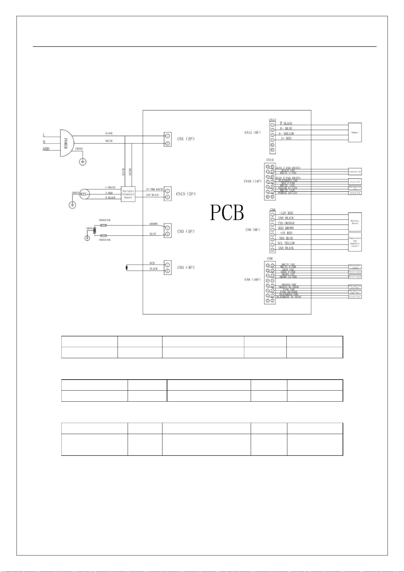
1. Electrical schematic diagram
CN1(POWER)
Item
Pin No
1,3
Plugged in
Un-plugged
Remarks
POWER
110-120V/AC
0
/
CN3(DEFROST-HEATER)
Item
Pin No
1,3
Off
Remarks
/
Defrost heater
Cycles based on temps
/
CN4(Flip beam heater)
Item
Pin No
1,2
Off
Remarks
/
Flip beam heater
12VDC,8W、Cycles
based on temps
/
11
Service manual
CN6(Sensor&Switch)
Item
Pin No
15,16
13,14
11,12
7,8
Open(Voltage)
5V DC
Close(off)
Remarks
R-SNR
/
/
/
/
/
/
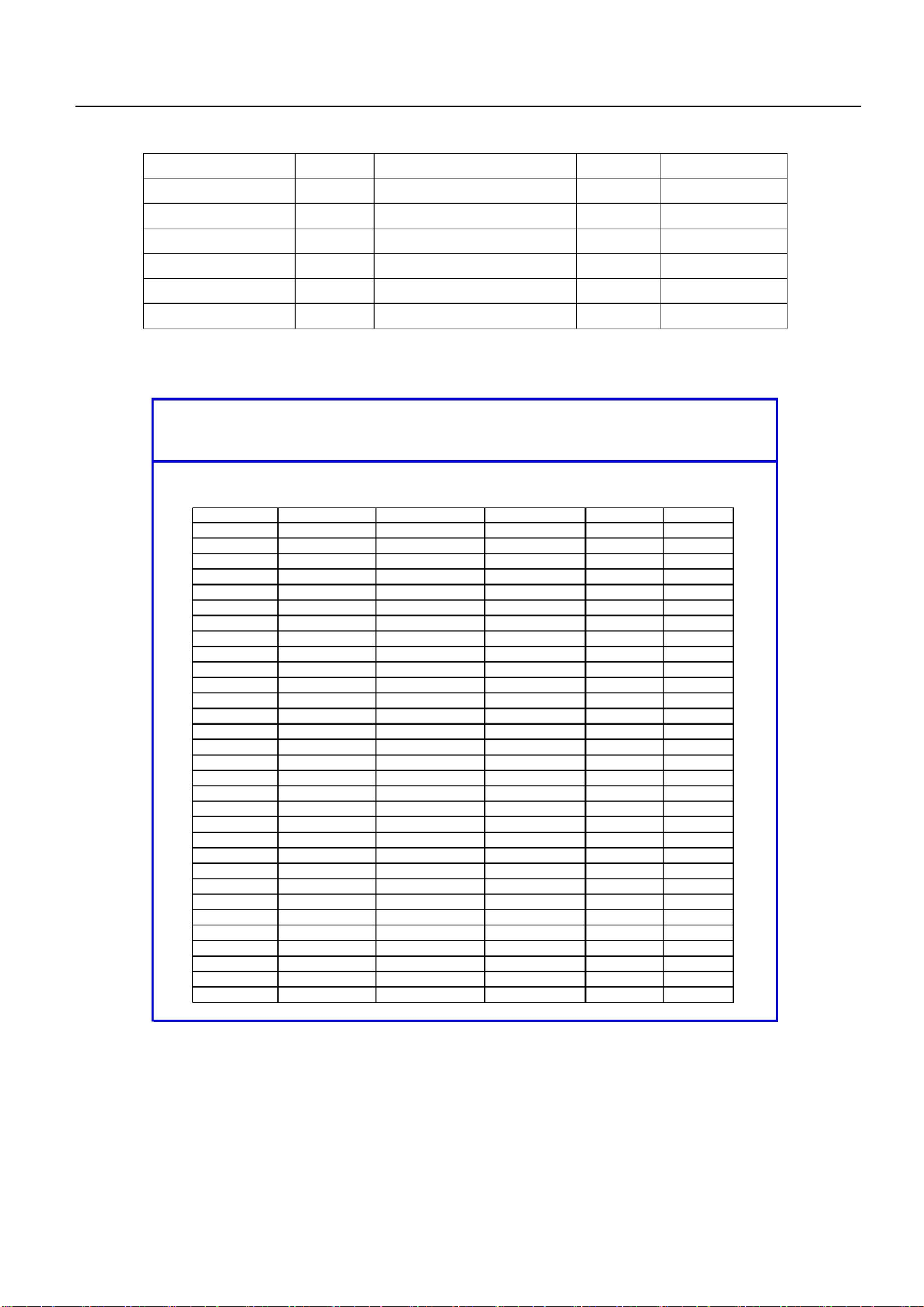
Sensor Table1
F-SNR
5V DC
Sensor Table2
FD-SNR
RL-Door
RR-Door
FL-Door
5V DC
Sensor Table1
5V DC
/
/
/
5,6
5V DC
3,4
5V DC
Sensor Table1: Fridge & Defrost sensors
Name: AT5061G3839G
Series: AT TYPE
Specificattion
Page:
Kohm
K
1/4
Resisitance: R(5)
B constant: B(5/25)
5.06
± 2.00%
± 2.00%
date:
2005.06.29
3839.0
R-T TABLE
Temp.(℉)
-22
R(min)
33.324
31.344
29.494
27.766
26.151
24.641
23.228
21.906
20.668
19.507
18.420
17.400
16.444
15.546
14.703
13.911
13.167
12.468
11.810
11.191
10.608
10.059
9.543
R(cent)
35.353
33.210
31.212
29.347
27.606
25.980
24.461
23.041
21.713
20.470
19.306
18.216
17.195
16.237
15.340
14.497
13.706
12.964
12.266
11.610
10.994
10.414
9.868
R(max)
37.489
35.173
33.016
31.005
29.130
27.381
25.749
24.225
22.802
21.471
20.227
19.063
17.973
16.953
15.997
15.102
14.262
13.474
12.735
12.041
11.389
10.777
10.201
9.660
DR(min)
DR(max)
-5.7%
-5.6%
-5.5%
-5.4%
-5.3%
-5.2%
-5.0%
-4.9%
-4.8%
-4.7%
-4.6%
-4.5%
-4.4%
-4.3%
-4.1%
-4.0%
-3.9%
-3.8%
-3.7%
-3.6%
-3.5%
-3.4%
-3.3%
-3.2%
-3.1%
-3.0%
-2.9%
-2.8%
-2.7%
-2.6%
-2.5%
6.0%
5.9%
5.8%
5.6%
5.5%
5.4%
5.3%
5.1%
5.0%
4.9%
4.8%
4.6%
4.5%
4.4%
4.3%
4.2%
4.1%
3.9%
3.8%
3.7%
3.6%
3.5%
3.4%
3.3%
3.2%
3.0%
2.9%
2.8%
2.7%
2.6%
2.5%
20.2
-18.4
-16.6
-14.8
-13
-11.2
-9.4
-7.6
-5.8
-4
-2.2
-0.4
1.4
3.2
5
6.8
8.6
10.4
12.2
14
15.8
17.6
19.4
21.2
23
24.8
26.6
28.4
30.2
32
9.056
8.596
9.355
8.871
9.151
8.671
8.163
7.755
8.415
7.986
8.220
7.795
7.369
7.005
7.581
7.199
7.395
7.017
6.662
6.661
6.337
6.838
6.498
Service manual
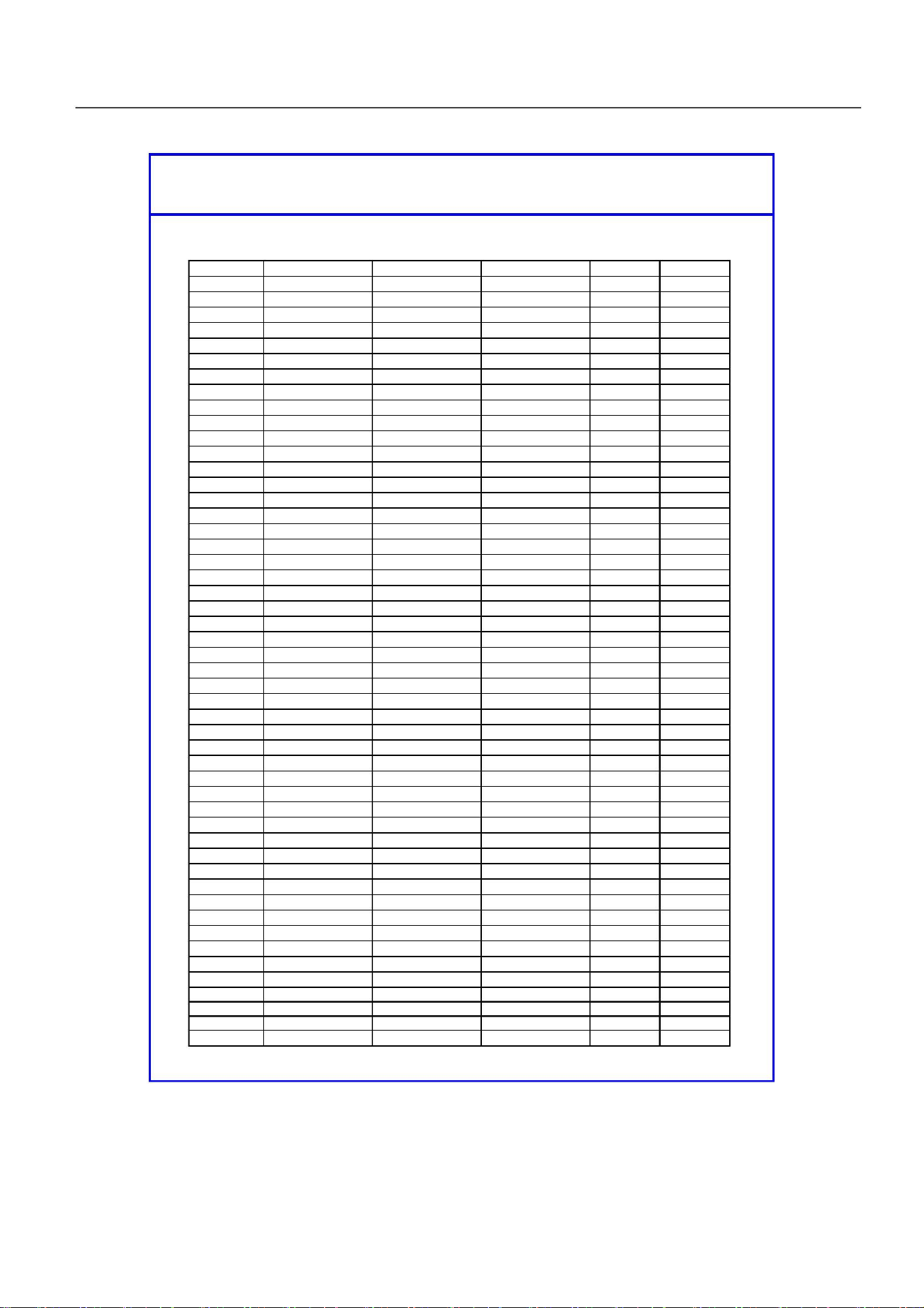
Name: AT5061G3839G
Series: AT TYPE
Specificattion
Page:
2/4
Resisitance: R(5)
5.06
Kohm
K
± 2.00%
± 2.00%
date:
2005.06.29
B constant: B(5/25)
3839.0
R-T TABLE
Temp.(℉)
33.8
35.6
37.4
39.2
41
R(min)
6.029
5.739
5.465
5.205
4.959
4.717
4.488
4.271
4.067
3.873
3.690
3.516
3.352
3.196
3.048
2.908
2.775
2.649
2.530
2.416
2.309
2.206
2.109
2.016
1.929
1.845
1.766
1.690
1.618
1.549
1.484
1.422
1.363
1.306
1.253
1.201
1.152
1.106
1.061
1.019
0.978
0.939
0.902
0.867
0.833
0.801
0.770
0.740
0.712
0.685
R(cent)
6.177
5.874
5.587
5.316
5.060
4.818
4.588
4.371
4.166
3.971
3.787
3.612
3.446
3.289
3.140
2.999
2.864
2.737
2.616
2.501
2.391
2.287
2.188
2.094
2.005
1.920
1.838
1.761
1.688
1.618
1.551
1.487
1.426
1.368
1.313
1.260
1.210
1.162
1.116
1.072
1.030
0.990
0.952
0.915
0.880
0.847
0.815
0.784
0.755
0.727
R(max)
6.326
6.009
5.710
5.428
5.161
4.919
4.689
4.472
4.266
4.070
3.885
3.709
3.542
3.384
3.234
3.091
2.955
2.826
2.703
2.587
2.476
2.370
2.270
2.174
2.083
1.996
1.914
1.835
1.760
1.688
1.620
1.554
1.492
1.433
1.376
1.322
1.270
1.221
1.173
1.128
1.085
1.044
1.004
0.966
0.930
0.895
0.862
0.830
0.800
0.770
DR(min)
DR(max)
-2.4%
-2.3%
-2.2%
-2.1%
-2.0%
-2.1%
-2.2%
-2.3%
-2.4%
-2.5%
-2.6%
-2.7%
-2.7%
-2.8%
-2.9%
-3.0%
-3.1%
-3.2%
-3.3%
-3.4%
-3.5%
-3.5%
-3.6%
-3.7%
-3.8%
-3.9%
-4.0%
-4.0%
-4.1%
-4.2%
-4.3%
-4.4%
-4.5%
-4.5%
-4.6%
-4.7%
-4.8%
-4.8%
-4.9%
-5.0%
-5.1%
-5.1%
-5.2%
-5.3%
-5.4%
-5.4%
-5.5%
-5.6%
-5.7%
-5.7%
2.4%
2.3%
2.2%
2.1%
2.0%
2.1%
2.2%
2.3%
2.4%
2.5%
2.6%
2.7%
2.8%
2.9%
3.0%
3.1%
3.2%
3.3%
3.4%
3.4%
3.5%
3.6%
3.7%
3.8%
3.9%
4.0%
4.1%
4.2%
4.3%
4.4%
4.4%
4.5%
4.6%
4.7%
4.8%
4.9%
5.0%
5.0%
5.1%
5.2%
5.3%
5.4%
5.5%
5.5%
5.6%
5.7%
5.8%
5.9%
6.0%
6.0%
42.8
44.6
46.4
48.2
50
51.8
53.6
55.4
57.2
59
60.8
62.6
64.4
66.2
68
69.8
71.6
73.4
75.2
77
78.8
80.6
82.4
84.2
86
87.8
89.6
914.
93.2
95
96.8
98.6
100.4
102.2
104
105.8
107.6
109.4
111.2
113
114.8
116.6
118.4
120.2
122
Service manual
Name: AT5061G3839G
Series: AT TYPE
Specificattion
Page:
Kohm
K
3/4
Resisitance: R(5)
B constant: B(5/25)
5.06
± 2.00%
± 2.00%
date:
2005.06.29
3839.0
R-T TABLE
Temp.(℉)
123.8
125.6
127.4
129.2
131
R(min)
0.659
0.634
0.611
0.588
0.566
0.545
0.525
0.506
0.488
0.470
0.453
0.437
0.421
0.407
0.392
0.379
0.365
0.353
0.340
0.329
0.318
0.307
0.296
0.286
0.277
0.267
0.259
0.250
0.242
0.234
0.226
0.219
0.212
0.205
0.198
0.192
0.186
0.180
0.174
0.169
0.164
0.159
0.154
0.149
0.144
0.140
0.136
0.132
0.128
0.124
R(cent)
0.700
0.674
0.649
0.625
0.603
0.581
0.560
0.540
0.521
0.502
0.485
0.468
0.451
0.436
0.421
0.406
0.392
0.379
0.366
0.354
0.342
0.331
0.320
0.309
0.299
0.289
0.280
0.271
0.262
0.253
0.245
0.237
0.230
0.223
0.216
0.209
0.202
0.196
0.190
0.184
0.179
0.173
0.168
0.163
0.158
0.153
0.149
0.144
0.140
0.136
R(max)
0.742
0.716
0.690
0.665
0.642
0.619
0.597
0.576
0.556
0.537
0.518
0.500
0.483
0.467
0.451
0.436
0.421
0.407
0.394
0.381
0.368
0.356
0.344
0.333
0.323
0.312
0.302
0.293
0.283
0.274
0.266
0.258
0.250
0.242
0.234
0.227
0.220
0.214
0.207
0.201
0.195
0.189
0.183
0.178
0.173
0.168
0.163
0.158
0.153
0.149
DR(min)
DR(max)
-5.8%
-5.9%
-5.9%
-6.0%
-6.1%
-6.2%
-6.2%
-6.3%
-6.4%
-6.4%
-6.5%
-6.6%
-6.6%
-6.7%
-6.8%
-6.8%
-6.9%
-7.0%
-7.0%
-7.1%
-7.1%
-7.2%
-7.3%
-7.3%
-7.4%
-7.5%
-7.5%
-7.6%
-7.6%
-7.7%
-7.8%
-7.8%
-7.9%
-7.9%
-8.0%
-8.1%
-8.1%
-8.2%
-8.2%
-8.3%
-8.3%
-8.4%
-8.5%
-8.5%
-8.6%
-8.6%
-8.7%
-8.7%
-8.8%
-8.8%
6.1%
6.2%
6.3%
6.4%
6.4%
6.5%
6.6%
6.7%
6.7%
6.8%
6.9%
7.0%
7.1%
7.1%
7.2%
7.3%
7.4%
7.4%
7.5%
7.6%
7.6%
7.7%
7.8%
7.9%
7.9%
8.0%
8.1%
8.2%
8.2%
8.3%
8.4%
8.4%
8.5%
8.6%
8.6%
8.7%
8.8%
8.9%
8.9%
9.0%
9.1%
9.1%
9.2%
9.3%
9.3%
9.4%
9.5%
9.5%
9.6%
9.7%
132.8
134.6
136.8
138.2
140
141.8
143.6
145.4
147.2
149
150.8
152.6
154.4
156.2
158
159.8
161.6
163.4
165.2
167
168.8
170.6
172.4
174.2
176
177.8
179.6
181.4
183.2
185
186.8
188.6
190.4
192.2
194
195.8
197.6
199.4
201.2
203
204.8
206.6
208.4
210.2
212
Service manual
Name: AT5061G3839G
Series: AT TYPE
Specificattion
Page:
Kohm
K
4/4
Resisitance: R(5)
B constant: B(5/25)
5.06
± 2.00%
± 2.00%
date:
2005.06.29
3839.0
R-T TABLE
Temp.(℉)
213.8
215.6
217.4
219.2
221
R(min)
0.120
0.117
0.113
0.110
0.107
0.104
0.101
0.098
0.095
0.092
0.089
0.087
0.084
0.082
0.080
0.078
0.075
0.073
0.071
0.069
R(cent)
0.132
0.128
0.124
0.121
0.117
0.114
0.111
0.108
0.105
0.102
0.099
0.096
0.093
0.091
0.088
0.086
0.083
0.081
0.079
0.077
R(max)
0.145
0.141
0.137
0.133
0.129
0.125
0.122
0.119
0.115
0.112
0.109
0.106
0.103
0.100
0.098
0.095
0.092
0.090
0.088
0.085
DR(min)
DR(max)
9.7%
9.8%
9.8%
9.9%
-8.9%
-8.9%
-9.0%
-9.1%
-9.1%
-9.2%
-9.2%
-9.3%
-9.3%
-9.4%
-9.4%
-9.5%
-9.5%
-9.6%
-9.6%
-9.7%
-9.7%
-9.8%
-9.8%
-9.9%
10.0%
10.0%
10.1%
10.2%
10.2%
10.3%
10.4%
10.4%
10.5%
10.5%
10.6%
10.7%
10.7%
10.8%
10.8%
10.9%
222.8
224.6
226.4
228.2
230
231.8
233.6
235.4
237.2
239
240.8
242.6
244.4
246.2
248
Service manual
Sensor Table 2: Freezer sensor
Name: AT1692G3771G
Series: AT TYPE
Specificattion
Page:
Kohm
K
1/4
Resisitance: R(-18)
16.90
± 2.00%
± 2.00%
date:
2005.06.29
B constant: B(-18/25)
3771.0
R-T TABLE
Temp.(℉)
R(min)
R(cent)
R(max)
DR(min)
DR(max)
-40
-38.2
-36.4
-34.6
-32.8
-31
-29.2
-27.4
-25.6
-23.8
-22
20.2
-18.4
-16.6
-14.8
-13
-11.2
-9.4
-7.6
-5.8
-4
61.392
57.582
54.034
50.727
47.645
44.770
42.088
39.583
37.243
35.057
33.013
31.101
29.312
27.637
26.068
24.598
23.220
21.928
20.716
19.578
18.509
17.505
16.562
15.640
14.775
13.963
13.200
12.483
11.810
11.176
10.581
10.020
9.492
64.342
60.270
56.483
52.959
49.677
46.621
43.772
41.115
38.637
36.324
34.164
32.147
30.261
28.497
26.848
25.304
23.858
22.504
21.235
20.046
18.930
17.883
16.900
15.977
15.110
14.295
13.529
12.809
12.131
11.493
10.892
10.326
9.793
67.408
63.059
59.020
55.266
51.776
48.528
45.505
42.690
40.067
37.622
35.342
33.214
31.228
29.373
27.639
26.019
24.504
23.086
21.759
20.516
19.352
18.261
17.238
16.315
15.447
14.630
13.861
13.138
12.456
11.813
11.208
10.637
10.098
9.590
-4.6%
-4.5%
-4.3%
-4.2%
-4.1%
-4.0%
-3.8%
-3.7%
-3.6%
-3.5%
-3.4%
-3.3%
-3.1%
-3.0%
-2.9%
-2.8%
-2.7%
-2.6%
-2.4%
-2.3%
-2.2%
-2.1%
-2.0%
-2.1%
-2.2%
-2.3%
-2.4%
-2.5%
-2.6%
-2.8%
-2.9%
-3.0%
-3.1%
-3.2%
-3.3%
-3.4%
-3.5%
-3.6%
-3.7%
-3.8%
-3.9%
4.8%
4.6%
4.5%
4.4%
4.2%
4.1%
4.0%
3.8%
3.7%
3.6%
3.4%
3.3%
3.2%
3.1%
2.9%
2.8%
2.7%
2.6%
2.5%
2.3%
2.2%
2.1%
2.0%
2.1%
2.2%
2.3%
2.5%
2.6%
2.7%
2.8%
2.9%
3.0%
3.1%
3.2%
3.3%
3.4%
3.6%
3.7%
3.8%
3.9%
4.0%
-2.2
-0.4
1.4
3.2
5
6.8
8.6
10.4
12.2
14
15.8
17.6
19.4
21.2
23
24.8
26.6
28.4
30.2
32
8.996
8.528
9.290
8.816
9.110
8.657
8.087
7.671
8.369
7.947
8.229
7.824
7.279
6.909
7.548
7.172
7.442
7.080
6.739
6.560
6.231
6.817
6.481
Service manual
Name: AT1692G3771G
Series: AT TYPE
Specificattion
Page:
2/4
Resisitance: R(-18)
16.90
Kohm
K
± 2.00%
± 2.00%
date:
2005.06.29
B constant: B(-18/25)
3771.0
R-T TABLE
Temp.(℉)
33.8
35.6
37.4
39.2
41
R(min)
5.920
5.626
5.348
5.086
4.838
4.603
4.381
4.171
3.972
3.783
3.605
3.436
3.275
3.123
2.979
2.842
2.713
2.589
2.472
2.361
2.256
2.155
2.060
1.969
1.883
1.801
1.723
1.649
1.578
1.511
1.447
1.385
1.327
1.272
1.219
1.168
1.120
1.074
1.030
0.988
0.948
0.910
0.874
0.839
0.806
0.774
0.743
0.714
0.687
0.660
R(cent)
6.164
5.864
5.580
5.311
5.057
4.816
4.588
4.372
4.168
3.974
3.790
3.616
3.450
3.293
3.144
3.002
2.868
2.740
2.619
2.503
2.393
2.289
2.190
2.095
2.005
1.920
1.838
1.760
1.686
1.616
1.548
1.484
1.423
1.365
1.309
1.256
1.205
1.156
1.110
1.066
1.024
0.983
0.945
0.908
0.872
0.839
0.806
0.775
0.746
0.717
R(max)
6.415
6.109
5.819
5.544
5.284
5.038
4.804
4.582
4.372
4.172
3.983
3.803
3.633
3.471
3.317
3.170
3.031
2.898
2.773
2.653
2.539
2.430
2.327
2.228
2.134
2.045
1.960
1.879
1.801
1.727
1.657
1.589
1.525
1.464
1.405
1.349
1.296
1.245
1.196
1.149
1.104
1.062
1.021
0.982
0.944
0.908
0.874
0.841
0.810
0.779
DR(min)
DR(max)
-4.0%
-4.1%
-4.1%
-4.2%
-4.3%
-4.4%
-4.5%
-4.6%
-4.7%
-4.8%
-4.9%
-5.0%
-5.1%
-5.2%
-5.2%
-5.3%
-5.4%
-5.5%
-5.6%
-5.7%
-5.8%
-5.8%
-5.9%
-6.0%
-6.1%
-6.2%
-6.3%
-6.3%
-6.4%
-6.5%
-6.6%
-6.7%
-6.7%
-6.8%
-6.9%
-7.0%
-7.0%
-7.1%
-7.2%
-7.3%
-7.3%
-7.4%
-7.5%
-7.6%
-7.6%
-7.7%
-7.8%
-7.9%
-7.9%
-8.0%
4.1%
4.2%
4.3%
4.4%
4.5%
4.6%
4.7%
4.8%
4.9%
5.0%
5.1%
5.2%
5.3%
5.4%
5.5%
5.6%
5.7%
5.8%
5.9%
6.0%
6.1%
6.2%
6.3%
6.3%
6.4%
6.5%
6.6%
6.7%
6.8%
6.9%
7.0%
7.1%
7.2%
7.3%
7.4%
7.4%
7.5%
7.6%
7.7%
7.8%
7.9%
8.0%
8.1%
8.1%
8.2%
8.3%
8.4%
8.5%
8.6%
8.7%
42.8
44.6
46.4
48.2
50
51.8
53.6
55.4
57.2
59
60.8
62.6
64.4
66.2
68
69.8
71.6
73.4
75.2
77
78.8
80.6
82.4
84.2
86
87.8
89.6
914.
93.2
95
96.8
98.6
100.4
102.2
104
105.8
107.6
109.4
111.2
113
114.8
116.6
118.4
120.2
122
Service manual
Name: AT1692G3771G
Series: AT TYPE
Specificattion
Page:
Kohm
K
3/4
Resisitance: R(-18)
B constant: B(-18/25)
16.90
± 2.00%
± 2.00%
date:
2005.06.29
3771.0
R-T TABLE
Temp.(℉)
123.8
125.6
127.4
129.2
131
R(min)
0.634
0.610
0.587
0.564
0.543
0.523
0.503
0.484
0.466
0.449
0.432
0.416
0.401
0.387
0.373
0.359
0.346
0.334
0.322
0.310
0.300
0.289
0.279
0.269
0.260
0.251
0.242
0.234
0.226
0.218
0.211
0.204
0.197
0.190
0.184
0.178
0.172
0.166
0.161
0.155
0.150
0.145
0.141
0.136
0.132
0.128
0.124
0.120
0.116
0.112
R(cent)
0.690
0.664
0.639
0.615
0.593
0.571
0.550
0.529
0.510
0.492
0.474
0.457
0.440
0.425
0.410
0.395
0.381
0.368
0.355
0.343
0.331
0.319
0.308
0.298
0.288
0.278
0.268
0.259
0.251
0.242
0.234
0.226
0.219
0.212
0.205
0.198
0.192
0.186
0.180
0.174
0.168
0.163
0.158
0.153
0.148
0.143
0.139
0.134
0.130
0.126
R(max)
0.750
0.723
0.696
0.671
0.646
0.623
0.600
0.579
0.558
0.538
0.519
0.501
0.483
0.466
0.450
0.434
0.419
0.405
0.391
0.378
0.365
0.353
0.341
0.329
0.318
0.308
0.297
0.288
0.278
0.269
0.260
0.252
0.244
0.236
0.228
0.221
0.214
0.207
0.201
0.194
0.188
0.182
0.177
0.171
0.166
0.161
0.156
0.151
0.146
0.142
DR(min)
DR(max)
-8.1%
-8.1%
-8.2%
-8.3%
-8.4%
-8.4%
-8.5%
-8.6%
-8.6%
-8.7%
-8.8%
-8.8%
-8.9%
-9.0%
-9.0%
-9.1%
-9.2%
-9.2%
-9.3%
-9.4%
-9.4%
-9.5%
-9.5%
-9.6%
-9.7%
-9.7%
-9.8%
-9.9%
-9.9%
-10.0%
-10.0%
-10.1%
-10.2%
-10.2%
-10.3%
-10.3%
-10.4%
-10.5%
-10.5%
-10.6%
-10.6%
-10.7%
-10.7%
-10.8%
-10.9%
-10.9%
-11.0%
-11.0%
-11.1%
-11.1%
8.7%
8.8%
8.9%
9.0%
9.1%
9.2%
132.8
134.6
136.8
138.2
140
141.8
143.6
145.4
147.2
149
150.8
152.6
154.4
156.2
158
159.8
161.6
163.4
165.2
167
168.8
170.6
172.4
174.2
176
177.8
179.6
181.4
183.2
185
186.8
188.6
190.4
192.2
194
195.8
197.6
199.4
201.2
203
9.2%
9.3%
9.4%
9.5%
9.6%
9.6%
9.7%
9.8%
9.9%
10.0%
10.0%
10.1%
10.2%
10.3%
10.3%
10.4%
10.5%
10.6%
10.7%
10.7%
10.8%
10.9%
11.0%
11.0%
11.1%
11.2%
11.3%
11.3%
11.4%
11.5%
11.6%
11.6%
11.7%
11.8%
11.9%
11.9%
12.0%
12.1%
12.1%
12.2%
12.3%
12.4%
12.4%
12.5%
204.8
206.6
208.4
210.2
212
Service manual
Name: AT1692G3771G
Series: AT TYPE
Specificattion
Page:
Kohm
K
4/4
Resisitance: R(-18)
B constant: B(-18/25)
16.90
± 2.00%
± 2.00%
date:
2005.06.29
3771.0
R-T TABLE
Temp.(℉)
213.8
215.6
217.4
219.2
221
R(min)
0.109
0.105
0.102
0.099
0.096
0.093
0.090
0.087
0.085
0.082
0.079
0.077
0.075
0.073
0.070
0.068
0.066
0.064
0.062
0.061
R(cent)
0.122
0.119
0.115
0.111
0.108
0.105
0.102
0.099
0.096
0.093
0.090
0.087
0.085
0.082
0.080
0.078
0.075
0.073
0.071
0.069
R(max)
0.138
0.134
0.130
0.126
0.122
0.118
0.115
0.111
0.108
0.105
0.102
0.099
0.096
0.093
0.091
0.088
0.086
0.083
0.081
0.079
DR(min)
DR(max)
-11.2%
-11.3%
-11.3%
-11.4%
-11.4%
-11.5%
-11.5%
-11.6%
-11.6%
-11.7%
-11.7%
-11.8%
-11.8%
-11.9%
-12.0%
-12.0%
-12.1%
-12.1%
-12.2%
-12.2%
12.6%
12.6%
12.7%
12.8%
12.8%
12.9%
13.0%
13.1%
13.1%
13.2%
13.3%
13.3%
13.4%
13.5%
13.5%
13.6%
13.7%
13.7%
13.8%
13.9%
222.8
224.6
226.4
228.2
230
231.8
233.6
235.4
237.2
239
240.8
242.6
244.4
246.2
248
CN8(Display Board& Temperature and humidity sensor)
Item
Pin No
Open(on)
Remarks
+12V DC
GND
1
2
3
4
5
6
7
8
Always on
Display
Board
/
TXD
/
RXD
/
Temperature
and
+5V DC
SCL
Always
/
/
/
humidity
sensor
SDA
GND
Service manual
CN10(Fan Motor& Led)
Item
C-FAN
Pin No
11,12
13
On (Voltage)
12V DC
Off (Voltage)
Remarks
<6V
1 speed
C-FAN FB(FG)
F-FAN
5V DC
0
<6V
0
/
7,8
9
7.8/ 9.2/ 12V DC
5V DC
3 speeds
F-FAN FB(FG)
LC-LED
/
/
/
5,6
3,4
12V DC
0
LD-LED
12V DC
0
CN12(Damper)
Item
Pin No
On(Voltage)
12V DC
(Voltage)
/
Remarks
/
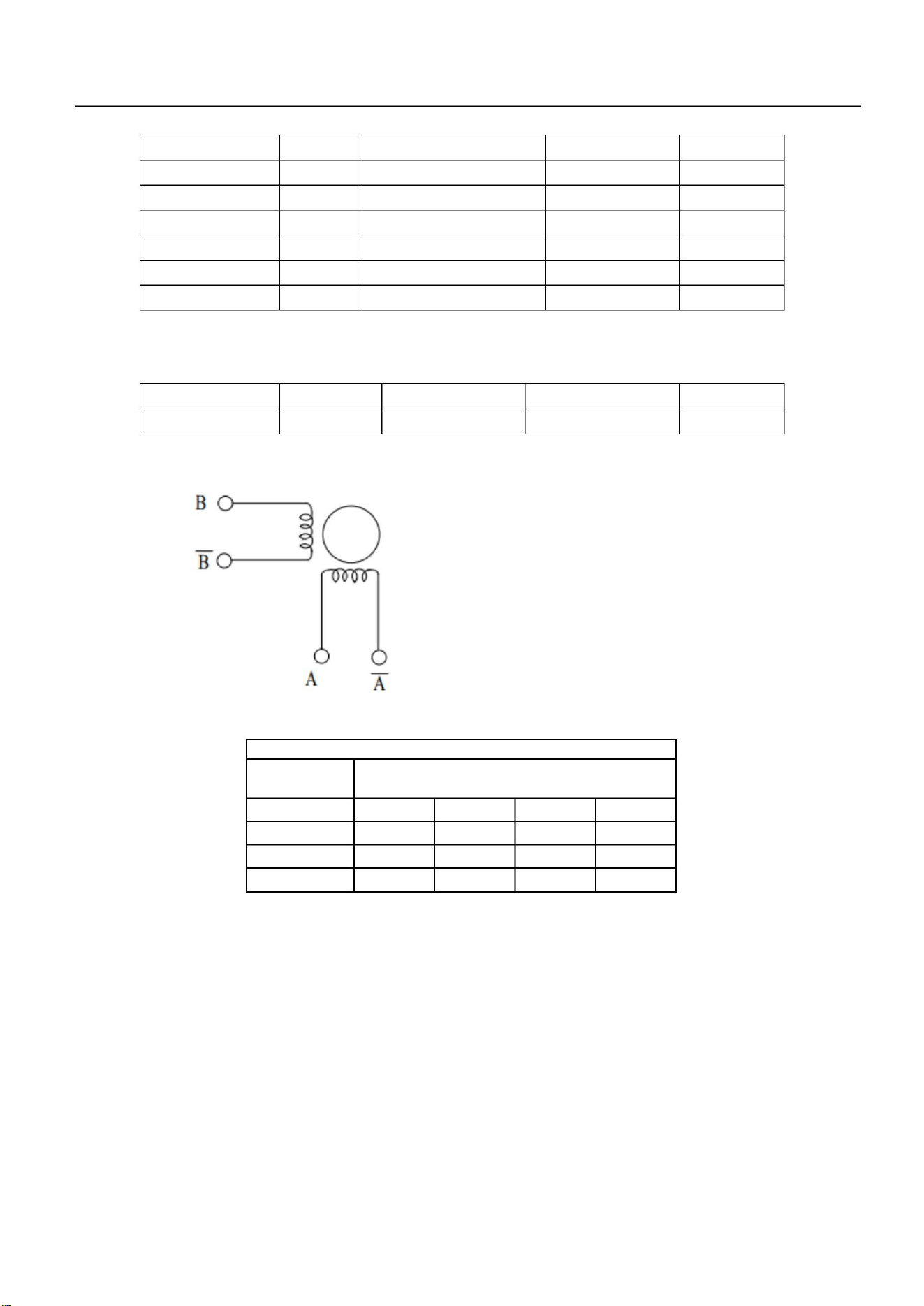
Step Motor
1,2,3,4
Winding resistance(at25℃):A→A- 415±10%Ω
B→B- 415±10%Ω
CW Rotation
Houling No
COLOR
STEP
4--Blue
+
+
-
-
+
+
-
-
-
+
-
1--Red
3--White
2--Yellow
+
+
-
-
+
Following is the correct pin for PCB and step motor pin:
PCB Pin 1(Black) = Step Motor Pin 4(Blue)- A
PCB Pin 2(Blue)= Step Motor Pin 3(White)- A-
PCB Pin 3(Yellow) = Step Motor Pin 1(Red)- B
PCB Pin 4 (Red)= Step Motor Pin 2(Yellow)- B-
Service manual
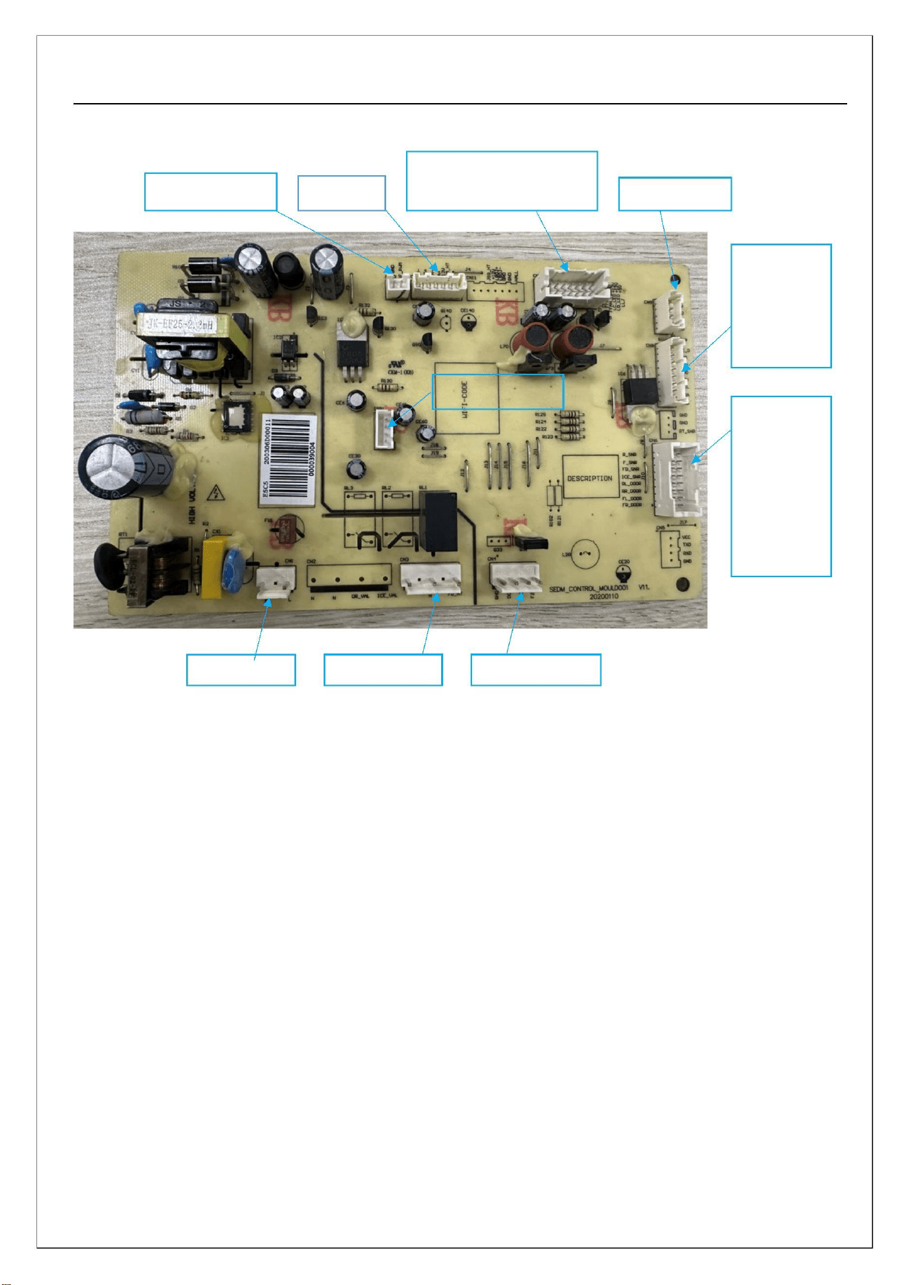
2. Physical diagram of the main control board and definition of interface terminals
Condenser & Freezer Fan
Inverter signal
Damper
LED light
Test program
Display
Temp/Humi
dity senser
Software burning
Fridge/Free
zer/Defrost
sensers
Fridge/freez
er door
switch
Power input
Defrost heater
Flip beam heater
12
Service manual
Chapter 6: Control Principles, Parameters, and Detection Methods
1. Introduction to Refrigerator Control
l) Refrigeration room control: When the refrigeration temperature zone flashes, long press and hold the
"Temperature Zone" selection button for 5s to select whether to turn on or off the refrigeration shutdown
function. The refrigeration shutdown digital display window displays "OF". When the refrigeration is
turned off and the refrigeration temperature zone flashes, long press and hold the "Temperature Zone"
selection button for 5s to restore the refrigeration room function;
2) Freezing room control: When the freezing temperature zone icon flashes, every time the temperature
adjustment button is pressed, the integer digit in the digital display area flashes. Repeating this button
can adjust the integer digit. When the integer digit flashes, pressing the OK button switches to the
decimal digit flashing to set the decimal digit. At this time, pressing the OK button or 5S will
automatically complete the temperature setting, and the icon will stop flashing;
3) Quick freezing control: Press the mode button to cycle through intelligent, quick freezing, quick
freezing/quick cooling, quick cooling, and no mode. No button operation takes effect for 10 seconds;
4) Quick cooling control: Press the mode button to cycle through the selection of intelligent, quick
freezing, quick freezing/quick cooling, quick cooling, and no mode. It takes 10 seconds for no button
operation to take effect;
5) Intelligent control: Press the mode button to cycle through the selection of intelligent, quick freezing,
quick freezing/cooling, quick cooling, and no mode. The operation takes effect for 10 seconds after no
button is pressed;
6) Door opening alarm: When the refrigerator door is opened for 60 seconds, the display panel buzzer
sounds three times every 30 seconds.
7) Refrigeration lighting control: When the refrigeration room door is opened, the refrigeration room
lighting lights up; Close the door of the refrigeration room, turn off the lighting in the refrigeration room,
and the refrigeration light is the same as above;
8) Fan control:
8.1 If one of the following conditions is met, the refrigeration room fan motor is turned on:
a. (When the compressor is turned on in a non defrosting state) AND (the doors of the refrigeration
13
Service manual
room and freezer are closed);
b. (When the compressor is turned off in a non defrosting state and refrigeration is requested) AND
(when the doors of the refrigeration room and freezer are closed).
Note: If cooling is called for, the evaporator fan will run after 10 min delay once door is closed.
8.2 If one of the following conditions is met, the evaporator fan motor stops:
a. The compressor is shut down and the refrigeration is not in a refrigeration state;
b. Frozen chamber /defrosting status;
c. Either door is opened (if the door is opened for more than 4 hours, it will return to its original state)
Note: Evap fan speeds, Low = 7.8V, Med (Normal) = 9.2V, Hi = 12V/ Cond fan single spd = 12V;
9) Damper control
9.1 If one of the following conditions is met, the air door of the refrigeration room is closed:
a. Refrigeration room is at or below the selected temperature;
b. During the defrosting process;
c. The refrigeration room is closed;
9.2 When the following conditions are met, the air door of the refrigeration room is opened:
a. (Non defrosting process) AND (Non refrigerated shutdown mode) AND (Tra ≥ Trk);
b. After 17 minutes of defrosting exit, the compressor meets the startup conditions or requests
refrigeration for refrigeration;
9.3 Abnormal control of damper status (accumulated 60 minutes only after power on and refrigeration
reaches the shutdown point once)
a. Keep the air door open for 60 minutes and reset the air door once;
b. The damper is continuously closed for 60 minutes and the damper is reset once;
9.4 Control of damper heater
a. Within 6 hours of power on, the heating wire of the air door should remain on;
b. No door opening action for 6 hours, and the heating wire of the damper is closed;
10) Display control: No button operation (last operation shall prevail), lock after 20 seconds, display
screen when the refrigerator or freezer door is opened Illuminated (only one door signal is detected at a
time)
14
Service manual
11) Compressor protection: The compressor can only be restarted after every 7 minutes of shutdown,
and normal control of the compressor can only be entered after the 7-minute delay has ended;
2. Test program
The time accuracy during the self inspection process is not used as a basis for determining whether the
software function is qualified or not, in order to detect whether the hardware circuit can work.
When powered on, press and hold the "Temperature"+"Function" buttons 1 time to enter the
testing mode, and all refrigeration loads will run;
When powered on, press and hold "Temperature"+"Function" 2 times (defrosting sensor
temperature below 5 degrees Celsius) to start defrosting operation;
Detect each temperature input port, and if it is abnormal, the temperature display area will
cycle to display fault codes;
When powered on, press and hold "Temperature"+"Function" 3 times to return to normal
operation mode;
15
Service manual
Chapter 7: Refrigeration Principle and Pipeline Cycle Diagram
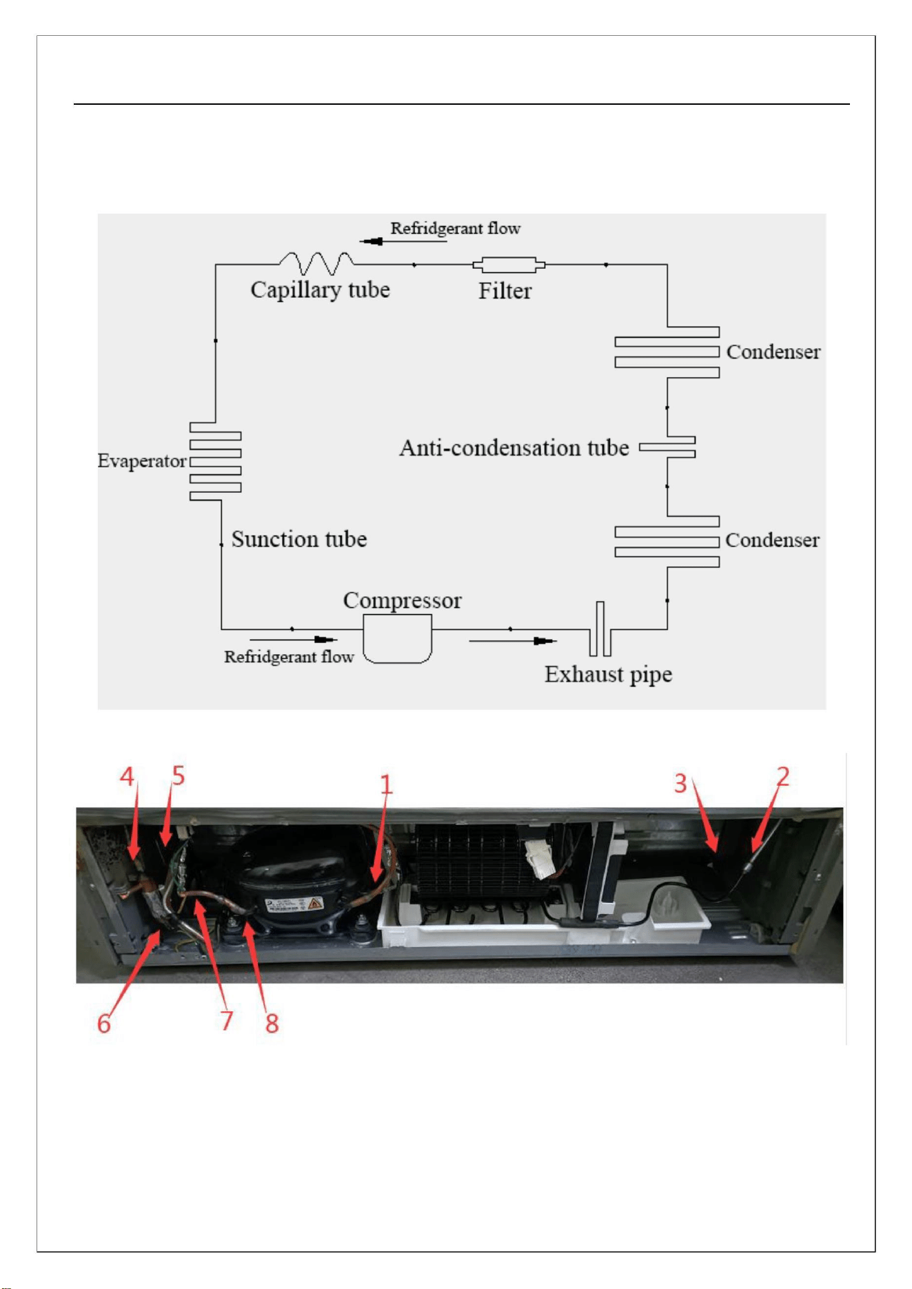
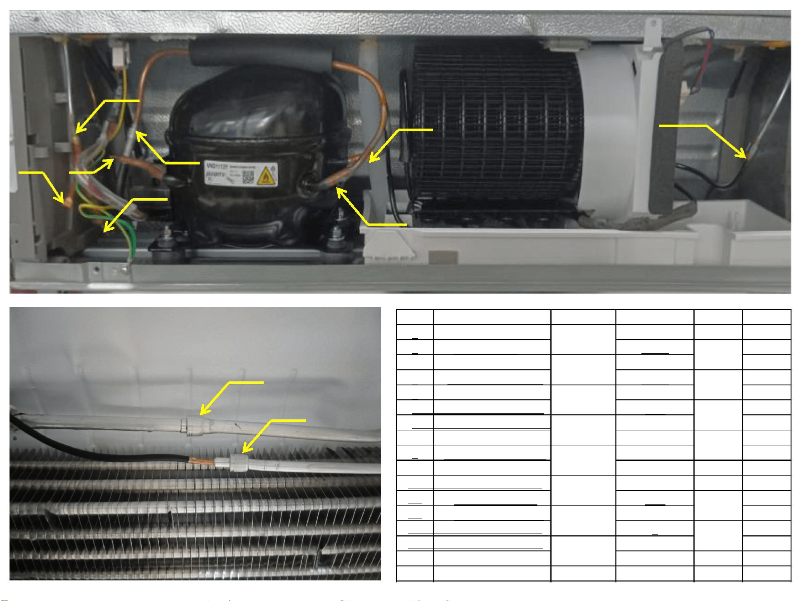
1. Refrigeration system schematic diagram:
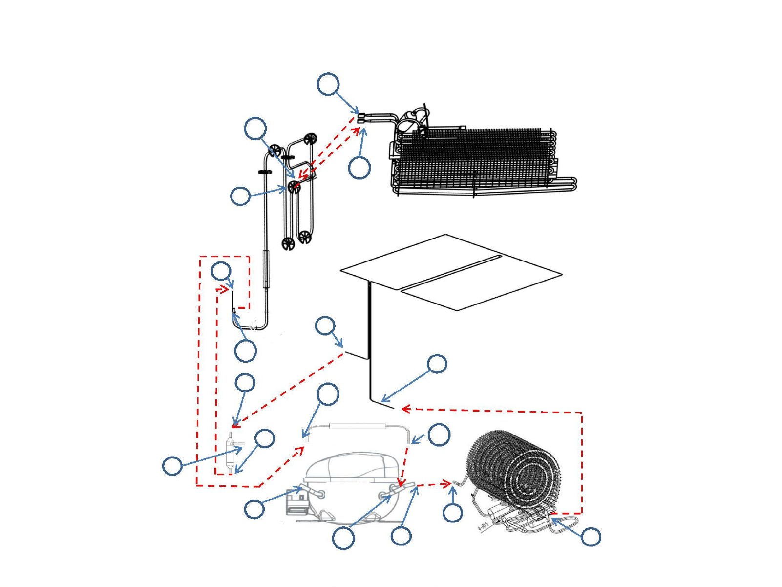
2. Pipeline circulation diagram: solder joint distribution
Compressor - Solder point l (brazing) - Exhaust connecting pipe - Solder point 2 (circumferential
welding) - Left condenser- Solder point 3 (circumferential welding) - Anti dew pipe - Solder point 4
(circumferential welding)- Right condenser- Solder point 5 (brazing)- Drying filter- Solder point 6
(brazing)- Capillary tube- Return pipe- Solder point 7 (circumferential welding)- Compressor suction
pipe - Solder point 8 (brazing)- Compressor
16
Refrigerant circuit connection
11
12
10
9
8
5
13
4
6
14
15
7
B
A
2
1
3
16
5/6
3/4
1/2
13/14
7/8
B
A
15/16
key Pipe part name Pipe
φ .mm
thickness remark
1
2
3
4
5
comp disch port
cond inlet
cond outlet
anti-cond inlet
anti-cond outlet
4.9
4.76
4.95
4.76
4.76
4.9
2.2
2
/
Copper
0.6
0.65
0.75
/
11/12
9/10
Lockring
Copper
Copper
6 dry filter inlet
7 dry filter outlet
8
9
10 evaprator inlet
11 evaprator outlet
12
13
14 Over pipe inlet
15 Over pipe outlet
16
A+B
capillary inlet
capillary outlet
2
Ring weld
3.15
8.2
8.2
6.2
6
6
6.2
6
1.2
0.75
Ring weld
Ring weld
suction inlet
suction outlet
1
0.75
Copper
comp inlet
/
0.75
process pipeline
ultrasonic
Service manual
Chapter 8: Disassembly Instructions for Main Components
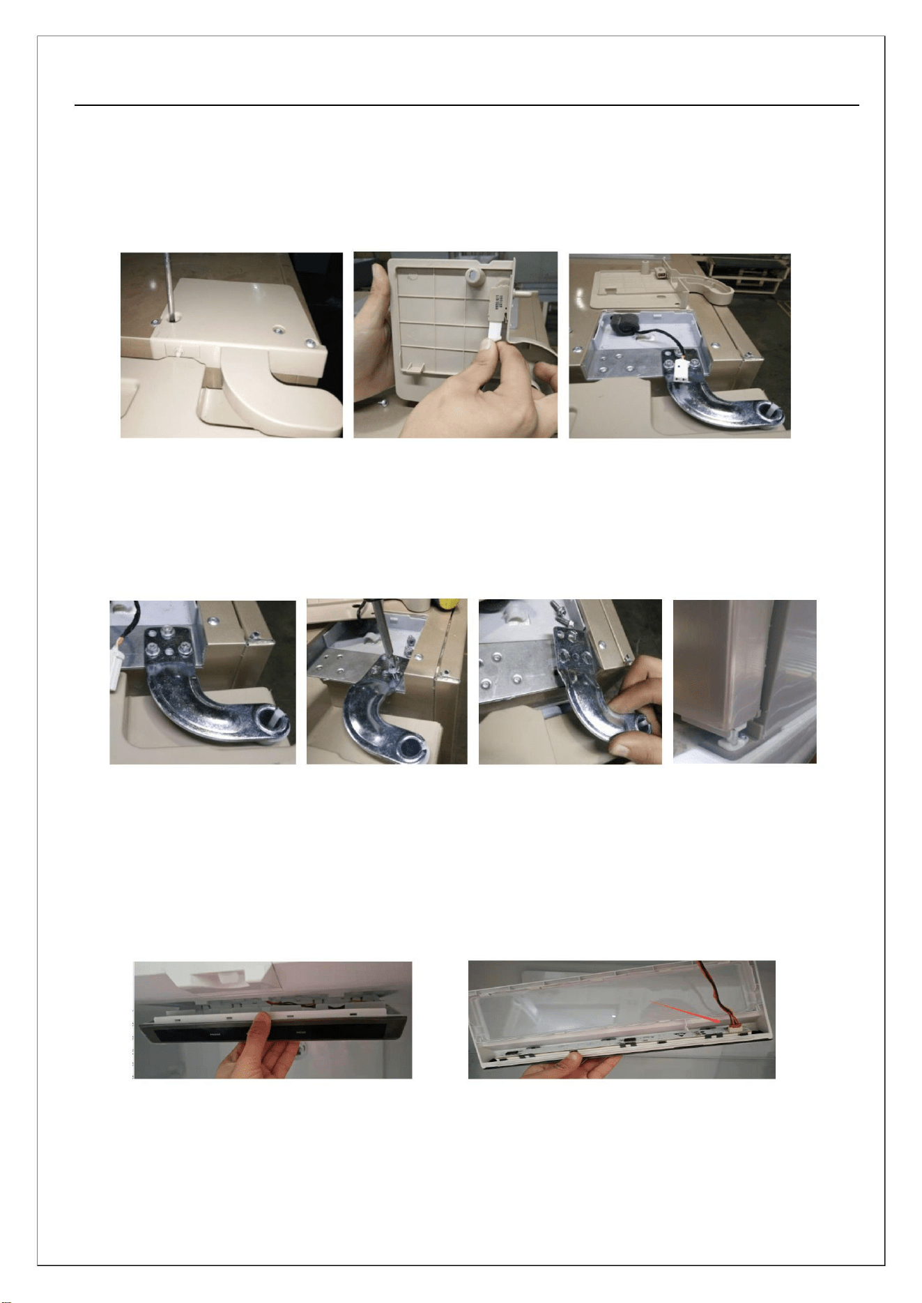
1. Door disassembly
1) Remove the upper hinge cover
a, Use a simple Phillips screwdriver to remove the upper hinge cover screws;
b, Unplug the door lamp switch terminal (hold the terminal head with your hand and pull it out as shown
in Figure 2);
2) Remove the upper hinge
a, Remove the upper hinge screws and use a simple ring gun/wrench/6mm internal diameter socket
wrench;
b, Detach the upper hinge from the cabinet;
c, Lift the door upwards to complete the disassembly of the door.
1. Disassemble display and control board components
17
Service manual
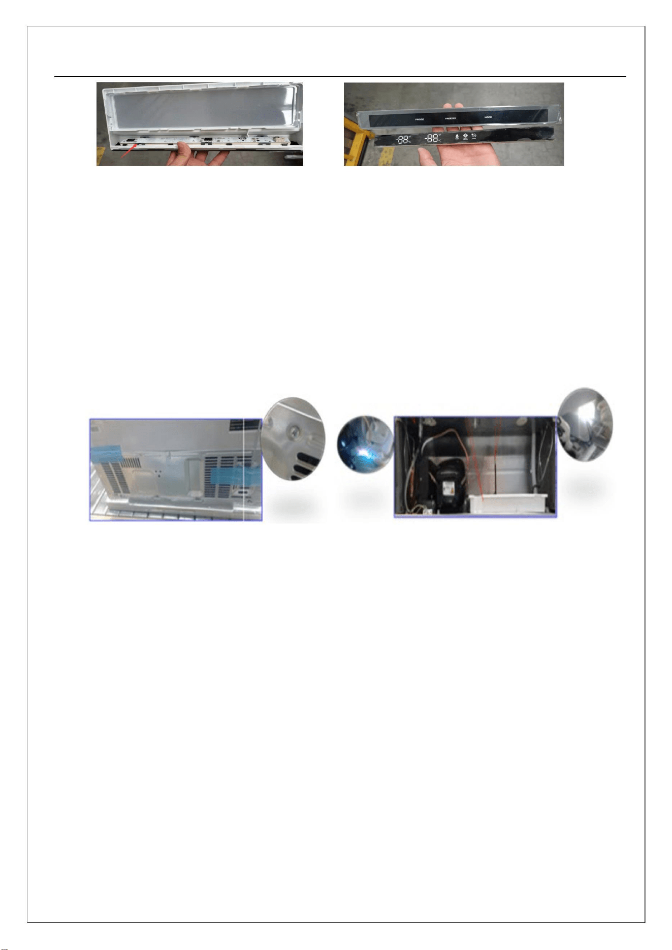
a, Hold the front of the lampshade with your hand, which is one end of the display panel lamination
component, and pull it down forcefully to remove the lampshade;
b, Disconnect the display board connection wire inside the lampshade;
c, Hold the buckle of the display panel lamination component with your hand, and press firmly inside
the box to remove the display panel and the lamination component as a whole from the lampshade;
d, Similarly, hold the buckle of the display panel lamination component with your hand, and press
firmly inside the box to separate the display panel and lamination component;
2. Disassemble compressor components
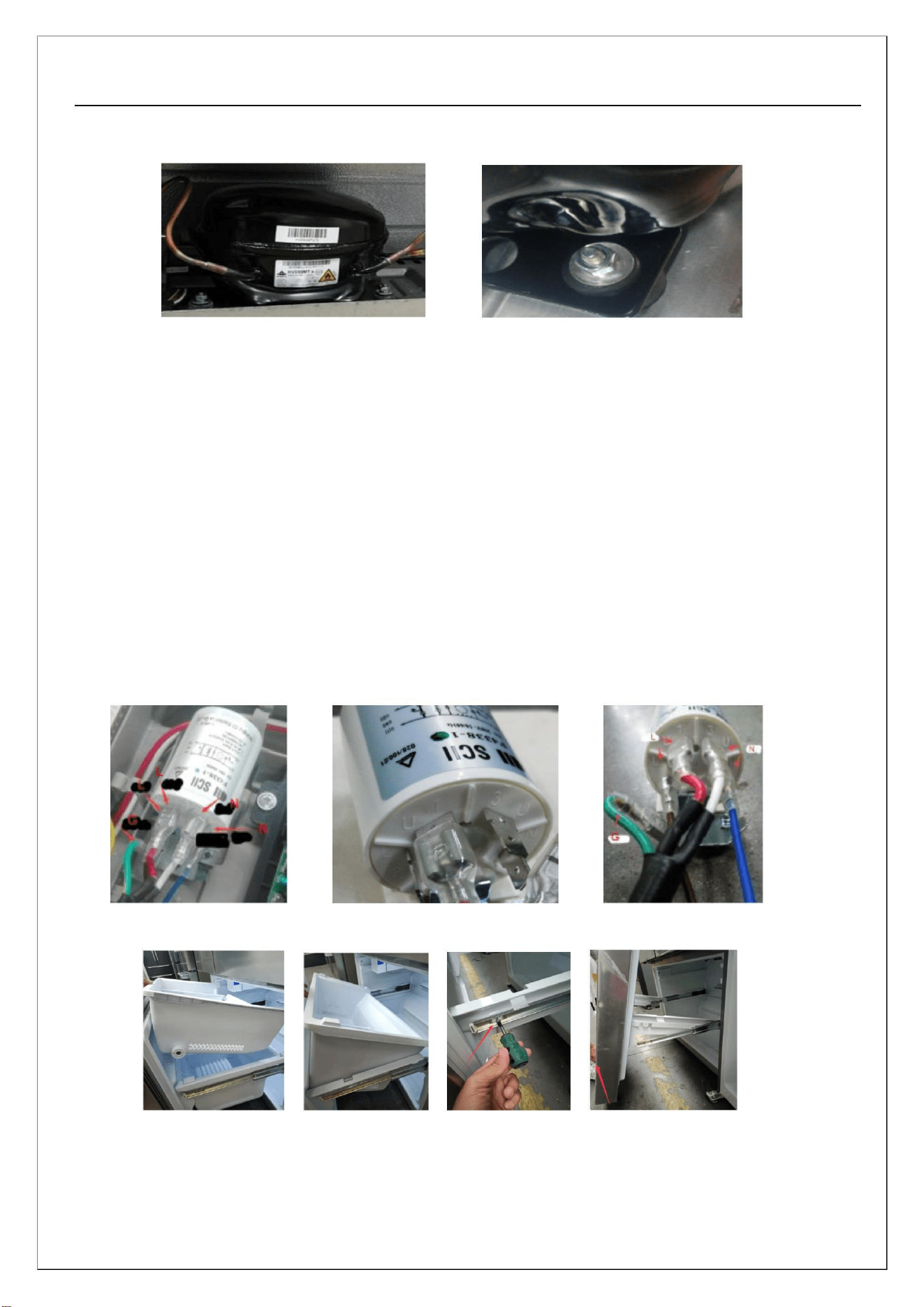
1) Disassemble the rear cover plate of the compressor: Use a Phillips screwdriver to remove the screws;
2) Disassembling the compressor assembly:
Warning: Refrigerant R600 is a flammable and explosive gas, which requires professional refrigerator
maintenance personnel to operate during the maintenance process.
18
Service manual
Technician R600a Sealed System Repair Guide
The following is in addition to or serves as a reminder of the established and prescribed company service
procedures for R600a sealed system diagnosis & repair.
1. This refrigerator contains flammable refrigerant. Follow all relative company, federal,
and local safety guidelines.
2. No torch or heat gun is to be used on or near any product charged with flammable refrigerant.
3. When the service request indicates a possible sealed system issue, the product and
service area must be tested for combustible vapor using an approved combustible gas
detector prior to and during servicing the sealed system.
4. Communicate with consumer concerning flammable refrigerant precautions.
5. Do not apply power to the compressor terminals with the protective cover removed.
6. Unless a technician is certified and equipped for R600a sealed system repair, the sealed
system must be diagnosed without system entry or access.
7. All sealed system connection points (joints) must be analyzed before ordering parts to ensure that all
connections can be completed.
8. Dry-powder class C fire extinguisher is nearby and accessible.
9. The service area must be well ventilated.
10. The product is grounded during repair to prevent static electrical spark.
11. Using proper equipment, temporarily recover the system to the deepest level possible while shaking the
compressor periodically.
12. Bring the system vacuum to atmospheric pressure using regulated dry oxygen-free
nitrogen or if leak testing is needed, pressurize up the low-side design pressure.
13. If not leak testing and system at atmospheric pressure, purge the system with dry
nitrogen following prescribed procedure steps then cut all necessary connections using
tubing cutter and cap-tube cutter.
14. Replace all needed sealed system components, leaving the filter-drier replacement for last.
15. Pressure test using dry oxygen-free nitrogen at no greater than low-side design pressure.
16. Safely expel the nitrogen from the system.
17. Complete the deep evacuation process and recharge using virgin R600a refrigerant
following the prescribed method.
18. Cap off and test access ports for leakage.
19. Add red color to access ports tubing following AHAM guideline.
20. Vent outdoors the recovered and unused R600a refrigerant following the prescribed method.
18
Service manual
3) Removing the compressor
Use a wrench to remove the fixing screws, and remove the remaining 4 in sequence
4) Replacement of inverter product components:
a, The filter interface has a total of 5 interfaces, with L2\N4 being the input terminal for inserting power
lines. U1\U3 is the output terminal, and the main control board is powered by plugging in the filter
connection line;
b, Among them, L2 and Ul are the live wire, N4 and U3 are sporadic. Please note that the plug-in wires
should not be confused, and matching terminals must be inserted according to the color, otherwise a
short circuit may occur and the power line may be burned;
c, The plug-in diagram is shown in the following figure
3. Disassemble freezer door drawer
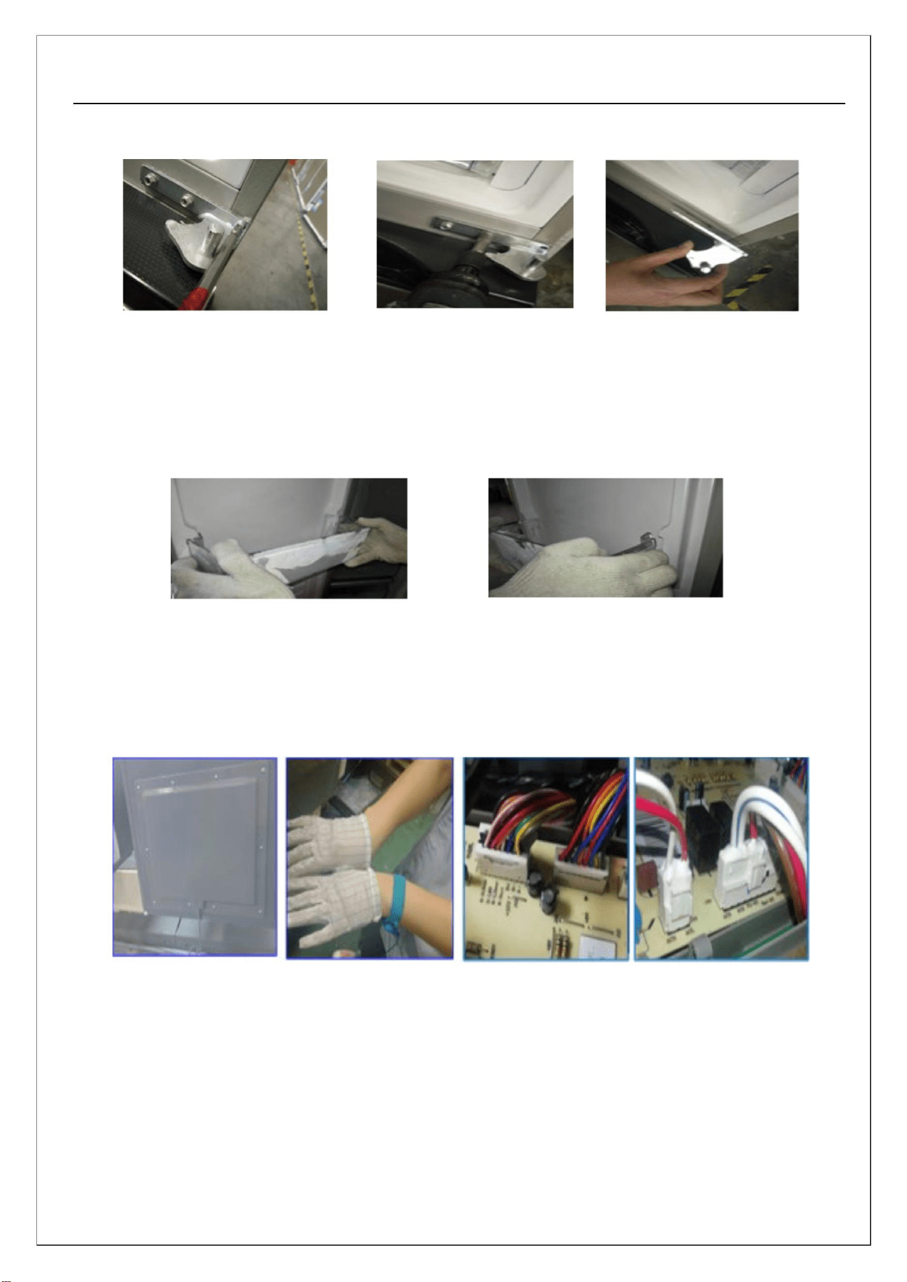
1) Manually remove the drawer from the freezer;
2) Manually remove the drawer under the freezer;
3) Use a Phillips screwdriver to remove the screws that secure the door bracket (l on the left and l on the
19
Service manual
right);
4) Lift up the freezing door from the bottom to remove the door;
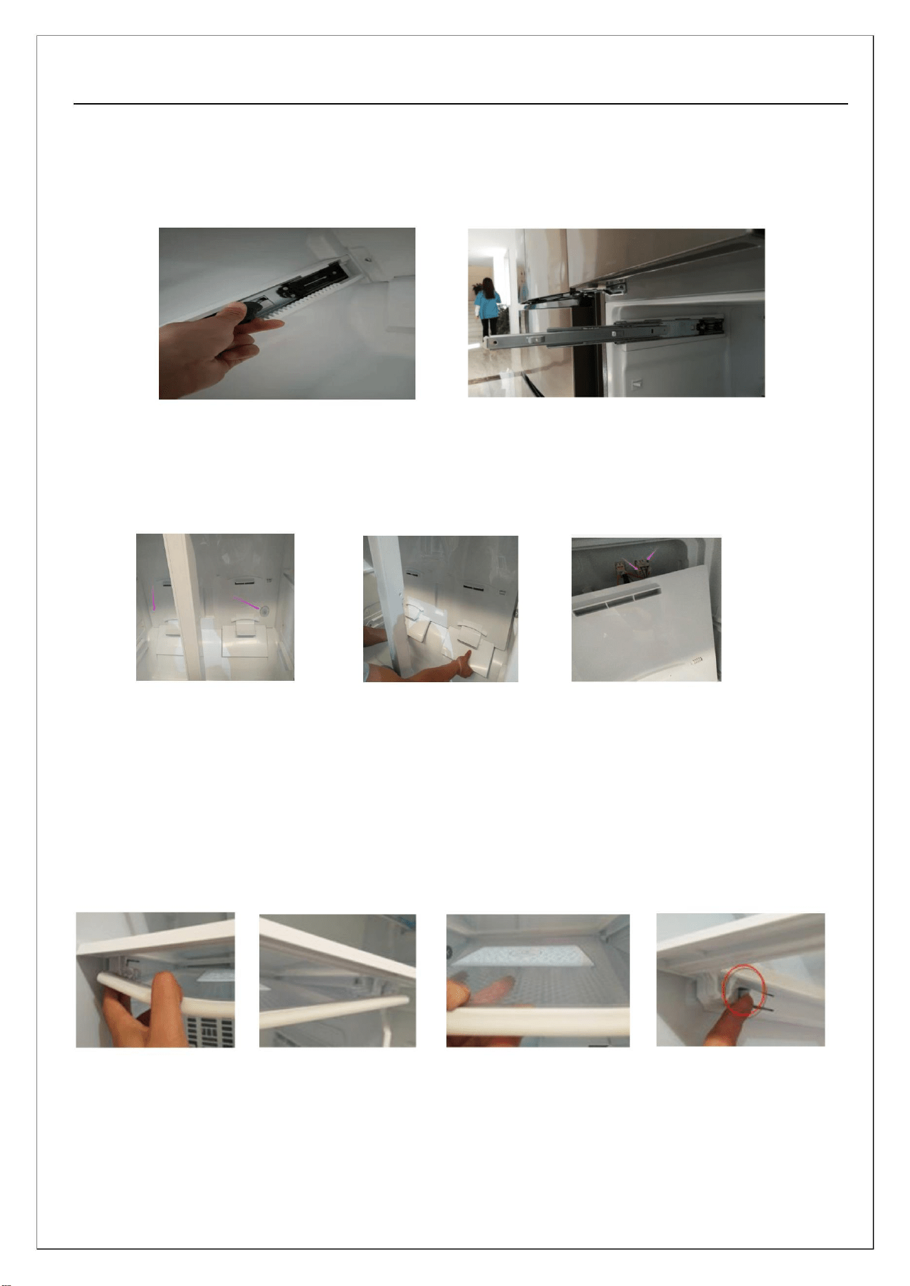
4. Freezer drawer slide and guide rail disassembly
Use a Phillips screwdriver or a flat screwdriver to press the protruding buckle of the rail bracket, and at
the same time, forcefully pull the metal rail outward to remove it
5. Remove the cover of the freezer air duct
1) Place the suction cup in the lower right corner of the air duct, pull it out with force and hear a "click"
sound, and handle it the same way in the lower left corner;
2) Pull both hands on the air outlet and pull out all the clips on both sides, then move downwards until
all the upper clips come off;
3) Press and remove the heater and defrost sensor terminals to remove the air duct;
6. Remove the frame of the fruit and vegetable box
l) Use force on one side to deform the moisturizing cover plate and force downwards to detach one side
of the shaft, while using the same method to snap the other end to detach the shaft;
2) Pull out the moisturizing cover plate for about 40mm to remove it;
3) Gently pull out the frame while opening the front stop spring outwards, handle it the same way on the
20
Service manual
other side, and then pull out the frame outwards;
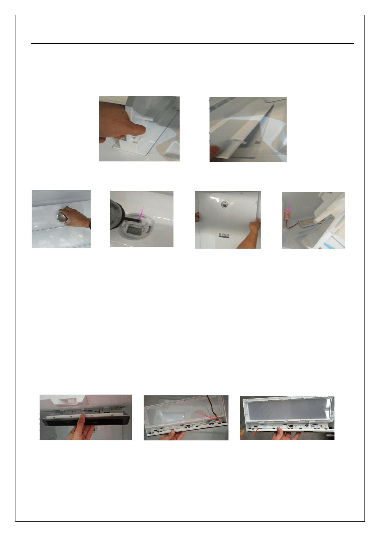
7. Remove the support in the fruit and vegetable box
Clamp the front section and lift it up forcefully;
8. Remove the cover of the fridge air duct
l) Pull out the refrigerated atmosphere lamp shade horizontally and forcefully;
2) Use a screwdriver to unscrew the screw;
3) Grab the upper l/3 of both sides with both hands and apply evenly until the buckle is released. Then
pull the right side until all the buckles are released, then pull the left side until all the buckles are
released, and finally shake slightly to pull out the upper buckle;
4) Remove the sensor terminal connector to complete the disassembly of the air duct cover plate;
Note: The dismantling of the air duct cover requires first dismantling the frame and middle support of
the fruit and vegetable box, and then dismantling them in sequence;
9. Removing the ceiling light of the fridge room
1) Hold the front of the lampshade with your hand, which is one end of the display panel lamination
component, and pull it down forcefully to remove the lampshade;
2) Disconnect the connecting wire of the display board inside the lampshade to cancel the top lampshade
of the refrigeration room;
21
Service manual
10. Middle hinge disassembly
1) Use a Torx to remove the screws fixing the middle cross beam and side plate on the middle hinge;
2) Use a screw driver to remove the fixing screws of the middle hinge;
3) Remove the left and right middle hinges in sequence to complete the disassembly;
11. Removing bottle frame
The bottle frame is directly clamped into the limit position in the door liner. Hold both ends of the bottle
frame with your hand, hold the bottle frame with one hand and hold it still, while squeezing the bottle
frame to one side with the other hand to remove it
12. Disassemble the main control board
1) Use a Torx to remove the screws on the power box cover of the main control board, and then wear
anti-static measures to remove the main control board;
2) After wearing anti-static measures, pull the wiring harness terminals inside the box upwards and
separate them from the main control board;
3) Break the power switch limit claw outward and remove the main control board along the side where it
is broken;
22
Service manual
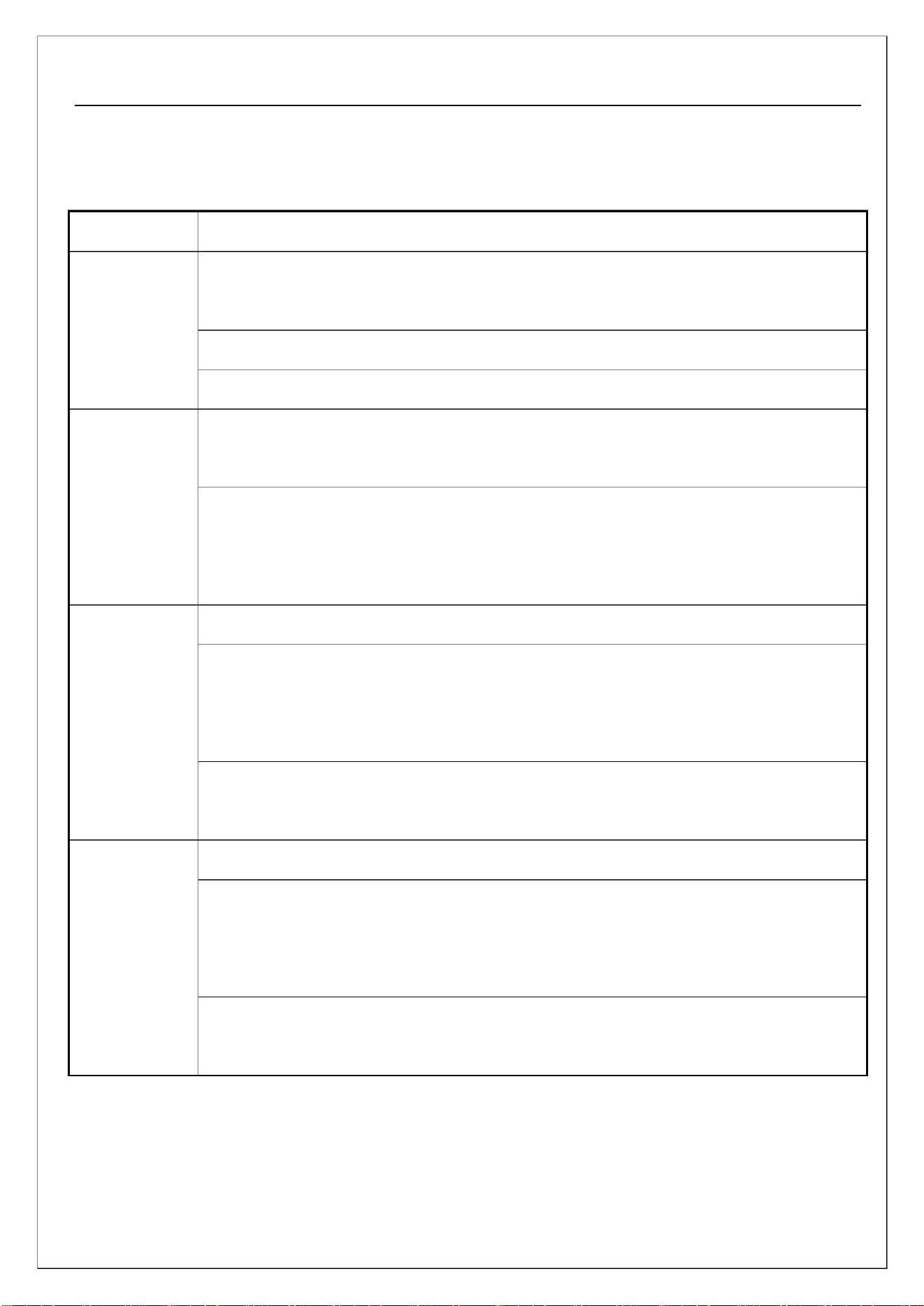
Chapter 9: Typical Fault Diagnosis and Troubleshooting
1. Common faults and troubleshooting of refrigeration systems:
Phenomenon
Fault analysis
Cause 1: The compressor does not start: check whether the inverter board reports an
error and whether the power supply voltage of the main control board is normal
Reason 2: Frequent compressor trips: Check if the frequency converter board is faulty
Reason 3: Is there any blockage in the refrigeration system
Refrigerator
not cooling
Reason 1: Check whether the connectors of the main control board are loose or have
poor contact;
A
certain
room in the
refrigerator is
not cooling
Reason 2: If the refrigeration room does not cool, check whether the refrigeration fan
is running. When checking the refrigeration fan, press the door light switch and check
after 5 seconds;
Reason 1: Check for refrigerant leakage;
Reason 2: Check if each fan is running: Open the door and observe if the air outlet is
discharging. When checking the refrigeration fan, press the door light switch and
check after 5 seconds.
Insufficient
refrigeration in
the refrigerator
Cause 3: Check whether the evaporator in the freezer is severely blocked by frost and
whether defrosting is normal.
Reason 1: Check if the pipelines collide and if the compressor resonates;
Reason 2: Check if the exhaust temperature is too high. If the exhaust pipe temperature
is too high (it should not exceed 60 ℃/140℉ when the ambient temperature is
25 ℃/77℉), there is a possibility of air mixing in the system, causing abnormal noise;
Reason 3: Check if the fan blades of the refrigeration room are interfering with other
components due to abnormal sound from the fan.
Abnormal
noise
23
Service manual
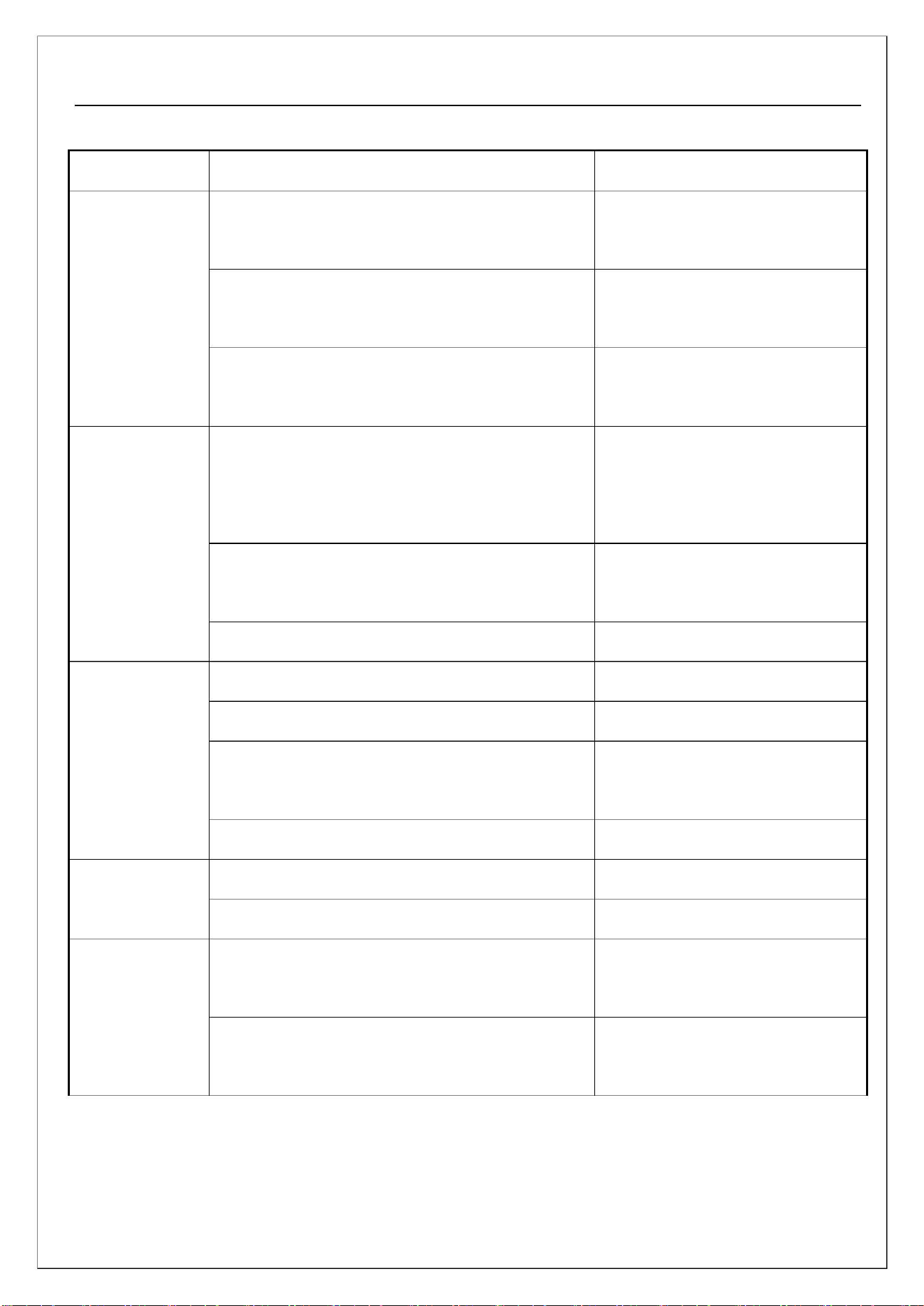
2. Common faults and troubleshooting of electronic control system:
Phenomenon
Possible reasons
Is the power supply connected, the plug firmly
inserted, and the power plug in good contact
The fuse on the main control board has blown
out
Maintenance methods
Connect the power supply or plug
it in or plug in the power plug
Replace the fuse
There is no
display on the
display screen
and the lighting
is not on
Poor contact of the power supply connector on
the main control board
Insert the connector properly
Insert the connector properly
Poor contact at the connector on the signal
harness connecting the display board and the
main control board
No display on
the display
screen and the
lighting is on
There is a broken wire in the signal connection
harness
Repair or replace the wiring
harness
Display and control board failure
Poor contact of compressor plug-in
Main control board failure
Repair or replace
The display
screen shows
normal
Insert the connector properly
Repair or replace
The two components of the compressor are
Repair or replace
compressor not faulty
working
Compressor malfunction
Repair or replace
Repair or replace
Repair or replace
Reinstall and tighten the fan
blades
Fridge room not Electric control board malfunction
cooling
Electric damper failure
The fan blades of the refrigeration room fan
motor have fallen off
Freezer room
not cooling
Refrigeration room fan motor failure
Check the connectors or replace
them
24
Service manual
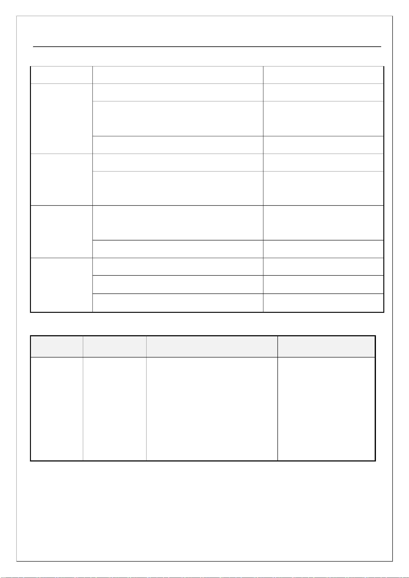
Phenomenon
Possible reasons
Maintenance methods
Blocked return air duct
Clean the return air duct
Check the seal of the
refrigeration/freezing door
replace
Fridge/freezer
frosting
Refrigeration/Freezing Room Leakage
Defrosting heater or sensor malfunction
Severe frost
The defrosting circuit connector has fallen off
Insert the connector properly
replace
formation in the Defrosting heater or sensor malfunction
freezer
Check whether the compressor harness is
Show Reconnect
Compressor not
connected normally
working
Electric control board malfunction
Replace the main control board
Reinstall and adjust the position
Repair or replace
Improper assembly of buttons (springs)
Button
Touch capacitor fault
malfunction
Display and control board failure
Repair or replace
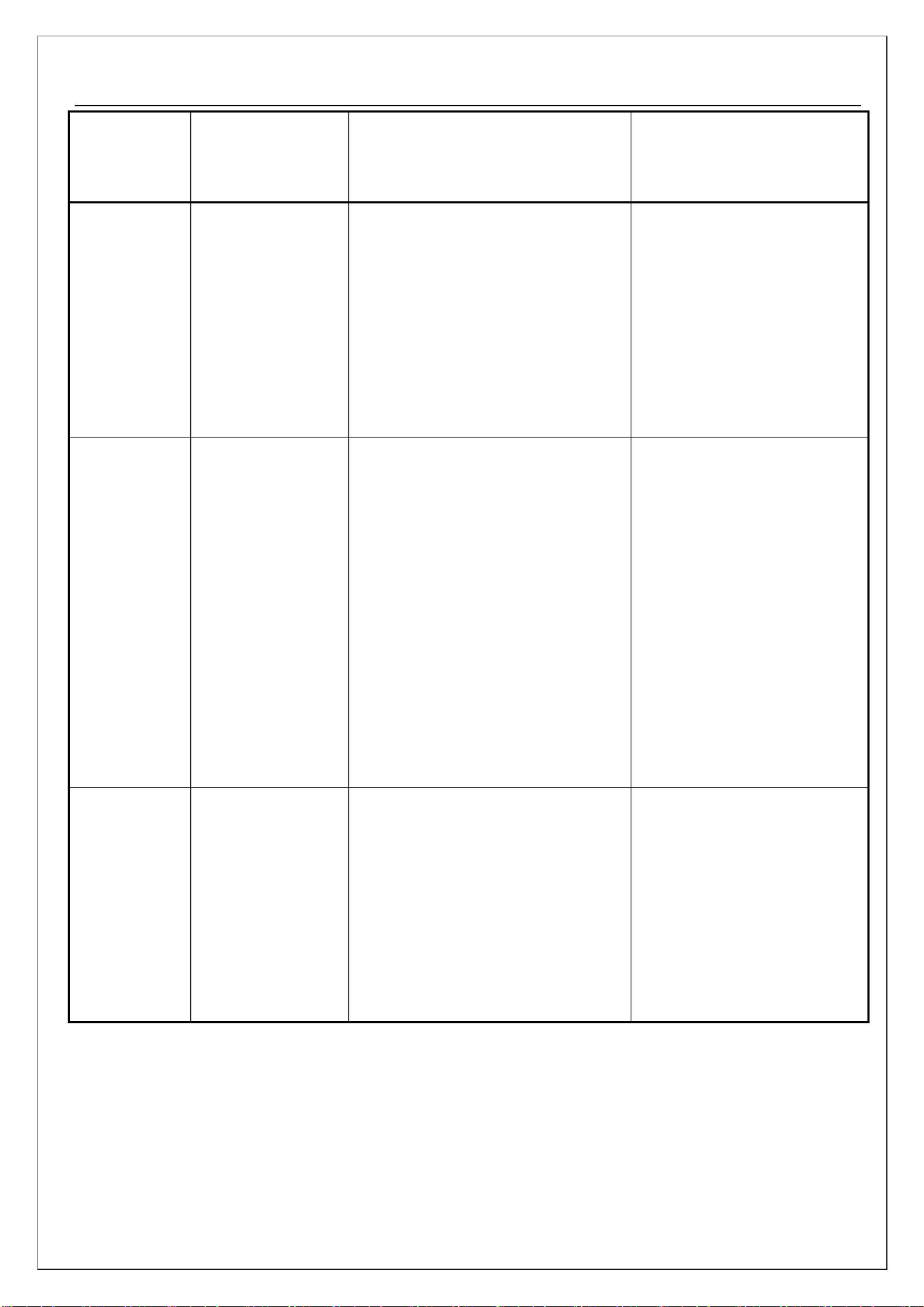
2. Main electrical component failures:
Component
Phenomenon
Test method
Maintenance methods
Test the resistance of the defrosting
heater with a multimeter, with a
resistance value of approximately
252 ohms; Test whether the
Replace the heater due to
heater failure;
With defrosting
action, without
defrosting
Defrosting
heater/fuse
Replace the fuse in case of
fuse failure;
defrosting fuse is in the on state
(multimeter diode is on)
25
Service manual
Component
Phenomenon
Test method
Maintenance methods
In non commodity inspection
mode, set the temperature of the
refrigeration room to 2 ℃/35.6℉
and manually check whether there
is air outlet at the air duct of the
refrigeration room
Check whether the harness
interface of air door is
normal; Replace the main
control panel, otherwise
replace the damper
Damper
Fridge not cooling
1. Check if the connector is
properly connected
2. Check whether the lamp on the
mainboard is powered normally
Light
The light is not on 3. If all lights are off, check the
door light switch and
communication line
4. Some lamp beads do not light
up, replace the lamp board
The cooling in the
Main board failure, replace
the main board, and reinstall
the fan due to rotor blockage
freezer is slow,
and the
Check if the main board
refrigeration fan terminal is
Fan motors
Note- When the fridge fan
malfunctions, the electric damper
closes and the refrigerator does not
cool.
temperature in the powered on and if the fan is
freezer cannot
drop
blocked
4. Fault sign and maintenance
When the following failures appear on the display, it means that the refrigerator is malfunctioning.
In some failures, the refrigerator can still be cooled, but perform maintenance as soon as possible to
realize the optimal operation of the refrigerator.
26
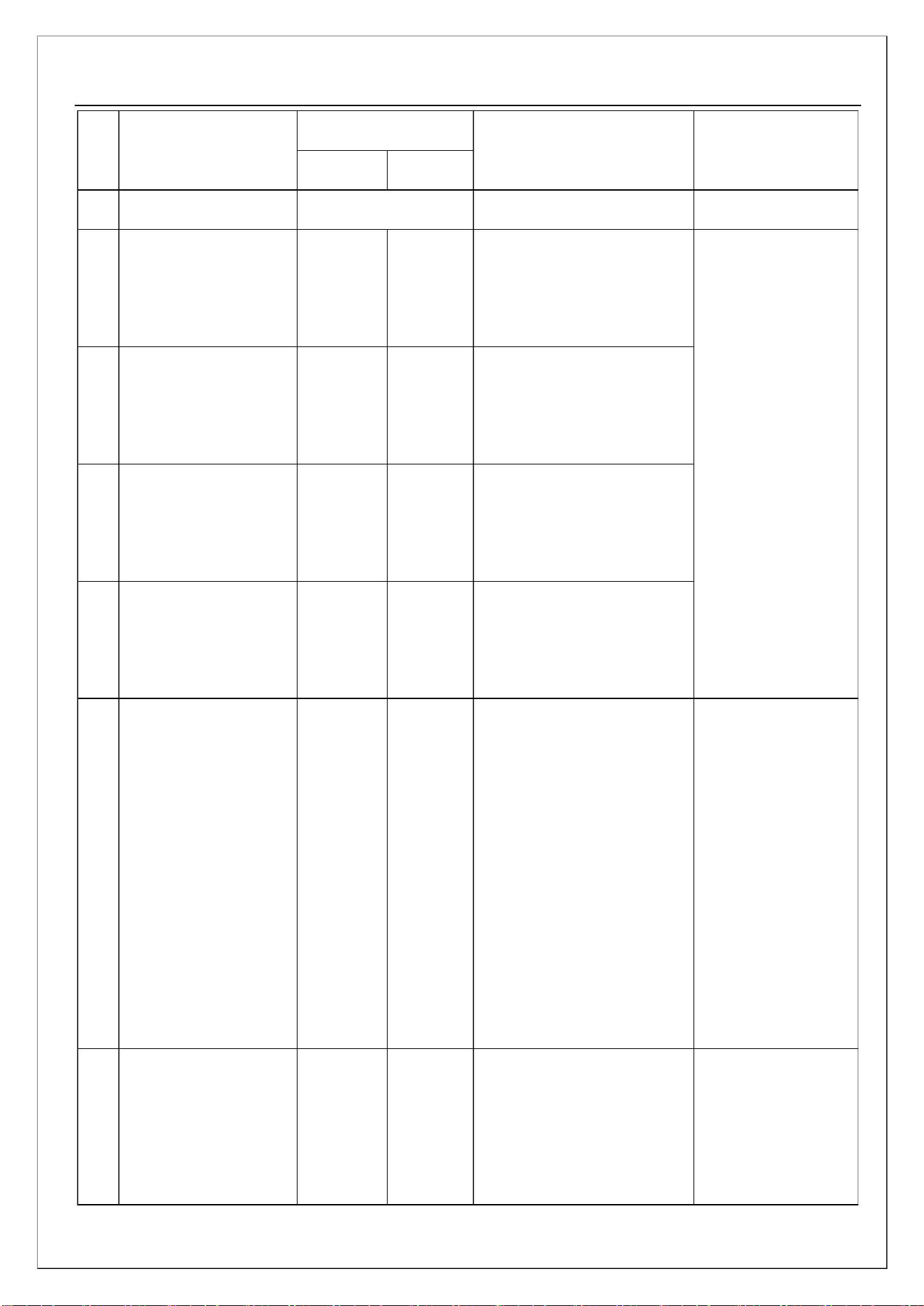
Item
Service manual
Fault sign
Freezer Fridge
As per setting
Default details
Remark
1
2
normal
-
Display normally
Freezing sensor
disconnected or
short-circuited
Freezing sensor
abnormal
FS
rH
rS
Er
Er
Er
Er
Sensor wiring
check
Ambient temperature
sensor disconnected or
short-circuited
Ambient temperature
sensor is abnormal
3
4
5
Note- When the
fridge, freezer, and
defrosting sensors
fail, the compressor
operates according to
a certain start stop
ratio.
Refrigeration sensor
disconnected or
short-circuited
Cold storage sensor
abnormal
Defrost sensor is
disconnected or
short-circuited
Defrost sensor
abnormal
dS
The temperature
protector is
disconnected, the
heater is
Start defrosting. After 70
minutes, the defrosting and
defrosting sensor is below
5℃/41℉
6
Poor defrosting
dH
Er
disconnected, the
drain pipe is
blocked, and the
heater relay is
defective
Communication between
control board processor
and display board
processor
Abnormal
communication
transmission
Communication
abnormal
7
CO
Er
27
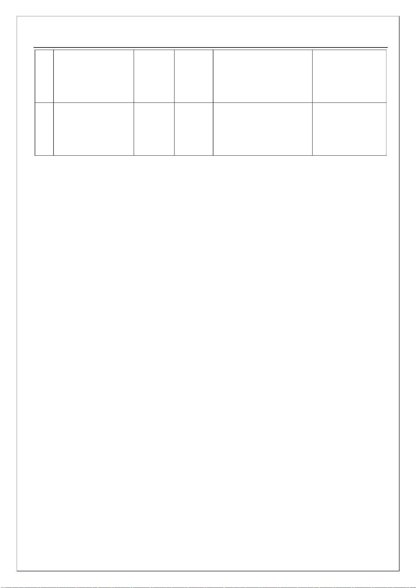
Service manual
When the motor runs for
more than 30 seconds and
there is no feedback signal
When the motor runs for
more than 30 seconds and
there is no feedback signal
Defects in motor
wiring, Drive IC,
TR, etc.
Abnormal freezing
8
FF
Er
Er
motor
Defects in motor
wiring, Drive IC,
TR, etc.
Condensing motor
9
CF
abnormal
28