150W SIREN AMPLIFIER
WITH PTT MICROPHONE
INSTRUCTION MANUAL
ALL YYATYS PRODUCTS COME WITH PREMIUM AFTER-SALES SUPPORT.
IN THE UNLIKELY EVENT OF ANY PRODUCT ISSUES, WE OFFER A FULL REFUND
OR REPLACEMENT – YOUR SATISFACTION IS GUARANTEED.
IMPORTANT: READ CAREFULLY BEFORE ASSEMBLY AND USE.
Installer of this product must have a good understanding of automotive electronics,
systems, and procedures.
DANGER!
In the case that holes must be drilled in order to properly mount the product, the installer
must examine both sides of the mounting surface before drilling begins. It is the installer's
responsibility to be sure that no vehicle components or vital parts could be damaged by the
drilling process. De-burr any holes in order to remove metal shards and remnants. Use
grommets in all wire passage holes.
Do not attempt to activate or operate this product under hazardous driving situations.
Never operate the siren indoors or in an enclosed area.
Deployment area of the vehicle air bags must be cleared. Do not install this product or
route any electrical wires near the air bags deployment areas. Refer to your vehicle
owner's manual for the air bag deployment area. Products or wires mounted in the air bag
deployment area will damage, reduce the effectiveness of the air bag, or even act as a
projectile which may cause serious injury or death. The user/installer of this product
assumes full responsibility in determining the proper mounting location while prioritizing
the safety of all passengers in the vehicle.
SAE J1849 recommends that the maximum sound pressure level in the passenger area,
with the vehicle in motion and the siren active, should not exceed 85 dB.
Sirens are designed to produce extremely loud emergency warning tones! Exposure to
the tones produced without proper and adequate hearing protections, could lead to ear
damage and/or hearing loss! The Occupational Safety & Health Administration
(www.osha.gov) provides information necessary to determine safe exposure times in
Occupational Noise Exposure Section 1910.95. The operators of the siren and any one in
the immediate vicinity of the siren should be required to wear an approved hearing
protection device until one has determined the safe exposure times for your specific
application.
FAILURE TO FOLLOW THIS RECOMMENDATION COULD CAUSE HEARING LOSS!
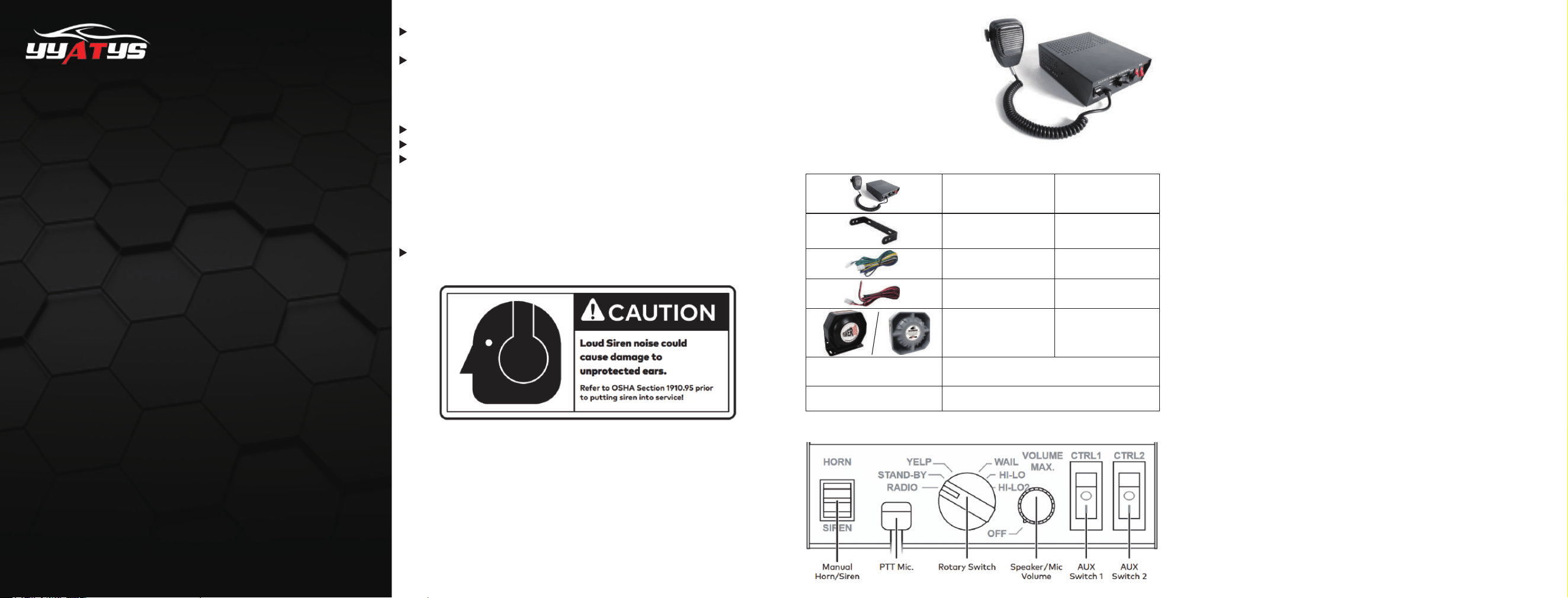
Specifications:
Contents:
Input Voltage: 12V DC
Input Current: 15 Amps
Speaker Impedance: 8 Ohms Min.
Power rating: 150 Watts
Frequency: 400 - 4,000 Hz
Sound Compression Level: 120 – 130 dB
1
Bail Strap Bracket
Siren with PTT Mic.
Wiring Bundle
Wiring for Battery
Siren Speaker
1
1
1
1
1
1
Mounting Accessories
Fuse(s)
Functions:
Manual Horn/Siren
This switch has two positions. Down - Siren & Up- Horn. The siren and horn warning tone
could be activated manually by engaging the switch to the positions. Horn function can also
be activated with the vehicle horn relay by connecting the horn/radio wire of the siren unit to
the horn relay of the automobile. (see wiring diagram)
PTT Mic
Push to talk microphone which overrides any activated warning tone when in use.
Rotary Switch
The rotary knob controls siren functions. There are 5 positions that may be selected.
(see switch functions below for detail)
Speaker/Mic Volume
The volume knob controls the volume of siren and public address function. Rotating the
knob clockwise will increase the volume. Rotating the knob counter-clockwise will decrease
the volume. Rotating the knob to minimal volume will disable all siren functions.
The auxiliary switches are meant to be used to power other equipment on the vehicle. Each
auxiliary switch is fused with a 20 amp AGC fuse.
Aux Switch 1 & 2
Switch Functions:
Optional
− Radio
With the rotary knob set to this function, the radio function would be activated. Any signal
that is received by the vehicle's two-way radio will be broadcasted over the connected
speaker. (the siren must be connected to the two-way radio as outlined in wiring section of
this manual)
− Stand-by
− Horn Override
− Yelp - Activates Yelp warning tone.
− Wail - Activates Wail warning tone.
− Hi-Lo - Activates Hi-Lo warning tone.
− Hi-Lo 2 - Activates Hi-Lo 2 warning tone.
With the rotary knob set to this function, the siren will be in stand-by. Manual Horn/Siren
and PTT Mic functions are enabled during stand-by.
This function, if used, will always be active when the siren unit is on. When it’s active, the
stock steering wheel horn button will trigger the air horn instead of the stock horn. When the
siren unit is turned off, the steering wheel horn button will once again trigger the stock horn.
(the siren must be connected to the stock horn wiring as outlined in the wiring section of
this manual)
− Radio Bypass
The siren must be connected to the two-way radio as outlined in wiring section of this
manual.
WARRANTY
Thank you for purchasing our products!
We insist on customer first, and always help solve the problem, which can improve
our service and the quality of the product, to meet customers' demands.
Strong technical strength and perfect customer service system are
assured to guarantee the purchase and usage.
We offer 3 years warranty. Any problems with the products just contact us on Amazon,
or send us the email, or contact us on FB, we provide REPLACEMENT or REFUND
services, plz purchase with confidence
f
YYATYS
- Be careful and always consult the manufacturer’s wiring diagrams when
looking for, and cutting, the horn wire. Often, the wiring for the airbags, turn signals, and
windshield wipers will be in the same area. Cutting the wrong wire can cause serious damage
to your vehicle.
Mounting:
The siren Is designed to be mounted directly onto the dash or any other surface around the
driver's vicinity using the included bail-strap mounting bracket. The siren unit can also be
mounted into the vehicle's console when vehicle is equipped with such a compartment.
Siren Amplifier and Microphone Clip
− All speakers should be installed facing forward, parallel to the ground, and as far forward
on the vehicle as is possible.
− Keep in mind that the effectiveness of the siren system will be reduced if objects (grille,
push bar, bumper) are in front of the siren speaker.
1. Verify siren amplifier (150W/8Ω) matches speaker specifications.
Wiring the Horn Override Function
CAUTION
- When deciding where to cut the horn wire, choose a location that gives you enough
room to comfortably work in, leaves several inches of free wire on either side of the cut, and
is easy to re-access if repairs or adjustments are needed.
TIP
- In addition to the general wiring suggestions mentioned above, always try to leave
a few inches of slack when running new wires. This puts less stress on the wiring and leaves
room for adjustments and mistakes. The excess can be cut off when making the final
connections.
TIP
1. Locate the wire running from your steering wheel horn button to your vehicle’s horn relay.
2. Choose a location to cut the horn wire.
3.Locate the secondary harness (two blue, black and white wires) that will be plugged into
the back of the siren unit.
6.Cut the horn wire.
7.Using your preferred method, connect the white wire to the cut half of the wire coming
from the stock steering wheel horn button.
8.Connect the black wire to the cut half of the wire going to the vehicle’s horn relay.
9.Plug the wiring harness into the back of the siren unit.
10.Test the horn override feature.
11.As necessary, clean up and secure the wiring with zip ties, wire loom, etc.
12.Reattach any vehicle panels or parts that may have been removed to access the wiring.
4.If the harness is plugged into the siren unit, remove it at this time.
5.Run the black&white wires from the back of the siren unit to the location where the factory
horn wire will be cut.
Speaker
2. Position bail strap, mark drill holes with scribe.
3. Drill and secure with provided screws.
4. Attach siren to bail strap using screws and washer.
5. Position clip, mark drill holes.
6. Drill and secure with screws.
Wiring the Rebroadcast Feature
NOTE: − Because of the numerous different types, manufacturers, and models of two-way
radios it would be impossible to list every wiring option. Below is a simple guide that will work
for most radios. Feel free to adjust it to fit your specific situation and setup.
NOTE: - The goal in this step is not to replace the existing speaker but to run the siren unit
in parallel with the speaker, borrowing a signal from the speaker wires.
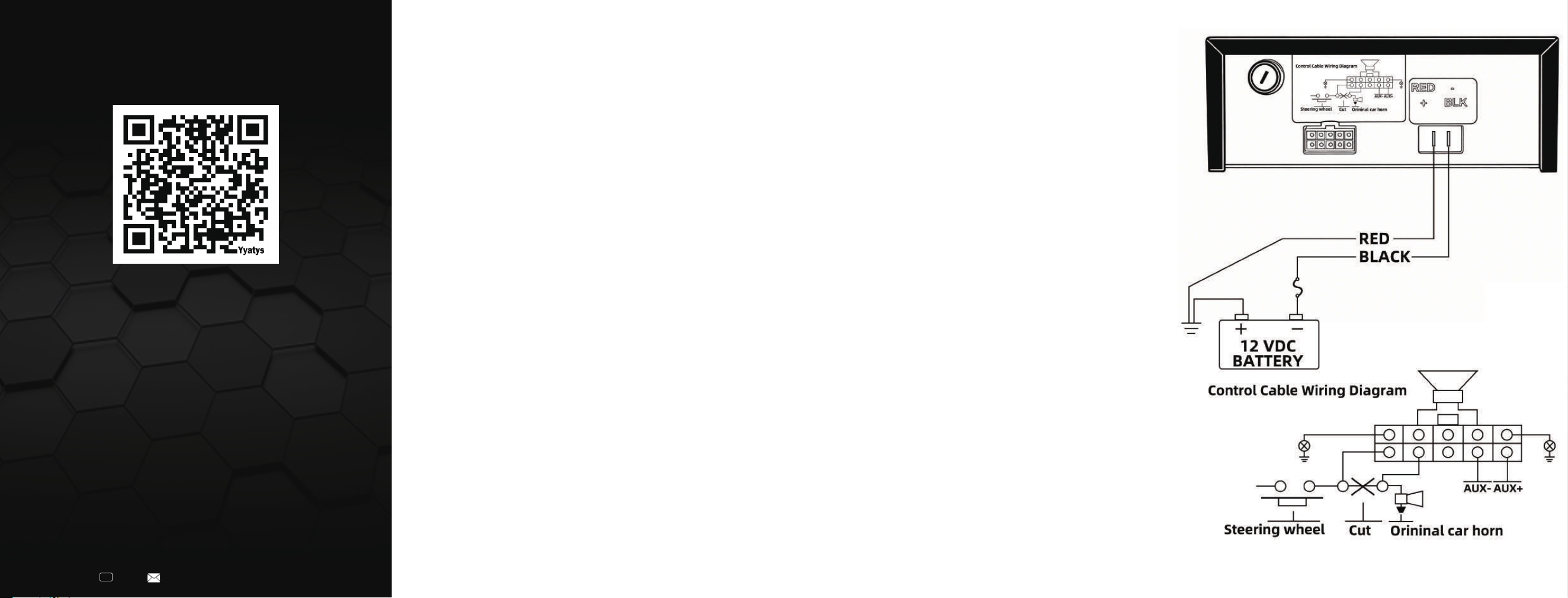
Wiring:
WARNING! All customer supplied wires that connect to the positive terminal of the battery
must be sized to supply at least 125% of the maximum operating current and FUSED at the
battery to carry that load. DO NOT USE CIRCUIT BREAKERS WITH THIS PRODUCT!
Optional Connections:
Horn Connector (Black&White) – Connect the unit in-line between the horn button and horn
relay with the outer white wire connected to the horn button, and the inner black wire
connected to the horn relay.
Radio Connector (BLUE) – Connect the unit in-line between one of the radio’s output wire.
The unit will broadcast the radio in mono sound type. Should only be spliced into one of the
output wires (left or right).
RED- To 12V Power Source BLACK-To Chassis Ground
YELLOW 1-To optional equipment 1 YELLOW 2 - To optional equipment 2
GREEN 1-To speaker GREEN 2-To speaker
- This can happen right at the two-way radio, somewhere along the length of the
speaker wires, or right at the speaker.
TIP
1. Locate the positive and negative wire running from your two-way radio to the radio’s
external speaker.
2. Locate the point where it will be easiest to splice the blue wires into the speaker wires.
3. Locate the secondary harness (two blue, black and white wires) that will be plugged into
the back of the siren unit.
5. Run the two blue wires from the back of the siren unit to the location where the speaker
wires will be spliced.
6. Using your preferred method splice one blue wire into the positive speaker wire.
7. Splice the second blue wire into the negative speaker wire.
8. Plug the wiring harness into the back of the siren unit.
10. As necessary, clean up and secure the wiring with zip ties, wire loom, etc.
11. Reattach any vehicle panels or parts that may have been removed to access the wiring.
9. Test the radio rebroadcast feature. The volume of the sound can be adjusted via the
potentiometer located at the back of the siren unit.
4. If the harness is plugged into the siren unit, remove it at this time.
Wiring Diagram:

FCC Warning
This device complies with Part 15 of the FCC Rules. Operation is subject to the following two conditions:
(1) This device may not cause harmful interference, and (2) this device must accept any interference received, including
interference that may cause undesired operation.
NOTE 1: This equipment has been tested and found to comply with the limits for a Class B digital device, pursuant to part 15 of
the FCC Rules. These limits are designed to provide reasonable protection against harmful interference in a residential
installation. This equipment generates, uses and can radiate radio frequency energy and, if not installed and used in accordance
with the instructions, may cause harmful interference to radio communications. However, there is no guarantee that
interference will not occur in a particular installation. If this equipment does cause harmful interference to radio or television
reception, which can be determined by turning the equipment off and on, the user is encouraged to try to correct the
interference by one or more of the following measures:
- Reorient or relocate the receiving antenna.
- Increase the separation between the equipment and receiver.
- Connect the equipment into an outlet on a circuit different
from that to which the receiver is connected.
-Consult the dealer or an experienced radio/TV technician for help.
NOTE 2: Any changes or modifications to this unit not expressly approved by the party responsible for
compliance could void the user's authority to operate the equipment.