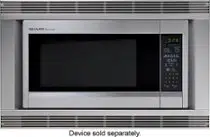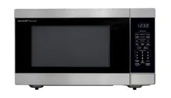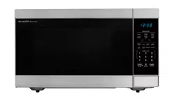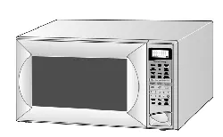
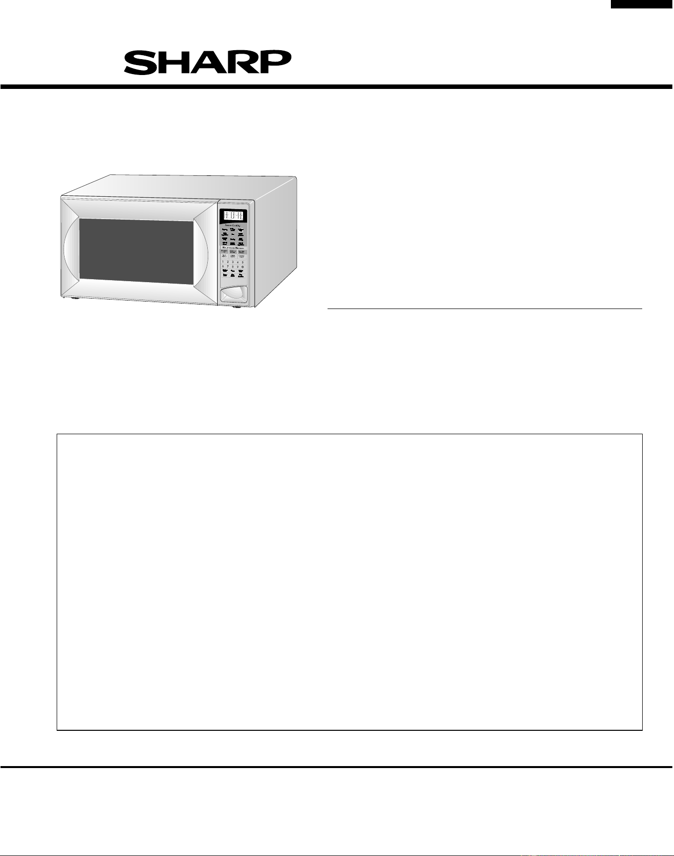
R-519CK
R-530CK
R-530CW
In the interest of user-safety the oven should be restored to its original
condition and only parts identical to those specified should be used.
WARNING TO SERVICE PERSONNEL: Microwave ovens con-
tain circuitry capable of producing very high voltage and
current. Contact with the following parts may result in a severe,
possibly fatal, electrical shock. (High Voltage Capacitor, High
Voltage Power Transformer, Magnetron, High Voltage Recti-
fier Assembly, High Voltage Harness etc..)
TABLE OF CONTENTS
Page
PRECAUTIONS TO BE OBSERVED BEFORE AND DURING SERVICING TO
AVOID POSSIBLE EXPOSURE TO EXCESSIVE MICROWAVE ENERGY ...................INSIDE FRONT COVER
BEFORE SERVICING ......................................................................................................INSIDE FRONT COVER
WARNING TO SERVICE PERSONNEL................................................................................................................ 1
MICROWAVE MEASUREMENT PROCEDURE ................................................................................................... 2
FOREWORD AND WARNING ...............................................................................................................................3
PRODUCT SPECIFICATIONS .............................................................................................................................. 4
GENERAL INFORMATION ...................................................................................................................................4
OPERATION ..........................................................................................................................................................6
TROUBLESHOOTING GUIDE ............................................................................................................................ 10
TEST PROCEDURE ............................................................................................................................................ 12
TOUCH CONTROL PANEL ................................................................................................................................. 21
COMPONENT REPLACEMENT AND ADJUSTMENT PROCEDURE ................................................................ 29
PICTORIAL DIAGRAM ........................................................................................................................................35
POWER UNIT CIRCUIT ...................................................................................................................................... 36
LSI UNIT CIRCUIT ...............................................................................................................................................37
PRINTED WIRING BOARD .................................................................................................................................40
PARTS LIST ........................................................................................................................................................ 41
PACKING AND ACCESSORIES .........................................................................................................................45
S4909R530CUW/
R-519CK
R-530CK
R-530CW
MICROWAVE OVEN
MODELS
SERVICE MANUAL
SHARP CORPORATION
This document has been published to be used for after
sales service only.
The contents are subject to change without notice.
R-530CW
Popcorn
Sensor
reheat
Fresh
vegetables
Kitchen
Timer
Minute
Plus
Power
Level
Clock
Stop
Clear
Start
Touch On
Baked
potatoes
Custom
help
Rice
Ground
meat
Frozen
entrees
Frozen
snacks
Frozen
vegetables
Fish/
seafood
Poultry
SENSOR DEFROST COOK
HELP
Downloaded from www.ManualsFile.com manuals search engine
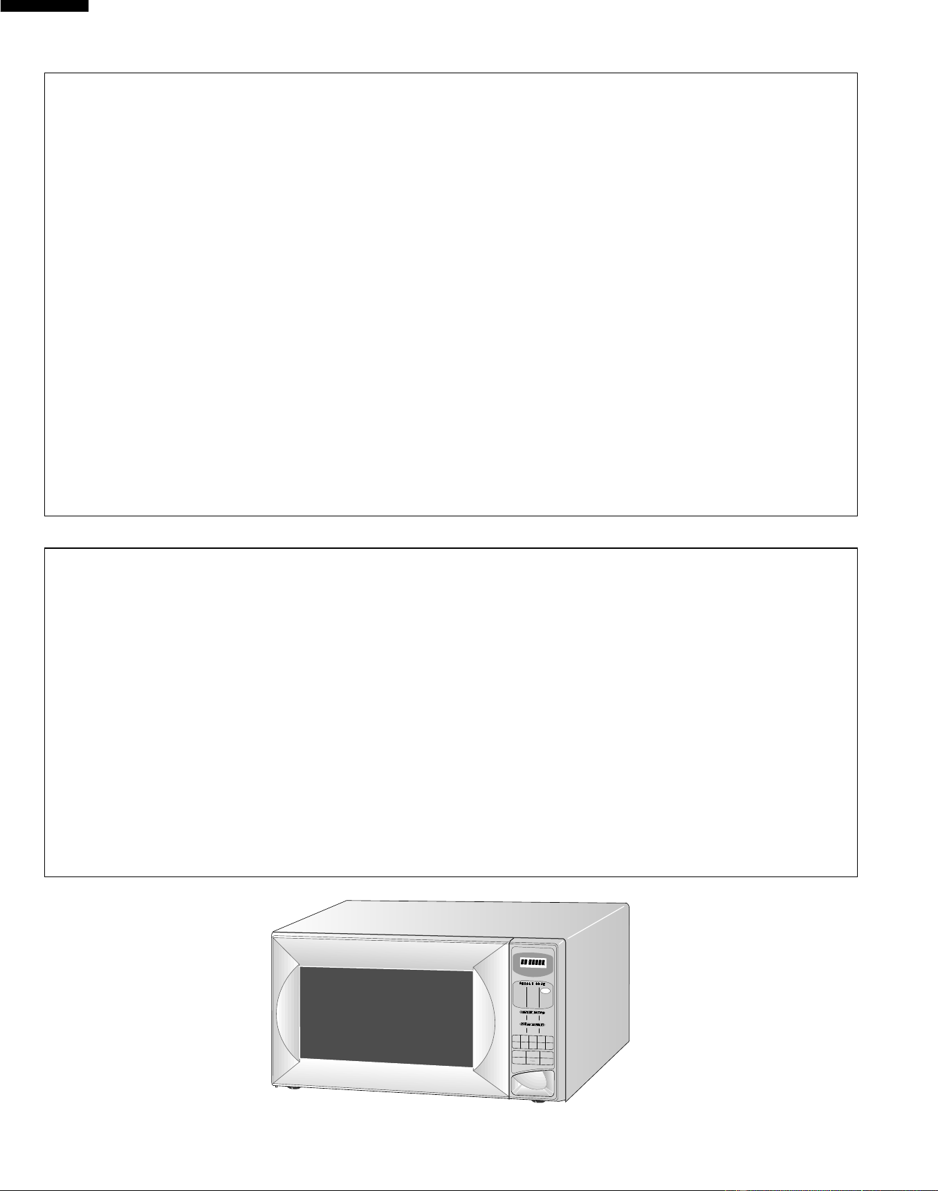
R-519CK
R-530CK
R-530CW
PRECAUTIONS TO BE OBSERVED BEFORE AND
DURING SERVICING TO AVOID POSSIBLE
EXPOSURE TO EXCESSIVE MICROWAVE
ENERGY
(a) Do not operate or allow the oven to be operated with the door open.
(b) Make the following safety checks on all ovens to be serviced before activating the magnetron or other
microwave source, and make repairs as necessary: (1) interlock operation, (2) proper door closing, (3)
seal and sealing surfaces (arcing, wear, and other damage), (4) damage to or loosening of hinges and
latches, (5) evidence of dropping or abuse.
(c) Before turning on microwave power for any service test or inspection within the microwave generating
compartments, check the magnetron, wave guide or transmission line, and cavity for proper alignment,
integrity, and connections.
(d) Any defective or misadjusted components in the interlock, monitor, door seal, and microwave
generation and transmission systems shall be repaired, replaced, or adjusted by procedures described
in this manual before the oven is released to the owner.
(e) A microwave leakage check to verify compliance with the Federal Performance Standard should be
performed on each oven prior to release to the owner.
BEFORE SERVICING
Before servicing an operative unit, perform a microwave emission check as per the Microwave
Measurement Procedure outlined in this service manual.
If microwave emissions level is in excess of the specified limit, contact SHARP ELECTRONICS
CORPORATION immediately @1-800-237-4277.
If the unit operates with the door open, service person should 1) tell the user not to operate the oven
and 2) contact SHARP ELECTRONICS CORPORATION and Food and Drug Administration's
Center for Devices and Radiological Health immediately.
Service personnel should inform SHARP ELECTRONICS CORPORATION of any certified unit found
with emissions in excess of 4mW/cm
2
. The owner of the unit should be instructed not to use the unit
until the oven has been brought into compliance.
R-519CK
Baked
Potatoes
Baked
Potatoes
CUSTOM
HELP
Popcorn
Beverage
Frozen
Vegetables
Ground
Meat
Ground
Meat
Kitchen
Timer
Power
Level
Clock
Stop
Clear
Minute
Plus
START
Steaks/
Chops
Chicken
Pieces
Frozen
Entrees
Fresh
Vegetables
Fresh
Rolls/Muffins
Frozen
Rolls/Muffins
Fish/
Seafood
SENSOR COOK
INSTANT
ACTION
COMPU
DEFROST
12345
6789o
COOK SENSOR LBS KG DEF HELP
Downloaded from www.ManualsFile.com manuals search engine
1
R-519CK
R-530CK
R-530CW
WARNING TO SERVICE PERSONNEL
Microwave ovens contain circuitry capable of pro-
ducing very high voltage and current, contact with
following parts
may result in a severe, possibly
fatal, electrical shock.
(Example)
High Voltage Capacitor, High Voltage Power Trans-
former, Magnetron, High Voltage Rectifier Assem-
bly, High Voltage Harness etc..
Read the Service Manual carefully and follow all
instructions.
Before Servicing
1. Disconnect the power supply cord , and then
remove outer case.
2. Open the door and block it open.
3. Discharge high voltage capacitor.
WARNING:RISK OF ELECTRIC SHOCK.
DISCHARGE THE HIGH-VOLTAGE
CAPACITOR BEFORE SERVICING.
The high-voltage capacitor remains charged about 60
seconds after the oven has been switched off. Wait for 60
seconds and then short-circuit the connection of the high-
voltage capacitor (that is the connecting lead of the high-
voltage rectifier) against the chassis with the use of an
insulated screwdriver.
Whenever troubleshooting is performed the power supply
must be disconnected. It may in, some cases, be necessary
to connect the power supply after the outer case has been
removed, in this event,
1. Disconnect the power supply cord, and then remove
outer case.
2. Open the door and block it open.
3. Discharge high voltage capacitor.
4. Disconnect the leads to the primary of the power
transformer.
5. Ensure that the leads remain isolated from other
components and oven chassis by using insulation tape.
6. After that procedure, reconnect the power supply cord.
When the testing is completed,
1. Disconnect the power supply cord, and then remove
outer case.
2. Open the door and block it open.
3. Discharge high voltage capacitor.
4. Reconnect the leads to the primary of the power
transformer.
5. Reinstall the outer case (cabinet).
6. Reconnect the power supply cord after the outer case is
installed.
7. Run the oven and check all functions.
After repairing
1. Reconnect all leads removed from components during
testing.
2. Reinstall the outer case (cabinet).
3. Reconnect the power supply cord after the outer case is
installed.
4. Run the oven and check all functions.
Microwave ovens should not be run empty. To test for the
presence of microwave energy within a cavity, place a cup
of cold water on the oven turntable, close the door and set
the power to HIGH and set the microwave timer for two (2)
minutes. When the two minutes has elapsed (timer at zero)
carefully check that the water is now hot. If the water
remains cold carry out Before Servicing procedure and re-
examine the connections to the component being tested.
When all service work is completed and the oven is fully
assembled, the microwave power output should be checked
and a microwave leakage test should be carried out.
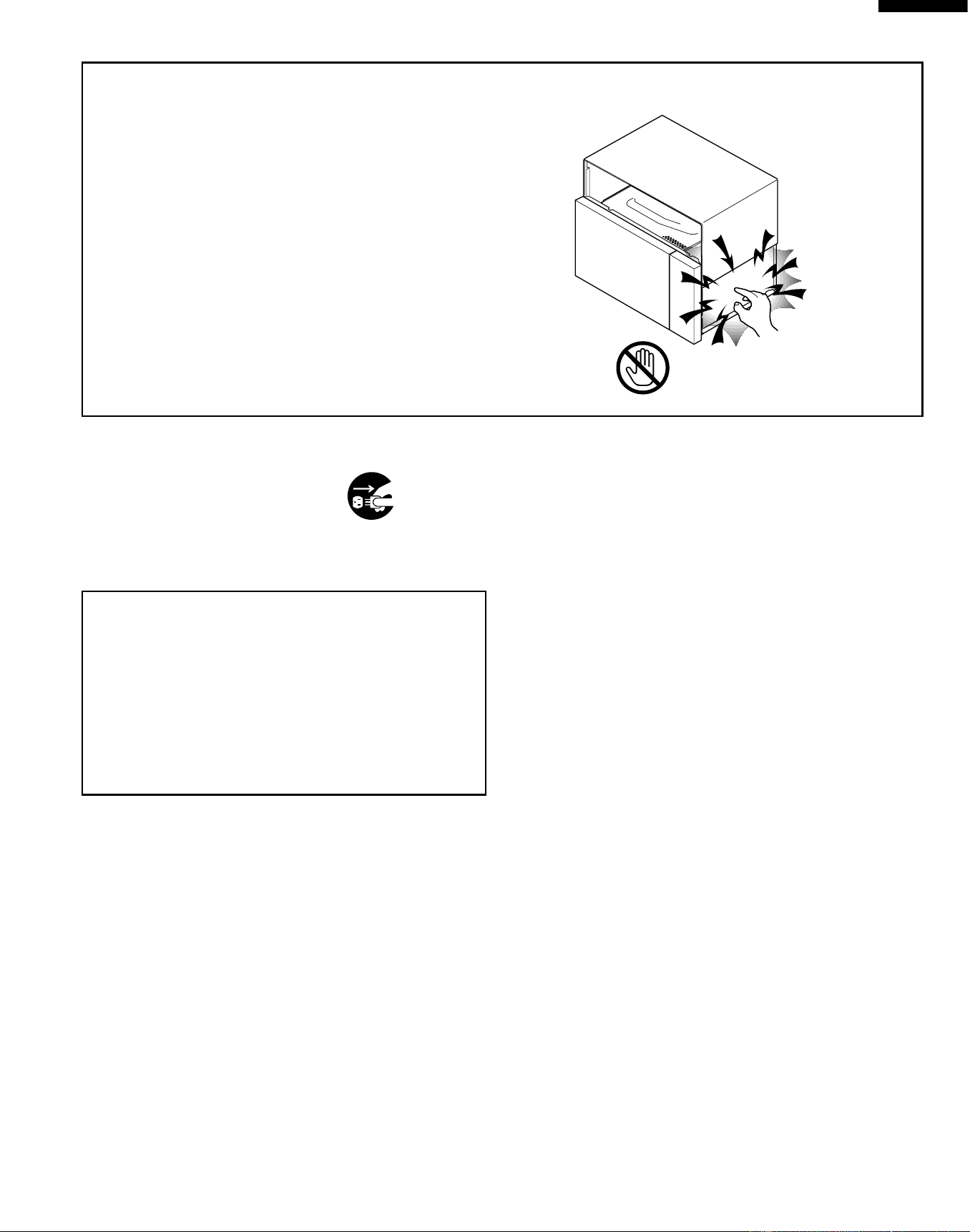
Don't Touch !
Danger High Voltage
Downloaded from www.ManualsFile.com manuals search engine

2
R-519CK
R-530CK
R-530CW
MICROWAVE MEASUREMENT PROCEDURE
A. Requirements:
1) Microwave leakage limit (Power density limit): The power density of microwave radiation emitted by a microwave oven
should not exceed 1mW/cm
2
at any point 5cm or more from the external surface of the oven, measured prior to acquisition
by a purchaser, and thereafter (through the useful life of the oven), 5 mW/cm
2
at any point 5cm or more from the external
surface of the oven.
2) Safety interlock switches Primary interlock relay and door sensing switch shall prevent microwave radiation emission in
excess of the requirement as above mentioned, secondary interlock switch shall prevent microwave radiation emission
in excess of 5 mW/cm
2
at any point 5cm or more from the external surface of the oven.
B. Preparation for testing:
Before beginning the actual measurement of leakage, proceed as follows:
1) Make sure that the actual instrument is operating normally as specified in its instruction booklet.
Important:
Survey instruments that comply with the requirement for instrumentation as prescribed by the performance standard for
microwave ovens, 21 CFR 1030.10(c)(3)(i), must be used for testing.
2) Place the oven tray in the oven cavity.
3) Place the load of 275±15 ml (9.8 oz) of tap water initially at 20±5˚C (68˚F) in the center of the oven cavity.
The water container shall be a low form of 600 ml (20 oz) beaker with an inside diameter of approx. 8.5 cm (3-1/2 in.)
and made of an electrically nonconductive material such as glass or plastic.
The placing of this standard load in the oven is important not only to protect the oven, but also to insure that any leakage
is measured accurately.
4) Set the cooking control on Full Power Cooking Mode.
5) Close the door and select a cook cycle of several minutes. If the water begins to boil before the survey is completed,
replace it with 275 ml of cool water.
C. Leakage test:
Closed-door leakage test (microwave measurement)
1) Grasp the probe of the survey instrument and hold it perpendicular to the gap between the door and the body of the oven.
2) Move the probe slowly, not faster than 1 in./sec. (2.5 cm/sec.) along the gap, watching for the maximum indication on
the meter.
3) Check for leakage at the door screen, sheet metal seams and other accessible positions where the continuity of the metal
has been breached (eg., around the switches, indicator, and vents).
While testing for leakage around the door pull the door away from the front of the oven as far as is permitted by the closed
latch assembly.
4) Measure carefully at the point of highest leakage and make sure that the highest leakage is no greater than 4mW/cm
2
,
and that the secondary interlock switch does turn the oven OFF before any door movement.
NOTE: After servicing, record data on service invoice and microwave leakage report.
Downloaded from www.ManualsFile.com manuals search engine
3
R-519CK
R-530CK
R-530CW
SHARP ELECTRONICS CORPORATION
SHARP PLAZA, MAHWAH,
NEW JERSEY 07430-2135
SERVICE MANUAL
MICROWAVE OVEN
R-519CK/ R-530CK/ R-530CW
FOREWORD
This Manual has been prepared to provide Sharp Electronics Corp.
Service Personnel with Operation and Service Information for the
SHARP MICROWAVE OVEN, R-519CK, R-530CK, R-530CW.
It is recommended that service personnel carefully study the entire
text of this manual so that they will be qualified to render satisfactory
customer service.
Check the interlock switches and the door seal carefully. Special
attention should be given to avoid electrical shock and microwave
radiation hazard.
WARNING
Never operate the oven until the following points are ensured.
(A) The door is tightly closed.
(B) The door brackets and hinges are not defective.
(C) The door packing is not damaged.
(D) The door is not deformed or warped.
(E) There is no other visible damage with the oven.
Servicing and repair work must be carried out only by trained service
personnel.
DANGER
Certain initial parts are intentionally not grounded and present
a risk of electrical shock only during servicing. Service
personnel - Do not contact the following parts while the
appliance is energized;
High Voltage Capacitor, Power Transformer, Magnetron, High
Voltage Rectifier Assembly, High Voltage Harness;
If provided, Vent Hood, Fan assembly, Cooling Fan Motor.
All the parts marked “*” on parts list are used at voltages more than
250V.
Removal of the outer wrap gives access to voltage above 250V.
All the parts marked “∆” on parts list may cause undue microwave
exposure, by themselves, or when they are damaged, loosened
or removed.
PRODUCT DESCRIPTION
GENERAL INFORMATION
OPERATION
TROUBLESHOOTING GUIDE AND
TEST PROCEDURE
TOUCH CONTROL PANEL
COMPONENT REPLACEMENT
AND ADJUSTMENT PROCEDURE
WIRING DIAGRAM
PARTS LIST
Downloaded from www.ManualsFile.com manuals search engine
4
R-519CK
R-530CK
R-530CW
ITEM DESCRIPTION
Power Requirements 120 Volts / 13 Amperes
60 Hertz
Single phase, 3 wire grounded
Power Output 1100 watts (IEC-705 TEST PROCEDURE)
Operating frequency of 2450MHz
Case Dimensions Width 24"
Height 13-3/8"
Depth 19-1/8"
Cooking Cavity Dimensions Width 17-3/8"
Height 10-1/2"
2.0 Cubic Feet Depth 18-5/8"
Control Complement Touch Control System
Clock ( 1:00 - 12:59 )
Timer (0 - 99 min. 99 seconds)
Microwave Power for Variable Cooking
Repetition Rate;
P-HI..................................................Full power throughout the cooking time
P-90 .................................................................... approx. 90% of Full Power
P-80 .................................................................... approx. 80% of Full Power
P-70 .................................................................... approx. 70% of Full Power
P-60 .................................................................... approx. 60% of Full Power
P-50 .................................................................... approx. 50% of Full Power
P-40 .................................................................... approx. 40% of Full Power
P-30 .................................................................... approx. 30% of Full Power
P-20 .................................................................... approx. 20% of Full Power
P-10 .................................................................... approx. 10% of Full Power
P-0 .................................................... No power throughout the cooking time
CUSTOM HELP pad, COMPU DEFROST pads
SENSOR COOK pads, INSTANT ACTION pads
Number selection pads, Kitchen Timer pad, Clock pad,
Minute Plus pad, Power Level pad, Stop/Clear pad, Start pad
Sensor Cooking pads, Breakfast Bar pad, Lunch on the Run pad
One Dish Dinners pad, Super Defrost pad, Compu Defrost pad
Beverage Center pad, Number selection pads, Kitchen Timer pad
Clock pad, Minute Plus pad, Power Level pad, Stop/Clear pad,
Start Touch On pad
Oven Cavity Light Yes
Safety Standard UL Listed FCC Authorized
DHHS Rules, CFR, Title 21, Chapter 1, Subchapter J
SPECIFICATION
GENERAL INFORMATION
GROUNDING INSTRUCTIONS
This oven is equipped with a three prong grounding plug. It must be plugged into a wall receptacle that is properly installed
and grounded in accordance with the National Electrical Code and local codes and ordinances. In the event of an electrical
short circuit, grounding reduces the risk of electric shock by providing an escape wire for the electric current.
WARNING: Improper use of the grounding plug can result in a risk of electric shock.
Electrical Requirements
The electrical requirements are a 120 volt 60 Hz, AC only, 15 or 20 amp. fused electrical supply. It is recommended that a
separate circuit serving only this appliance be provided. When installing this appliance, observe all applicable codes and
ordinances.
R-519CK
R-530CK
R-530CW
Downloaded from www.ManualsFile.com manuals search engine
5
R-519CK
R-530CK
R-530CW
A short power-supply cord is provided to reduce risks of becoming
entangled in or tripping over a longer cord.
Where a two-pronged wall-receptacle is encountered, it is the personal
responsibility and obligation of the customer to contact a qualified
electrician and have it replaced with a properly grounded three-pronged
wall receptacle or have a grounding adapter properly grounded and
polarized. If the extension cord must be used, it should be a 3-wire, 15
amp. or higher rated cord. Do not drape over a countertop or table where
it can be pulled on by children or tripped over accidentally.
CAUTION: DO NOT UNDER ANY CIRCUMSTANCES CUT OR RE-
MOVE THE ROUND GROUNDING PRONG FROM THIS
PLUG.
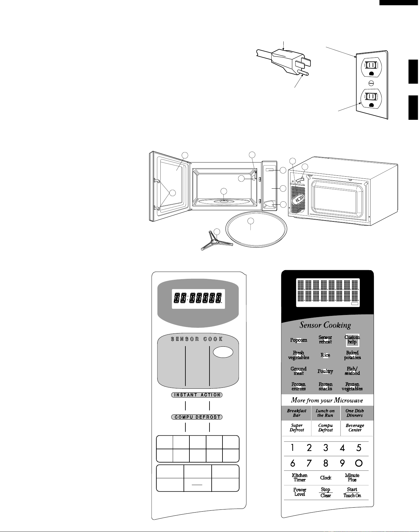
3-Pronged Plug
Grounded
Receptacle Box
Grounding Pin
3-Pronged Receptacle
OVEN DIAGRAM
1. One touch door open button.
Push to open door.
2. Door latches.
The oven will not operate unless the
door is securely closed.
3. Removable turntable support.
4. Removable turntable.
The turntable will rotate clockwise or
counterclockwise.
5. Oven lamp.
It will light when oven is operating or
door is opened.
6. Oven door with see-through window.
7. Ventilation openings. (Rear)
8. Auto-Touch control panel.
9. Time display: Digital display, 99
minutes 99 seconds.
10. Coupling.
11. Wave guide cover.
12. Power supply cord
R-519CK R-530CK/CW
1
6
5
4
2
10
11
12
9
7
8
3
TOUCH CONTROL PANEL
Reheat
Baked
Potatoes
CUSTOM
HELP
Popcorn
Beverage
Frozen
Vegetables
Ground
Meat
Ground
Meat
Kitchen
Timer
Power
Level
Clock
Stop
Clear
Minute
Plus
START
Steaks/
Chops
Chicken
Pieces
Frozen
Entrees
Fresh
Vegetables
Fresh
Rolls/Muffins
Frozen
Rolls/Muffins
Fish/
Seafood
SENSOR COOK
INSTANT ACTION
COMPU DEFROST
12345
6789o
COOK SENSOR LBS KG DEF HELP
Popcorn
Sensor
reheat
Fresh
vegetables
Kitchen
Timer
Minute
Plus
Power
Level
Clock
Stop
Clear
Start
Touch On
Baked
potatoes
Custom
help
Rice
Ground
meat
Frozen
entrees
Frozen
snacks
Frozen
vegetables
Fish/
seafood
Poultry
SENSOR DEFROST COOK
HELP
Downloaded from www.ManualsFile.com manuals search engine

6
R-519CK
R-530CK
R-530CW
OPERATION
DESCRIPTION OF OPERATING SEQUENCE
The following is a description of component functions during
oven operation.
OFF CONDITION
Closing the door activates the door sensing switch and
secondary interlock switch. (In this condition, the monitor
switch contacts are opened.)
When oven is plugged in, 120 volts A.C. is supplied to the
control unit. (Figure O-1).
1. The display will show flashing "88:88" (for R-519CK).
The display will show "SHARP SIMPLY PRESS CLEAR
AND PRESS CLOCK" (for R-530CK/CW).
To set any program or set the clock, you must first touch
the STOP/CLEAR pad. The display will clear, and " : "
will appear.
COOKING CONDITION
Program desired cooking time by touching the NUMBER
pads. Program the power level by touching the POWER
LEVEL pad and then a Number pad.
When the START pad is touched, the following operations
occur:
1. The contacts of relays are closed and components
connected to the relays are turned on as follows.
(For details, refer to Figure O-2)
RELAY CONNECTED COMPONENTS
RY-1 oven lamp/turntable motor/fan motor
RY-2 power transformer
2. 120 volts A.C. is supplied to the primary winding of the
power transformer and is converted to about 3.3 volts
A.C. output on the filament winding, and approximately
2370 volts A.C. on the high voltage winding.
3. The filament winding voltage heats the magnetron
filament and the H.V. winding voltage is sent to a voltage
doubler circuit.
4. The microwave energy produced by the magnetron is
channelled through the waveguide into the cavity feed-
box, and then into the cavity where the food is placed to
be cooked.
5. Upon completion of the cooking time, the power
transformer, oven lamp, etc. are turned off, and the
generation of microwave energy is stopped. The oven
will revert to the OFF condition.
6. When the door is opened during a cook cycle, the
monitor switch, door sensing switch, secondary interlock
switch, relay (RY1) and primary interlock relay are
activated with the following results. The circuits to the
turntable motor, the cooling fan motor, and the high
voltage components are de-energized, the oven lamp
remains on, and the digital read-out displays the time still
remaining in the cook cycle when the door was opened.
7. The monitor switch electrically monitors the operation of
the secondary interlock switch and primary interlock
relay and is mechanically associated with the door so
that it will function in the following sequence.
(1) When the door opens from the closed position, the
primary interlock relay (RY2) and secondary interlock
switch open their contacts. And contacts of the relay
(RY1) remains closed. Then the monitor switch contacts
close.
(2) When the door is closed from the open position, the
monitor switch contacts open first. Then the contacts of
the secondary interlock switch and door sensing switch
close. And contacts of the relay (RY1) open.
If the secondary interlock switch and primary interlock relay
(RY2) fail with the contacts closed when the door is opened,
the closing of the monitor switch contacts will form a short
circuit through the monitor fuse, secondary interlock switch,
relay (RY1) and primary interlock relay (RY2), causing the
monitor fuse to blow.
POWER LEVEL P-0 TO P-90 COOKING
When Variable Cooking Power is programmed, the 120
volts A.C. is supplied to the power transformer intermittently
through the contacts of relay (RY-2) which is operated by the
control unit within a 32 second time base. Microwave power
operation is as follows:
VARI-MODE ON TIME OFF TIME
Power 10(P-HI) 32 sec. 0 sec.
(100% power)
Power 9(P-90) 30 sec. 2 sec.
(approx. 90% power)
Power 8(P-80) 26 sec. 6 sec.
(approx. 80% power)
Power 7(P-70) 24 sec. 8 sec.
(approx. 70% power)
Power 6(P-60) 22 sec. 10 sec.
(approx. 60% power)
Power 5(P-50) 18 sec. 14 sec.
(approx. 50% power)
Power 4(P-40) 16 sec. 16 sec.
(approx. 40% power)
Power 3(P-30) 12 sec. 20 sec.
(approx. 30% power)
Power 2(P-20) 8 sec. 24 sec.
(approx. 20% power)
Power 1(P-10) 6 sec. 26 sec.
(approx. 10% power)
Power 0(P-0) 0 sec. 32 sec.
(0% power)
Note: The ON/OFF time ratio does not correspond with
the percentage of microwave power, because
approx. 2 seconds are needed for heating of the
magnetron filament.
Downloaded from www.ManualsFile.com manuals search engine
7
R-519CK
R-530CK
R-530CW
SENSOR COOKING CONDITION
Using the SENSOR function, the food is cooked without
figuring time, power level or quantity. When the oven senses
enough steam from the food, it relays the information to its
microprocessor which will calculate the remaining cooking
time and power level needed for best results. When the food
is cooked, water vapor is developed. The sensor “senses”
the vapor and its resistance increases gradually. When the
resistance reaches the value set according to the menu,
supplementary cooking is started.
The time of supplementary cooking is determined by experi-
ment with each food category and inputted into the LSI.
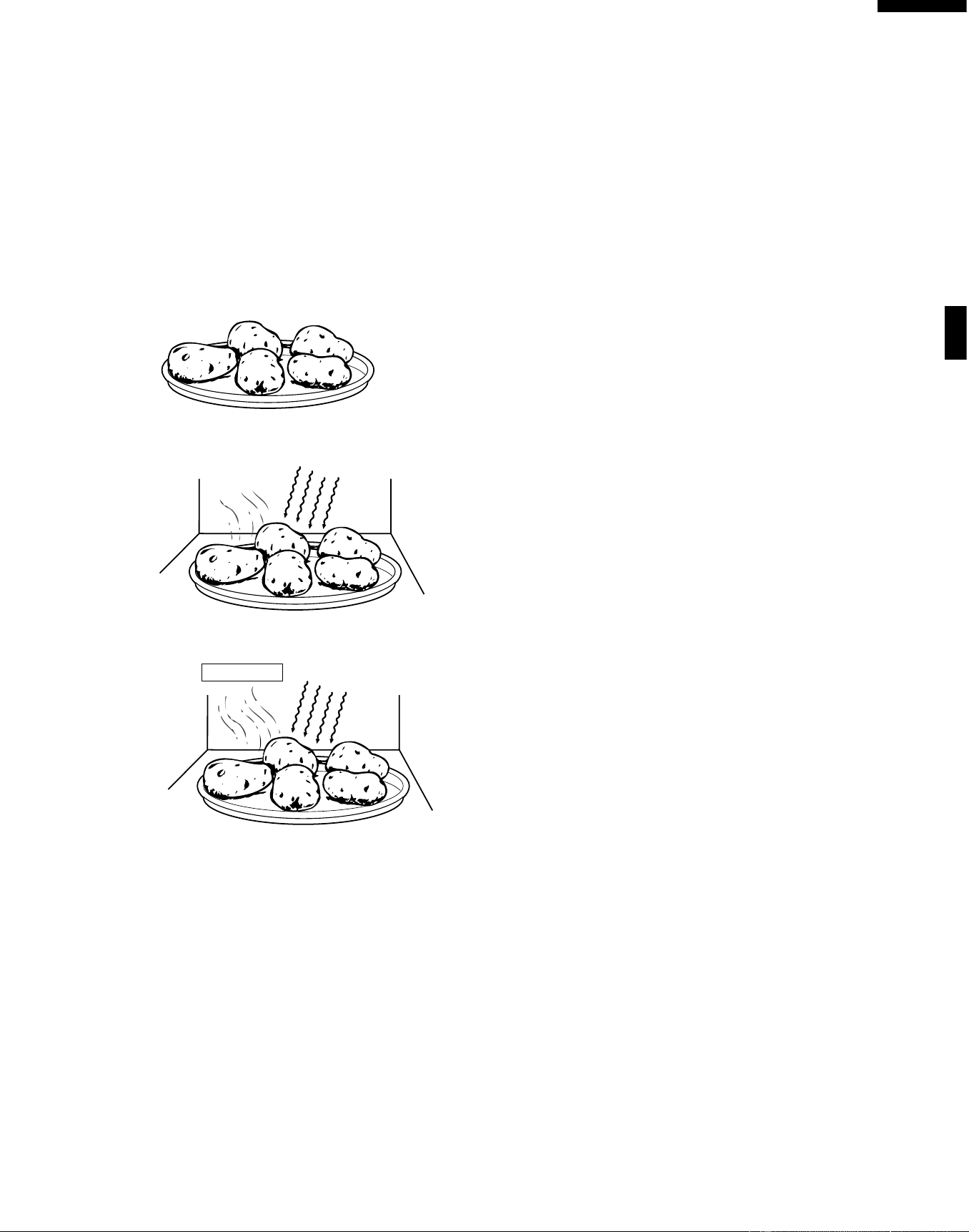
An example of how sensor works: (POTATOES)
1. Potatoes at room temperature. Vapor is emitted very
slowly.
2. Heat Potatoes. Moisture and humidity is emitted rapidly.
You can smell the aroma as it cooks.
3. Sensor detects moisture and humidity and calculates
cooking time and variable power.
Cooking Sequence.
1. Touch one of the SENSOR pads (for R-519CK). Touch
one of the SENSOR pads and then touch the Start pad
(for R-530CK/CW).
NOTE: The oven should not be operated on SENSOR
immediately after plugging in the unit. Wait two
minutes before cooking on SENSOR.
2. The coil of shut-off relay (RY-1) is energized, the turntable
motor, oven lamp and cooling fan motor are turned on,
but the power transformer is not turned on.
3. After about 16 seconds, the cook relay (RY-2) is
energized. The power transformer is turned on,
microwave energy is produced and first stage is started.
The 16 seconds is the cooling time required to remove
any vapor from the oven cavity and sensor.
NOTE: During this first stage, do not open the door or touch
STOP/CLEAR pad.
4. When the sensor detects the vapor emitted from the
food, the display switches over to the remaining cooking
time and the timer counts down to zero.
At this time, the door may be opened to stir, turn, or
season food.
5. When the timer reaches zero, an audible signal sounds.
The shut-off relay and cook relay are de-energized and
the power transformer, oven lamp, etc. are turned off.
6. Opening the door or touching the STOP/CLEAR pad, the
time of day will reappear on the display and the oven will
revert to an OFF condition.
MICROWAVE
MICROWAVE
AH SENSOR
Downloaded from www.ManualsFile.com manuals search engine
8
R-519CK
R-530CK
R-530CW
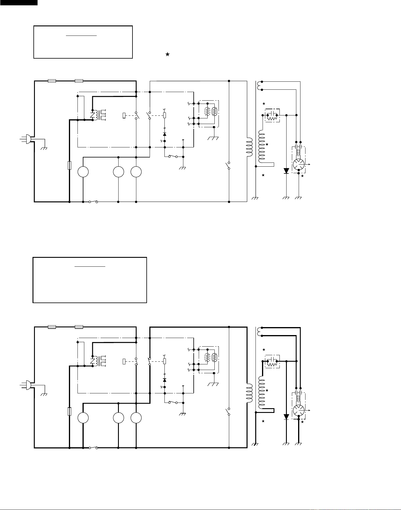
Figure O-1. Oven Schematic-Off Condition
SCHEMATIC
NOTE: CONDITION OF OVEN
1. DOOR CLOSED.
2. CLOCK APPEARS ON DISPLAY.
SCHEMATIC
NOTE: CONDITION OF OVEN
1. DOOR CLOSED.
2. COOKING TIME PROGRAMMED.
3. VARIABLE COOKING CONTROL "HIGH".
4. "START" PAD TOUCHED.
Figure O-2. Oven Schematic-Cooking Condition
NOTE: Indicates components with potential above 250 V.
120V AC
60 Hz
OVEN
LAMP
TURN-
TABLE
MOTOR
FAN
MOTOR
MONITOR
SWITCH
H.V. RECTIFIER
MAGNETRON
SECONDARY
INTERLOCK
SWITCH
TTM
OL FM
MONITOR
FUSE 20A
CAVITY
TEMP.
FUSE
MAGNETRON
TEMP.
FUSE
A1
A2
COM.
COM.
COM.N.O.
N.C.
N.O.
DOOR
SENSING
SWITCH
(RY-1)
(RY-2)
CONTROL UNIT
PRIMARY
INTERLOCK
RELAY
B1 B2
GRN
POWER
TRANSFORMER
CAPACITOR 1.0µF
AC 2300V
F3
F1
F2
AH SENSOR
120V AC
60 Hz
OVEN
LAMP
TURN-
TABLE
MOTOR
FAN
MOTOR
MONITOR
SWITCH
H.V. RECTIFIER
MAGNETRON
SECONDARY
INTERLOCK
SWITCH
TTM
OL FM
CAVITY
TEMP.
FUSE
A1
A2
COM.
COM.
COM.N.O.
N.C.
N.O.
DOOR
SENSING
SWITCH
(RY-1)
(RY-2)
CONTROL UNIT
PRIMARY
INTERLOCK
RELAY
B1 B2
GRN
POWER
TRANSFORMER
CAPACITOR 1.0µF
AC 2300V
MONITOR
FUSE 20A
MAGNETRON
TEMP.
FUSE
F3
F1
F2
Downloaded from www.ManualsFile.com manuals search engine
9
R-519CK
R-530CK
R-530CW
DESCRIPTION AND FUNCTION OF COMPONENTS
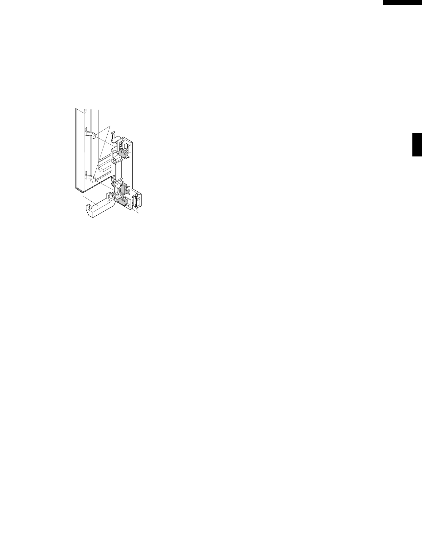
DOOR OPEN MECHANISM
The door is opened by pushing the open button on the
control panel, refer to the Figure D-1. When the open button
is pushed, the open button pushes up the switch lever, and
then the switch lever pushes up the latch head. The latch
heads are moved upward and released from latch hook.
Now the door will open.
Figure D-1. Door Open Mechanism
DOOR SENSING AND SECONDARY INTERLOCK
SWITCHES
The secondary interlock switch is mounted in the lower
position of the latch hook and the door sensing switch in the
primary interlock system is mounted in the upper position of
the latch hook. They are activated by the latch heads on the
door. When the door is opened, the switches interrupt the
power to all high voltage components. A cook cycle cannot
take place until the door is firmly closed thereby activating
both interlock switches. The primary interlock system con-
sists of the door sensing switch and primary interlock relay
located on the control circuit board.
MONITOR SWITCH
The monitor switch is activated (the contacts opened) by the
latch head on the door while the door is closed. The switch
is intended to render the oven inoperative, by means of
blowing the monitor fuse, when the contacts of the primary
interlock relay (RY2) and secondary interlock switch fail to
open when the door is opened.
Functions:
1. When the door is opened, the monitor switch contact close
(to the ON condition) due to their being normally closed. At
this time the primary interlock relay (RY2) and secondary
interlock switch are in the OFF condition (contacts open)
due to their being normally open contact switches.
2. As the door goes to a closed position, the monitor switch
contacts are first opened and then the door sensing switch
and the secondary interlock switch contacts close. (On
opening the door, each of these switches operate inversely.)
3. If the door is opened, and the primary interlock relay
(RY2) and secondary interlock switch contacts fail to
open, the monitor fuse blows simultaneously with closing
of the monitor switch contacts.
CAUTION: BEFORE REPLACING A BLOWN MONITOR
FUSE TEST THE DOOR SENSING SWITCH,
PRIMARY INTERLOCK RELAY (RY2), RELAY
(RY1), SECONDARY INTERLOCK SWITCH
AND MONITOR SWITCH FOR PROPER OP-
ERATION. (REFER TO CHAPTER "TEST PRO-
CEDURE").
NOTE: MONITOR FUSE AND MONITOR SWITCH ARE
REPLACED AS AN ASSEMBLY.
TURNTABLE MOTOR
The turntable motor rotates the turntable located on the
bottom of the oven cavity, so that the foods on the turntable
cook evenly during cooking. The turntable may turn in either
direction.
COOLING FAN MOTOR
The cooling fan motor drives a blade which draws external
cool air. This cool air is directed through the air vanes
surrounding the magnetron and cools the magnetron. This air
is channelled through the oven cavity to remove steam and
vapors given off from the heating foods. It is then exhausted
through the exhausting air vents at the oven cavity.
MONITOR FUSE
1. The monitor fuse blows when the contacts (COM-NO) of
the primary interlock relay (RY2) and secondary interlock
switch remain closed with the oven door open and when
the monitor switch closes.
2. If the wire harness or electrical components are short-
circuited, this monitor fuse blows to prevent an electric
shock or fire hazard.
CAVITY TEMPERATURE FUSE
The cavity temperature fuse located on the top of the oven
cavity, is designed to prevent damage to the oven by fire. If the
food load is overcooked, by either error in cook time or defect
in the control unit, the cavity temperature fuse will open.
Under normal operation, the cavity temperature fuse remains
closed. However, when abnormally high temperatures are
reached within the oven cavity, the cavity temperature fuse will
open at 302˚F(150˚C) causing the oven to shut down.
NOTE: This is a fuse. It does not reset.
MAGNETRON TEMPERATURE FUSE
The magnetron temperature fuse located near the magnetron
is designed to prevent damage to the magnetron if an over
heated condition develops in the tube due to cooling fan
failure, obstructed air guide, dirty or blocked air intake, etc.
Under normal operation, the magnetron temperature fuse
remains closed. However, when abnormally high tempera-
tures are reached within the magnetron, the magnetron
temperature fuse will open at 302˚F(150˚C) causing the oven
to shut down.
NOTE: This is a fuse. It does not reset.
Door Sensing
Switch
Monitor Switch
Switch Lever
Secondary Interlock
Switch
Latch Heads
Door
Downloaded from www.ManualsFile.com manuals search engine

10
R-519CK
R-530CK
R-530CW
TROUBLESHOOTING GUIDE
Never touch any part in the circuit with your hand or an uninsulated tool while the power supply is connected.
When troubleshooting the microwave oven, it is helpful to follow the Sequence of Operation in performing the checks. Many
of the possible causes of trouble will require that a specific test be performed. These tests are given a procedure letter which
will be found in the "Test Procedure "section.
IMPORTANT: If the oven becomes inoperative because of a blown monitor fuse, check the monitor switch, relay (RY1)
primary interlock relay (RY2), door sensing switch and secondary interlock switch before replacing the
monitor fuse. If the monitor fuse is replaced, the monitor switch must also be replaced. Use part FFS-BA016/
KIT as an assembly.
IMPORTANT: Whenever troubleshooting is performed with the power supply cord disconnected. It may in, some cases,
be necessary to connect the power supply cord after the outer case has been removed, in this event,
1. Disconnect the power supply cord, and then remove outer case.
2. Open the door and block it open.
3. Discharge high voltage capacitor.
4. Disconnect the leads to the primary of the power transformer.
5. Ensure that the leads remain isolated from other components and oven chassis by using insulation tape.
6. After that procedure, reconnect the power supply cord.
When the testing is completed
1. Disconnect the power supply cord, and then remove outer case.
2. Open the door and block it open.
3. Discharge high voltage capacitor.
4. Reconnect the leads to the primary of the power transformer.
5. Reinstall the outer case (cabinet).
6. Reconnect the power supply cord after the outer case is installed.
7. Run the oven and check all functions.
Downloaded from www.ManualsFile.com manuals search engine
11
R-519CK
R-530CK
R-530CW
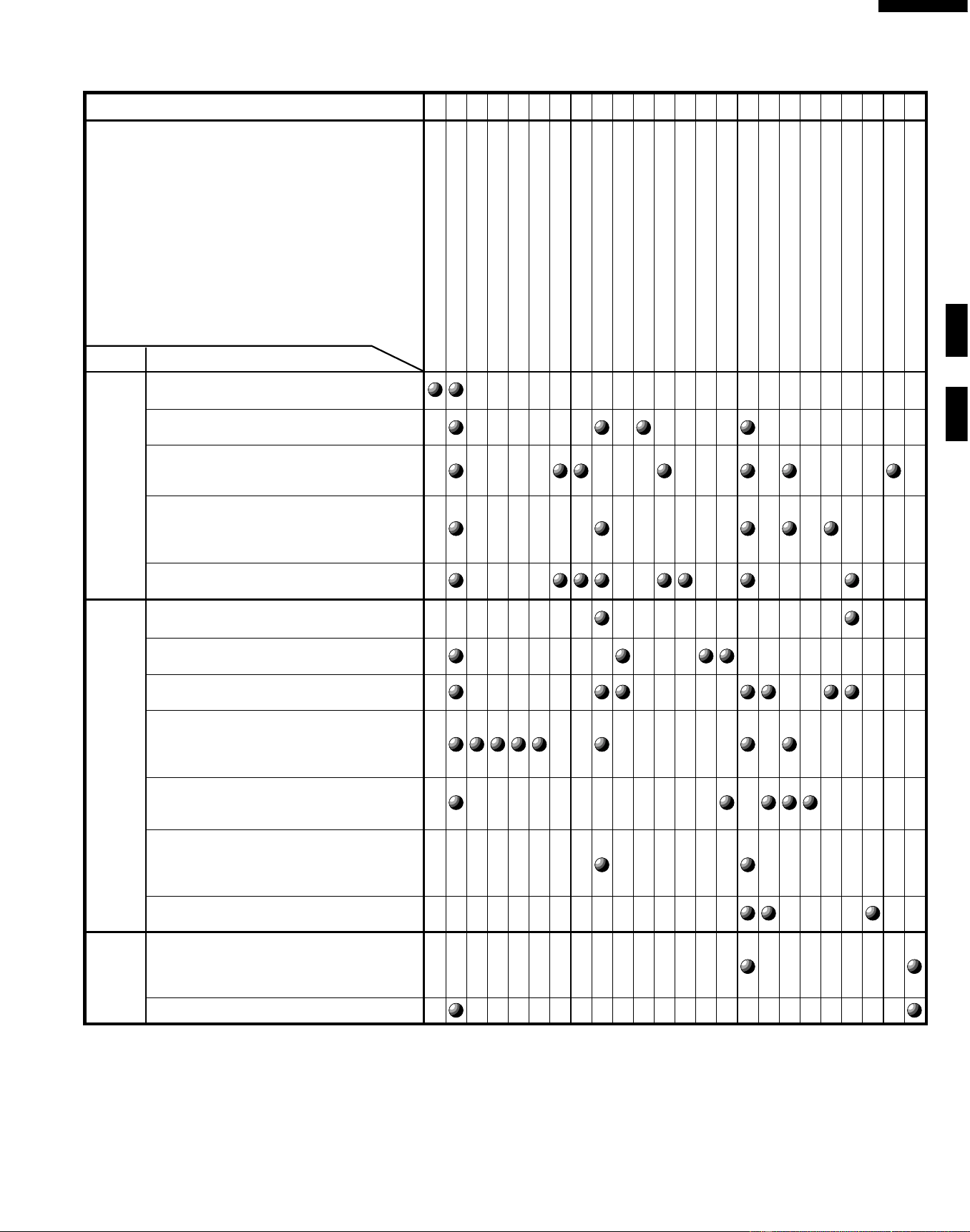
CK = Check / RE = Replace
SHORT IN POWER CORD
SHORT OR OPENED WIRING
MAGNETRON
POWER TRANSFORMER
H.V. RECTIFIER ASSEMBLY
HIGH VOLTAGE CAPACITOR
CAVITY TEMPERATURE FUSE
MAGNETRON TEMPERATURE FUSE
PRIMARY INTERLOCK SYSTEM
SECONDARY INTERLOCK SWITCH
MONITOR SWITCH
MONITOR FUSE
OVEN LAMP OR SOCKET
COOLING FAN MOTOR
TURNTABLE MOTOR
TOUCH CONTROL PANEL
WRONG OPERATION
LOW VOLTAGE
DIRTY OVEN CAVITY
KEY UNIT
RELAY (RY1)
COMPU DEFROST
FOIL PATTERN ON PWB.
AH SENSOR
Home fuse or circuit breaker blows when
power cord is plugged into wall receptacle.
Monitor fuse blows when power cord is
plugged into wall receptacle.
All letters and indicators do not appear in
display when power cord is first plugged
into wall outlet.
Display does not operate properly when
STOP/CLEAR key is touched. (Buzzer
should sound and ":" or time of day
should appear in display.)
Oven lamp does not light when door is
opened.
Oven lamp does not go out when door is
closed.
Oven lamp lights but fan motor and
turntable motor do not operate.
Oven does not go into cook cycle when
START pad is touched
Oven seems to be operating but little or
no heat is produced in oven load. (Food
incompletely cooked or not cooked at all
at end of cook cycle.)
Oven goes into a cook cycle but
extremely uneven heating is produced in
oven load (food).
Oven does not cook properly when
programmed for Cooking Power 5 mode.
(Operates properly on Cooking Power 10
(HIGH) mode.)
Oven goes into COMPU DEFROST but
food is not defrosted well.
AH sensor does not end during Sensor
cooking condition. (Oven does not shut
off after a cup of water is boiling by
sensor cooking.)
Oven stops at 16 sec. after starting.
RE RE ABCDEEFFGHRE RE CK I CK CK CK JKLMN
TEST PROCEDURE
POSSIBLE CAUSE
AND
DEFECTIVE PARTS
COOKING
CONDITION
CONDITION
PROBLEM
OFF
CONDITION
SENSOR
COOKING
CONDITION
Downloaded from www.ManualsFile.com manuals search engine

12
R-519CK
R-530CK
R-530CW
B POWER TRANSFORMER TEST
1. Disconnect the power supply cord, and then remove outer case.
2. Open the door and block it open.
3. Discharge high voltage capacitor.
4. Disconnect the primary input terminals and measure the resistance of the transformer with an
ohmmeter. Check for continuity of the coils with an ohmmeter. On the R x 1 scale, the resistance of
the primary coil should be less than 1 ohm and the resistance of the high voltage coil should be
approximately 90 ohms; the resistance of the filament coil should be less than 1 ohm.
5. Reconnect all leads removed from components during testing.
6. Reinstall the outer case (cabinet).
7. Reconnect the power supply cord after the outer case is installed.
8. Run the oven and check all functions.
TEST PROCEDURES
PROCEDURE
LETTER
COMPONENT TEST
1. Disconnect the power supply cord, and then remove outer case.
2. Open the door and block it open.
3. Discharge high voltage capacitor.
4. To test for an open filament, isolate the magnetron from the high voltage circuit. A continuity check
across the magnetron filament leads should indicate less than 1 ohm.
5. To test for a shorted magnetron, connect the ohmmeter leads between the magnetron filament leads
and chassis ground. This test should indicate an infinite resistance. If there is little or no resistance
the magnetron is grounded and must be replaced.
6. Reconnect all leads removed from components during testing.
7. Reinstall the outer case (cabinet).
8. Reconnect the power supply cord after the outer case is installed.
9. Run the oven and check all functions.
MICROWAVE OUTPUT POWER
The following test procedure should be carried out with the microwave oven in a fully assembled
condition (outer case fitted).
HIGH VOLTAGES ARE PRESENT DURING THE COOK CYCLE, SO EXTREME CAUTION SHOULD
BE OBSERVED.
Power output of the magnetron can be measured by performing a water temperature rise test. This test
should only be used if above tests do not indicate a faulty magnetron and there is no defect in the following
components or wiring: silicon rectifier, high voltage capacitor and power transformer. This test will require
a 16 ounce (453cc) measuring cup and an accurate mercury thermometer or thermocouple type
temperature tester. For accurate results, the following procedure must be followed carefully:
1. Fill the measuring cup with 16 oz. (453cc) of tap water and measure the temperature of the water with
a thermometer or thermocouple temperature tester. Stir the thermometer or thermocouple through
the water until the temperature stabilizes. Record the temperature of the water.
2. Place the cup of water in the oven. Operate oven at POWER 10(HIGH) selecting more than 60
seconds cook time. Allow the water to heat for 60 seconds, measuring with a stop watch, second hand
of a watch or the digital read-out countdown.
3. Remove the cup from the oven and again measure the temperature, making sure to stir the
thermometer or thermocouple through the water until the maximum temperature is recorded.
4. Subtract the cold water temperature from the hot water temperature. The normal result should be 38
to78˚F(21 to 42.6˚C) rise in temperature. If the water temperatures are accurately measured and
tested for the required time period the test results will indicate if the magnetron tube has low power
output (low rise in water temperature) which would extend cooking time or high power output (high
rise in water temperature) which would reduce cooking time. Because cooking time can be adjusted
to compensate for power output, the magnetron tube assembly should be replaced only if the water
temperature rise test indicates a power output well beyond the normal limits. The test is only accurate
if the power supply line voltage is 120 volts and the oven cavity is clean.
A MAGNETRON ASSEMBLY TEST
Downloaded from www.ManualsFile.com manuals search engine

13
R-519CK
R-530CK
R-530CW
TEST PROCEDURES
PROCEDURE
LETTER
COMPONENT TEST
1. Disconnect the power supply cord, and then remove outer case.
2. Open the door and block it open.
3. Discharge high voltage capacitor.
4. If the capacitor is open, no high voltage will be available to the magnetron. Disconnect input leads
and check for short or open between the terminals using an ohmmeter.
Checking with a high ohm scale, if the high voltage capacitor is normal, the meter will indicate
continuity for a short time and should indicate an open circuit once the capacitor is charged. If the
above is not the case, check the capacitor with an ohmmeter to see if it is shorted between either of
the terminals and case. If it is shorted, replace the capacitor.
5. Reconnect all leads removed from components during testing.
6. Reinstall the outer case (cabinet).
7. Reconnect the power supply cord after the outer case is installed.
8. Run the oven and check all functions.
D HIGH VOLTAGE CAPACITOR TEST
E CAVITY TEMPERATURE FUSE TEST
1. Disconnect the power supply cord, and then remove outer case.
2. Open the door and block it open.
3. Discharge high voltage capacitor.
4. A continuity check across the cavity temperature fuse terminals should indicate a closed circuit unless
the temperature of the cavity temperature fuse reaches approximately 302˚F(150˚C). An open cavity
temperature fuse indicates overheating of the oven, exchange the cavity temperature fuse and check
inside of oven cavity and for improper setting of cooking time or operation of control unit. Check for
restricted air flow through the vent holes of the oven cavity, especially the cooling fan and air guide.
5. Reconnect all leads removed from components during testing.
6. Reinstall the outer case (cabinet).
7. Reconnect the power supply cord after the outer case is installed.
8. Run the oven and check all functions.
MAGNETRON TEMPERATURE FUSE TEST
1. Disconnect the power supply cord, and then remove outer case.
2. Open the door and block it open.
3. Discharge high voltage capacitor.
4. A continuity check across the magnetron temperature fuse terminals should indicate a closed circuit
unless the temperature of the magnetron temperature fuse reaches approximately 302˚F(150˚C). An
open magnetron temperature fuse indicates overheating of the magnetron. Check for restricted air
flow to the magnetron, especially the cooling fan air guide.
C HIGH VOLTAGE RECTIFIER TEST
1. Disconnect the power supply cord, and then remove outer case.
2. Open the door and block it open.
3. Discharge high voltage capacitor.
4. Isolate the rectifier from the circuit. Using the highest ohm scale of the meter, read the resistance
across the terminals and observe, reverse the leads to the rectifier terminals and observe meter
reading. If a short is indicated in both directions, or if an infinite resistance is read in both directions,
the rectifier is probably defective and should be replaced.
5. Reconnect all leads removed from components during testing.
6. Reinstall the outer case (cabinet).
7. Reconnect the power supply cord after the outer case is installed.
8. Run the oven and check all functions.
NOTE: Be sure to use an ohmmeter that will supply a forward bias voltage of more than 6.3 volts.
(HIGH VOLTAGES ARE PRESENT AT THE HIGH VOLTAGE TERMINAL, SO DO NOT ATTEMPT TO
MEASURE THE FILAMENT AND HIGH VOLTAGE.)
Downloaded from www.ManualsFile.com manuals search engine

14
R-519CK
R-530CK
R-530CW
TEST PROCEDURES
PROCEDURE
LETTER
COMPONENT TEST
1. Disconnect the power supply cord, and then remove outer case.
2. Open the door and block it open.
3. Discharge high voltage capacitor.
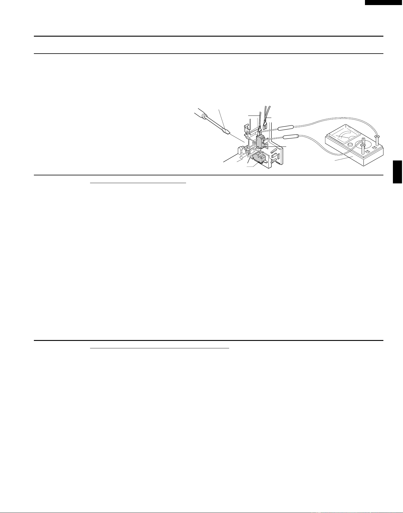
4. Before performing this test, make sure that the secondary interlock switch and the primary interlock
relay are operating properly, according to the above Switch Test Procedure. Disconnect the wire lead
from the monitor switch (COM) terminal. Check the monitor switch operation by using the ohmmeter
as follows. When the door is open, the meter should indicate a closed circuit. When the monitor switch
actuator is pushed by a screw driver through the lower latch hole on the front plate of the oven cavity
5. Reconnect all leads removed from components during testing.
6. Reinstall the outer case (cabinet).
7. Reconnect the power supply cord after the outer case is installed.
8. Run the oven and check all functions.
CAUTION: IF THE TEMPERATURE FUSE INDICATES AN OPEN CIRCUIT AT ROOM TEMPERA-
TURE, REPLACE TEMPERATURE FUSE.
1. Disconnect the power supply cord, and then remove outer case.
2. Open the door and block it open.
3. Discharge high voltage capacitor.
4. Isolate the switch and connect the ohmmeter to the common (COM.) and normally open (NO) terminal
of the switch. The meter should indicate an open circuit with the door open and a closed circuit with
the door closed. If improper operation is indicated, replace the secondary interlock switch.
5. Reconnect all leads removed from components during testing.
6. Reinstall the outer case (cabinet).
7. Reconnect the power supply cord after the outer case is installed.
8. Run the oven and check all functions.
PRIMARY INTERLOCK SYSTEM TEST
DOOR SENSING SWITCH
1. Disconnect the power supply cord, and then remove outer case.
2. Open the door and block it open.
3. Discharge high voltage capacitor.
4. Isolate the switch and connect the ohmmeter to the common (COM.) and normally open (NO) terminal
of the switch. The meter should indicate an open circuit with the door open and a closed circuit with
the door closed. If improper operation is indicated, replace the door sensing switch.
5. Reconnect all leads removed from components during testing.
6. Reinstall the outer case (cabinet).
7. Reconnect the power supply cord after the outer case is installed.
8. Run the oven and check all functions.
NOTE: If the door sensing switch contacts fail in the open position and the door is closed, the cooling
fan, turntable and oven light will be activated by RY1.
PRIMARY INTERLOCK RELAY (RY2)
1. Disconnect the power supply cord, and then remove outer case.
2. Open the door and block it open.
3. Discharge high voltage capacitor.
4. Disconnect two (2) wire leads from the male tab terminals of the Primary Interlock Relay. Check the
state of the relay contacts using a ohmmeter. The relay contacts should be open. If the relay contacts
are closed, replace the circuit board entirely or the relay itself.
5. Reconnect all leads removed from components during testing.
6. Reinstall the outer case (cabinet).
7. Reconnect the power supply cord after the outer case is installed.
8. Run the oven and check all functions.
F SECONDARY INTERLOCK SWITCH TEST
G MONITOR SWITCH TEST
Downloaded from www.ManualsFile.com manuals search engine
15
R-519CK
R-530CK
R-530CW
H BLOWN MONITOR FUSE TEST
TEST PROCEDURES
PROCEDURE
LETTER
COMPONENT TEST
1. Disconnect the power supply cord, and then remove outer case.
2. Open the door and block it open.
3. Discharge high voltage capacitor.
4. If the monitor fuse is blown when the door is opened, check the primary interlock relay, secondary
interlock switch and monitor switch according to the "TEST PROCEDURE" for those switches before
replacing the blown monitor fuse.
CAUTION: BEFORE REPLACING A BLOWN MONITOR FUSE, TEST THE PRIMARY INTERLOCK
RELAY, SECONDARY INTERLOCK SWITCH, DOOR SENSING SWITCH AND MONITOR
SWITCH FOR PROPER OPERATION.
If the monitor fuse is blown by improper switch operation, the monitor fuse and monitor switch must
be replaced with "monitor fuse and monitor switch assembly" part number FFS-BA016/KIT, even if
the monitor switch operates normally. The monitor fuse and monitor switch assembly is comprised
of a 20 ampere fuse and switch.
5. Reconnect all leads removed from components during testing.
6. Reinstall the outer case (cabinet).
7. Reconnect the power supply cord after the outer case is installed.
8. Run the oven and check all functions.
The touch control panel consists of circuits including semiconductors such as LSI, ICs, etc. Therefore,
unlike conventional microwave ovens, proper maintenance cannot be performed with only a voltmeter
and ohmmeter.
In this service manual, the touch control panel assembly is divided into two units, Control Unit and Key
Unit, and also the Control Unit is divided into two units, LSI Unit and Power Unit, and troubleshooting by
unit replacement is described according to the symptoms indicated.
Before testing,
1) Disconnect the power supply cord, and then remove outer case.
2) Open the door and block it open.
3) Discharge high voltage capacitor.
4) Disconnect the leads to the primary of the power transformer.
5) Ensure that these leads remain isolated from other components and oven chassis by using
insulation tape.
6) After that procedure, re-connect the power supply cord.
1. Key Unit.
NOTE ;
1) Disconnect the power supply cord, and then remove outer case.
2) Open the door and block it open.
I TOUCH CONTROL PANEL ASSEMBLY TEST
with the door opened (in this condition the plunger of the monitor switch is pushed in), the meter should
indicate an open circuit. If improper operation is indicated, the switch may be defective. After testing
the monitor switch, reconnect the wire lead to the monitor switch (COM) terminal and check the
continuity of the monitor circuit.
5. Reconnect all leads removed from components during testing.
6. Reinstall the outer case (cabinet).
7. Reconnect the power supply
cord after the outer case is
installed.
8. Run the oven and check all
functions.
Monitor
Switch
Secondary Interlock Switch
Screw Driver
Ohmmeter
RED
WHT/WHT
Downloaded from www.ManualsFile.com manuals search engine

16
R-519CK
R-530CK
R-530CW
3) Discharge high voltage capacitor.
4) Check Key unit ribbon connection before replacement.
5) Reconnect all leads removed from components during testing.
6) Re-install the outer case (cabinet).
7) Reconnect the power supply cord after the outer case is installed.
8) Run the oven and check all functions.
The following symptoms indicate a defective key unit.
a) When touching the pads, a certain pad produces no signal at all.
b) When touching a number pad, two figures or more are displayed.
c) When touching the pads, sometimes a pad produces no signal.
If the Key unit is defective.
1) Disconnect the power supply cord, and then remove outer case.
2) Open the door and block it open.
3) Discharge high voltage capacitor.
4) Replace the Key unit.
5) Reconnect all leads removed from components during testing.
6) Re-install the outer case (cabinet).
7) Reconnect the power supply cord after the outer case is installed.
8) Run the oven and check all functions.
2. Control Unit
The following symptoms indicate a defective control unit. Before replacing the control unit, perform
the Key unit test (Procedure J) to determine if control unit is faulty.
2-1 In connection with pads.
a) When touching the pads, a certain group of pads do not produce a signal.
b) When touching the pads, no pads produce a signal.
2-2 In connection with indicators
a) At a certain digit, all or some segments do not light up.
b) At a certain digit, brightness is low.
c) Only one indicator does not light.
d) The corresponding segments of all digits do not light up; or they continue to light up.
e) Wrong figure appears.
f) A certain group of indicators do not light up.
g) The figure of all digits flicker.
2-3 Other possible problems caused by defective control unit.
a) Buzzer does not sound or continues to sound.
b) Clock does not operate properly.
c) Cooking is not possible.
When testing is completed,
1) Disconnect the power supply cord, and then remove outer case.
2) Open the door and block it open.
3) Discharge high voltage capacitor.
4) Reconnect all leads removed from components during testing.
5) Re-install the outer case (cabinet).
6) Reconnect the power supply cord after the outer case is installed.
7) Run the oven and check all functions.
J KEY UNIT TEST
1. Disconnect the power supply cord, and then remove outer case.
2. Open the door and block it open.
3. Discharge high voltage capacitor.
4. If the display fails to clear when the STOP/CLEAR pad is depressed, first verify the flat ribbon cable
is making good contact, verify that the door sensing switch (stop switch) operates properly; that is the
contacts are closed when the door is closed and open when the door is open. If the door sensing
switch (stop switch) is good, disconnect the flat ribbon cable that connects the key unit to the control
TEST PROCEDURES
PROCEDURE
LETTER
COMPONENT TEST
Downloaded from www.ManualsFile.com manuals search engine
17
R-519CK
R-530CK
R-530CW
TEST PROCEDURES
PROCEDURE
LETTER
COMPONENT TEST
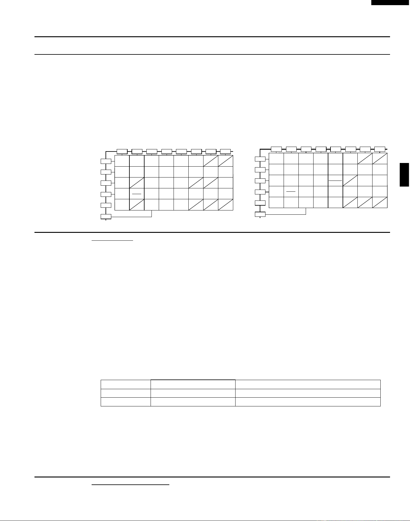
unit and make sure the door sensing switch is closed (either close the door or short the door sensing
switch connecter). Use the Key unit matrix indicated on the control panel schematic and place a
jumper wire between the pins that correspond to the STOP/CLEAR pad making momentary contact.
If the control unit responds by clearing with a beep the key unit is faulty and must be replaced. If the
control unit does not respond, it is a faulty and must be replaced. If a specific pad does not respond,
the above method may be used (after clearing the control unit) to determine if the control unit or key
pad is at fault.
5. Reconnect all leads removed from components during testing.
6. Re-install the outer case (cabinet).
7. Reconnect the power supply cord after the outer case is installed.
8. Run the oven and check all functions.
R-519CK R-530CK/CW
1. Disconnect the power supply cord, and then remove outer case.
2. Open the door and block it open.
3. Discharge high voltage capacitor.
4. Disconnect the leads to the primary of the power transformer.
5. Ensure that these leads remain isolated from other components and oven chassis by using insulation
tape.
6. After that procedure, re-connect the power supply cord.
7. Remove the outer case and check voltage between Pin No. 1 of the 2 pin connector (A) and the
common terminal of the relay RY1 on the control unit with an A.C. voltmeter.
The meter should indicate 120 volts, if not check oven circuit.
RY1 and RY2 Relay Test
These relays are operated by D.C. voltage
Check voltage at the relay coil with a D.C. voltmeter during the microwave cooking operation.
DC. voltage indicated .................... Defective relay.
DC. voltage not indicated .............. Check diode which is connected to the relay coil. If diode is
good, control unit is defective.
RELAY SYMBOL OPERATIONAL VOLTAGE CONNECTED COMPONENTS
RY1 Approx. 24.3V D.C. Oven lamp / Turntable motor / Cooling fan motor
RY2 Approx. 23.4V D.C. Power transformer
8. Disconnect the power supply cord, and then remove outer case.
9. Open the door and block it open.
10.Discharge high voltage capacitor.
11.Reconnect all leads removed from components during testing.
12.Re-install the outer case (cabinet).
13.Reconnect the power supply cord after the outer case is installed.
14.Run the oven and check all functions.
K RELAY TEST
WARNING : The oven should be fully assembled before following procedure.
(1) Place one cup of water in the center of the turntable tray in the oven cavity.
L COMPU DEFROST TEST
5
4
3
21
09876
START
Reheat
Clock
Beverage
Power
Level
Chicken
Pieces
Minute
Plus
Kitchen
Timer
CUSTOM
HELP
Steaks/
Chops
Baked
Potatoes
Fish/
Seafood
Popcorn
Stop
Clear
Frozen
Vegetables
Frozen
Entrees
Fresh
Vegetables
Fresh
Rolls/
Muffins
Frozen
Rolls/
Muffins
Ground Meat
(SENSOR COOK)
Ground Meat
(COMPU DEFROST)
G 8
G 9
G10
G11
G12
G13
G14
G 7 G 6 G 5 G 4 G 3 G 2 G 1
5
4
3
21
09876
Clock
Power
Level
Ground
meat
Frozen
snacks
Minute
Plus
One Dish
Dinners
Lunch on
the Run
Breakfast
Bar
Beverage
Center
Compu
Defrost
Fish/
seafood
Super
Defrost
Sensor
reheat
Kitchen
Timer
Baked
Potatoes
Popcorn
Rice
Poultry
Stop
Clear
Start
Touch On
Frozen
vegetables
Fresh
vegetables
Frozen
entrees
Custom
Help
G 8
G 9
G10
G11
G12
G13
G14
G 7 G 6 G 5 G 4 G 3 G 2 G 1
Downloaded from www.ManualsFile.com manuals search engine
18
R-519CK
R-530CK
R-530CW
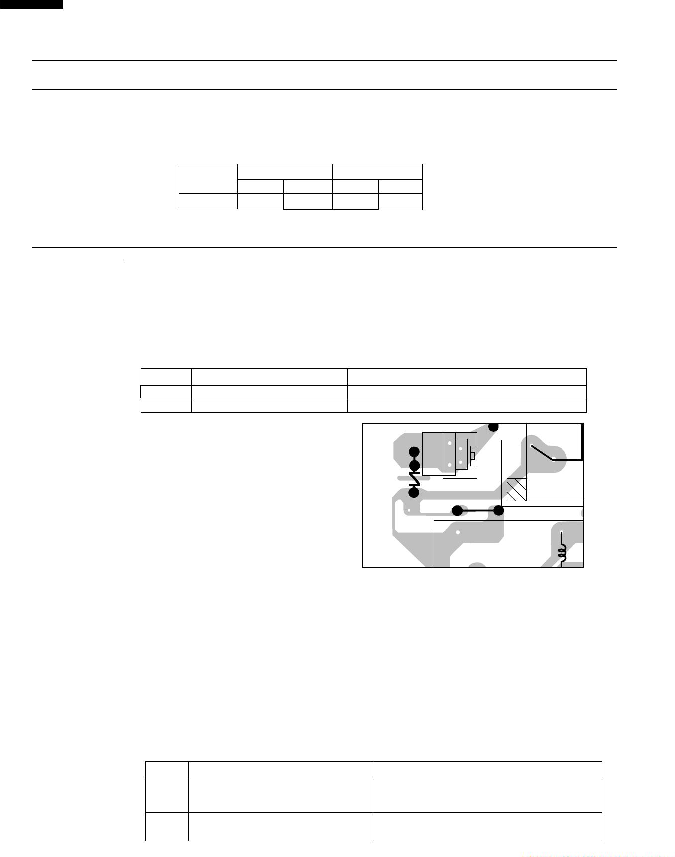
To protect the electronic circuits, this model is provided with a fine foil pattern added to the primary on
the PWB, this foil pattern acts as a fuse.
1. Foil pattern check and repairs.
1) Disconnect the power supply cord, and then remove outer case.
2) Open the door and block it open.
3) Discharge high voltage capacitor.
4) Follow the troubleshooting guide given below for repair.
STEPS OCCURRENCE CAUSE OR CORRECTION
1 Only pattern at "a" is broken. *Insert jumper wire J1 and solder.
2 Pattern at "a" and "b" are broken. *Insert the coil RCILF2003YAZZ between "c" and "d".
5) Make a visual inspection of the varistor.
Check for burned damage and examine
the transformer with a tester for the
presence of layer short-circuit (check
the primary coil resistance which is
approximately 210Ω ± 15%). If any
abnormal condition is detected, replace
the defective parts.
6) Reconnect all leads removed from components during testing.
7) Re-install the outer case (cabinet).
8) Reconnect the power supply cord after the outer case is installed.
9) Run the oven and check all functions.
2. Follow the troubleshooting guide given below, if indicator does not light up after above check and
repairs are finished.
1) Disconnect the power supply cord, and then remove outer case.
2) Open the door and block it open.
3) Discharge high voltage capacitor.
4) Disconnect the leads to the primary of the power transformer.
5) Ensure that these leads remain isolated from other components and oven chassis by using
insulation tape.
6) After that procedure, re-connect the power supply cord.
7) Follow the troubleshooting guide given below for repair.
STEPS OCCURRENCE CAUSE OR CORRECTION
The rated AC voltage is not present between
1 Pin No. 1 of the 2-pin connector (A) and the Check supply voltage and oven power cord.
common terminal of the relay RY1.
2 The rated AC voltage is present at primary Low voltage transformer or secondary circuit defective.
side of low voltage transformer. Check and repair.
M FOIL PATTERN ON THE PRINTED WIRING BOARD TEST
(2) For R-519CK, close the door, touch the " Steaks / chops " pad once.
For R-530CK/CW, close the door, touch the Compu Defrost pad three times and touch the number
pad 5. And then touch the Start pad.
(3) The oven is in Compu Defrost cooking condition.
(4) The oven will operate as follows
WEIGHT 1ST STAGE 2ND STAGE
LEVEL TIME LEVEL TIME
0.5lb 60% 47sec. 40% 37sec.
(5) If improper operation is indicated, the control unit is probably defective and should be checked.
TEST PROCEDURES
PROCEDURE
LETTER
COMPONENT TEST
T1
AC
VRS1
QKITPB026MRE0
OMIF
DU
CN - A
(J1)
a
b
c
d
12
XA
VH
Downloaded from www.ManualsFile.com manuals search engine

19
R-519CK
R-530CK
R-530CW
TEST PROCEDURES
PROCEDURE
LETTER
COMPONENT TEST
8) Disconnect the power supply cord, and then remove outer case.
9) Open the door and block it open.
10) Discharge high voltage capacitor.
11) Reconnect all leads removed from components during testing.
12) Re-install the outer case (cabinet).
13) Reconnect the power supply cord after the outer case is installed.
14) Run the oven and check all functions.
N AH SENSOR TEST
Checking the initial sensor cooking condition
WARNING : The oven should be fully assembled before following procedure.
(1) The oven should be plugged in at least two minutes before sensor cooking.
(2) Room temperature should not exceed 95˚F (35˚C).
(3) The unit should not be installed in any area where heat and steam are generated. The unit should
not be installed, for example, next to a conventional surface unit. Refer to the “INSTALLATION
INSTRUCTIONS” of the operation manual.
(4) Exhaust vents are provided on the back of the unit for proper cooling and air flow in the cavity. To
permit adequate ventilation, be sure to install so as not to block these vents. There should be some
space for air circulation.
(5) Be sure the exterior of the cooking container and the interior of the oven are dry. Wipe off any moisture
with a dry cloth or paper towel.
(6) The Sensor works with food at normal storage temperature. For example, chicken pieces would be
at refrigerator temperature and canned soup at room temperature.
(7) Avoid using aerosol sprays or cleaning solvents near the oven while using Sensor settings. The
sensor will detect the vapor given of by the spray and turn off before food is properly cooked.
(8) If the sensor has not detected the vapor of the food, ERROR will appear and the oven will shut off.
Water load cooking test
WARNING : The oven should be fully assembled before following procedure.
Make sure the oven has been plugged in at least two minutes before checking sensor cook operation.
The cabinet should be installed and screws tightened.
(1) Fill approximately 200 milliliters (7.2 oz) of tap water in a 1000 milliliter measuring cup.
(2) Place the container on the center of tray in the oven cavity.
(3) Close the door.
(4) For R-519CK, touch REHEAT pad once. Now, the oven is in the sensor cooking condition and
“REHEAT” "SENSOR" will appear in the display.
For R-530CK/CW, touch Sensor reheat pad once and touch the start pad. Now, the oven is in the
sensor cooking condition and "SENSOR REHEAT" will appear in the display.
(5) The oven will operate for the first 16 seconds, without generating microwave energy.
NOTE: ERROR will appear if the door is opened or STOP/CLEAR pad is touched during first stage of
sensor cooking.
(6) After approximately 16 seconds, microwave energy is produced, and the display should start to count
down the remaining cooking time and oven should turn off after water is boiling (bubbling).
If the oven does not turn off, replace the AH sensor or check the control unit, refer to explanation below.
TESTING METHOD FOR AH SENSOR AND/OR CONTROL UNIT
To determine if the sensor is defective, the simplest method is to replace it with a new replacement
sensor.
(1) Disconnect the power supply cord, and then remove outer case.
(2) Open the door and block it open.
(3) Discharge high voltage capacitor.
(4) Remove the AH sensor.
(5) Install the new AH sensor.
(6) Reconnect all leads removed from components during testing.
(7) Re-install the outer case (cabinet).
Downloaded from www.ManualsFile.com manuals search engine
20
R-519CK
R-530CK
R-530CW
TEST PROCEDURES
PROCEDURE
LETTER
COMPONENT TEST
(8) Reconnect the power supply cord after the outer case is installed.
(9) Reconnect the oven to the power supply and check the sensor cook operation as follows:
9-1. Fill approximately 200 milliliters (7.2 oz) of tap water in a 1000 milliliter measuring cup.
9-2. Place the container on the center of tray in the oven cavity.
9-3. Close the door.
9-4. For R-519CK, touch REHEAT pad once.
For R-530CK/CW, touch Sensor reheat pad and touch the Start pad.
9-5. The control panel is in automatic Sensor operation.
9-6. The display will start to count down the remaining cooking time, and the oven will turn off
automatically after the water is boiling (bubbling).
If new sensor dose not operate properly, the problem is with the control unit, and refer to explanation
below.
CHECKING CONTROL UNIT
(1) Disconnect the power supply cord, and then remove outer case.
(2) Open the door and block it open.
(3) Discharge high voltage capacitor.
(4) Disconnect the sensor connector that is mounted to control panel.
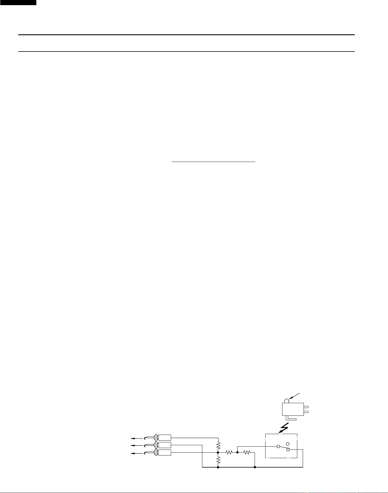
(5) Then connect the dummy resistor circuit (see fig.) to the sensor connector of control panel.
(6) Disconnect the leads to the primary of the power transformer.
(7) Ensure that these leads remain isolated from other components and oven chassis by using
insulation tape.
(8) After that procedure, re-connect the power supply cord.
(9) Check the sensor cook operation proceed as follows:
9-1. For R-519CK, touch REHEAT pad once.
For R-530CK/CW, touch Sensor reheat pad and touch the Start pad.
9-2. The control panel is in the sensor cooking operation.
9-3. After approximately 30 seconds, push plunger of select switch for more than 3 seconds. This
condition is same as judgement by AH sensor.
9-4. After approximately 3 seconds, the display shows “ X X . X X “ which is the remaining cooking
time, and the display count down.
If the above is not the case, the control unit is probably defective.
If the above is proper, the AH sensor is probably defective.
(10) Disconnect the power supply cord, and then remove outer case.
(11) Open the door and block it open.
(12) Discharge high voltage capacitor.
(13) Disconnect the dummy resistor circuit from the sensor connector of control panel.
(14) Carry out necessary repair.
(15) Reconnect all leads removed from components during testing and repairing.
(16) Re-install the outer case (cabinet).
(17) Reconnect the power supply cord after the outer case is installed. Run the oven and check all
functions.
(18) Carry out "Water load cooking test" again and ensure that the oven works properly.
R1,R2 : 22Ω ± 1% 1/2W
R3 : 4.3kΩ ± 5% 1/4W
R4 : 1MΩ ± 5% 1/4W
Sensor Dummy Resistor Circuit
Plunger
NC
NO
COM
COM
NO
NC
R3 R4
R1
R2
1
2
3
F-1
F-2
F-3
To connector (F)
on Control Unit.
CONNECTOR
Downloaded from www.ManualsFile.com manuals search engine

21
R-519CK
R-530CK
R-530CW
TOUCH CONTROL PANEL ASSEMBLY
OUTLINE OF TOUCH CONTROL PANEL
4) Relay Circuit
A circuit to drive the magnetron, fan motor, turntable
motor and light the oven lamp.
5) Buzzer Circuit
The buzzer is responsive to signals from the LSI to
emit audible sounds (key touch sound and
completion sound).
6) Synchronizing Signal Circuit
The power source synchronizing signal is available in
order to compose a basic standard time in the clock
circuit.
It accompanies a very small error because it works
on commercial frequency.
7) Door Sensing Switch
A switch to “tell” the LSI if the door is open or closed.
8) Back Light Circuit
For R-519CK
A circuit to drive the back light (Light emitting diodes
LD1- LD4).
For R-530CK/CW
A circuit to drive the back light (Light emitting diodes
LD10-LD19).
9) Absolute Humidity Sensor Circuit
This circuit detects moisture of the cooking food to
allow its automatic cooking.
The touch control section consists of the following units.
(1) Key Unit
(2) Control Unit (The Control Unit consists of Power Unit
and LSI Unit).
The principal functions of these units and the signals
communicated among them are explained below.
Key Unit
The key unit is composed of a matrix, signals generated
in the LSI are sent to the key unit through P10-P17.
When a key pad is touched, a signal is completed
through the key unit and passed back to the LSI through
AN11, AN10, AN9, P42, P41 and AN8 to perform the
function that was requested.
Control Unit
Control unit consists of LSI, ACL circuit, indicator circuit,
power source circuit, relay circuit, buzzer circuit,
synchronizing signal circuit, absolute humidity sensor
circuit and back light circuit.
1) ACL
This circuit generates a signal which resets the LSI to
the initial state when power is supplied.
2) Indicator Circuit
For R-519CK
This circuit consists of 36 segments and 3 common
electrodes using a Liquid Crystal Display.
For R-530CK/CW
This circuit consists of 40 segments and 16 common
electrodes using a Liquid Crystal Display.
The Liquid Crystal Display (LCD) is drived by LCD
driver IC3.
3) Power Source Circuit
This circuit generates voltages necessary in the
control unit from the AC line voltage.
In addition, the synchronizing signal is available in
order to compose a basic standard time in the clock
circuit.
Symbol Voltage Application
VC -5V LSI(IC1)
Downloaded from www.ManualsFile.com manuals search engine
22
R-519CK
R-530CK
R-530CW
LSI(IZA966DR) : R-519CK
The I/O signal of the LSI(IZA966DR) is detailed in the following table.
Pin No. Signal I/O Description
A
B
0.1 sec.
2.0 sec.
H : GND
L : -5V
H : GND
L : -5V
1 AN10 IN Signal coming from touch key.
When either G10 line on key matrix is touched, a corresponding signal out of P10 - P17
will be input into AN10. When no key is touched, the signal is held at "H" level.
2 AN11 IN Signal similar to AN10.
When either G9 line on key matrix is touched, a corresponding signal will be input into AN11.
3 AVSS IN Connected to VC.
4 P10 OUT Key strobe signal.
Signal applied to touch-key section. A pulse signal is input to AN9, AN10, AN11, P41 and
P42 terminal while one of G8 line keys on key matrix is touched.
5 P11 OUT Key strobe signal.
Signal applied to touch-key section. A pulse signal is input to AN9, AN10, AN11, P41 and
P42 terminal while one of G7 line keys on key matrix is touched.
6 P12 OUT Key strobe signal.
Signal applied to touch-key section. A pulse signal is input to AN9, AN10, AN11, P41 and
P42 terminal while one of G6 line keys on key matrix is touched.
7 P13 OUT Key strobe signal.
Signal applied to touch-key section. A pulse signal is input to AN9, AN10, AN11, P41 and
P42 terminal while one of G5 line keys on key matrix is touched.
8 P14 OUT Key strobe signal.
Signal applied to touch-key section. A pulse signal is input to AN9, AN10, AN11, P41 and
P42 terminal while one of G4 line keys on key matrix is touched.
9 P15 OUT Key strobe signal.
Signal applied to touch-key section. A pulse signal is input to AN9, AN10, AN11, P41 and
P42 terminal while one of G3 line keys on key matrix is touched.
10 P16 OUT Key strobe signal.
Signal applied to touch-key section. A pulse signal is input to AN9, AN10, AN11, P41 and
P42 terminal while one of G2 line keys on key matrix is touched.
11 P17 OUT Key strobe signal.
Signal applied to touch-key section. A pulse signal is input to AN8, AN9, AN10, AN11,
P41 and P42 terminal while one of G1 line keys on key matrix is touched.
12 X1 IN Connected to GND.
13 X2 OUT Terminal not used.
14 VSS IN Power source voltage: -5.0V.
VC voltage of power source circuit input.
15 OSC2 OUT Internal clock oscillation frequency control output.
Output to control oscillation input of OSC2.
16 OSC1 IN Internal clock oscillation frequency input setting.
The internal clock frequency is set by inserting the ceramic filter oscillation circuit with
respect to OSC1 terminal.
17 TEST IN Connected to VC.
18 RES IN Auto clear terminal.
Signal is input to reset the LSI to the initial state when power is applied. Temporarily set "L"
level the moment power is applied, at this time the LSI is reset. Thereafter set at "H" level.
19 P20 OUT Signal to sound buzzer (2.0 kHz).
A: key touch sound.
B: Completion sound.
20-22 P21-P23 OUT Terminal not used.
Downloaded from www.ManualsFile.com manuals search engine
23
R-519CK
R-530CK
R-530CW
Pin No. Signal I/O Description
16.7 msec.
During cooking
H : GND
L : -5V
P-HI
H : GND
L : -5V
H : GND
L : -5V
P-70
ON
ON
OFF
OFF OFF
24 sec.
8 sec.
23 P24 OUT Oven lamp, fan motor and turntable motor driving signal
To turn on and off shut off relay (RY1). The
square waveform voltage is delivered to the
RY1 driving circuit and RY2 control circuit.
24 P25 OUT Magnetron high-voltage circuit driving signal.
To turn on and off the cook relay (RY2). The
signals holds "L" level during microwave cook-
ing and "H" level while not cooking. In other
cooking modes (variable cooking) the signal
turns to "H" level and "L" level in repetition
according to the power level.
(ON and OFF times for other power level.)
25-26 P26-P27 OUT Terminal not used.
27-29 P30-P32 OUT Terminal not used.
30-34 P33-P37 OUT Used for initial balancing of the bridge circuit (absolute humidity sensor).
35 CVCC IN Connected to GND.
36 VSS IN Power source voltage: -5.0V.
The power source voltage to the LSI is input to VSS terminal. Connected to VC.
37-38 V3-V2 IN Power source voltage input terminal.
Standard voltage for LCD.
39-40 V1-V0 IN Power source voltage input terminal.
Standard voltage for LCD. Connected to GND.
41 VCC IN Power source voltage: GND (0V).
The power source voltage to drive the LSI is input to VCC terminal.
42 COM4 OUT Terminal not used.
43 COM3 OUT Common data signal: COM2.
Connected to LCD signal COM2.
44 COM2 OUT Common data signal: COM1.
Connected to LCD signal COM1.
45 COM1 OUT Common data signal: COM0.
Connected to LCD signal COM0.
46-54
SEG1-SEG9
OUT Segment data signal.
Connected to LCD.
The relation between signals are as follows:
LSI signal (Pin No.) LCD (Pin No.) LSI signal (Pin No.) LCD (Pin No.)
SEG 1 (46) ....................................SEG 0 SEG 20 (65) ................................. SEG 18
SEG 2 (47) ....................................SEG 1 SEG 21 (66) ................................. SEG 19
SEG 3 (48) ....................................SEG 2 SEG 22 (67) ................................. SEG 20
SEG 4 (49) ....................................SEG 3 SEG 23 (68) ................................. SEG 21
SEG 5 (50) ....................................SEG 4 SEG 24 (69) ................................. SEG 22
SEG 6 (51) ....................................SEG 5 SEG 25 (70) ................................. SEG 23
SEG 7 (52) ....................................SEG 6 SEG 26 (71) ................................. SEG 24
SEG 8 (53) ....................................SEG 7 SEG 27 (72) ................................. SEG 25
SEG 9 (54) ....................................SEG 8 SEG 28 (73) ................................. SEG 26
SEG 11 (56) ....................................SEG 9 SEG 29 (74) ................................. SEG 27
SEG 12 (57) ...................................SEG 10 SEG 30 (75) ................................. SEG 28
SEG 13 (58) ...................................SEG 11 SEG 31 (76) ................................. SEG 29
SEG 14 (59) ...................................SEG 12 SEG 32 (77) ................................. SEG 30
SEG 15 (60) ...................................SEG 13 SEG 33 (78) ................................. SEG 31
SEG 16 (61) ...................................SEG 14 SEG 34 (79) ................................. SEG 32
SEG 17 (62) ...................................SEG 15 SEG 35 (80) ................................. SEG 33
SEG 18 (63) ...................................SEG 16 SEG 36 (81) ................................. SEG 34
SEG 19 (64) ...................................SEG 17 SEG 37 (82) ................................. SEG 35
55 SEG10 OUT Terminal not used.
Downloaded from www.ManualsFile.com manuals search engine
24
R-519CK
R-530CK
R-530CW
56-82
SEG11-SEG37
OUT Segment data signal.
Signal similar to SEG1.
83-85
SEG38-SEG40
OUT Terminal not used.
86 P40 OUT Terminal not used.
87 P41 IN Signal similar to AN10.
When either G13 line on key matrix is touched, a corresponding signal will be input into P41.
88 P42 IN Signal similar to AN10.
When either G12 line on key matrix is touched, a corresponding signal will be input into P42.
89 IRQ0 IN Signal synchronized with commercial power source frequency.
This is the basic timing for time processing of LSI.
90 AVCC IN A/D converter power source voltage.
The power source voltage to drive the A/D converter in the LSI. Connected to GND.
91 AN0 IN Used for initial balancing of the bridge circuit (absolute humidity sensor). This input is an
analog input terminal from the AH sensor circuit, and connected to the A/D converter built
into the LSI.
92 AN1 IN AH sensor input.
This input is an analog input terminal from the AH sensor circuit, and connected to the
A/D converter built into the LSI.
93 AN2 IN To input signal which communicates the door open/close information to LSI.
Door close "H" level signal (0V). Door open "L" level signal (-5V).
94 AN3 IN Terminal not used.
95 AN4 OUT Terminal not used.
96-98 AN5-AN7 IN Terminal to change cooking input according to the Model.
By using the A/D converter contained in the LSI, DC voltage in accordance with the Model
in operation is applied to set up its cooking constant.
99 AN8 IN Input terminal to judge the model.
The signal will be input into AN8 through one of G1 - G8 lines on key matrix. The LSI will
judge the model by this signal.
100 AN9 IN Signal similar to AN10.
When either G11 line on key matrix is touched, a corresponding signal will be input into AN9.
Pin No. Signal I/O Description
16.7 msec.
H : GND
L : -5V
LSI(IZA950DR) : R-530CK/CW
The I/O signal of the LSI(IZA950DR) is detailed in the following table.
Pin No. Signal I/O Description
1 AN10 IN Signal coming from touch key.
When either G10 line on key matrix is touched, a corresponding signal out of P10 - P17
will be input into AN10. When no key is touched, the signal is held at "H" level.
2 AN11 IN Signal similar to AN10.
When either G9 line on key matrix is touched, a corresponding signal will be input into AN11.
3 AVSS IN Connected to VC.
4 P10 OUT Key strobe signal.
Signal applied to touch-key section. A pulse signal is input to AN9, AN10, AN11, P41 and
P42 terminal while one of G8 line keys on key matrix is touched.
5 P11 OUT Key strobe signal.
Signal applied to touch-key section. A pulse signal is input to AN9, AN10, AN11, P41 and
P42 terminal while one of G7 line keys on key matrix is touched.
6 P12 OUT Key strobe signal.
Signal applied to touch-key section. A pulse signal is input to AN9, AN10, AN11, P41 and
P42 terminal while one of G6 line keys on key matrix is touched.
Downloaded from www.ManualsFile.com manuals search engine
25
R-519CK
R-530CK
R-530CW
Pin No. Signal I/O Description
A
B
0.1 sec.
2.0 sec.
H : GND
L : -5V
H : GND
L : -5V
7 P13 OUT Key strobe signal.
Signal applied to touch-key section. A pulse signal is input to AN9, AN10, AN11, P41 and
P42 terminal while one of G5 line keys on key matrix is touched.
8 P14 OUT Key strobe signal.
Signal applied to touch-key section. A pulse signal is input to AN9, AN10, AN11, P41 and
P42 terminal while one of G4 line keys on key matrix is touched.
9 P15 OUT Key strobe signal.
Signal applied to touch-key section. A pulse signal is input to AN9, AN10, AN11, P41 and
P42 terminal while one of G3 line keys on key matrix is touched.
10 P16 OUT Key strobe signal.
Signal applied to touch-key section. A pulse signal is input to AN9, AN10, AN11, P41 and
P42 terminal while one of G2 line keys on key matrix is touched.
11 P17 OUT Key strobe signal.
Signal applied to touch-key section. A pulse signal is input to AN8, AN9, AN10, AN11,
P41 and P42 terminal while one of G1 line keys on key matrix is touched.
12 X1 IN Connected to GND.
13 X2 OUT Terminal not used.
14 VSS IN Power source voltage: -5.0V.
VC voltage of power source circuit input.
15 OSC2 OUT Internal clock oscillation frequency control output.
Output to control oscillation input of OSC2.
16 OSC1 IN Internal clock oscillation frequency input setting.
The internal clock frequency is set by inserting the ceramic filter oscillation circuit with
respect to OSC1 terminal.
17 TEST IN Connected to VC.
18 RES IN Auto clear terminal.
Signal is input to reset the LSI to the initial state when power is applied. Temporarily set "L"
level the moment power is applied, at this time the LSI is reset. Thereafter set at "H" level.
19 P20 OUT Signal to sound buzzer (2.0 kHz).
A: key touch sound.
B: Completion sound.
20-22 P21-P23 OUT Terminal not used.
23 P24 OUT Oven lamp, fan motor and turntable motor driving signal
To turn on and off shut off relay (RY1). The
square waveform voltage is delivered to the
RY1 driving circuit and RY2 control circuit.
24 P25 OUT Magnetron high-voltage circuit driving signal.
To turn on and off the cook relay (RY2). The
signals holds "L" level during microwave cook-
ing and "H" level while not cooking. In other
cooking modes (variable cooking) the signal
turns to "H" level and "L" level in repetition
according to the power level.
(ON and OFF times for other power level.)
25-26 P26-P27 OUT Terminal not used.
27-29 P30-P32 OUT Terminal not used.
30-34 P33-P37 OUT Used for initial balancing of the bridge circuit (absolute humidity sensor).
35 CVCC IN Connected to GND.
16.7 msec.
During cooking
H : GND
L : -5V
P-HI
H : GND
L : -5V
H : GND
L : -5V
P-70
ON
ON
OFF
OFF OFF
24 sec.
8 sec.
Downloaded from www.ManualsFile.com manuals search engine
26
R-519CK
R-530CK
R-530CW
Pin No. Signal I/O Description
36 VSS IN Power source voltage: -5.0V.
The power source voltage to the LSI is input to VSS terminal. Connected to VC.
37-38 V3-V2 IN Terminal not used.
39-40 V1-V0 IN Power source voltage input terminal.
Standard voltage for LCD. Connected to GND.
41 VCC IN Power source voltage: GND (0V).
The power source voltage to drive the LSI is input to VCC terminal.
42-45 COM4-COM1 OUT Terminal not used.
46-65
SEG1-SEG20
OUT Terminal not used.
66-79 P74-P91 OUT Data output terminal to LCD driver IC3.
80-85
SEG35-SEG40
OUT Terminal not used.
86 P40 OUT Terminal not used.
87 P41 IN Signal similar to AN10.
When either G13 line on key matrix is touched, a corresponding signal will be input into P41.
88 P42 IN Signal similar to AN10.
When either G12 line on key matrix is touched, a corresponding signal will be input into P42.
89 IRQ0 IN Signal synchronized with commercial power source frequency.
This is the basic timing for time processing of LSI.
90 AVCC IN A/D converter power source voltage.
The power source voltage to drive the A/D converter in the LSI. Connected to GND.
91 AN0 IN Used for initial balancing of the bridge circuit (absolute humidity sensor). This input is an
analog input terminal from the AH sensor circuit, and connected to the A/D converter built
into the LSI.
92 AN1 IN AH sensor input.
This input is an analog input terminal from the AH sensor circuit, and connected to the
A/D converter built into the LSI.
93 AN2 IN To input signal which communicates the door open/close information to LSI.
Door close "H" level signal (0V). Door open "L" level signal (-5V).
94 AN3 IN Terminal not used.
95-98 AN4-AN7 IN Terminal to change cooking input according to the Model.
By using the A/D converter contained in the LSI, DC voltage in accordance with the Model
in operation is applied to set up its cooking constant.
99 AN8 IN Input terminal to judge the model.
The signal will be input into AN8 through one of G1 - G8 lines on key matrix. The LSI will
judge the model by this signal.
100 AN9 IN Signal similar to AN10.
When either G11 line on key matrix is touched, a corresponding signal will be input into AN9.
16.7 msec.
H : GND
L : -5V
Downloaded from www.ManualsFile.com manuals search engine
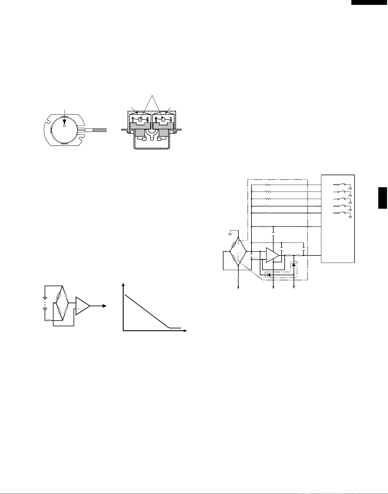
27
R-519CK
R-530CK
R-530CW
ABSOLUTE HUMIDITY SENSOR CIRCUIT
(1) Structure of Absolute Humidity Sensor
The absolute humidity sensor includes two thermistors
as shown in the illustration. One thermistor is housed in
the closed vessel filled with dry air while another in the
open vessel. Each sensor is provided with the protective
cover made of metal mesh to be protected from the
external airflow.
(2) Operational Principle of Absolute Humidity Sensor
The figure below shows the basic structure of an absolute
humidity sensor. A bridge circuit is formed by two
thermistors and two resistors (R1 and R2).
The output of the bridge circuit is to be amplified by the
operational amplifier.
Each thermistor is supplied with a current to keep it
heated at about 150˚C (302˚F), the resultant heat is
dissipated in the air and if the two thermistors are placed
in different humidity conditions they show different
degrees of heat conductivity leading to a potential
difference between them causing an output voltage from
the bridge circuit, the intensity of which is increased as
the absolute humidity of the air increases. Since the
output is very minute, it is amplified by the operational
amplifier.
(3) Detector Circuit of Absolute Humidity Sensor Circuit
This detector circuit is used to detect the output voltage
of the absolute humidity circuit to allow the LSI to control
sensor cooking of the unit. When the unit is set in the
sensor cooking mode, 16 seconds clearing cycle occurs
than the detector circuit starts to function and the LSI
observes the initial voltage available at its AN1 terminal.
With this voltage given, the switches SW1 to SW5 in the
LSI are turned on in such a way as to change the
resistance values in parallel with R107 ~ R111 of IC2.
Changing the resistance values results in that there is
the same potential at both F-3 terminal of the absolute
humidity sensor and AN0 terminal of the LSI. The voltage
of AN1 terminal will indicate about -2.5V. This initial
balancing is set up about 16 seconds after the unit is put
in the Sensor Cooking mode. As the sensor cooking
proceeds, the food is heated to generate moisture by
which the resistance balance the bridge circuit is deviated
to increase the voltage available at AN1 terminal of the
LSI.
Then the LSI observes that voltage at AN1 terminal and
compares it with its initial value, and when the comparison
rate reaches the preset value (fixed for each menu to be
cooked), the LSI causes the unit to stop sensor cooking;
thereafter, the unit goes in the next operation
automatically.
When the LSI starts to detect the initial voltage at AN1
terminal 16 seconds after the unit has been put in the
Sensor Cooking mode, if it is not possible to balance, of
the bridge circuit due to disconnection of the absolute
humidity sensor, ERROR will appear on the display and
the cooking is stopped.
1) Absolute humidity sensor circuit
SW1
SW2
SW3
SW4
SW5
P33
P34
P35
P36
P37
LSI
(IC1)
AN0
AN1
620k
300k
150k
75k
37.4k
30
33
34
91
92
32
31
47k
47k
IC2
10k
0.01uF
0.015uF
0.01uF
+
VA : -15V
VA : -15V
R90
C90
C91
C93
C92
S
F-2
1.8k
F-1
F-3
C
3.57k
3.32k
VC : -5V
0.1
uF
C. Thermistor in
closed vessel
S. Thermistor in
open vessel
R98
R99
R96
R91
360k
R93
R92
R94
R95
D90
R100
R101
R102
R97
ventilation opening for sensing
Sensing part
(Open vessel)
Sensing part
(Closed vessel)
Thermistors
C
S
R3
R1
R2
+
Operational
amplifier
Output
voltage
S : Thermistor
open vessel
C : Thermistor
closed vessel
2
Absolute humidity (g/m )
Output voltage
Absolute humidity vs,
output voltage characteristic
Downloaded from www.ManualsFile.com manuals search engine
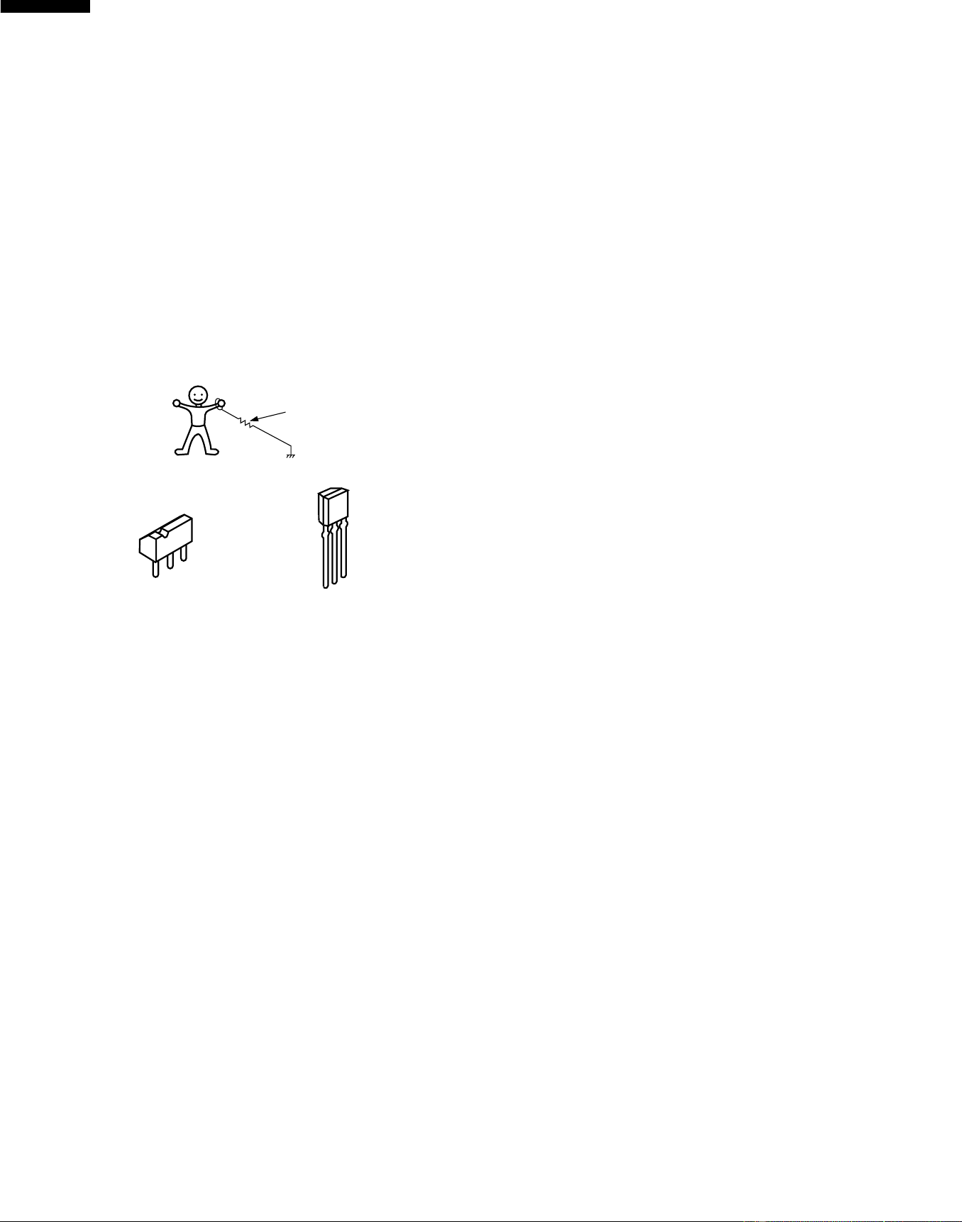
28
R-519CK
R-530CK
R-530CW
1. Precautions for Handling Electronic Components
This unit uses CMOS LSI in the integral part of the
circuits. When handling these parts, the following
precautions should be strictly followed. CMOS LSI have
extremely high impedance at its input and output
terminals. For this reason, it is easily influenced by the
surrounding high voltage power source, static electricity
charge in clothes, etc. and sometimes it is not fully
protected by the built-in protection circuit.
In order to protect CMOS LSI.
1) When storing and transporting, thoroughly wrap them in
aluminium foil. Also wrap all PW boards containing them
in aluminium foil.
2) When soldering, ground the technician as shown in the
figure and use grounded soldering iron and work table.
2. Shapes of Electronic Components
3. Servicing of Touch Control Panel
We describe the procedures to permit servicing of the
touch control panel of the microwave oven and the
precautions you must take when doing so. To perform
the servicing, power to the touch control panel is available
either from the power line of the oven itself or from an
external power source.
(1) Servicing the touch control panel with power supply
of the oven:
CAUTION:
THE HIGH VOLTAGE TRANSFORMER OF THE
MICROWAVE OVEN IS STILL LIVE DURING
SERVICING AND PRESENTS A HAZARD.
Therefore, before checking the performance of the touch
control panel,
1) Disconnect the power supply cord, and then remove
outer case.
2) Open the door and block it open.
3) Discharge high voltage capacitor.
4) Disconnect the leads to the primary of the power
transformer.
5)
Ensure that these leads remain isolated from other
components and oven chassis by using insulation tape.
6)
After that procedure, re-connect the power supply cord.
After checking the performance of the touch control panel,
1) Disconnect the power supply cord.
2) Open the door and block it open.
3) Re-connect the leads to the primary of the power
transformer.
4) Re-install the outer case (cabinet).
TOUCH CONTROL PANEL SERVICING
5) Re-connect the power supply cord after the outer
case is installed.
6) Run the oven and check all functions.
A. On some models, the power supply cord between the
touch control panel and the oven itself is so short that the
two can’t be separated. For those models, check and
repair all the controls (sensor-related ones included) of the
touch control panel while keeping it connected to the oven.
B. On some models, the power supply cord between the
touch control panel and the oven proper is long enough
that they may be separated from each other. For those
models, it is possible to check and repair the controls of
the touch control panel while keeping it apart from the
oven proper; in this case you must short both ends of the
door sensing switch (on PWB) of the touch control panel
with a jumper, which activates an operational state that
is equivalent to the oven door being closed. As for the
sensor-related controls of the touch control panel,
checking them is possible if dummy resistor(s) with
resistance equal to that of the controls are used.
(2) Servicing the touch control panel with power supply
from an external power source:
Disconnect the touch control panel completely from the
oven proper, and short both ends of the door sensing
switch (on PWB) of the touch control panel, which
activates an operational state that is equivalent to the
oven door being closed. Connect an external power
source to the power input terminal of the touch control
panel, then it is possible to check and repair the controls
of the touch control panel it is also possible to check the
sensor-related controls of the touch control panel by
using the dummy resistor(s).
4. Servicing Tools
Tools required to service the touch control panel
assembly.
1) Soldering iron: 30W
(It is recommended to use a soldering iron with a
grounding terminal.)
2) Oscilloscope: Single beam, frequency range: DC-10MHz
type or more advanced model.
3) Others: Hand tools
5. Other Precautions
1) Before turning on the power source of the control unit,
remove the aluminium foil applied for preventing static
electricity.
2) Connect the connectors of the key unit to the control unit
being sure that the lead wires are not twisted.
3) After aluminium foil is removed, be careful that abnormal
voltage due to static electricity etc. is not applied to the
input or output terminals.
4) Attach connectors, electrolytic capacitors, etc. to PWB,
making sure that all connections are tight.
5) Be sure to use specified components where high precision
is required.
E
C
B
E
C
B
Transistor
2SB1238
Transistor
KRC243M
approx. 1M ohm
Downloaded from www.ManualsFile.com manuals search engine

29
R-519CK
R-530CK
R-530CW
To remove the outer case, proceed as follows.
1. Disconnect the power supply cord.
2. Open the oven door and block it open.
3. Remove the two (2) screws from the lower portion of the
rear cabinet using a T20H Torx type or GTXH20-100
screw driver.
4. Remove the remaining two (2) screws from rear and four
(4) screws along the right side of outer case.
5. Slide the entire outer case back out about 1 inch (3 cm)
to free it from retaining clips on the cavity face plate.
6. Lift entire outer case from the unit.
Microwave ovens contain circuitry capable of producing very high voltage and current, contact with following parts may
result in severe, possibly fatal, electric shock.
(Example)
High Voltage Capacitor, Power Transformer, Magnetron, High Voltage Rectifier Assembly, High Voltage Harness etc..
WARNING:
Avoid possible exposure to microwave energy. Please follow the instructions below before
operating the oven.
WARNING AGAINST HIGH VOLTAGE:
OUTER CASE REMOVAL
COMPONENT REPLACEMENT AND ADJUSTMENT PROCEDURE
To prevent an electric shock, take the following pre-
cautions.
1. Before wiring,
1) Disconnect the power supply cord.
2) Open the door block it open.
3) Discharge the high voltage capacitor and wait for 60
seconds.
2. Don’t let the wire leads touch to the following parts;
1) High voltage parts:
Magnetron, High voltage transformer, High voltage
capacitor and High voltage rectifier assembly.
2) Hot parts:
Oven lamp, Magnetron, High voltage transformer
and Oven cavity.
WARNING FOR WIRING
1. Disconnect the power supply cord.
2. Make sure that a definite” click” can be heard when the
microwave oven door is unlatched. (Hold the door in a
closed position with one hand, then push the door open
button with the other, this causes the latch leads to rise,
it is then possible to hear a “click’ as the door switches
operate.)
3. Visually check the door and cavity face plate for damage
(dents, cracks, signs of arcing etc.).
Carry out any remedial work that is necessary before
operating the oven.
Do not operate the oven if any of the following conditions
exist;
1. Door does not close firmly.
2. Door hinge, support or latch hook is damaged.
3. The door gasket or seal is damaged.
4. The door is bent or warped.
5. There are defective parts in the door interlock system.
6. There are defective parts in the microwave generating
and transmission assembly.
7. There is visible damage to the oven.
Do not operate the oven:
1. Without the RF gasket (Magnetron).
2. If the wave guide or oven cavity are not intact.
3. If the door is not closed.
4. If the outer case (cabinet) is not fitted.
3) Sharp edge:
Bottom plate, Oven cavity, Waveguide flange,
Chassis support and other metallic plate.
4) Movable parts (to prevent a fault)
Fan blade, Fan motor, Switch, Switch lever, Open
button.
3. Do not catch the wire leads in the outer case cabinet.
4. Insert the positive lock connector until its pin is locked
and make sure that the wire leads do not come off even
if the wire leads are pulled.
5. To prevent an error function, connect the wire leads
correctly, referring to the Pictorial Diagram.
Please refer to ‘OVEN PARTS, CABINET PARTS, CONTROL PANEL PARTS, DOOR PARTS’, when carrying out any of
the following removal procedures:
Downloaded from www.ManualsFile.com manuals search engine
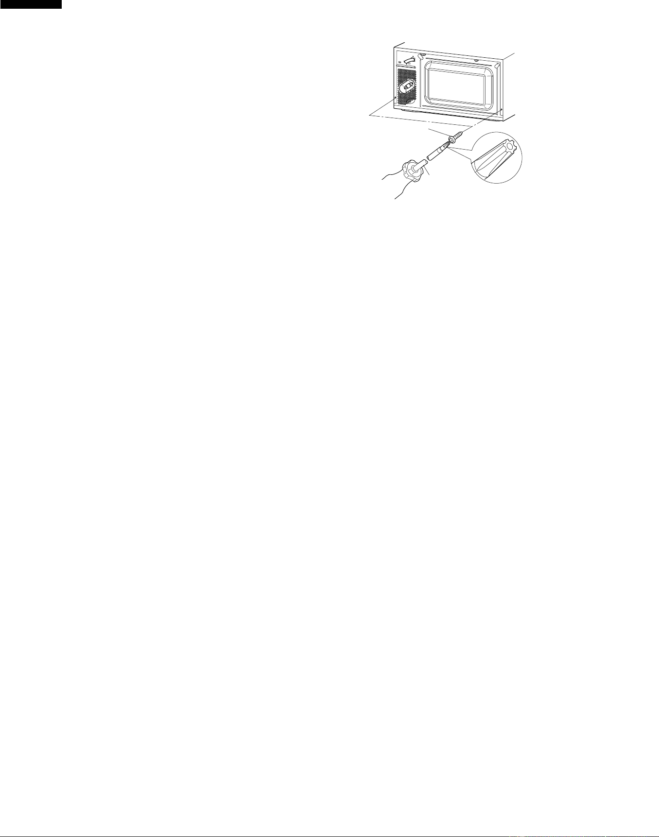
30
R-519CK
R-530CK
R-530CW
POWER TRANSFORMER REMOVAL
Re-instal
1. Rest transformer on the bottom plate with its primary
terminals toward the oven face plate.
2.
Secure transformer with four screws to bottom plate.
3. Re-connect wire leads (primary and high voltage) to
power transformer and filament leads of transformer to
magnetron and high voltage capacitor. Refer to
"PICTORIAL DIAGRAM" on page 35.
4. Re-install outer case and check that oven is operating
properly.
1. Disconnect the power supply cord and then remove
outer case.
2. Open the oven door and block it open.
3. Discharge high voltage capacitor.
4. Disconnect wire leads (primary and high voltage) from
power transformer and the filament leads from the
magnetron and capacitor terminals.
5. Remove four (4) screws holding transformer to bottom
plate.
6. Remove transformer from bottom plate.
CAUTION: 1. DISCONNECT OVEN FROM POWER SUP
PLY BEFORE REMOVING OUTER CASE.
2. DISCHARGE THE HIGH VOLTAGE CA-
PACITOR BEFORE TOUCHING ANY OVEN
COMPONENTS OR WIRING.
NOTE: When replacing the outer case, the 2 special
Torx screws must be reinstalled in the same
locations.
HIGH VOLTAGE RECTIFIER AND HIGH VOLTAGE CAPACITOR REMOVAL
1. Disconnect the power supply cord and then remove
outer case.
2. Open the door and block it open.
3. Discharge high voltage capacitor.
4. Disconnect the high voltage wire A from the high voltage
capacitor.
5. Disconnect the high voltage wire of high voltage rectifier
assembly from the magnetron.
6. Disconnect the filament lead (short one) of the power
transformer from the high voltage capacitor.
7. Remove one (1) screw holding capacitor holder with the
high voltage rectifier to the base plate.
8. Disconnect rectifier terminal from capacitor.
High voltage rectifier assembly is now free.
9. Remove capacitor holder. Capacitor is now free.
CAUTION: WHEN REPLACING HIGH VOLTAGE RECTI-
FIER AND HIGH VOLTAGE CAPACITOR,
GROUND SIDE TERMINAL OF THE HIGH
VOLTAGE RECTIFIER MUST BE SECURED
FIRMLY WITH A GROUNDING SCREW.
MAGNETRON REMOVAL
Removal
1. Disconnect the power supply cord and then remove
outer case.
2. Open the door and block it open.
3. Discharge high voltage capacitor.
4. Disconnect wire leads from magnetron.
5. Remove the two (2) screws holding the chassis support
to the magnetron and the oven cavity front flange.
6. Slide the magnetron duct slightly so that the two (2)
screws at left hand side of the magnetron appear.
7. Carefully remove the four (4) screws holding magnetron
to waveguide flange.
8. Remove the magnetron with care so that the magnetron
antenna is not hit by any metal object around the antenna.
9. Now, the magnetron is free.
Re-install
1. Re-install the magnetron to waveguide flange with care
to prevent damage to the magnetron antenna.
2. Secure the magnetron with the four (4) screws.
3. Hold the chassis support to the oven cavity front plate
and the magnetron with the two (2) screws.
4. Reconnect the wire leads to the magnetron. Refer to
"PICTORIAL DIAGRAM" on page 35.
5. Re-install outer case and check that the oven is operating
properly.
CAUTION: WHEN REPLACING MAGNETRON, BE SURE
THE R.F. GASKET IS IN PLACE AND MOUNT-
ING SCREWS ARE TIGHTENED SECURELY
Special screw
Screw Driver
(Type: TORX T20 H or
GTXH20-100)
Downloaded from www.ManualsFile.com manuals search engine
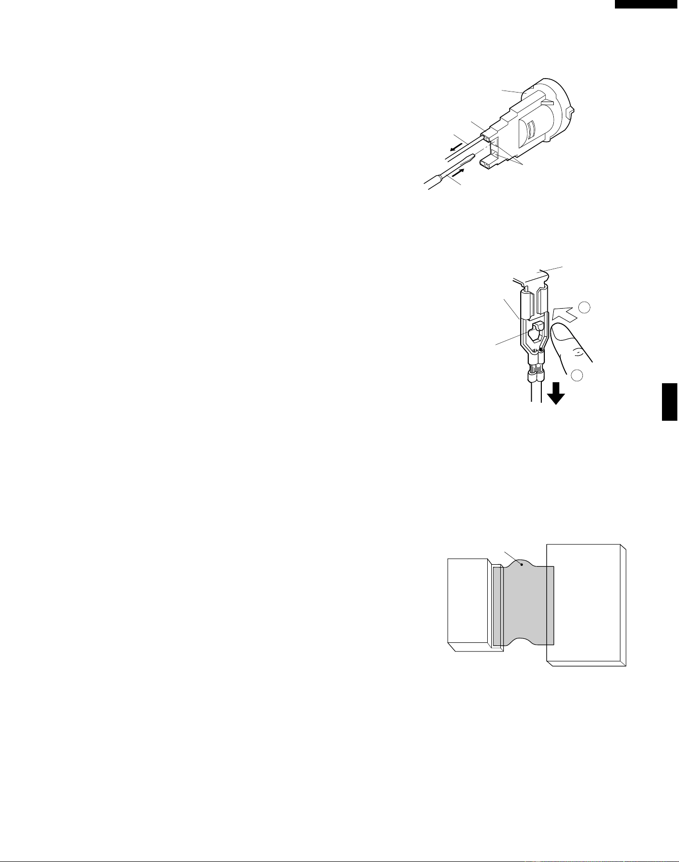
31
R-519CK
R-530CK
R-530CW
CONTROL PANEL ASSEMBLY REMOVAL
POSITIVE LOCK
®
CONNECTOR (NO-CASE TYPE) REMOVAL
Figure C-2. Positive lock
®
connector
1. Disconnect the power supply cord, and then remove
outer case.
2. Open the door and block it open.
3. Discharge high voltage capacitor.
4. Push the lever of positive lock
®
connector.
5. Pull down on the positive lock
®
connector.
CAUTION: WHEN CONNECTING THE POSITIVE LOCK
®
CONNECTORS TO THE TERMINALS, CON-
NECT THE POSITIVE LOCK
®
SO THAT THE
LEVER FACES YOU.
1. Disconnect the power supply cord and then remove
outer case.
2. Open the door and block it open.
3. Discharge high voltage capacitor.
4. Disconnect the wire leads from panel components.
5. Remove the one (1) screw holding the control panel
assembly to the oven cavity front plate.
6. Slide the control panel assembly upward and remove it.
7. Now, individual components can be removed.
NOTE: 1. Before attaching a new key unit, wipe off remaining
adhesive on the control panel frame surfaces
completely with a soft cloth soaked in alcohol.
2. When attaching the key unit to the control panel
frame, adjust the upper edge and right edge of
the key unit to the correct position of control panel
frame.
3. Stick the key unit firmly to the control panel frame
by rubbing with soft cloth so not to scratch.
LSI UNIT
NOTE: Handle the LSI unit carefully so that there is no
excessive force applied to the ribbon connection.
Oven lamp
socket
Terminal
Wire lead
Terminal hole
Flat type small
screw driver
Terminal
Push
Pull down
1
2
Lever
Positive lock®
connector
LSI unit
1. Disconnect the power supply cord.
2. Remove turntable and turntable support from oven cavity.
3. Lay the oven on it's backside. Remove the turntable
motor cover by snipping off the material in four corners.
4. Where the corners have been snipped off bend corner
areas flat. No sharp edges must be evident after removal
of the turntable motor cover.
TURNTABLE MOTOR REMOVAL
5. Disconnect wire leads from turntable motor.
(See "Positive lock connector removal")
6. Remove one (1) screw holding turntable motor to oven
cavity.
7. Now the turntable motor is free.
8. After replacement use the one (1) screw to fit the
turntable motor cover.
1.
Disconnect the power supply cord and remove outer case.
2. Open the door and block it open.
3. Discharge high voltage capacitor.
4. Remove the oven lamp from the oven lamp socket.
5. Pull the wire leads from the oven lamp socket by pushing
the terminal hole of the oven lamp socket with the small
flat type screw driver.
6. Remove the oven lamp socket from the magnetron duct
by turning the socket counterclockwise.
7. Remove the oven lamp from the socket by turning the
oven lamp.
8. Now, the oven lamp and the oven lamp socket are free.
OVEN LAMP AND LAMP SOCKET REMOVAL
Figure C-1. Oven lamp socket
Printed wiring board
of LSI unit
Liquid Crystal
Display (LCD)
Ribbon cable
Downloaded from www.ManualsFile.com manuals search engine
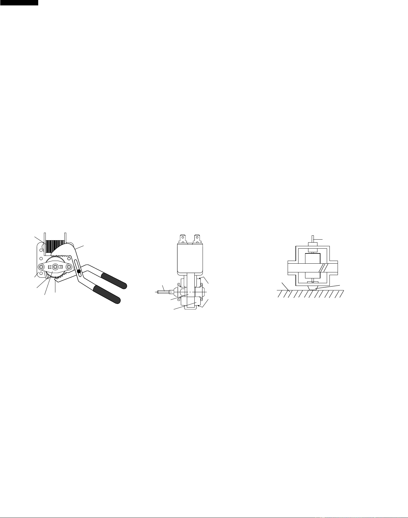
32
R-519CK
R-530CK
R-530CW
COOLING FAN MOTOR REMOVAL
REMOVAL
1. Disconnect the power supply cord and then remove
outer case.
2. Open the door and block it open.
3. Discharge high voltage capacitor.
4. Disconnect the wire leads from the fan motor.
5. Remove the two (2) screws holding the fan motor to the
oven cavity back plate.
6. Remove the fan blade from the fan motor shaft according
to the following procedure.
7. Hold the edge of the rotor of the fan motor by using a pair
of groove joint pliers.
CAUTION:
* Make sure that no metal pieces enter the gap between
the rotor and the stator of the fan motor because the
rotor is easily shaven by pliers and metal pieces may
be produced.
* Do not touch the pliers to the coil of the fan motor
because the coil may be cut or damaged.
* Do not disfigure the bracket by touching with the
pliers.
8. Remove the fan blade from the shaft of the fan motor by
pulling and rotating the fan blade with your hand.
9. Now, the fan blade and the fan motor will be free.
CAUTION:
* Do not reuse the removed fan blade because the
hole (for shaft) may be larger than normal.
INSTALLATION
1. Install the fan blade to the fan motor shaft according to
the following procedure.
2. Hold the center of the bracket which supports the shaft
of the fan motor on the flat table.
3. Apply the screw lock tight into the hole (for shaft) of the
fan blade.
4. Install the fan blade to the shaft of fan motor by pushing
the fan blade with a small, light weight, ball peen hammer
or rubber mallet.
CAUTION:
* Do not hit the fan blade hard when installing because
the bracket may be damaged.
* Make sure that the fan blade rotates smoothly after
installation.
* Make sure that the axis of the shaft is not slanted.
5. Install the fan motor to the the oven cavity back plate with
the two (2) screws.
6. Connect the wire leads to the fan motor, referring to the
pictorial diagram.
Side ViewRear View
Gap
Rotor
Bracket
Stator
Groove joint pliers
Coil
Shaft
Axis
Stator
Rotor
These are the positions
that should be pinched
with pliers
Shaft
Table
Center of
bracket
1.
Disconnect the power supply cord and remove outer case.
2. Open the door and block it open.
3. Discharge high voltage capacitor.
4. Disconnect wire leads from the switches.
5.
Remove two (2) screws holding latch hook to oven flange.
6. Remove latch hook assembly from oven flange.
7. Push outward on the two (2) retaining tabs holding switch
in place.
8. Switch is now free.
At this time switch lever will be free, do not lose it.
Re-install
1. Re-install each switch in its place. The secondary
interlock/monitor switches are in the lower position and
the door sensing switch is in the upper position.
2. Re-connect wire leads to each switch.
Refer to pictorial diagram.
DOOR SENSING SWITCH/SECONDARY INTERLOCK SWITCH AND MONITOR SWITCH REMOVAL
AH SENSOR REPLACEMENT
Removal
1. Disconnect the power supply cord, and then remove
outer case.
2. Open the door and block it open.
3. Discharge high voltage capacitor.
4. Remove the two (2) screws holding the AH sensor to the
sensor duct.
5. Disconnect the AH sensor harness from the connector
CN-F on control unit.
6. AH sensor is now free.
Removal
1. Insert the new AH sensor into the sensor duct.
2. Install two (2) screws to secure the AH sensor.
3. Route the AH sensor harness across the oven cavity top
plate and through the large opening.
4. Connect the AH sensor harness to CN-F on control unit.
5. Re-install the outer case cabinet and check for proper
operation.
Downloaded from www.ManualsFile.com manuals search engine
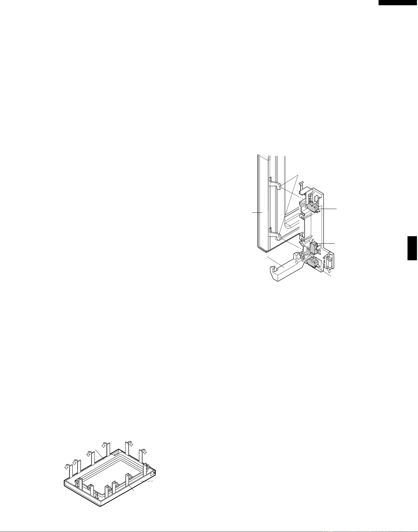
33
R-519CK
R-530CK
R-530CW
DOOR REPLACEMENT
1. Disconnect the power supply cord, and then remove
outer case.
2. Open the door and block it open.
3. Discharge high voltage capacitor.
If the door sensing switch, secondary interlock switch and
monitor switch do not operate properly due to a
misadjustment, the following adjustment should be made.
4. Loosen the two (2) screws holding latch hook to the oven
cavity front flange.
5. With door closed, adjust latch hook by moving it back and
forth, and up and down. In and out play of the door
allowed by the upper and lower position of the latch hook
should be less than 0.5mm. The vertical position of the
latch hook should be adjusted so that the door sensing
switch and secondary interlock switch are activated with
the door closed. The horizontal position of the latch hook
should be adjusted so that the plunger of the monitor
switch is pressed with the door closed.
6. Secure the screws with washers firmly.
7. Check the operation of all switches. If each switch has
not activated with the door closed, loosen screw and
adjust the latch hook position.
After adjustment, check the following.
1. In and out play of door remains less than 0.5mm when in
the latched position. First check upper position of latch
hook, pushing and pulling upper portion of door toward
the oven face. Then check lower portion of the latch
hook, pushing and pulling lower portion of the door
toward the oven face. Both results (play in the door)
should be less than 0.5mm.
2. The door sensing switch and secondary interlock switch
interrupt the circuit before the door can be opened.
3. Monitor switch contacts close when door is opened.
4. Re-install outer case and check for microwave leakage
around door with an approved microwave survey meter.
(Refer to Microwave Measurement Procedure.)
Figure C-3. Latch Switch Adjustments
REMOVAL
1. Disconnect the power supply cord.
2. Push the open button and open the door slightly.
3. Insert a putty knife (thickness of about 0.5mm) into the
gap between the choke cover and door frame as shown
in Figure C-4 to free engaging parts.
4. Pry the choke cover by inserting a putty knife as shown
Figure C-4.
5. Release choke cover from door panel.
6. Now choke cover is free.
7. Release two (2) pins of door panel from two (2) holes of
upper and lower oven hinges by lifting up.
8. Now, door panel with door frame is free from oven cavity.
Figure C-4. Door Disassembly
9. Release the door panel from twelve (12) tabs of door
frame.
10.Remove the door panel from the door frame.
11.Now, door panel with sealer film is free.
12.Tear sealer film from door panel.
13.Now, door panel is free.
14.Slide latch head upward and remove it from door frame
with releasing latch spring from door frame and latch
head.
15.Now, latch head and latch spring are free.
16.Remove door screen from door frame
17.Now, door frame is free.
RE-INSTALL
1. Re-install door screen to door frame.
2. Re-install the latch spring to the latch head. Re-install the
latch spring to the door frame. Re-install latch head to
door frame.
3. Re-install door panel to door frame by fitting twelve (12)
tabs of door frame to twelve (12) holes of door panel.
4. Put sealer film on door panel. Refer to “Sealer Film”
about how to handle new one.
5. Catch two (2) pins of door panel on two (2) hole of upper
and lower oven hinges.
Door Sensing
Switch
Monitor Switch
Switch Lever
Secondary Interlock
Switch
Latch Heads
Door
Choke Cover
Door Frame
Putty Knife
3. Secure latch hook (with two (2) mounting screws) to
oven flange.
4. Make sure that the monitor switch is operating properly
and check continuity of the monitor circuit. Refer to
chapter "Test Procedure" and Adjustment procedure.
DOOR SENSING SWITCH/SECONDARY INTERLOCK SWITCH AND MONITOR SWITCH ADJUSTMENT
Downloaded from www.ManualsFile.com manuals search engine
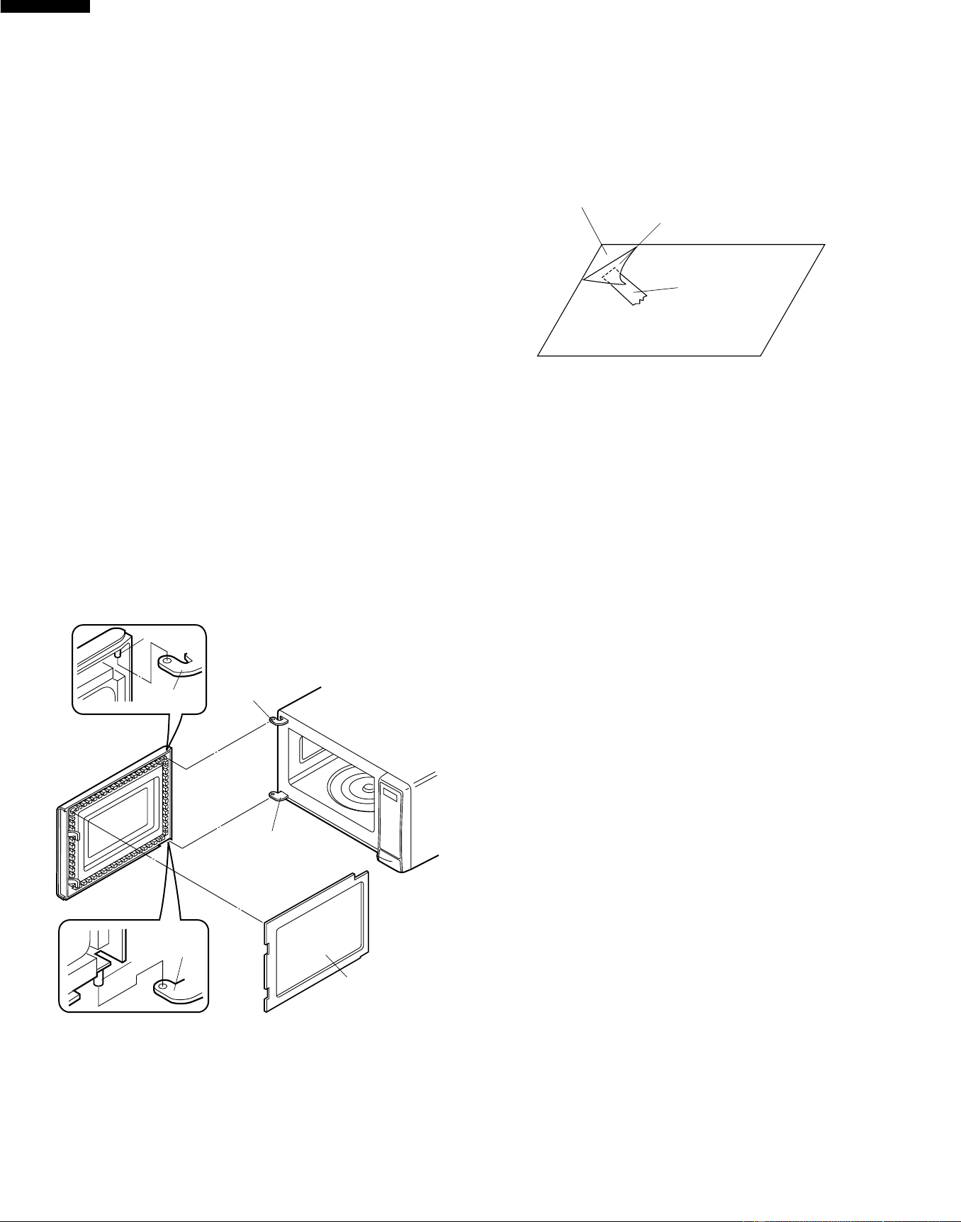
34
R-519CK
R-530CK
R-530CW
6. Re-install choke cover to door panel by pushing.
Note: After any service to the door;
(A) Make sure that door sensing switch and secondary
interlock switch are operating properly. (Refer to
chapter “Test Procedures”.).
(B) An approved microwave survey meter should be
used to assure compliance with proper microwave
radiation emission limitation standards.
After any service, make sure of the following :
1. Door latch heads smoothly catch latch hook through
latch holes and that latch head goes through center of
latch hole.
2. Deviation of door alignment from horizontal line of cavity
face plate is to be less than 1.0mm.
3. Door is positioned with its face pressed toward cavity
face plate.
4. Check for microwave leakage around door with an
approved microwave survey meter. (Refer to Microwave
Measurement Procedure.)
Note: The door on a microwave oven is designed to act as
an electronic seal preventing the leakage of
microwave energy from oven cavity during cook
cycle. This function does not require that door be air-
tight, moisture (condensation)-tight or light-tight.
Therefore, occasional appearance of moisture, light
or sensing of gentle warm air movement around
oven door is not abnormal and do not of themselves
indicate a leakage of microwave energy from oven
cavity.
Figure C-5. Door Replacement
Sealer film
Backing film
Adhesive tape
Pin
Pin
Upper
Oven Hinge
Upper Oven
Hinge
Lower Oven
Hinge
Lower
Oven Hinge
Choke Cover
SEALER FILM
Installation
1. Put the adhesive tape on the backing film of the sealer
film as shown in Fig. C-6.
2. Tear the backing film by pulling the adhesive tape.
3. Put the pasted side of the sealer film on the door panel
Figure C-6. Sealer film
Downloaded from www.ManualsFile.com manuals search engine
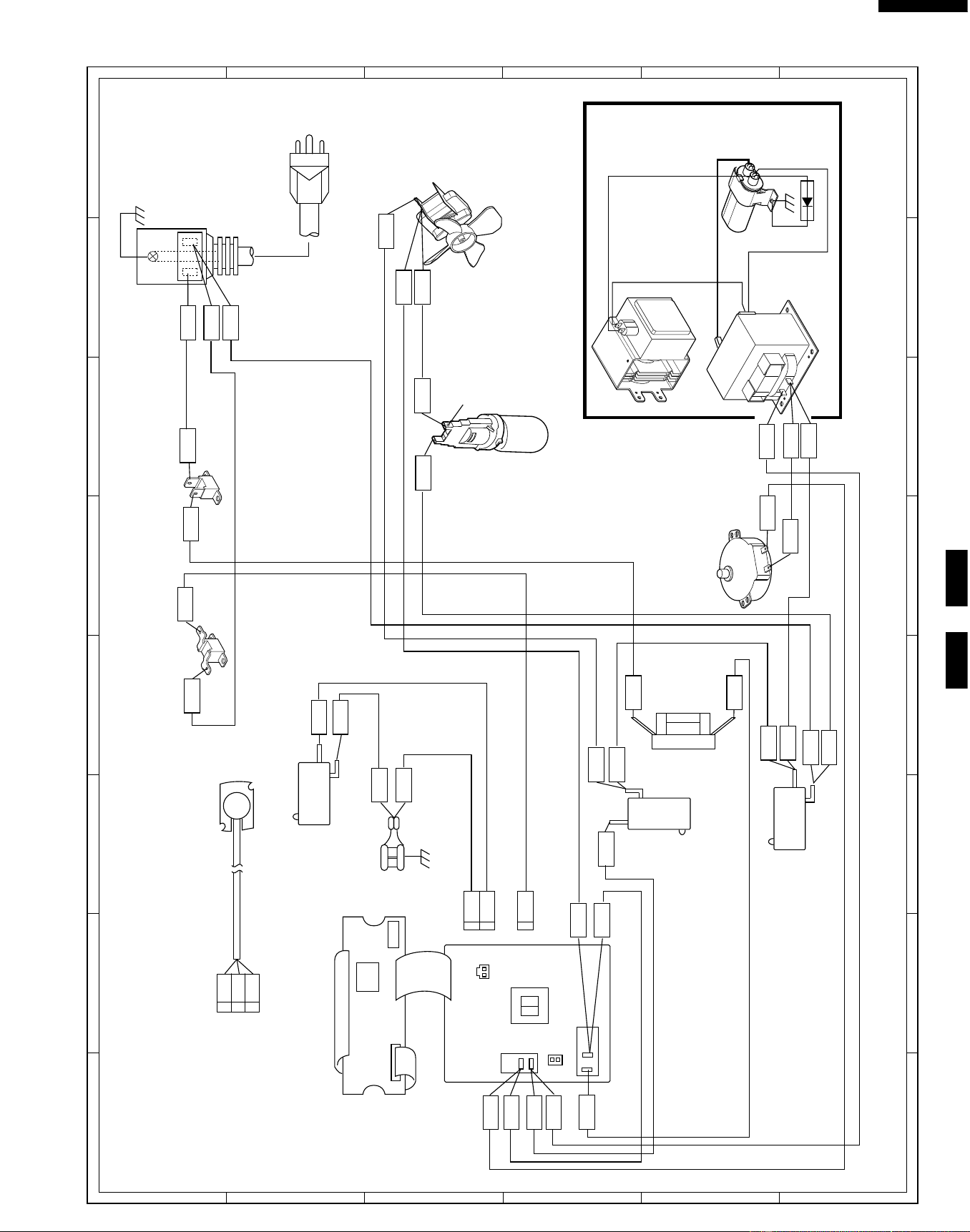
35
R-519CK
R-530CK
R-530CW
6
45
1
2
3
6
45
1
2
3
A
B
C
D
E
F
G
H
A
B
C
D
E
F
G
H
Figure S-1. Pictorial Diagram
HIGH
VOLTAGE
CAPACITOR
HIGH VOLTAGE
WIRE A
H.V. RECTIFIER
POWER SUPPLY
CORD 120V 60Hz
HIGH VOLTAGE COMPONENTS
OVEN LAMP
AND SOCKET
MAGNETRON
COM.
MONITOR
SWITCH
COM.
N.O.
N.C.
DOOR
SENSING
SWITCH
SECONDARY
INTERLOCK
SWITCH
TURNTABLE
MOTOR
NOTE:
Hot (ORG) wire must be
connected to the terminal
with blue mark on the oven
light socket.
POWER
TRANSFORMER
COM.
NO
NOTE:
The neutral (WHT/GRY) wire must
be connected to the terminal with
"N" mark on the power supply
cord.
RED
WHT
RED
WHT
WHT
ORG
WHT
PNK
GRN
GRN
to Oven cavity
WHT
WHT
RED
BLK
WHT
WHT
BLUE MARK
WHT
RED
WHT
CAVITY TEMP. FUSE
MAGNETRON TEMP. FUSE
FAN MOTOR
MONITOR
FUSE
&
HOLDER
RED
RED
WHT
1
WHT
GRY
WHT
GRN
ORG
ORG
CN-A
H
N
NOTE:
The grounding conductor of
the power supply cord has
been grounded by power
supply cord fixing screw.
The screw must always be
kept tight.
GRY
PNK
GRN
2
1
CN-B
CN-B
BRN
WHT
BLK
BLU
ORG
B LU
BRN
RED
RED
BLK
AH SENSOR
RED
WHT
1
2
3
CN-F
N.O.
N.O.
COM.
RY2
PRIMARY
INTERLOCK
RELAY
CN-A
T1
1
1
2
2
CONTROL PANEL
(LSI UNIT)
(POWER UNIT)
CN-F
CN-C
CN-G
Downloaded from www.ManualsFile.com manuals search engine
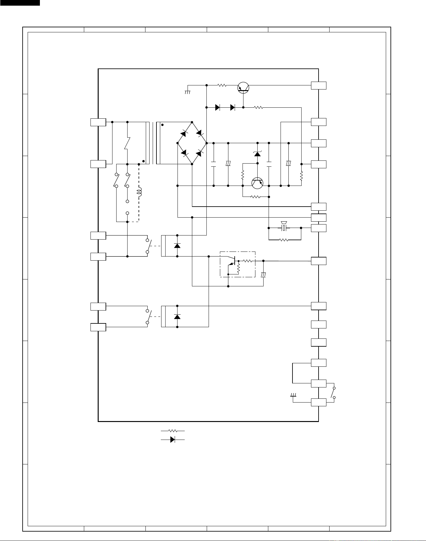
36
R-519CK
R-530CK
R-530CW
6
45
1
2
3
6
45
1
2
3
A
B
C
D
E
F
G
H
A
B
C
D
E
F
G
H
Figure S-2. Power Unit Circuit
+
–
+
–
A 1
A 2
C 1
C10
C 2
C 3
C 4
C 9
C 5
C 7
B 1
C12
C11
B 2
T1
AC120V
60Hz
MICRO
VA
LED
GND
VC
INT
VR
BUZZER
MICRO
N.C.
C 8
N.C.
DOOR
SENSING
SWITCH
DOOR
SWITCH
C 6
NOTE
: IF NOT SPECIFIED, 1/4W ± 5%
: IF NOT SPECIFIED, 1SS270A
TURNTABLE
MOTOR
OVEN LAMP
FAN
MOTOR
TURNTABLE
MOTOR
OVEN LAMP
FAN
MOTOR
R4 27
R5 4.7k
R2 680 1/2w
2SB1238
Q1
R3 510
1/2w
R1 2.4k
ZD1
HZ16-1
R6 3.3k
SP1
VRS1
C1 0.1µ/50v
C3 0.1µ/50v
C5
10µ/35v
C2 1000µ/35v
+
–
C4 10µ/35v
(J1)
D5
D3
D4
D2
D1
a
c
d
b
D6
RY1
D7
D8
RY2
Q2 2SB1238
D1-D4
11ES1
Q3 KRC243M
N.O.
N.O.
COM
COM
14
36
Downloaded from www.ManualsFile.com manuals search engine
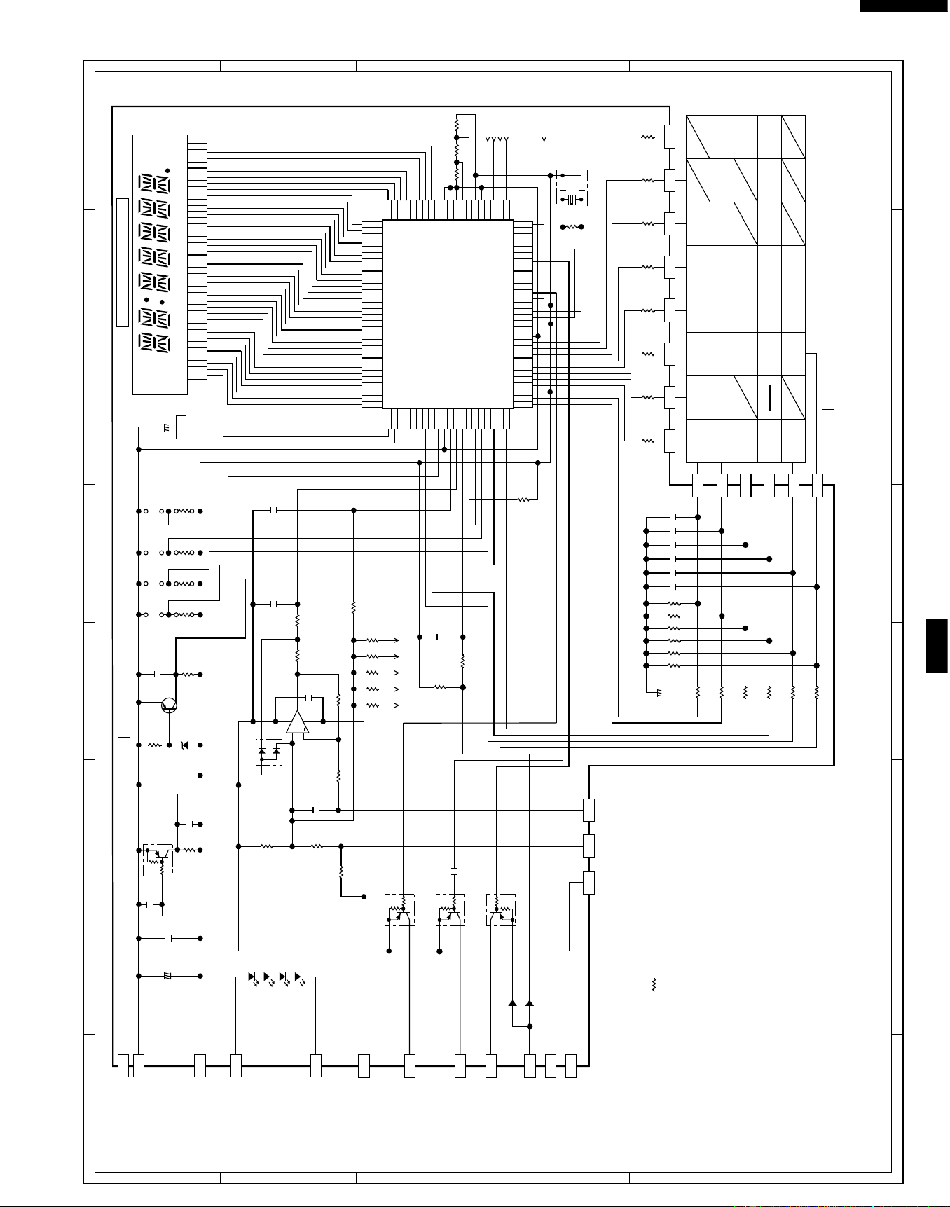
37
R-519CK
R-530CK
R-530CW
6
45
1
2
3
6
45
1
2
3
A
B
C
D
E
F
G
H
A
B
C
D
E
F
G
H
Figure S-3. CPU Unit Circuit For R-519CK
+
–
C-2
C-3
C-10
C-9
C-1
C-5
C-6
C-7
C-12
C-8
F-1
G 9
G10
G11
G12
G13
G14
G 8
54321
0
Minute
Plus
Clock START
Ground Meat
(COMPU DEFROST)
Ground Meat
(SENSOR COOK)
CUSTOM
HELP
Frozen
Entrees
Reheat
Stop
Clear
Frozen
Rolls/
Muffins
Fresh
Rolls/
Muffins
Beverage
Power
Level
Fish/
Seafood
Frozen
Vegetables
Fresh
Vegetables
Baked
Potatoes
Kitchen
Timer
Chicken
Pieces
Steaks/
Chops
Popcorn
9876
G 7 G 6 G 5 G 4 G 3 G 2 G 1
F-2 F-3
C-11
C-4
INT
GND
CPU UNIT
VC
LED
VR
VA
MICRO
DOOR
(BROWNER)
NOTE
NC
: IF NOT SPECIFIED, 1/10W ± 5%
AH SENSOR
BUZZER
OVEN LAMP
TURNTABLE
MOTOR
FAN MOTOR
IC1
IZA966DR
C10 47µ/16v
C11 0.1µ/50v
C40
0.01µ/25v
C65 330pF/50v
C64 330pF/50v
C63 330pF/50v
C62 330pF/50v
C61 330pF/50v
C60 330pF/50v
C12
0.1µ
/50v
C13
0.01µ
/25v
C92
0.01µ/25v
C93
0.01µ/25v
C91
0.015µ/25v
C14
0.01µ/25v
C90
0.1µ/50v
C20
0.1µ/50v
ZD10
UDZ4.3B
R12
15k
R96 3.57kDR91 3.32kD
R11
15k
C110
4.7k
(J10)
(J11)
4.7k
(J13)
4.7k
(J15)
4.7k
(J12)
(J14)
(J17)
4.7k
(J16)
D90
MA152WA
Q30
DTA143EKA
Q20
DTA143EKA
Q11
DTA143EKA
Q21 DTA123JKA
D20 1SS355
D41 1SS355
IC2
BA4558
IC2
+
4
6
5
8
7
LD4 LD3 LD2 LD1
R90 330 1w
R94 10k
CF1
CST4.00MGW
E
E
D
C
B
A
DCBA
R92 1.8kF
R78 270k
R79 270k
R77 270k
R76 270k
R75 270k
R74 270k
R41 15k
R68 15k
R69 15k
R70 15k
R71 15k
R72 15k
R73 15k
R93 360kF
R95 47k
R97 47k
R13
10k
R14
10k
130
31
50
5180
81
100
R15
10k
R101 75kF
R102 37.4kF
R100 150kF
R99 300k
R98 620k
Q10
2SA1037AK
R10 1k
R80
1M
R66 15k
R65 15k
R64 15k
R63 15k
R62 15k
R61 15k
R60 15k
R67 15k
R40 4.7k
SEG35
SEG34
SEG33
SEG32
SEG31
SEG30
SEG29
SEG28
SEG27
SEG26
SEG25
SEG24
SEG23
SEG22
SEG21
AN10
AN11
AVSS
P10
P11
P12
P13
P14
P15
P16
P17
X 1
X 2
VSS
OSC2
OSC1
TEST
RES
P20
P21
P22
P23
P24
P25
P26
P27
P30
P31
P32
P33
SEG20
SEG35
SEG34
SEG33
SEG32
SEG31
SEG30
SEG29
SEG28
SEG27
SEG26
SEG25
SEG24
SEG23
SEG22
SEG21
SEG20
SEG19
SEG18
SEG17
SEG16
SEG15
SEG14
SEG13
SEG12
SEG11
SEG10
SEG9
SEG8
SEG7
SEG6
SEG5
SEG4
SEG3
SEG2
SEG1
SEG0
COM0
COM1
COM2
SEG5
SEG36
SEG37
SEG38
SEG39
SEG40
P40
P41
P42
IRQ0
AVCC
AN0
AN1
AN2
AN3
AN4
AN5
AN6
AN7
AN8
AN9
SEG4
SEG3
SEG2
SEG1
COM1
COM2
COM3
COM4
VCC
V 0
V 1
V 2
V 3
VSS
CVCC
P37
P36
P35
P34
SEG19
SEG18
SEG17
SEG16
SEG15
SEG14
SEG13
SEG12
SEG11
SEG10
SEG9
SEG8
SEG7
SEG6
LIQUID CRYSTAL DISPLAY
COOK SENSOR LBS DEF HELP
KEY UNIT
GND
Downloaded from www.ManualsFile.com manuals search engine
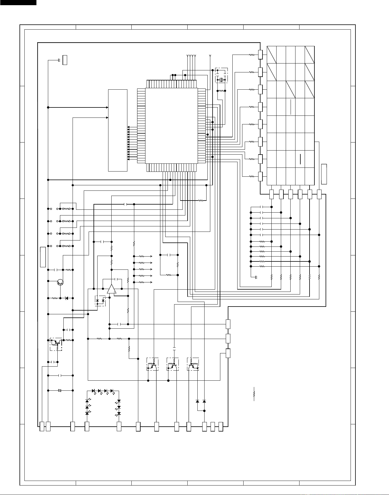
38
R-519CK
R-530CK
R-530CW
6
45
1
2
3
6
45
1
2
3
A
B
C
D
E
F
G
H
A
B
C
D
E
F
G
H
Figure S-4. CPU Unit Circuit For R-530CK/CW
+
–
C-2
C-3
C-10
C-9
C-1
C-5
C-6
C-7
C-12
C-8
F-1
G 9
G10
G11
G12
G13
G14
G 8
54321
0
Minute
Plus
Frozen
snacks
Clock
Sensor
reheat
Baked
potatoes
Custom
Help
Super
Defrost
Stop
Clear
One Dish
Dinners
Lunch on
the Run
Power
Level
Breakfast
Bar
Fish/
seafood
Frozen
vegetables
Frozen
entrees
Fresh
vegetables
Ground
meat
Kitchen
Timer
Beverage
Center
Compu
Defrost
Rice
Poultry
Popcorn
9876
G 7 G 6 G 5 G 4 G 3 G 2 G 1
F-2
F-3
C-11
C-4
INT
GND
CPU UNIT
VC
LED
VR
VA
MICRO
DOOR
(BROWNER)
NOTE
NC
: IF NOT SPECIFIED, 1/10W ± 5%
AH SENSOR
BUZZER
OVEN LAMP
TURNTABLE
MOTOR
FAN MOTOR
IC1
IZA950DR
Indicator Circuit
( See Fig. S-5 )
C10 47µ/16v
C11 0.1µ/50v
C40
0.01µ/25v
C65 330pF/50v
C64 330pF/50v
C63 330pF/50v
C62 330pF/50v
C61 330pF/50v
C60 330pF/50v
C12
0.1µ
/50v
C13
0.01µ
/25v
C92
0.01µ/25v
C93 0.01µ/25v
C91
0.015µ/25v
C14
0.01µ/25v
C90
0.1µ/50v
C20
0.1µ/50v
ZD10
UDZ4.3B
R12
15k
R96 3.57kDR91 3.32kD
R11
15k
C110
4.7k
(J10)
(J11)
4.7k
(J13)
4.7k
(J15)
4.7k
(J17)
4.7k
(J12)
(J14)
(J16)
D90
MA152WA
Q30
DTA143EKA
Q11
DTA143EKA
Q20
DTA143EKA
Q21 DTA123JKA
D20 1SS355
D41 1SS355
IC2
BA4558
IC2
+
4
6
5
8
7
LD10
LD19 LD18 LD17
LD11 LD12
LD16 LD15 LD14 LD13
R90 330 1w
R94 10k
CF1
CST4.00MGW
E
E
D
C
B
A
DCBA
R92 1.8kF
R78 270k
R79 270k
R77 270k
R76 270k
R75 270k
R74 270k
R41 15k
130
31
50
5180
81
100
R68 15k
R69 15k
R70 15k
R71 15k
R72 15k
R73 15k
R93 360kF
R95 47k
R97 47k
R102 37.4kF
R101 75kF
R100 150kF
R99 300k
R98 620k
Q10
2SA1037AK
R10 1k
R80
1M
R66 15k
R65 15k
R64 15k
R63 15k
R62 15k
R61 15k
R60 15k
R67 15k
R40 4.7k
SEG35
AN10
AN11
AVSS
P10
P11
P12
P13
P14
P15
P16
P17
X 1
X 2
VSS
OSC2
OSC1
TEST
RES
P20
P21
P22
P23
P24
P25
P26
P27
P30
P31
P32
P33
P91
P90
P87
P86
P85
P84
P83
P76
P75
P74
SEG20
SEG5
SEG36
SEG37
SEG38
SEG39
SEG40
P40
P41
P42
IRQ0
AVCC
AN0
AN1
AN2
AN3
AN4
AN5
AN6
AN7
AN8
AN9
SEG4
SEG3
SEG2
SEG1
COM1
COM2
COM3
COM4
VCC
V 0
V 1
V 2
V 3
VSS
CVCC
P37
P36
P35
P34
SEG19
SEG18
SEG17
SEG16
SEG15
SEG14
SEG13
SEG12
SEG11
SEG10
SEG9
SEG8
SEG7
SEG6
P82
P81
P80
P77
Start
Touch On
KEY UNIT
GND
Downloaded from www.ManualsFile.com manuals search engine
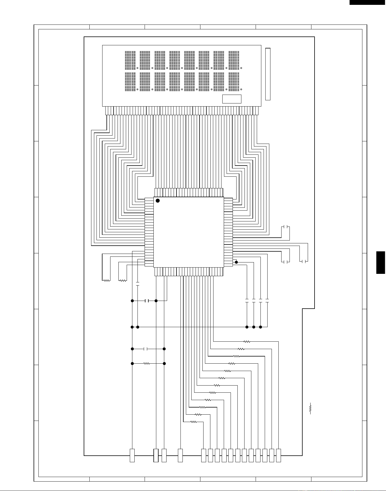
39
R-519CK
R-530CK
R-530CW
6
45
1
2
3
6
45
1
2
3
A
B
C
D
E
F
G
H
A
B
C
D
E
F
G
H
Figure S-5. Indicator Circuit For R-530CK/CW
VC
GND
IC1 P91
OSC4
VC1
VC2
VC3
VC4
VC5
CF
CE
CD
CC
CB
CA
COM8
COM9
COM10
COM11
COM12
COM13
COM14
COM15
COM16
SEG39
SEG38
SEG37
SEG36
SEG35
OSC3
VD1
OSC2
OSC1
VSS
BZ
COM0
COM1
COM2
COM3
COM4
COM5
COM6
COM7
SEG0
SEG1
SEG2
SEG3
SEG4
SEG5
SEG6
SEG7
SEG8
SEG10
COM16
COM15
COM14
COM13
COM12
COM11
COM10
COM9
SEG40
SEG39
SEG38
SEG37
SEG36
SEG35
SEG34
SEG33
SEG32
SEG31
SEG30
SEG29
SEG28
SEG27
SEG26
SEG25
SEG24
SEG23
SEG22
SEG21
SEG20
SEG19
SEG18
SEG17
SEG16
SEG15
SEG14
SEG13
SEG12
SEG11
SEG10
SEG9
SEG8
SEG7
SEG6
SEG5
SEG4
SEG3
SEG2
SEG1
COM1
COM2
COM3
COM4
COM5
COM6
COM7
COM8
VDD
NC
NC
RESET
TEST
VREF
R03
R02
R01
R00
P13
P12
P11
P10
P03
P02
P01
P00
K03
K02
K01
K00
NC
NC
NC
SEG11
SEG12
SEG13
SEG14
SEG15
SEG16
SEG17
SEG18
SEG19
SEG20
SEG21
SEG22
SEG23
SEG24
SEG25
SEG26
SEG27
SEG28
SEG29
SEG30
SEG31
SEG32
SEG33
SEG34
SEG9
1
100
76
7551
25
IC3
IZA951DR
26
50
R134 15k
R132 33k R133 510k
R120 4.7k
R121 4.7k
R122 4.7k
R123 4.7k
R124 4.7k
R125 4.7k
R126 4.7k
R127 4.7k
R128 4.7k
R129 4.7k
R130 4.7k
R131 4.7k
C124 0.1µ/50v
C120 0.1µ/50v
C121 0.1µ/50v
C122 0.1µ/50v
C123 0.1µ/50v
C126
0.1µ/50v
C125
0.1µ/50v
C127
0.1µ/50v
C129
0.1µ/50v
C128
0.1µ/50v
IC1 P90
IC1 P86
IC1 P85
IC1 P84
IC1 P83
IC1 P82
IC1 P81
IC1 P80
IC1 P77
IC1 P76
IC1 P75
IC1 P74
IC1 P87
NOTE
: IF NOT SPECIFIED, 1/10W ± 5%
SENSOR DEFROST COOK HELP
LIQUID CRYSTAL DISPLAY
Downloaded from www.ManualsFile.com manuals search engine
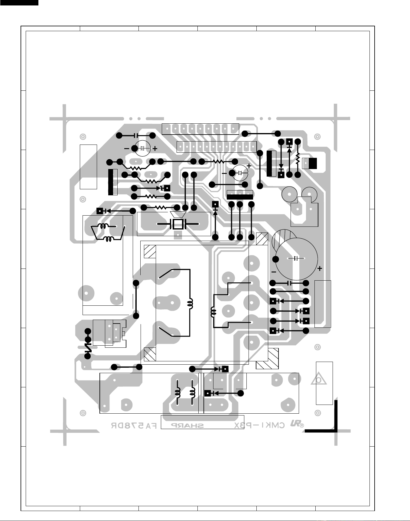
40
R-519CK
R-530CK
R-530CW
6
45
1
2
3
6
45
1
2
3
A
B
C
D
E
F
G
H
A
B
C
D
E
F
G
H
Figure S-6. Printed Wiring Board of Power Unit
WH - 1
SH - B
SH - A
1
C3
C4
C5
R3
C2
F
C1
10
D4
D2
D1
D3
(J1)
D9
(D10)
RY3
(CN - D)
D8
ZD1
VRB
DU
R2
R1
R6
R5
SP1
3
E
B
D6
D5
Q2
R4
2
6
11
P
S
RY2
T1
AC
VRS1
QKITPB026MRE0
5
D7
OMIF
DU
9
8
7
E
Q1
B
4
E
RY1
AC
OL
TTM
FM
B
Q3
(CN - C)
CN - C
CN - B
CN - A
1
1
9
12
1
1
12
XA
VH
2
2
Downloaded from www.ManualsFile.com manuals search engine
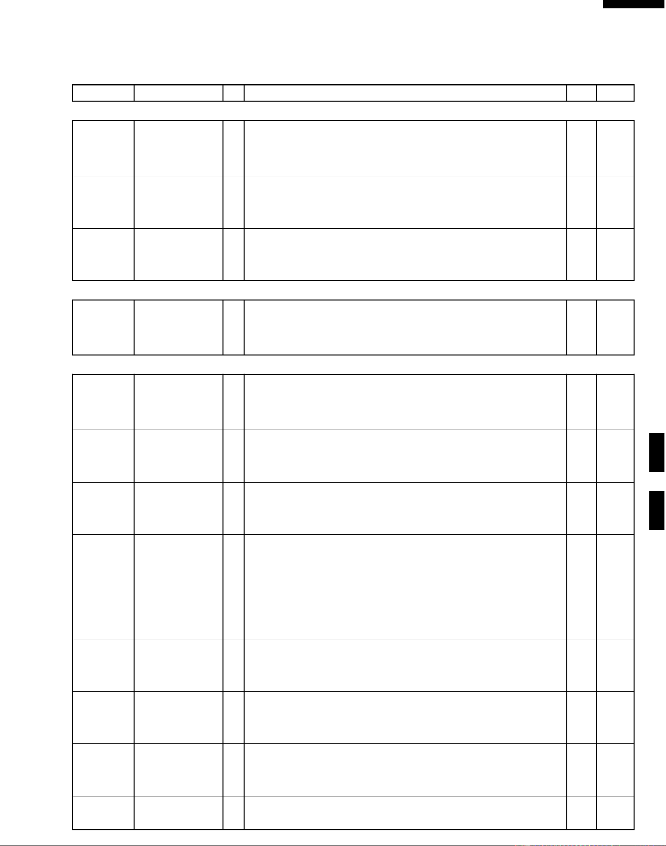
41
R-519CK
R-530CK
R-530CW
REF. NO. PART NO. § DESCRIPTION Q'TY CODE
PARTS LIST
Note: The parts marked “∆” may cause undue microwave exposure.
The parts marked “*” are used in voltage more than 250V. "§" MARK: PARTS DELIVERY SECTION.
*
*
*
∆
*
ELECTRIC PARTS
1- 1 RC-QZB018MRE0 M High voltage capacitor 1 AQ
1- 2 FH-DZB008MRY0 M High voltage rectifier assembly 1 AM
1- 3 QSOCLB006MRE0 M Oven lamp socket 1 AE
1- 4 RLMPTA068WRE0 M Oven lamp 1 AE
1- 5 RMOTEA346WRE0 M Fan motor 1 AR
1- 6 QFSHDB003MRE0 M Fuse holder 1 AD
1- 7 FFS-BA016/KIT M
Monitor switch (V-16G-2C25) and fuse assembly (20A 250V AC)
1AF
1- 8 QSW-MA085WRE0 M
Secondary interlock switch and door sensing switch (V-16G-3C25)
2AE
1- 9 QFS-TA013WRE0 M Magnetron temperature fuse 150˚C 1 AE
1-10 QFS-TA014WRE0 M Cavity temperature fuse150˚C 1 AF
1-11 RV-MZA255WRE0 M Magnetron 1 BE
1-12 RMOTDA182WRE0 M Turntable motor 1 AP
1-13 RTRN-B061MRE0 M Power transformer 1 BD
1-14 FACCDB003WRE0 M Power supply cord 1 AM
1-15 FDTCTA198WRK0 M AH sensor 1 AN
CABINET PARTS
2- 1 GDAI-B054MRP0 M Base plate 1 BC
2- 2 GLEGPB004MRF0 M Foot 4 AB
2- 3 GCABUB069MRP0 M Outer case cabinet [R-519CK] 1 AY
2- 3 GCABUB083MRP0 M Outer case cabinet [R-530CK] 1 AX
2- 3 GCABUB089MRP0 M Outer case cabinet [R-530CW] 1 AY
CONTROL PANEL PARTS
3- 1 CPWBFB031MRU0 M Control unit [R-519CK] 1 BL
3- 1 CPWBFB032MRU0 M Control unit [R-530CK] 1 BL
3- 1 CPWBFB032MRU0 M Control unit [R-530CW] 1 BL
3- 1A QCNCMA446DRE0 J 2-pin connector (CN-A) 1 AC
3- 1B QCNCMA275DRE0 J 2-pin connector (CN-B) 1 AB
3- 1C FW-VZB146MRE0 M 12P wire harness (CN-C) 1 AG
C1 RC-KZA087DRE0 J Capacitor 0.1 uF 50V 1 AA
C2 VCEAB31VW108M J Capacitor 1000 uF 35V 1 AF
C3 RC-KZA087DRE0 J Capacitor 0.1 uF 50V 1 AA
C4-5 VCEAB31VW106M J Capacitor 10 uF 35V 2 AA
D1-4 VHD11ES1///-1 J Diode (11ES1) 4 AB
D5-8 VHD1SS270A/-1 J Diode (1SS270ATA) 4 AA
Q1-2 VS2SB1238//-3 J Transistor (2SB1238) 2 AA
Q3 VSKRC243M//-3 J Transistor (KRC243M) 1 AB
R1 VRD-B12EF242J J Resistor 2.4k ohm 1/4W 1 AA
R2 VRD-B12HF681J J Resistor 680 ohm 1/2W 1 AA
R3 VRD-B12HF511J J Resistor 510 ohm 1/2W 1 AB
R4 VRD-B12EF270J J Resistor 27 ohm 1/4W 1 AA
R5 VRD-B12EF472J J Resistor 4.7k ohm 1/4W 1 AA
R6 VRD-B12EF332J J Resistor 3.3k ohm 1/4W 1 AA
RY1-2 RRLY-B002MRE0 M Relay (DU24D1-1P(M)) 2 AH
RY1-2 RRLY-A113DRE0 M Relay (DU24D1-1PR(M)) (Interchangeable) 2 AG
SP1 RALM-A014DRE0 J Buzzer (PKM22EPT) 1 AG
T1 RTRNPB009MRE0 M Transformer 1 AM
VRS1 RH-VZA032DRE0 J Varistor (10G471K) 1 AE
ZD1 VHEHZ161///-1 J Zener diode (HZ16-1) 1 AA
3- 2 FPNLCB249MRK0 M Control panel frame with key unit [R-530CK] 1 AX
3- 2 FPNLCB250MRK0 M Control panel frame with key unit [R-530CW] 1 AX
3- 2 FPNLCB262MRK0 M Control panel frame with key unit [R-519CK] 1 AX
3- 2- 1 FUNTKB199MRE0 M Key unit [R-530CK] 1 AR
3- 2- 1 FUNTKB200MRE0 M Key unit [R-530CW] 1 AR
3- 2- 1 FUNTKB212MRE0 M Key unit [R-519CK] 1 AR
3- 2- 2 JBTN-B086MRF0 M Open button [R-519CK] 1 AE
3- 2- 2 JBTN-B086MRF0 M Open button [R-530CK] 1 AE
3- 2- 2 JBTN-B087MRF0 M Open button [R-530CW] 1 AE
3- 2- 3 MSPRTA050WRE0 M Open button spring 1 AA
3- 3 LHLD-B009MRF0 M LCD holder [R-519CK] 1 AF
3- 3 LHLD-B010MRF0 M LCD holder [R-530CK] 1 AF
3- 3 LHLD-B010MRF0 M LCD holder [R-530CW] 1 AF
3- 4 PSHEPA666WRE0 M LED sheet [R-530CK] 1 AF
3- 4 PSHEPA666WRE0 M LED sheet [R-530CW] 1 AF
3- 4 PSHEPB023MRE0 M LED sheet [R-519CK] 1 AR
3- 5 XEPSD30P10XS0 M Screw; 3mm x 10mm 1 AA
Downloaded from www.ManualsFile.com manuals search engine
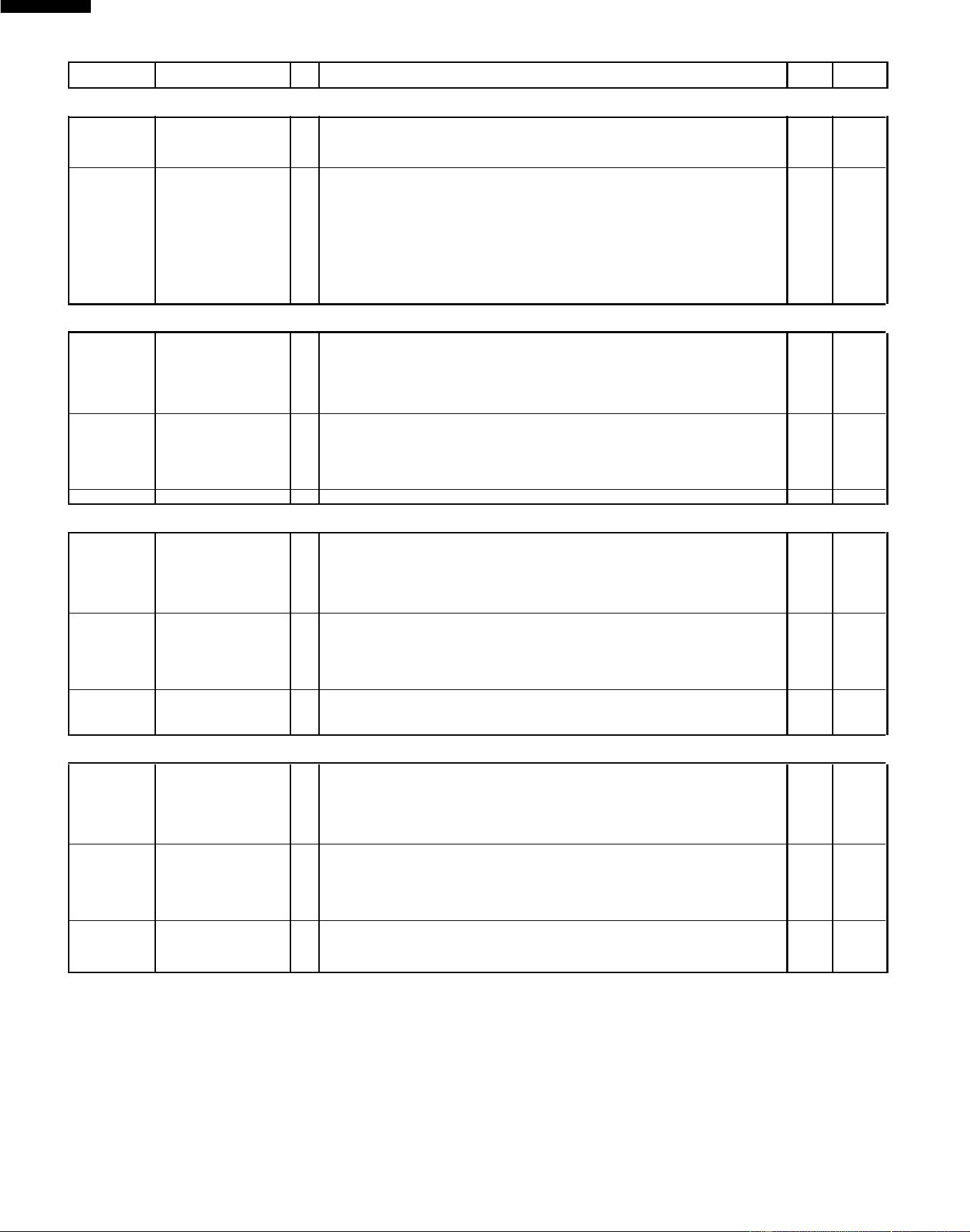
42
R-519CK
R-530CK
R-530CW
HOW TO ORDER REPLACEMENT PARTS
To have your order filled promptly and correctly, please furnish the following information.
1. MODEL NUMBER
2. REF. NO.
3. PART NO.
4. DESCRIPTION
Order Parts from the authorized SHARP parts Distributor for your area.
Defective parts requiring return should be returned as indicated in the Service Policy.
∆
∆
∆
∆
∆
*
∆
∆
REF. NO. PART NO. § DESCRIPTION Q'TY CODE
OVEN PARTS
4- 1 LBNDKB007MRP0 M H.V. Capacitor band 1 AB
4- 2 LANGTB045MRP0 M Chassis support 1 AE
4- 3 PHOK-B018MRF0 M Latch hook 1 AF
4- 4 MLEVPB016MRF0 M Switch lever 1 AD
4- 5 PDUC-B096MRF0 M Magnetron duct 1 AF
4- 6 NFANPB001MRE0 M Fan blade 1 AC
4- 7 PDUC-B088MRF0 M Fan duct 1 AC
4- 8 ------------- M Oven cavity (Not a replaceable part) 1 --
4- 9 PCOVPB082MRP0 M Waveguide cover 1 AD
4-10 PPACGB014MRF0 M Turntable motor packing 1 AA
4-11 PDUC-B091MRP0 M Sensor duct 1 AG
4-12 PCUSU0464MRE0 M Cushion 1 AC
DOOR PARTS
5- 1 FCOV-B138MRK0 M Door frame assembly [R-519CK] 1 AT
5- 1 FCOV-B138MRK0 M Door frame assembly [R-530CK] 1 AT
5- 1 FCOV-B139MRK0 M Door frame assembly [R-530CW] 1 AT
5-1-1 LSTPPB021MRF0 M Latch head 1 AE
5-1-2 MSPRTA046WRE0 M Latch spring 1 AB
5- 2 FDORFB049MRT0 M Door panel 1 AX
5- 3 PSHEPB016MREO M Sealer film 1 AD
5- 4 GCOVHB039MRF0 M Choke cover 1 AG
5- 5 HPNL-B089MRE0 M Door screen [R-519CK] 1 AK
5- 5 HPNL-B089MRE0 M Door screen [R-530CK] 1 AK
5- 5 HPNL-B090MRE0 M Door screen [R-530CW] 1 AW
MISCELLANEOUS
6- 1 FW-VZB125MRE0 M Stop switch harnes 1 AF
6- 2 FW-VZB168MRE0 M Main wire harnes 1 AU
6- 3 QW-QZB016MRE0 M High voltage wire A 1 AC
6- 4 FROLPB025MRK0 M Turntable support 1 AN
6- 5 NTNT-A099WRE0 M Turntable tray 1 AT
6- 6 TCAUAB037MRR0 M Monitor caution label 1 AA
6- 7 TCAUAB038MRR0 M DHHS/Screw caution label 1 AB
6- 8 TINSEB205MRR0 M Operation manual [R-519CK] 1 AD
6- 8 TINSEB206MRR0 M Operation manual [R-530CK] 1 AE
6- 8 TINSEB206MRR0 M Operation manual [R-530CW] 1 AE
6- 9 TCADUB001MRR0 M Recipe card [R-530CK] 1 AC
6- 9 TCADUB001MRR0 M Recipe card [R-530CW] 1 AC
6-10 PCLICB003MRE0 M Canoe clip 1 AC
SCREWS,NUTS AND WASHERS
7- 1 LX-BZA041WRE0 M Special screw 1 AA
7- 2 LX-CZ0052WRE0 M Special screw 3 AA
7- 3 XHTSD40P12RV0 M Screw : 4mm x 12mm 1 AA
7- 4 LX-BZ0081YBE0 M Special screw 4 AA
7- 5 XOTSD40P12000 M Screw : 4mm x 12mm 12 AA
7- 6 XCBSD30P08000 M Screw : 3mm x 8mm 2 AA
7- 7 LX-CZA038WRE0 M Special screw 2 AA
7- 8 XHTSD40P08RV0 M Screw : 4mm x 8mm 3 AA
7- 9 XOTSF40P12000 M Screw : 4mm x 12mm [R-519CK] 4 AA
7- 9 XOTSF40P12000 M Screw : 4mm x 12mm [R-530CK] 4 AA
7- 9 XOTSE40P12000 M Screw : 4mm x 12mm [R-530CW] 4 AA
7-10 LX-CZA070WRE0 M Special screw (Torx tamper proof screw) 2 AB
7-11 XCPSD30P08000 M Screw : 3mm x 8mm 2 AA
Downloaded from www.ManualsFile.com manuals search engine
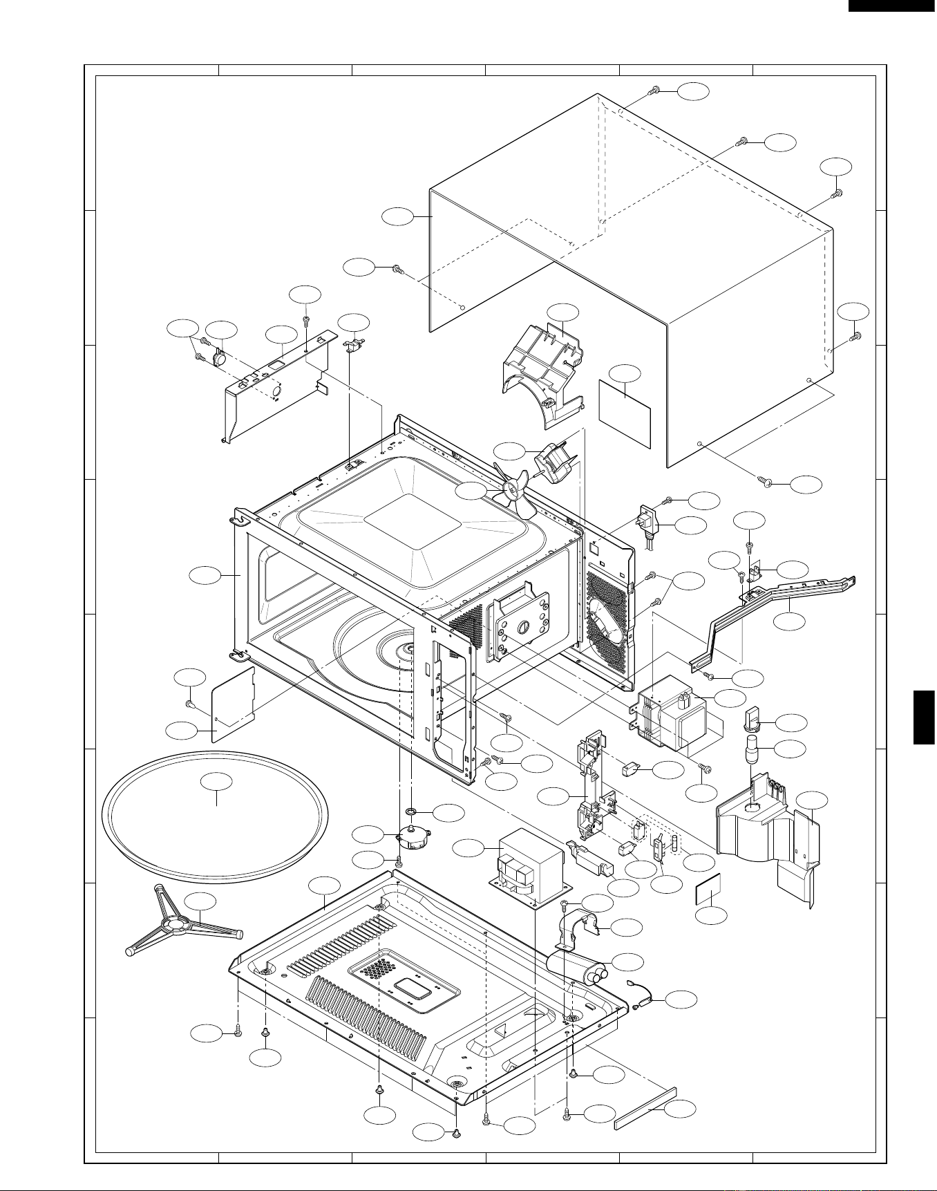
43
R-519CK
R-530CK
R-530CW
6
45
1
2
3
6
45
1
2
3
A
B
C
D
E
F
G
H
A
B
C
D
E
F
G
H
OVEN AND CABINET PARTS
4-9
6-10
2-3
4-7
6-7
1-5
4-6
4-8
6-5
6-4
2-1
7-6
1-12
4-10
7-2
7-2
7-5
4-3
1-13
1-10
4-11
1-15
7-2
7-11
7-3
7-6
1-9
7-8
7-8
4-2
7-5
1-11
1-3
1-4
7-4
1-8
1-8
4-4
7-1
4-1
1-1
1-2
2-2
2-2
2-2
2-2
7-5
7-5
4-12
7-5
6-6
1-7
1-6
4-5
1-14
7-7
7-7
7-10
7-9
7-9
7-10
Downloaded from www.ManualsFile.com manuals search engine
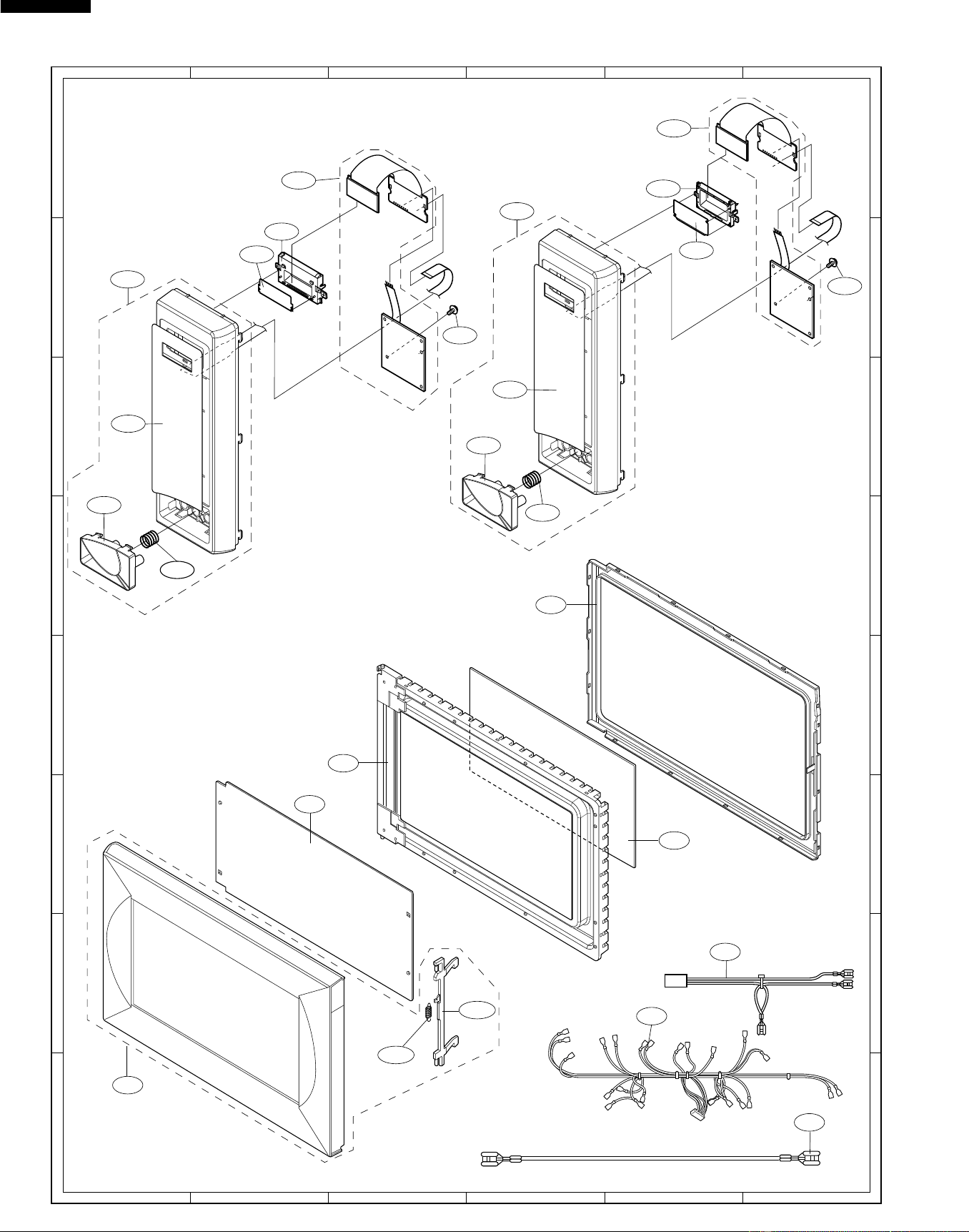
44
R-519CK
R-530CK
R-530CW
6
45
1
2
3
6
45
1
2
3
A
B
C
D
E
F
G
H
A
B
C
D
E
F
G
H
CONTROL PANEL PARTS
MISCELLANEOUS
Actual wire harness may be different from illustration.
6-3
6-2
6-1
5-1
5-1-2
5-1-1
5-3
5-4
5-5
5-2
R-519CK
R-530CK/CW
3-3
3-1
3-4
3-2
3-2-2
3-2-3
3-5
3-2-1
3-1
3-3
3-4
3-2-1
3-2-2
3-2-3
3-5
3-2
DOOR PARTS
Downloaded from www.ManualsFile.com manuals search engine
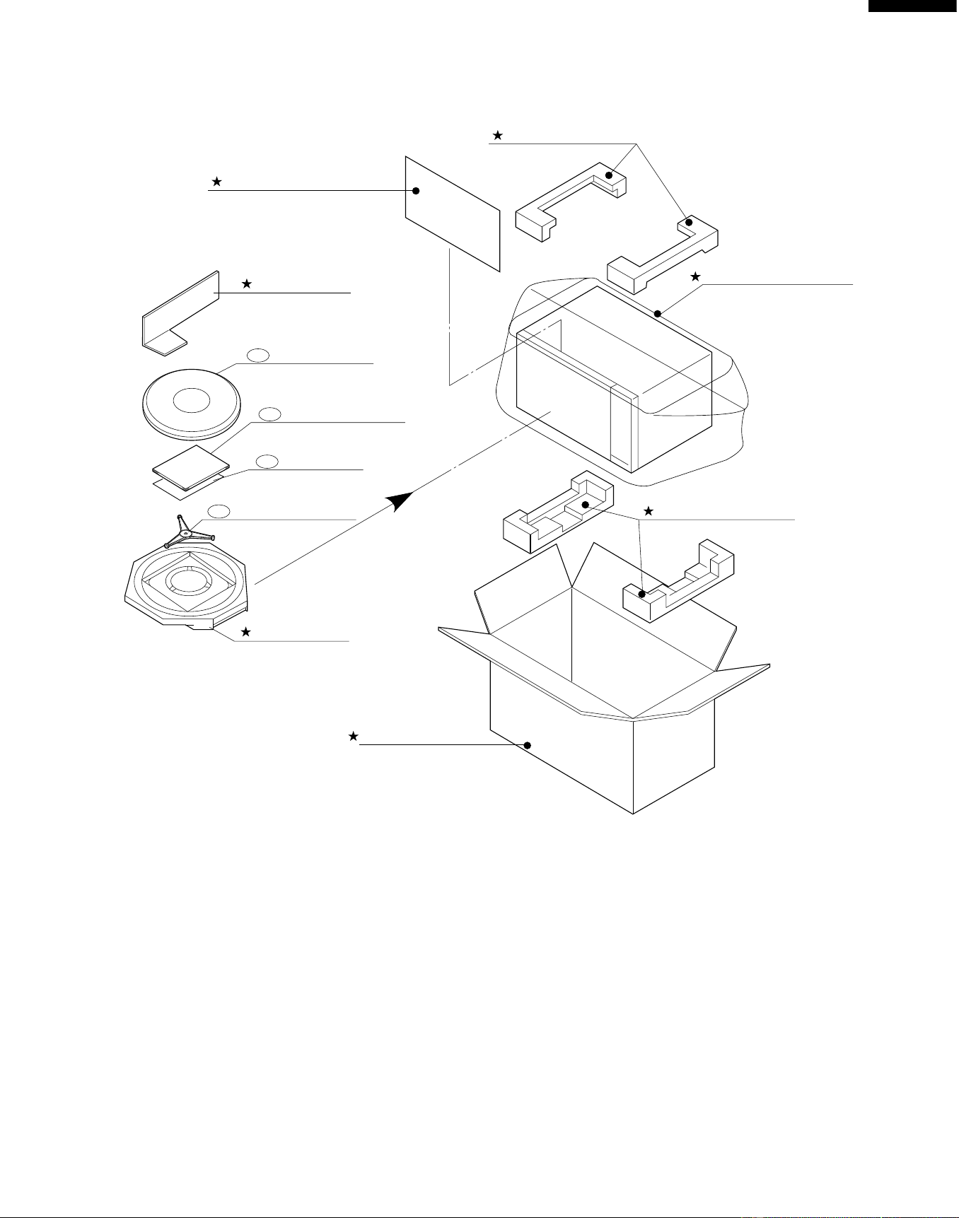
45
R-519CK
R-530CK
R-530CW
PACKING AND ACCESSORIES
DOOR PROTECTION SHEET
SPADP0221MRE0
PLASTIC BAG
SSAKHA009WRE0 (R-519CK)
SSAKHA009WRE0 (R-530CK)
SSAKHB005MRE0 (R-530CW)
PACKING CASE
SPAKCB258MRR6 (R-519CK)
SPAKCB258MRR4 (R-530CK)
SPAKCB258MRR5 (R-530CW)
TOP PAD ASSEMBLY
FPADBB038MRE0
INTO THE OVEN CAVITY
6-5 TURNTABLE TRAY
6-4 TURNTABLE SUPPORT
6-8 OPERATION MANUAL
6-9 RECIPE CARD
TRAY PACK
SPADPB038MRE0
BOTTOM PAD ASSEMBLY
FPADBB039MRE0
TRAY HOLDER
SPADFB015MRE0
Downloaded from www.ManualsFile.com manuals search engine

46
R-519CK
R-530CK
R-530CW
'99 SHARP CORP. (2S2.530E) Printed in U.S.A
COPYRIGHT © 1999 BY SHARP CORPORATION
ALL RIGHTS RESERVED.
No part of this publication may be repro-
duced, stored in retrieval systems, or trans-
mitted in any form or by any means, elec-
tronic, mechanical, photocopying, record-
ing, or otherwise, without prior written per-
mission of the publisher.
Downloaded from www.ManualsFile.com manuals search engine