INSTALLATION AND USER’S GUIDE
SKU: 75409
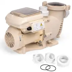
VARIABLE SPEED PUMP
2.2HP 230V 2 INCH
75409
Read all safety warnings and instructions. Failure to follow the
warnings and instructions may result in serious injury. Save all
warnings and instructions for future reference.
DANGER

THIS PAGE INTENTIONALLY LEFT BLANK

TABLE OF CONTENTS
1
TABLE OF CONTENTS
IMPORTANT SAFETY INSTRUCTIONS
OVERVIEW (PRODUCT INFORMATION)
SPECIFICATION
INSTALLATION
LOCATION
PIPING
ELECTRICAL INSTALLATION
INITIAL SETUP
Legends and Symbols
1
2
2
4
5
6
6
7
PRODUCT INTRODUCTION
4
KEYPAD FUNCTIONS
INITIAL PROGRAMMING
SETTING THE CLOCK
11
12
12
USING THE DEFAULT SCHEDULE
12
8
10
CUSTOM SCHEDULE PROGRAMMING
OPERATING THE PUMP IN ACTIVE MODE
PROGRAMMING QUICK CLEAN
13
15
16
DIMENSIONS
5
MAINTENANCE
CLEANING THE PUMP STRAINER BASKET
MOTOR CARE
TROUBLESHOOTING 25
Disclaimer
DISCLAIMER 29
29
Customer Service and Technical Support
29
20
PUMP DISASSEMBLY AND REASSEMBLY
PUMP RESTARTING
WINTERIZING
22
23
24
20
21
OPERATION
10
FACTORY RESET
PRIMING
17
18
REPLACEMENT PARTS 28
IMPORTANT SAFETY INSTRUCTIONS
2
For safety reasons, children should not be allowed to use this product.
Packing materials and plastic bags are not toys. Keep them away from children to prevent the risk
of suffocation.
Failure to comply with all instructions and warnings may lead to severe bodily
injury or even death. For optimal safety and functionality, it is advisable to have the product installed
and serviced by a certified service professional. Prior to using this product, installers, operators, and
owners must carefully review these warnings and all instructions provided in the owner's manual. It
is essential to leave these warnings and the owner's manual with the owner for their reference and
safety.
ATTENTION INSTALLER: This manual contains vital information regarding the installation,
operation, and safe use of this product. It is essential to provide this manual to the end user of the
product. Failure to read and follow all instructions could lead to severe injuries.
USE OF NON-XTREMEPOWERUS REPLACEMENT PARTS VOIDS WARRANTY
DANGER: Ignoring these hazards can result in death, severe personal injury, or
significant property damage.
WARNING: Indicates potential hazards that can result in severe personal injury,
death, or significant property damage. Ignoring these warnings presents a real
danger.
CAUTION: Indicates potential hazards that can result in minor or moderate
personal injury, property damage, or actions that are unpredictable and unsafe.
Ignoring these cautions presents a potential hazard.
NOTICE: This label indicates important special instructions that are not directly
related to hazards.
This guide provides instructions for installing and using the VARIABLE SPEED PUMP. If you have
any questions about the equipment, please contact XtremepowerUS.
This guide contains important information about safely installing and operating this product. After
installation, make sure to share this information with the owner/operator or leave it with them for
their reference.
Legends and Symbols
When you come across the safety-alert symbol on your equipment or in this manual, pay attention
to the following signal words and remain vigilant about the potential for personal injury.
IMPORTANT SAFETY INSTRUCTIONS
DANGER
WARNING
WARNING
CAUTION
NOTE
DANGER
IMPORTANT SAFETY INSTRUCTIONS
3
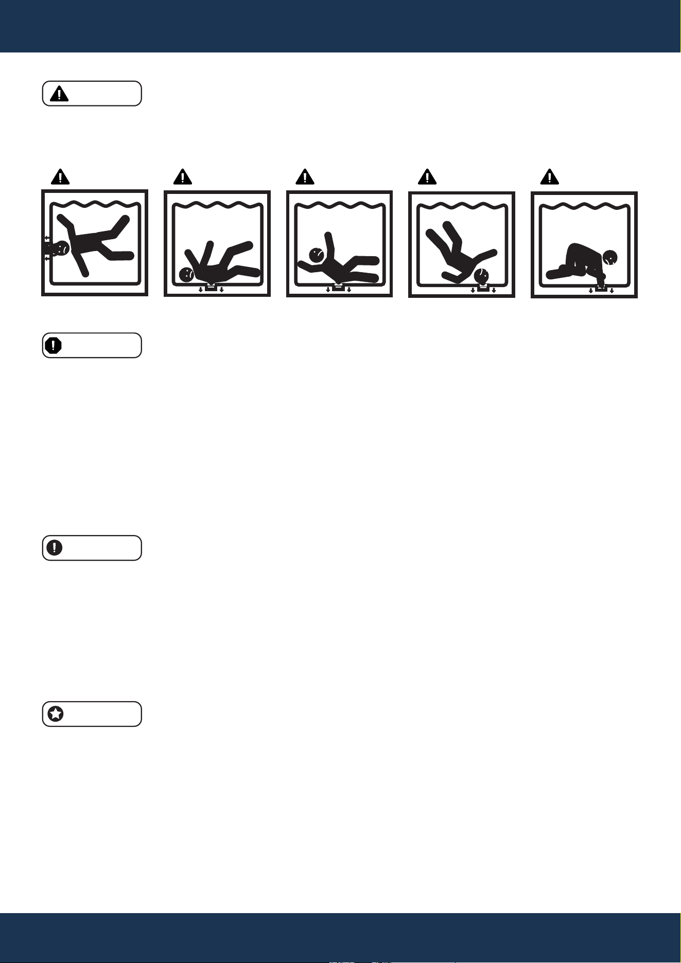
• Suction Entrapment Risk: High suction can trap and drown individuals near drains or broken
covers. Avoid using the pool or spa if drain covers are missing, cracked, or damaged.
• Electrical Hazard: Never open the pump's drive or motor enclosure to avoid electrical hazards.
DANGER
WARNING
CAUTION
• System Sizing and Installation: Ensure that pumps are properly sized and installed to avoid
injury, system damage, or compromised performance.
• Suction entrapment hazard: Stay off the main drain and away from suction outlets.
• Anti-Entrapment Covers: Ensure properly installed and secured anti-entrapment covers are in
place to prevent hazards. Maintain distance from main drains and suction outlets. If possible,
disable suction outlets or convert them to return inlets.
• Code Compliance: All suction plumbing installations must comply with national and local
codes.
NOTE
• Intended Use: This pump is for permanent swimming pools and compatible hot tubs or spas. It
is not for use with storable pools.
• Manual and Label Adherence: Review the product manual for important operation and
maintenance guidelines.
• Safe Electrical Setup: Electrical installations must allow for safe operation without exposing
users to electrical risks.
• Safety Labels: Maintain safety labels in good condition for clear visibility of hazards and
replaced if damaged.
• Air Relief: Before starting the system, open the air relief valve and confirm all system valves are
open to avoid pressure buildup.
• Qualified Installation: Pool pump installation and servicing should only be performed by a qual-
ified pool service professional.
• Correct Application: Avoid using the pump in settings for which it was not designed, as improp-
er usage can lead to injury or death.
• Adult Supervision: This product is not suitable for use by children without adult supervision.
• Ensure Safe Operation: Only install the pump in applications that match its intended design.
• High-Pressure Hazard: Pool circulation systems operate under high pressure, which can lead
to serious injury if improperly handled.
• Start-Up Precautions: Stand clear of the system during start-up to avoid potential hazards from
pressure surges.
SUCTION ENTRAPMENT HAZARD
DANGER DANGER DANGER DANGER DANGER

OVERVIEW (PRODUCT INFORMATION)
4
OVERVIEW (PRODUCT INFORMATION)
PRODUCT INTRODUCTION
This pump boasts a variable frequency drive that ensures premium efficiency, allowing for flexible
adjustments in motor speed and operation duration. Capable of functioning across a broad speed
spectrum of 1000 to 3450 RPM, it is also designed to work with 230 VRMS nominal voltage at both
50HZ and 60HZ frequencies. Engineered to prioritize energy conservation, the pump maintains
cleanliness at the lowest necessary speeds, with optimal settings being influenced by pool
dimensions, additional water features, sanitation chemicals used, and environmental conditions.
Determining the most energy-efficient settings may require a period of trial and optimization.
DRIVE
• User-friendly interface
• Weather-resistant design
• Integrated daily timer
• Adjustable start-up priming
• Programmable Quick Clean function
• Persistent alarm system
• 230V input, compatible with 50/60Hz
• Overload protection circuit
• Clock memory during power cuts
PUMP
• Ultra-quiet operation
• 2-inch connections for straightforward replacement
• Transparent lid for strainer basket monitoring
• Self-priming for fast startup
MOTOR
• High-efficiency, permanent magnet design
• 56 square flange size
• Quiet performance
• Outdoor-rated durability
• Cooler operation through high efficiency
• Surpasses Department of Energy and Energy Star standards
• TEFC (totally enclosed fan-cooled) motor with permanent magnets
OVERVIEW (PRODUCT INFORMATION)
5
SPECIFICATION
SKU
Power
Connection
Electrical Requirements
Maximum Power Consumption
Maximum Shaft Horsepower
Maximum Current
Maximum Flow Rate Per Minute
Maximum Head Lift
Speed Range
Hydraulic Horsepower (HHP)
Total Horsepower (THP)
Protection Rating
Storage Temperature Range
Operating Temperature Range
Humidity Tolerance
75409
2.2 HP
2” Inlet/Outlet
230V, 50/60HZ
1800 W
2.2 HP
7.8 AMPS
131 GPM (Gallons Per Minute)
81.4 FT
1000 ~ 3450 RPM (Revolutions Per Minute)
1.138
2.20
IPX 5 (Water Resistant)
-40°F ~ 140°F
32°F ~ 122°F
0% ~ 95% Relative Humidity, Non-Condensing
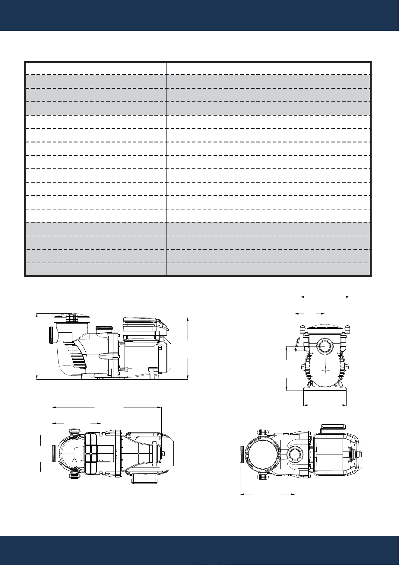
DIMENSIONS
13.7”
347mm
12.9”
328mm
9.1”
232mm
8.9”
225mm
10.3”
262mm
11.3”
288mm
10.2”
258mm
22.6”
574mm
7.6”
194mm
6.3”
159mm
INSTALLATION
6
INSTALLATION
LOCATION
• Installation should be performed only by a qualified plumbing professional to ensure proper
setup and to mitigate safety risks.
• Refer to the IMPORTANT SAFETY INSTRUCTIONS on pages i–ii and 2–3 for detailed safety
and installation guidance.
NOTE
• Do not install the pump in an enclosed space, such as an external enclosure or under a hot tub
or spa skirt.
• Ensure that the pump is securely attached to a stable equipment pad for optimal performance.
LOCATION REQUIREMENTS
• Place the pump close to the pool or spa, using short, direct piping for both suction and return
lines to reduce friction loss and increase efficiency.
• Maintain a minimum distance of 5 feet from the pool or spa's inner wall (9.8 feet in Canada).
• Keep the pump at least 3 feet away from the heater outlet.
• Avoid placing the pump more than 5 feet above the water level to prevent operational issues.
• Install the pump in a well-ventilated area, away from moisture sources such as rain gutters and
sprinklers.
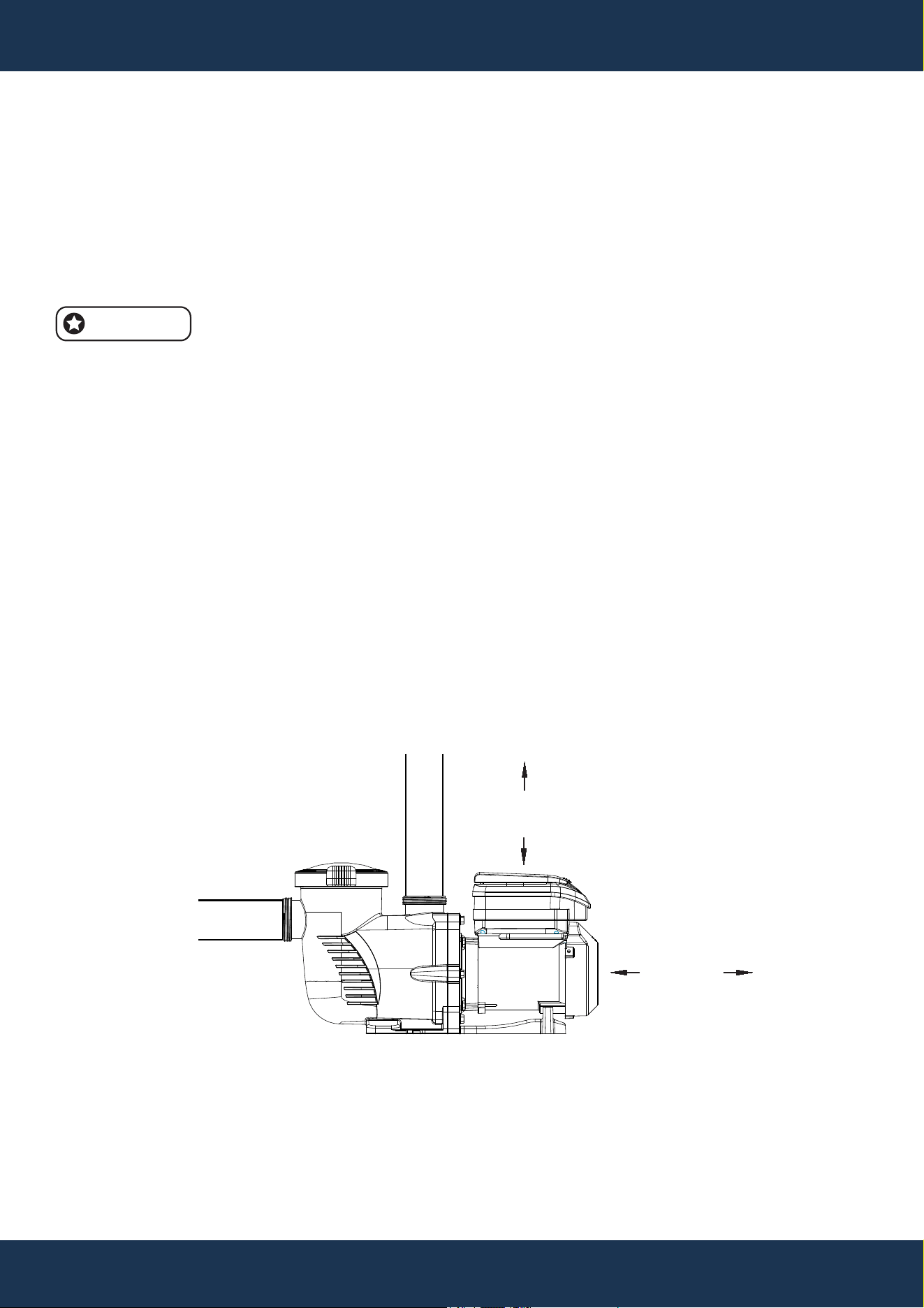
• Leave at least 3 inches of clearance at the rear for motor removal and 5 inches on top for
keypad accessibility (see Figure 1).
FIGURE 1
3”
MINIMUM
5”
MINIMUM
PIPING
INSTALLATION
7
PIPING GUIDELINES
• Use larger piping to increase plumbing efficiency, ensuring that the suction side pipe diameter
is equal to or larger than that of the return line to facilitate optimal flow.
• Ensure that the suction side pipe diameter is equal to or larger than the return line to facilitate
optimal flow.
• Keep the suction side piping as short as possible to enhance pump performance.
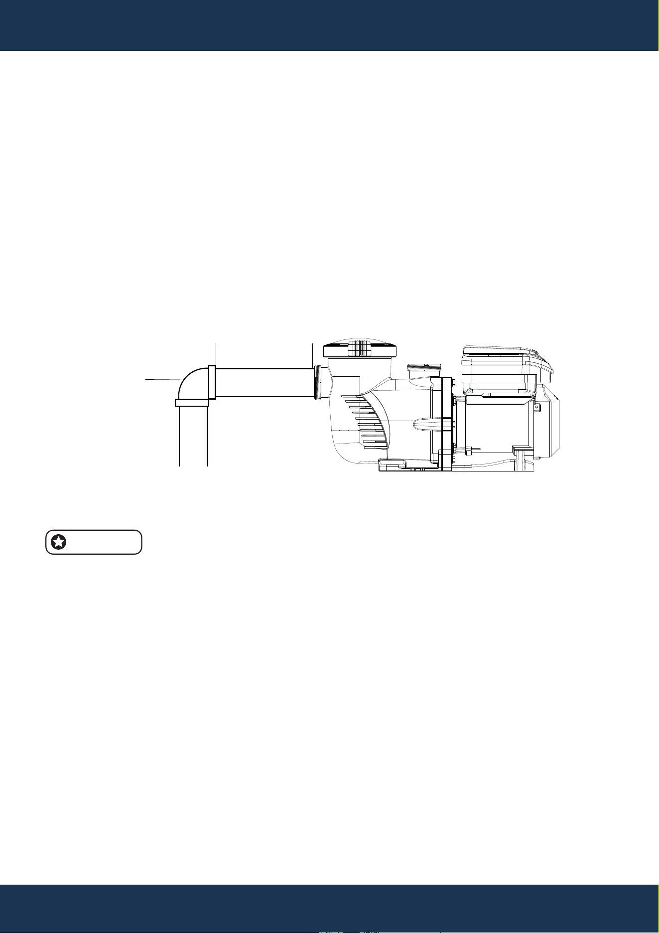
• Maintain a straight section of pipe on the suction line that is at least five times the pipe’s
diameter before the pump’s inlet. Refer Figure 2.
• Example: For a 2.5-inch diameter pipe, ensure at least 12.5 inches of straight piping before the
suction port. This setup improves priming speed and extends the lifespan of the pump by
reducing turbulence.
FIGURE 2
5 TIMES SUCTION
PIPE DIAMETER.
ELBOW
FITTINGS AND VALVES
FITTINGS AND VALVES GUIDELINES
• For flooded suction systems, install gate valves on both the suction and discharge pipes to allow
for easy isolation during maintenance.
• Position the suction gate valve at least five times the suction pipe’s diameter away from the
pump to prevent interference with flow dynamics.
• Install a check valve on the discharge line, especially if the plumbing has a significant rise after
the pump, to prevent water backflow and help maintain consistent pump performance.
• When plumbing two pumps in parallel, install check valves on each pump’s discharge line to
prevent reverse rotation of the impeller and motor, which can occur if one pump is running while
the other is off or during fluctuations in flow.
NOTE
• To reduce turbulence and prevent cavitation, avoid placing 90° elbows directly at the pump’s
suction port (see Figure 2).

8
ELECTRICAL INSTALLATION
INSTALLATION
WIRING INSTRUCTIONS
• Turn off all breakers and switches before beginning motor wiring.
• Verify that the supply voltage matches the motor's nameplate specifications.
• Adhere to the National Electrical Code and local codes for wire sizes and requirements; select
a heavier gauge wire if uncertain.
• Ensure all electrical connections are secure and free of corrosion. Trim wires to fit terminals
precisely, avoiding excess overlap or contact. Trim wiring to fit terminals without excess overlap
or contact.
• Always replace the drive lid after completing wiring or when leaving the pump unattended to
protect it from the elements.
WARNING
• Risk of Electrical Shock or Electrocution: It is strongly recommended that a certified electrician
or qualified professional install this pump in accordance with the National Electrical Code and
local regulations to mitigate the risk of serious injury, death, or property damage.
• Always disconnect power at the circuit breaker before servicing to prevent electric shock or
injury.
• Read all instructions carefully before servicing the pump.
NOTE
• The pump is designed to operate with a 230 V single-phase input, compatible with both 50 and
60 Hz. Its power connections support up to 8 AWG solid or stranded wire.
NOTE
• Take care not to pinch wires when securing the drive body and lid.
GROUNDING INSTRUCTIONS
• Ensure the motor is permanently grounded using the Grounding Terminal located in the drive's
wiring compartment. Comply with the National Electrical Code and local regulations regarding
the grounding wire's size and type."
• Attach the ground wire to the electrical service’s ground.

INSTALLATION
9
BONDING INSTRUCTIONS
• Connect the motor to the pool's structural metal components, electrical systems, and metal
conduits and piping within 5 feet of the pool or spa’s inner walls using the provided bonding lug
on the motor’s side. Comply with the current National Electrical Code and local codes for
bonding practices.
• A solid copper conductor of at least 8 AWG is required for bonding. For installations in Canada,
a 6 AWG or thicker solid copper conductor is necessary.
L1/L
L2/N
GND
FIGURE 3

10
OPERATION
OPERATION
INITIAL SETUP
• Before initial use of the pump, program its internal clock and operational schedules. Instructions
for setting the clock are available under SETTING THE CLOCK and USING THE DEFAULT
SCHEDULE. For custom schedule programming, see CUSTOM SCHEDULE PROGRAMMING.
• The drive keypad allows programming and control of the pump and provides access to all
features and settings.
WARNING
CAUTION
NOTE
• The pump’s functionality may vary if features like External Control Only Mode or Keypad Lockout
are enabled.
• Close the keypad cover after each use to protect the keypad and drive components from
potential damage.
• To avoid damaging the keypad, use only your fingers to press the buttons; do not use
screwdrivers, pens, or other tools for programming the pump.
• If the pump motor is connected to power, pressing any buttons mentioned in this section may
activate the motor. Unexpected motor start-ups could result in personal injury or equipment
damage. Always be aware of the motor’s power status when programming or servicing.

1 2 3 4
Speed
Watts
Time
Duration
AM
PM
Display
Setting
Enter
Start
Stop
Quick
Clean
+
-
>
<
8
4
3
5
6
1
2
9
7
11
OPERATION
KEYPAD FUNCTIONS
10
11
12
FIGURE 4
SPEED 1
SPEED 2
SPEED 3
SPEED 4
QUICK CLEAN KEY
START / STOP KEY
MAIN MENU ACCESS
DISPLAY BUTTON
ARROW KEYS
UP KEY
DOWN KEY
LEFT KEY
CONTROL PANEL DIGITAL DISPLAY
DISPLAY MODE LED INDICATOR
POWER LED INDICATOR
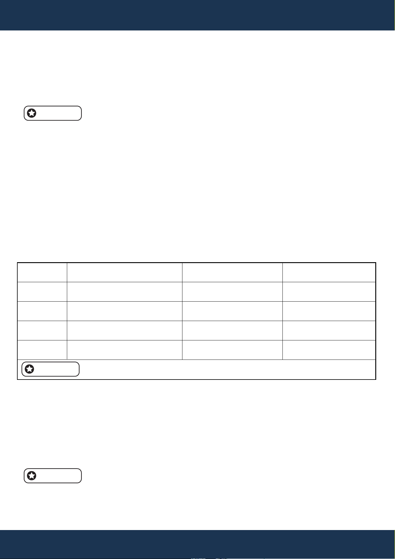
Press to activate Speed 1 (2850 RPM).
The corresponding LED will illuminate to confirm that Speed 1 is active.
Press to select Speed 2 (1730 RPM).
An illuminated LED indicates that Speed 2 is active.
Press to select Speed 3 (2300 RPM).
The LED light confirms that Speed 3 is active.
Press to select Speed 4 (1150 RPM).
An illuminated LED indicates that Speed 4 is active.
Dedicated button for Quick Clean function.
Press to start or stop the pump. A lit indicator signifies that the pump
is operational or in a specific. A blinking indicator light shows that the
pump is off and awaiting the next scheduled mode.
Press to enter the main menu directory when the frequency converter
is powered down.
Press to switch between different display contents during pump operation.
Press to increase speed or time during adjustments.
Press to decrease speed or time during adjustments.
Press to move the cursor to the left.
The display screen shows various operational parameters,
such as current speed, time, duration, power consumption,
Bluetooth connectivity status, and more.
Works in conjunction with the display button. The LED
lights up to match the information shown on the digital
display. A blinking LED indicates that the current
parameter can be edited.
An illuminated LED indicates that the pump is powered
and receiving energy
1
2
3
4
5
6
7
8
9
10
11
12
12
OPERATION
INITIAL PROGRAMMING
• Before first use, set the pump’s internal clock and operational schedules as detailed in this
manual. Refer to Setting the Clock in this section and CUSTOM SCHEDULE PROGRAMMING
for step-by-step instructions.
NOTE
• When setting up a new schedule, ensure that the start times for Speeds 1 through 4 are
programmed in chronological order within a 24-hour period.
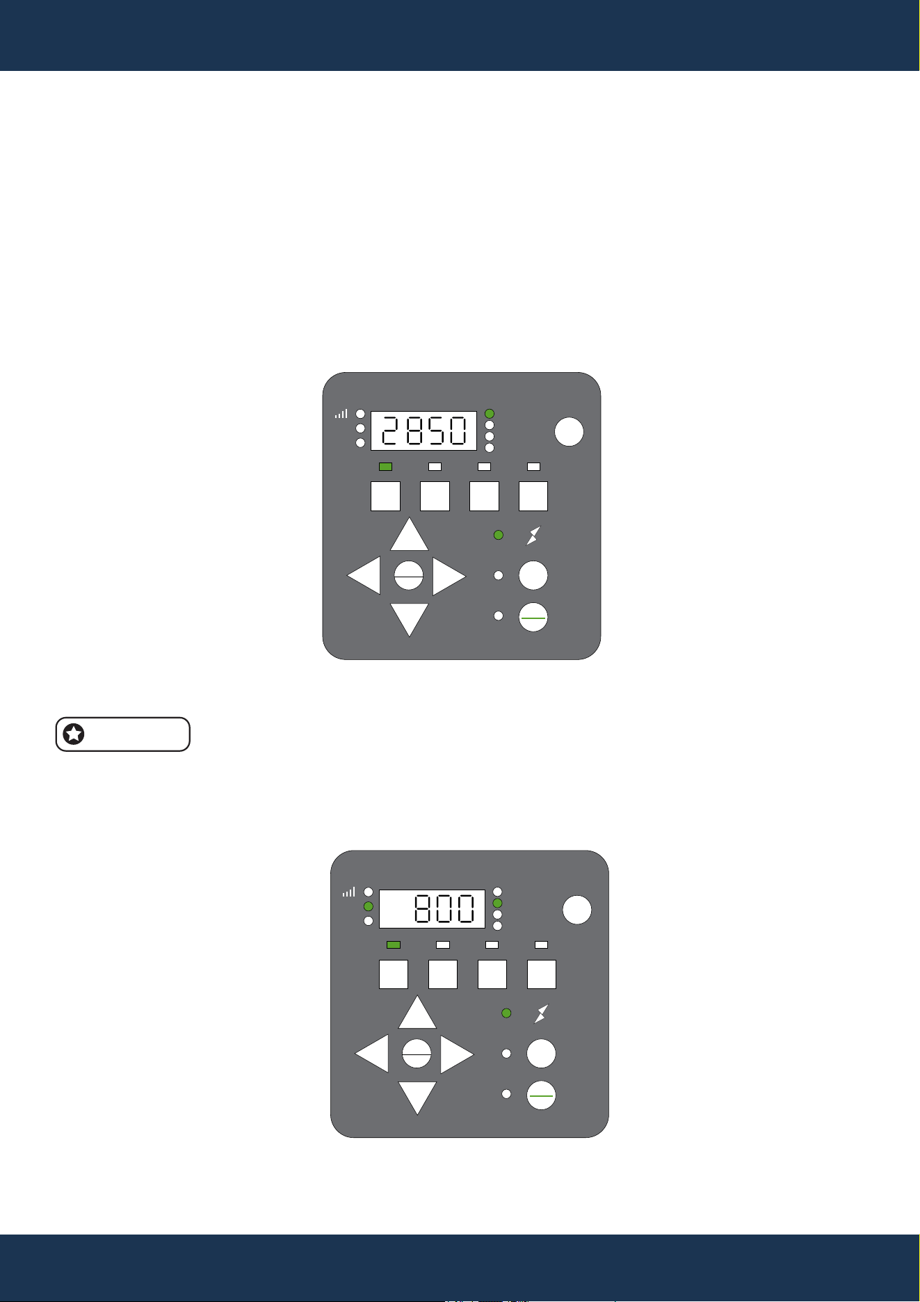
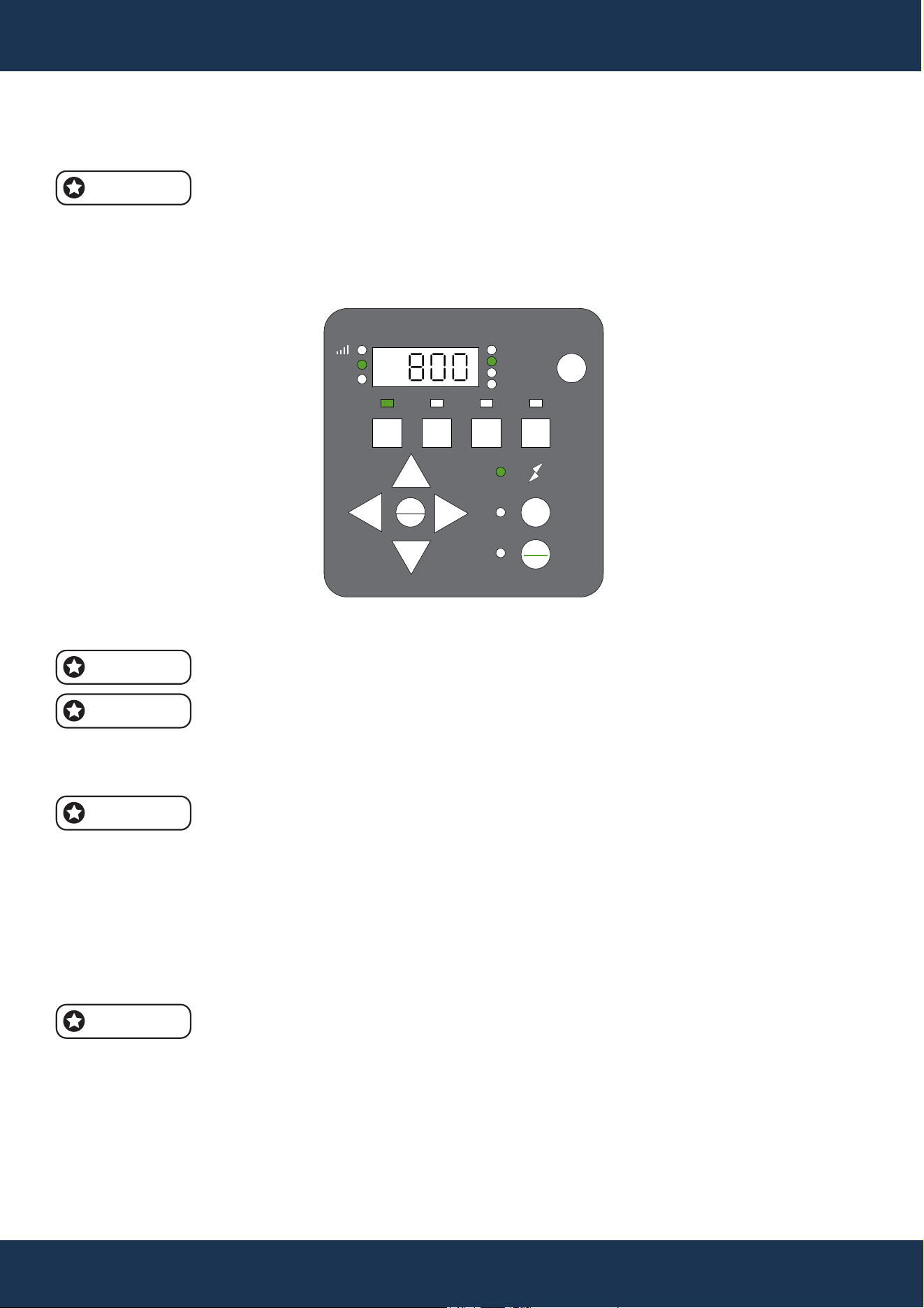
SETTING THE CLOCK
• When the pump is first connected to power, the clock will flash, indicating the need for setup.
• Press Setting. Use the + and - buttons to set the current time, < and > to adjust the cursor
position. In 12-hour format, AM/PM will be displayed.
• In 12-hour format, AM/PM will be displayed.
USING THE DEFAULT SCHEDULE
• The default schedule provides adequate daily circulation for most pools (see Table 2 for details).
DEFAULT SCHEDULE OPERATES
• SPEED 1: Starts at 8:00 AM, runs at 2850 RPM for 2 hours.
• SPEED 2: Starts at 10:00 AM, runs at 1730 RPM for 10 hours.
• SPEED 3: Starts at 8:00 PM, runs at 2300 RPM for 2 hours.
• SPEED 4: Starts at 10:00 PM, runs at 1150 RPM for 8 hours.
• Following SPEED 4, the pump pauses for 2 hours and then resumes with SPEED 1. This cycle
repeats, maintaining a 22-hour daily operation as set by the factory until altered by the user.
To start the pump, press the Start/Stop button and ensure that the corresponding
LED is illuminated.
PROGRAM
SPEED 1
SPEED 2
SPEED 3
SPEED 4
STARTUP TIME
8:00AM (8:00)
ADJUSTABLE)
10:00AM (10:00) (ADJUSTABLE)
8:00AM (20:00) (ADJUSTABLE)
10:00AM (22:00) (ADJUSTABLE)
OPERATION DURATION
2 HRS
(ADJUSTABLE)
10 HRS (ADJUSTABLE)
2 HRS (ADJUSTABLE)
8 HRS (ADJUSTABLE)
DEFAULT SPEED
2850 RPM
(ADJUSTABLE)
1730 RPM (ADJUSTABLE)
2300 RPM (ADJUSTABLE)
1150 RPM (ADJUSTABLE)
THE DEFAULT OPERATING CYCLE OF THE PUMP IS SET TO RUN FOR 22 HOURS PER DAY.
NOTE
NOTE
13
OPERATION
CUSTOM SCHEDULE PROGRAMMING
• Ensure the pump is halted, with the Start/Stop LED off, before customizing your sch A blinking
LED next to the parameter being edited indicates that it is in programming mode.
TO SET A CUSTOM SCHEDULE
1. Press Start/Stop to stop the pump.
2. Then, press '1' to edit Speed 1; its LED and 'Speed' will blink (see Figure 5).
FIGURE 5
1 2 3 4
Speed
Watts
Time
Duration
AM
PM
Display
Setting
Enter
Start
Stop
Quick
Clean
+
-
>
<
Adjust the Speed 1 RPM using the + and - buttons, and move the cursor with the < and > buttons.
Speed adjusts in 100/10/1 RPM increments.
4. Press '1' to set the start time for Speed 1; 'Time' will blink (see Figure 6).
FIGURE 6
1 2 3 4
Speed
Watts
Time
Duration
AM
PM
Display
Setting
Enter
Start
Stop
Quick
Clean
+
-
>
<
NOTE
5. Set the start time with the + and - buttons, adjusting the cursor with < and >.
Adjust speed in increments of 100/10/1 RPM, and adjust time in increments of 1
hour/10 minutes/1 minute.
6. Press '1' to set the duration for Speed 1; 'Duration' will blink (see Figure 7).
FIGURE 7
14
OPERATION
TO SET A CUSTOM SCHEDULE (CONTINUED)
1 2 3 4
Speed
Watts
Time
Duration
AM
PM
Display
Setting
Enter
Start
Stop
Quick
Clean
+
-
>
<
7. Set the duration using the + and - buttons, and adjust the cursor with < and >.
Duration adjusts in increments of 1 hour and 10 minutes.
If set to 0, the pump will skip this segment.
8. Confirm the Speed 1 setup. Subsequent presses of '1' will cycle through the settings, saving
changes instantly.
Pressing 1 cycles through SPEED 1 settings; changes save automatically.
9. To set Speed 2, press '2' and follow the same steps as for Speed 1.
10. Adjust the Speed 2 RPM using the +, -, <, and > buttons.
11. To display the Speed 2 setup, press '2'.
12. Set the Speed 2 duration using the +, -, <, and > buttons.
13. Follow steps 9–12 to set Speed 3, Speed 4, and Quick Clean settings.
14. To activate the pump with the new schedule, press Start/Stop; the LED will light up.
If the pump was manually stopped, press Start/Stop again to start the schedule.
A lit Start/Stop LED indicates that the pump will follow the set schedule.
NOTE
NOTE
NOTE
NOTE
NOTE

15
OPERATION
SPEED PRIORITIZATION FOR SCHEDULING (WITHOUT EXTERNAL CONTROL)
• When the pump operates based on its internal schedule, the programmed speeds follow a
priority sequence from highest to lowest: SPEED 1 has the highest priority, followed by SPEED
2, SPEED 3, and finally, SPEED 4 with the lowest priority.
• The prioritization order is detailed in an accompanying table for reference.
Example:
STARTING SCHEDULE (BEFORE ADJUSTMENT)
• SPEED 1: Start time = 8:00 AM; Duration = 6 hours
• SPEED 2: Start time = 9:00 AM; Duration = 1 hour
• SPEED 3: Start time = 10:00 AM; Duration = 1 hour
• SPEED 4: Start time = 2:00 PM; Duration = 1 hour
According to this priority, the pump will run in SPEED 1 mode from 8:00 AM
to 2:00 PM, skipping SPEED 2 and SPEED 3, as their time frames fall within
the SPEED 1 period. The pump will then run in SPEED 4 mode from 2:00 PM
to 3:00 PM
End Schedule (After Adjustment)
• SPEED 1: Start time = 8:00 AM; Duration = 6 hours
• SPEED 4: Start time = 2:00 PM; Duration = 1 hour
OPERATING THE PUMP IN ACTIVE MODE
CAUTION
• When the pump is powered, pressing any button described in this section may activate the
motor, potentially causing personal injury or equipment damage.
OPERATING THE PUMP IN ACTIVE MODE
• The Display button toggles through active settings including SPEED (current RPM), TIME
(current time), DURATION (time left at current speed), and WATTS (current power usage).
• Pressing any Speed button (1, 2, 3, 4, or Quick Clean) during operation temporarily overrides
the current setting. The pump will run at the selected speed for the preset duration, then resume
the regular schedule.
NOTE
• Changes to schedule speeds during operation apply only for the remaining duration of the active
program and will not permanently save these adjustments.
16
OPERATION
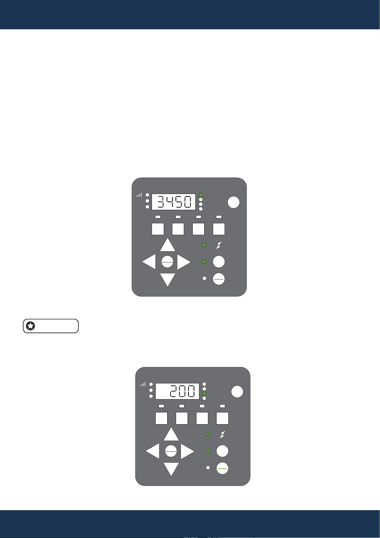
PROGRAMMING QUICK CLEAN
QUICK CLEAN FEATURE SETUP
• The pump includes a Quick Clean option, which allows temporary operation at speeds ranging
from 1700 to 3450 RPM. After a Quick Clean cycle, the pump reverts to its scheduled program.
• The drive's prioritization is outlined in an accompanying table for reference.
PROGRAMMING QUICK CLEAN
• Stop the pump by pressing Start/Stop, then activate Quick Clean mode; the Quick Clean and
'Speed' LEDs will flash (see FIGURE 8).
• Set the RPM using the + and - keys, and navigate with < and >.
RPM can be adjusted in increments of 100, 10, or 1 RPM.
• Press Quick Clean again to set the duration; the 'Duration' LED will blink (see FIGURE 9).
NOTE
FIGURE 8
1 2 3 4
Speed
Watts
Time
Duration
AM
PM
Display
Setting
Enter
Start
Stop
Quick
Clean
+
-
>
<
FIGURE 9
1 2 3 4
Speed
Watts
Time
Duration
AM
PM
Display
Setting
Enter
Start
Stop
Quick
Clean
+
-
>
<

17
OPERATION
PROGRAMMING QUICK CLEAN (CONTINUED)
• Adjust the duration in hours and minutes using + and - keys, and navigate with < and >.
Duration adjustments are available in increments of 1 hour or 10 minutes, with a
range from 10 minutes to 24 hours.
The Quick Clean duration setting will not affect the programmed start time of the
regular schedule.
NOTE
NOTE
FACTORY RESET
To revert the drive to its default settings, perform a Factory Reset. This action will erase all
customized settings and schedules except for the current time of day. Confirm the necessity of this
action before proceeding, as the reset takes immediate effect.
FACTORY RESET PROCESS
• Stop the pump by pressing the Start/Stop button if it is currently running.
• Hold down the “1” and “2” buttons simultaneously for 3 seconds.
• A prompt tone lasting 3 seconds will confirm a successful reset
After the reset, reprogram the schedule and priming speed as outlined in previous sections. To
activate the pump for subsequent operation, press the Start/Stop button; the pump will then follow
the newly set schedule."
18
OPERATION
PRIMING
STARTUP AND PRIMING PROCESS
• At startup, the pump automatically begins a priming cycle, separate from any Quick Clean cycle.
It starts at 2400 RPM and gradually increases to 3200 RPM over 5 minutes, with the drive
displaying the time remaining.
CAUTION
• The pump is pre-set to Priming mode, which causes it to automatically accelerate to 3200 RPM
upon initial start-up.
• Before activating the pump:
◦ Open the filter’s air relief valve.
◦ Ensure that all necessary valves are open.
◦ Confirm that the return line is unobstructed.
◦ Fill the pump with water.
◦ Maintain a safe distance from the filter and any pressurized vessels.
WARNING
• Never run the pump dry, as it will damage the shaft seal and cause leaks.
• Replace any damaged seal immediately to prevent leaks.
• Maintain the proper water level in your pool (at least halfway up the skimmer opening) to prevent
air from being drawn through the skimmer.
• A low water level can cause the pump to lose its prime, potentially leading to seal damage.
• Continuous operation with a compromised seal can damage the pump body and impeller, and
may lead to personal injury and property damage.
NOTE
• If the control system’s priming timer is still running after the priming cycle, the pump will continue
at the control system’s set speed until the timer expires.
• The startup speed can be adjusted between 3200 RPM and 3450 RPM using the '+' and '-'
buttons during boot-up.
NOTE
• The initial boot begins with a 5-minute countdown. Press any Speed button (1 to 4) to exit the
priming mode prematurely.
• Upon subsequent startups, the pump will assess the need for priming, taking approximately 20
seconds to determine if priming is required.

19
STARTUP AND PRIMING PROCESS (CONTINUED)
• Priming duration may vary with local conditions, such as water temperature, atmospheric
pressure, and pool water level, which should all be considered when selecting the priming
speed. Test and adjust priming speeds as needed, allowing the system to drain between tests.
NOTE
• To avoid air intake into the system, ensure the pump strainer pot is filled with water up to the
bottom of the suction port.
OPERATION

20
MAINTENANCE
CAUTION
STRAINER POT HANDLING
• Never open the strainer pot if the pump has failed to prime or has operated without water, as
vapor pressure build-up may cause scalding water inside.
• Opening under these conditions can lead to severe injury.
• Ensure both suction and discharge valves are open, and verify that the strainer pot is cool
before cautiously opening it.
POWER DISCONNECTION
• Always turn off power at the circuit breaker and disconnect the digital input cable before
servicing the pump. Failing to do so may result in fatal or severe electric shock injuries.
• Neglecting this step can cause fatal or severe electric shock injuries. Read and understand all
service instructions prior to performing pump maintenance.
PUMP MAINTENANCE
• To prevent pump damage and maintain system efficiency, regularly clean the pump strainer and
skimmer baskets.
MAINTENANCE
WARNING
CLEANING THE PUMP STRAINER BASKET
The strainer pot, located at the front of the pump, contains the strainer basket. Inspect the basket
through the pot lid visually at least once a week. Regular cleaning ensures higher efficiency of the
filter and heater and reduces stress on the pump motor.
CLEANING INSTRUCTIONS
• Stop the pump by pressing Start/Stop, and turn off electrical power at the circuit breaker.
• Open the filter’s air relief valve to release any pressure in the filtration system.
• Unscrew the strainer pot lid counterclockwise and remove it.
• Remove the basket, clear debris, and rinse it. Replace the basket if it is cracked or
damaged.
• Reinsert the basket into the pot, ensuring the basket’s notch aligns with the strainer pot’s
rib.
• Refill the strainer pot with water to the level of the inlet port.
• Clean the lid’s O-ring and the pot’s sealing surface.
• Replace the lid, screwing it clockwise until the handles are aligned horizontally.
• Open the filter air relief valve again and maintain a safe distance from the filter.
• Restore electrical power at the circuit breaker and restart the pump.
• Once a steady water flow is established from the air relief valve, close the valve.
NOTE
NOTE
NOTE
Keep the O-ring clean and lubricated.
Ensure the O-ring is correctly placed to avoid pinching.
Ensure the “Front” label on the lid faces the front of the pump.

21
MAINTENANCE
MOTOR CARE
HEAT PROTECTION
• Shield the motor from direct sunlight, ensuring that any covering provides adequate ventilation
to prevent overheating.
• Facilitate cross ventilation around the motor area.
DIRT PROTECTION
• Keep foreign materials away from the motor to avoid contamination.
• Store chemicals at a safe distance from the motor to prevent accidental spills.
• Minimize dust generation near the motor during operation, as dirt damage can void the motor
warranty.
• Regularly clean the lid, O-ring, and the sealing surface of the strainer pot to maintain optimal
performance.
MOISTURE PROTECTION
• Protect the motor from water splashes or sprays, and shield it from harsh weather conditions.
• If the motor becomes wet internally, allow it to dry thoroughly before use.
• Do not operate a flooded pump, as water damage can void the motor warranty.
HIGH-PRESSURE SYSTEM OPERATION
• This system operates under high pressure, so servicing any component in the circulation
system can introduce air, leading to pressurization. Such pressurized air may forcefully dislodge
the lid, posing serious risks of injury, death, or property damage. To prevent these hazards,
follow all provided instructions closely.
WARNING

NOTE
• For a detailed parts breakdown, refer to the PARTS DIAGRAM section.
22
MAINTENANCE
PUMP DISASSEMBLY AND REASSEMBLY
REQUIRED TOOLS
• Adjustable wrench
• #2 Phillips screwdriver
• Flat blade screwdriver
PUMP DISASSEMBLY
• Stop the pump using the Start/Stop button and disconnect power at the circuit breaker.
• Unplug digital inputs or communication cables, if present.
• Close all valves on the suction and discharge lines.
• Release system pressure using the filter’s air relief valve.
• Remove the drain plugs from the bottom of the strainer pot.
• Unscrew the two through-bolts and nuts of the strainer pot using an adjustable wrench.
• Remove the four remaining strainer pot bolts.
• Detach the motor/hydraulics assembly from the strainer pot carefully.
• Unscrew the diffuser from the seal plate.
• Hold the motor shaft at the motor’s rear to prevent it from spinning. Remove the impeller screw
and washer.
• Unscrew the impeller by hand.
• Remove the four bolts from the seal plate using a 9/16 inch wrench.
• Take off the seal plate from the motor/drive assembly.
POWER DISCONNECTION
• It is crucial to always shut off power at the circuit breaker before servicing the pump.
• Failing to disconnect the power source can result in potentially fatal electric shock injuries.
• Ensure you fully understand and comply with all servicing guidelines before beginning any
maintenance work.
STRAINER POT HANDLING
• Do not open the strainer pot if the pump is having trouble priming or has been operating without
water, as these conditions can cause vapor pressure build-up with extremely hot water inside,
posing a serious risk if opened.
• For safety, confirm that both the suction and discharge valves are open and that the strainer pot
is cool to the touch before attempting to open it. Proceed with extreme caution.
WARNING
23
MAINTENANCE
PUMP REASSEMBLY
• Align the seal plate on the motor, ensuring the "UP" marking is at the top.
• Attach the seal plate to the motor with bolts, tightening to 70–80 in-lbs.
• Hold the motor shaft and reattach the impeller to the shaft, followed by the impeller screw and
washer; tighten to 25 in-lbs.
• The impeller screw has reverse threading.
• Reinstall the diffuser onto the seal plate and secure with screws. Replace the diffuser seal and
seal plate gasket if necessary, applying lubrication as needed.
• Reattach the strainer pot to the motor/hydraulics assembly with bolts and washers.
Tighten the through-bolts only after all bolts are finger-tightened, then secure to
110 in-lbs.
Ensure the seal plate gasket is properly aligned.
• Replace the drain plugs in the strainer pot.
• Refer to the Pump Restarting section for further instructions on restarting the pump.
NOTE
NOTE
NOTE
PUMP RESTARTING
Avoiding Dry Running
• Never operate the pump without water, as dry running can damage the shaft seal, requiring
immediate replacement.
• Maintain the proper water level in the pool, ideally at least halfway up the skimmer opening, to
prevent air intake through the skimmer.
• A low water level can cause the pump to lose prime, leading to decreased pressure, potential
pump damage, property damage, or even personal injury.
PUMP RESTARTING PREPARATION
If the pump is installed below the pool's water level, close the return and suction line valves before
opening the strainer pot. Ensure these valves are reopened before starting the pump.
PUMP RESTARTING INSTRUCTIONS
• Stop the pump using the Start/Stop button and disconnect power at the circuit breaker.
• Release all pressure in the filtration system by opening the filter’s air relief valve.
• Unscrew and remove the strainer pot lid by turning it counterclockwise.
• Fill the strainer pot with water up to the level of the inlet port.
• Replace the lid onto the strainer pot, securing it by turning clockwise.
The lid is correctly locked when its handles are nearly perpendicular to the pump
body.
• Restore power to the pump at the circuit breaker.
• Open the filter’s air relief valve and stand back from the filter.
• Restart the pump using the Start/Stop button.
• Bleed air through the filter air relief valve until water flows steadily, then close the valve.
CAUTION
PUMP DISASSEMBLY AND REASSEMBLY (CONTINUED)
NOTE

24
MAINTENANCE
WINTERIZING
Be proactive in anticipating freezing conditions, as freeze damage is not covered under warranty.
In areas with mild climates where temporary freezing may occur, keep the filtering equipment
running overnight to prevent freezing.
PREVENT FREEZE DAMAGE INSTRUCTIONS
• Stop the pump by pressing Start/Stop and disconnect all power at the circuit breaker. Confirm
that all power sources are disconnected.
• Release pressure from the filtration system using the filter’s air relief valve.
• Remove both drain plugs at the bottom of the strainer pot to drain the pump completely. Store
the plugs in the strainer basket for safekeeping.
• Protect the motor by covering it to shield it from heavy rain, snow, and ice.
NOTE
• Avoid using plastic or airtight materials to cover the motor during winter storage.
• Ensure the motor remains uncovered if it will be operational or if the pump is expected to run.
25
TROUBLESHOOTING
TROUBLESHOOTING
ELECTRICAL SAFETY
• Risk of Electrical Exposure: Diagnosis may require proximity to live components.
• Servicing should only be performed by certified professionals to prevent serious risks, including
death, personal injury, or property damage.
WARNING
ISSUE CAUSE CORRECTIVE ACTION
Pump Failure
Reduced Pump
Capacity and
Head
Pump Will Not Prime:
Air in the suction line
or pump
Pump Will Not Prime:
Insufficient water
The Strainer Basket
is Dirty or Full
Damaged Strainer
Pot O-Ring
Air in the suction line
or pump
Clogged impeller
Dirty or full
strainer basket
No power from the mains
Voltage Motor is jammed
Motor shaft is
compromised
Overheating (Over
Temperature Fault)
Excessive current draw
(Over Current Fault)
Inspect the suction line and valves for any signs of
damage or loose connections.
Confirm the strainer pot lid is sealed correctly and the
O-ring is intact.
Check the pool's water level is adequate for the
skimmer.
Make sure the pump strainer pot is filled with water.
Ensure that the suction line valve is operational and in
the open position (if applicable).
Ensure the pool water level is sufficient for the skimmer
function.
Refer to Cleaning the Pump Strainer Basket section
and clean the basket to remove debris.
Examine the O-ring for wear or damage, and replace it
if necessary.
Check suction line and valves for any damage or loose
connections.
Check that the strainer pot lid is securely sealed and
that the O-ring is present and correctly positioned.
Ensure the pool’s water level is at least halfway up the
skimmer opening to support skimmer intake.
Refer to Cleaning the Pump Strainer Basket section
and clean the basket to remove debris.
Refer to CLEANING THE PUMP STRAINER BASKET
instruction.
Inspect the circuit breaker and replace any blown fuses
as needed.
Check and secure connections to the mains wires.
Use the Pump Disassembly instructions to manually
rotate the motor shaft and clear any obstructions.
The pump may require replacement.
Check the motor fan cover located at the back of the
motor for any accumulation of dirt and debris.
Clean the fan cover using compressed air to remove
any obstructions.
Non-Starting
Pump
Pump That
Runs Then
Stops
26
TROUBLESHOOTING
ISSUE CAUSE CORRECTIVE ACTION
Noisy Pump
Obstruction by debris
in fan area
Full or dirty strainer
basket
Improperly secured
mounting
The impeller may be
loose.
There could be air
in the suction line
or pump.
Plumbing may be
clogged or restricted.
Check the fan cover located at the rear of the motor for
any accumulation of dirt and debris. Use compressed air
to clean if needed
Refer to CLEANING THE PUMP STRAINER BASKET
instruction.
Check and tighten all mounting bolts and pump bolts to
ensure the pump is securely fastened.
Verify that the fan at the rear of the pump is active. If it is,
proceed to disassemble the pump as directed on page
12 and check that the impeller is properly fitted.
Examine the suction line and valves for any signs of
damage or loose connections.
Make sure the strainer pot lid is creating a proper seal
and that the O-ring is present and correctly positioned.
Confirm that the pool has an adequate water level for the
skimmer to function effectively.
Look for and eliminate any obstructions in the strainer
pot or suction line.
Check the discharge piping for any blockages, including
partially closed valves or a dirty pool filter, and clear any
obstructions.
NOTE
• The pump is designed to automatically attempt a restart after a one-minute cool down period.
Pump Running
Without Water
Flow
ALARMS AND FAULT CODE GUIDANCE
When an alarm triggers, the drive will halt the pump and display a fault code. To reset, turn off the
power and wait for all keypad LEDs to go off before restoring power. If the fault persists, consult the
error description table below for troubleshooting.
FAULT CODE DESCRIPTIONS
• 1: Obstruction, motor wiring issue, short circuit, or excessive temperature rise.
• 2, 4, 6: Input voltage is too high.
• 8: Input voltage is too low.
• 16, 128: Motor does not start under normal conditions.
• 256: Motor phase loss or poor connection between motor and driver.
• 300: Pump running without water (no load).
• 301: Overheating of internal components.

27
TROUBLESHOOTING
SPECIFIC FAULTS
• Power Out Failure: Supply voltage drops below 190 VAC, or the controller’s input voltage
exceeds the limit.
• 16, 128 - Motor Failure to Start: May result from a jammed motor, improperly connected
ground wire, or incorrect driver installation.
• 300 - No Load: Indicates the pump may not be drawing water.
• 301 - Over-temperature: Internal driver components have exceeded their temperature limit.
28
REPLACEMENT PARTS
REPLACEMENT PARTS
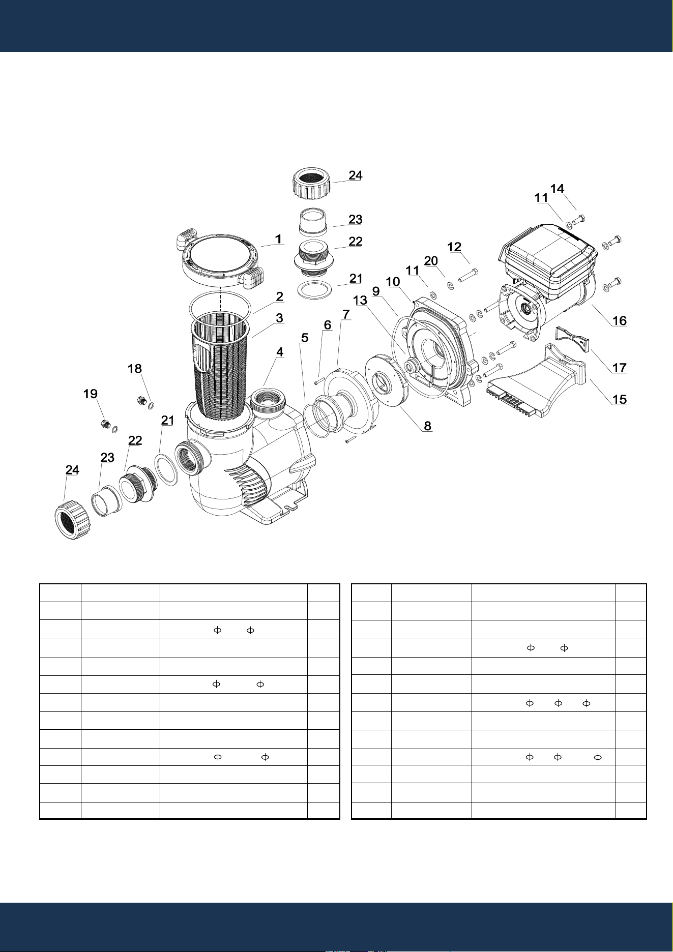
PARTS DIAGRAM
ITEM
1
2
3
4
5
6
7
8
9
10
11
12
PART NO.
47276502
65431042080
647276803001
47276801
65431032080
65212025000
647254703
647277071000
65431045080
647276802
65244015000
65225012000
DESCRIPTION
COVER
O-RING 145* 5
BASKET
PUMP HOUSING
O-RING 85.32* 3.53
SCREW ST4.2*38
DIFFUSER
IMPELLER FOR 75409
O-RING 196.22* 5.33
PUMP COVER
GASKET M10
SCREW 3/8-16*1 1/2 UNC
QTY
1
1
1
1
1
2
1
1
1
1
16
6
ITEM
13
14
15
16
17
18
19
20
21
22
23
24
PART NO.
65028014000
65221008000
65431042080
65023556000
647255302
65432002080
648860105
65244032000
65432096080
647255503080
649130101001
649130102001
DESCRIPTION
SEAL ASSEMBLY
SCREW M10*25
O-RING 145* 5
2.2HP MOTOR FOR 75409
SUPPORTING FOOT
GASKET 19* 13* 1.57
DRAIN PLUG
SPRING WASHER M10
GASKET 77* 59.5* 3
2” TO 1.5” ADAPTOR
2” ADAPTOR
2” NUT ADAPTOR
QTY
1
1
1
1
1
2
2
6
2
2
2
2

DISCLAIMER
DISCLAIMER
PLEASE READ THE FOLLOWING CAREFULLY
The manufacturer and/or distributor have provided the parts list and assembly diagram in this
manual for reference purposes only. They do not make any representation or warranty to the buyer
that they are qualified to make repairs to the product or replace any parts of the product. In fact, the
manufacturer and/or distributor expressly state that all repairs and parts replacements should be
undertaken by certified and licensed technicians, and not by the buyer.
The buyer assumes all risk and liability arising from their repairs to the original product or
replacement parts or arising from their installation of replacement parts. It is strongly advised that
qualified professionals handle any repairs or replacements to ensure safety and proper functioning
of the product. Improper installation and operation may result in injury, property damage, or voiding
of warranty. The manufacturer and/or distributor shall not be held responsible for any accidents,
damages, or malfunctions resulting from the buyer's installation and operation of the product. It is
essential to follow all safety guidelines and recommendations provided in this manual and to seek
professional assistance if unsure about the installation or operation procedures.
CUSTOMER SERVICE
If you have any questions about ordering our pool pumps and replacement parts or pool products,
please feel free to contact us using the following contact information:
Customer Service and Technical Support
Phone: (909) 628-0880
Email: [email protected]
Hours of Operation: Monday – Friday, 9AM – 4PM (CST)
DISCLAIMER
29