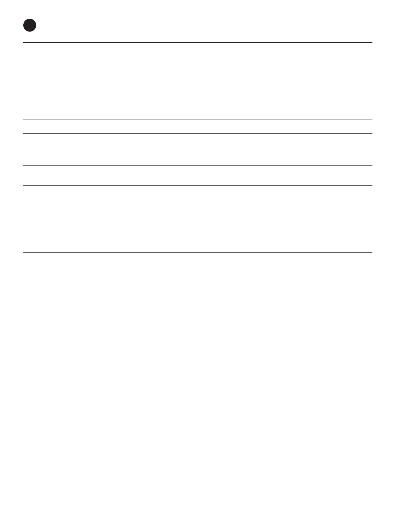
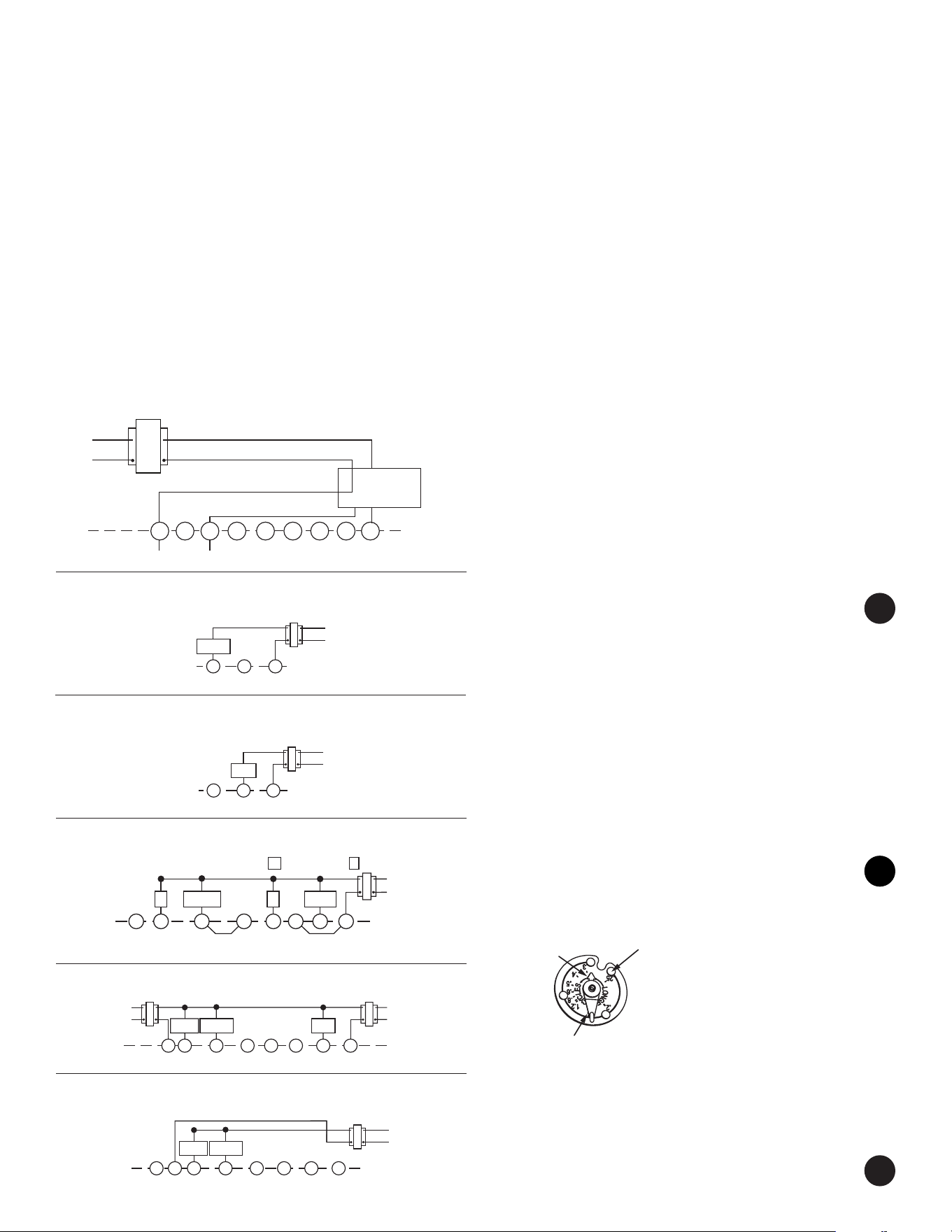
System Models
Standard Heating & Cooling Systems –
4 or 5 wires
Standard Heat Only Systems
Standard Central Air Conditioning
Gas or Oil Heat Yes
Hydronic (Hot Water) Zone Heat – 2 wires
Electric Furnace
Heat Pump (No Aux or Emergency Heat)
Heat Pump (with Aux or Emergency Heat)
Baseboard Electric Heating or Line Voltage No
(120 or 240 Volt)
Millivolt Heat Only Systems –
Floor or Wall Furnaces Yes
Hydronic (Hot Water) Zone Heat – 3 wires
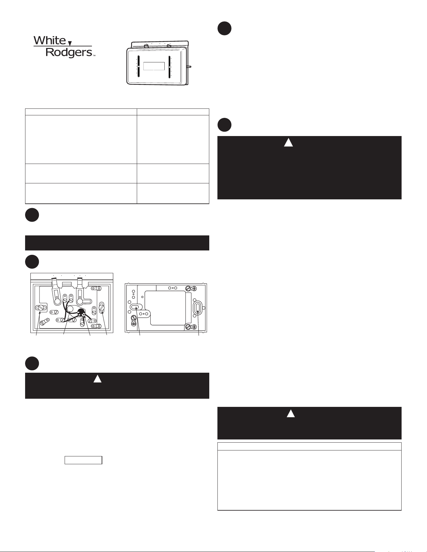
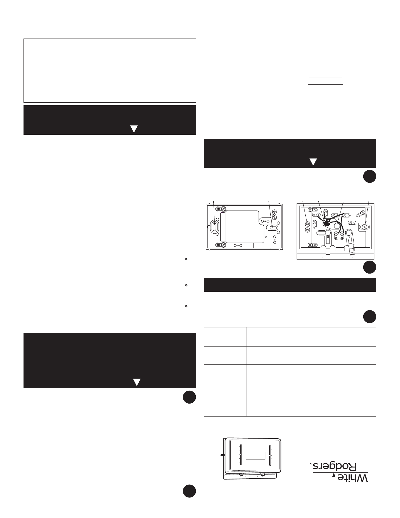
A. Remove base from subbase: Loosen the screws on the base and remove.
B. Mount switching subbase: Use the screws provided to mount the subbase or
wallplate to wall (see Fig. 1).
C. Attach wires to appropriate terminals:
•Fortwowiresystems(HeatOnlyorCoolOnly). Replace subbase with wall-
plate. If you have a two-wire HeatOnly system, attach one wire to R and one to
wire W. If you have a two-wire CoolOnlysystem, attach one wire to R and one to
wire to Y. Tighten any unused terminals securely. (see Fig. 5 and 6).
•Ifyoursystem has more than twowires:Use the cross reference chart to
determine correct wire connections. If you have a four-wire heat/cool system leave
the factory installed jumper between RC and RH attached (see Fig 2.). If your sys-
tem has five wires remove the factory installed jumper between RC and RH(see
Fig 3.).
• Electricheat orsingle stageheat pumpsystems:These thermostats are
configured from the factory to operate a heat/cool, fossil fuel (gas, oil, etc.) forced
air system. This is correct for any system that DOES NOT require the thermostat
to energize the fan on a call for heat. If your system is an electric heat or heat-
pump system that REQUIRES the thermostat to turn on the fan on a call for heat,
remove the yellow factory-installed jumper wire from the Y terminal and connect
it to the A terminal. This will allow the thermostat to energize the fan immediately
on a call for heat. If you are unsure if the heating system requires the thermostat
to control the fan, contact a qualified heating and air conditioning service person.
For single stage heat pump applications (no auxiliary heat), install a short jumper
wire (not included) across terminals W and Y. If the system has a reversing valve
connection energized in Cooling, attach it to O.If the system has a reversing valve
connection energized in Heating, attach it to B (see Fig. 4). This thermostat will not
provide multi-stage heating or cooling.
D. Mount Thermostat Base: Gently push excess wire back into the wall opening
and plug hole with a fire-resistant material, such as fiberglass insulation to prevent
drafts from affecting thermostat operation. Mount the thermostat base to the sub-
base using the three captive screws on the thermostat base. (See Fig. 1) Tighten
the screws securely. Proceed to Step #5.
FAN
ON
AUTO
COOL
OFF
HEAT
SYSTEM
90
90
80
70
60
50
32
°C
21
10
80
70
60
50
32
°C
21
10
InstallationInstructionsfor
Model M150
YOURTHERMOSTATREPLACES
2
1
3
Assemble tools required: power drill, flat blade screwdriver, wire cutter/stripper, level.
Failuretofollowandreadallinstructionscarefullybeforeinstallingoroperat-
ing this control could cause personal injury and/or property damage.
THERMOSTATFEATURES
PREPARATIONS
GRC
Y
W
B
OFF
FAN
AUTO ON
SYSTEM
COOL HEAT
Mounting Screw KEEP THIS AREA
CLEAR OF WIRES
Hole
in Wall
Mounting Screw
ARH
O
6
Y
4
5
R
Mounting Hole
Mounting Hole
Figure1.Thermostatsubbaseandwallplate
To prevent electrical shock and/or equipment damage, disconnect electrical pow-
er to the system at the main fuse or circuit breaker until installation is complete.
CAUTION
!
Before removing wires from old thermostat’s switching subbase, label each wire with
the terminal designation it was removed from.
1. RemoveOldThermostat:A standard heat/cool thermostat consists of three basic
parts:
a. The cover, which may be either a snap-on or hinge type.
b. The base, which is removed by loosening all captive screws.
c. The switching subbase, which is removed by unscrewing the mounting
screws that hold it on the wall or adaptor plate.
Make a note here of the anticipator setting on the old thermostat for
future reference and use in step 5.
The heat anticipator pointer, if adjustable, will be set at one of a series of numbers
representing the current rating of the primary control in your furnace. The number will
be one of the following: .2, .4, .8, etc. or 0.2, 0.4, 0.8, etc.
REMOVINGOLDTHERMOSTAT
REMOVINGOLDTHERMOSTAT(cont’d)
3
If no heat anticipator/indication is showing, do not be concerned; move on to the
next step.
ATTENTION! This product does not contain mercury. However, this product may
replace a unit which contains mercury.
Do not open mercury cells. If a cell becomes damaged, do not touch any spilled
mercury. Wearing non-absorbent gloves, take up the spilled mercury and place into
a container which can be sealed. If a cell becomes damaged, the unit should be
discarded.
Mercury must not be discarded in household trash. When the unit this product is replacing
is to be discarded, place in a suitable container. Refer to www.Thermostat-recycle.org for
location to send product containing mercury.
4
MOUNTINGANDWIRING
Do not use on circuits exceeding specied voltage. Higher voltage will
damage control and could cause shock or fire hazard.
Do not short out terminals on gas valve or primary control to test. Short or
incorrect wiring will damage thermostat and could cause personal injury
and/or property damage.
Thermostat installation and all components of the system shall conform to
ClassIIcircuitspertheNECcode.
Take care when securing and routing wires so they do not short to adjacent
terminalsorrearofthermostat.Personalinjuryand/orpropertydamagemay
occur.
CAUTION
!
TERMINALCROSSREFERENCECHART
NewThermostat OtherManufacturers’
Terminal Designation Terminal Designation
* *
RH 4 RH M R5 R
RC R R V – –
G G G F G G
W W W H 4 W
Y Y Y C Y6 Y
* These are four-wire, single-transformer systems. Factory installed jumper wire
between the RH and RC terminals must remain in place.
PARTNO.37-7266A
1137
www.white-rodgers.com
WARNING
!
Set anticipator to match the setting of your old thermostat you noted in Step 3, or, the
anticipator should be set to match the current rating stamped on your main heating
control. The heat anticipator is adjustable from 0.15 to 1.2 amps. Adjust the anticipa-
tor by rotating the contact arm (see fig. 8). The anticipator setting is indicated by the
numbers on the base that the pointer points to. If you are unsure where to set the
anticipator contact the heater manufacturer for a recommended setting.
Move the pointer counterclockwise to
lengthen heating system cycles; move
clockwise to shorten heating cycles.
Adjustments should not be greater than
1/2 marking at a time.
For millivolt operation, rotate contact arm to
Millivolt Link.
Snap on Cover: Carefully align the cover
with the base and snap the cover onto
the base.
5
6
7
SETHEATANTICIPATOR
Figure8.Anticipatoradjustment
Figure 5. Anticipator adjustment
Rotate contact arm
to adjust heat anticipator
Arrow points to the
current rating of
the primary control
Figure 5. Anticipator adjustment
Millivolt Link
NEWTHERMOSTATOPERATION
Thermostat on Subbase. After power is turned on, use the system switch to select
either heating or cooling, or to turn the heating/cooling system off. Use the fan switch
to control fan operation. When the fan switch is in the AUTOposition, the fan will
cycle with the heating or cooling system (the fan will not run if the system switch is
in the OFFposition and the fan switch is in the AUTOposition). When the fan switch
is in the ONposition, the fan will run continuously, regardless of system switch posi-
tion (even if the system switch is set to OFF,the fan will run if the fan switch is in the
ONposition).
Thermostat on wallplate. For heat only move the temperature lever to the highest
temperature. For cool only move the temperature lever to the lowest temperature.
SPECIFICATIONS
ELECTRICALDATA
Switch Rating...................................... 24 VAC (30 VAC max.)
Heating.................................................. 0.15 to 1.2 Amps
Cooling.................................................. 0 to 1.5 Amps
Anticipator Rating:
Heating.................................................. Adjustable from 0.15 to 1.2 Amps
Cooling.................................................. Fixed
THERMALDATA:
Temperature Range............................. 50°F to 90°F (10°C to 32°C)
OperatingHumidityRange................. 0 – 90% noncondensing
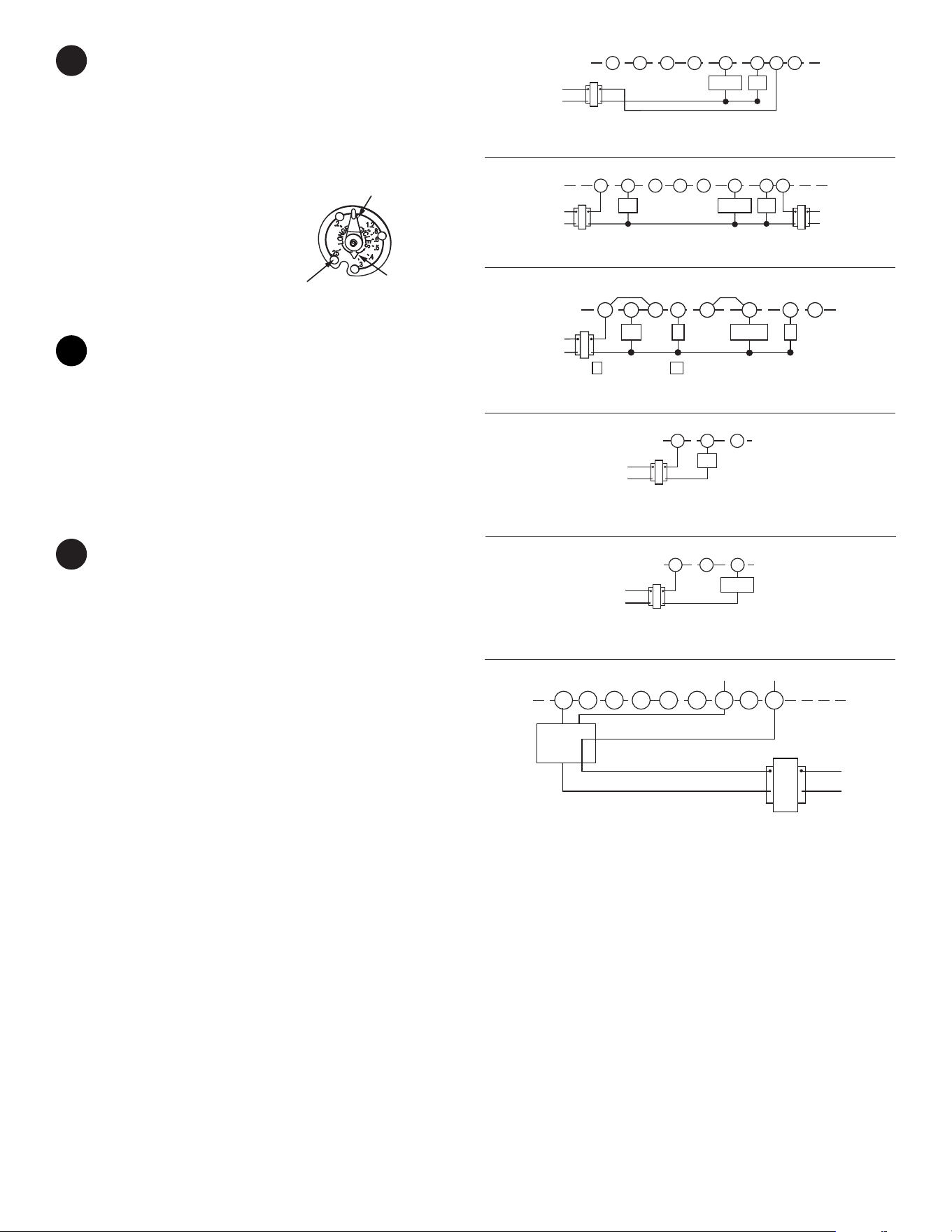
Figure2.Typicalwiringforsingletransformerheating/coolingsystem
RH W B O Y G RC A
24 VAC
120 VAC
Hot
Neutral
TRANSFORMER
Compressor
Relay
Fan
Relay
Figure 2. Typical wiring for single transformer
heating/cooling system
Figure 3. Typical wiring for two-transformer
heating/cooling system
RH W B O Y GA
24 VAC
120 VAC
Hot
Neutral
TRANSFORMER
Heat
Relay
Compressor
Relay
Fan
Relay
24 VAC
120 VAC
Hot
Neutral
TRANSFORMER
RC
Figure3.Typicalwiringfortwo-transformerheating/coolingsystem
Figure 4. Typical wiring for single transformer,
single stage heat pump system
W BO YG A
24 VAC
120 VAC
Hot
Neutral
TRANSFORMER
Compressor
Relay
Fan
Relay
* * *
Factory-Installed Jumper
* * *
Te rminal energized
in cooling
Te rminal energized
in heating
RH
Field-Installed Jumper
RC
Figure4.Typicalwiringforsingletransformer,singlestageheatpumpsystem
Figure5.Typicalwiringforsingletransformerheatingsystem
TRANSFORMER
R YW
24 VAC
120 VAC
Hot
Neutral
Heat
Relay
WR
24 VAC
120 VAC
Hot
Neutral
TRANSFORMER
Y
Compressor
Relay
Figure6.Typicalwiringforsingletransformercoolingsystem
Figure7.Typicalwiringdiagramheatonly,3-wirezonevalvesystems
6
MV
B
O
Y G W RC
THERMOSTAT
Hot
120 VAC
24 VAC
Neutral
TRANSFORMER
SYSTEM
Zone
Valve
6 4
5
21
RH
www.white-rodgers.com
8
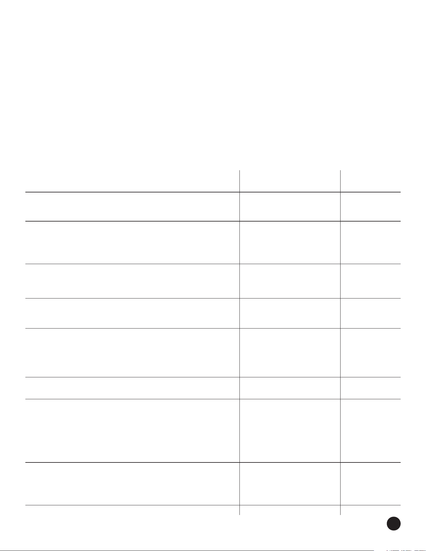
TROUBLESHOOTING
Symptom PossibleCause CorrectiveAction
NoHeat/NoCool/NoFan
1. Blown fuse or tripped circuit breaker. Replace fuse or reset breaker.
(commonproblems)
2. Furnace power switch to OFF. Turn switch to ON.
3. Furnace blower compartment door or Replace door panel in proper position to engage
panel loose or not properly installed. safety interlock or door switch.
NoHeat
1. Pilot light not lit. Re-light pilot.
2. Broken or melted anticipator wire. Excessive current or dead short in system. Have a qualified service person check the system before
replacing thermostat.
3. Loose connection to thermostat or system. Verify thermostat and system wires are securely attached.
4. Thermostat or heating system requires Your furnace manufacturer or service person can describe how to test the heating system to verify it is
replacement or service. operating correctly. If the heating system is capable of operation and the no heat condition persists,
replace the thermostat.
5. System Switch not set to Heat. Set System Switch to Heat and raise temp above room temp.
IntermittentHeat
1. Furnace Lock-Out Condition Many furnaces have safety devices that shut the system down when a lock-out condition occurs. If the
heat works intermittently contact the furnace manufacturer or local service person for assistance.
NoCool
1. Loose connection to thermostat or system. Verify thermostat and system wires are securely attached.
2. Thermostat or cooling system requires Your cooling system manufacturer or service person can describe how to test the cooling system to
replacement or service. verify it is operating correctly. If the cooling system is capable of operation and the no cooling condition
persists, replace the thermostat.
3. System Switch not set to Cool. Set System Switch to Cool and lower temp below room temp.
Heat,CoolorFanRuns
1. Possible short in wiring. Check each wire connection to the thermostat to verify it is neatly looped under the terminals. No extra
Constantly.
2. Possible short in thermostat. wire should stick out from under the terminals.
3. Possible short in heat/cool/fan system.
FurnaceCyclesTooFast
See Step 5, Adjusting the Anticipator. The anticipation setting is the only adjustment that effects the heating cycle rate. If an acceptable cycle rate
orTooSlowNarrowor
is not achieved using the anticipator contact a local service person for additional suggestions. The location of
wide temperature swing
the thermostat, size of the Heat/Cool System and current draw can influence the cycle rate.
CoolingCyclesTooFast
1. Poor thermostat location for sensing room The cycle rate for cooling can not be adjusted. The location of the thermostat, size of the Cool system and
orTooSlow(narrowor
temperature. current draw can influence the cycle rate. Contact a local service person for suggestions.
widetemperatureswing)
2. Cooling system over or undersized.
3. Excessive Current draw influencing thermostat.
Thermostat Setting and
1. Thermostat thermometer setting requires The thermometer can be adjusted by using a standard slotted screwdriver. Turn the thermometer pointer
Thermostat Thermometer
adjustment. screw located inside the front cover to change the setting. For calibrating the setting lever contact a local
Disagree
2. Thermostat setting lever requires calibration. heating and cooling service person.
Adjusting Thermometer
1. Thermostat thermometer disagrees with The thermometer on the thermostat is accurately calibrated at our factory but you can adjust it by using a
other room thermometers. standard slotted screwdriver. Turn the thermometer pointer screw located inside the front cover to change
the setting.
www.white-rodgers.com
www.white-rodgers.com
White-Rodgers is a division
of Emerson Electric Co.
www.white-rodgers.com
White-Rodgers es una división
de Emerson Electric Co.
8
SOLUCIÓN DE PROBLEMAS
Síntoma Causa posible Acción correctiva
El sistema no calienta/
El sistema no enfría/No
funciona el ventilador
(problemas comunes)
1. Se quemó el fusible o se disparó el disyuntor.
2. El interruptor de alimentación del calefactor
está en OFF.
3. La puerta o el panel del compartimento del
soplador del calefactor están sueltos o no
están debidamente instalados.
Cambie el fusible o vuelva a activar el disyuntor.
Coloque el interruptor en ON.
Vuelva a colocar el panel de la puerta en el lugar correcto para que se
enganche con el interruptor de interbloqueo de seguridad o de la puerta.
El sistema no calienta
1. La luz piloto no está encendida.
2. Cable de anticipador roto o fundido.
3. La conexión al termostato o al sistema
está suelta.
4. El sistema de calefacción requiere servicio
técnico o debe cambiarse el termostato.
5. El interruptor System no está ajustado
en Heat.
Vuelva a encender el piloto.
Corriente excesiva o cortocircuito total en el sistema. Pida a un técnico calificado que revise el sistema
antes de cambiar el termostato.
Verifique que los cables del termostato y del sistema estén bien conectados.
El fabricante o técnico de su calefactor pueden explicarle cómo probar el sistema de calefacción para veri-
ficar si está funcionando correctamente. Si el sistema de calefacción funciona y persiste la condición
de no calor, cambie el termostato.
Ajuste el interruptor System en Heat y suba la temperatura de referencia por encima
de la temperatura ambiente.
Calor intermitente
1. Condición de bloqueo de calefactor. Muchos calefactores tienen dispositivos de seguridad que se cierran cuando se produce una condición
de bloqueo. Si la calefacción funciona de manera intermitente, póngase en contacto con el fabricante del
calefactor o con el personal técnico local para solicitar ayuda.
El sistema no enfría
1. La conexión al termostato o al sistema
está suelta.
2. El sistema de enfriamiento requiere servicio
técnico o debe cambiarse el termostato.
3. El interruptor System no está ajustado
en Cool.
Verifique que los cables del termostato y del sistema estén bien conectados.
El fabricante o técnico de su sistema de enfriamiento pueden explicarle cómo probar el sistema para
verificar si está funcionando correctamente. Si el sistema de enfriamiento funciona y persiste la condición
de no enfriamiento, cambie el termostato.
Coloque el interruptor System en Cool y baje la temperatura de referencia por debajo
de la temperatura ambiente.
El modo de calor, frío o
ventilador funciona de
manera constante
1. Posible cortocircuito en los cables.
2. Posible cortocircuito en el termostato.
3. Posible cortocircuito en el sistema de calor/
frío/ventilador.
Revise la conexión de cada cable al termostato para asegurarse de que esté debidamente enroscada
debajo de las terminales. Los cables no deben sobresalir por debajo de las terminales.
Los ciclos del calefactor
son demasiado largos
o demasiado cortos
oscilación reducida o
amplia de la temperatura
Vea el paso 5, Ajuste del anticipador. El ajuste de anticipación es el único ajuste que afecta la velocidad del ciclo de calefacción. Si no se
obtiene una duración de ciclo aceptable usando el anticipador, póngase en contacto con el personal técnico
local para que le sugiera otras soluciones. La ubicación del termostato, el tamaño del sistema
de calor/frío y la toma de corriente pueden influir en la oscilación reducida o velocidad del ciclo.
Los ciclos de enfriamiento
son demasiado largos
o demasiado cortos
(oscilación reducida o
amplia de la temperatura)
1. Mala ubicación del termostato para detectar
temperatura ambiente.
2. Sistema de enfriamiento demasiado pequeño
o demasiado grande.
3. La toma excesiva de corriente afecta
el termostato.
La duración del ciclo de enfriamiento es fija y no se puede ajustar. La ubicación del termostato y el tamaño
del sistema de enfriamiento pueden influir en la duración del ciclo. Póngase en contacto con el personal
técnico local para que le sugiera otras soluciones.
El ajuste del termostato no
coincide con el termómetro
1. Es necesario ajustar el termómetro
del termostato.
2. La palanca de ajuste del termostato
requiere calibración.
El termómetro puede ajustarse utilizando un destornillador ranurado común. Gire el tornillo indicador
del termómetro ubicado dentro de la cubierta delantera para modificar el ajuste. Para calibrar la palanca
de ajuste, póngase en contacto con el personal técnico local especializado en sistemas de calefacción
y enfriamiento.
Ajuste del termómetro
1. El termómetro del termostato no coincide con
otros termómetros de la habitación.
El termómetro del termostato viene calibrado con precisión de fábrica pero puede ajustarlo utilizando un
destornillador ranurado común. Gire el tornillo indicador del termómetro dentro de la cubierta delantera
para modificar el ajuste.
www.white-rodgers.com
Ajuste el anticipador en el valor del termostato viejo que anotó en el paso 3, o bien
en el valor de corriente nominal que figura en su control de calefacción principal.
El anticipador de calor puede ajustarse de 0.15 a 1.2 A. Ajuste el anticipador girando
el brazo de contacto (vea la figura 8). El ajuste del anticipador está indicado por los
números de la base a los que apunta el indicador. Si no está seguro en qué valor
ajustar el anticipador, consulte al fabricante del calefactor el valor recomendado.
Mueva el indicador en sentido antihorario
para alargar los ciclos de calefacción
del sistema; muévalo en sentido horario
para acortar los ciclos de calefacción.
Los ajustes no deben ser de más de
1/2 marca a la vez.
Para el funcionamiento milivoltio, gire el
brazo de contacto a Conexión de milivoltio.
Cubierta tipo broche: A linee con cuidado
la cubierta con la base y engánchela en
la base.
5
6
7
AJUSTE DE ANTICIPADOR DE CALOR
Figura 8. Ajuste del anticipador
Figure 5. Anticipator adjustment
Gire el brazo de contacto para
ajustar el anticipador de calor
La flecha apunta a
la corriente nominal
del control principal
Figura 5. Ajuste del anticipador
Conexión
de milivoltio
FUNCIONAMIENTO DEL NUEVO TERMOSTATO
Termostato montado en subbase. Una vez encendida la alimentación, utilice el
interruptor del sistema para seleccionar calefacción o enfriamiento, o para apagar
el sistema de calefacción/enfriamiento. Utilice el interruptor del ventilador para
controlar el funcionamiento del ventilador. Cuando el interruptor del ventilador
se encuentra en la posición AUTO, el ventilador se encenderá y apagará con el
sistema de calefacción o enfriamiento (no funcionará si el interruptor del sistema
está en la posición OFF y el interruptor del ventilador en la posición AUTO). Cuando
el interruptor del ventilador está en la posición ON, el ventilador funcionará de forma
continua, independientemente de la posición del interruptor del sistema (aunque el
interruptor del sistema esté ajustado en OFF, el ventilador funcionará si el interruptor
del ventilador está en la posición ON).
Termostato montado en pared. Para sólo calor, mueva la palanca de temperatura
a la temperatura más alta. Para sólo frío, mueva la palanca de temperatura a la
temperatura más baja.
ESPECIFICACIONES
DATOS ELÉCTRICOS
Características del interruptor ........................... 24 VCA (30 VCA máx.)
Calefacción ........................................................... 0.15 a 1.2 A
Enfriamiento .......................................................... 0 a 1.5 A
Características del anticipador:
Calefacción ........................................................... Ajustable de 0.15 a 1.2 A
Enfriamiento .......................................................... Fijo
DATOS TÉRMICOS:
Rango de temperatura de referencia ................. 50°F a 90°F (10°C a 32°C)
Rango de humedad operativa ............................ 0 a 90 % sin condensación
Figura 2. Diagrama de conexiones típico para sistema
de calor/frío de un solo transformador
RH W B O Y G RC A
24 VCA
120 VCA
Vivo
Neutro
TRANSFORMADOR
Relé del
compresor
Relé del
ventilador
Figura 2. Diagrama de conexiones típico para sistema
de calor/frío de un solo transformador
Figura 3. Diagrama de conexiones típico para sistema
de calor/frío de dos transformadores
RH W B O Y GA
24 VCA
120 VCA
Vivo
Neutro
TRANSFORMADOR
Relé
de calor
Relé del
compresor
Relé del
ventilador
24 VCA
120 VCA
Vivo
Neutro
TRANSFORMADOR
RC
Figura 3. Diagrama de conexiones típico para sistema
de calor/frío de dos transformadores
Figura 4. Conexión típica para sistemas de bomba de calor
de un solo transformador y una sola etapa
W BO YG A
24 VCA
120 VCA
Vivo
Neutro
TRANSFORMADOR
Relé del
compresor
Relé del
ventilador
* * *
Puente instalado en fábrica
* * *
Terminal energizada
en enfriamiento
Terminal energizada
en calefacción
RH
Puente instalado en lugar de uso
RC
Figura 4. Conexión típica para sistemas de bomba de calor
de un solo transformador y una sola etapa
Figura 5. Conexión típica para sistemas de calor
de un solo transformador
TRANSFORMADOR
R YW
24 VCA
120 VCA
Vivo
Neutro
Relé
de calor
WR
24 VCA
120 VCA
Vivo
Neutro
TRANSFORMADOR
Y
Relé del
compresor
Figura 6. Conexión típica para sistemas de frío
de un solo transformador
Figura 7. Conexión típica para sistemas de válvula zonificada
de 3 cables de solo calor
6
MV
B
O
Y G W RC
TERMOSTATO
Vivo
120 VCA
24 VCA
Neutro
TRANSFORMADOR
SISTEMA
Válvula
zonificada
6 4
5
21
RH
www.white-rodgers.com
Sistema
Sistemas de calor/frío estándar- 4 o 5 cables
Sistemas de sólo calor estándar
Aire acondicionado central estándar
Sistemas de calefacción de gas o aceite Sí
Calefacción zonificada hidrónica
(agua caliente) – 2 cables
Calefactor eléctrico
Bomba de calor (sin calor auxiliar o de emergencia)
Bomba de calor (con calor auxiliar o de emergencia)
Calefacción eléctrica de borde inferior o voltaje No
de línea (120 ó 240 voltios)
Sistemas de sólo calor milivoltios -
Calefactores de piso o pared Sí
Calefacción zonificada hidrónica (agua caliente) – 3 cables
A. Retire la base de la subbase: Afloje los tornillos de la base y retírela.
B. Monte la subbase de conmutación: Utilice los tornillos suministrados para
montar la subbase o la placa de pared en la pared (vea la figura 1).
C. Conecte los cables a las terminales correspondientes:
•
Para sistemas de dos cables (sólo calor o sólo frío). Reemplace la subbase por
la placa de pared. Si tiene un sistema de sólo calor de dos cables, conecte un cable
a R y el otro a W. Si tiene un sistema de sólo frío de dos cables, conecte un cable a
R y el otro a Y. Ajuste bien las terminales no utilizadas (vea las figuras 5 y 6).
• Si su sistema tiene más de dos cables: Consulte en el cuadro de referencia
para determinar las conexiones correctas. Si tiene un sistema de frío/calor de
cuatro cables, deje conectado el puente instalado en fábrica entre RC y RH (vea
la figura 2). Si su sistema tiene cinco cables, retire el puente instalado en fábrica
entre RC y RH (vea la figura 3).
• Sistemas de calor eléctricos o de bomba de calor de una sola etapa:
Estos termostatos están configurados de fábrica para operar un sistema de aire
forzado con combustible fósil (gas, aceite, etc.) de calor/frío. Está correctamente
configurado para cualquier sistema que NO requiera que el termostato energice
el ventilador en una llamada de calor. Si su sistema es un sistema eléctrico o
de bomba de calor que REQUIERE que el termostato encienda el ventilador en
una llamada de calor, retire el cable de puente amarillo instalado en fábrica de
la terminal Y y conéctelo a la terminal A. Esto permitirá al termostato energizar
el ventilador inmediatamente en una llamada de calor. Si no está seguro si
el sistema de calefacción requiere que el termostato controle el ventilador,
póngase en contacto con un servicio técnico de calefacción y aire acondicionado
calificado. En el caso de aplicaciones de bomba de calor de una sola etapa
(sin calor auxiliar), instale un cable de puente corto (no incluido) entre las
terminales W y Y. Si el sistema tiene una conexión de válvula inversora
energizada en frío, conéctelo a O. Si el sistema tiene una conexión de válvula
inversora energizada en calor, conéctelo a B (vea la figura 4). Este termostato no
proporcionará calefacción o enfriamiento multietapa.
D. Fije la base del termostato a la pared: Empuje con cuidado el cable que
sobresale hacia el interior de la pared y tape el orificio con un material resistente
al fuego (como aislamiento de fibra de vidrio) para evitar que las corrientes de
aire afecten el funcionamiento del termostato. Monte la base del termostato
a la subbase utilizando los tres tornillos cautivos de la base del termostato
(vea la figura 1). Ajuste bien los tornillos. Continúe con el paso Nº5.
Ventila dor
ON
AUTO
COOL
OFF
HEAT
SISTEMA
90
90
80
70
60
50
32
C
21
10
80
70
60
50
32
C
21
10
Instrucciones de instalación para el
Modelo M150
SU TERMOSTATO REEMPLAZA
2
1
3
Reúna las herramientas requeridas: taladro eléctrico, destornillador de hoja plana,
tenazas/desaislador, nivel.
El no leer y seguir con cuidado todas las instrucciones antes de instalar o
utilizar este control podría causar lesiones personales y/o daños materiales.
DETALLES DEL TERMOSTATO
PREPARACIÓN
GRC
Y
W
B
OFF
Ventilador
AUTO ON
SISTEMA
COOL HEAT
Tornillo
de montaje
MANTENGA ESTE
LUGAR LIBRE DE CABLES
Orificio en
la pared
Tornillo
de montaje
ARH
O
6
Y
4
5
R
Orificio de montaje
Orificio de montaje
Figura 1. Subbase y placa de pared del termostato
Para evitar descargas eléctricas y/o daños al equipo, desconecte la alimentación
eléctrica al sistema en la caja de fusibles o disyuntores principal hasta que haya
finalizado la instalación del sistema.
¡PRECAUCIÓN!
!
Antes de retirar los cables de la subbase de conmutación del termostato viejo,
identifique cada cable con la designación de la terminal de la que lo desconectó.
1. Retire el termostato viejo: Un termostato de calor/frío estándar consta de tres
partes básicas:
a. La cubierta, que puede ser tipo bisagra o de broche.
b. La base, que se retira aflojando todos los tornillos cautivos.
c. La subbase de conmutación, que se retira desenroscando los tornillos de
montaje que la sujetan a la pared o a la placa adaptadora.
Tome nota aquí del ajuste del anticipador del termostato viejo para
referencia futura y para utilizarlo en el paso 5.
El indicador del anticipador de calor, si es ajustable, se ajustará en uno de una serie
de números que representan la corriente nominal del control principal de su calefactor.
El número será uno de los siguientes: .2, .4, .8, etc. o 0.2, 0.4, 0.8, etc.
CÓMO RETIRAR EL TERMOSTATO VIEJO
CÓMO RETIRAR EL TERMOSTATO VIEJO
(continuación)
3
Si no aparece un anticipador de calor o una indicación, no se preocupe y continúe
con el siguiente paso.
¡ATENCIÓN! Este producto no contiene mercurio. No obstante, puede reemplazar
un producto que sí contiene mercurio.
No abra las celdas de mercurio. En el caso de que una celda se dañe, no toque el
mercurio derramado. Usando un par de guantes no absorbentes, recoja el mercurio
derramado y viértalo en un recipiente que pueda sellarse. Si se daña una celda,
debe desecharse la unidad.
El mercurio no debe desecharse con los residuos domésticos. Para desechar la uni-
dad que será reemplazada por este equipo, colóquela en un recipiente adecuado.
En www.Thermostat-recycle.org se proporciona una lista de los lugares a los que se pu-
eden enviar los productos que contienen mercurio.
4
MONTAJE Y CONEXIONES ELÉCTRICAS
No utilizar en circuitos que excedan el voltaje especificado ya que los voltajes más
altos dañarán el control y pueden causar riesgos de electrocución o incendio.
No cortocircuite las terminales de la válvula de gas ni del control principal para
probarlos. Un cortocircuito o una conexión incorrecta dañarán el termostato y
podría causar lesiones personales y/o daños materiales.
La instalación del termostato y de todos los componentes del sistema de control
debe ajustarse a las normas del código NEC para los circuitos Clase II.
¡ADVERTENCIA!
!
Tenga cuidado al fijar y pasar los cables para que no hagan cortocircuito
con las terminales adyacentes o con la parte trasera del termostato, ya que
podrían causar lesiones personales y/o daños materiales.
¡PRECAUCIÓN!
!
CUADRO DE REFERENCIA DE TERMINALES
Designación de la terminal Designación de la terminal
del nuevo termostato de otros fabricantes
* *
RH 4 RH M R5 R
RC R R V – –
G G G F G G
W W W H 4 W
Y Y Y C Y6 Y
*
Éstos son sistemas de un solo transformador y cuatro cables. El cable de puente
instalado en fábrica entre las terminales RH y RC debe dejarse en su lugar.
Nº DE PIEZA 37-7266A
1137
www.white-rodgers.com