Servicing should only be performed by a Qualified Service TECHNICIAN
Kit Instructions
COMMON VENT KIT (PVC AND DURAVENT)
100336248_2000539084B
PRINTED 0122
CONTENTSCONTENTS
INTRODUCTION ................................................................2
Models Covered .............................................................. 2
Additional Information ..................................................... 3
PVC COMMON VENT KIT INSTRUCTIONS
(100227396 OR 100223775)................................................4
PVC Parts List ................................................................ 4
Instructions ..................................................................... 6
Assembly ........................................................................ 9
POLYPROPYLENE COMMON VENT KIT INSTRUCTIONS
(100227395 OR 100223774) .............................................12
Polypropylene Parts List ................................................ 12
Instructions .................................................................... 14
Assembly ....................................................................... 15

2
INTRODUCTIONINTRODUCTION
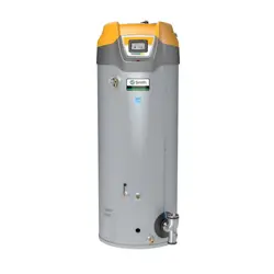
These instructions cover how to install the 120, 150 to 250 models or 300 to 500 models of water heaters in a common direct
vent kit. You may not combine water heaters from different groups. This kit may be used as part of a common vent installation of
up to three 120 models or up to three of any combination of the models in the 150 to 250 group or the 300 to 500 group listed in
Models Covered
(page 2) in a direct vent configuration.
Check local code requirements regarding common venting of plastic pipe. In Canada, all plastic pipe must be listed to
ULC S636
.
MODELS COVERED
120 MODELS, SERIES 200/201/300/301/350
• A. O. SMITH MODELS: BTH 120(A)
• American Models: (A)HCG3 60T120 3 (N),(P)
• State Models: SUF 60120(N,P)E(A)
150 TO 251 MODELS, SERIES 200/201/300/301/350
• A. O. SMITH MODELS:
∙ BTH 150(A)
∙ BTH 199(A)
∙ BTH 250(A)
∙ BTH 251(N)A
∙ BTHL 150 (A)
∙ BTHL 199 (A)
∙ BTHL 250 (A)
• American Models:
∙ (A)HCG3100T 150
∙ (A)HCG3100T 199
∙ (A)HCG3100T 250
∙
• State Models:
∙ SUF 100150(N,P)E(A)
∙ SUF 100199(N,P)E(A)
∙ SUF 100250(N,P)E(A)
∙ SUF 119251(N)EA
∙ SUFL 250150(N,P)A
∙ SUFL 250199(N,P)A
∙ SUFL 250250(N,P)A

3
• Reliance Models:
∙ RUF 100199(N,P)E
300 TO 500 MODELS, SERIES 200/201/300/301/350
• A. O. SMITH MODELS:
∙ BTH 300 (A)
∙ BTH 400 (A)
∙ BTH 500 (A)
∙ BTHL 300A
∙ BTHL 400A
∙ BTHL 500A
• American Models:
∙ (A)HCG3119T 300
∙ (A)HCG3119T 400
∙ (A)HCG3119T 500
• State Models:
∙ SUF 119300(N,P)E(A)
∙ SUF 119400(N,P)E(A)
∙ SUF 119500(N,P)E(A)
∙ SUFL 220300(N,P)EA
∙ SUFL 220400(N,P)VA
∙ SUFL 220500(N,P)EA
Note: These instructions are included with a kit that connects one water heater to a common vent system. Study this instruction
to determine how many kits you may need for your installation.
ADDITIONAL INFORMATION
This kit instruction is a supplement to the Instruction Manual that is supplied with the water heater. The multiple heater installation
must satisfy all the requirements of the Instruction Manual as well as the requirements of this kit instruction. The installer may
also consult with installation instructions from the vent manufacturer. In the event of any conflict between the documents, these
instructions take precedence.
Installations must comply with applicable national, state, and local codes. Check local code requirements regarding the use of
PVC pipe. In Canada, all plastic pipe must be listed to
ULC S636
.
NOTE: The use of cellular core PVC (
ASTM F891
), cellular core CPVC, or Radel® (polyphenolsulfone) in non-metallic venting system
is prohibited. Covering non-metallic vent pipe and fittings with thermal insulation is prohibited.
4
PVC COMMON VENT KIT INSTRUCTIONS PVC COMMON VENT KIT INSTRUCTIONS
(100227396 OR 100223775)(100227396 OR 100223775)
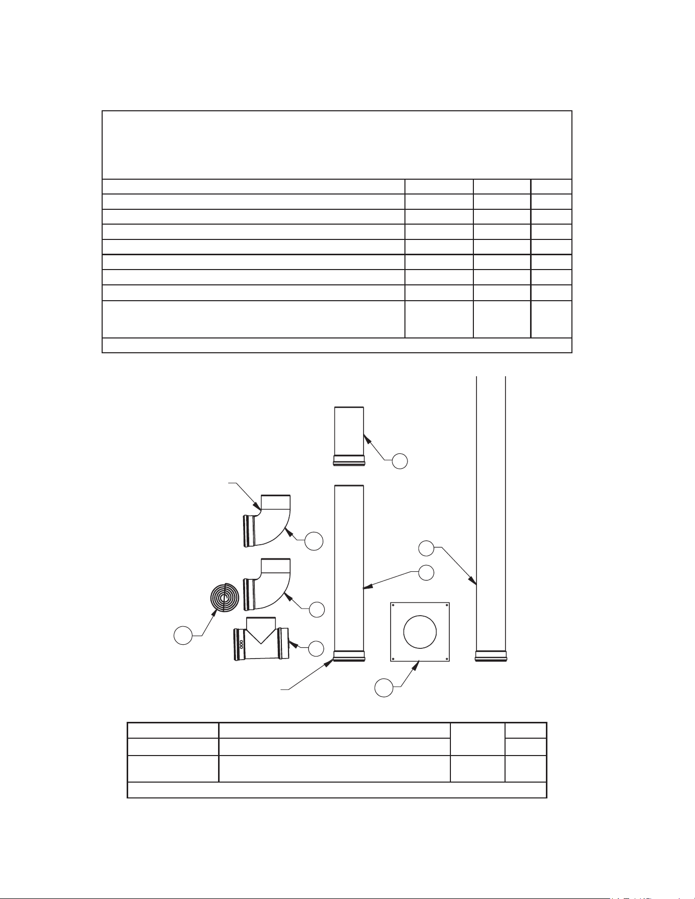
PVC PARTS LIST
Each kit contains the adapters needed to connect the vent and air intake system to one heater. Additional parts are needed to
create the connectors, common sections and vent terminations. A list of additional parts is included below for your convenience.
For example, to install a common vent for two heaters requires two common vent kits (see
Table 1
and
Table 2
), the additional
parts listed in
Table 3
or
Table 4
, and the necessary PVC parts selected to fit the installation.
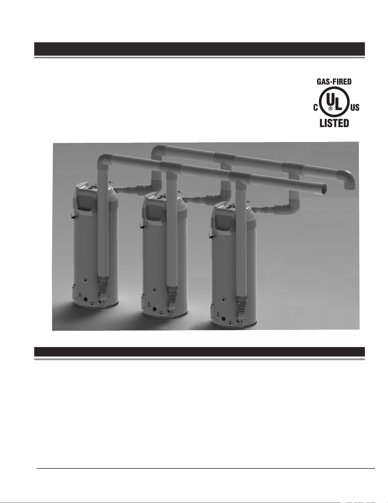
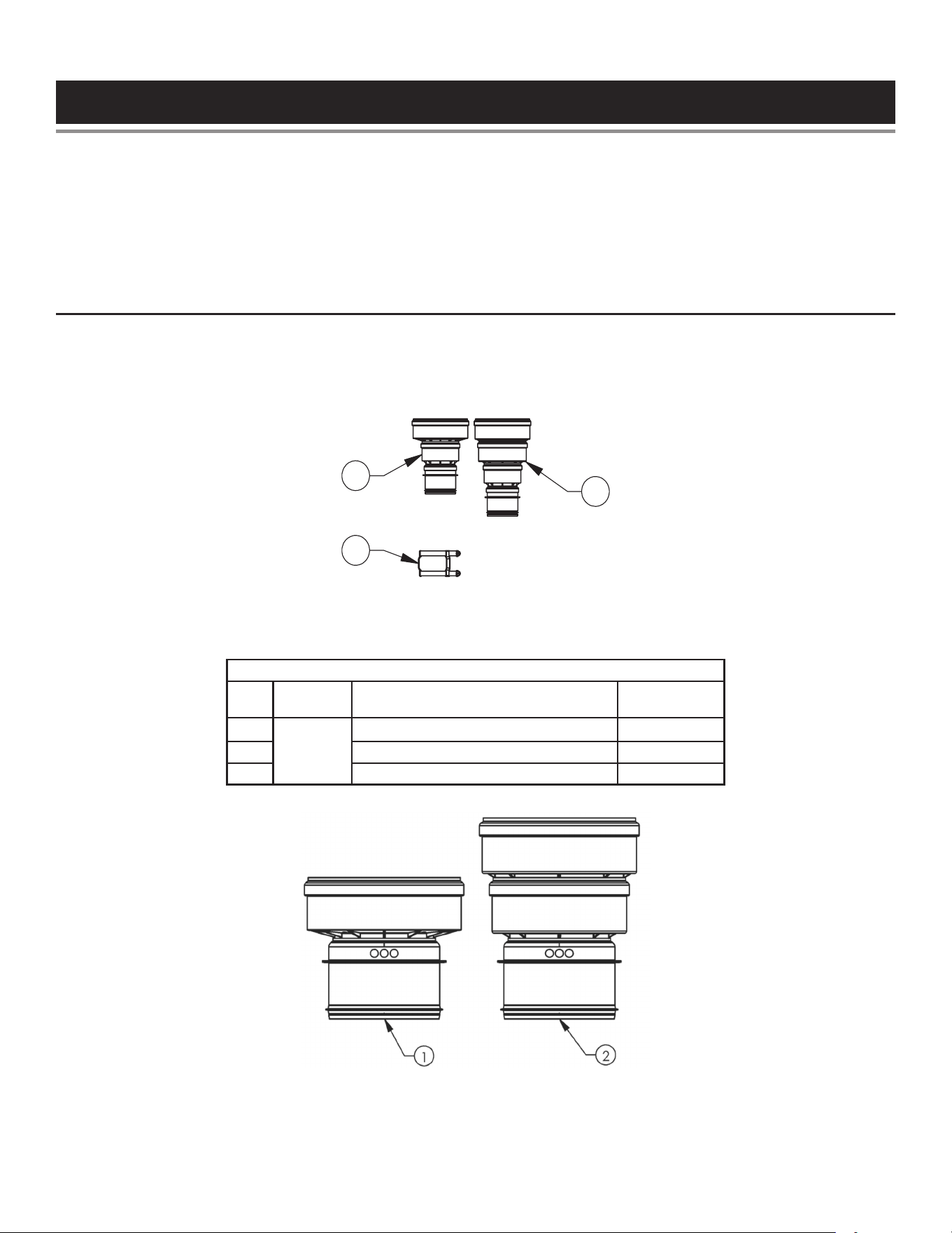
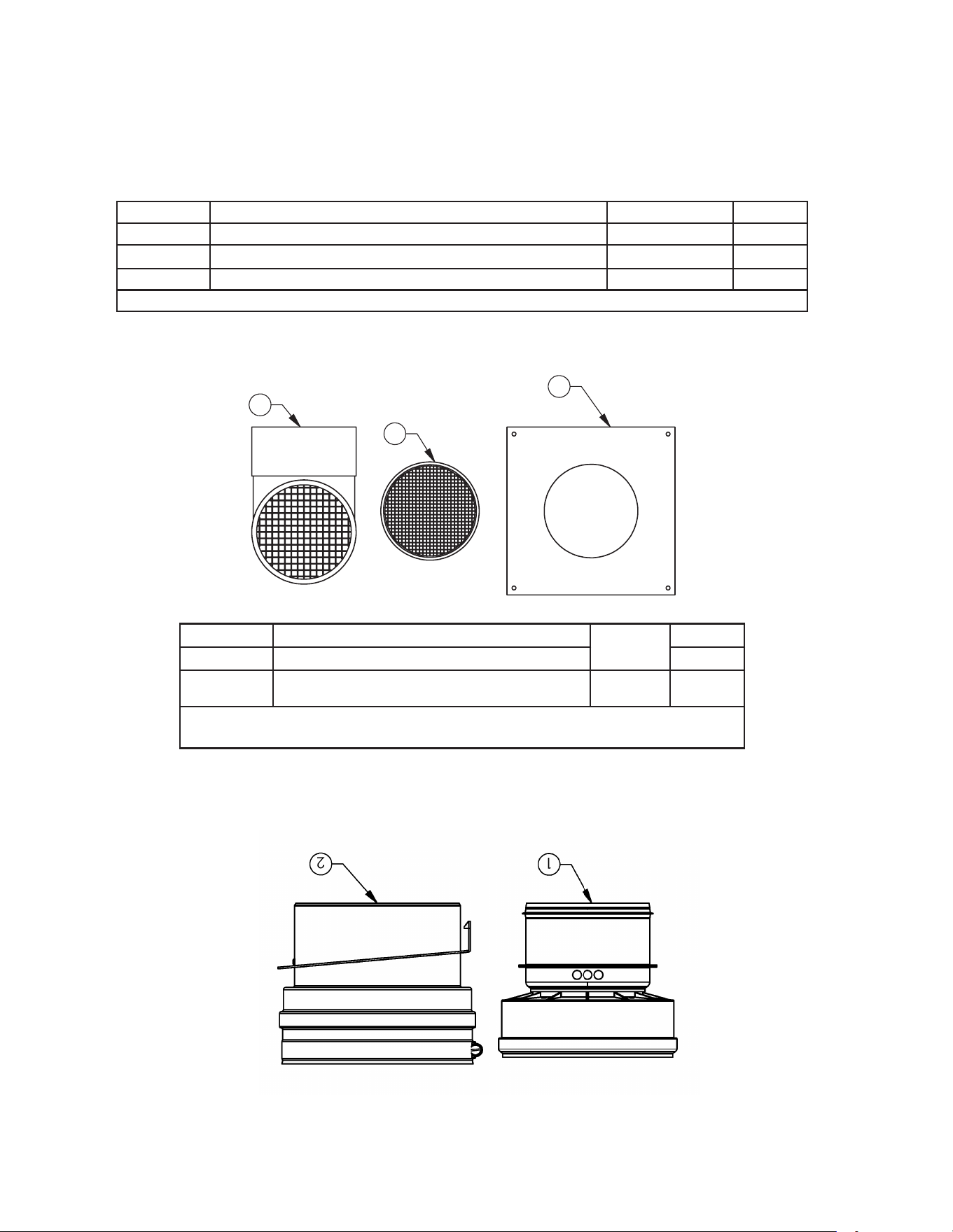
Figure 1. PVC COMMON VENT KIT (120 TO 250 MODELS)
(ONE KIT NEEDED FOR EACH HEATER)
Table 1. PVC COMMON VENT KIT PARTS LIST (120 TO 250 MODELS)
Item
No.
Kit
No.
Description
Kit
Supplied
1
100227396
VENT ADAPTER,OUTLET,6”,PP,DURAVENT 1
2 VENT ADAPTER,PP/PVC,STAINLESS,DURAVENT 1
3 INSTRUCTION,COMMON VENT KIT 1
5
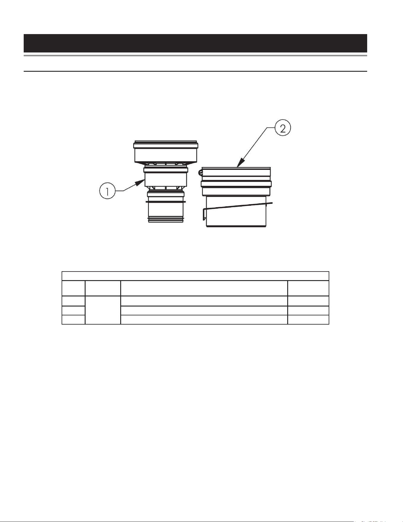
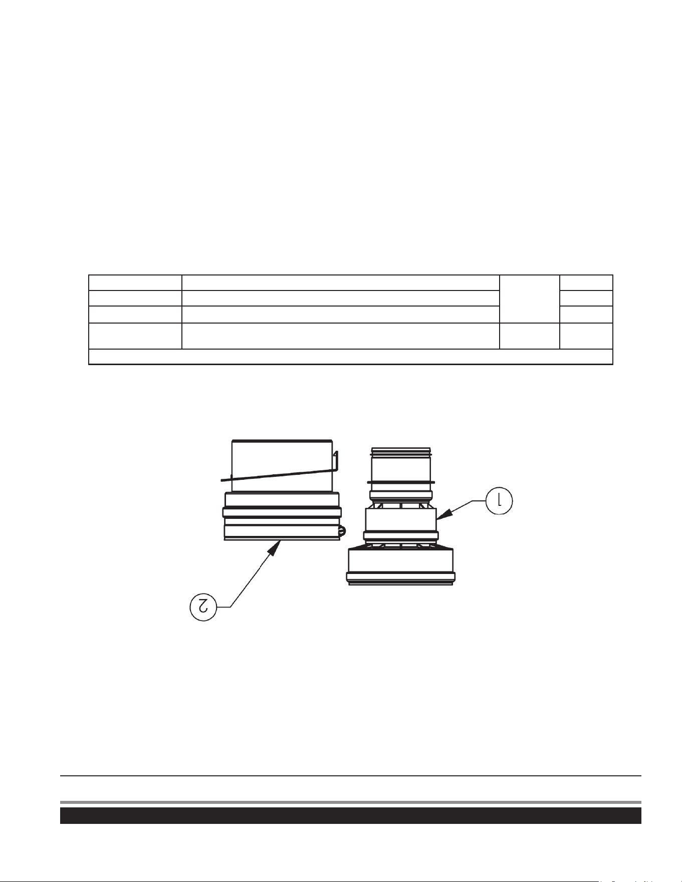
Figure 2. PVC COMMON VENT KIT (300 TO 500 MODELS) (ONE KIT NEEDED FOR EACH HEATER)
Table 2. PVC COMMON VENT KIT PARTS LIST (300 TO 500 MODELS)
Item
No.
Kit
No.
Description
Kit
Supplied
1
100223775
BACKFLOW PREVENTER, 300-500, DURAVENT 1
2 VENT ADAPTER, 300-500, SS, DURAVENT 1
1
2
3
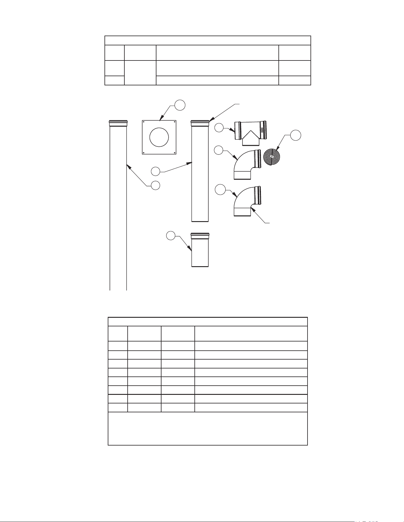
Figure 3. Additional Parts Required - PVC ( FOR US ONLY)
Table 3. FIELD SUPPLIED PARTS - PVC (FOR US ONLY)
Item
No.
Kit
No.
Description
Additional
Required
1 100110441 PLATE,WALL COVER,0.052”,GALV,STEEL 4
2 100226846 VENT SCREEN COUPLING ASSEMBLY,6” 1
3 100078784 AIR INTAKE TERMINAL 1
6
Table 4. FIELD SUPPLIED PARTS - ULC S636 PVC (FOR CANADA)
Kit
No.
Description
Additional
Required
100110441 PLATE,WALL COVER,0.052”,GALV,STEEL 4
IPEX 196142 (PVC) or
IPEX 197141 (CPVC)
COUPLING FOR VENT OUTLET 1
IPEX 196140 (PVC) or
IPEX 197203 (CPVC)
ELBOW FOR AIR INLET 1
100041999 SCREEN 2
SUPPORTS
You will need enough supports so that you can install one every 3 feet of horizontal run and every 5 feet of vertical run for both
the inlet and vent pipe. Supports may be field supplied metal strapping or equivalent.
CONDENSATE DRAIN
Each water heater must have a separate condensate drain line running to an open drain. Follow the directions in the water heater’s
instruction manual. Do not use a common condensate drain line for multiple heaters.
INSTRUCTIONS
PHYSICAL LAYOUT - GENERAL
This kit may be used as part of a common vent installation of up to 3 120 models or up to 3 of any combination of the models in
the 150 to 250 group or the 300 to 500 group listed in
Models Covered
(page 2) in a direct vent configuration. You may not mix
water heaters from the different groups. Check local code requirements regarding common venting of plastic pipe. In Canada, all
plastic pipe must be listed to
ULC S636
.
NOTE: Do not use these parts to combine these water heaters with any other heater or gas appliance.
This kit is meant to common vent water heaters that are physically close to each other and facing the same direction. Additional
limits of this kit are:
• All heaters are on the same floor.
• Through the wall vent and air inlet terminations.
• All heaters are in the same room (pressure zone).
• No change to the system layout, as shown in
Figure 4
(page 7), except as explained in these instructions.
• The adapters shown in
Figure 1
(page 4)
and
Figure 2
(page 5)
must not be modified.
7
The system layout must be planned to minimize the linear length and number of fittings in the system. The kit is meant to
accommodate heaters that maintain the recommended 24” clearance between the water heaters, (52” on center for the 120 to 250
models, 57” on center for the 300 to 500 models, and 66” on center for the BTHL and SUFL models). Consult the water heater’s
installation instructions for proper clearances for service. Consult the water heater’s instruction manual and see
Figure 6
(page
9)
for requirements for locating the air intake and vent terminals.
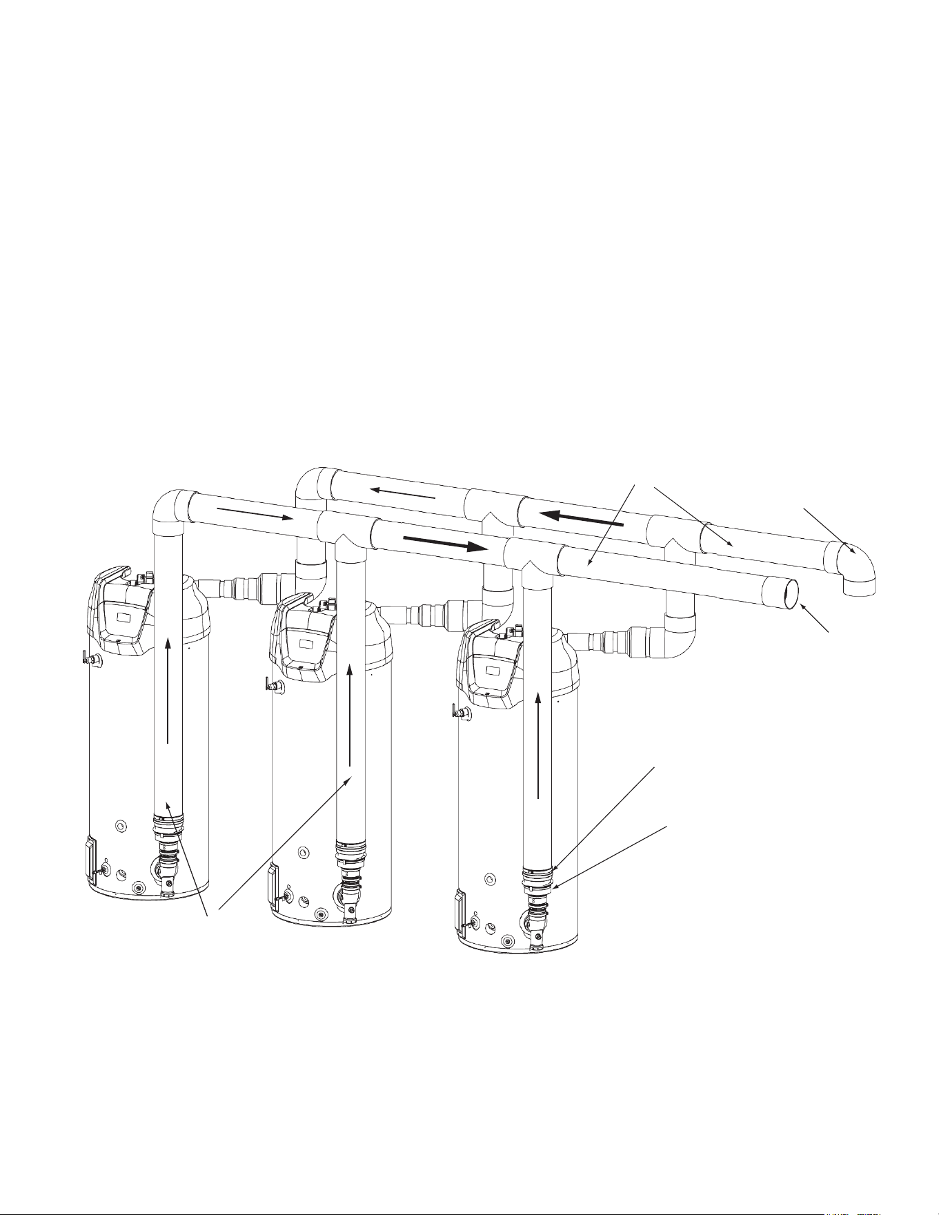
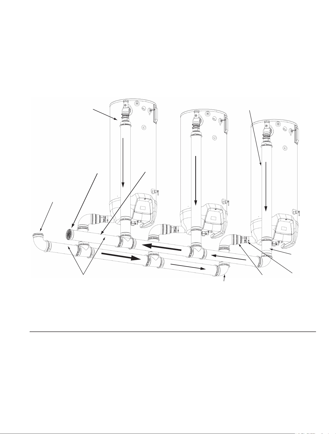
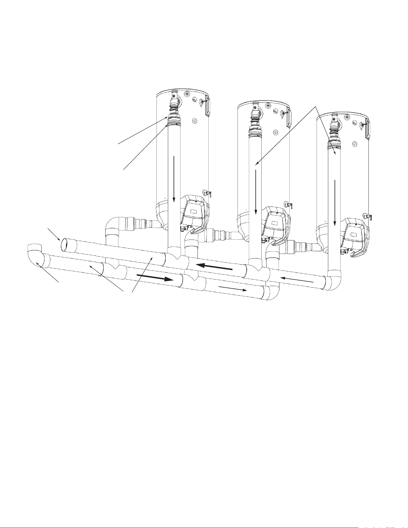
The common vent is the section of the vent and air inlet piping where the gases from all of the heaters flow together, See
Figure
4
. The maximum equivalent length straight pipe and elbows of the common sections is 50 feet. The minimum equivalent length
of the common sections is 3 feet. Each 90° elbow is equal to 5 feet and a 45° elbow is equal to 2½ feet. The maximum number
of elbows is three. The air intake terminal (90° elbow) is not included in the equivalent length.
MAXIMUM EQUIVALENT LENGTHS
The maximum equivalent lengths of the system are:
• Common section: 50 feet
• Connector height: 110”
• Heater spacing: 24” clearance (see above)
If it is necessary to modify the connectors or heater spacing, the equivalent length of additional vent connector, heater spacing or
elbows must be deducted from the 50 equivalent feet of the common vent or common air intake sections.
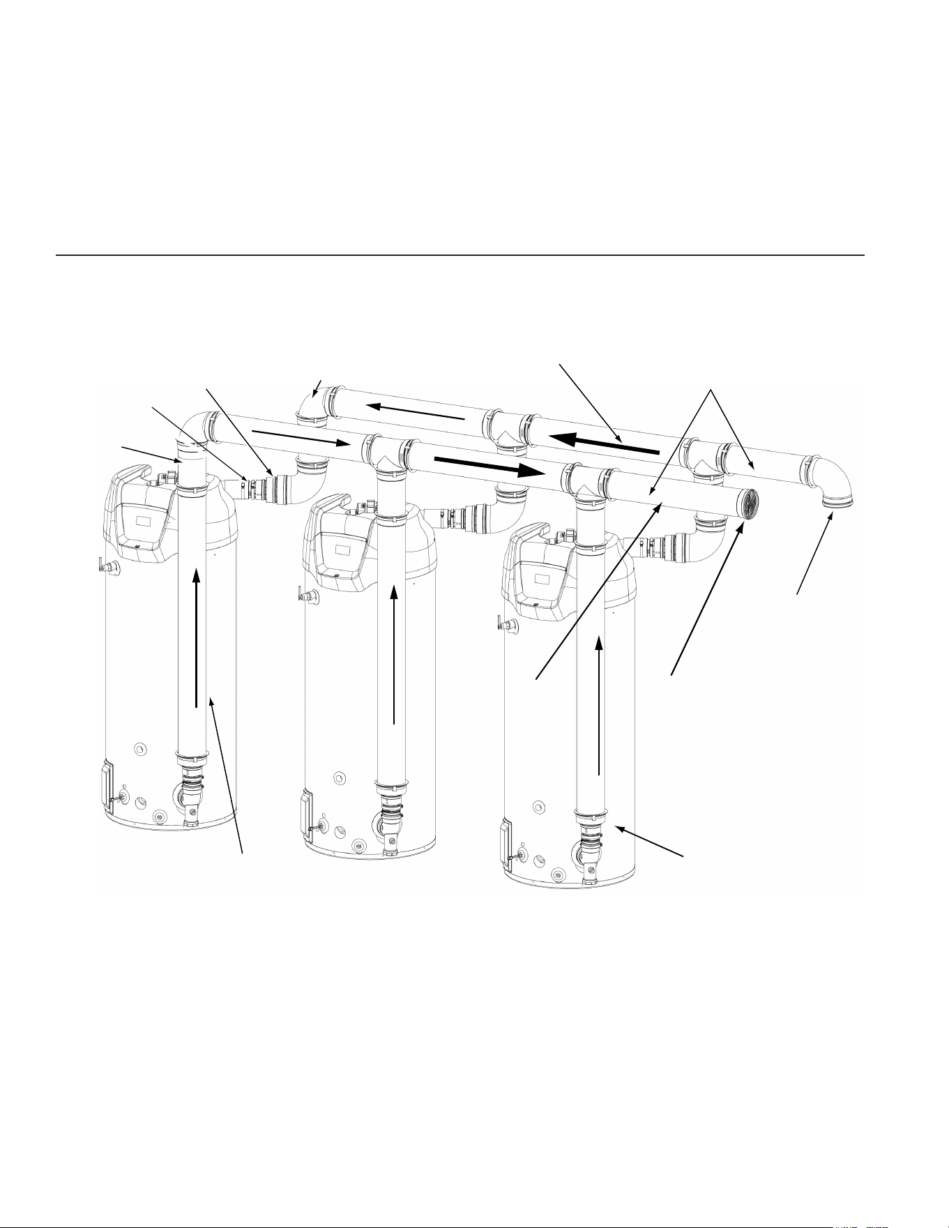
COMMON VENTING
AIR INTAKE TERMINAL
(FIELD SUPPLIED PARTS,
SEE TABLE 3 OR 4)
6"Ø VENT SCREEN
COUPLING ASSEMBLY
(FIELD SUPPLIED PAR
TS,
SEE TABLE 3 OR 4)
VENT ADAPTER PP/PVC, STAINLESS DURAVENT
(KIT SUPPLIED PARTS) (REFER TO TABLES 1 & 2)
VENT ADAPTER, OUTLET 6", PP, DURAVENT
(KIT SUPPLIED PARTS) (SEE TABLES 1 & 2)
INDIVIDUAL VENT
CONNECTOR
Figure 4. Definition of System Sections - PVC
8
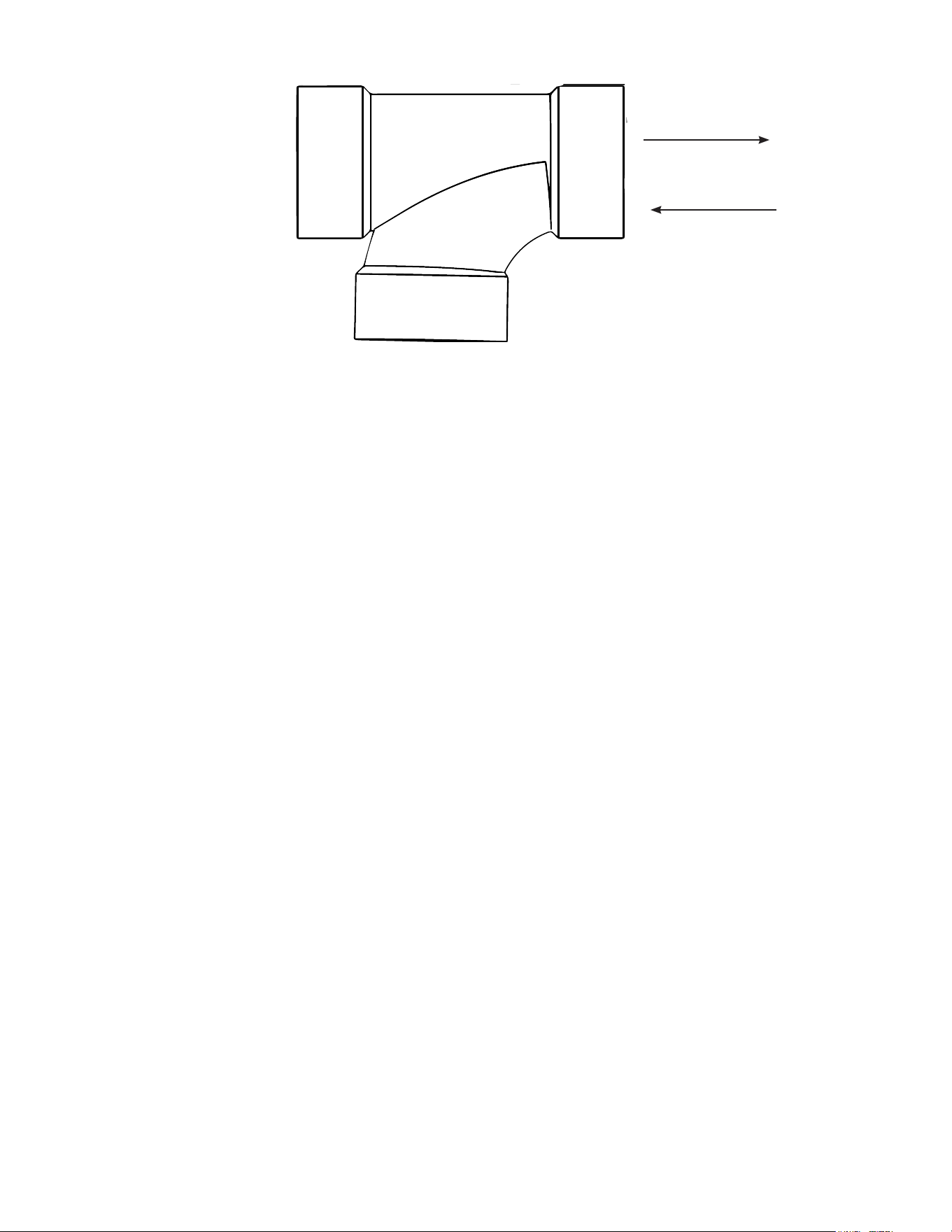
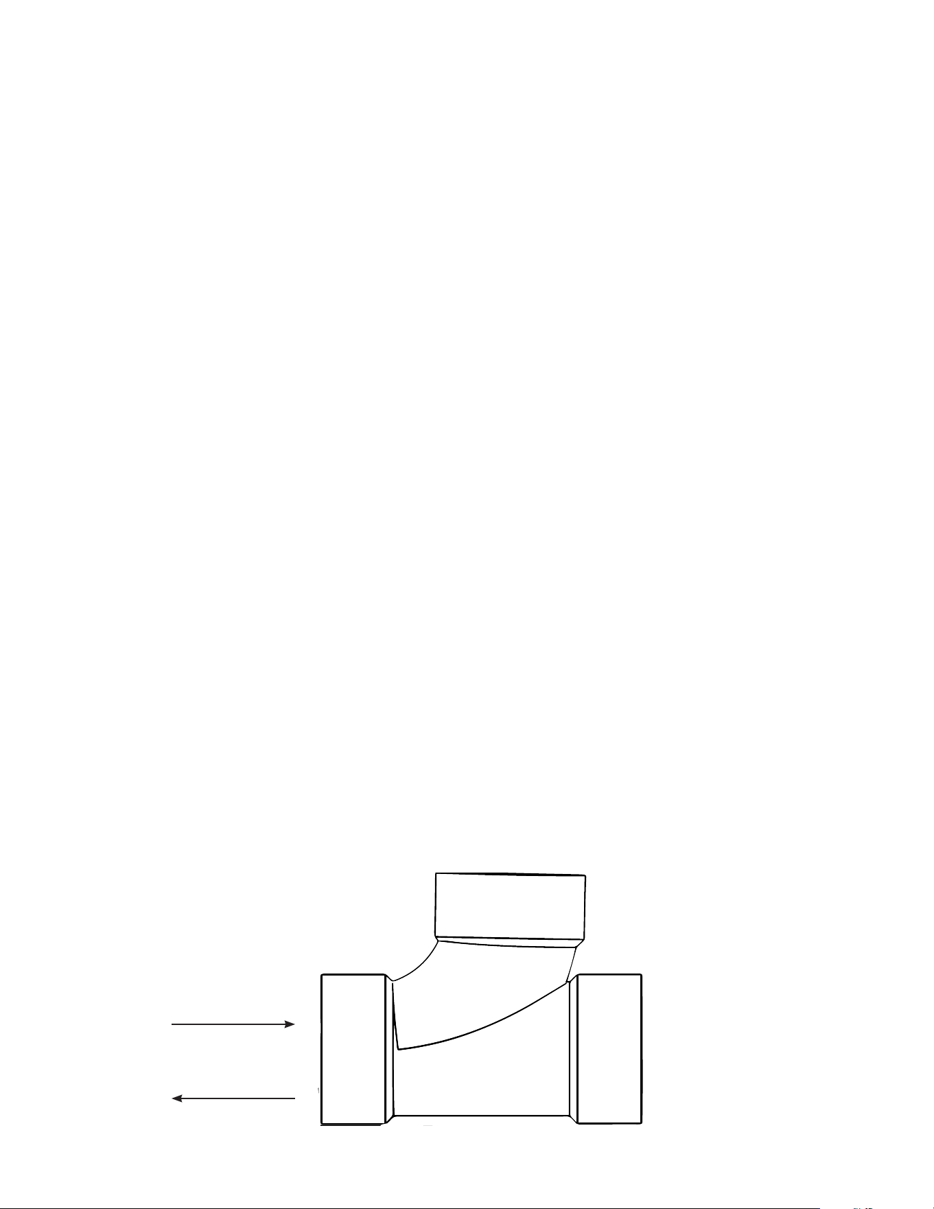
Figure 5. Sanitary TEE
Figure 4
shows the system constructed with straight tees. However, you can use also use sanitary tees, shown in
Figure 5,
as an
acceptable substitute, provided they are arranged so that the flows are in the directions indicated in
Figure 5
.
The individual vent connectors attach the heaters to the common vent. The exhaust vent connectors are attached to the water
heater with the parts in the kit. The air inlet connectors are attached with PVC reducing fittings to the heater’s PVC coupling. As
shown in
Figure 4
, the individual vent connectors consist of vertical and horizontal sections that connect the heater outlets to the
common vent. Using different lengths of pipes, the height of the horizontal sections may be adjusted to be from 80” to 110” from
the bottom of the heater to the center-line of the horizontal section. The combustion air and exhaust vent sides of the system may
be different heights, but each must meet the 80” to 110” height requirement.
SUPPORT
DO NOT SUPPORT WEIGHT OF VENT SYSTEM ON THE HEATER
. Supports must be installed every 3 feet of horizontal run and
5 feet of vertical run for both the inlet and vent pipe. Supports may be made of field supplied metal strapping or equivalent. The
common vent outlet piping must be sloped upwards toward the vent terminal at least 1/4” per foot.
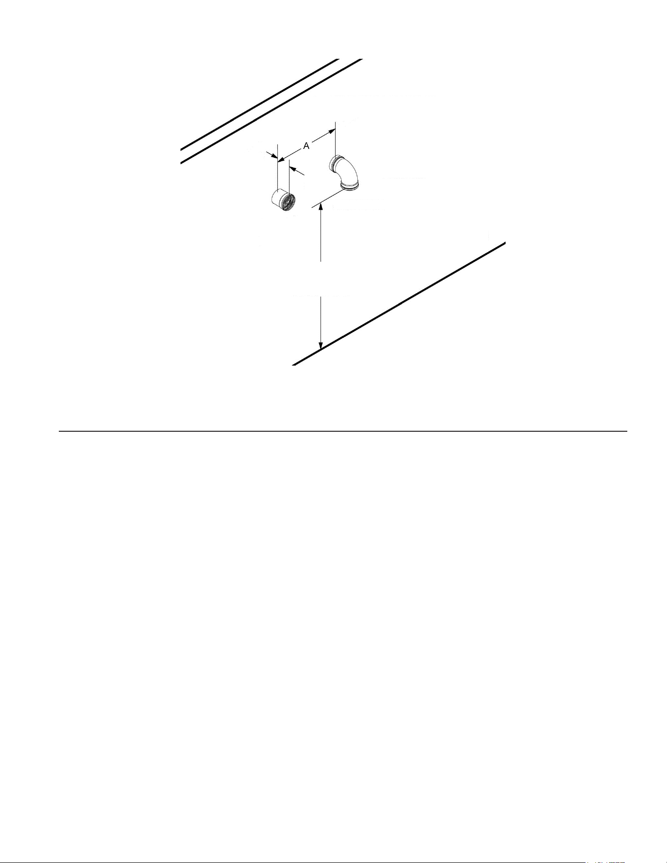
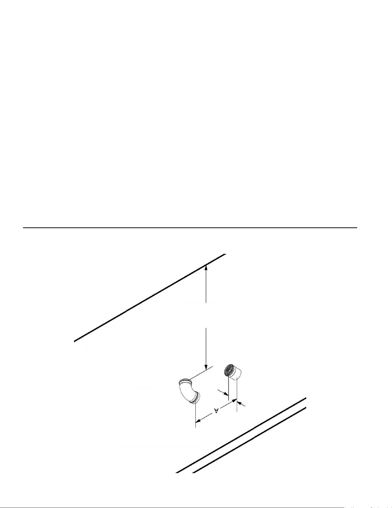
TERMINATIONS
See
Figure 6
(page 9) for location requirements of horizontal vent and intake terminations. You must use the terminations found
in the additional required parts list. The air inlet terminal is a 90° elbow pointing down and the vent outlet is the end of a straight
pipe section, facing horizontally.
Vent Gas Direction
Combustion Air Direction
9
AIR INTAKE
A =
24” MINIMUM INCREASE
,
TO 40” INCHES IN COLD CLIMATES
6” MAX
VENT IN
LEFT
POSITION
12” ABOVE GRADE
OR MAXIMUM EXPECTED
SNOW LEVEL
Figure 6. Wall Terminations
ASSEMBLY
All joints that are PVC to PVC should be attached using approved solvent glue. See the water heater’s Instruction Manual for
additional details. Start the assembly at the wall termination and proceed towards the middle of the common system. Next, start
assembly at the appliances. This will allow small adjustments near the tees over the heaters.
Wall Penetration - The general instructions for penetrating the side wall are found in the Side Wall Terminations section of the
water heater’s instruction manual. The common vent system may not be used with the concentric or low profile vent terminals
as described in the instruction manual supplied with the water heater.
For each penetration, cut a 7” diameter hole through the structure. First, attach the final terminations for the exhaust outlet and
air intake to their final, straight pipes. Outside the building, insert the last straight pipe sections through the wall plates and then,
through the penetration. Run a bead of field-supplied silicone sealant around the wall plate and press it in place. Inside the building,
place a second wall plate over each of the pipes and seal the plates to the wall with silicone sealant. After the vent system is
completely set up, finish the penetrations by sealing the gap between the pipe and wall plates with a bead of silicone sealant.
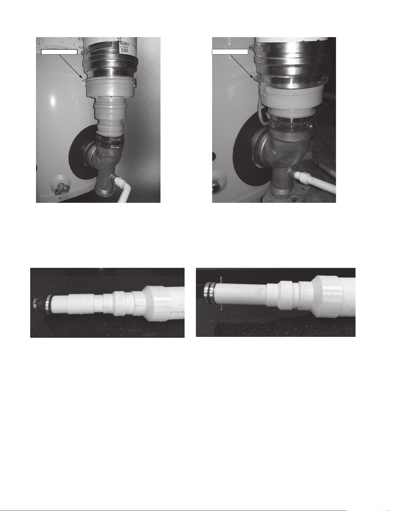
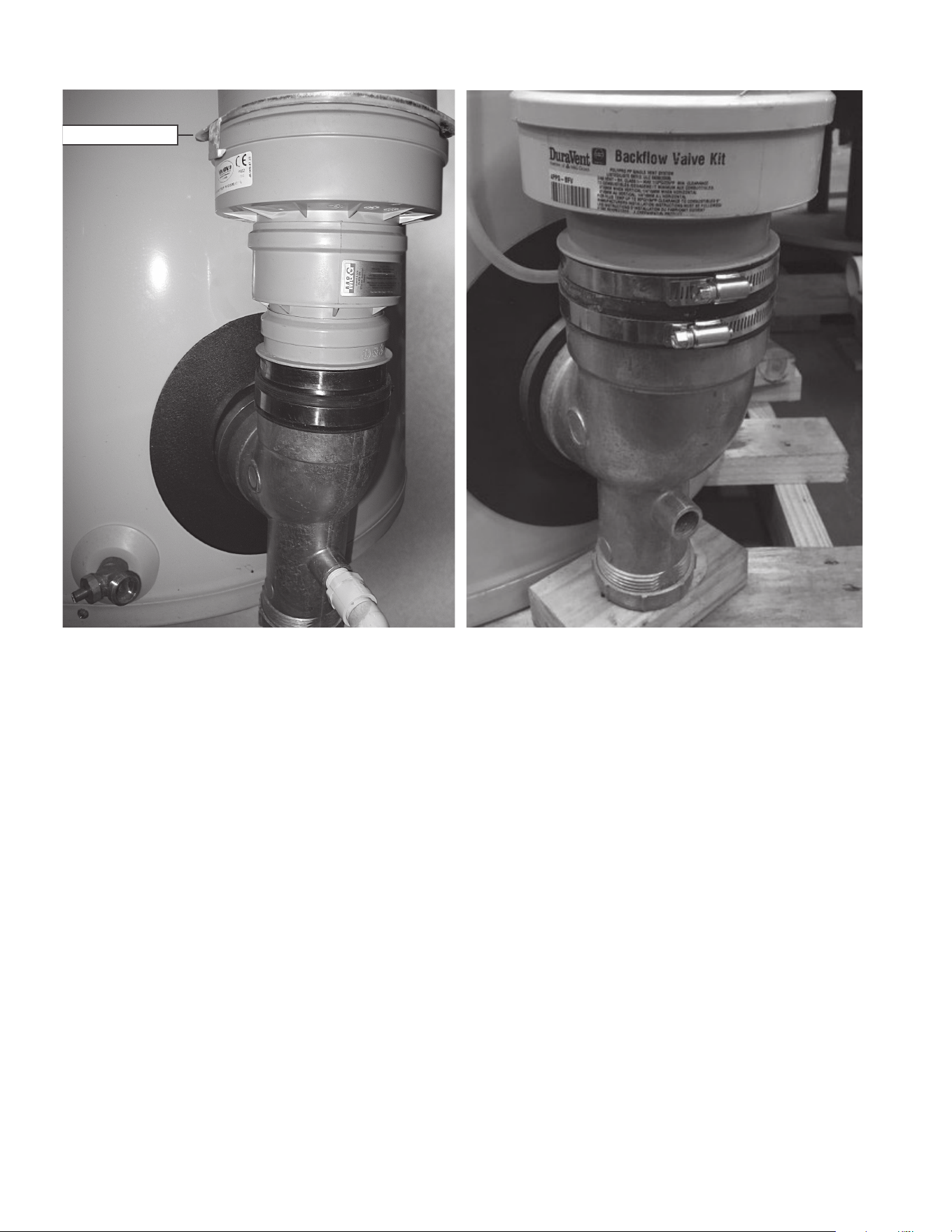
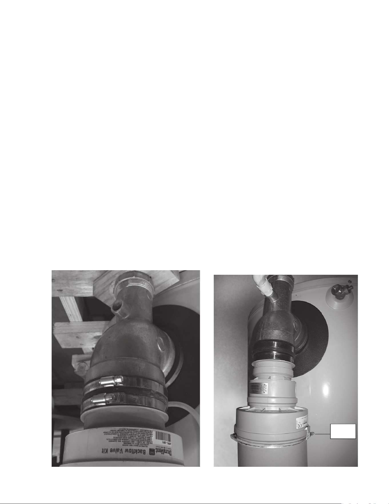
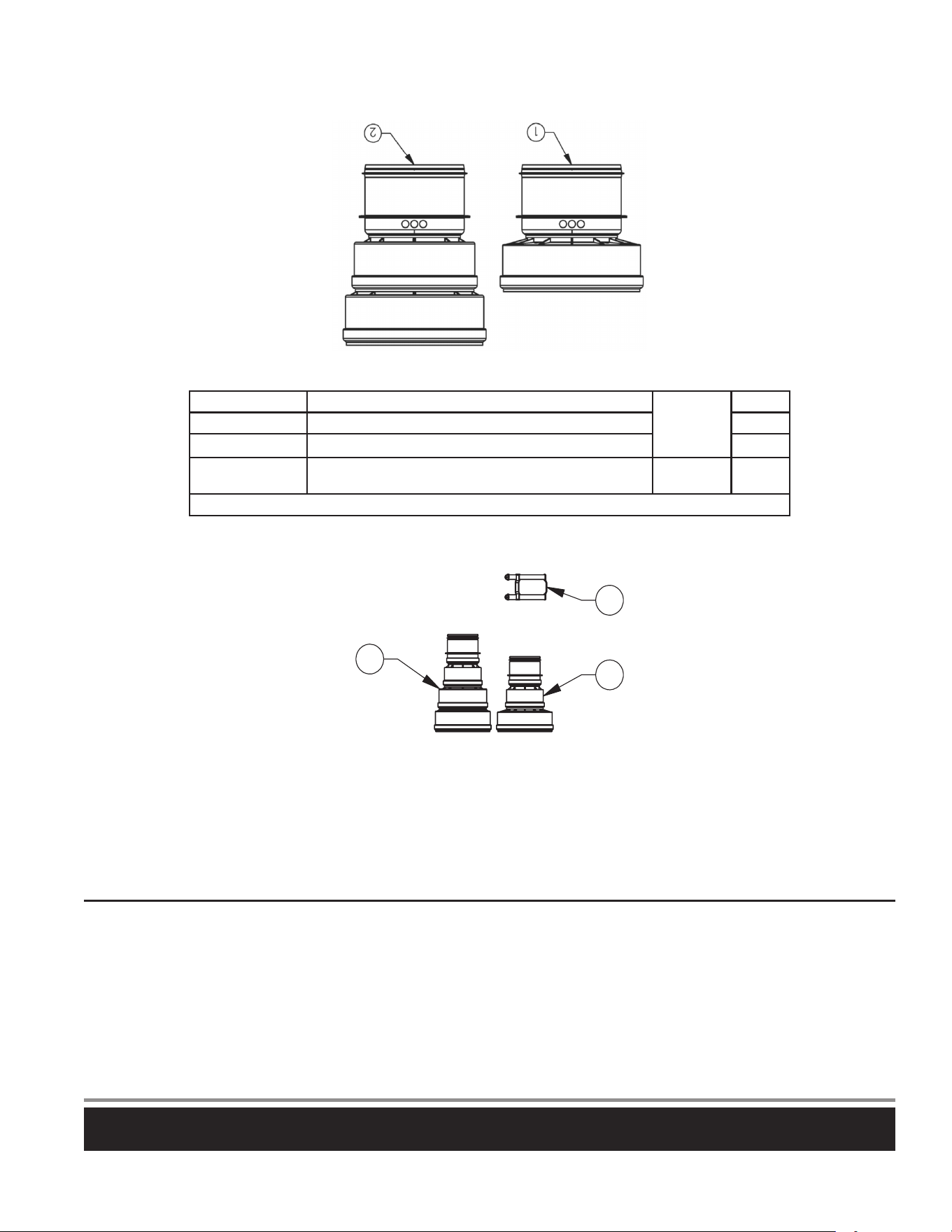
VENT
The exhaust vent is connected to the heater by two adapters. The vent outlet adapter/ backflow preventer is
connected to the aluminum exhaust vent elbow by inserting the male end of the vent outlet adapter into the outlet and securing it
with the rubber boot and hose clamps (supplied with the water heater as shown in
Figure 7
). Next, the Polypropylene/ PVC adapter
is inserted into the outlet of the backflow preventer and secured with the attached locking ring. After that, the remainder of the
exhaust vent side of the common system is composed of field-supplied
Schedule-40
PVC pipe and fittings.
Straight pipe to tee - Use field-supplied straight pipe sections to reach the horizontal part of the system that runs above the heaters.
The total height from the bottom of the heater to the center line of the horizontal must be from 80” to 110”.
10
Locking Ring
Locking Ring
120 - 250 MODELS 300 - 500 MODELS
Figure 7. Outlet Vent Adapter to PVC
INLET AIR SIDE
Attaching to the inlet - The water heater’s air inlet is either a 3” or 4” PVC fitting (
Figure 8)
. For the 120 to 250 models, attach a 3”
to 4” reducing adapter and then, a 4” to 6” reducing adapter to begin the 6” vent connector. The 300 to 500 models require only
a 4” to 6” reducing adapter. A 90° elbow is then attached to turn the connector vertical, towards the remainder of the system.
120 - 250 MODELS
300 - 500 MODELS
Figure 8. PVC AIR INLET
Straight pipe to tee - A straight pipe section is used to run from the elbow to the bottom of the tee. The length may be adjusted so
that the height to the center line of the horizontal run is 80” to 110” from the base of the heater. A straight section is not required
– you may insert the base of the tee into the female end of the elbow.

11
COMMON SECTIONS
The common sections are the pipes that carry the vent gas or intake air to and from the outside. Each pipe must extend from the
tee over the heaters to the outside/ outdoors etc. It is preferred to run the air and vent sections next to each other, over a similar
path as shown in
Figure 4
(page 7). However, differences may be needed in the field. The requirements for both the air intake
and vent common sections are:
• The equivalent length of straight pipe and elbows of each common section will be limited to between 3 feet and 50 feet. Each
90° elbow is equivalent to 5 feet pipe and a 45° elbow is equivalent to 2½ feet of pipe. The maximum number of elbows is
three. The terminal elbows are not considered in calculating maximum or minimum equivalent lengths;
• Each common section may include vertical sections, but the final terminations must be horizontal through the wall. Vertical
section lengths must be included in the total equivalent length.
• The horizontal vent section must be sloped upward at least 1/4” per foot towards the vent terminal and
• Each section must be supported as detailed in the above procedure.
TERMINATIONS
The placement of the vent and air terminals must follow the guidelines for terminal location found in the water heater’s Instruction
Manual. All required clearances to building features are the same as found in the water heater’s Instruction Manual. The combustion
vent terminal is a coupling with a screen that finishes the end of the pipe. The air inlet terminal must use the 90° elbow pointed
down as shown in
Figure 6
(page 9). Clearances to the ground and to anticipated snow level must be as shown in
Figure 6
. The
ends of both terminals must be protected with the bird screens supplied with the terminations.
12
POLYPROPYLENE COMMON VENT KIT INSTRUCTIONS POLYPROPYLENE COMMON VENT KIT INSTRUCTIONS
(100227395 OR 100223774) (100227395 OR 100223774)
This kit instruction is a supplement to the Instruction Manual that is supplied with the water heater. The multiple heater installation must
satisfy all the requirements of the Instruction Manual as well as the requirements of this kit instruction. The installer may also consult
with installation instructions from the vent manufacturer. In the event of any conflict between the documents, these instructions take
precedence. The kit is meant to accommodate heaters that maintain the recommended 24” clearance between the water heaters,
(52” on center for the 120 to 250 models, 57” on center for the 300 to 500 models, and 66” on center for the BTHL and SUFL models).
The heaters listed previously may also be common vented using a Polypropylene system manufactured by M&G Duravent. This is a
system listed to
UL 1738
and
ULC S636
and may be required in some localities.
POLYPROPYLENE PARTS LIST
Each kit contains the adapters needed to connect the vent and air intake system to one heater. Additional parts are needed to create
the connectors, common sections and vent terminations. A list of additional parts is included below for your convenience.
For example, to install a common vent for two heaters requires two common vent kits shown in
Figure 9
, the additional parts listed in
Table 7
, and the necessary polypropylene parts needed to extend the pipe systems between the heaters and the terminations.
2
1
3
Figure 9. Polypropylene Common Vent Kit
(120 - 250 Models) (One Kit Needed for Each Heater)
Table 5. POLYPROPYLENE COMMON VENT KIT (120 - 250 MODELS)
Item
No.
Part
No.
Description
Kit
Supplied
1
100227395
VENT ADAPTER,OUTLET,6”,PP,DURAVENT 1
2 VENT ADAPTER,INLET,6”,PP,DURAVENT 1
3 VENT ADAPTER CONNECTOR,DURAVENT 1
Figure 10. POLYPROPYLENE COMMON VENT KIT (300 - 500 MODELS) (ONE KIT NEEDED FOR EACH HEATER)
13
Table 6. POLYPROPYLENE COMMON VENT KIT (300 -500 MODELS)
Item
No.
Part
No.
Description
Kit
Supplied
1
100223774
BACK-FLOW PREVENTER, 300-500, DU-
RAVENT
1
2 APPLIANCE-INCREASER, 300-500, DURAVENT 1
1
2
4
5
7
3
UV RESISTANT
(BLACK)
UV RESISTANT
(BLACK)
8
6
Figure 11. ADDITIONAL REQUIRED PARTS - POLYPROPYLENE
Table 7. ADDITIONAL REQUIRED PARTS - POLYPROPYLENE Parts List
Item
No.
Part No.
Duravent
Stock No.
Description
1
N/A 810009776
VENT PIPE,6”,72”,PP,DURAVENT
2 N/A 810009774 VENT PIPE,6”,36”,PP,UV,DURAVENT
3 N/A 810009772 VENT PIPE,6”,12”,PP,DURAVENT
4 N/A 810009787 VENT TEE W/CAP,90,6”,PP,DURAVENT
5 N/A 810009783 ELBOW,90,6”,PP,UV,DURAVENT
6 N/A 810004276 BIRD SCREEN,6”,DURAVENT
7 N/A 810009782 ELBOW,90,6”,PP,DURAVENT
8 100110441 N/A PLATE,WALL COVER,0.052”,GALV,STEEL
Notes:
1. ITEMS 1 THRU 7 ARE FIELD SUPPLIED ONLY
2. LOCKING RINGS ARE PREINSTALLED ON PIPES, TEES, AND ELBOWS
14
SUPPORTS
You will need enough supports so that you can install one every 3 feet of horizontal run and every 5 feet of vertical run for both
the inlet and vent pipe. Supports may be field supplied metal strapping or equivalent.
CONDENSATE DRAIN
Each water heater must have a separate condensate drain line running to an open drain. Follow the directions in the water heater’s
Instruction Manual. Do not use a common condensate drain line for multiple heaters.
INSTRUCTIONS
PHYSICAL LAYOUT - GENERAL
The requirements for the layout of the Polypropylene common vent system, required lengths and terminal locations are the same
as for the PVC vent. The overall layout is shown in
Figure 12
. Consult the previous instructions for additional requirements.
INDIVIDUAL VENT
CONNECTOR
6"Ø ELBOW
(FIELD SUPPLIED
PARTS)
INLET
VENT ADAPTER
(KIT SUPPLIED PARTS)
(SEE TABLES 4 & 5)
ADAPTER
CONNECTOR
(KIT SUPPLIED
PARTS, SEE
TABLES 4 & 5)
6 "Ø PIPE/ 12”
(FIELD SUPPLIED
PARTS)
6"Ø ELBOW UV RESISTANT
+
6"Ø BIRD SCREEN
(FIELD SUPPLIED
PARTS)
6"Ø BIRD SCREEN
(FIELD SUPPLIED
PARTS)
6"Ø PIPE
36" UV RESISTANT
(FIELD SUPPLIED
PARTS)
TERMINAL SECTIONS
(UV RESISTANT)
COMMON VENTING
OUTLET VENT ADAPTER
(KIT SUPPLIED PARTS)
(SEE TABLES 4 & 5)
Figure 12. Definition of System Sections - Polypropylene
NOTE: In both the air inlet and vent outlet sides, the female end of the pipe or fitting is always towards the terminations.
The general instructions for penetrating the side wall are found in the Side Wall Terminations sections of the water heater’s Instruction
Manual. The common vent system may not be used with concentric or low profile vent terminals. All pipe and terminations that
are outside the structure should be UV protected (black) parts.
SUPPORT
DO NOT SUPPORT WEIGHT OF VENT SYSTEM ON THE HEATER
. Supports must be installed every 3 feet of horizontal run and
5 feet of vertical run for both the inlet and vent pipe. Supports may be made of field supplied metal strapping or equivalent. The
common vent outlet piping must be sloped upwards toward the vent terminal at least 1/4” per foot.

15
TERMINATIONS
See
Figure 6
(page 9) for location requirements of horizontal vent and intake terminations. You must use the terminations found
in the additional required parts list. The air inlet terminal is a 90° elbow pointing down and the vent outlet is the end of a straight
pipe section, facing horizontally.
ASSEMBLY
For each penetration, cut a 7” diameter hole through the structure. First, attach the final termination for the air intake to its final
straight pipe. Outside the building, insert the male end of the last straight pipe section through the wall plate and then, through
the penetration. This last section should be the UV protected pipe. Run a bead of field-supplied silicone sealant around the wall
plate and press it in place. Inside the building, place a second wall plate over the male end and seal the plate to the wall with
silicone sealant. After the vent system is completely set up, finish the penetration by sealing the gap between the pipe and wall
plates with a bead of silicone sealant. Remove the rubber gasket at the end of the inlet and outlet and insert the bird screen into
the groove that is now available.
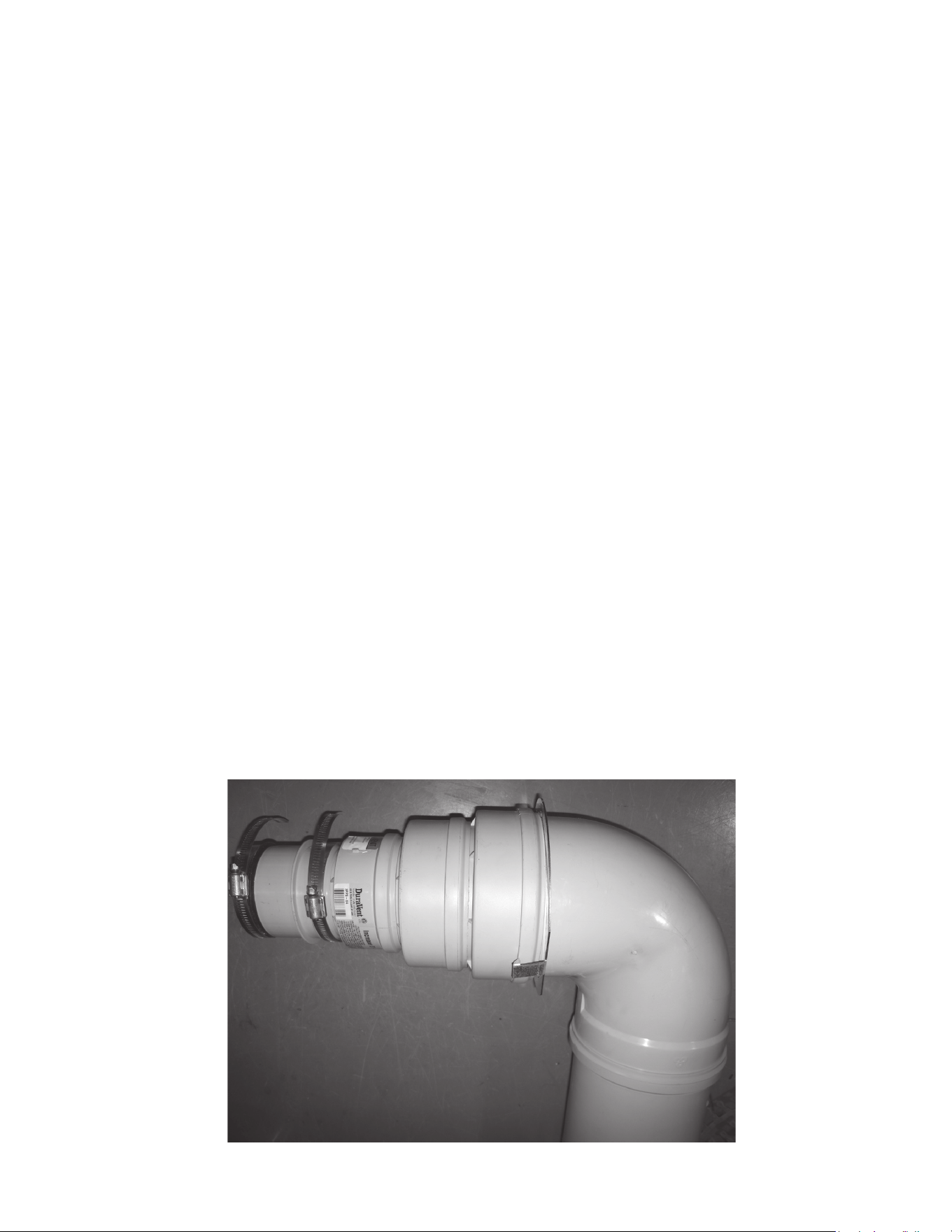
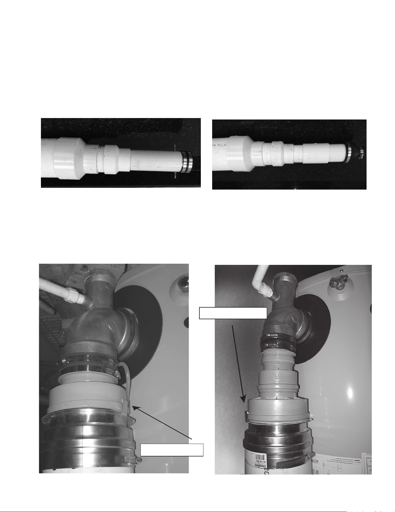
VENT
The vent adapter and back-flow preventer (
Figure 13
) is connected to the aluminum heater outlet and condensate trap by inserting
the male end of the vent outlet adapter into the outlet and securing it with the rubber boot and hose clamps (supplied with the
water heater).
Straight pipe to tee - Use field-supplied straight vent sections to reach the horizontal part of the system that runs above the heaters
Note that the flow in a polypropylene vent pipe is always out of the female end. The total height from the bottom of the heater to
the center line of the horizontal must be from 80” to 110”.
16
LOCKING RING
120-250 Models 300-500 Models
Figure 13. Outlet Vent adapter to Polypropylene
INLET AIR SIDE
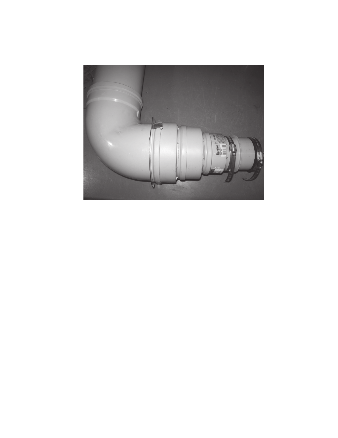
Adapter to inlet - The male end of the air inlet adapter (
Figure 14)
is inserted into the water heater air inlet (a PVC fitting). It is held
in place with the connector adapter supplied in this kit. A 90° elbow is inserted into the female end adapter to turn the system in
a vertical direction.
Straight pipe to tee - A straight pipe section is used to run from the elbow to the bottom of the tee. The length may be adjusted so
that the height to the center line of the horizontal run is 80” to 110” from the base of the heater. A straight section is not required
– you may insert the base of the tee into the female end of the elbow.
17
Figure 14. AIR INLET ADAPTER
COMMON SECTIONS
The common sections are the pipes that carry the vent gas or intake air from multiple units to and from the outside. Each pipe
must extend from the tee over the heaters to the outside/ outdoors etc. It is preferred to run the air and vent sections next to each
other, over a similar path as shown in
Figure 12
(page 14). However, differences may be needed in the field. The requirements
for both the air intake and vent common sections are:
• The equivalent length of straight pipe and elbows of each common section will be limited to between 3 feet and 50 feet. Each
90° elbow is equivalent to 5 feet pipe and a 45° elbow is equivalent to 2½ feet of pipe. The maximum number of elbows is
three. The terminal elbows are not considered in calculating maximum or minimum equivalent lengths.
• Each common section may include vertical sections, but the final terminations must be horizontal through the wall. Vertical
section lengths must be included in the total equivalent length.
• The horizontal vent section must be sloped upward at least 1/4” per foot towards the vent terminal.
• Each section must be supported as detailed in the above procedure.
TERMINATIONS
The placement of the vent and air terminals must follow the guidelines for terminal location found in the water heater’s Instruction
Manual. All required clearances to building features are the same as found in the water heater’s Instruction Manual. The combustion
vent terminal is a coupling with a screen that finishes the end of the pipe. The air inlet terminal must use the 90° elbow pointed
down as shown in
Figure 6
(page 9). Clearances to the ground and to anticipated snow level must be as shown in
Figure 6
. The
ends of both terminals must be protected with the bird screens supplied with the terminations.

18
NOTESNOTES

19
NOTESNOTES

20
For additional information contact:
1-800-527-1953
www.hotwater.com

20
Pour de plus amples informations, contacter:
1-800-527-1953
www.hotwater.com

19
NOTESNOTES

18
NOTESNOTES
17
Figure 14. ADAPTATEUR ENTRÉE D’AIR
SECTIONS COMMUNES
Les sections communes sont des tuyaux qui transporte le gaz d’évent ou l’air d’entrée vers ou de l’extérieur. Chaque tuyau doit
s’étendre du té par-dessus les chauffe-eau vers l’extérieur / dehors, etc. Il est préférable de faire passer les sections d’air et
d’évacuation l’une à côté de l’autre, par-dessus un chemin similaire à celui illustré sur la Figure 1. Cependant, les différences
seront peut-être nécessaires sur place. Les exigences pour les sections communes d’entrée d’air et d’évent sont:
• La longueur équivalente du tuyau droit et les coudes de chacune des sections communes sera limitée entre 0,9 m et 15,2 m
(3 pi et 50 pi). Chaque coude de 90° correspond à 1,5 m (5 pi) et un coude de 45° correspond à 0,75 m (2,5 pi) de tuyau. Trois
est le nombre maximal de coudes. Il n’est pas tenu compte des coudes de bouche lors du calcul des longueurs équivalentes
maximales ou minimales.
• Chaque section commune peut inclure des sections verticales, mais les bouches finales doivent être à travers le mur. Les
longueurs de section verticales doivent être incluses dans la longueur équivalente totale.
• La section d’évent horizontal doit être inclinée vers le haut d’au-moins 21 mm/m (0,25 po/pi) vers la bouche d’évent.
• Chaque section doit être supportée comme détaillé dans la procédure ci-dessus.
BOUCHES
Le positionnement des bouches d’évacuation et d’air doit suivre les directives pour l’emplacement de bouche qui se trouvent dans
le manuel d’instruction du chauffe-eau. Tous les dégagements requis pour les caractéristiques de construction sont les mêmes
que ceux trouvés dans le manuel d’instruction du chauffe-eau. La bouche d’évacuation de combustion est un accouplement avec
un écran qui termine l’embout du tuyau. La bouche d’entrée d’air doit utiliser un coude 90° pointé vers le bas comme illustré sur
la
Figure 6
(page 9). Les dégagements au sol et pour anticiper le niveau de neige doivent être comme illustré à la
Figure 6
. Les
embouts des deux bouches doivent être protégés par des écrans à oiseaux fournis avec les bouches.
16
Bague de
verrouillage
120 - 250 MODELS 300 - 500 MODELS
Figure 13. ADAPTATEUR ÉVENT DE SORTIE AU POLYPROPYLÈNE
CÔTÉ ENTRÉE D’AIR
Adaptateur à entrée – L’extrémité mâle de l’adaptateur d’entrée d’air (voir la
Figure 14
)) est insérée dans l’entrée d’air du chauffe-
eau (un raccord en PVC). Il est tenu en place par un adaptateur de raccord fourni dans cette trousse. Un coude 90° est inséré
dans l’adaptateur à extrémité femelle afin de tourner le système dans le sens vertical.
Tuyau droit à té – Une section de tuyau droit est utilisée pour passer du coude au bas du té. La longueur peut être ajustée afin
que la hauteur à la ligne centrale de l’acheminement horizontal soit de 2032 mm à 2794 mm (80 po à 110 po) depuis la base du
chauffe-eau. Une section droite n’est pas requise – vous pouvez insérer la base du té dans l’extrémité femelle du coude.

15
Les instructions générales concernant la pénétration de murs figurent dans les sections sur les évacuations murales du manuel
d’instruction du chauffe-eau. Le système à évacuation commune n’est pas compatible avec les bouches d’évacuation concentriques
ou compactes. Toutes les conduites et bouches d’extrémité placées à l’extérieur du bâtiment doivent être protégées contre les
UV (noires).
SUPPORT
NE PAS FAIRE REPOSER LE POIDS DU SYSTÈME D’ÉVACUATION SUR LE CHAUFFE-EAU
. Des supports doivent être prévus
tous les 0,9 m (3 pi) pour les portions horizontales et tous les 1,5 m (5 pi) pour les portions verticales de tuyaux d’entrée et
d’évacuation. Les supports (non fournis) peuvent être en bande perforée métallique ou autre moyen équivalent. La tuyauterie
de sortie d’évacuation commune doit être inclinée vers le haut en direction de la bouche d’évacuation à raison d’au moins 2 cm
par mètre (1/4 po par pied).
BOUCHES D’EXTRÉMITÉ
Voir les exigences de placement des bouches d’évacuation et d’admission horizontales à la
Figure 6
(page 9). Utiliser
impérativement des bouches d’extrémités figurant dans la liste des pièces supplémentaires requises. La bouche d’admission
d’air est est un coude de 90° orienté vers le bas et la sortie d’évacuation est l’extrémité d’une portion droite de tuyau placée à
l’horizontale.
ASSEMBLAGE
Les directives générales pour la pénétration du mur latéral se trouvent dans les sections Bouches mur latéral du manuel d’instruction
du chauffe-eau. Le réseau de tuyaux de ventilation commun ne doit pas être utilisé avec des bouches concentriques ou à bas
profil. Tous les tuyaux et toutes les bouches en dehors de la structure doivent être des pièces protégées contre les UV (noires).
Pour chaque pénétration, couper un trou de 178 mm (7 po) de diamètre dans la structure. D’abord, fixer la bouche finale pour
l’entrée d’air à son dernier tuyau droit. Hors du bâtiment, insérer l’embout mâle du dernier tuyau droit dans la plaque murales
puis dans la pénétration. Cette dernière section doit être un tuyau protégé contre les UV. Couler un ruban de silicone fourni sur
place autour de la plaque murale et l’appuyer en place. À l’intérieur du bâtiment, placer une deuxième plaque murale sur l’embout
mâle et sceller les plaques au mur avec du scellant au silicone. Une fois que le réseau de tuyaux de ventilation est entièrement
configuré, terminer la pénétration en fermant l’écart entre le tuyau et les plaques murales avec un ruban de scellant de silicone.
Retirer le joint d’étanchéité en caoutchouc à l’extrémité de l’entrée et de la sortie et insérer l’écran à oiseau dans la rainure qui
est maintenant disponible.
VENTILATION
L’adaptateur de ventilation / sécurité de renvoi (voir Figure 5) est raccordé à la sortie du chauffe-eau en aluminium et le siphon à
condensat en insérant l’extrémité mâle de l’adaptateur de sortie de ventilation dans la sortie et en la fixant avec un manchon en
caoutchouc et des brides à tuyau (fournies avec le chauffe-eau).
Tuyau droit à té – Utiliser des sections d’évent droit fournies sur place pour atteindre la partie horizontale du système qui s’étend
au-dessus des chauffe-eau. Notez que le débit dans un tuyau de ventilation en polypropylène est toujours hors de l’extrémité
femelle. La hauteur totale depuis le bas du chauffe-eau à la ligne centrale de l’horizontal doit être de 2032 mm à 2794 mm (80 po
à 110 po).
14
SUPPORTS
Vous aurez besoin de suffisamment de supports afin de pouvoir installer un tous les 0,9 m (3 pi) d’acheminement horizontal et
tous les 1,5 m (5 pi) d’acheminement vertical pour les deux tuyaux d’entrée et de ventilation. Les supports peuvent être sanglés
en métal ou semblable sur place.
VIDANGE DE CONDENSAT
Chaque chauffe-eau doit avoir une conduite de vidange de condensat séparée acheminée vers un drain ouvert. Suivre les
directives dans le manuel d’instruction du chauffe-eau. Ne pas utiliser une conduite de vidange de condensat commune pour
plusieurs chauffe-eau.
DIRECTIVES
DISPOSITION PHYSIQUE – GÉNÉRALITÉS
Les exigences pour la disposition du réseau de tuyaux de ventilation commun en polypropylène, les longueurs requises et
l’emplacement de la bouche sont les mêmes que pour l’évent en PVC. La disposition générale est illustrée sur la
Figure 12
. Consulter
les directives précédentes pour les exigences supplémentaires.
RACCORD
D’ÉVENT INDIVIDUEL
Ø 6 po COUDE
(FOURNI
SUR PLACE)
ADAPTATEUR
D’ÉVENT D’ENTRÉE
(PIÈCES FOURNIES
DANS LA TROUSSE)
RACCORD
D’ADAPTATEUR
(PIÈCES FOURNIES
DANS LA TROUSSE)
Ø 6 po TUYAU
305 mm (12 po)
(PIÈCES FOURNIES
SUR PLACE)
COUDE RÉSISTANT Ø 6 po +
ÉCRAN À OISEAUX Ø 6 po
(PIÈCES FOURNIES
SUR PLACE)
ÉCRAN À OISEAUX Ø 6 po
(PIÈCES FOURNIES
SUR PLACE)
TUYAU Ø 6 po
914 mm (36 po)
RÉSISTANT AUX UV
(PIÈCES FOURNIES
SUR PLACE)
VENTILATION COMMUNE
ADAPTATEUR
D’ÉVENT DE SORTIE
(PIÈCES FOURNIES
DANS LA TROUSSE)
(VOIR LES TABLES 4 & 5)
Figure 12. DÉFINITION DES SECTIONS DU SYSTÈME - POLYPROPYLÈNE
REMARQUE: Dans les deux côtés d’entrée d’air et de sortie d’évent, l’extrémité femelle du tuyau ou du raccord est toujours vers
les terminaisons.
13
(UNE TROUSSE REQUISE POUR CHAQUE CHAUFFE-EAU)
Table 6. TROUSSE D’ÉVENT COMMUN EN POLYPROPYLÈNE (MODÈLES 300 - 500)
Article
N°
Trousse
N°
Description
FOURNI AVEC LA
TROUSSE
1
100223774
DISPOSITIF ANTI-RETOUR, 300-500, DURAVENT 1
2 AUGMENTATION-APPAREIL, 300-500, DURAVENT 1
1
2
4
5
7
3
RÉSISTANT
AUX UV
(NOIR)
RÉSISTANT
AUX UV
(NOIR)
8
6
Figure 11. AUTRES PIÈCES REQUISES - POLYPROPYLÈNE
Table 7. AUTRES PIÈCES REQUISES - POLYPROPYLÈNE
Article
N°
Trousse N°
Duravant
N°
DE STOCK
Description
1
S/O 810009776
TUYAU DE VENTILATION, 6 PO, 1829 mm (72 PO), PP, DURAVENT
2 S/O 810009774 TUYAU DE VENTILATION, 6 PO, 914 mm (36 PO), UV, DURAVENT
3 S/O 810009772 TUYAU DE VENTILATION, 6 PO, 305 mm (12 PO), PP, DURAVENT
4 S/O 810009787 TÉ D’ÉVENT AVEC CAPUCHON, 90, 6 PO, PP, DURAVENT
5 S/O 810009783 COUDE, 90, 6 PO, UV, DURAVENT
6 S/O 810004276 ÉCRAN À OISEAUX, 6 PO, DURAVENT
7 S/O 810009782 COUDE, 90, 6 PO, UV, DURAVENT
8 100110441 S/O PLAQUE, CACHE MUR, 0,052 PO, GALV, ACIER
REMARQUES:
1. LES ARTICLES 1 À 8 SONT UNIQUEMENT FOURNIS SUR PLACE
2. LES ANNEAUX DE SERRAGE SONT DÉJÀ INSTALLÉS SUR LES TUYAUX,
TÉS ET COUDES
12
TROUSSE D’ÉVENT COMMUN EN POLYPROPYLÈNE INSTRUCTIONS (100227395 OR TROUSSE D’ÉVENT COMMUN EN POLYPROPYLÈNE INSTRUCTIONS (100227395 OR
100223774) 100223774)
Ce mode d’emploi de trousse est un complément au manuel d’instructions fourni avec le chauffe-eau. Une installation à plusieurs
chauffe-eau doit être conforme à toutes les exigences du manuel d’instructions ainsi qu’aux exigences de ce mode d’emploi.
L’installateur peut également consulter les instructions d’installation du fabricant du système d’évacuation. En cas de divergence
entre les documents, veiller à respecter les présentes instructions. Cette trousse est destinée aux chauffe-eau qui maintiennent
le dégagement recommandé de 610 mm (24 po) entre les chauffe-eau (1321 mm [52 po] de centre à centre pour les modèles
120 à 250, 1448 mm [57 po] pour les modèles 300 à 500 et 1676 mm [66 po] pour les modèles BTHL et SUFL).
Les chauffe-eau énumérés auparavant peuvent aussi être ventilés de manière commune par un système en polypropylène fabriqué
par M&G Duravent. C’est un système homologué par
UL 1738
et
ULC S636
, ce qui peut être requis par certaines municipalités.
LISTE DES PIÈCES DE RECHANGE EN POLYPROPYLÈNE
Chaque kit contient les adaptateurs nécessaires pour relier l’évent et le système d’admission d’air à un chauffage. Des pièces
supplémentaires sont nécessaires pour créer les connecteurs, les sections communes et les terminaisons d’évent. Une liste de
pièces supplémentaires est incluse ci-dessous pour votre commodité.
Par exemple, pour installer un évent commun pour deux appareils de chauffage, il faut deux kits d’évent communs représentés
sur la Figure 7, les parties additionnelles énumérées dans le Tableau 6 et les parties de polypropylène nécessaires pour étendre
les systèmes de tuyaux entre les radiateurs et les terminaisons.
2
1
3
Figure 9. TROUSSE D’ÉVENT COMMUN EN POLYPROPYLÈNE (MODÈLES 120 - 250)
(UNE TROUSSE REQUISE POUR CHAQUE CHAUFFE-EAU)
Table 5. TROUSSE D’ÉVENT COMMUN EN POLYPROPYLÈNE (MODÈLES 120 - 250)
Article
N°.
Trousse N° Description
FOURNI AVEC LA
TROUSSE
1
100227395
ADAPTATEUR D’ÉVENT, SORTIE, 6 PO, PP, DURAVENT 1
2 ADAPTATEUR D’ÉVENT, ENTRÉE, 6 PO, PP, DURAVENT 1
3 RACCORD ADAPTATEUR D’ÉVENT, DURAVENT 1
Figure 10. TROUSSE D’ÉVENT COMMUN EN POLYPROPYLÈNE (MODÈLES 300 - 500)

11
SECTIONS COMMUNES
Les sections communes sont des tuyaux qui transporte le gaz d’évent ou l’air d’entrée vers ou de l’extérieur. Chaque tuyau doit
s’étendre du té par-dessus les chauffe-eau vers l’extérieur / dehors, etc. Il est préférable de faire passer les sections d’air et
d’évacuation l’une à côté de l’autre, par-dessus un chemin similaire à celui illustré sur la Figure 1. Cependant, les différences
seront peut-être nécessaires sur place. Les exigences pour les sections communes d’entrée d’air et d’évent sont:
• La longueur équivalente du tuyau droit et les coudes de chacune des sections communes sera limitée entre 0,9 m et 15,2 m
(3 pi et 50 pi). Chaque coude de 90° correspond à 1,5 m (5 pi) et un coude de 45° correspond à 0,75 m (2,5 pi) de tuyau. Trois
est le nombre maximal de coudes. Il n’est pas tenu compte des coudes de bouche lors du calcul des longueurs équivalentes
maximales ou minimales.
• Chaque section commune peut inclure des sections verticales, mais les bouches finales doivent être à travers le mur. Les
longueurs de section verticales doivent être incluses dans la longueur équivalente totale.
• La section d’évent horizontal doit être inclinée vers le haut d’au-moins 21 mm/m (0,25 po/pi) vers la bouche d’évent.
• Chaque section doit être supportée comme détaillé dans la procédure ci-dessus.
BOUCHES
Le positionnement des bouches d’évacuation et d’air doit suivre les directives pour l’emplacement de bouche qui se trouvent dans
le manuel d’instruction du chauffe-eau. Tous les dégagements requis pour les caractéristiques de construction sont les mêmes
que ceux trouvés dans le manuel d’instruction du chauffe-eau. La bouche d’évacuation de combustion est un accouplement avec
un écran qui termine l’embout du tuyau. La bouche d’entrée d’air doit utiliser un coude 90° pointé vers le bas comme illustré sur
la
Figure 6
(page 9). Les dégagements au sol et pour anticiper le niveau de neige doivent être comme illustré à la
Figure 6
. Les
embouts des deux bouches doivent être protégés par des écrans à oiseaux fournis avec les bouches.
10
ANNEAU DE SERRAGE
ANNEAU DE SERRAGE
120 - 250 MODELS 300 - 500 MODELS
Figure 7. Adaptateur de sortie pour PVC
CÔTÉ ENTRÉE D’AIR
Fixation à l’entrée - L’entrée d’air du chauffe-eau est soit un raccord en PVC de 3 “ou 4” (
Figure 8)
. Pour les modèles de 120 à 250,
attachez un adaptateur de réduction de 3 “à 4”, puis un adaptateur de réduction de 4 “à 6” pour commencer le connecteur de
ventilation de 6 “. Les modèles de 300 à 500 ne nécessitent qu’un adaptateur réducteur de 4 “à 6”. Un coude à 90 ° est ensuite
fixé pour tourner le connecteur vertical, vers le reste du système.
120 - 250 MODELS
300 - 500 MODELS
Figure 8. Entrée d’air PVC
Tuyau droit à té – Une section de tuyau droit est utilisée pour passer du coude au bas du té. La longueur peut être ajustée afin
que la hauteur à la ligne centrale de l’acheminement horizontal soit de 2032 mm à 2794 mm (80 po à 110 po) depuis la base du
chauffe-eau. Dans certains cas, il est souhaitable de fournir un moyen pour vidanger l’eau provenant des pluies hors de l’entrée
d’eau. Le drain doit être un raccord de 6 po de diamètre avec un drain à siphon en J, comme détaillé dans le manuel d’instruction
du chauffe-eau. Le drain doit être placé juste avant le té qui joint la section commune aux raccords (hors des chauffe-eau).
9
ENTRÉE D’AIR
A = 610 MM (24 PO) MINIMUM,
AUGMENTER À 1219 MM (48 PO) POUR
LES CLIMATS FROIDS
152 MM
(6 PO)
MAX
ÉVENT EN
POSITION
GAUCHE
305 MM (12 PO) AU-DESSUS DU
NIVEAU DE NEIGE PRÉVU OU
AU MAXIMUM ATTENDU
Figure 6. BOUCHES MURALES
ASSEMBLAGE
Tous les joints qui sont de PVC à PVC doivent être fixés avec de la colle solvant approuvée. Vous reporter au manuel d’instruction
du chauffe-eau pour de plus amples détails. Commencer l’assemblage à la bouche du mur et procéder vers le milieu du système
commun. Ensuite, commencer l’assemblage des appareils. Ceci permet les petits ajustements près des tés sur les chauffe-eau.
Pénétration du mur – Les directives générales pour la pénétration du mur latéral se trouvent dans les sections mur latéral du
manuel d’instruction du chauffe-eau. Le un réseau de tuyaux de ventilation commun ne peut être utilisé avec les bouches d’évent
à profil concentrique ou bas comme décrit dans le manuel d’instruction fourni avec le chauffe-eau.
Pour chaque pénétration, couper un trou de 178 mm (7 po) de diamètre dans la structure. D’abord, fixer les bouches finales pour
la sortie d’échappement et l’entrée d’air à leurs tuyaux droits. Hors du bâtiment, insérer les dernières sections de tuyau droit dans
les plaques murales puis dans la pénétration. Couler un ruban de silicone fourni sur place autour de la plaque murale et l’appuyer
en place. À l’intérieur du bâtiment, placer une deuxième plaque murale sur chacun des tuyaux et sceller les plaques au mur avec
du scellant au silicone. Une fois que le réseau de tuyaux de ventilation est entièrement configuré, terminer les pénétrations en
fermant l’écart entre le tuyau et les plaques murales avec un ruban de scellant de silicone.
VENTILATION
L’évacuation d’air est raccordée au chauffe-eau par deux adaptateurs. L’adaptateur de sortie de ventilation / sécurité de renvoi
est raccordée au coude d’évacuation d’air en aluminium en insérant l’extrémité mâle de l’adaptateur de sortie de ventilation dans
la sortie et en la fixant avec un manchon en caoutchouc et des brides à tuyau (fournie avec le chauffe-eau comme illustré sur la
Figure 3). Enduite, l’adaptateur en polypropylène/PVC est inséré dans la sortie de la sécurité de refoulement et fixé avec l’anneau
de serrage attaché. Ensuite, le reste du côté d’évacuation d’air du système commun est composé de tuyau en PVC
cédule 40
et
de raccords fournis sur le terrain.
Tuyau droit à té – Utiliser des sections de tuyau droit fournies sur place pour atteindre la partie horizontale du système qui s’étend
au-dessus des chauffe-eau. La hauteur totale depuis le bas du chauffe-eau à la ligne centrale de l’horizontal doit être de 2032
mm à 2794 mm (80 po à 110 po).
8
Figure 5. Tee sanitaire
La
Figure 4
montre le système construit avec des tés droits. Cependant, vous pouvez également utiliser des tees hygiéniques,
représentées sur la
Figure 5
comme un substitut acceptable, à condition qu’elles soient disposées de telle sorte que les courants
soient dans les directions indiquées sur
Figure 5
.
Les connecteurs d’évent individuels fixent les chauffe-eau à l’évent commun. Les connecteurs d’évent d’échappement sont fixés
au chauffe-eau avec les pièces de la trousse. Les connecteurs d’entrée d’air sont fixés avec des raccords réducteurs en PVC à
l’accouplement en PVC du chauffe-eau. Comme illustré sur la
Figure 4
les connecteurs d’évent individuel consistent en sections
verticales et horizontales qui se raccordent aux sorties du chauffe-eau à l’évent commun. À l’aide de différentes longueurs de
tuyau, la hauteur des sections horizontales peut être ajustée de 2032 mm à 2794 mm (80 po à 110 po) du bas du chauffe-eau
à la ligne du centre de la section horizontale. Les côtés air de combustion et évent d’échappement du système peuvent être de
différentes hauteurs, mais chacune doit satisfaire à l’exigence à l’égard de la hauteur de 2032 mm à 2794 mm (80 po à 110 po).
SUPPORT
NE PAS FAIRE SUPPORTER LE POIDS DU RÉSEAU DE TUYAUX DE VENTILATION PAR LE CHAUFFE-EAU. Les supports
doivent être installés à tous les 0,9 m (3 pi) de l’acheminement horizontal et 1,5 m (5 pi) de l’acheminement vertical pour le tuyau
d’entrée et de ventilation. Les supports peuvent être fournis en métal ou semblable sur place. La tuyauterie de sortie d’évent
commune doit être inclinées vers le haut vers la bouche d’évent à au moins 21 mm/m (0,25 po/pi).
BOUCHES
Vous reporter à la
Figure 6
(page 9) pour les exigences sur l’emplacement de l’évent horizontal et les bouches d’entrée. Vous
devez utiliser les bouches qui se trouvent dans la liste des pièces supplémentaires requises. La bouche d’entrée d’air est un
coude de 90° pointant vers le bas et la sortie d’évent est l’embout d’une section de tuyau droit, tourné à l’horizontal.
Direction de l’air de combustion
Direction du gaz d’échappement
7
La configuration du système doit être planifiée de façon à minimiser la longueur linéaire et le nombre de raccords dans le circuit.
Cette trousse est destinée aux chauffe-eau qui maintiennent le dégagement recommandé de 610 mm (24 po) entre les chauffe-eau
(1321 mm [52 po] de centre à centre pour les modèles 120 à 250, 1448 mm [57 po] pour les modèles 300 à 500 et 1676 mm
[66 po] pour les modèles BTHL et SUFL). Voir les dégagements requis pour l’entretien dans les instructions d’installation du
chauffe-eau. Dans le manuel d’instructions du chauffe-eau, voir les exigences relatives au et voir les exigences de placement
des bouches d’admission d’air et d’évacuation à la
Figure 6
(page 9)
.
L’évent commun est la section de l’évent et le tuyau d’entrée d’air où les gaz des deux chauffe-eau circulent ensemble, voir la
Figure 4
. Le tuyau droite à longueur équivalente maximale et le coude des sections communes est de 15,2 m (50 pi). La longueur
équivalent minimale des sections communes est de 0,9 m (3 pi). Chaque coude de 90° correspond à 1,5 m (5 pi) et un coude
de 45° correspond à 0,75 m (2,5 pi). Trois est le nombre maximal de coudes. La bouche d’entrée d’air (coude de 90°) n’est pas
inclue dans la longueur équivalente.
LONGUEURS MAXIMALES ÉQUIVALENTES
Les longueurs équivalentes maximales normales du système sont :
• Section commune: 15,2 m (50 pi)
• Hauteur du connecteur : 2794 mm (110 po)
• Espacement du chauffe-eau : Dégagement 610 mm (24 po) (voir ci-dessus).
S’il est nécessaire de modifier les connecteurs ou l’espacement du chauffe-eau : la longueur équivalente du connecteur d’évent
supplémentaire, l’espacement du chauffe-eau ou les coudes doivent être déduits des 15,2 m (50 pi) équivalents de l’évent commun
ou des sections d’entrée d’air communes.
ÉVACUATION COMMUNE
BOUCHE D’ADMISSION D’AIR
(PIÈCES NON FOURNIES,
VOIR TABLE 3 OU 4)
ACCOUPLEMENT D’ÉVACUATION
À GRILLAGE DE Ø 6 PO
(PIÈCES NON FOURNIES,
VOIR TABLE 3 OU 4)
ADAPTATEUR D’ÉVACUATION PP/PVC, ACIER INOXYDABLE, DURAVENT
(PIÈCES FOURNIES AVEC LA TROUSSE)
(VOIR TABLES 1 ET 2)
ADAPTATEUR D’ÉVACUATION, SORTIE 6 PO, PP, DURAVENT
(PIÈCES FOURNIES AVEC LA TROUSSE)
(VOIR TABLES 1 ET 2)
RACCORD D’ÉVACUATION INDIVIDUEL
Figure 4. Définition des sections du système - PVC
6
Table 4. Pièces livrées sur site - ULC S636 PVC (pour le Canada)
Article N°. Trousse N° La description
Autre
Requis
1 100110441 PLAQUE, COUVERCLE DE MUR, 0.052 “, GALV, ACIER 4
2 IPEX 196142 (PVC)
or
IPEX 197141 (CPVC)
COUPLAGE POUR SORTIE VENT 1
3 IPEX 196140 (PVC)
or
IPEX 197203 (CPVC)
COUDE POUR L’ENTRÉE D’AIR 1
4 100041999 Écran 2
SUPPORTS
Vous aurez besoin de suffisamment de supports afin de pouvoir installer un tous les 0,9 m (3 pi) d’acheminement horizontal et
tous les 1,5 m (5 pi) d’acheminement vertical pour les deux tuyaux d’entrée et de ventilation. Les supports peuvent être sanglés
en métal ou semblable sur place.
VIDANGE DE CONDENSAT
Chaque chauffe-eau doit avoir une conduite de vidange de condensat séparée acheminée vers un drain ouvert. Suivre les
directives dans le manuel d’instruction du chauffe-eau. Ne pas utiliser une conduite de vidange de condensat commune pour
plusieurs chauffe-eau.
DIRECTIVES
DISPOSITION PHYSIQUE – GÉNÉRALITÉS
Ce kit peut être utilisé dans le cadre d’une installation d’évacuation commune de jusqu’à trois modèles de 120 ou jusqu’à trois
de n’importe quelle combinaison des modèles du groupe de 150 à 250 ou du groupe de 300 à 500 répertorié dans les
Modèles
qui sont couverts
(page 2)
c
onfiguration d’évacuation directe horizontale. Vérifiez les exigences du code local concernant la
ventilation commune des tuyaux en plastique. Au Canada, tous les tuyaux en plastique doivent être inscrits dans la liste
ULC S636
.
REMARQUE : ne pas utiliser ces pièces pour combiner ces chauffe-eau avec aucun autre chauffe-eau ou appareil au gaz.
Cette trousse est destinée aux chauffe-eau à évent commun qui sont proches physiquement les uns des autres et tournés dans
le même sens. Limites supplémentaires de cette trousse sont :
• Tous les appareils de chauffage à l’étage.
• Évent à travers le mur et terminaisons d’entrée d’air.
• Tous les chauffe-eau dans la même pièce (zone de pression),
• Aucun changement à la disposition du système, comme illustré sur la
Figure 1
(page 4), sauf comme expliqué dans la
section suivante et
• Les adaptateurs illustrés dans la
Figure 1
(page 4)
et la
Figure 2
(page 5)
ne doivent pas être modifiés.
5
Figure 2. TROUSSE D’ÉVENT COMMUN EN PVC (MODÈLES 300 À 500)
(UNE TROUSSE REQUISE POUR CHAQUE CHAUFFE-EAU)
Table 2. TROUSSE D’ÉVENT COMMUN EN PVC (MODÈLES 300 À 500)
Article N° Trousse N° Description
Fourni Avec
la Trousse
1
100223775
DISPOSITIF ANTI-RETOUR, 300-500, DURAVENT 1
2 ADAPTATEUR D’ÉVENT, 300-500, SS, DURAVENT 1
1
2
3
Figure 3. AUTRES PIÈCES REQUISES - PVC
Table 3. FIELD SUPPLIED PARTS - PVC (FOR US ONLY)
Article N°. Trousse N° La description Autre Requis
1 100110441 PLAQUE, COUVERCLE DE MUR, 0.052 “, GALV, ACIER 4
2 100226846 ENSEMBLE ACCOUPLEMENT CRÉPINE ÉVENT 6 PO 1
3 100078784 BOUCHE ENTRÉE D’AIR 1
4
TROUSSE D’ÉVENT COMMUN EN PVC 100227396 OU 100223775)TROUSSE D’ÉVENT COMMUN EN PVC 100227396 OU 100223775)
LISTE DES PIÈCES DE RECHANGE EN PVC
Chaque trousse contient les adaptateurs nécessaires pour raccorder l’évent et le système d’entrée d’air à un chauffe-eau. D’autres
pièces sont nécessaires pour créer des connecteurs, des sections communes et des terminaisons d’évent. Une liste de pièces
supplémentaires est incluse ci-dessous pour votre commodité.
Par exemple, pour installer un kit de ventilation commune pour deux chauffe-eau, il faut:
• Deux kits de ventilation commune (voir
Table 1
et
Table 2
)
• Les parties supplémentaires indiquées dans le
Table 3
ou
Table 4
• Les pièces PVC nécessaires sélectionnées pour s’adapter à l’installation
Figure 1. TROUSSE D’ÉVENT COMMUN EN PVC (MODÈLES 120 À 250)
(UNE TROUSSE REQUISE POUR CHAQUE CHAUFFE-EAU)
Table 1. TROUSSE D’ÉVENT COMMUN EN PVC
Article N° Trousse N° Description
Fourni Avec la
Trousse
1
100227396
ADAPTATEUR D’ÉVENT, SORTIE, 6 PO, PP, DURAVENT 1
2 ADAPTATEUR ÉVENT PP/PVC, INOXYDABLE, DURAVENT 1
3 DIRECTIVES, TROUSSE ÉVENT COMMUN 1

3
MODÈLES 300 À 500, SÉRIE 200/201/300/301/350
• Modèles A. O. Smith
∙ BTH 300(A)
∙ BTH 400(A)
∙ BTH 500(A)
∙ BTHL 300A
∙ BTHL 400A
∙ BTHL 500A
• Modèles American
∙ (A)HCG3119T 300
∙ (A)HCG3119T 400
∙ (A)HCG3119T 500
• Modèles State
∙ SUF 119300(N,P)E(A)
∙ SUF 119400(N,P)E(A)
∙ SUF 119500(N,P)E(A)
∙ SUFL 220300(N,P)EA
∙ SUFL 220400(N,P)VA
∙ SUFL 220500(N,P)EA
Remarque : Ces directives sont comprises dans une trousse qui raccorde un chauffe-eau à un réseau de tuyaux de ventilation
commun. Étudier cette directive pour déterminer le nombre de trousses qui seront nécessaires à votre installation.
INFORMATIONS SUPPLÉMENTAIRES
Cette trousse de directives est complémentaire au manuel d’instruction fourni avec le chauffe-eau. L’installation de chauffe-eau
multiple doit satisfaire toutes les exigences du manuel d’instruction ainsi que les demandes de cette trousse de directives.
L’installateur peut également consulter les directives d’installation fournies par le fabricant de l’évent. Dans le cas d’un conflit
entre les documents, ces directives auront préséance.
Installations doivent être conformes à la législation nationale applicable, l’état et les codes locaux. Check local code requirements
regarding the use of PVC pipe. In Canada, all plastic pipe must be listed to
ULC S636
.
REMARQUE : L’utilisation de PVC à âme cellulaire
(ASTM F891)
, CPVC à âme cellulaire ou Radel
®
(polyphénylsulfone) dans un
système d’évacuation non métallique est interdite. Le recouvrement de tuyaux et raccords d’évacuation non métalliques par un
isolant thermique est interdit.

2
INTRODUCTIONINTRODUCTION
Ces instructions concernent l’installation du 120, 150 à 250 modèles ou 300 à 500 modèles de chauffe-eau dans un kit commun à
évacuation directe. Vous ne pouvez pas combiner différents groupes.Ce kit peut être utilisé dans le cadre d’un système d’évacuation
commun de trois modèles de 120 ou jusqu’à trois de n’importe quelle combinaison de modèles de 150 à 250 ou de 300 à 500
listés dans les
modèles couverts
(page 2) configuration.
Vérifiez les exigences du code local concernant la ventilation commune des tuyaux en plastique. Au Canada, tous les tuyaux en
plastique doivent être inscrits dans la liste
ULC S636
.
MODÈLES QUI SONT COUVERTS
120 MODÈLES, LA SÉRIE 200/201/300/301/350
• Modèles A. O. Smith: BTH 120 (A)
• Modèles American: (A) HCG3 60T120 3 (N), (P)
• Modèles State: SUF 60120 (N, P) E (A)
MODÈLES 150 À 251, SÉRIE 200/201/300/301/350
• Modèles A. O. Smith
∙ BTH 150(A)
∙ BTH 199(A)
∙ BTH 250(A)
∙ BTH 251(N)A
∙ BTHL 150 (A)
∙ BTHL 199 (A)
∙ BTHL 250 (A)
• Modèles American
∙ (A)HCG3100T 150
∙ (A)HCG3100T 199
∙ (A)HCG3100T 250
• Modèles State
∙ SUF 100150(N,P)E(A)
∙ SUF 100199(N,P)E(A)
∙ SUF 100250(N,P)E(A)
∙ SUF 119251(N)EA
∙ SUFL 250150(N,P)A
∙ SUFL 250199(N,P)A
∙ SUFL 250250(N,P)A
• Modèles Reliance
∙ RUF 100199(N,P)E
L’entretien ne devrait être effectué que par un TECHNICIEN de service qualifié.
Directives de la trousse
TROUSSE D’ÉVENT COMMUN (PVC ET DURAVENT)
TABLE DES MATIÈRESTABLE DES MATIÈRES
INTRODUCTION ................................................................2
Modèles qui sont couverts .............................................. 2
Informations supplémentaires ......................................... 3
TROUSSE D’ÉVENT COMMUN EN PVC 100227396 OU
100223775) .......................................................................... 4
Liste des pièces de rechange en PVC ............................ 4
Directives ........................................................................ 6
Assemblage .................................................................... 9
TROUSSE D’ÉVENT COMMUN EN POLYPROPYLÈNE
INSTRUCTIONS (100227395 OR 100223774) ................12
Liste des pièces de rechange en polypropylène ............. 12
Directives ....................................................................... 14
Assemblage ................................................................... 15
100336248_2000539084B
Imprimé le 1221
