USER MANUAL
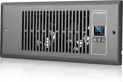
Register Booster Fan

Assembly is EASY!
WE WANT
YOU TO
ENJOY LIFE
AT
GO TO THE PRODUCT LISTING PAGE FOR
AN INSTRUCTIONAL VIDEO!
USER MANUAL
HOW-TO
Register Booster Fan
CONTENTS
Key Features
Product Contents
Installation
Programming
FAQ
Warranty
1
2
2
6
18
20
1
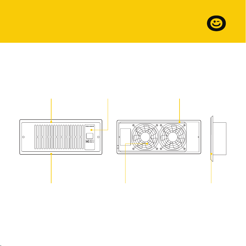
Aluminum Frame
Features an aluminum
frame with CNC-ma-
chined corners and a
white or bronze finish
to give cabinets a
clean look.
Smart Controller
Enables airflow
temperature moni-
toring, hot and cold
temperature triggers,
and fan speed
control.
Dual Ball Bearings
Enables the unit to be
mounted in any
direction. The motor
features dual-ball
bearings with a
67,000-hour lifespan.
Quiet Pwm Motor
PWM-controlled motor
features precise speed
control, reduced noise,
and energy-efficient
DC power.
Stator Blades
Hydro-mechanical
stator blades enable
air to travel farther
even in high-stat-
ic-pressure environ-
ments.
Protective Back
Enclosed in a thermo-
plastic casing with fan
guards to protect users
from high-speed fans
and prevent clogging.
SECTION A
Key Features
2
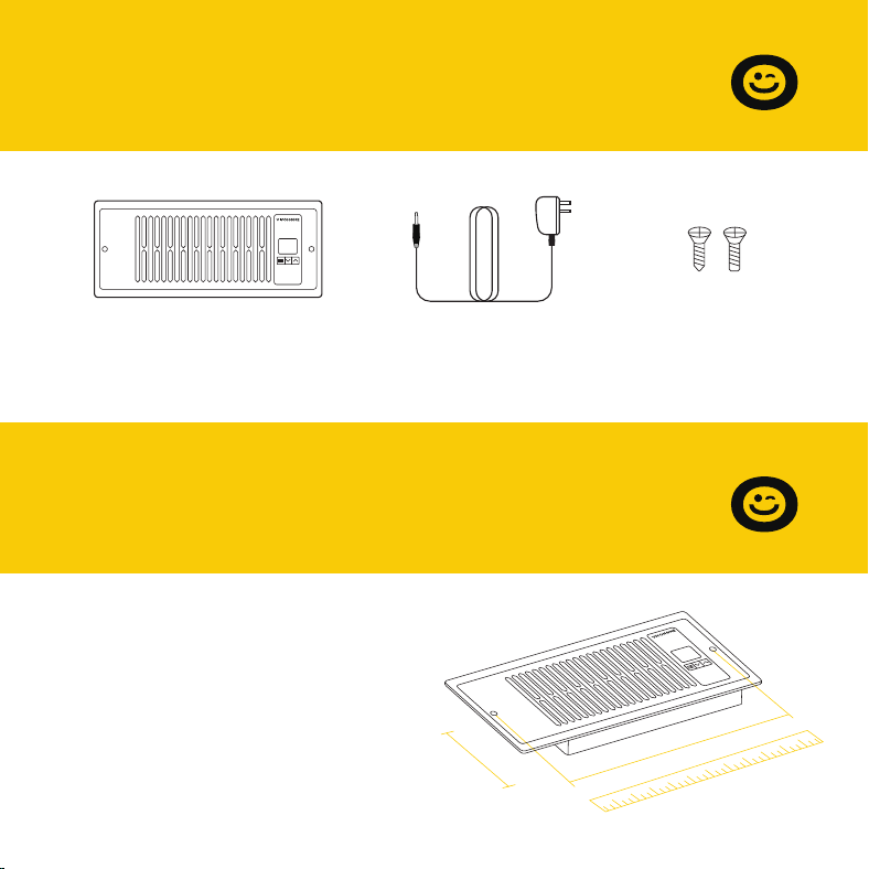
Register Fan
x 1pc
Power Adapter
x 1pc
Screw Set
x 2set
STEP 1
Measure your register vent to make
sure this model will fit. Standard
sizes come in 4'' x 12''.
SECTION B
Product Contents
SECTION C
Installation
4''
12''
3
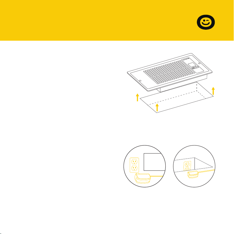
STEP 2
Remove your registration grille. You
may need to use a Philips screwdriver
to remove the mounting screws.
STEP 3
Plug the power adapter into an
outlet. This can be next to your
register or inside your register.
SECTION C
Installation
4''
12''
4
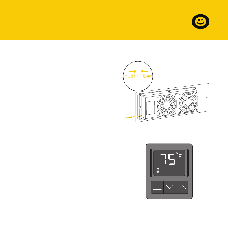
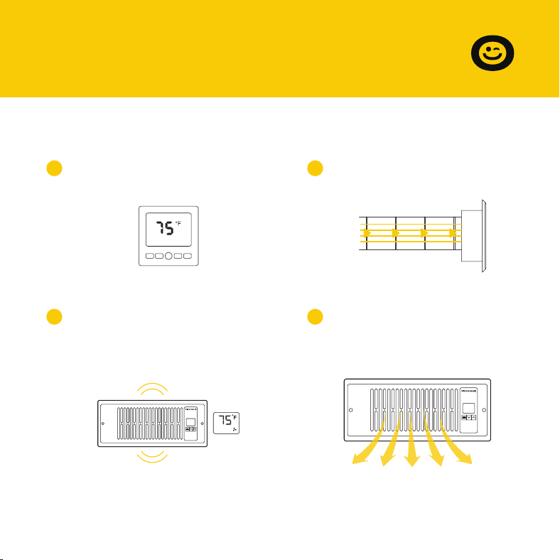
STEP 5
Check the LCD display to make sure
it is lit and displays a numeric value.
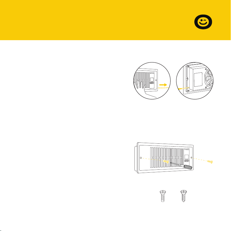
STEP 4
Plug the power adapter's cord into
the power receptacle on the register
fan unit.
SECTION C
Installation
5
STEP 6
Position the register fan to be
mounted.
If the outlet is external, make sure
the cord goes through the gap
between the wall and the mounting
plate.
STEP 7
Drill your existing screws into the
mounting holes to secure the register
fan. If necessary, use the screws
included with your register fan.
If the screw holes do not align, you
may need to drill new holes into your
wall.
OR
SECTION C
Installation
6
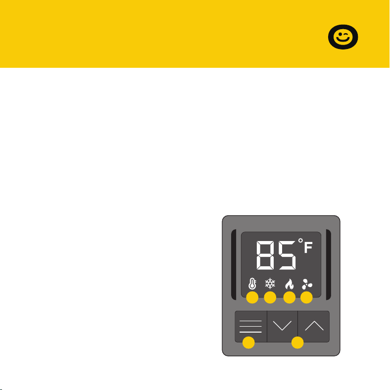
1. MODE BUTTON
Cycles through the unit's modes:
temperature display, cooling
trigger, heat trigger, and fan speed.
SECTION D
Programming
2. UP / DOWN BUTTON
Changes the temperature setting in
the cooling trigger, the heating
trigger, and the fan speed.
3. TEMPERATURE DISPLAY
Displays the current airflow
temperature (not room tempera-
ture) as measured by the probe on
the fan's back case. Used as the
default display.
4. COOLING TRIGGER
Allows you to set a temperature
trigger for the fans to run when
your air conditioner system is on.
5. HEATING TRIGGER
Allows you to set a temperature
trigger for the fans to run when
your central heating system is on.
6. FAN SPEED
Sets the fan's maximum running
speed when the cooling or
heating triggers are tripped to
run.
1 2
3 4 5 6
7
SECTION D
Programming
Important Notes – Please Read
This product is used to boost your existing AC or heater's airflow. It allows
you to set temperature points where the fans will turn on when the
temperature of the airflow falls below or rises above the cooling or heat
trigger setting, respectively. This product has 10 fan speeds, from 1 to 10.
Use the fan speed setting to set your desired airflow boost. Keep in mind
that the faster the fans spin, the louder they will be.
We've designed the fans to ramp up or down instead of quickly turning on
or shutting down to minimize noise and power consumption.
When not changing settings, we recommend that you stay in Temperature
Display mode to monitor and accurately measure the temperature of your
airflow. Do not use your AC or heater's thermostat reading; it does NOT
display the airflow's temperature.
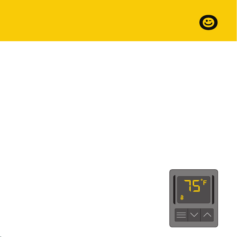
Temperature Display
This mode displays the airflow temperature
measured by the probe. While in this
display mode, the cooling and heating
triggers and the maximum fan speed
setting are still active unless you have
disabled them.
8
SECTION D
Programming
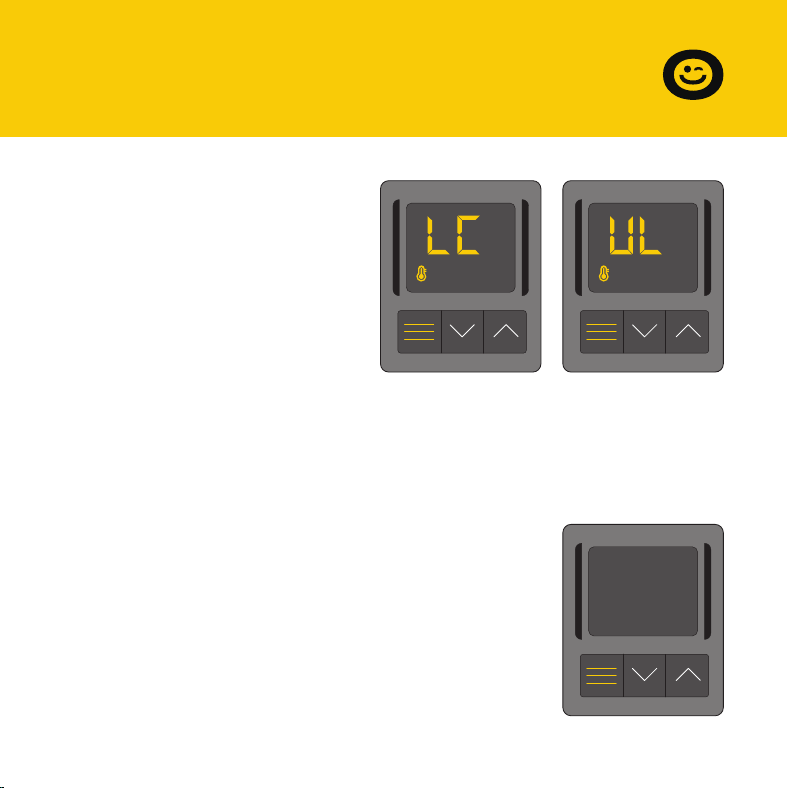
Controller Lock or Unlock
To lock or unlock the controller,
enter the Temperature Mode
and then press the mode button
for three or more seconds. While
the display is locked, it will show
''LC''for one second. You will not
be able to switch modes or
adjust settings, but the fans
Holding the mode button for three or more seconds will unlock the
controller. It will show ''UL'' for one second, and you will be able to switch
modes or adjust settings.
Hide Display
While the controller is locked, you can hide
the display and turn off its backlight by
pressing the mode button. All programs
and settings will continue to work in the
background while the display is hidden.
Press any button to restore the display
again.
will be working in the background.
9
SECTION D
Programming
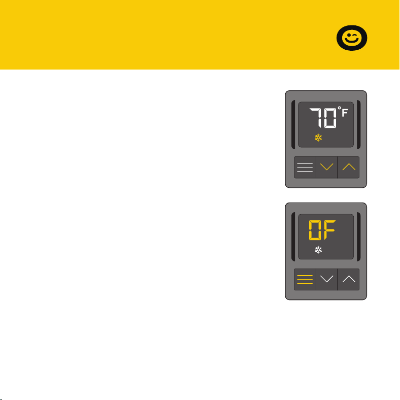
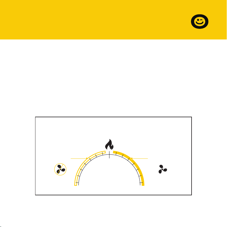
Use this mode to set the temperature trigger for
your air conditioner. Please note that you are NOT
setting your desired temperature.
In this cooling mode, the fans will run if the probe
temperature meets or falls below the trigger’s cold
temperature setting; the fans will not run if the
probe temperature is above the trigger’s cold
temperature setting.
Press the up or down buttons to set the cooling
trigger temperature. To calibrate your register
booster fans, turn on your AC and wait for a few
minutes until the probe temperature stabilizes. Set
your cooling trigger to this number or higher.
To avoid confusion, we recommend disabling the cooling trigger when not
using your AC. To disable it, hold the mode button for three seconds. The
display will show OF. It is also recommended that you return to the
temperature display mode once you finish adjusting your cooling trigger.
Cooling Mode

Cooling Mode
10
Cold air blows through the
duct and into your room.
21
Your air conditioner turns on.
3
When the probe detects that
airflow temperature has fallen
below your Cooling Trigger, it
will activate the fans.
4
The fans will pull cold air
from your duct to boost
your AC output.
TempMode Fan
SECTION D
Programming
11
SECTION D
Programming
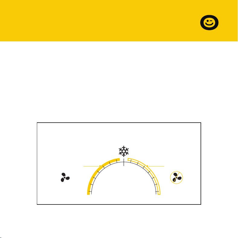
In this cooling mode, the fans will run if the probe temperature meets or
falls below the trigger’s cold temperature setting; the fans will not run if the
probe temperature is above the trigger’s cold temperature setting.
To switch off the cooling mode, press and hold the MODE button for 3
seconds. Press and hold the MODE button for 3 seconds again to resume
the cooling mode.
Temperature you set in
Cooling Trigger
32°F 140°F
Probe Temp °F/°C
Fans Not
Running
Fans Running
12
SECTION D
Programming
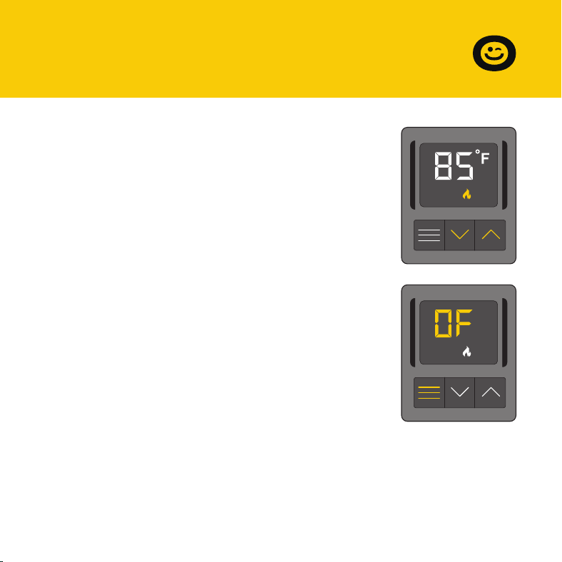
To avoid confusion, we recommend disabling the heater trigger when not
using your heater. To disable it, hold the mode button for three seconds.
The display will show OF. It is also recommended that you return to the
temperature display mode once you finish adjusting your heating trigger.
Use this mode to set the temperature trigger for
your heater. Please note that you are NOT setting
your desired temperature.
In this heating mode, the fans will run if the probe
temperature reaches or exceeds the trigger's
heating temperature setting; the fans will not run if
the probe temperature is below the trigger's
heating temperature setting.
Press the up or down buttons to set the heating
trigger temperature. To calibrate your register
booster fans, turn on your heater and wait for a few
minutes until the probe temperature stabilizes. Set
your heating trigger to this number or lower.
Heating Mode
13
Heating Mode
Heated air blows through
the duct and into your room.
21
Your central heating system
turns on.
3
When the probe detects the
airflow temperature has risen
above your Heating Trigger, it
will activate the fans.
4
The fans will pull heated air
from your duct to boost
your AC output.
TempMode Fan
SECTION D
Programming
14
SECTION D
Programming
In this heating mode, the fans will run if the probe temperature reaches or
exceeds the trigger’s heating temperature setting; the fans will not run if
the probe temperature is below the trigger’s heating temperature setting.
To switch off the heating mode, press and hold the MODE button for 3
seconds. Press and hold the MODE button for 3 seconds again to resume
the heating mode.
Temperature you set in
Heating Trigger
32°F 140°F
Probe Temp °F/°C
Fans Not
Running
Fans Running
SECTION D
Programming
15
We recommend that the operating state should be set to the cooling
mode OR the heating mode during the usage, the fans will be working as
following:
If the heating mode is set to OF state, the fans will be working in the
cooling mode as Page 11; If the cooling mode is set to OF state, the fans will
be working in the heating mode as Page 14.
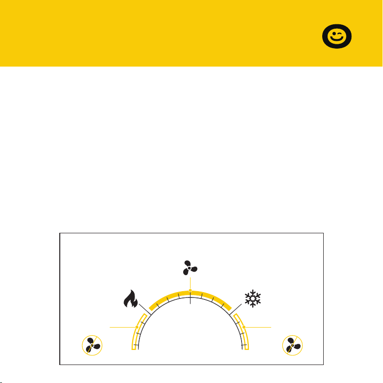
When the heating trigger is below the cooling trigger:
the fans will run if the probe temperature stays between the heating
trigger and the cooling trigger; the fans will NOT run if the probe tempera-
ture is below the heating trigger OR above the cooling trigger.
Temperature Mode
The heating trigger is below the cooling trigger
32°F 140°F
Probe Temp °F/°C
Cooling
Trigger
Heating
Trigger
Fans Not
Running
Fans Running
Fans Not
Running
16
SECTION D
Programming
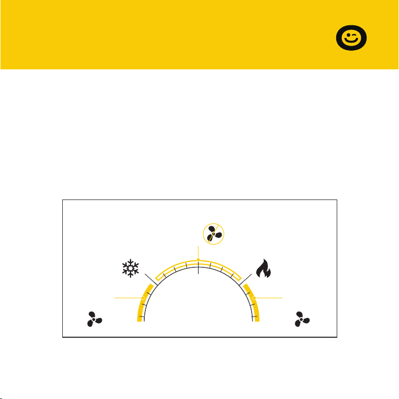
When the heating trigger is above the cooling trigger:
the fans will NOT run if the probe temperature stays between the heating
trigger and the cooling trigger;
the fans will run if the probe temperature is above the heating trigger OR
below the cooling trigger.
Temperature Mode
The heating trigger is above the cooling trigger
32°F 140°F
Probe Temp °F/°C
Cooling
Trigger
Heating
Trigger
Fans
Running
Fans
Running
Fans Not
Running
17
SECTION D
Programming
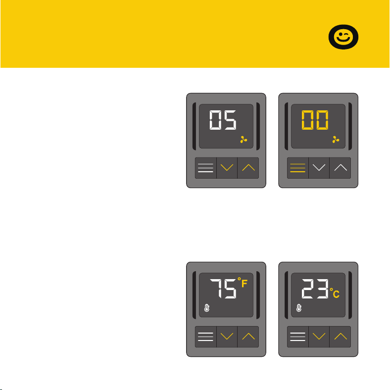
Air Flow Mode
This mode allows you to set a
maximum fan speed at which
they will actively run until you
leave it. In Air Flow Mode, the fan
will always operate at the set
speed without being limited by
the temperature setting. Pressing
up or down will change
Fahrenheit or Celsius
To change the temperature scale
between Fahrenheit and Celsius,
press both
the up and down buttons
simultaneously until the letters
change. All digits displayed will
be automatically converted to
the designated scale.
the fan speed and determine the level of airflow
boosting. Holding the MODE button will set the fan speed to 0.
Keep in mind that the faster the fans spin, the louder they will be.

18
Q: Can I be able to mount this fan on my ceiling?
A:
For safety reasons, we do not recommend mounting the fan on your
ceiling.
Q: Will I be able to mount this fan on a baseboard style register?
A:
No. Because of the tilted design, the fan will not have the clearance to
be properly mounted.
Q: My register is bigger than my fan's rear insert. How can I fit this fan onto
my register?
A:
We can only recommend using the appropriately sized fan for your
register. Contact customer service for fitment issues.
Q: Does this register booster fan have fittings to use a filter with?
A:
This product is not specifically designed to be used with filters.
Q: Can I reverse this fan's airflow?
A:
The fan's boosted airflow cannot be reversed, nor can the fans be
flipped.
SECTION E
FAQ

19
Q: What temperature does the register booster fan detect?
A:
The fan's backside probe reads the airflow temperature of your register
vent. Please note this temperature may vary from your home thermo-
stat's reading.
FAQ
Q: My register booster fan is too loud. How do I decrease the fan noise?
A:
To minimize the noise coming from the fan, decrease the maximum fan
speed. Refer to page 17.
Q: My fan runs all the time when I don't need it to. How do I turn it off?
A:
The heating and cooling triggers may be active at the same time. Disable
the trigger you are not using by holding the mode button until the
screen displays OF.
SECTION E
FAQ

20
The VIVOHOME warranty program is our commitment to you.
We are committed to providing you with a high-quality product that meets
your needs and expectations. To demonstrate our confidence in the
durability and performance of our products, we offer the following
warranty.
SECTION E
Warranty
This warranty program applies to any orders, purchases, receipts, or use of
any products sold by VIVOHOME and is valid for a period of 1 year from the
date of purchase. However, please note that this warranty period is only
valid for the original order. If you receive a replacement order during the
warranty period, it will not include a separate warranty period.
WARRANTY COVERAGE

SECTION E
Warranty
21
This warranty does not cover damage resulting from misuse, accident,
unauthorized modification, or any other circumstances not directly related
to the manufacturing and design of the product, including but not limited
to:
Parts lost during use.
Normal wear and tear of products or parts.
Incorrect installation (such as using the wrong voltage) or assembly.
Exceeding the bearing capacity of the product.
Use under extremely harsh conditions.
Improper cleaning or maintenance.
Damage caused by any reason other than the intended use of the
product.
Indirect loss or damage caused by the product.
WARRANTY EXCLUSIONS
●
●
●
●
●
●
●
●

VIVOHOME will provide technical support, replacement, refund, or other
solutions based on the nature of the issue. If you wish to return the original
package for any reason, please contact us for confirmation before
proceeding. You can expect to receive a response within 48 hours.
Thank you for choosing VIVOHOME. We are committed to ensuring the
quality and satisfaction of your purchase. If you have any questions or
need assistance, please do not hesitate to contact our customer service
team.
If you find any defects that affect the use of the product or if the product
stops working and cannot be repaired during the warranty period, please
contact our customer service team at our email or via Amazon & app’ s
direct messaging service as soon as possible. Provide the following
information to expedite the process:
HOW TO MAKE A WARRANTY CLAIM
Order number
Images and/or videos illustrating the issue
A detailed description of the problem
●
●
●
22
SECTION E
Warranty

THANK
YOU!
Thank You for Purchasing from
Made in China
NOTE:
To continuously improve its products, reserves the right to
modify this information without prior notification.
For any questions regarding assembly, please watch the video on the
product page or contact our customer service. Our customer service will
Thank you for using products in your home!