User Guide
Three-Way 180° Occupancy and Vacancy Sensor Switch Please read all
instructions before installing the MEW-OVS100W Sensor switch.
www.MaxximaStyle.com
MEW-OVS100W
IMPORTANT:If you have any doubts about your specific
wiring configuration or installation requirements,please
consult a licensed electrician.
SPECS
120V/277VAC, 60Hz
120V 800W Incandescent Lamp
800VA Fluorescent Lamp (Rapid Start)
277V 1200VA Fluorescent Lamp (Rapid Start)
Voltage
Max Lamp Load
1/6 hp
Preset intervals of 15 sec (Test),1 min,
5 min, 15 min, and 30 min
Max motor load
Time Delay Adjustment
Indoor use only
32˚ to 131˚F (0˚ to 55˚C)
95% RH, non-condensing
Environment
Operating Temperature
Humidity Range
180˚ (at optimal temperature of 20˚ to 25˚C)
2
720 ft 2 (47m )
Coverage Range
Coverage Area
TOOLS NEEDED
You will need an insulated flathead screwdriver, wire strippers, and a
small flathead screwdriver to adjust the sensor dials.
DESCRIPTION
The MEW-OVS100W Sensor switch is designed to replace a standard light
or fan switch. This device can automatically turn lights or a fan on and off
by detecting motion from a heat-emitting source such as a person
entering an area. The lights or fan will stay on until no motion is detected
and the time delay has expired. This product offers optimal coverage for
random traffic areas such as hallways, stairways,
or large spaces with multiple entries. Use indoors only.
COVERAGE AREA
● The sensor must have a clear and unobstructed view of the area. If an
object blocks the sensor’s lens, the sensor may not detect motion and
may turn the lights or fan off even if someone is in the area.
Windows, glass doors, and other transparent barriers will
obstruct the sensor’s view and prevent motion detection.
● The coverage area data is measured under the best temperature
condition (20 to 25˚ C), and a higher or lower temperature may not
lead to an ideal coverage area (see figures 1 and 2).
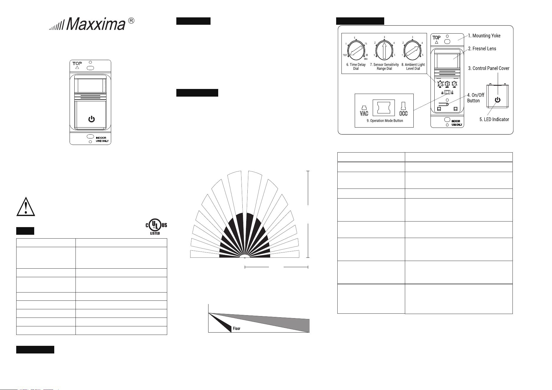
Figure 1: Sensor coverage area (top view)
30ft
(9.1m)
12ft
(3.7m)
30ft
(9.1m)
4ft
(1.2m)
6ft
(1.8m)
Figure 2: Sensor coverage area (side view)
SWITCH OVERVIEW
Figure 3:
MEW-OVS100W Sensor switch diagram
1. Mounting Yoke
2. Fresnel Lens
3. Control Panel
Cover
4. On/Off Button
5. LED
Indicator
Lets you mount the switch to the wall.
Detects motion.
Covers the switch’s adjustment dials.
Remove the cover to see the dials.
Lets you turn the light or fan on or off.
Indicates when the sensor detects motion. The
green LED lights the On/Off button while the lights
or fan are off. When they are on, the LED turns off.
6. Time Delay Dial
Controls how long the light or fan stays on after
no motion is detected.
7. Sensor Sensitivity
Range Dial
8. Ambient Light Level
Dial
9. Operation Mode
Button
Adjusts the sensitivity setting to avoid unwanted
detection such as hallway traffic or adjacent
movement.
Prevents the sensor from automatically turning
the lights or fan on if the area has enough
ambient lighting.
The sensor has two positions that correspond to
operation modes: vacancy (when the button is
pressed) and occupancy (when the button is
released).
WARRANTY
Maxxima extends a 1 year limited warranty to the original purchaser that the products
purchased are free from defects in material and/or workmanship only.
The limited warranty is not transferable. This offer does not constitute in any way a
product guarantee and Maxxima does not hereby assume any obligation whatsoever
beyond sending a replacement product at no charge during the warranty period
INSTALLATION AND WIRING
Line side
Load side
Connected to the circuit breaker
Connected to the light or fan
Prepare the Wires
1. Tag the wires currently connected to the existing switch, so
you can easily identify them later.
IMPORTANT:For three-way applications,one of the screw
terminals from the switch you’re removing may be black or
be labeled as Common.Tag this wire with electrical tape
and identify as Line or Load in both the sensor wall box
and the remote wall box.
2. Disconnect the wires.At this point,you have three options.
You can install the MEW-OVS100W Sensor switch on it's
own, with a regular three-way switch or install it with
another MEW-OVS100W Sensor switch.
WARNING: Before installing the MEW-OVS100W
Sensor switch,disconnect power to the wall
switch box by turning off the circuit breaker or
removing the fuse for the circuit. WARNING:
Tightly secure the ground wire to ensure that the
sensor functions properly. IMPORTANT: A
neutral wire is required for the switch to work
properly.If the existing wiring does not match the
description for a two-pole circuit,or if you do not
have a neutral wire,consult a qualified electrician.
Introduction
You can install the MEW-OVS100W Sensor switch with a
regular three-way switch,or you can install two MEW-
OVS100W Sensor switches for maximum coverage.When
installing with a regular three-way switch, the MEW-
OVS100W Sensor switch only works when properly installed
on the load side.See the table below.
Prepare the Switch Box
1. After the power is turned off at the circuit breaker box,
remove the existing wall plate and mounting screws.
2. If applicable,pull the old switch out from the wall box
with the attached wires.See figure 4 for a three-way
wiring application.
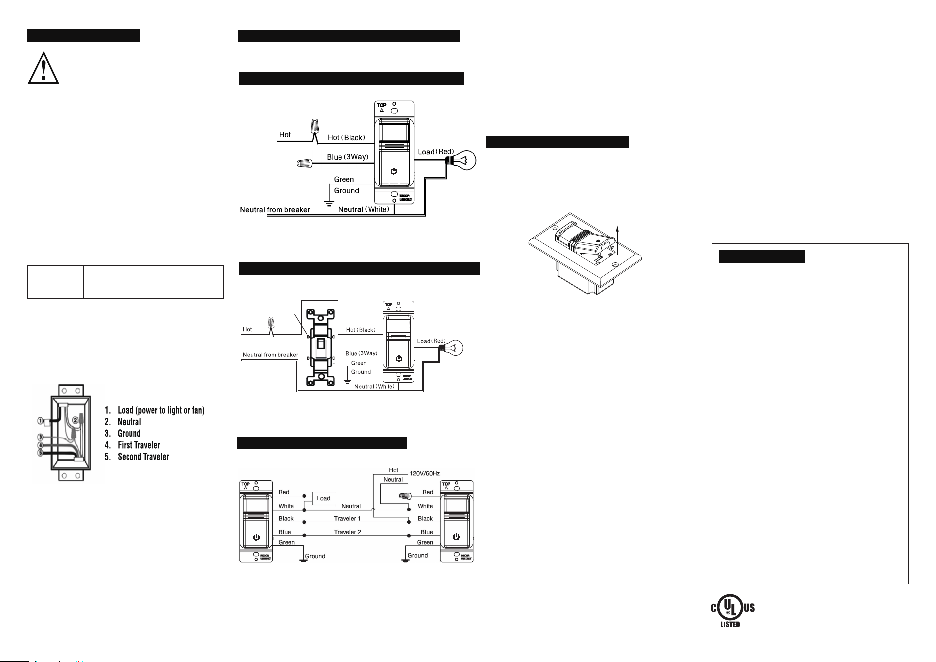
MEW-OVS100W Sensor with a Regular Three-Way Switch
Figure 5: Black to Black and Common, White wires together,
Green to Ground, Red to Load and Blue to Traveler.
1. Insert the switch into the wall box by positioning the lens at
the top and the On/Off button at the bottom.
2. Secure the switch to the wall box with the screws provided.
To program the sensor, first remove the cover:
1. Insert a small flathead screwdriver into the notch located
on the bottom of the cover below the sensor.
2. Gently lift the screwdriver upward to unlatch the cover
(see figure 7).
ADJUSTMENT AND PROGRAMMING
Figure 7: Lift the screwdriver upward to open the cover.
Vacancy: In vacancy mode (manual on/off, auto off), press the
On/Off button to turn the light or fan on or off like you would a
standard switch. The MEW-OVS100W Sensor switch
automatically turns off the lights or fan after the time delay.
Note: In VAC mode, it is closed manually and must be opened
manually. If it's sensed in 30 seconds after the automatic
closing, it will still be automatically opened. After 30 seconds,
need to manually turn on the switch.
Occupancy: In occupancy mode (auto on, auto off with auto
reset), the lights or fan turn on automatically when the space is
occupied. The MEW-OVS100W Sensor switch automatically
turns off the lights or fan after the time delay. If the lights or fan
are turned off manually, automatic on is re -enabled when no
motion is detected for one minute. This way, the lights or fan will
remain off if they were deliberately turned off.
Note: In OCC mode, if the switch is manually turned off, the
switch will work after 15 seconds.
IMPORTANT: When installing two MEW-OVS100W Sensor
switches,either sensor can turn the lights on. For the lights
to turn off, both sensors must time out, or you must
manually turn them off.
Adjust the Time Delay
The Time Delay Dial, labeled as TIME, controls how long the light
or fan stays on after no motion is detected. The minimum setting
is 15 seconds (fully counterclockwise) and the maximum
setting is 30 minutes (fully clockwise). Adjust the setting as
desired for your area.
● The Sensor Sensitivity Range Dial, labeled as SENSE, lets
you adjust the sensor to avoid unwanted motion detection
such as hallway traffic.
● To decrease sensitivity, turn the setting counterclockwise.
To increase sensitivity, turn the setting clockwise. The
sensor’s default setting is 3 (75%). You can adjust it from
setting 1 (50%) to setting 5 (100%).
Lights or Fan Will Not Turn On
Push the On/Off button. The load should turn on. If not:
1. Check the light bulb and/or motor switch on the fan.
2. Turn off power to the circuit and check the wire
connections.
Lights or Fan Will Not Turn Off
● Ensure that no motion is occurring in the coverage area
until the set time period.
● Ensure that the sensor is at least 6 ft (2 m) away from
devices that are a significant heat source (e.g., heater,
heater vent, and high wattage light bulbs). Hot air
currents and heat-radiating devices such as 100W
incandescent bulbs) can cause false detection.
● Push the On/Off button to Off. If the lights or fan do not turn
off, turn off power to the circuit and check wire connections.
Lights or Fan Turn Off Too Quickly
The time delay or sensitivity range may be improperly
set. Refer to the Adjustment and Programming section.
Lights or Fan Turn on When Movement Is
Detected in Adjacent Areas
If the sensor’s location gives it a view of other areas or
hallways,the lights will turn on when motion is detected
in those areas. Try adjusting the sensitivity range (refer
to the Adjustment and Programming section). You may
need to move the sensor to another location.
Lights or Fan Turn on When the Area is Unoccupied
The sensor may be mounted too closely to an air
conditioning or heating vent. Move the sensor to another
location or close the vent.
TROUBLESHOOTING
Adjust the Ambient Light Level
The Ambient Light Level Dial, labeled as LIGHT, lets you
adjust the sensor to detect whether other light sources
(such as sunlight) are enough to light the space without
turning on the lights. If you would like the sensor to consider
the amount of ambient light in your area, turn the dial
counterclockwise. If you would rather not use the ambient
light level, leave it on the maximum, default setting (5).
This will allow the sensor to turn the light on and off
regardless of ambient light.
MEW-OVS100W
Figure 4: Black to Black, Red to Load, White wires
together, Green to Ground, and Blue not connected.
Determine which electrical box has a load connection. This is the box
where you will install the MEW-OVS100W Series sensor switch.
• Wire according to the wiring diagram below (see figure 4).
Wiring a MEW-OVS100W Sensor Switch
3. Attach the new cover plate and secure it to the wall box with
the screws provided.
4. Restore the power to the circuit by turning on the breaker or
replacing the fuse.
Finish Installation
Adjust the Sensitivity Range of the Sensor
• Wire according to the wiring diagram below (see figure 6).
Two MEW-OVS100W Sensor Switches
Figure 6: Connect the Black wires together, Blue to Blue,
Greens to Ground, White wires together, Cap
the Red on the
Line Side, and Connected Red on the Load Side to the Load.
• Wire according to the wiring diagram below (see figure 5).
Common screw
is dark-colored
MEW-OVS100W Sensor in a Single Pole Application
Not Connected
(Capped)
(Line)
(Line)
(Line)