INSTALLATION GUIDE / USER MANUAL
PowerZone® Connect PRO • 2000.2/2000.2D • 4000.4/4000.4D
2
Technical and Safety Notices
Please read the following important technical,
safety and environmental notices before
installing and using your amplifier.
Technical Notices
All reasonable design and engineering steps have
been taken to ensure that these amplifiers always
perform satisfactorily in their intended application and
environment and will provide appropriate levels of
support to ensure that all reasonable customer needs
and expectations are met. Such support however is
contingent on the following provisions.
• These amplifiers are Class I products and must be
connected to a mains socket outlet with a protective
earthing connection.
• These amplifiers should always be installed by
competent and qualified personnel. Amplifier
damage or failure caused by installation or
operational errors may invalidate support, warranty
or guarantees of performance.
• These amplifiers are not suitable for use in locations
where they may be accessible to minors.
• These amplifiers are intended to be used specifically
for the amplification of audio signals and for
connection to moving-coil loudspeaker systems.
Use of these amplifiers for amplification of signals
outside the audio band (20 Hz to 20 kHz) or to drive
transducers other than moving-coil loudspeakers
may invalidate support, warranty or guarantees of
performance.
• These amplifiers should only be used within
professionally installed and configured audio systems
comprising input and output ancillary equipment
that is known to be of an appropriate level of
performance and in good operating condition. Any
damage to, or unsatisfactory performance from,
these amplifiers caused by inadequate or failed input
or output ancillaries may invalidate support, warranty
or guarantees of performance.
• These amplifiers are intended to be installed and
operated indoors in a controlled environment
(pollution degree, PD2) within an ambient
temperature range of 0°C to 40°C. These amplifiers
are not intended for use above 2000 meters
above sea level. Amplifiers installed or operated in
environments outside these limits may invalidate
support, warranty or guarantees of performance.
• Specific warranty terms are the responsibility of the
amplifier reseller.
Safety and Environmental Notices
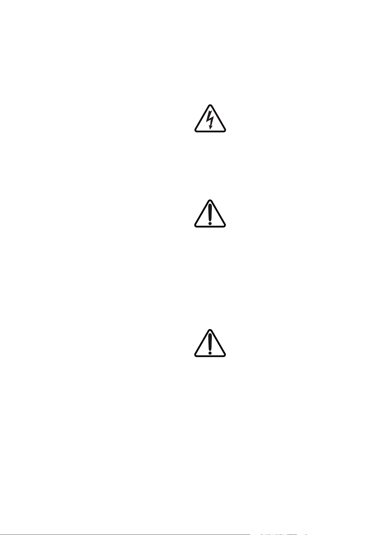
Note: The intent of the lightning flash with arrowhead
symbol in a triangle is to alert the user to the presence
of uninsulated “dangerous voltage” within the product’s
enclosure that may be of sucient magnitude to
constitute a risk of electric shock to persons.
Note: The intent of the exclamation point within an
equilateral triangle is to alert the user to the presence
of important safety, and operating and maintenance
instructions in this manual.
WARNING! TO PREVENT FIRE OR ELECTRIC
SHOCK, DO NOT EXPOSE THIS EQUIPMENT TO
RAIN OR MOISTURE.
Ambient Temperature Note: If this equipment
is operated in a confined or multiple rack
installation, the internal ambient operating
temperature may exceed the external ambient
temperature. It is important to ensure in these
circumstances that the published maximum
operating temperature for the equipment
is not exceeded.
Reduced Air Flow: Ensure that rack or other
closed installation does not restrict the cooling
airflow required for safe and reliable operation
of the equipment.
3
Technical and Safety Notices
Important Safety Instructions
• Read these instructions.
• Keep these instructions.
• Heed all warnings.
• Follow all instructions.
• Do not use this apparatus near water.
• Clean only with a dry cloth.
• Do not block any ventilation opening. Install in
accordance with the manufacturer’s instructions.
• Do not install near any heat sources such as radiators,
heat registers, stoves, or other apparatus (including
amplifiers) that produce heat.
• To reduce the risk of electrical shock, the power cord
shall be connected to a mains socket outlet with a
protective earthing connection.
• Do not defeat the safety purpose of the polarized
or grounding type plug. A polarized plug has two
blades with one wider than the other. A grounding
type plug has two blades and a third grounding
prong. The wide blade or the third prong are
provided for your safety. If the provided plug does
not fit into your outlet, consult an electrician for
replacement of the obsolete outlet.
• Protect the power cord from being walked on
or pinched particularly at plugs, convenience
receptacles, and the point where they exit from the
apparatus.
• Do not unplug the unit by pulling on the cord, use the
plug.
• Unplug this apparatus during lightning storms or
when unused for long periods of time.
• Refer all servicing to qualified service personnel.
Servicing is required when the apparatus has been
damaged in any way, such as power supply cord or
plug is damaged, liquid has been spilled or objects
have fallen into the apparatus, the apparatus has
been exposed to rain or moisture, does not operate
normally, or has been dropped.
• The appliance coupler, or the AC Mains plug, is the
AC mains disconnect device and shall remain readily
accessible after installation.
• Adhere to all applicable local codes.
• Consult a licensed professional engineer when
any doubt or questions arise regarding a physical
equipment installation.
• Do not use any aerosol spray, cleaner, disinfectant or
fumigant on, near or into the equipment
Environmental Statement
This product complies with international directives,
including but not limited to the Restriction of Haz-
ardous Substances (RoHS) in electrical and electronic
equipment, the Registration, Evaluation, Authorization
and restriction of Chemicals (REACH) and the disposal
of Waste Electrical and Electronic Equipment (WEEE).
Consult your local waste disposal authority for guid-
ance on how to properly recycle or dispose of this
product.
Additional Safety Notices

4
Introduction and Overview
1. Introduction
PowerZone Connect PRO power amplifiers
have been designed to provide configurable,
consistent and reliable high performance audio
power amplification for residential, commercial
and entertainment applications.
Please read this manual fully before installing
and using an amplifier. If you have any questions
regarding amplifier configuration, installation or
operation please contact our technical support.
Following this introduction, the manual is divided into
sections covering the following topics:
2. Overview
3. Carton Contents
4. Installation
5. Configuration
6. Connections
7. Operation
8. Specifications
2. Amplifier Overview
PowerZone Connect PRO 2000.2/2000.2D and
4000.4/4000.4D amplifiers are full-rack width, 2U
format power amplifiers that can drive both high
impedance (Hi-Z, 70 V / 100 V) transformer coupled
loudspeakers and conventional low impedance (Lo-Z @
4/8 Ω) loudspeakers.
The amplifiers provide four or eight analog inputs
depending on model type, one stereo S/PDIF digital
input, 4x4 Dante
®
channels on selected models, and
either two or four outputs.
PowerZone Connect PRO amplifier model rack widths,
output channel counts and power outputs are as
follows:
PowerZone Connect PRO 2000.2/2000.2D
Mode Channels Max Rated Output
per Channel
Hi-Z Two 1000 Watts
Lo-Z Two 1000 Watts
PowerZone Connect PRO 4000.4/4000.4D
Mode Channels Max Rated Output
per Channel
Hi-Z Four 1000 Watts
Lo-Z Four 1000 Watts

5
Introduction and Overview
2.1 Connections
PowerZone Connect PRO signal input and output
connections are accomplished via RCA Phono and
Euroblock style connectors. A GPIO (General Purpose
In/Out) Euroblock connector enables some amplifier
functions to be controlled, and wireless or RJ45
socket Ethernet network connection options are also
provided.
PowerZone Connect PRO 2U amplifiers incorporate a
front panel mounted power button. Press the button
once to switch the amplifier on or o. Amplifier power
management behavior can be configured via the
PowerZone Control web app Settings Menu described
in Section 5 of this manual.
2.2 Network Features
PowerZone Connect PRO amplifiers are TCP/IP
network connected devices that require a wired
or wireless network connection to access their
configuration menus. The configuration menus are
accessed via the PowerZone Control Center desktop
application or PowerZone Control web app and cover
Input, Zone, Output and General Settings functions.
The configuration menus are fully described in
Section 5 of this manual.
Audinate Dante
®
PowerZone Connect PRO amplifiers are optionally
compatible with Audinate Dante
®
audio over IP (AoIP)
networks and installations.
Dante
®
equipped versions of PowerZone Connect PRO
amplifiers enable the transmission and receipt of digital
audio over an Ethernet network using the IP based
Dante
®
protocol. Configuration and management of the
IP routing for Dante
®
digital audio, including the setting
of network parameters such as IP addresses and
subnet masks, is administered by Audinate’s Dante
®
Controller software application. Dante
®
Controller
downloads and comprehensive guidance on the
configuration and installation of Dante
®
based audio
over IP can be found at: www.audinate.com/products/
software/dante-controller.
2.3 Dimensions
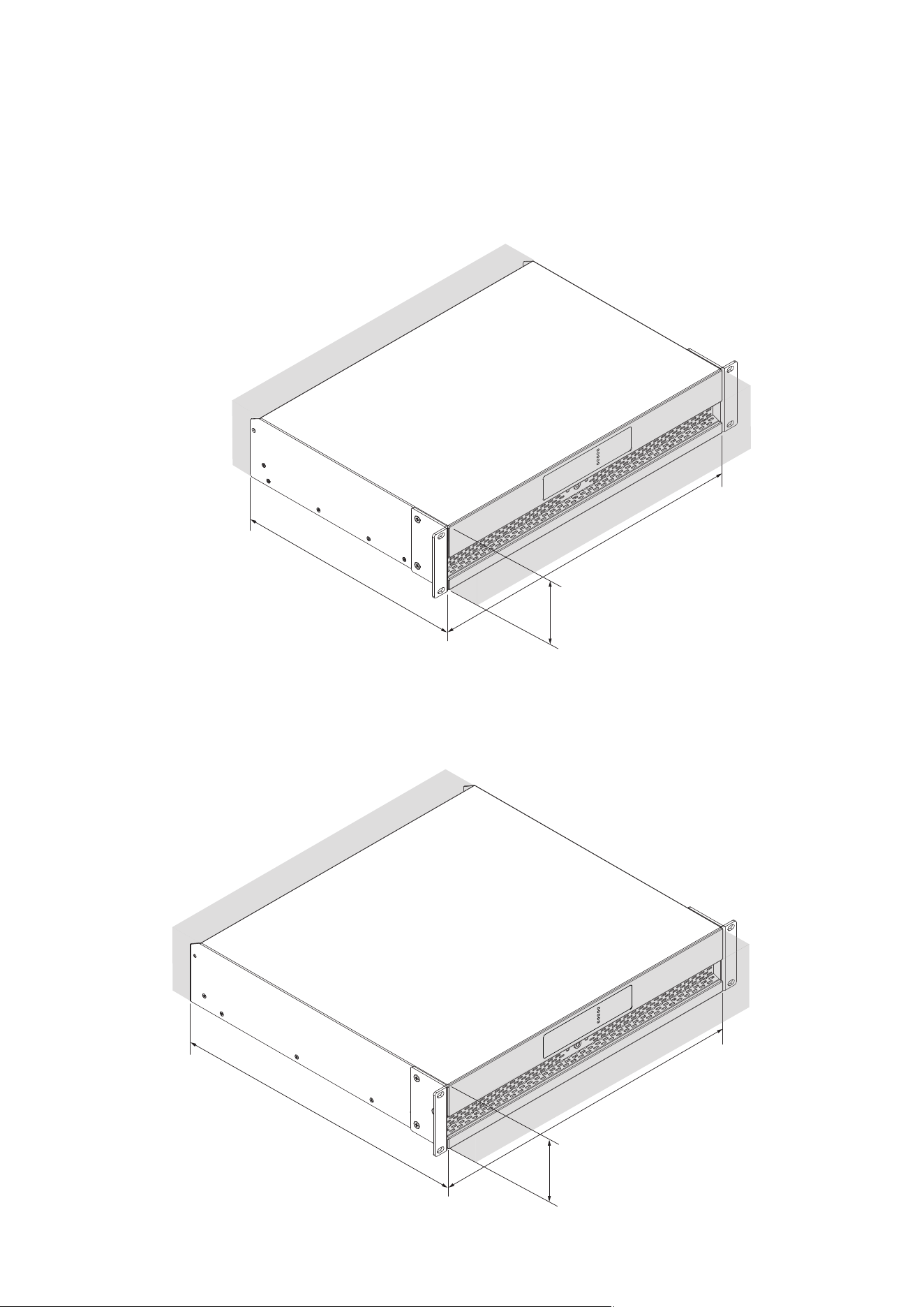
PowerZone Connect PRO amplifier dimensions and
features are illustrated in Diagrams 2A and 2B. The
amplifiers are primarily intended for installation in
an equipment rack but in some cases can also be
used free standing. They are fan-cooled and must
be installed such that ventilation apertures are not
obstructed.
2.4 Firmware
It is strongly recommended that the firmware
version installed in the amplifier in use is checked
initially, and regularly thereafter. If updated firmware
is available, the amplifier should be updated as a
priority.
The firmware installed in the amplifier can be identified
and updated by selecting the Device option in the
PowerZone Control web app Settings Menu.
Firmware can be downloaded either directly within the
PowerZone Control Center desktop application or from
the Sonance website at sonance.com.
3. Carton Contents
PowerZone Connect PRO amplifiers are shipped in a
cardboard carton containing the amplifier unit, a mains
cable appropriate for the sales territory, an accessory
pack, and a document pack. The full contents are listed
below.
• Amplifier unit
• Mains power cable
• Input connector x 2 (or 4)
• GPIO socket connector
• Output connector x 2 (or 4)
• Rack Mount Ears (Fitted) x 2
• Rear Support Bracket x 2 (4000.4/4000.4D only)
6
Overview
Diagram 2A
PowerZone Connect PRO two channel amplifier dimensions 2000.2/2000.2D.
(Shaded area defines ventilation space.)
Diagram 2B
PowerZone Connect PRO four channel amplifier dimensions 4000.4/4000.4D.
(Shaded area defines ventilation space.)
440 mm
17.2 in
440 mm
17.2 in
88 mm
3.5 in
88 mm
3.5 in
320 mm
12.6 in
414 mm
16.3 in
7
Installation
4. Amplifier Installation
4.1 Rack Mounting
PowerZone Connect PRO 2U amplifiers are supplied
with rack ears fitted. The installation and equipment
rack should be configured to provide appropriate
ventilation airflow in the front and rear of the amplifier.
Ventilation apertures are located on the front and
rear of the ampifier and must not be obstructed. It is
important to retain at least 80 mm (3.1 in) free space
for airflow in front and behind the amplifier.
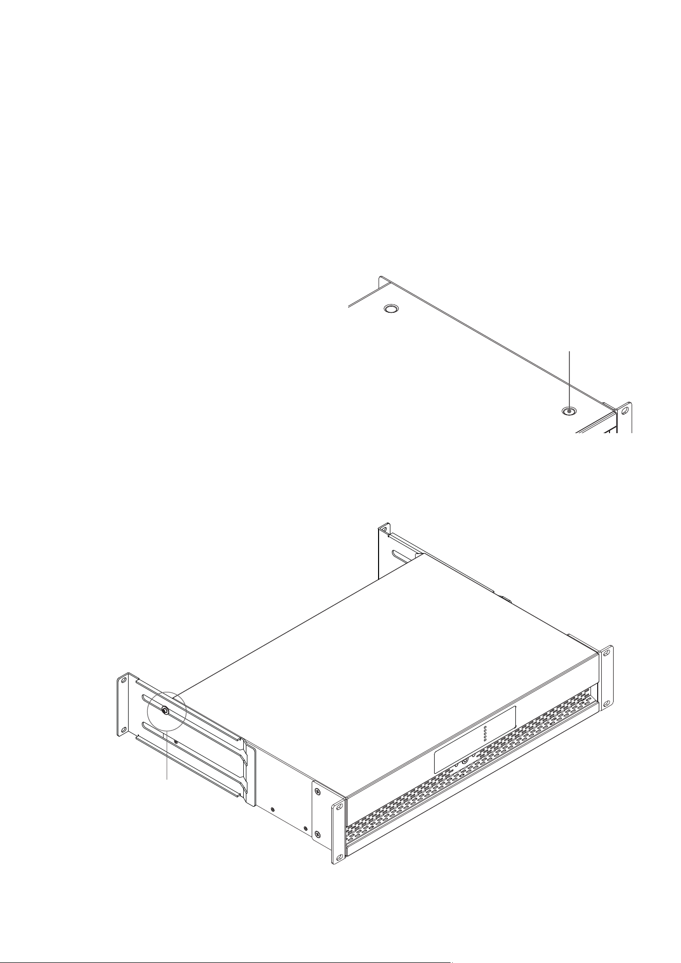
In addition to the rack mount ears, optional rear rack
support hardware is available and can be attached
to the amplifier. Rear support hardware may be
appropriate if the amplifier is to be used in a mobile
rack or potentially be subject to significant movement.
Diagram 4A illustrates the use of rack mount rear
support hardware.
Diagram 4A
PowerZone Connect PRO
Rack Support hardware. 2 positions.
Rear Support + Button +
1 x M4 x 8
4.2 Free-standing
If not installed in an equipment rack, PowerZone
Connect PRO 2U amplifiers can be placed free-
standing on a flat surface. Adhesive rubber feet are
supplied for this purpose. Diagram 4B illustrates the
adhesive foot locations.
Adhesive Foot
4 positions
Diagram 4B
PowerZone Connect PRO
Adhesive feet.

8
Configuration
5. Configuration
Before making input, output, and GPIO connections,
establish the initial PowerZone Connect Pro amplifier
configuration.
Important: Configure the amplifier output format
appropriately for the connected speakers before making
output connections.
Configuration requires that PowerZone Connect PRO
amplifiers are connected to mains power and network
services. These connections are described in the
following two sections.
5.1 Mains Power Connection
PowerZone Connect PRO amplifiers incorporate a power
factor corrected power supply and can be used with
mains input voltage from 100 V AC to 240 V AC, 50 / 60
Hz. Use the mains cable supplied with the amplifier and
connect it to a switched mains supply.
Press the front panel power button to switch on the
amplifier. After a short delay the front panel Status
indicator will illuminate green.
5.2 Network Services
PowerZone Connect PRO amplifiers can be configured
using the PowerZone Control Center desktop application
or the PowerZone Control web app.
The amplifier can be accessed through a wired Ethernet
connection or through its built-in Wi-Fi access point for
initial wireless setup.
5.2.1 Wired (Ethernet) Network Connection
To connect a PowerZone Connect PRO amplifier to a
TCP/IP network using a wired Ethernet connection, follow
the steps below.
1. Use an Ethernet cable to connect the amplifier rear
panel Network Control socket to a network router or
switch, or directly to an Ethernet-equipped laptop or
desktop computer.
2. Connect the amplifier to mains power using the
supplied mains cable. Wait for the front panel Network
indicator to illuminate green to indicate that the amplifier
has network connectivity.
3. PowerZone Connect PRO amplifiers are configured for
DHCP by default. When connected to a network with a
DHCP server, the amplifier will automatically be assigned
an IP address. If needed, use the PowerZone Control
Center desktop application or a network scanning app to
identify the amplifier on the network.
4. If a DHCP server is not available, configure the laptop
or desktop computer with a fixed IP address in the
same IP range as the amplifier’s default LAN IP address.
For example, use IP address 192.168.64.10, subnet mask
255.255.255.0 (or prefix /24), and gateway 192.168.64.1.
5. Open the PowerZone Control Center desktop
application and select the amplifier to configure it.
Alternatively, open a web browser and enter the amplifier’s
IP address. The PowerZone Control web app interface will
open to enable amplifier configuration as required.
Note: If a PowerZone Connect PRO amplifier using DHCP is
power cycled, it is possible that the TCP/IP network router
will assign it a dierent IP address, leaving its configuration
page inaccessible via the previous address. If this occurs,
use the PowerZone Control Center desktop application or
a network scanning app can be used to identify the new IP
address. DHCP and Fixed IP address option settings can be
found in the Settings Tab menu described in Section 5.3.
Note: The second network socket present on the amplifier
rear panel is intended for Audinate Dante
®
AoIP network
connection only. It cannot be used for PowerZone Connect
PRO control connection.
5.2.2 Wireless (Wi-Fi) Network Connection
PowerZone Connect PRO amplifiers include a built-in
Wi-Fi access point that can be used for initial wireless
configuration or connect it to an existing Wi-Fi network.
To connect directly to the amplifier using Wi-Fi, follow the
steps below.
1. Connect the PowerZone Connect PRO amplifier to
mains power using the supplied mains cable and wait for
the front panel Wi-Fi indicator to illuminate green.
2. Use a mobile, laptop or desktop device to search for
available Wi-Fi networks. Connect to ‘Sonance PZcP
(model) (serial number)’ using the password, ‘password’.
The amplifier serial number can be found on its rear panel.
3. Open a mobile, laptop or desktop device web browser
and enter the following IP address: 192.168.4.1. The
amplifier configuration web interface will open in the
browser to enable amplifier configuration as required.
4. To connect the amplifier to an existing Wi-Fi network,
select Settings > WiFi > WiFi Mode > Client in the
PowerZone Control web app, then enter the required Wi-
Fi network name and password and apply changes.
5. Once the amplifier is configured in Wi-Fi Client mode,
access the amplifier from a device connected to the same
Wi-Fi network. It is strongly recommended that the
PowerZone Connect PRO amplifier Wi-Fi password is
changed following initial wireless connection.
9
Configuration
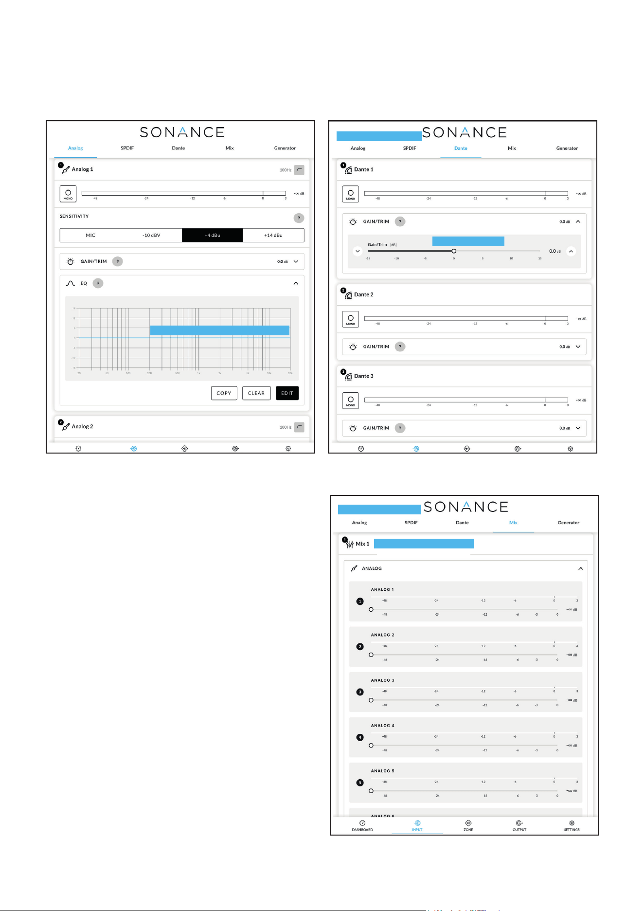
5.3.1 Input Tab
The Input tab provides configuration controls for each
amplifier input channel.
For each analog input, the following parameters are
available:
• Input name
• Mono/Stereo selection
• Input sensitivity
• High-pass filter
• Gain trim
• Five band equalisation
Click or tap the input name to rename the input. The
high-pass filter button enables a 100 Hz high-pass filter
for the selected input.
The Input tab may also include S/PDIF, Dante
®
, Mix,
and Generator sections, depending on the amplifier
model and installed options.
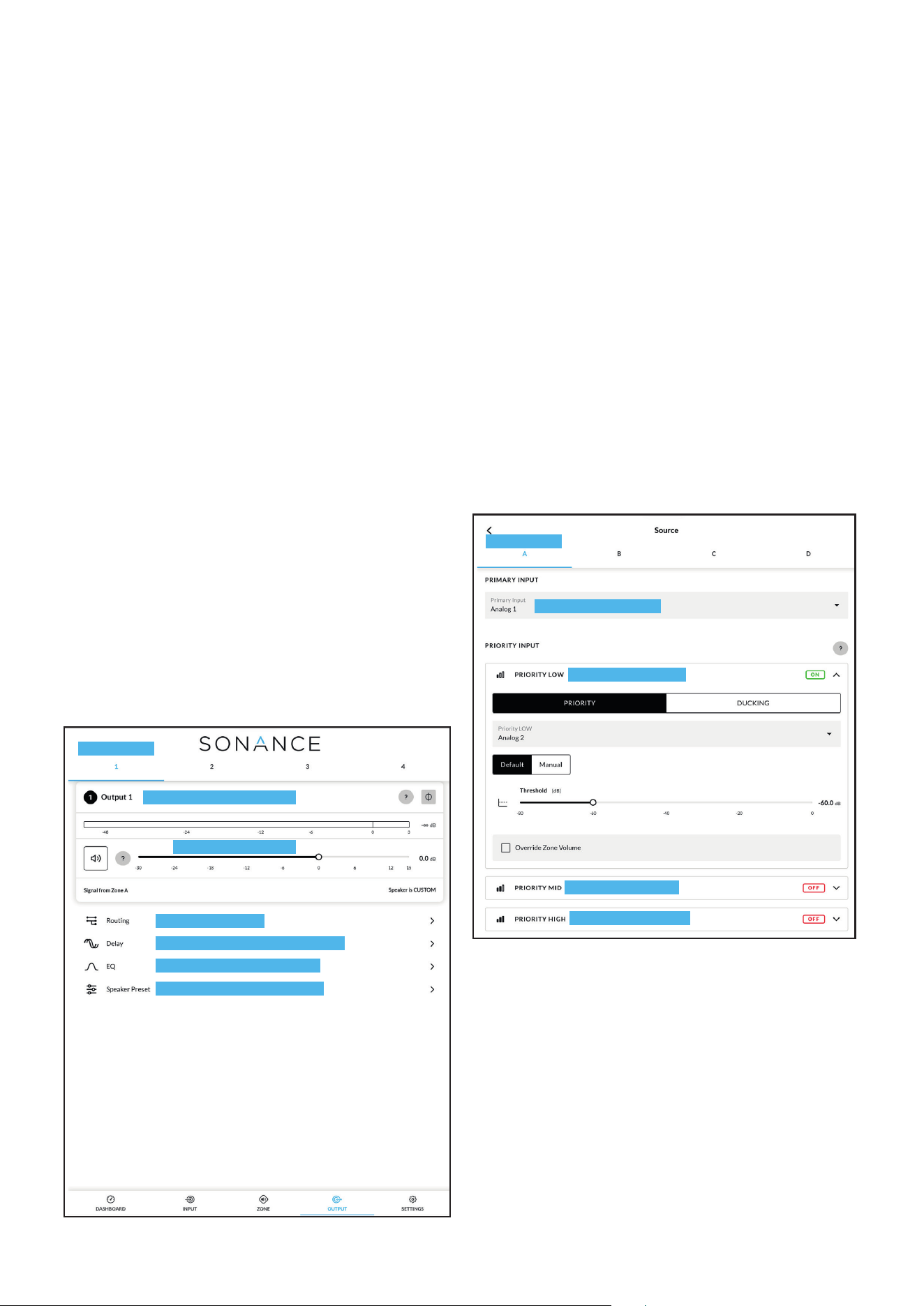
The Mix section enables input signals to be mixed and
routed to amplifier zones. The number of available
mixes is equal to the number of amplifier outputs.
Note: Mix inputs are muted by default with their level
adjustment sliders set to zero.
5.3 Configuration Menus
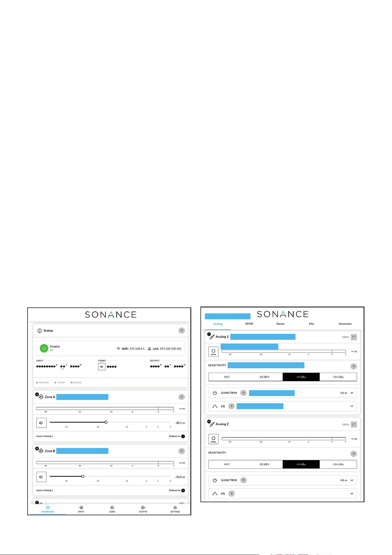
When the PowerZone Control interface is opened, the
Dashboard tab is displayed first.
The Dashboard provides an overview of amplifier
power and network status, input activity, zone status,
output activity, and available zones. It also provides
immediate access to zone volume controls.
The main interface tabs are Dashboard, Input, Zone,
Output, and Settings. The following sections provide
a general overview of the main interface tabs and key
configuration areas.
Note: The PowerZone Control interface includes
contextual tooltips that provide detailed guidance for
many settings and controls. Click or tap the circular
? icons in the interface to view additional information
about a setting or control.
Because available settings and software behavior may
change with firmware updates, use the in-app tooltips
as the primary reference for detailed configuration
guidance.
Diagram 6A
Configuration Dashboard display
Adjust zone volume
Adjust zone volume
Note: When adjusting input gain, the input level display should
remain green. If it displays red, the input gain should be reduced.
Diagram 6B
Input Tab display (two inputs only shown)
Input name - type to edit
Select mono or stereo
Select input sensitivity option
Adjust input gain
Open EQ window
Select input type
10
Diagram 6C
Input EQ display
Diagram 6D
Dante
®
Input display
Diagram 6E
Input Mix display
The Generator section provides a pink noise or sine
wave audio signal generator for audio system testing
and setup.
The inputs displayed in the Dante
®
input tab
(if available) will correspond to those configured and
enabled in the Dante
®
Controller macOS or Windows
application. If no inputs are displayed they must first be
enabled in Dante
®
Controller.
5.3.2 Zone Tab
The Zone tab enables installation zones to be defined,
named, configured, and controlled. Zones might
represent areas such as a room, bar, restaurant
area, lobby, patio, or other speaker zone within an
installation.
Available zones are selected using the zone identifiers
at the top of the display. The number of available zones
depends on the amplifier model, output configuration,
and whether zones are configured for mono or stereo
operation.
Select mix function
Select EDIT to apply required EQ
Mix name - type to edit
Adjust gain/trim
Configuration
Select Dante
®
input
11
Zone name - type to edit
Select zone
Select zone input
Configure zone volume options
Configure zone restrictions
Configure zone compressor
Adjust zone volume
Diagram 6F
Zone Tab display
Configuration
For each zone, the following controls and menus are
available:
• Zone name
• Mono/Stereo selection
• Zone level meter
• Zone volume control
• Source
• Volume
• Restrictions
• Compressor
Click or tap the zone name to rename the zone. Use
the mono/stereo control to define the zone format.
Use the zone volume control to adjust the listening
level for the selected zone.
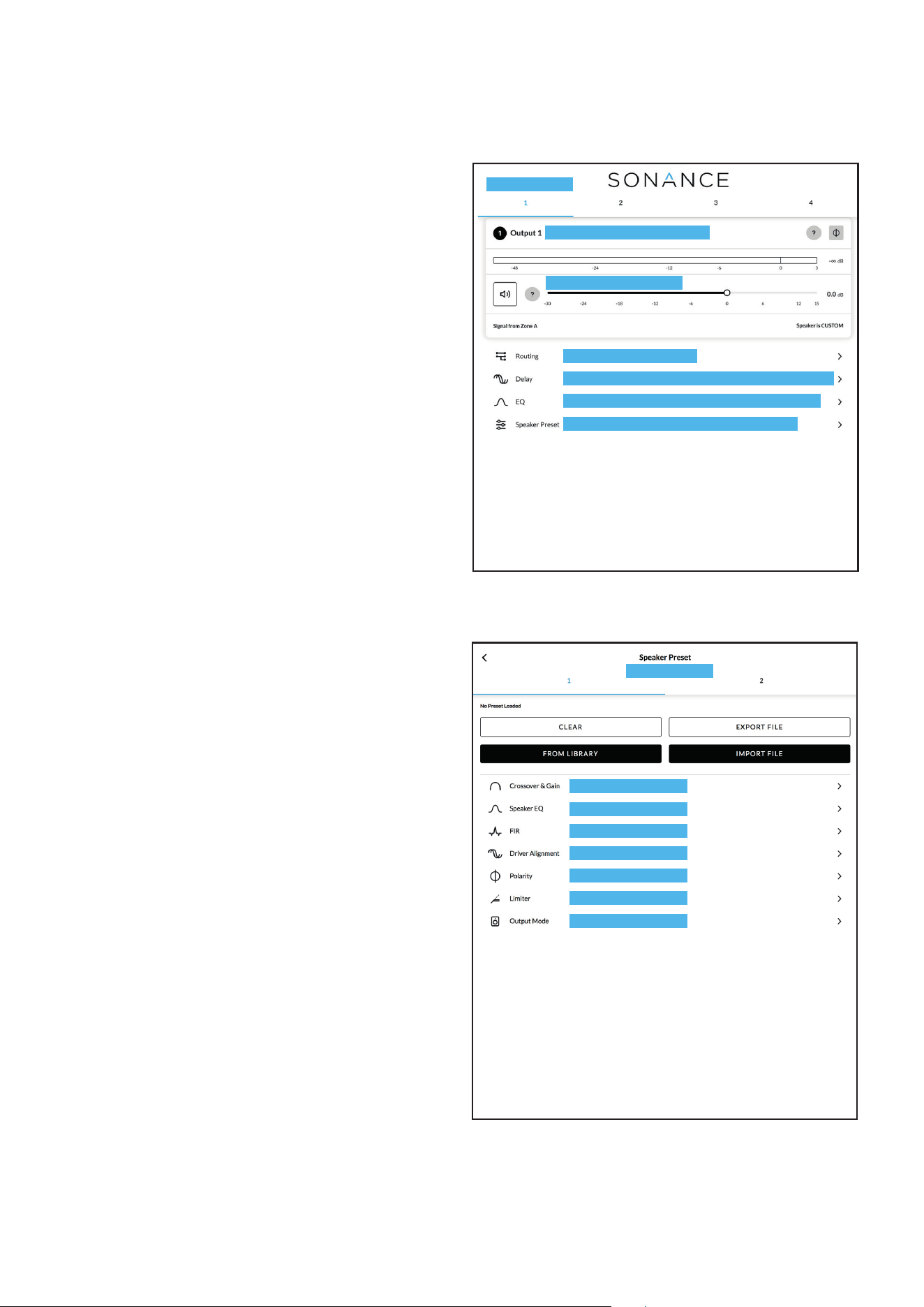
The Source menu enables inputs or input mixes to
be assigned to the selected zone. It also provides
access to source priority and ducking options where
supported.
The Volume menu provides additional zone volume
settings, including minimum and maximum volume
limits. External GPIO volume control can also be
assigned to individual zones where required. GPIO
configuration is available in the Settings tab.
The Restrictions menu enables specific inputs or input
mixes to be restricted from routing to selected zones.
Routing restrictions do not apply to priority inputs.
The Compressor menu enables signal compression to
be applied to individual zones. Compression can be
useful to reduce the level dierence between louder
and quieter audio material.
Note: Compression can be useful to reduce the volume
dierence between loud and quiet audio material.
The lower the compression threshold is set, the more
the dierence between loud and soft will be reduced.
The overall zone volume may need to be increased
when compression is used. The default compression
parameters are appropriate for most installations.
Select zone
Select Primary Input
Select Priority Low
Select Priority Mid
Select Priority High
Diagram 6G
Zone Source menu display
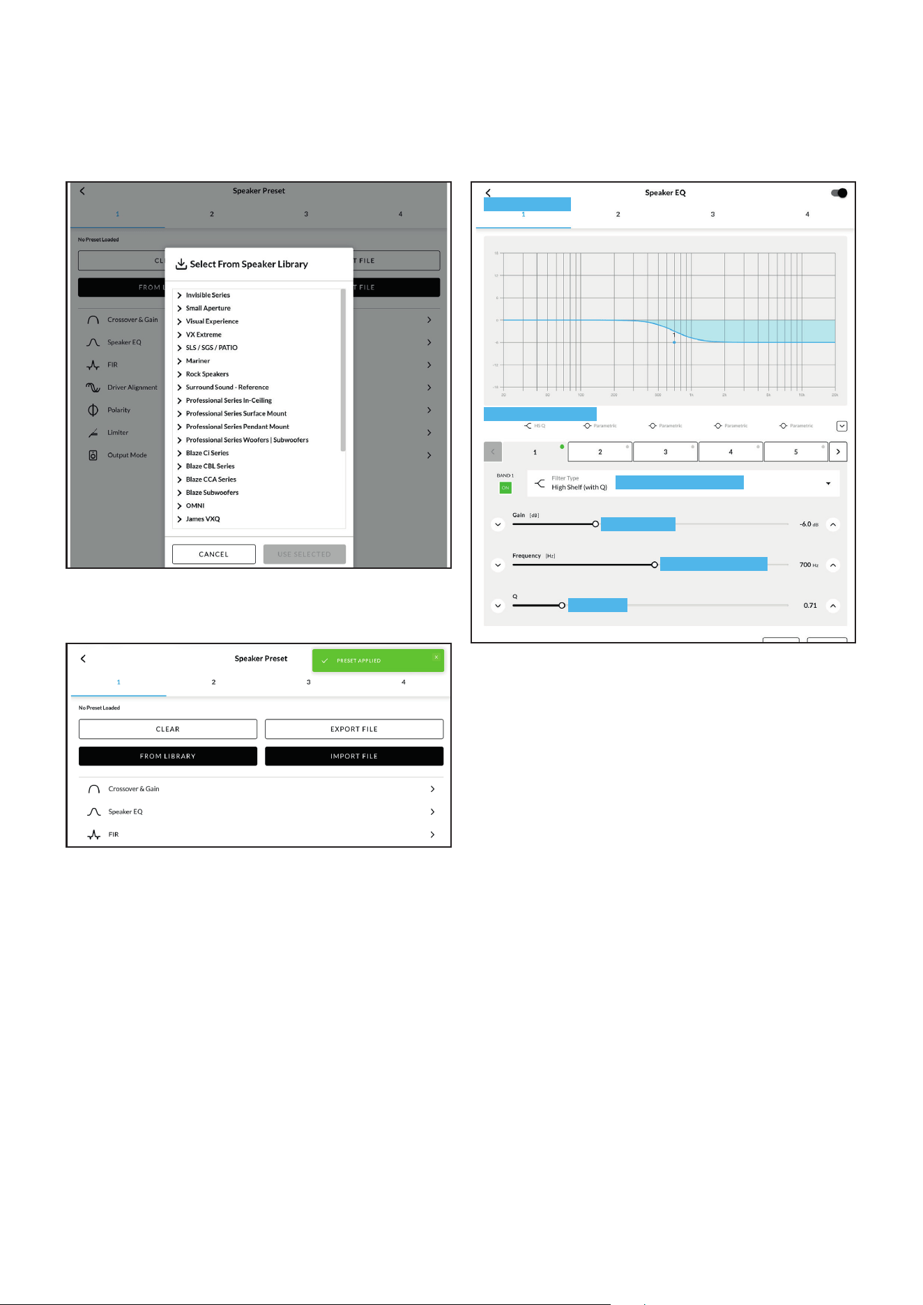
5.3.3 Output Tab
The Output tab enables amplifier outputs to be named,
routed to zones, adjusted, and configured. For each
output, the available menus include Routing, Delay, EQ,
and Speaker Preset.
Available outputs are selected using the output
identifiers at the top of the display. The number of
outputs available for configuration depends on the
amplifier model and output configuration.
12
Configuration
Diagram 5I
Speaker Preset Parameters
Select to configure
Select to configure
Select to configure
Select to configure
Select to configure
Select to configure
Select to configure
Select output
Diagram 5H
Output Tab display
Output name - type to edit
Select output
Enable and configure output delay if required
Define output routing
Enable and configure output EQ if required
Configure and manage speaker presets
Adjust gain if required
For each output, the following controls and menus are
available:
• Output name
• Output polarity
• Output level
• Routing
• Delay
• EQ
• Speaker Preset
Click or tap the output name to rename the output.
Use the output polarity control to reverse output
polarity if required. Use the output level control to
adjust output gain if required.
The Routing menu enables zones to be assigned to
amplifier outputs. For stereo zones, available routing
options may include left channel, right channel, or
summed mono.
The Delay menu enables delay to be applied to
individual amplifier outputs.
The EQ menu enables parametric equalization to
be applied to individual amplifier outputs. Equalizer
settings can be adjusted, copied, or cleared as required
The EQ menu also supports importing *REW (Room
EQ Wizard)* filter settings, allowing measurement-
based equalization filters to be imported into individual
amplifier outputs. Imported REW filters can be
reviewed and adjusted in the EQ menu as required.
The Speaker Preset menu enables speaker-specific
output parameters to be applied, imported, exported,
customized, or cleared. Speaker presets are discussed
in detail in Section 5.3.4.
The Sonance speaker preset library is available
by default and includes preset configurations for
supported Sonance loudspeakers. Additional speaker
presets may also be imported from preset files or
added to a speaker preset library where required.
Speaker presets may include crossover, EQ, FIR, driver
alignment, polarity, limiter, and output mode settings.
13
5.3.4 Speaker Preset Menu Parameters
The Speaker Preset menu provides access to speaker-
specific output processing and protection parameters.
Speaker presets can be used to apply recommended
settings for a specific loudspeaker or speaker system.
Speaker preset parameters may include:
• Crossover & Gain
• Speaker EQ
• FIR
• Driver Alignment
• Polarity
• Limiter
• Output Mode
Diagram 5J
Speaker Preset import file selection
Configuration
Diagram 5K
Speaker Preset applied
Speaker presets can be imported from a preset file,
selected from a speaker preset library, exported for
reuse, customized, or cleared from the selected output.
Imported speaker preset files may include locked
parameters. Locked parameters cannot be modified
unless an unlocked version of the preset is provided.
The Crossover & Gain menu enables high-pass or
low-pass crossover filters and gain adjustment to be
applied to individual amplifier outputs. These settings
are typically used to match the amplifier output to the
connected speaker type and system design.
The Speaker EQ menu enables parametric equalization
to be applied to individual amplifier outputs. Speaker
EQ can be used to apply loudspeaker correction or
system tuning filters.
The FIR menu enables FIR filter data to be imported
and applied to individual amplifier outputs. FIR
filters are typically generated using external speaker
measurement or tuning software.
Note: FIR coecient files in either .csv or .txt format can
be imported.
Diagram 5L
Speaker Preset parameter adjustment
Select output
Engage EQ bands
Select band function
Adjust gain
Adjust frequency
Adjust Q
14
Configuration
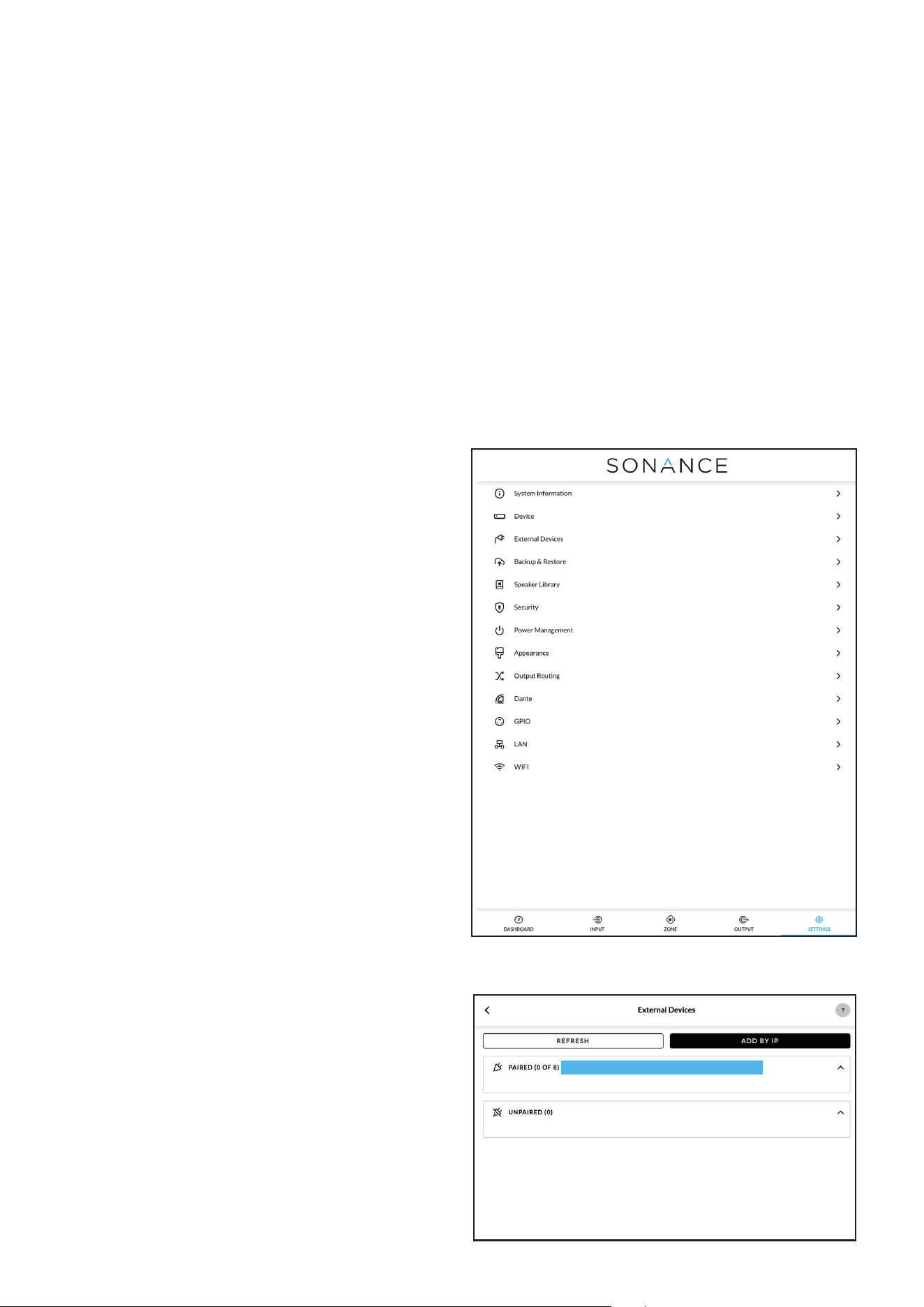
Diagram 5M
Settings Tab menu
Diagram 5N
The External Devices display
The Driver Alignment menu enables delay to be
applied to individual amplifier outputs for loudspeaker
driver or system alignment.
The Polarity menu enables the polarity of individual
amplifier outputs to be reversed.
The Limiter menu enables output limiting to be
configured for individual amplifier outputs. Limiter
settings can be used to help protect connected
loudspeakers and maintain system performance.
The Output Mode menu enables individual amplifier
outputs to be switched o or configured for the
connected speaker type. Available output modes
include O, Hi-Z - 70V, Hi-Z - 100V, and Lo-Z.
The Output Filter setting enables a high-pass filter to
be applied to the selected output. A high-pass filter is
recommended for high-impedance speaker systems
to reduce low-frequency content that may cause
transformer saturation or distortion.
5.3.5 Settings Tab
The Settings tab provides access to amplifier
information, system configuration, network settings,
security options, backup and restore functions, and
other device-level settings.
The Settings tab includes the following menus:
• System Information
• Device
• External Devices
• Backup & Restore
• Speaker Library
• Security
• Power Management
• Appearance
• Output Routing
• GPIO
• LAN
• WiFi
The System Information menu provides editable fields
for recording installation information, including device
name, venue name, customer name, etc.
The Device menu displays amplifier-specific
information. The Device menu also provides access
to the “Find Me” function, which illuminates the front
panel indicators to help identify the amplifier, and also
the firmware “Update” function.
The External Devices menu enables compatible
external devices or control interfaces to be discovered,
paired, and managed. Devices can be refreshed, paired
from the discovered-device list, or added manually by
IP address where supported.
The Backup & Restore menu enables the amplifier
configuration to be saved to a file or restored from a
previously saved file. This menu also provides access to
device restart and factory reset functions.
Warning: A factory reset permanently erases all
configuration data from the amplifier.
External device - tap to configure
15
Configuration
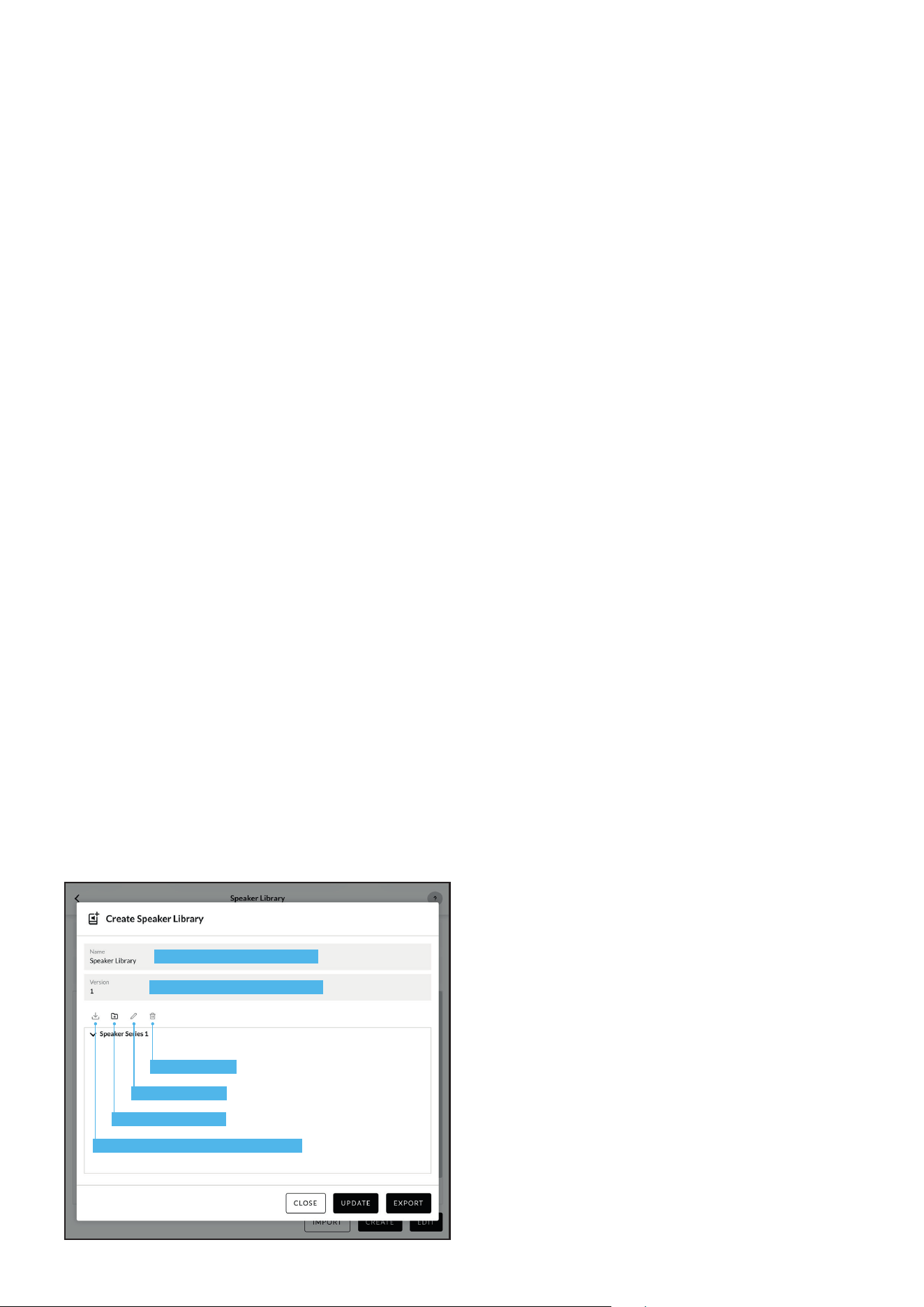
Diagram 5O
Speaker Library Creation and Management
Library name - type to edit
Library version - type to edit
Import preset data (.zcp) to library
Create new library
Rename library
Delete library
The Speaker Library menu provides access to available
speaker preset libraries. The default Sonance speaker
library is included and provides preset configurations
for supported Sonance, Blaze, and James loudspeakers.
Additional libraries may be imported, created, or edited
where required.
The Security menu enables password protection
and user control options. Password protection
helps prevent unauthorized access to the amplifier
configuration interface. User control can be used to
limit access to selected zone controls.
The Power Management menu enables amplifier
standby, wake, and power behavior to be configured.
The Appearance menu enables the PowerZone Control
interface to be switched between light mode and dark
mode.
The Output Routing menu enables specified inputs or
zones to be routed to the amplifier’s digital outputs
where supported.
The GPIO menu enables the multi-purpose GPIO pins
to be configured for supported functions such as
standby, mute, trigger, and external volume control.
GPIO wiring and connection information is provided in
Section 5.5.
The LAN menu enables wired network settings to be
configured.
The WiFi menu enables wireless network settings to be
configured.
5.4 Setup and Signal Routing
PowerZone Connect PRO amplifiers provide flexible
signal routing for a wide range of installations. Inputs
can be assigned to zones, and zones can then be
routed to amplifier outputs. This allows dierent source
signals to be routed to dierent areas of an installation,
or the same source signal to be routed to multiple
zones.
Signal routing is configured in three main steps:
1. Configure the required input sources in the Input tab.
2. Configure zones and assign sources in the Zone tab.
3. Assign zones to amplifier outputs in the Output tab.
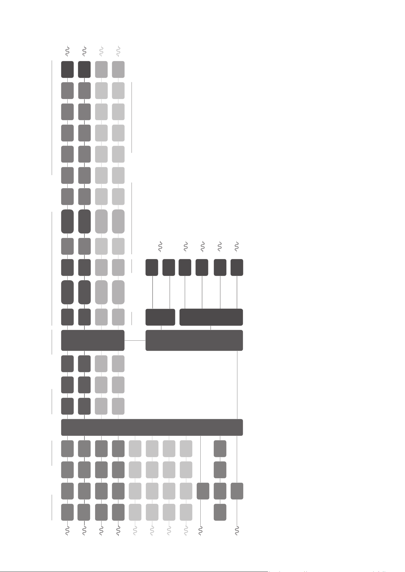
A general signal flow schematic is illustrated in
Diagram 5P.
5.4.1 Input Setup
Open the Input tab to configure the required input
sources.
For each input, confirm or configure the input name,
mono/stereo setting, input sensitivity, high-pass filter,
gain/trim, and input EQ as required.
Select an input sensitivity setting appropriate for the
connected source equipment. Generally, +4 dBu or
+14 dBu are appropriate for professional audio source
equipment, while -10 dBV is appropriate for consumer
audio source equipment. The MIC setting provides
the higher sensitivity required for microphone-level
sources.
Note: Only dynamic microphones are suitable for
connection. Phantom power for condenser microphones
is not provided.
Adjust input gain only as required after selecting
the appropriate input sensitivity. If the input meter
indicates clipping or limiting, reduce the input gain or
select a less sensitive input setting.
Lastly, if necessary, adjust the input EQ using the
5-band equalizer.
16
Configuration
Diagram 5P
Signal Flow Schematic
(four output amplifier)
Analog
SPDIF In
(stereo)
Signal
generator
Zone processing A-D
Speaker presets
Source
selector
Output processing 1-4
Room/posion/system
HPF LPF
Dante 1-4
Input processing
Analog 3
Output
Matrix
Analog 2
Analog 1
Input Gain
Input Gain
Input Gain
Analog 4
AMP CH1
AMP CH2
Compressor
10-band EQDelay
Compressor
Delay
Driver
alignment
Crossover
& Gain
Limiter
Driver
alignment
Limiter
FIR
FIR
Polarity
Polarity
Level
control
Level
control
HPF
HPF
HPF
HPF
AMP Out 1
AMP Out 2
HPF
HPF
5-band EQ
5-band EQ
5-band EQ
5-band EQ
Priority
override/
Ducker
Priority
override/
Ducker
SPDIF Out
(stereo)
Gain
Gain
Gain
Gain
Gain
Gain
Dante Out 1
Dante Out 2
Dante Out 3
Dante Out 4
S/PDIF
roung
selector
Dante
roung
selector
8 Ω load
70V
100V
8 Ω load
70V
100V
Analog 7
Analog 6
Analog 5
Analog 8
Compressor
Compressor
Level
control
Level
control
HPF
HPF
HPF
HPF
5-band EQ
5-band EQ
5-band EQ
5-band EQ
Priority
override/
Ducker
Priority
override/
Ducker
AMP CH3
AMP CH4
Delay
Delay
Driver
alignment
Limiter
Driver
alignment
Limiter
FIR
FIR
Polarity
Polarity
AMP Out 3
AMP Out 4
HPF
HPF
8 Ω load
70V
100V
8 Ω load
70V
100V
10-band EQ
10-band EQ
15-band EQ
15-band EQ
Input
Sensivity
Input
Sensivity
Input
Sensivity
Input
Sensivity
Input Gain
Input Gain
Input Gain
Input Gain
Gain
Gain
Crossover
& Gain
Crossover
& Gain
10-band EQ
15-band EQ
15-band EQ
Input
Sensivity
Input
Sensivity
Input
Sensivity
Input
Sensivity
Input Gain
Input Gain
L/R
Input Gain
1-4
Input Gain
Gain
Gain
Output
roung
Crossover
& Gain
17
Configuration
5.4.2 Zone Setup & Routing
Open the Zone tab to configure zones and assign
sources.
Select the zone to be configured using the zone
identifiers at the top of the display. The number of
zones available depends on the amplifier model and
configuration.
For each zone, configure the zone name, mono/
stereo setting, source assignment, volume settings,
restrictions, and compressor settings as required.
Use the Source menu to assign an input or input mix to
the selected zone. Selecting a stereo input for a mono
zone will automatically sum the stereo channels to
mono.
5.4.3 Output Setup and Routing
Open the Output tab to assign zones to amplifier
outputs.
Select the output to be configured using the output
identifiers at the top of the display. For each output,
configure the output name, polarity, output level,
routing, delay, EQ, speaker preset, and output mode as
required.
Use the Routing menu to assign a zone to the selected
output. For stereo zones, available routing options may
include left channel, right channel, or summed mono.
Use the Speaker Preset menu to apply the appropriate
output mode and speaker-specific processing for the
connected speaker type.
Caution: Lo-Z output mode is intended for speakers
with a nominal impedance of 4 ohms or higher.
Connecting speakers or speaker loads below 4 ohms
may cause the amplifier to enter protection mode or
may result in reduced performance.
5.5 GPIO Setup and Connection
PowerZone Connect PRO amplifiers provide a
configurable GPIO connector for external control and
trigger functions. GPIO functions may include standby,
mute, 12V trigger input, 12V trigger output, and
external volume control, depending on the selected pin
configuration.
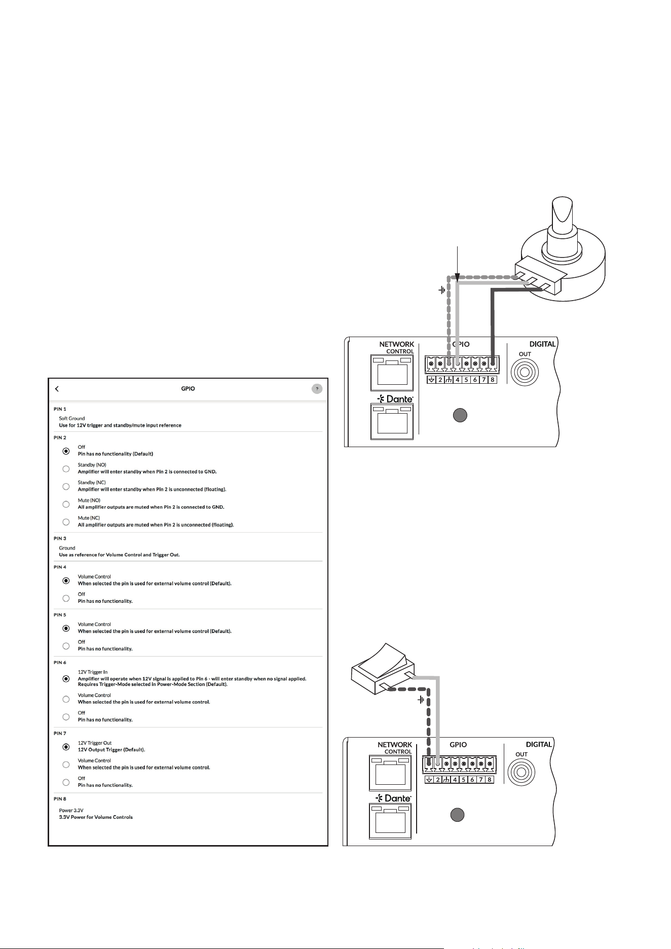
GPIO pin functions are configured in the Settings
> GPIO menu. The GPIO menu displays each pin,
its available functions, and the currently selected
configuration. Refer to the on-screen descriptions and
tooltips when configuring GPIO behavior.
Caution: The GPIO connector must not be used for
any unintended purpose. Incorrect GPIO wiring or
configuration may damage the amplifier or connected
equipment.
Caution: Use shielded cable when connecting external
standby switches, mute switches, trigger wiring, or
potentiometers via GPIO.
The GPIO connector includes ground reference pins,
configurable control pins, and a 3.3V supply for external
volume controls.
* Pin 1 provides a soft ground reference for 12V trigger
and standby/mute input functions.
* Pin 2 can be configured for standby or mute control,
normally open or normally closed.
* Pin 3 provides a ground reference for external volume
control and trigger output functions.
* Pins 4 and 5 can be individually configured for external
volume control.
*Pin 6 and 7 can individually be configured for 12V trigger
input, external volume control, or no function.
*Pin 8 provides 3.3V power for external volume controls.
18
Configuration
Diagram 5S
Connections for remote
standby/mute switch via
GPIO.
Note: Diagram 6E illustrates
use of the GPIO connector.
Ground
Standby/Mute
Diagram 5R
Potentiometer connections for remote
volume control via GPIO.
Note: Diagram 6E illustrates
use of the GPIO connector.
Ground
+3V3
Potentiometer
(>10kΩ)
Connect Wiper to
Pin 4, 5, 6 or 7.
Switch open (NO) or
closed (NC) toggles
Standby or Mute
depending on options
selected in the GPIO
Settings Menu
Diagram 5Q
GPIO Settings Menu
Note: GPIO Pin 1 and Pin 3 both provide ground
connections. Pin 1 is connected directly to the amplifier
chassis. Pin 3 is connected to the chassis through a 220
ohm resistor. The soft ground connection of Pin 3 is
potentially useful for managing ground loops that may
cause audible hum.
Note: GPIO Pin 8 has a low output impedance and can
supply a maximum current of 10 mA.
External volume control can be implemented using a
potentiometer connected to the appropriate GPIO pins.
Standby or mute control can be implemented using an
external switch connected to the configured GPIO pin
and ground reference. Refer to Diagrams 5R and 5S for
example wiring.

19
Connections
6. Connections
PowerZone Connect PRO amplifier rear panel
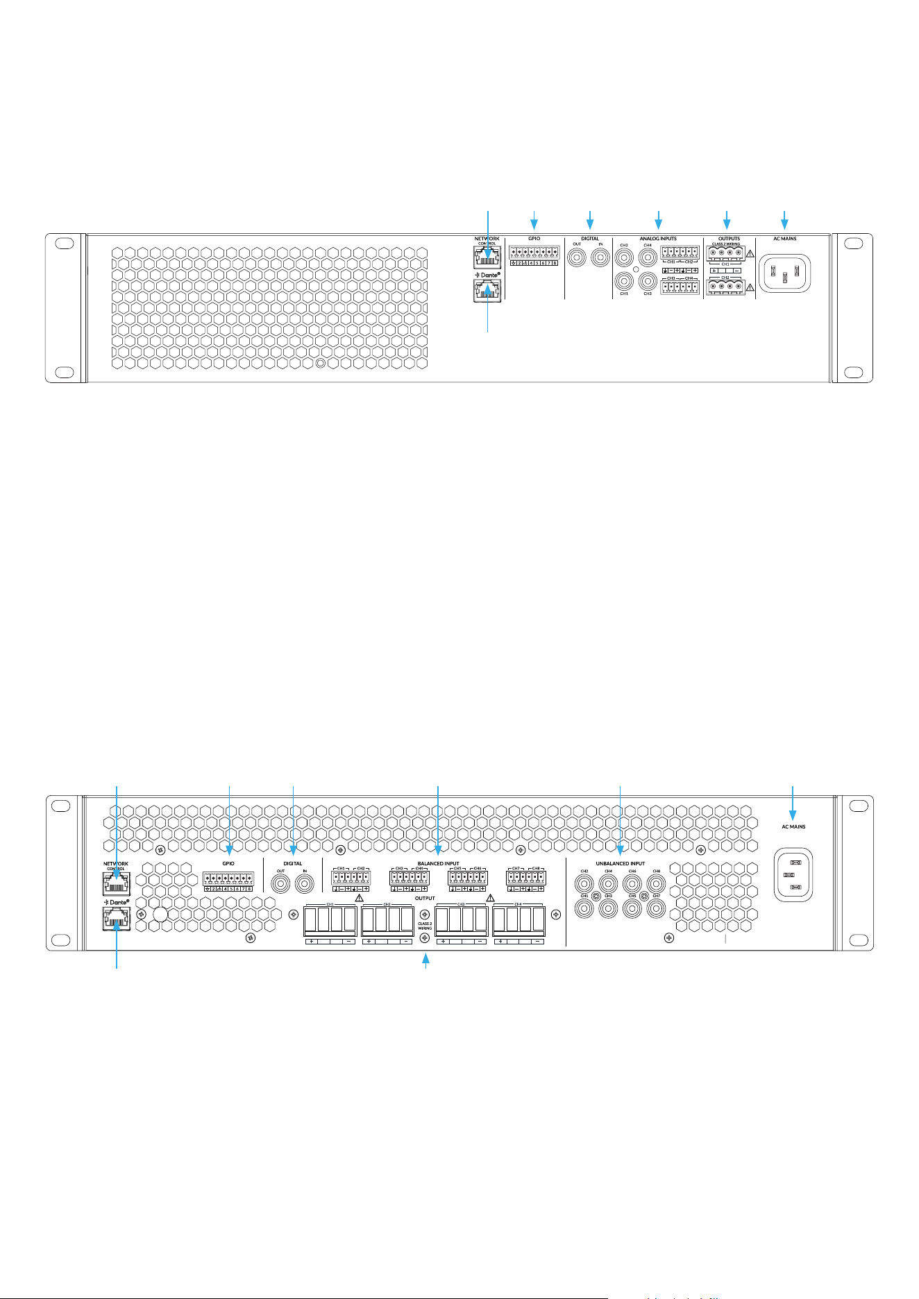
connections are illustrated in Diagrams 6A and 6B.
6.1 Mains Power Connection
PowerZone Connect PRO amplifiers incorporate a
power factor corrected universal power supply and
can be used with mains input voltage from 100V AC to
240V AC, 50/60Hz. Use the mains cable supplied with
the amplifier.
PowerZone Connect PRO 2U amplifiers incorporate a
front panel mounted power button. Press the button
once to switch the amplifier on or o. Ensure that all
signal, GPIO and output connections are made before
connecting the amplifier to mains power.
6.2 Input Connection
All PowerZone Connect PRO amplifier models provide
four (or eight) balanced and unbalanced analog audio
inputs and a stereo S/PDIF digital audio input. Any
input channel can be routed to any output channel.
Input routing options can be configured via the
PowerZone Control interface. See Section 5 of this
manual.
Analog Inputs
PowerZone Connect PRO analog inputs are of line level
format with a default input sensitivity of +4dBu (full
output voltage swing/sensitivity) in all output modes.
Input signal levels up to +24dBu can be handled with-
out input clipping. Input sensitivity options can be set
via the PowerZone Control interface. See Section 5 of
this manual.
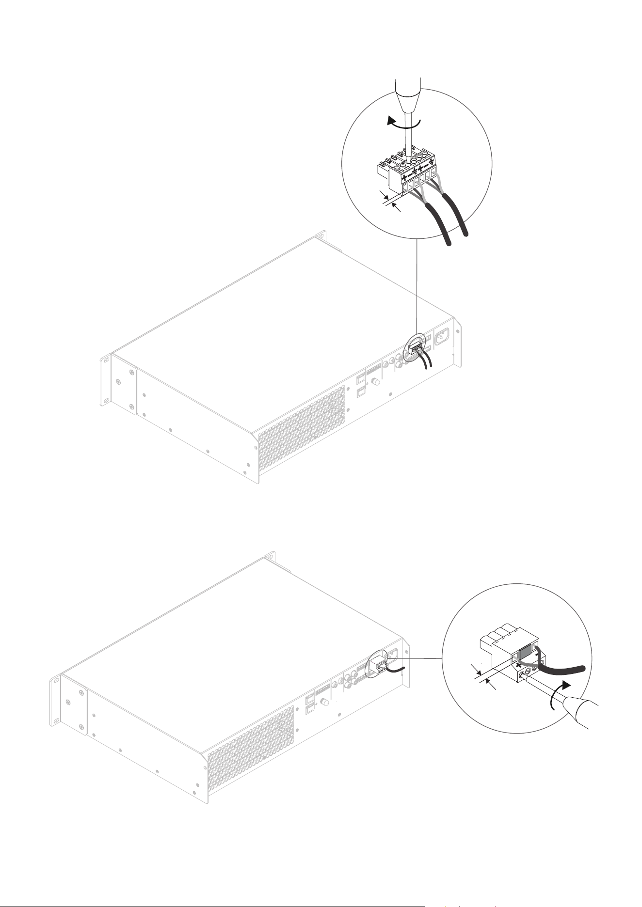
Balanced input connections to the amplifiers are made
via male ‘Euro Block’ connectors. Connecting cables to
the supplied female input connectors is illustrated in
Diagram 6C.
Unbalanced input connections to the amplifiers are
made via RCA phono sockets connected in parallel
with the balanced inputs.
Digital Outputs
PowerZone Connect PRO S/PDIF stereo digital audio
output connections are made via a single RCA Phono
socket. The S/PDIF output signal can be routed from
any input or zone and is intended to be used for daisy-
chaining PowerZone Connect PRO amplifiers.
Note: See the Output Routing paragraphs of
Section 5.3.3 for more information on Digital Output
configuration.
Note: 75Ω RCA Phono cables specifically intended
for digital audio should always be used for S/PDIF
connections. Standard Phono cables can be used but
may not result in optimal performance.
Note: The S/PDIF output level is by default set at -10dB
to reduce the possibility of downstream input clipping.
6.3 Output Connections
Output connections from the amplifiers are achieved
via male ‘Euro Block’ connectors. Ensure that speaker
connection polarity is correct throughout the
installation.
Supplied plugs are provided to block the center two
positions of the 4-pin output connector, helping
prevent accidental misconnections during installation.
For Hi-Z and Lo-Z speaker connections, positive (+)
amplifier terminals should always be connected to
positive speaker terminals and negative (–) amplifier
terminals always connected to negative speaker
terminals.
Output mode options (Hi-Z or Lo-Z) can be configured
via the PowerZone Control interface.
Note: see the Speaker Preset Menu Parameters of
Section 5.3.4 for more information on selecting Hi-Z or
Lo-Z output modes.
20
5. Audio Inputs:
Balanced: Euroblock
Unbalanced: RCA Phono
6. Configurable Speaker Outputs
7. Power Input
Connections
Diagram 6B
PowerZone Connect PRO
Amplifier rear panel connections.
1. Network Control
2. Dante
®
(optional)
3. Configurable GPIO
4. Configurable S/PDIF Audio I/O
5. Balanced Audio Inputs: Euroblock
6. Unbalanced Audio Inputs: RCA Phono
7. Configurable Speaker Outputs
8. Power Input
1. Network Control
2. Dante
®
(optional)
3. Configurable GPIO
4. Configurable S/PDIF Audio I/O
Diagram 6A
PowerZone Connect PRO
Amplifier rear panel connections.
1 3 4 5 6 8
2 7
*Product shown as an example is PowerZone
®
Connect PRO 4000.4D
1
2
3 4 5 6 7
*Product shown as an example is PowerZone
®
Connect PRO 2000.2D
21
Connections
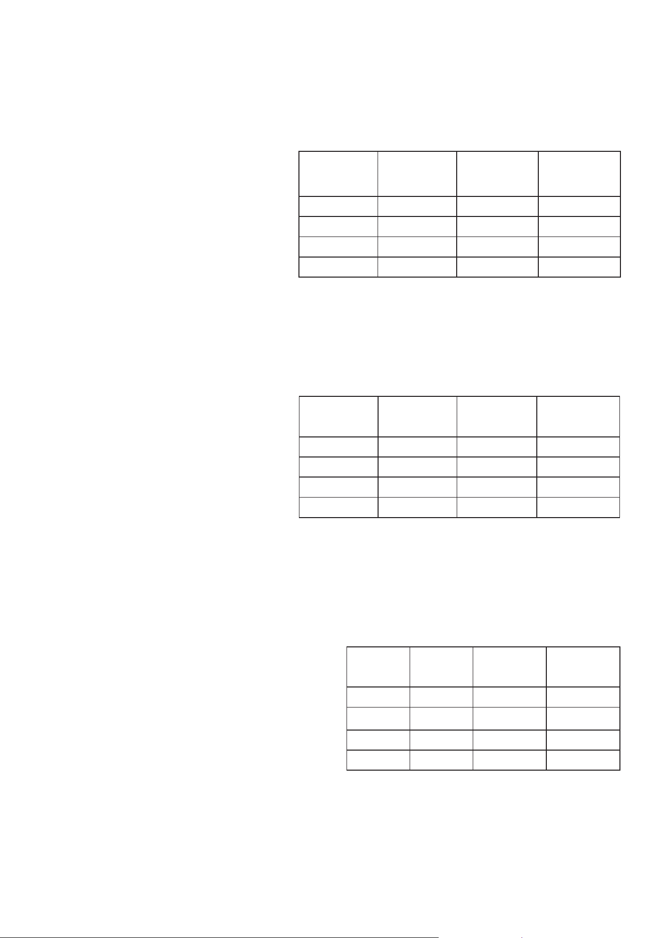
Cable Gauge Table
Lo-Z installations, 0.5dB attenuation. 4 & 8 Ω loads
Cable Gauge Table
70V Hi-Z installations, 1.0dB attenuation
20 speakers evenly distributed
Cable Gauge Table
100V Hi-Z installations, 1.0dB attenuation
20 speakers evenly distributed
Cable Cross
Section
(mm
2
)
Cable
Gauge
(AWG)
Max Cable
Length (m),
(4 Ω load)
Max Cable
Length (m),
(8 Ω load)
0.75 ≈18 5 10
1.5 ≈16 10 20
2.5 ≈14 17 35
4.0 ≈12 28 55
Cable Cross
Section
(mm
2
)
Cable Gauge
(AWG)
Max Cable
Length (m),
(150 W/channel)
Max Cable
Length (m),
(300 W/channel)
0.75 ≈18 90 45
1.5 ≈16 180 90
2.0 ≈14 <250 150
3.5 ≈12 <250 <250
Cable Cross
Section
(mm
2
)
Cable Gauge
(AWG)
Max Cable
Length (m),
(150 W/channel)
Max Cable
Length (m),
(300 W/channel)
0.75 ≈18 190 90
1.5 ≈16 <250 180
2.0 ≈14 <250 <250
3.5 ≈12 <250 <250
Note: Cable lengths should not exceed 250m.
Note: Cable lengths should not exceed 250m.
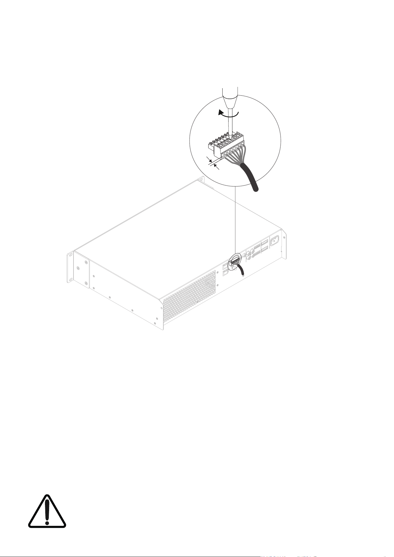
Connecting cables to the supplied female
output connector is illustrated in Diagram 6D.
6.4 Speaker Cable Gauge
The PowerZone Connect PRO speaker
connection cable gauge should be chosen
appropriately to reflect the type of installation.
The adjacent tables specify the appropriate
cable gauge for dierent installation types,
cable lengths, and allowable cable loss.
6.5 GPIO Connections
If any PowerZone Connect PRO GPIO
functionality is required, cables will need to
be connected to the supplied GPIO connector.
Connecting cables to the GPIO connector is
illustrated in Diagrams 6E.
6.6 Network Connections
PowerZone Control
PowerZone Connect PRO amplifiers are TCP/
IP network devices that can be configured
either through the PowerZone Control web
app or via the PowerZone Control Center
desktop application. Wired (Ethernet) and
wireless (Wi-Fi) connection options are
available. Connecting PowerZone Connect PRO
amplifiers to a TCP/IP network is described in
Section 5 of this manual. If a wired connection
is used, connect an Ethernet cable to the
amplifier rear panel Network Control socket.
Audinate Dante
®
PowerZone Connect PRO amplifiers are
optionally compatible with Audinate Dante
®
audio over IP (AoIP) networks and installations.
Connect to a Dante
®
network via the amplifier
rear panel Dante
®
socket and configure the
network as required using the Audinate Dante
®
Controller macOS and Windows application
available for download from:
www.audinate.com/products/software/dante-
controller.
22
5 mm
Hi-Z & Lo-Z Mode
5 mm
Diagram 6C
Balanced analog
input cable connections.
Diagram 6D
Output cable connections.
Note: Four channel amplifiers
employ a larger output connector.
Connections
23
5 mm
Diagram 6E
GPIO cable connections.
Connections
The exclamation point printed next to the output terminals of the amplifiers is, in addition to the
CLASS 2 WIRING text, intended to alert users to the risk of hazardous voltages. Output connectors
that could pose a risk are marked with the exclamation point. Do not touch the output terminals
while the amplifier is switched on. Make all connections with the amplifier switched off.

24
Note: If the front panel indicators are repeatedly lighting
up one after another from top to bottom, the amplifier
has the “Find Me” mode enabled.
Operation
7. Operation
Once all connections have been made and
configuration options selected, PowerZone Connect
PRO amplifiers are ready for use. If an input signal
above -60dB is present on any input, the front panel
Input and Standby indicators will illuminate green to
indicate normal amplifier operation. Audio will be heard
from any connected speakers.
Note: PowerZone Connect PRO amplifiers will not
switch on from Standby Mode unless an input signal
is present, a network ‘ON’ command is received, or an
external standby switch (or 12V trigger) is operated.
Standby behaviour can be configured via the Power
Management menu of the Settings Tab.
Amplifier outputs will mute if no input signal is
present for 5 minutes, and the amplifier will switch
automatically to Standby Mode if no signal is present
on any input for more than 15 minutes. Alternative
standby and mute delay times can be selected via
the Settings Tab. Amplifier cooling fan speed is
temperature controlled. The fan will switch o when
the amplifier enters standby mode.
7.1 Front Panel Indicators
PowerZone Connect PRO amplifier front panel indi-
cators illuminate to indicate the following operational
states:
Status: O – Mains power disconnected.
Green – Amplifier operational.
Pulse Green – Standby Mode.
Amber – GPIO triggered Standby Mode
Input: O – No input signal present.
Green – Signal present on one or more inputs.
Amber – Signal limiting/clipping on one or
more inputs.
Output: O – No output signal present.
Green – Signal present on one or more outputs.
Amber – Signal limiting/clipping on one or
more outputs.
Red – One or more channel pair is in
overload/protection mode.
Network: O – No Ethernet network detected.
Green – Ethernet network detected.
Wi-Fi: O – Wi-Fi disabled.
Green – Wi-Fi enabled.
7.2 Factory Reset
PowerZone Connect PRO amplifiers can be returned to
their default settings via either the Control Web App
Settings Tab or through the front panel power button.
To reset the amplifier using the front panel power
button, follow the steps below:
• Disconnect the amplifier from mains power.
• Press and hold the front panel power button while
simultaneously reconnecting mains power.
• Continue to hold the front panel power button for 3
to 5 seconds as the amplifier restarts.
The amplifier will restart with all settings at their
default state. Any previously configured settings will be
deleted.
25
Specifications
Typical Thermal Performance
PowerZone
Connect PRO
Load
(Ohms)
Power In
(W)
Power Out
(W)
Eciency
(%)
Thermal Loss
(W)
Thermal Loss
(BTU)
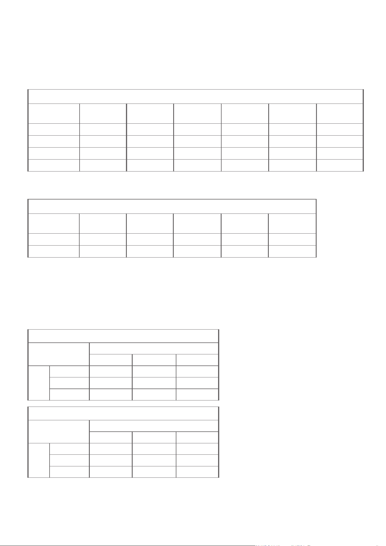
2000.2/2000.2D 4 378 250 66.6 128 436
4000.4/4000.4D 4 758 500 66.0 258 880
2000.2/2000.2D 8 346 250 72.2 96 327
4000.4/4000.4D 8 689 500 72.6 189 644
Standby and Idle
PowerZone
Connect PRO
Standby
(mW)
Idle @ 120V
(W)
Idle @ 120V
(BTU)
Idle @ 230V
(W)
Idle @ 230V
(BTU)
2000.2/2000.2D <500* 23.2 79 25.6 87
4000.4/4000.4D <500* 43.0 147 48.0 164
Power Eciency Data
The following table describes the eciency and power performance of PowerZone Connect PRO amplifiers.
The table also includes the derived thermal losses.
2 Channel Amplifiers
OUT
Analogue S/PDIF Dante
®
*
IN
Analogue 1177µS 458µS 1520µS
S/PDIF 1833µS 1104µS 2166µS
Dante
®
* 1895µS 1166µS 2125µS
4 Channel Amplifiers
OUT
Analogue S/PDIF Dante
®
*
IN
Analogue 1307µS 600µS 1662µS
S/PDIF 1955µS 1250µS 2312µS
Dante
®
* 2017µS 1312µS 2125µS
Propagation Delay Data
The following tables describes the input/output latency performance of PowerZone Connect PRO
amplifiers.
*Dante
®
network latency not included.
Note: Dante
®
latency is measured in a Dante
®
to Dante
®
connection setup. The propagation
delay is both measured from both analog
inputs and digital inputs. The total delay of:
Amp1 SPDIF input to Dante
®
out -> Amp2
Dante
®
input to SPDIF output is 4333 µs.
Out of this the network latency accounts for
1000 µs and the ASCRs accounts for 3 x 1000
µs. Out of the final 333 µs seconds, the DSP
accounts for roughly 208 µs, leaving 125 µs
for the Dante
®
chip processing. For this test
the Dante
®
process occurs twice resulting in a
62,49 µs delay per Dante
®
transmission.
*As per compliance to ErP
26
Specifications
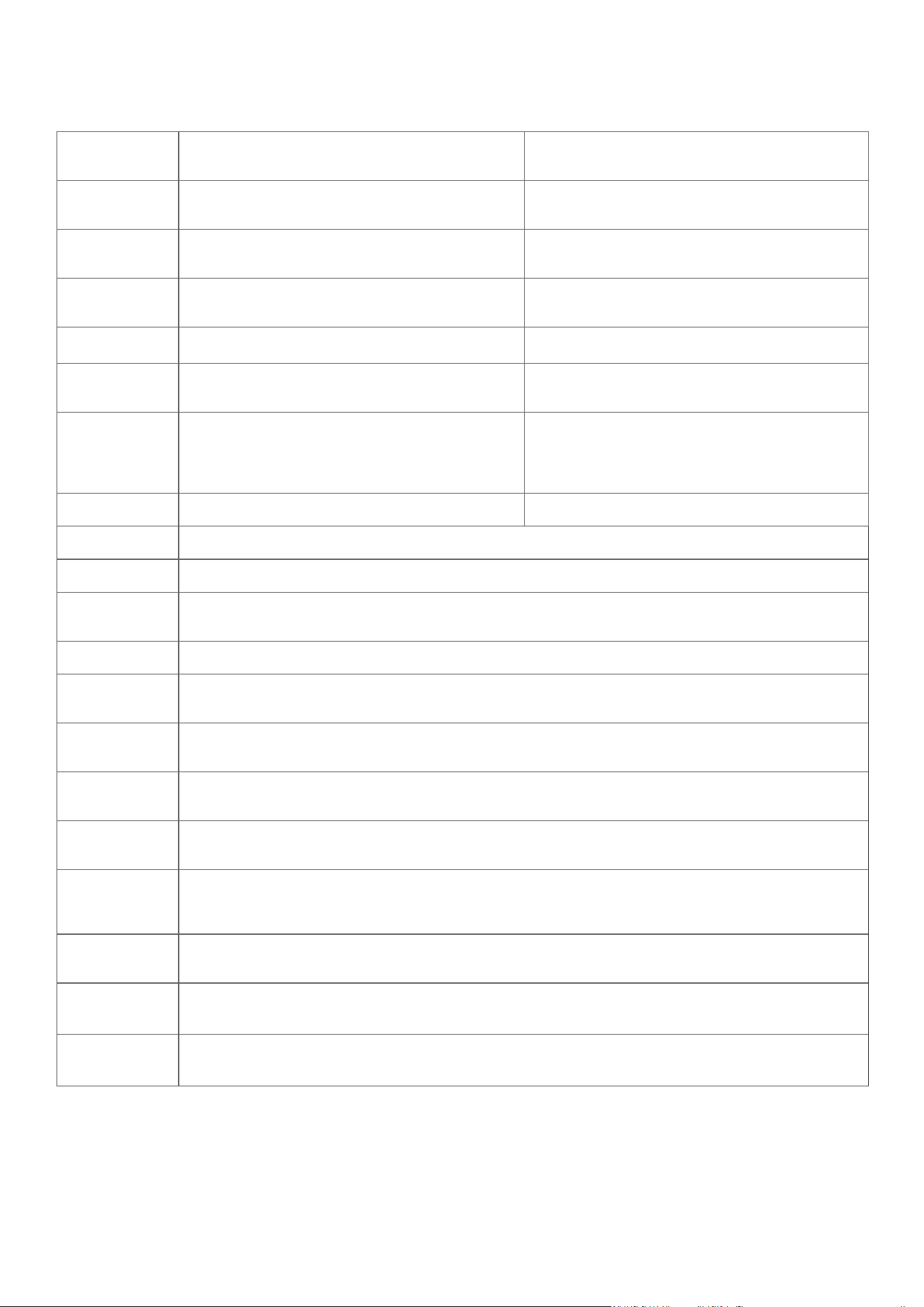
Model
PowerZone Connect PRO
2000.2/2000.2D
PowerZone Connect PRO
4000.4/4000.4D
Total System
Power
2000 W 4000 W
Output Power @
70/100 V
2 x 1000 W 4 x 1000 W
Output Power @
4/8 Ω
2 x 1000 W 4 x 1000 W
Powersharing N/A N/A
Power
Consumption
700 W 1400 W
Dimensions
(HxWxD)
88 x 440 x 320 mm
(3.5 x 17.3 x 12.6) in
88 x 440 x 414 mm
(3.5 x 17.3 x 16.3) in
Weight 7.4 kg (16.3 lbs) 11.6 kg (25.6 lbs)
Output Circuitry UMAC™ Class D - full bandwidth PWM modulator with ultra-low distortion
Output Voltage*
90 Vrms - 70 / 100 V (Hi-Z)
Signal-to-Noise
Ratio
>106 dB (A-weighted, 20 Hz - 20 kHz, 8 Ω load)
THD+N (typical) < 0.05% (20 Hz - 20 kHz, 8 Ω load, 3 dB below rated power)
Frequency
Response
20 Hz - 20 kHz (+0/-0.5 dB), 8 Ω load, 3 dB below rated power
Protection
Circuits
Short circuit, DC, Undervoltage, Temperature, Overload protection
Power Supply
UREC™ universal mains switch mode power supply with Power Factor Correction (PFC)
and standby converter
Operating
temperature
0 - 40° C
Operating
Voltage/
Frequency
Universal Mains, 100 V - 240 V, 50 Hz - 60 Hz
Standby
Consumption
< 0.5 W
Accessories
2 Rack ears, 4 adhesive feet, input/output connection plugs (included)
Rack rear support hardware (included w/ 4000.4/4000.4D)
Audinate Dante
®
Compatibility
Audinate Dante
®
AoIP compatibility: Ultimo Chip 4x4, 2 flows rx/tx
(PowerZone
®
Connect PRO 2000.2D/4000.4D only)
* Output voltage is managed according to selected output mode and load.

©2026 Sonance. All rights reserved. Sonance and PowerZone are registered trademarks of Dana Innovations. Due to continuous product improvement, all features
and specifications are subject to change without notice. For the latest Sonance product specification information visit our website at www.sonance.com.
SONANCE • 991 Calle Amanecer • San Clemente, CA 92673 USA • Phone: (949) 492-7777 Technical Support: (949) 492-7777 • www.sonance.com •
Rev A 23/06/2026
WARRANTY
LIMITED FIVE (5) YEAR WARRANTY
Sonance warrants to the first end-user purchaser that this Sonance-brand product (“Product”), when purchased
from an authorized Sonance Dealer/Distributor, will be free from defective workmanship and materials for the
period stated below. Sonance will at its option and expense during the warranty period, either repair the defect or
replace the Product with a new or re-manufactured Product or a reasonable equivalent.
EXCLUSIONS TO THE EXTENT PERMITTED BY LAW, THE WARRANTY SET FORTH ABOVE IS IN LIEU OF,
AND EXCLUSIVE OF, ALL OTHER WARRANTIES, EXPRESS OR IMPLIED, AND IS THE SOLE AND EXCLUSIVE
WARRANTY PROVIDED BY SONANCE. ALL OTHER EXPRESS AND IMPLIED WARRANTIES, INCLUDING THE
IMPLIED WARRANTIES OF MERCHANTABILITY, IMPLIED WARRANTY OF FITNESS FOR USE, AND IMPLIED
WARRANTY OF FITNESS FOR A PARTICULAR PURPOSE ARE SPECIFICALLY EXCLUDED.
No one is authorized to make or modify any warranties on behalf of Sonance. The warranty stated above is the
sole and exclusive remedy and Sonance’s performance shall constitute full and final satisfaction of all obligations,
liabilities and claims with respect to the Product.
IN ANY EVENT, SONANCE SHALL NOT BE LIABLE FOR CONSEQUENTIAL, INCIDENTAL, ECONOMIC,
PROPERTY, BODILY INJURY, OR PERSONAL INJURY DAMAGES ARISING FROM THE PRODUCT, ANY BREACH
OF THIS WARRANTY OR OTHERWISE.
This warranty statement gives you specific legal rights, and you may have other rights which vary from state
to state. Some states do not allow the exclusion of implied warranties or limitations of remedies, so the above
exclusions and limitations may not apply. If your state does not allow disclaimer of implied warranties, the
duration of such implied warranties is limited to period of Sonance’s express warranty. Warranty Period for
this Product: Five (5) years from the date on the original sales receipt or invoice or other satisfactory proof
of purchase. Additional Limitations and Exclusions from Warranty Coverage: The warranty described above is
nontransferable, applies only to the initial installation of the Product, does not include installation of any repaired
or replaced Product, does not include damage to allied or associated equipment which may result for any reason
from use with this Product, and does not include labor or parts caused by accident, disaster, negligence, improper
installation, misuse (e.g. overdriving the amplifier or loudspeaker, excessive heat, cold or humidity), or from service
or repair which has not been authorized by Sonance. Obtaining Authorized Service: To qualify for the warranty,
you must contact your authorized Sonance Dealer/Installer or call Sonance Customer Service at (949) 492-7777
within the warranty period, must obtain a return merchandise number (RMA), and must deliver the Product to
Sonance shipping prepaid during the warranty period, together with the original sales receipt, or invoice or other
satisfactory proof of purchase.