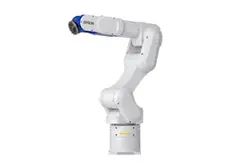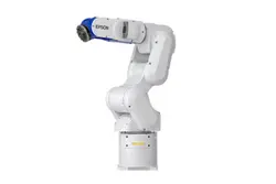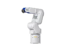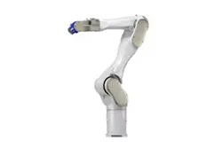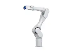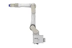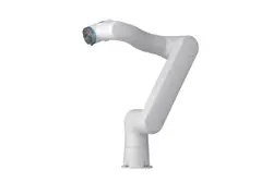

Collaborative Robot
6-Axis Robots AX6
Manual
Original Instructions
©Seiko Epson Corporation 2026
Rev. 2
ENM268R9117M

Collaborative Robot 6-Axis Robots AX6 - Manual
Table of Contents
Terms of Use......................................................................................................................................4
Safety Manual....................................................................................................................................4
Introduction....................................................................................................................................... 5
System Overview...............................................................................................................................6
1. Safety................................................................................................................................................... 7
1.1 Conventions.................................................................................................................................8
1.2 Intended Use................................................................................................................................9
1.3 Installation and Operation Safety.............................................................................................. 10
1.4 Power Failure.............................................................................................................................12
1.5 Movement Without Drive Power...............................................................................................12
1.6 Labels.........................................................................................................................................13
2. Specification......................................................................................................................................14
2.1 Model Number...........................................................................................................................15
2.2 Overview and Part Names......................................................................................................... 15
2.3 Dimensions and Workspace.......................................................................................................16
2.4 Technical Data........................................................................................................................... 18
2.5 Maximum Performance Limits..................................................................................................19
2.5.1 Payload Limitations......................................................................................................... 19
2.5.2 Thermal Limitations.........................................................................................................21
2.6 Stopping Time and Stopping Distance...................................................................................... 21
2.7 Manipulator Lifetime.................................................................................................................23
2.8 Material List.............................................................................................................................. 23
2.9 Emissions...................................................................................................................................23
2.9.1 Noise................................................................................................................................ 23
2.9.2 Clean Room......................................................................................................................23
3. Installation........................................................................................................................................ 24
3.1 Environment.............................................................................................................................. 25
3.2 Unpacking, Packing and Transporting...................................................................................... 25
3.2.1 Packing Pose.................................................................................................................... 27
3.3 Mounting Orientation................................................................................................................ 27
3.4 Installation................................................................................................................................. 28
3.4.1 Mounting Area................................................................................................................. 29
3.4.2 Mounting the Manipulator............................................................................................... 29
3.4.3 Mounting Surface Requirements..................................................................................... 31
3.4.4 Connecting the Cables..................................................................................................... 32
3.5 Status Indicators........................................................................................................................ 33
3.5.1 LED Status Ring.............................................................................................................. 33
3.6 Control Buttons......................................................................................................................... 34
4. End-Effector Interfaces................................................................................................................... 35
4.1 Introduction............................................................................................................................... 36
4.2 Weight and Inertia Settings........................................................................................................36
4.3 Mechanical End-Effector Interface........................................................................................... 36
2

Collaborative Robot 6-Axis Robots AX6 - Manual
4.4 Connector Protectors................................................................................................................. 37
4.5 Air Connectors...........................................................................................................................38
4.6 Electrical Interface to End-Effector (Tool I/O)......................................................................... 39
4.6.1 Introduction......................................................................................................................39
4.6.2 Tool Connector Type and Pin Assignment.......................................................................40
4.6.3 I/O Configuration.............................................................................................................40
4.6.4 I/O Supply........................................................................................................................41
4.6.5 Digital Inputs (Tool I/O).................................................................................................. 41
4.6.6 Digital Outputs (Tool I/O)................................................................................................44
4.6.7 Analog Inputs (Tool I/O)..................................................................................................46
4.6.8 Analog Outputs (Tool I/O)...............................................................................................47
4.7 Ethernet Line............................................................................................................................. 48
5. Maintenance..................................................................................................................................... 49
5.1 Introduction............................................................................................................................... 50
5.2 Cleaning of the Manipulator and Controller..............................................................................50
5.3 Maintenance Inspection.............................................................................................................51
5.4 Repair.........................................................................................................................................52
3

Collaborative Robot 6-Axis Robots AX6 - Manual
Terms of Use
No part of this instruction manual may be reproduced or reprinted in any form without express written
permission.
The information in this document is subject to change without notice.
Please contact us if you find any errors in this document or if you have any questions about the
information in this document.
Safety Manual
The following information is provided in the Safety Manual:
● Manufacturer
● Importer
● Contact Information
● Disposal
For details, refer to the “AX6 / RC-A101 Safety Manual.”
4

Collaborative Robot 6-Axis Robots AX6 - Manual
Introduction
Thank you for purchasing this Epson robot system. This manual provides the information necessary
for correctly using the robot system.
Before using the system, please read this manual and related manuals (see “AX6 / RC-A101 Safety
Manual”) to ensure correct use.
After reading this manual, store it in an easily accessible location for future reference.
Epson conducts rigorous testing and inspection to ensure that the performance of their robot systems
meets their standards. Please note that if the Epson robot system is used outside the operating
conditions described in the manual, the product will not perform up to its basic performance.
This manual describes potential hazards and problems that are foreseen. To use the Epson robot
system safely and correctly, be sure to follow the safety information contained in this manual.
5
Collaborative Robot 6-Axis Robots AX6 - Manual
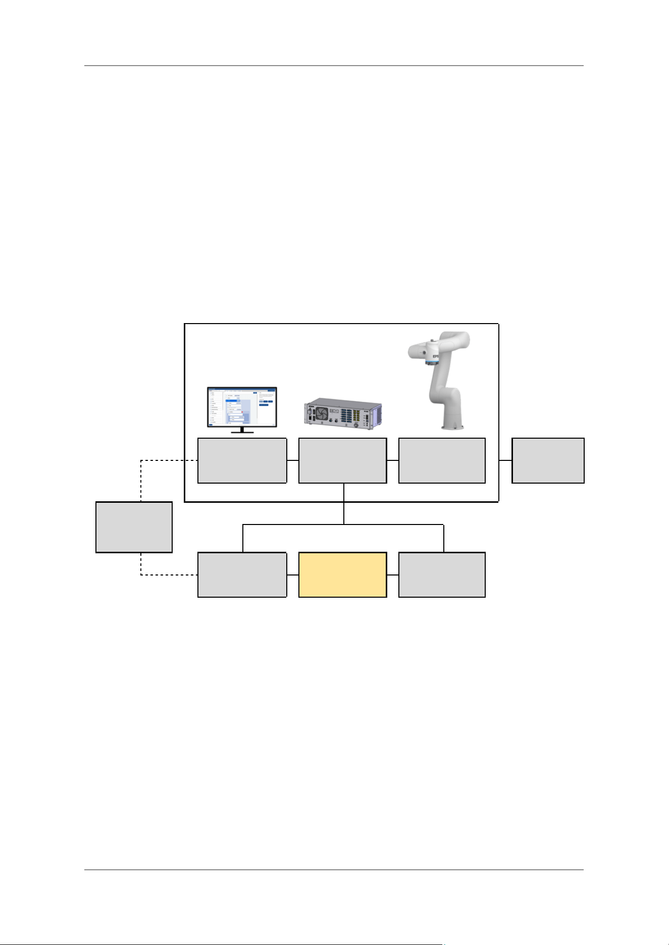
System Overview
AX6 is the name of the six degrees of freedom light-weight robotic manipulator. AX6 is born to work
with humans. As the latest generation of personal, innovative and versatile robots, AX6 is perfectly
suited to take over complex automation tasks, carry out precise laboratory processes or serve
universities as research robots.
The powerful and versatile, web-based AX Portal software opens up unprecedented possibilities.
From intuitive graphical programming to sophisticated Python code – AX Portal offers every
programmer easy access. Thanks to the many interfaces, AX6 can be easily integrated into existing
systems. Peripheral devices such as grippers, cameras or external axes can be seamlessly integrated.
Many industrial buses as well as ROS are supported. External, safe control panels ensure a high level
of operating convenience for the operator.
For the operation of the AX6 manipulator, the controller RC-A101 is required (delivered with AX6).
Content of the Package
Epson AX Portal
Software
Controller Box
RC-A101
Manipulator
AX6-A901S
End Tool
(Gripper)
Web Browser
Computer or
Tablet
Safety Device
Peripheral
Devices
Overview
6

Collaborative Robot 6-Axis Robots AX6 - Manual
1. Safety
7
Collaborative Robot 6-Axis Robots AX6 - Manual
1.1 Conventions
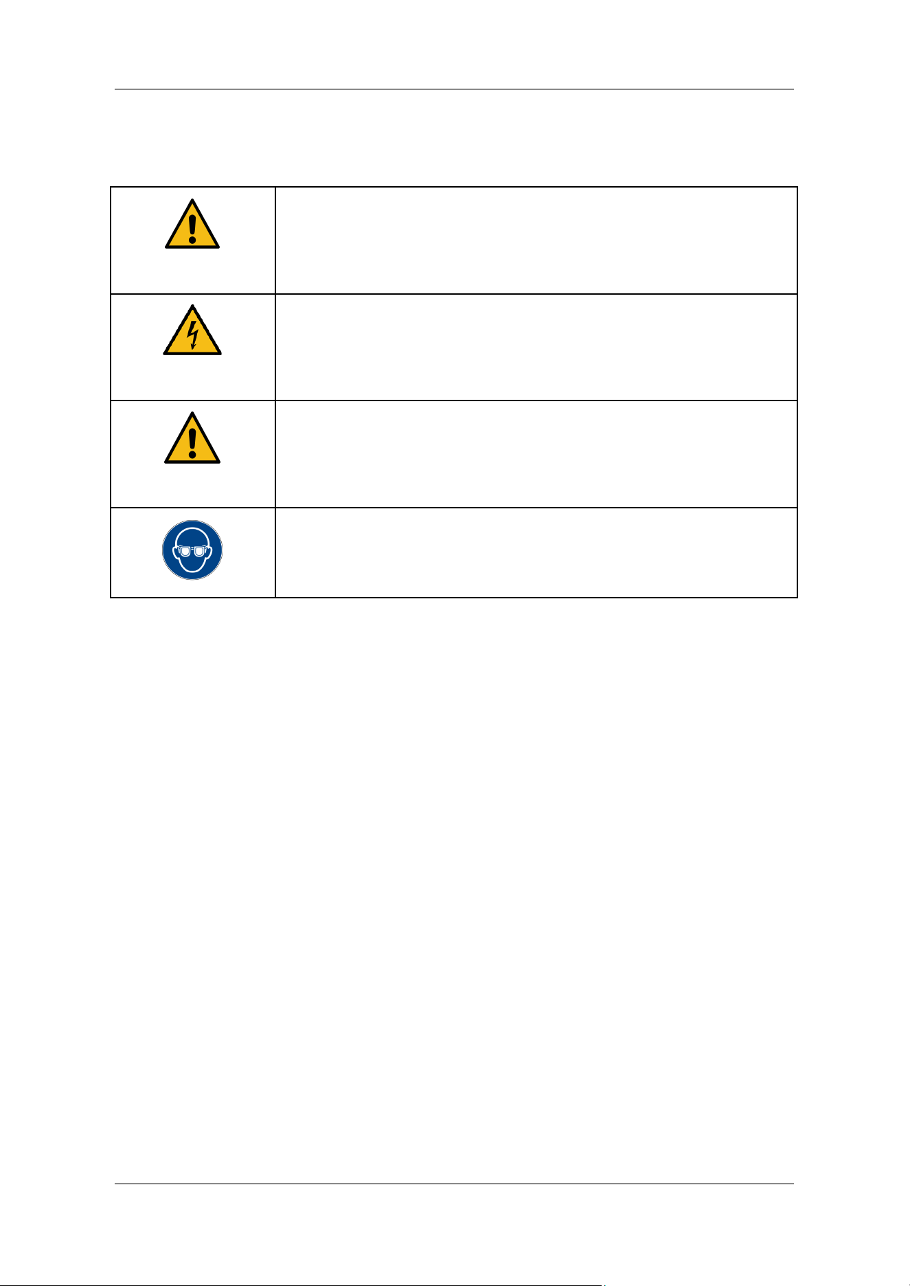
The table below explains the symbols used in this document and on the product itself.
WARNING
This symbol indicates that a danger of possible serious injury or death
exists if the associated instructions are not followed.
WARNING
This symbol indicates that a danger of possible harm to people or death
caused by electric shock exists if the associated instructions are not
followed properly.
CAUTION
This symbol indicates that a danger of possible harm to people or physical
damage to equipment and facilities exists if the associated instructions are
not followed properly.
This symbol indicates that safety goggles must be worn.
8
Collaborative Robot 6-Axis Robots AX6 - Manual
1.2 Intended Use
AX6 is normally integrated into a production line and it usually works with grippers or other end
effectors. Before AX6 is used for the first time, a risk assessment must be carried out for the final
system into which AX6 is to be integrated. This risk assessment must conform to the country-specific
safety standards and directives. In the case of collaborative applications, special attention must be paid
for avoiding hazards to humans in the risk assessment. AX6 may be used across different industries
for stationary or mobile applications. Its main purpose is handling or assembling parts, executing
automated processes with end effectors, tools or fixtures and direct interaction with people when the
safety functions for collaborative operation are enabled.
WARNING
Any use that does not fall within the intended use is considered misuse and
is not permitted.
Some examples of misuse (the list is not exhaustive):
● Any application that causes harm to humans or animals.
● Any application that could endanger human or animal life or cause
injury in the event of a malfunction.
● Handling or use of hazardous objects or substances in
collaborative applications.
● Exceeding the specified operating limits or operating the robot not
within the allowed environmental conditions.
● Lifting any humans or animals.
● Use in explosive environments.
9
Collaborative Robot 6-Axis Robots AX6 - Manual
1.3 Installation and Operation Safety
The design and installation of this robot system must be carried out by personnel who have been
trained in robotic systems by us or our suppliers. Users must undergo system-specific training and be
informed about all safety aspects.
This robot comes with integrated safety functions which allow collaborative applications. To declare
an application as collaborative, it must be proven in the mandatory risk analysis that the robot is not
hazardous. Otherwise the working area of the robot must be safeguarded. For detailed information
about robot safety, see “AX6 / RC-A101 Safety Manual”.
10
WARNING
Pay attention to the following safety instructions:
● Please read this manual, the “Robot Controller RC-A101 Manual”
and the “AX6 / RC-A101 Safety Manual” before using this robot
system. Operating the robot system without understanding the
safety precautions is extremely hazardous and may result in
serious bodily injury and/or severe equipment damage to the robot
system.
● The robot system must be used in accordance with the
environmental conditions described in the relevant manual. Using
the product in an environment that exceeds these conditions can
shorten its service life and cause serious safety problems.
● Collaborative applications: Although the collision detection
reduces the hazard of collisions with the human body to a
minimum, the risk of collisions with head and neck must be
prevented.
● Non-collaborative applications: Do not enter the operating area of
the manipulator while the robot is powered-up and make sure that
no one is inside this area before powering up. Being within the
operating area of a powered-up manipulator is extremely
hazardous and may cause serious safety problems as the
manipulator may move even if it seems to be stopped.
● Immediately press the emergency stop button whenever the
manipulator moves abnormally during operation. Continuing the
operation while the manipulator moves abnormally is extremely
hazardous and may result in serious bodily injury and/or severe
equipment damage to the robot system.
● Only use original parts purchased from us or our partners for the
repair and wiring of this robot system. The use of third-party
components can lead to electric shock, serious injury, malfunction
and/or damage to the robot system.
Collaborative Robot 6-Axis Robots AX6 - Manual
WARNING
Pay attention to the following safety instructions regarding electricity:
● Before performing any replacement procedure, turn the controller
and related equipment off, and then disconnect the power plug
from the power source. Performing any replacement procedure
with the power on is extremely hazardous and may result in
electric shock and/or malfunction of the robot system.
CAUTION
In addition to the safety instructions, note the following:
● Whenever possible, only one person should operate the robot
system. If it is necessary to operate with more than one person,
ensure that all personnel communicate with each other and take all
necessary safety precautions.
● If the joints are operated repeatedly with the operating angle less
than 5 degrees, they may get damaged early because the bearings
are likely to cause oil film shortage in such a situation. To prevent
early breakdown, move each joint larger than 30 degrees for about
once an hour.
● When the manipulator moves, continuous vibrations (resonance)
may occur depending on the combination of manipulator
orientation and end effector load. These vibrations are caused by
the natural frequency of the manipulator and can be controlled by
the following measures:
○ Changing the manipulator speed
○ Changing the position
○ Changing the end effector mass
11

Collaborative Robot 6-Axis Robots AX6 - Manual
1.4 Power Failure
Do not turn off the controller while the manipulator is operating. The lifetime of the gears may be
reduced and there may be wear on the brakes.
If the control unit was switched off due to a power failure while the manipulator was in operation, you
should check the following points once the power supply has been restored:
● If a reduction gear is damaged.
● Proper functioning of the brakes in all 6 joints
1.5 Movement Without Drive Power
There are two ways to move the manipulator away if not powered. Please check always if it is feasible
to move the robot in the hand-guided mode before you try one of the following methods.
1) Pull or Push on the Robot Links
If the power supply is disconnected or the emergency stop is pressed, the brakes in each joint hold the
robot in its position. In these cases, the joints can be moved by hand by pulling or pushing on the
robot links with sufficient force. The table below shows the estimated brake torque, but please note
that the torque can deviate from the specified values by up to 50 %.
Joint
AX6
1
200 Nm
2
3
4
30 Nm
5
6
Note that this can shift the TCP slightly. If you realise a TCP shift, perform calibration by referring to
the “Robot Manipulator AX6 - Service Manual”.
Manuals for maintenance and service are not included with the product. Maintenance should be
performed by people who have received maintenance training provided by Epson and the suppliers.
For more information, please contact the supplier.
This may be necessary in the case of an emergency, e.g. if a person is trapped. Only move the joints
manually if no other option is available.
2) Unscrew the Manipulator
12

Collaborative Robot 6-Axis Robots AX6 - Manual
In some cases, it might be easier to unscrew the manipulator instead of moving the joints by hand. It is
therefore also important that the screws that fix the manipulator are always accessible (i.e. not
covered).
1.6 Labels
Be sure to comply with information and warnings on the labels to operate and maintain the
manipulator safely. Do not tear, damage, or remove the labels.
For details consult the “AX6 / RC-A101 Safety Manual”.
13

Collaborative Robot 6-Axis Robots AX6 - Manual
2. Specification
14
Collaborative Robot 6-Axis Robots AX6 - Manual
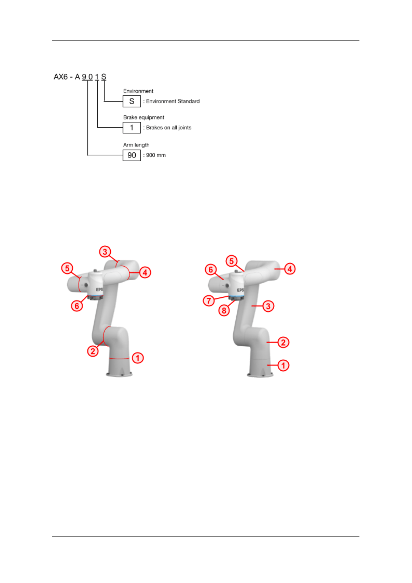
2.1 Model Number
2.2 Overview and Part Names
AX6 is a robotic manipulator with six degrees of freedom. The manipulator structure is made of rigid
and lightweight carbon-fibre-reinforced polymers and aluminium. The image below shows an
overview of the robot's structure.
1. Joint 1
3. Joint 3
5. Joint 5
2. Joint 2
4. Joint 4
6. Joint 6
1. Base
2. Link 2-3
5. Link 4-5
7. LED Ring
2. Link 1-2
4. Link 3-4
6. Link 5-6
8. End Tool Interface
The robot can be fixed rigidly to a solid surface with four screws, while positioning pins or precise
positioning surfaces on the base ensure exact alignment.
Each joint is driven by a brushless motor with safe absolute encoders. Strain wave gearboxes ensure
maximum transmission accuracy. State-of-the-art drive technology ensures smooth and safe operation.
15
Collaborative Robot 6-Axis Robots AX6 - Manual
2.3 Dimensions and Workspace
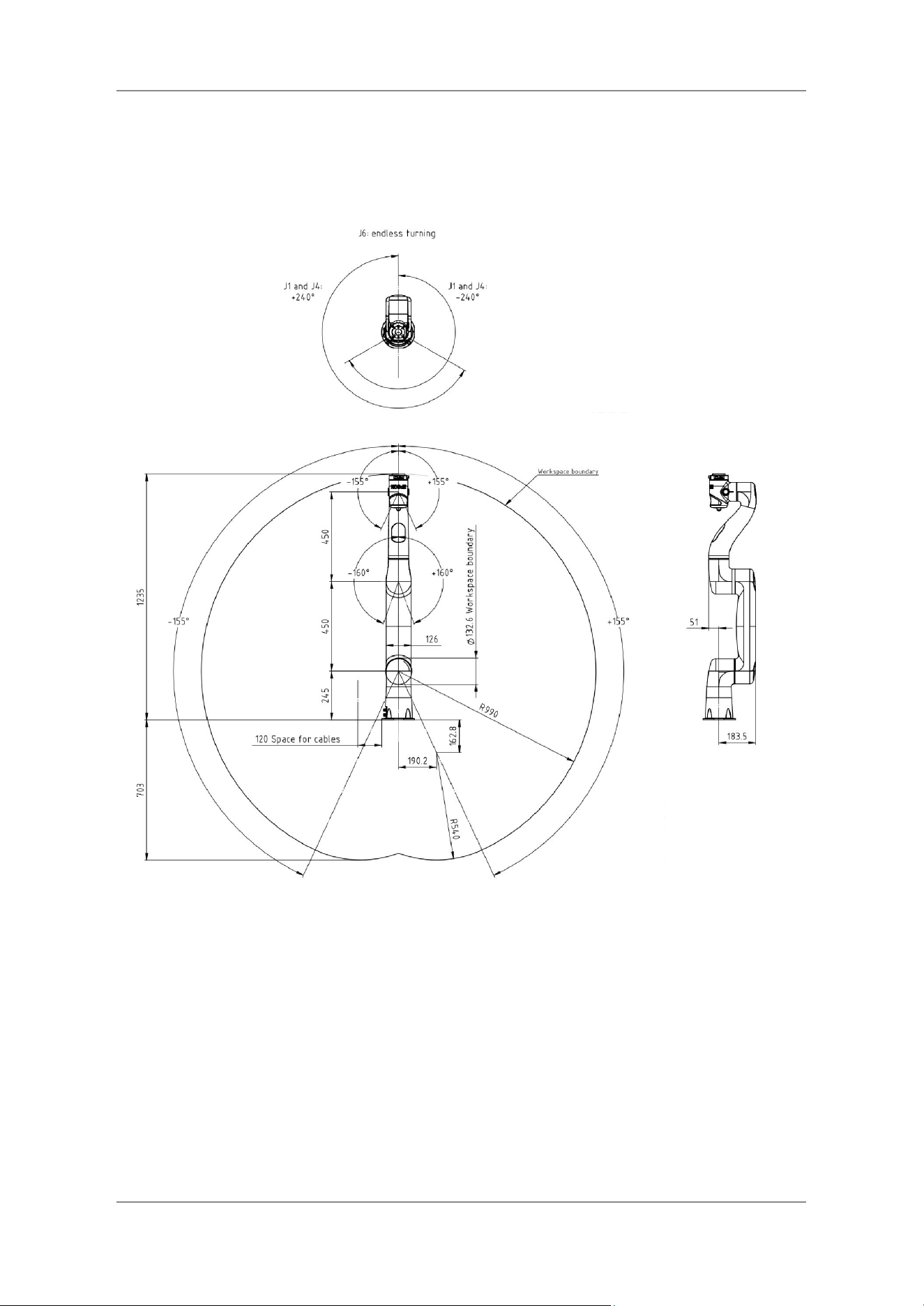
The drawing below shows the working space of AX6. Note that not every position within the
workspace will be accessible with every possible orientation of the end-effector.
Working range of AX6.
16
Collaborative Robot 6-Axis Robots AX6 - Manual
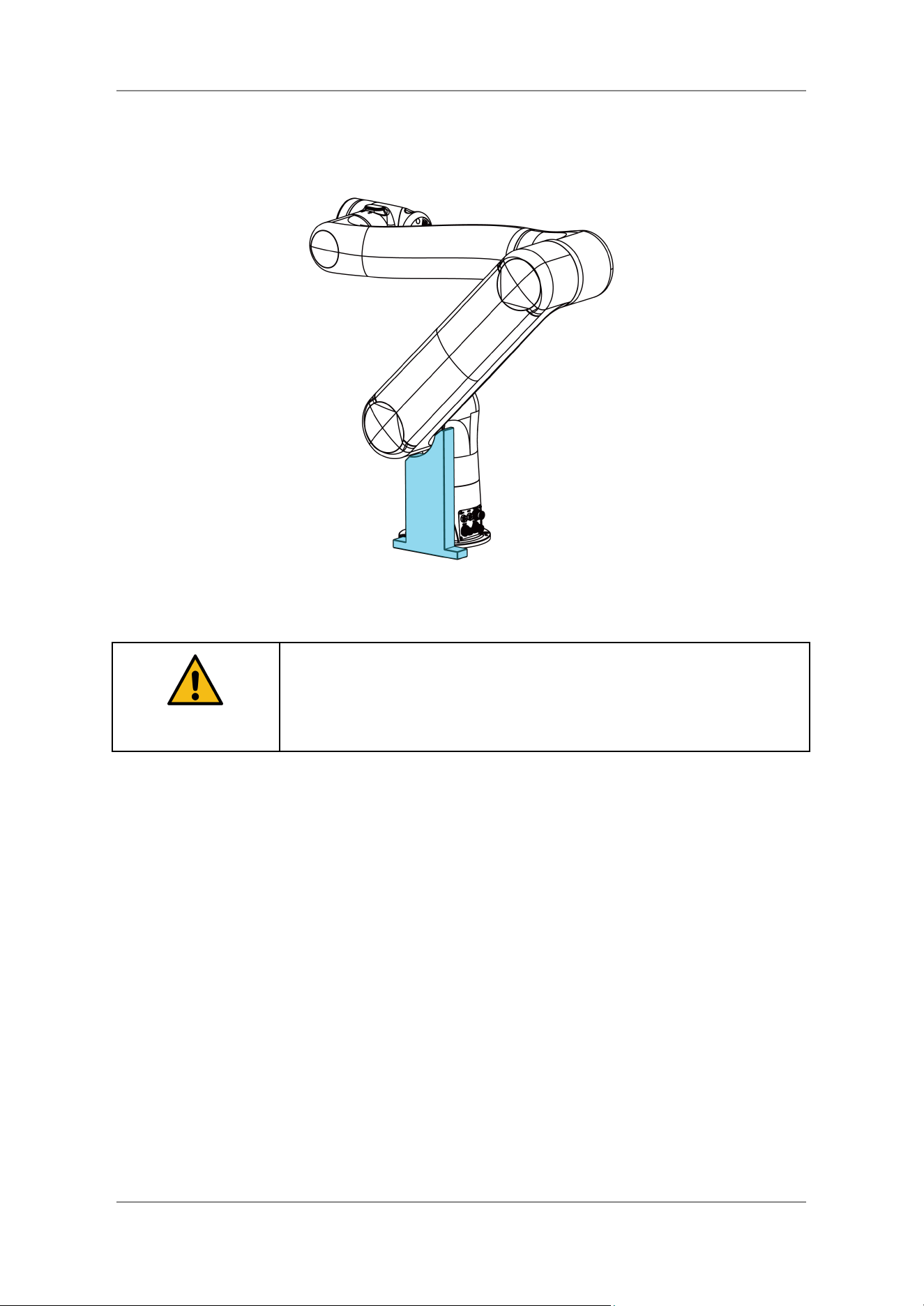
If mechanical limitations are required, the customer must prepare and install appropriate mechanical
stoppers. The shaded areas shown in the illustration represent examples of mechanical stoppers.
Example of the mechanical stopper
WARNING
Ensure, by means of suitable barriers or safety devices, that fingers or other
body parts cannot become trapped when using a mechanical stop.
Furthermore, position the mechanical stop so that it cannot damage the
robot.
When preparing the mechanical stopper, use the following specifications as a guideline:
● Material: Equivalent to S45C
● Mechanical stopper thickness: 30 mm or more
● Mounting bolt: M10 or larger
● Mounting bolt seat thickness: 15 mm or more
17
Collaborative Robot 6-Axis Robots AX6 - Manual
2.4 Technical Data
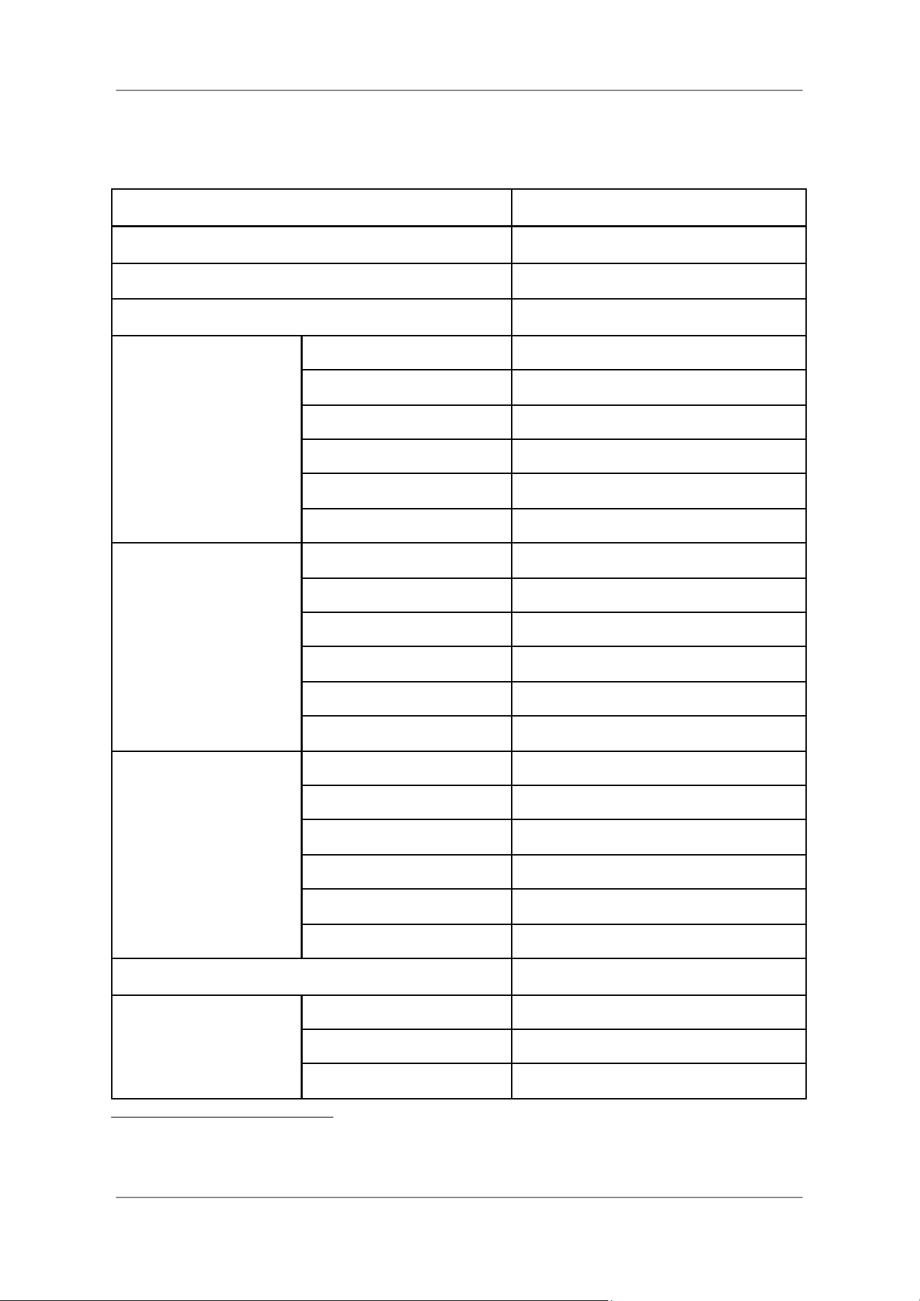
The table below shows technical data of the manipulator.
Model
AX6
Reach (J1 center to J5 center)
900 mm
Manipulator Weight (without cables)
18 kg
Maximum Payload
6 kg
Maximum Operation
Speed
Joint 1
180 °/s
Joint 2
180 °/s
Joint 3
180 °/s
Joint 4
240 °/s
Joint 5
240 °/s
Joint 6
240 °/s
Maximum Operation
Acceleration
Joint 1
500 °/s
2
Joint 2
500 °/s
2
Joint 3
500 °/s
2
Joint 4
1000 °/s
2
Joint 5
1000 °/s
2
Joint 6
1000 °/s
2
Maximum Motion
Range
Joint 1
±240°
Joint 2
±155°
Joint 3
±160°
Joint 4
±240°
Joint 5
±155°
Joint 6
No limit
1
Maximum Cartesian Speed at TCP
2000 mm/s
Allowable Moment
Joint 4
24 Nm
Joint 5
24 Nm
Joint 6
24 Nm
1
There is a multiturn counter limit at ±50 full rotations of joint 6. Motions beyond this limit are not
possible. When using an Ethernet cable and/or air tubes connected to an end-effector, they limit the
movement of joint 6.
18
Collaborative Robot 6-Axis Robots AX6 - Manual
Allowable Moment of
Inertia (GD
2
/4)
Joint 4
0.6 Nm
Joint 5
0.6 Nm
Joint 6
0.6 Nm
Repeatability
±0.03 mm
M/C Cable
Power cable
0.5 m, 1.5 m, 3 m, 5 m
Signal cable
0.5 m, 1.5 m, 3 m, 5 m
2.5 Maximum Performance Limits
2.5.1 Payload Limitations
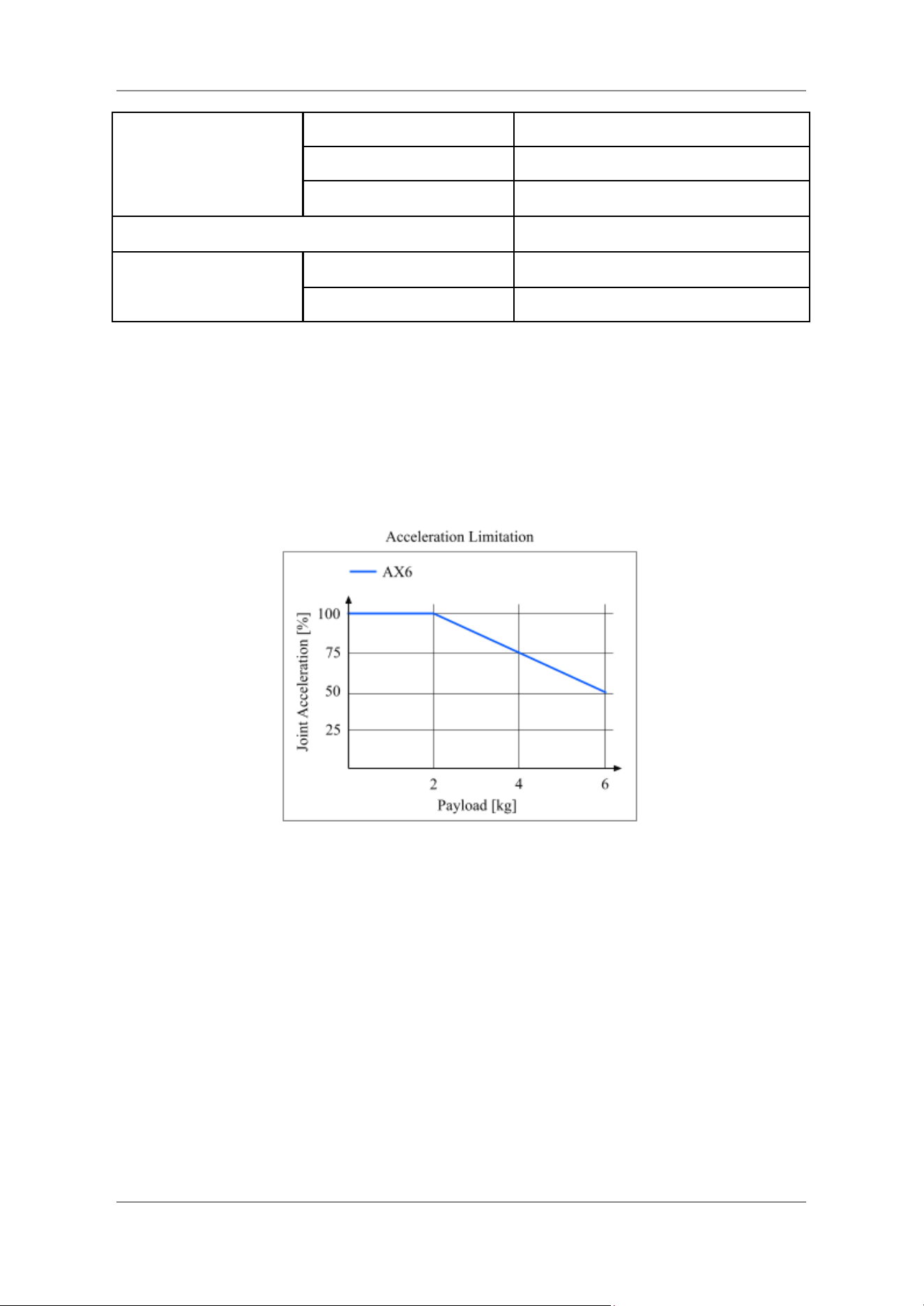
The maximum possible joint acceleration depends on the payload (tool mass and object mass), as
visualised in the graph below. To set the correct payload, please refer to the “AX Portal User’s
Guide”.
19
Collaborative Robot 6-Axis Robots AX6 - Manual
Distances to Payload.
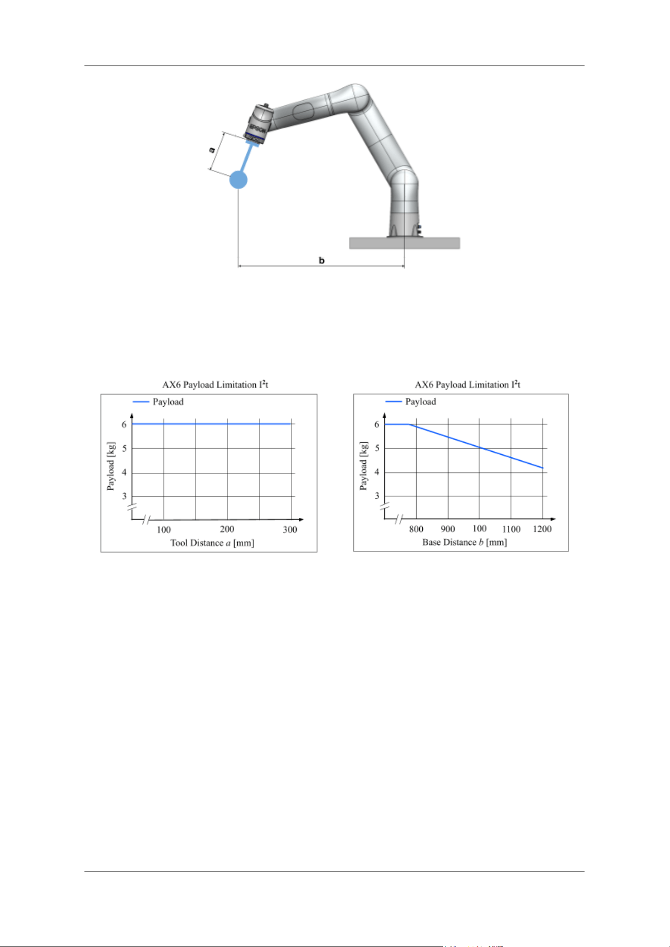
If the center of gravity of the payload is far away from the end tool interface (Tool Distance a in the
image) or the robot base (Base Distance b), further limitations may apply as shown in the graphs
below.
20
Collaborative Robot 6-Axis Robots AX6 - Manual
2.5.2 Thermal Limitations
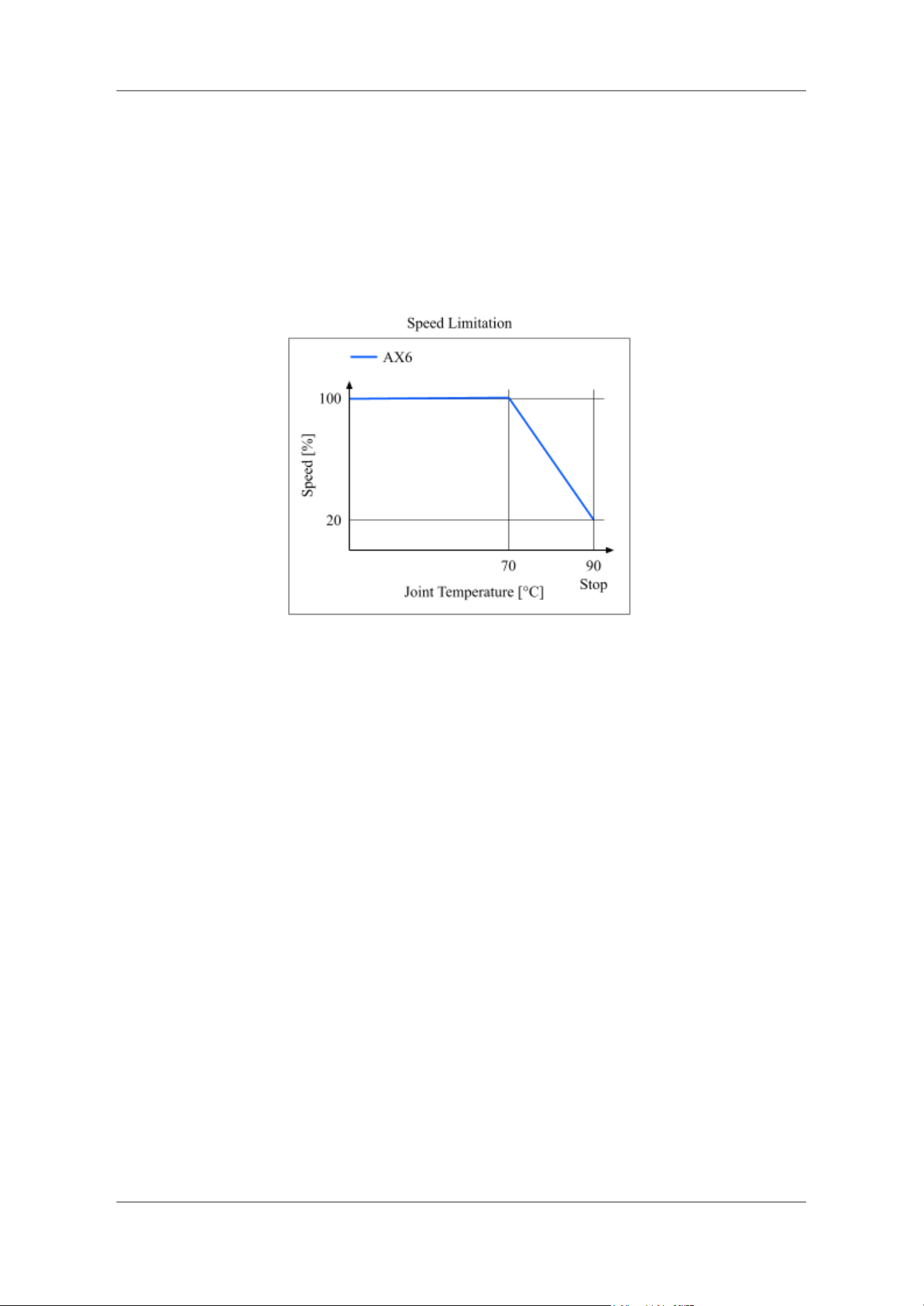
Please note that thermal limitations apply. While a demanding motion can be easily done for a certain
time, it might overheat the drives when done repeatedly without interruption. A thermal protection
protects the robot from damage by limiting the maximum speed of the robot when the joint
temperature reaches 70 °C. If the temperature rises to 90 °C, the robot stops, see graph below.
It is
possible to deactivate the speed limitation from 70 °C. Please note that in this case the critical 90 °C,
where the robot stops in any case, can be reached more quickly. See “AX Portal User’s Guide”.
It is recommended to monitor the joint temperature in the AX Portal when the robot is used in
applications with high speed or payload. A reduction in the temperature can be achieved by reducing
the application speed, the payload or by optimising the paths.
In addition to the joint temperature sensor,a protection function is provided to prevent overheating
caused by high continuous currents. This may happen if the maximum payload of the robot is
exceeded or a continuous external force is applied.
2.6 Stopping Time and Stopping Distance
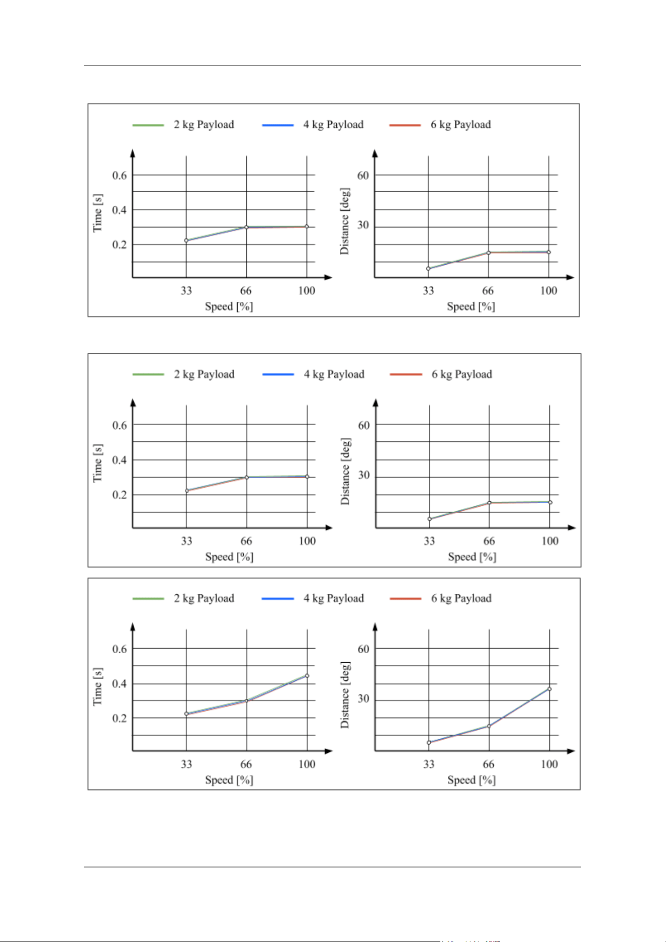
The graphs below show the stopping time and the stopping distance as a function of the joint speed.
The graphs apply to stops of the stop categories 1 and 2 according to IEC 60204-1 and were recorded
for joint 1, 2 and 3.
The joints were tested under the following conditions:
● Joint 1: moving horizontally, TCP 900 mm away from joint 1
● Joint 2: moving downwards, TCP 900 mm away from joint 2
● Joint 3: moving downwards, TCP 450 mm away from joint 3
Note that joint 1 and joint 2 do not reach 100 % speed (180 °/s) when the TCP is 900 mm away from
the joints due to the cartesian speed limit. This is why bigger values were measured for joint 3. If the
distance between the joint and the TCP is set so that the limit does not apply, joints 1 and 2 behave in
the same way as joint 3.
21
Collaborative Robot 6-Axis Robots AX6 - Manual
AX6: Joint 1 (table mounting, ceiling mounting)
AX6: Joint 2 (table mounting, ceiling mounting)
AX6: Joint 3 (table mounting, ceiling mounting)
22

Collaborative Robot 6-Axis Robots AX6 - Manual
2.7 Manipulator Lifetime
Usually, the lifetime of the manipulator is limited by the lifetime of the gears. The joint with the
highest load is usually joint 2 (or joint 1 for wall mounting) but it depends on the application. The
lifetime of the gearbox depends heavily on the torques acting in the joints, i.e. on the load, the
temperature, the speed profile and the programmed positions. To keep the service life of the robot as
long as possible, it is recommended to review the application for unnecessarily high acceleration and
deceleration values and keep the joint temperatures low. Furthermore, regular maintenance checks
help to ensure that the manipulator has the longest possible service life, see Maintenance Inspection.
For typical applications, it is recommended that you consider replacing parts (e.g. joints) after
approximately 20,000 hours. At this point, heavily loaded manipulator joints may lead to a loss of
accuracy or malfunctions due to signs of wear caused by the manipulator’s long-term operation. As
mentioned above, the extent to which each joint is loaded depends heavily on the application, which is
why the 20,000 hours mentioned is a reference value that may be reached sooner under heavy loads,
but is very often exceeded.
2.8 Material List
The list below shows the mainly used materials used for the manipulator's outer shell:
● Painted aluminium: Base, link 1–2, link 3–4, link 5–6
● Aluminium: Base, link 5–6 (usually concealed by the air and Ethernet connector covers)
● Painted carbon fibre reinforced polymers: Link 2–3, link 4–5
● Painted polyamide (PA): Covers on link 2–3 and link 4–5
● Anodised aluminium: End tool interface, sheet on the bottom of the base, air fittings
● Stainless steel: Sheet where the connectors are attached, washers in the base
● Thermoplastic elastomers (TPE): Rubber covers and buttons on link 5–6
● NBR/PVC polyblend: Button on link 5–6
● Polycarbonate (PC): LED ring
● Nickel-plated metal: Connectors
● Galvanised and stainless screws
2.9 Emissions
2.9.1 Noise
Typically, the noise emission of the manipulator is 75 dB, measured at a distance of 1 m away from
the manipulator.
2.9.2 Clean Room
The manipulator conforms to cleanroom specification ISO 14644-1 Class 5.
23

Collaborative Robot 6-Axis Robots AX6 - Manual
3. Installation
24

Collaborative Robot 6-Axis Robots AX6 - Manual
3.1 Environment
A suitable environment is necessary for the robot system to function properly and safely. Be sure to
install the robot system in an environment that meets the following conditions:
Environment
Condition
Ambient temperature
2
Transport/Storage: –20 to 60 °C
Operation: 5 to 40 °C
Ambient relative humidity
Transport/Storage: 10 to 90 % (no condensation)
Operation: 10 to 80 % (no condensation)
Fast transient burst noise
1 kV or less
Electrostatic discharge
4 kV or less
Altitude
Max. 2000 m
Ingress protection code
IP 54
3
Please make sure:
● Install indoors.
● Keep away from dust, oily smoke, salinity, metal powder or other contaminants.
● Keep away from flammable or corrosive solvents and gases.
● Keep away from water (see ingress protection code in the table above).
● Keep away from shocks or vibrations.
● Keep away from sources of electric noise above specifications.
● Keep away from explosive areas.
● Keep away from a large quantity of radiation.
Rapid changes in temperature and humidity can lead to condensation inside the manipulator which
can lead to damage or degradation. Avoid bringing a cold robot into a warm area to prevent
condensation and never power up a robot when it is wet.
3.2 Unpacking, Packing and Transporting
Unpacking, packing and transporting must be carried out by personnel who have attended our training
sessions on robot systems or those of our suppliers. All national and local codes must be adhered to. It
is recommended that the robot always be transported in its original packaging.
3
The IP 54 dustproof and water‑resistant rating is based on a design evaluation of the manipulator body, power
cable, and signal cable, conducted with reference to the applicable standards. This information is provided for
reference only and does not guarantee the performance of the robot at the time of shipment or under actual
installation and operating conditions.
2
Please note that the collision detection for power and force limiting may detect false positive collisions when
the robot is used close to the minimum specified temperature. In such a case, it is recommended to warm up the
robot prior to collaborative operation.
25
Collaborative Robot 6-Axis Robots AX6 - Manual
WARNING
When installing, comply with the legal regulations regarding the carrying
of heavy loads. Carrying loads that are too heavy can cause permanent
injury.
CAUTION
Before installing, transporting or relocating the manipulator, please note
the following:
● The manipulator must never be set up, even temporarily, without
being screwed onto a solid surface. It could fall over, which could
result in damage or injury. If it cannot be screwed down, lay it in a
stable position on a solid table.
● When carrying the manipulator by hand, exercise extreme caution.
First, check that your path is free of trip hazards or similar
obstacles. Before carrying the robot, place it in a suitable position.
Carry it in a way that is comfortable for you and prevents it from
slipping out of your hands.
● Be careful not to squeeze your fingers when placing the robot.
● If you are travelling long distances, transport the manipulator using
a suitable handcart. Ensure that the manipulator is stable on the
cart.
● If the manipulator has been stored at temperatures below 5 °C, it
must be left to stand after installation until it has adjusted to the
ambient temperature.
26
Collaborative Robot 6-Axis Robots AX6 - Manual
3.2.1 Packing Pose
To pack the robot in the original packing, the robot should be placed in the position shown in the table
below. These values are also used as the default home position of the robot.
Joint
Angle
J1
0°
J2
–37°
J3
132°
J4
0°
J5
85°
J6
0°
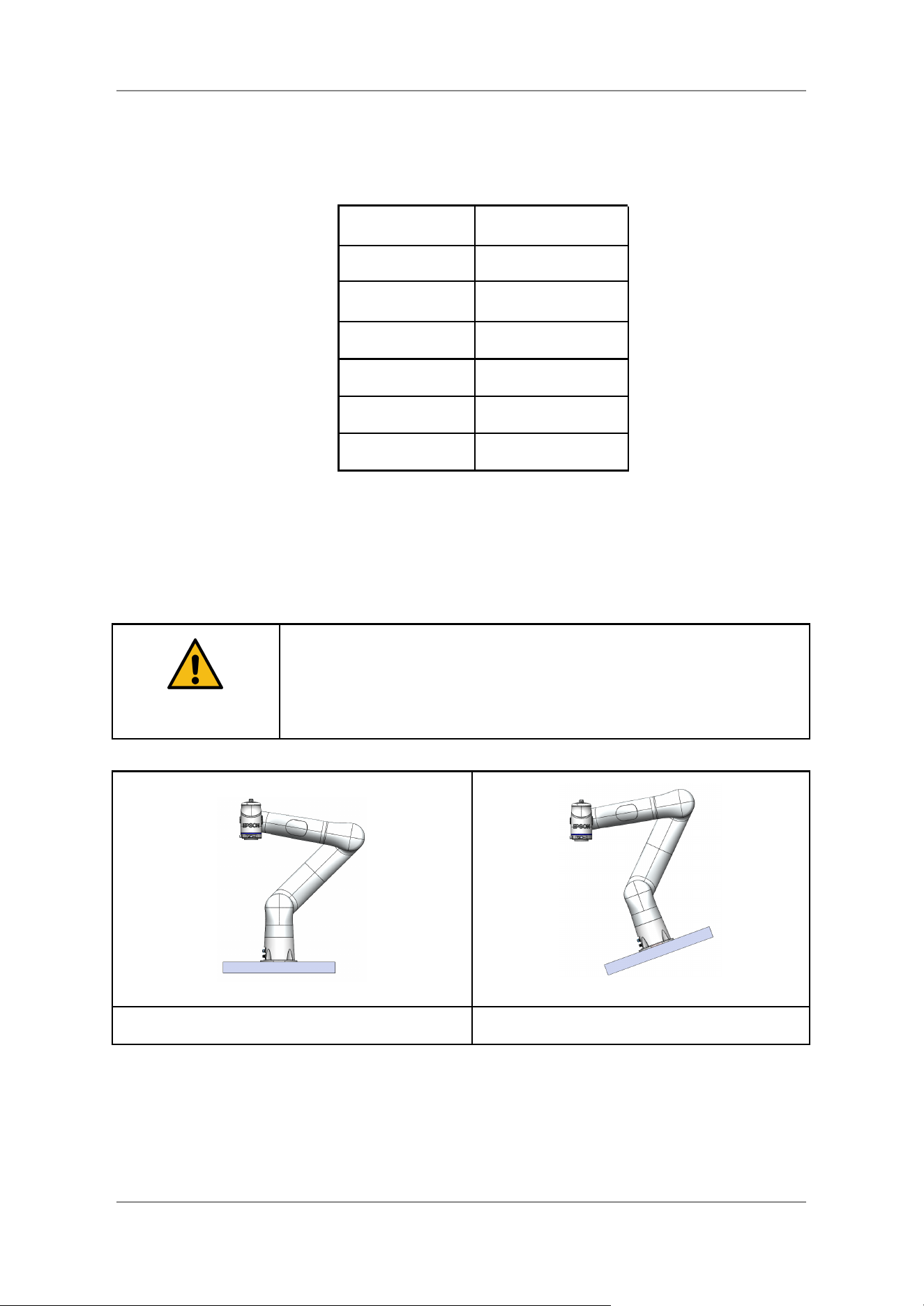
3.3 Mounting Orientation
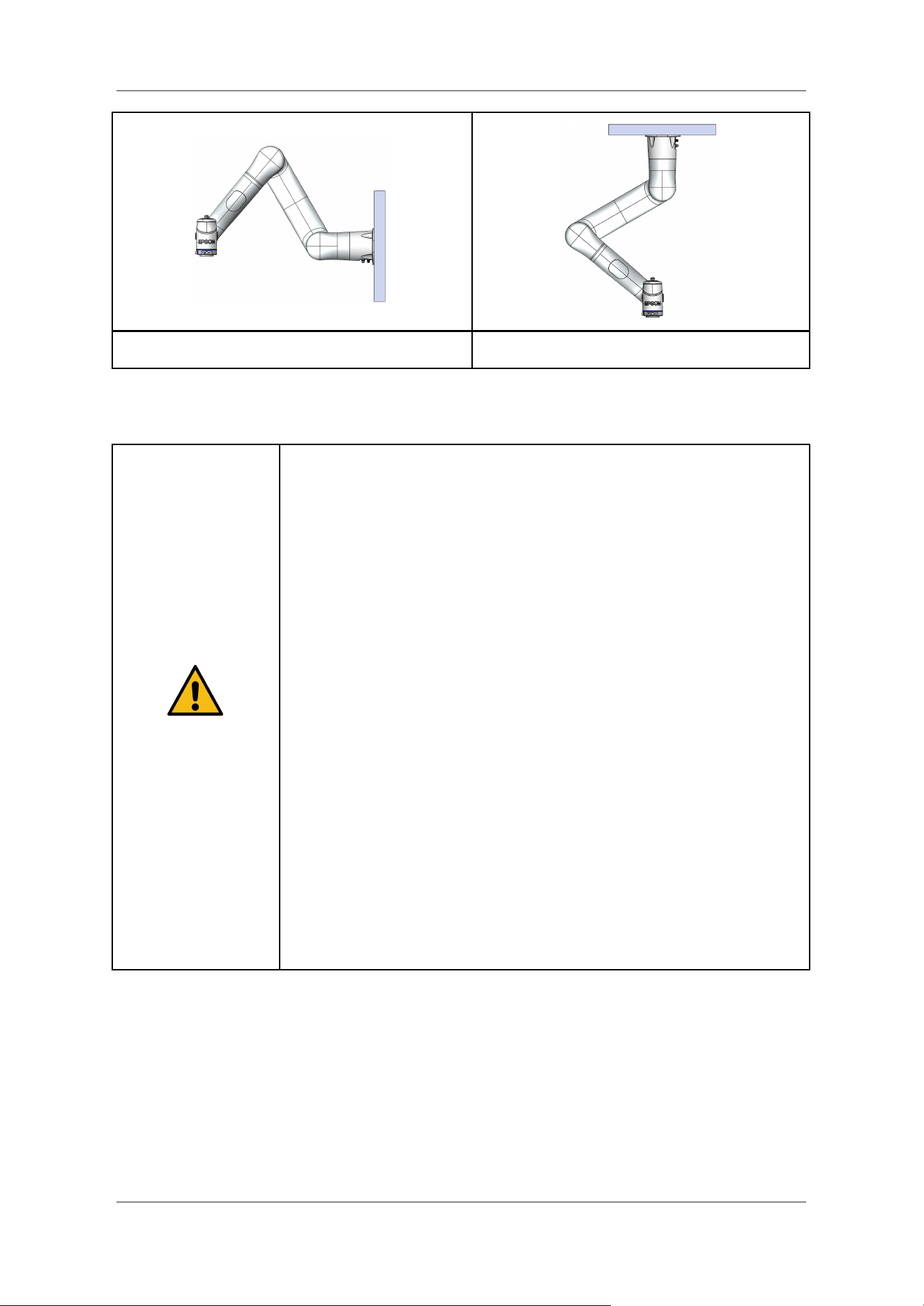
The manipulator can be mounted horizontally (typically on a table, but also on racks or on the floor),
tilted, on a wall or on a ceiling. Every time the mounting orientation is changed, the manipulator
needs to be configured in the AX Portal Safety User Interface, see “AX Portal User’s Guide”.
WARNING
Note that the manipulator is configured for horizontal mounting as
standard. Any other mounting and a change of mounting orientation
requires reconfiguration in AX Portal. Incorrect configuration leads to
unreliable behaviour and unexpected movements in hand-guided mode.
This is extremely hazardous and can lead to material damage and injury.
Horizontal mounting.
Tilted mounting.
27
Collaborative Robot 6-Axis Robots AX6 - Manual
Wall mounting.
Ceiling mounting.
3.4 Installation
WARNING
Always follow the instructions when working with this robot system:
● Never operate the robot without an installed emergency stop
button. Make sure that an emergency stop button is always
accessible. Ignoring this may lead to dangerous situations. For the
wiring of the emergency stop button, please check the “Robot
Controller RC-A101 Manual”.
● Non-collaborative applications: Install the manipulator in a
location with sufficient space so that it, including the gripper and
payload, can never collide with the safety guarding. Installing the
manipulator in a location with insufficient space is extremely
dangerous and can lead to serious personal injury and/or serious
material damage to the robot system.
● Before turning on the power or operating the manipulator, anchor
it. Doing so with an unanchored manipulator is extremely
hazardous and may result in serious bodily injury and/or severe
damage to the robot system, as it may fall down.
● Before installation and operation of the manipulator, ensure that it
is free from external defects. The manipulator may not operate
properly if any of its parts are missing or defective which may
result in serious bodily injury and/or severe damage to the robot
system.
28
Collaborative Robot 6-Axis Robots AX6 - Manual
3.4.1 Mounting Area
Also, besides the area required for installation of the Manipulator, Controller, peripheral equipment,
and other devices, the following space should be provided at a minimum.
● Space for teaching
● Space for maintenance and inspections (for installing jigs and working safely within the
safety barriers)
● Space for cables
3.4.2 Mounting the Manipulator
The robot is screwed on with four M8 screws. Please note the following:
● Use M8 screws that comply with strength class 8.8 of the ISO 898-1 standard.
● Use a fastening torque of 18 Nm.
● The use of a threadlocker is recommended.
● Please ensure that the threads in the mounting plate can withstand the forces.
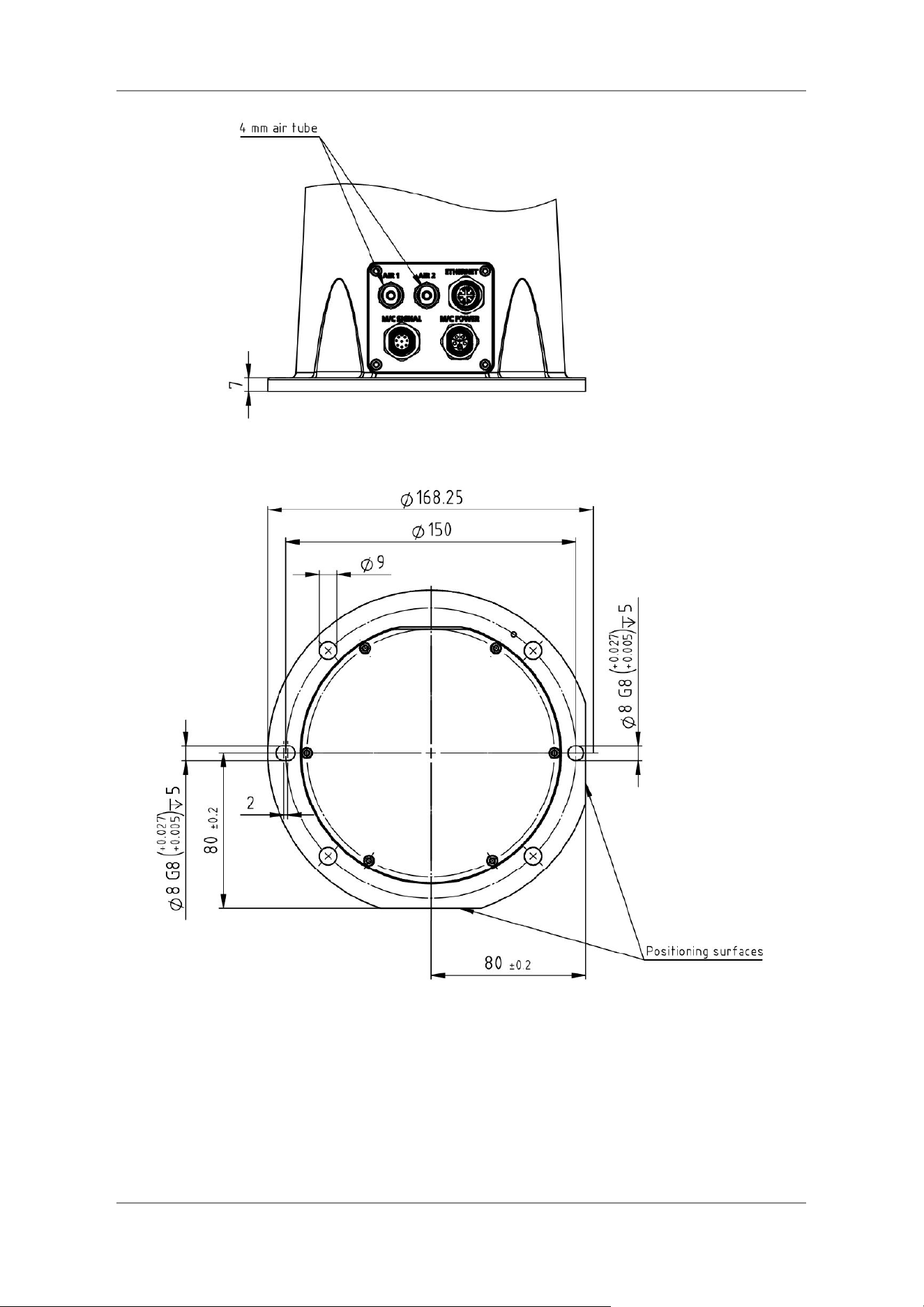
Optionally, the manipulator can be precisely positioned with two dowel pins or using the two
positioning surfaces to facilitate robot replacement. For the geometry, see the drawing below.
WARNING
Make sure that the screws which fix the manipulator are always accessible
(i.e. not covered). You may have to remove the manipulator in case of an
emergency (e.g. when somebody is trapped by the manipulator).
29
Collaborative Robot 6-Axis Robots AX6 - Manual
Base of AX6.
30

Collaborative Robot 6-Axis Robots AX6 - Manual
3.4.3 Mounting Surface Requirements
The mounting surface must support the weight of the manipulator and withstand the dynamic
movements of the manipulator. If mounted on a table. it must be ensured that the table cannot move
on the floor during robot operation. The mounting surface of the manipulator should have a maximum
evenness of 0.2 mm.
The maximum reaction force of the robot is:
AX6
Max. horizontal rotating torque [Nm]
500
Max. horizontal rotating force [N]
500
Max. vertical rotating torque [Nm]
500
Max. vertical rotating force [N]
1000
31
Collaborative Robot 6-Axis Robots AX6 - Manual
3.4.4 Connecting the Cables
WARNING
Always follow the instructions when connecting or disconnecting cables:
● Only authorized or certified personnel should perform wiring.
Wiring carried out by unauthorized or uncertified personnel may
result in injury and/or malfunction of the robot system.
● Always turn the controller off before connecting or disconnecting
cables. Doing so while the controller is switched on may result in
electric shock and/or damage to the robot system.
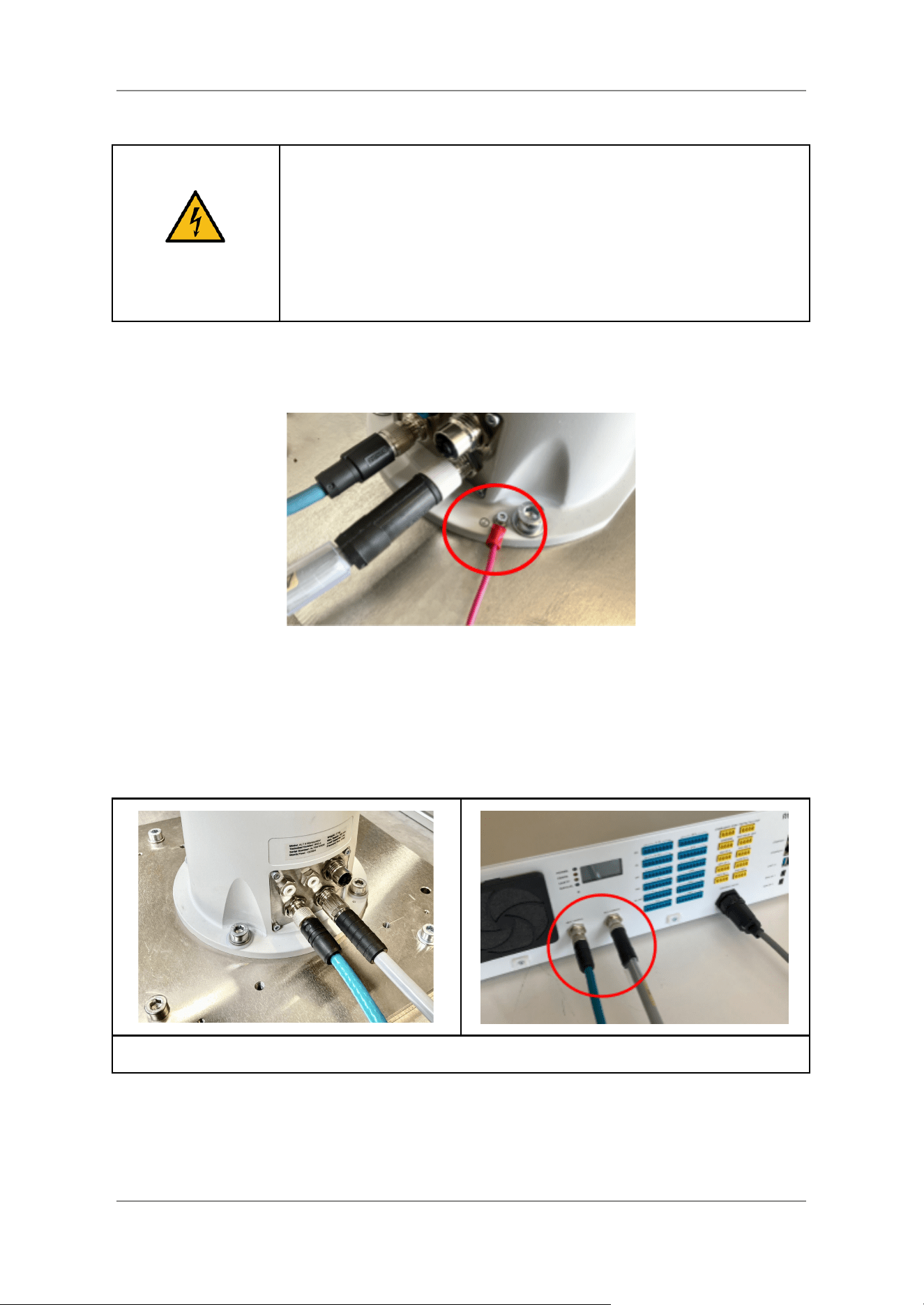
It is highly recommended to connect the manipulator base to a nearby earth outlet for fixed
installations or to the main chassis if used on a DC powered mobile system as shown in the picture
below. Use a suitable (class 8.8 or A2) M3x6 screw with a torque of 0.7 Nm.
Earth connection of manipulator.
Connect the manipulator and the controller with the following cables:
● Power cable (gray)
● Signal cable (green)
Tighten the cables hand-tight.
Connecting the manipulator and the controller.
32
Collaborative Robot 6-Axis Robots AX6 - Manual
3.5 Status Indicators
3.5.1 LED Status Ring
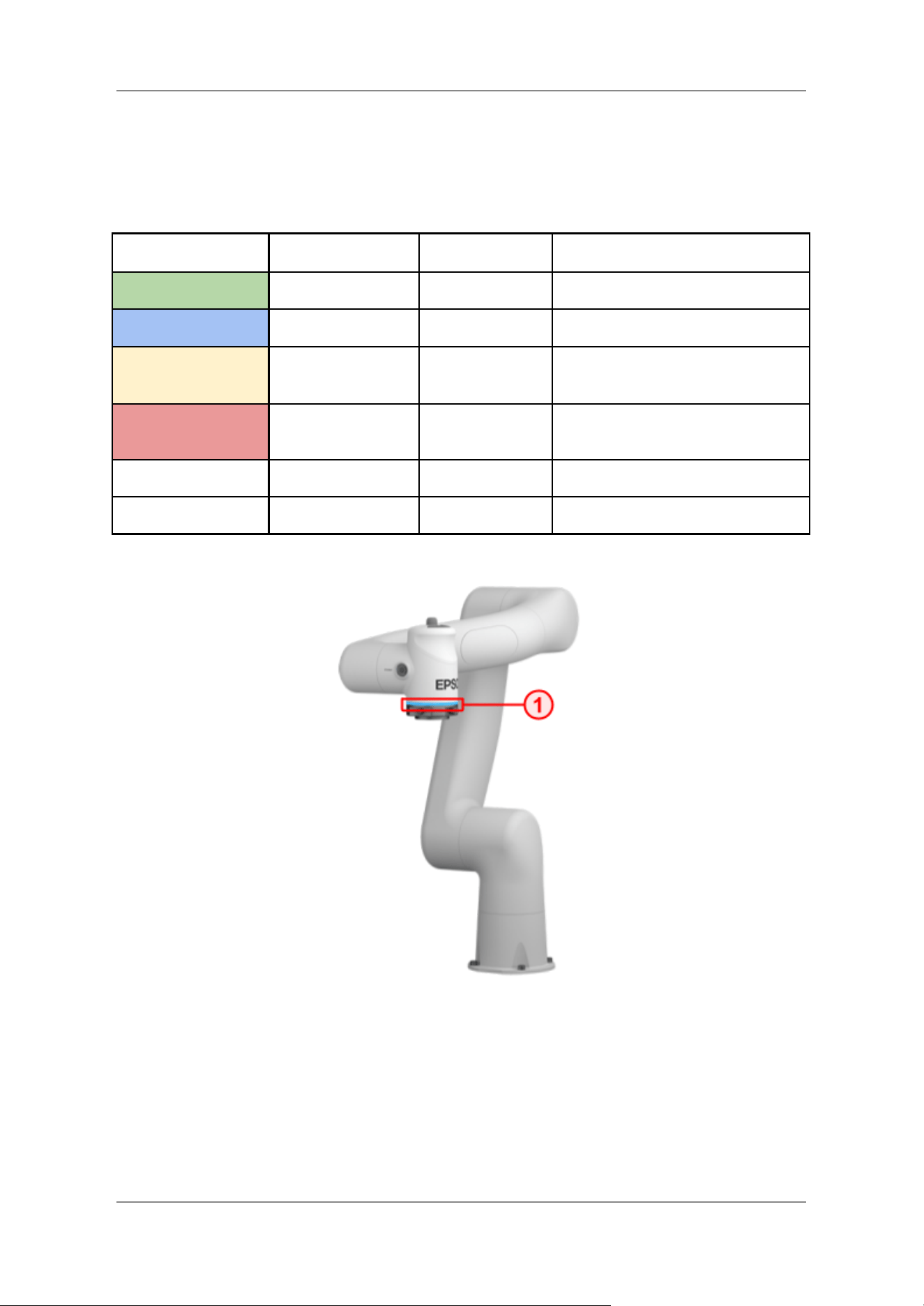
The colour of the LED ring at the interface indicates the operation mode of AX Portal.
LED status
Operation Mode
Motor Power
Description
Green
Auto mode
On
–
Blue
Manual mode
On
–
Yellow
Any
On
Any safety feature active (e.g. SS2
Protective Stop, collision)
Red
Safe torque off
Off
Stop due to safety function or error
(e.g. emergency stop)
Blinking (any color)
Any
On
Hand-guided control active
Light off
Powered off
Off
–
LED Status Ring (1. LED Ring)
33
Collaborative Robot 6-Axis Robots AX6 - Manual
3.6 Control Buttons
WARNING
Do not use the customisable user keys (I and II) to trigger fast movements
or other potentially dangerous functions.
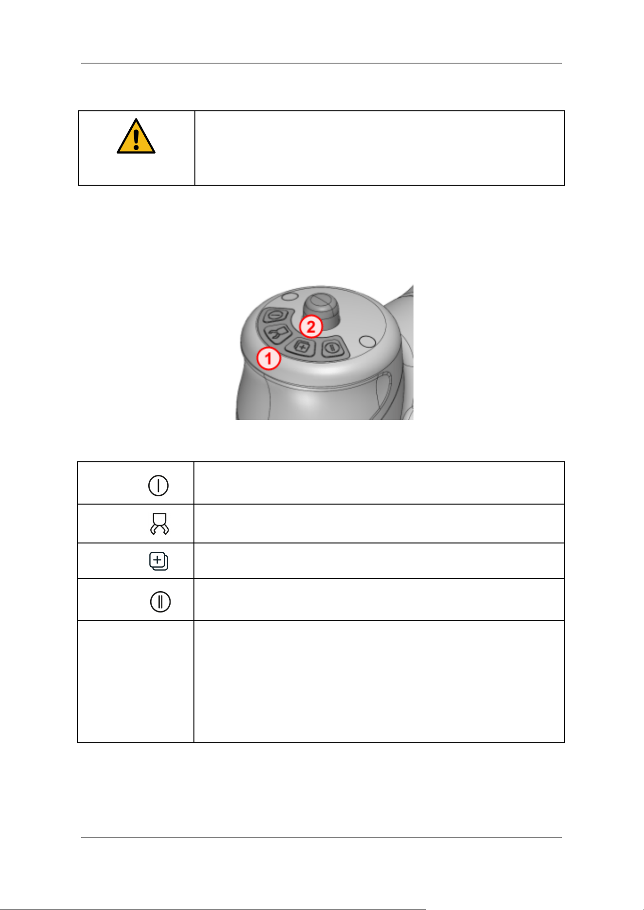
There are four control buttons and a button for the hand-guided mode (“hand-guided control button”)
on link 5–6. Two of the control buttons are predefined. The other two buttons are customisable, see
the “AX Portal User's Guide”, and can be used to run functions of AX portal.
1. Control buttons, 2. Hand-guided control HGC button
I
User-defined.
Gripper
If a gripper is configured, it can be opened and closed with this button.
Teach
Poses can be recorded with this button.
II
User-defined.
Hand-guided
control button
This button has three positions: not pressed, pressed to the middle and
pressed all the way down:
● Pressing the button to the middle position puts the robot into
hand-guided mode.
● If it is pressed all the way down, the robot stops immediately.
The button meets performance level d (TÜV: EN IEC 60947-5-8:2021).
34

Collaborative Robot 6-Axis Robots AX6 - Manual
4. End-Effector Interfaces
35
Collaborative Robot 6-Axis Robots AX6 - Manual
4.1 Introduction
The AX series is compatible with a wide range of grippers. The mechanical ISO interface specified in
more detail below and the electrical M8 connections as well as the air connections are supported by a
wide range of grippers. Where no standard product is available, customised solutions can be
developed by the robot customer.
4.2 Weight and Inertia Settings
Note that the weight and inertia of the mounted end effector must be set in AX Portal. See “AX Portal
User’s Guide”.
WARNING
Always update the gripper settings in AX portal after mounting or
removing an end-effector. Ignoring this can lead to malfunctions, in
particular unexpected movements in hand-guided mode, and to injuries or
damage to the robot system.
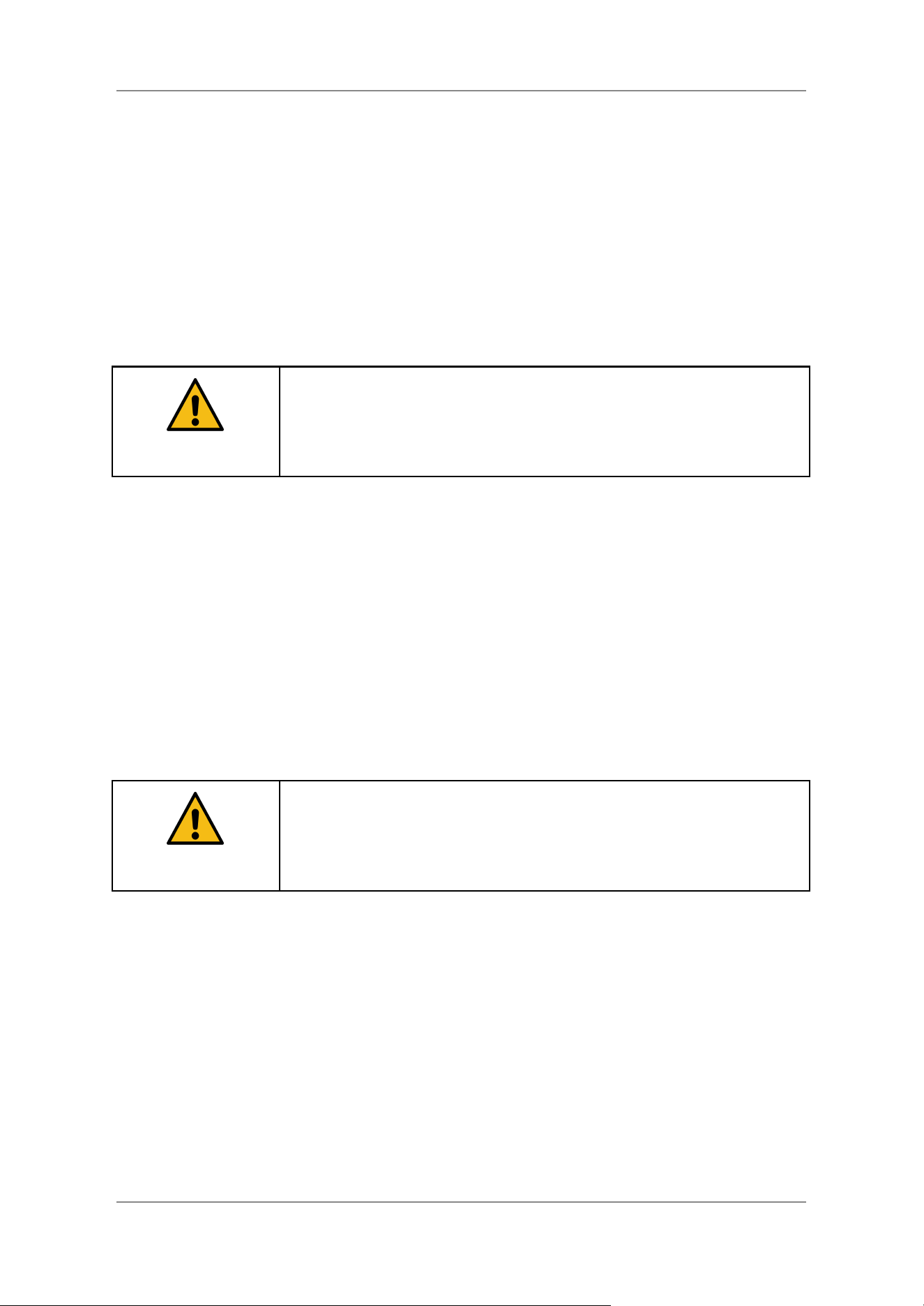
4.3 Mechanical End-Effector Interface
The end-effector interface represents the interface which allows attaching many standard grippers and
other end-effectors. An ISO interface (ISO 9409-1, size 50-4-M6) is available for mounting an
end-effector. Using an end effector, please consider the following:
● Use M6 screws that comply with strength class 8.8 of the ISO 898-1 standard.
● Make sure that there is a thread engagement of at least 10 mm.
● Do not exceed a tightening torque of 6 Nm and check the user manual of your end-effector, as
some end effectors can only withstand lower tightening torques
The drawing below shows the end-effector interface.
CAUTION
Only operate the robot with a properly mounted end tool. Otherwise, the
tool could detach from the robot, which could cause material damage or
injury.
36
Collaborative Robot 6-Axis Robots AX6 - Manual
End-effector interface.
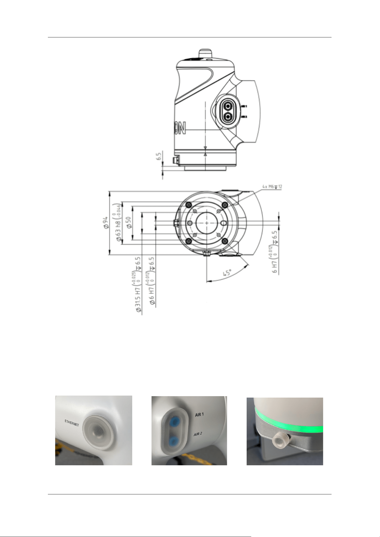
4.4 Connector Protectors
There are rubber protectors for the air, Ethernet and on each I/O connector on link 5–6 and the
end-effector interface.
Ethernet connector protector.
Air connector protector.
I/O connector protector.
37
Collaborative Robot 6-Axis Robots AX6 - Manual
CAUTION
Note that the rubber protectors must be installed when no connectors are
attached to keep the collaborative functionality of the robot. Using the
manipulator as a collaborative robot without the protectors can lead to
injury.
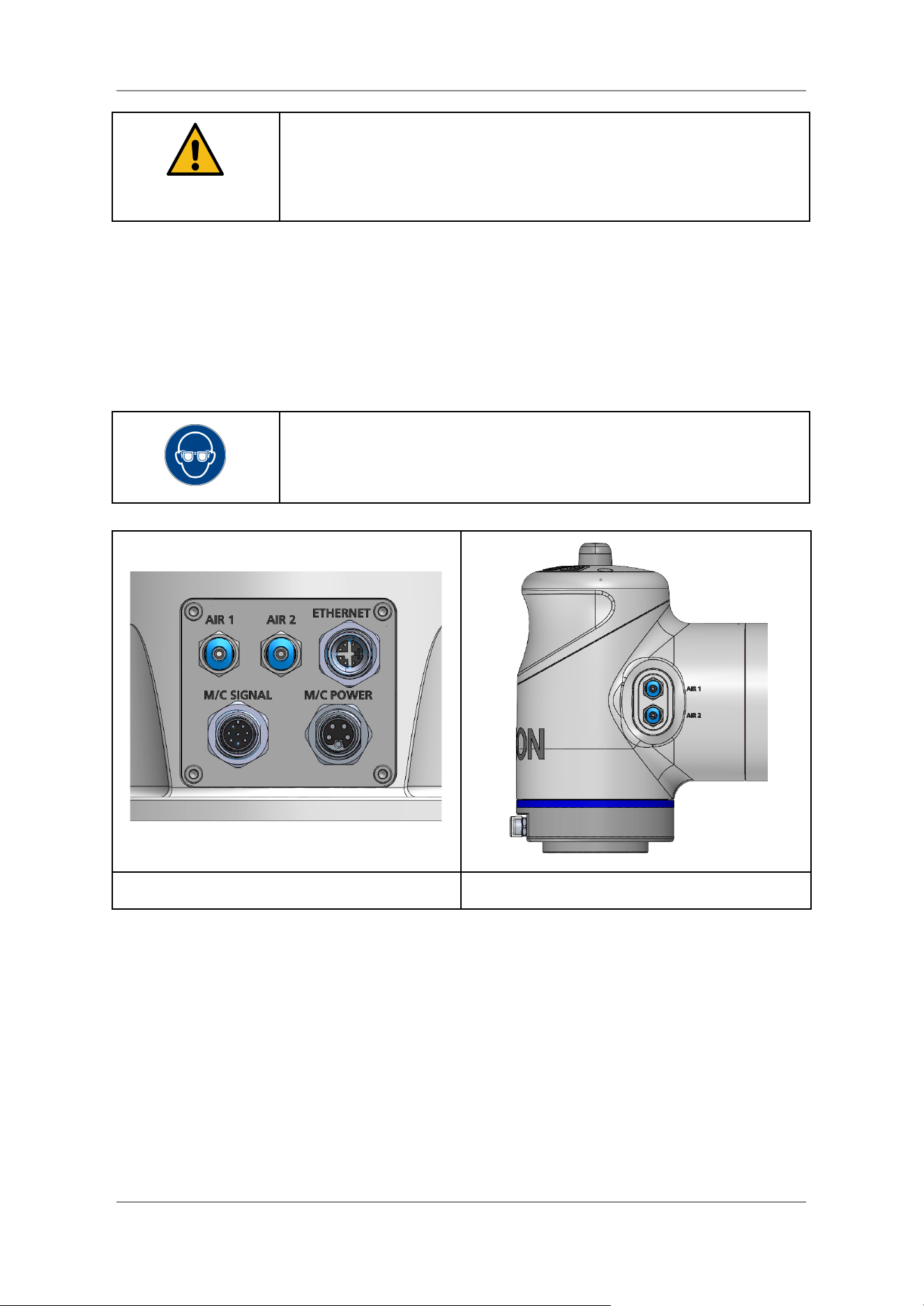
4.5 Air Connectors
There are two air tubes inside the manipulator that lead from the base to the end-effector interface.
The connector size is for 4 mm tubes; the hoses in the manipulator are 3 mm (inner diameter 2 mm).
They might be used for vacuum or compressed air feedthrough.
Do not exceed the maximum pressure of 6 bar (0.6 MPa, 6.11 kgf/cm
2
).
Wear safety glasses when using the air tubes.
Air connectors at the base.
Air connectors at the end tool interface.
38
Collaborative Robot 6-Axis Robots AX6 - Manual
4.6 Electrical Interface to End-Effector (Tool I/O)
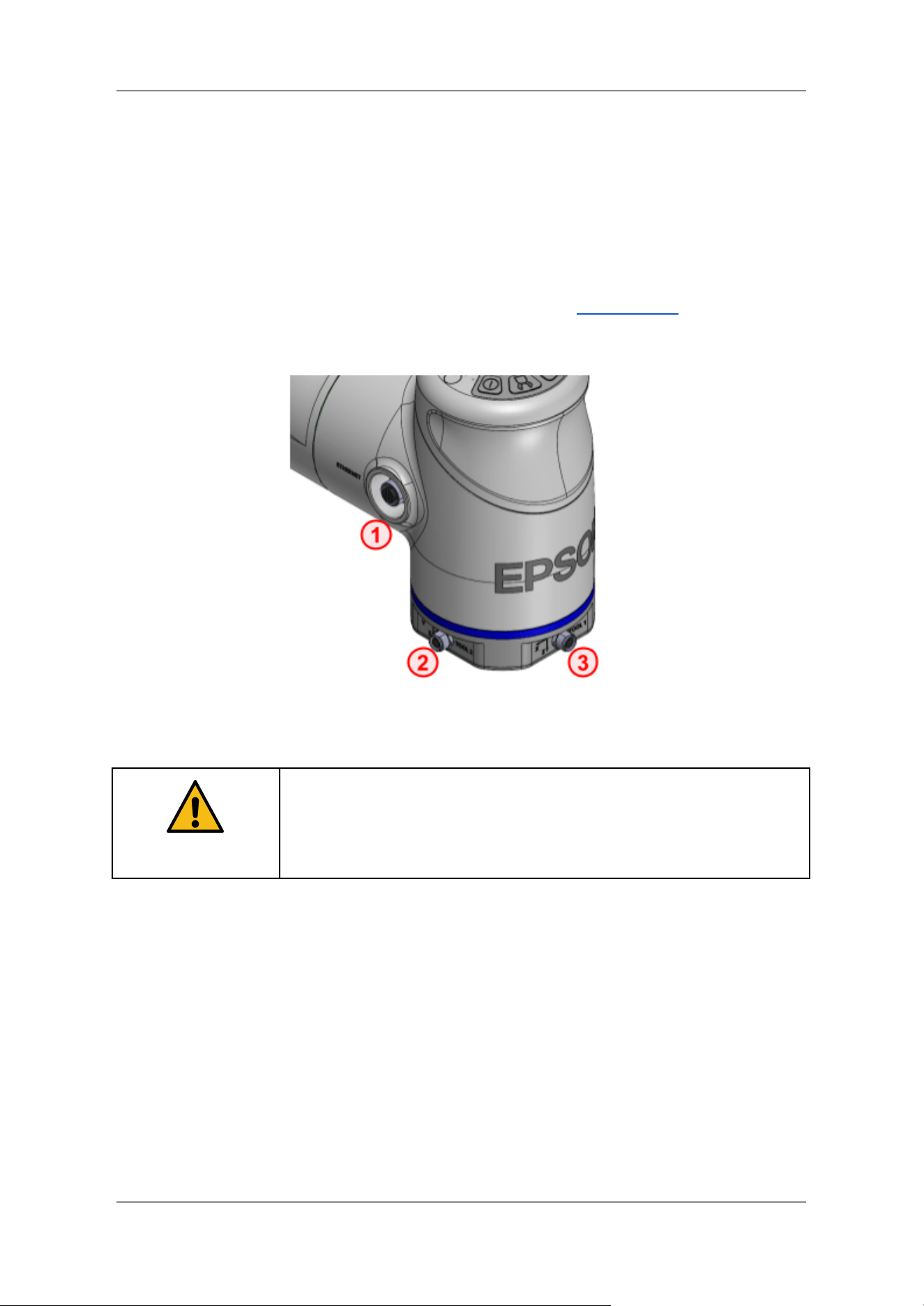
4.6.1 Introduction
The following electrical connections are available on the end tool interface and on link 5–6 for
connecting end effectors (see also picture below):
● Tool 1 and Tool 2: Digital and analogue inputs and outputs, 24 V power supply. See next
section.
● Ethernet line running from the base to link 5–6. See section Ethernet Line.
Connectors at end-effector interface.
1. Ethernet, 2. Tool 1, 3. Tool 2
CAUTION
Be aware that wrong usage of the I/O can damage the robot. Do not reverse
the polarity of the digital or analog I/Os or exceed any current or voltage
limitations.
39
Collaborative Robot 6-Axis Robots AX6 - Manual
4.6.2 Tool Connector Type and Pin Assignment
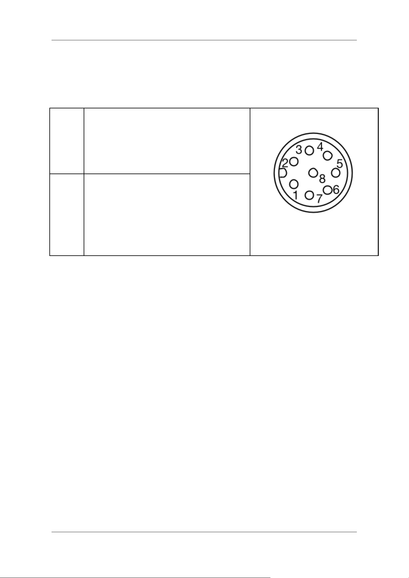
The following connector type is used:
● The Tool connectors are type M8, A-code, 8 pin, female. Ordering information for a suitable
cable can be found in the table below.
Tool 1
1: Analog I/O 2
2: Analog I/O 1
3: Digital Out 2
4: Digital Out 1
5: 24 V
6: Digital In 2
7: Digital In 1
8: GND
Connector ref.: Same Sky
CDM809-08A-FW-F010-050-67
Mating cable ref.: Same Sky
CDM817-08A-01MRA-1M-67
Tool 2
1: Analog I/O 4
2: Analog I/O 3
3: Digital Out 4
4: Digital Out 3
5: 24 V
6: Digital In 4
7: Digital In 3
8: GND
4.6.3 I/O Configuration
In AX Portal, the analog and digital IOs can be configured via the “I/Os Configuration” panel before
powering up the robot.
The digital inputs can be either configured as “Input” (default, pull-downs enabled) or “Input
(Pull-Up)” which disables the switchable pull-down resistors.
Each of the analog I/O pins is a configurable circuit that can function as either an input or an output
and can be further configured to operate in either voltage or current mode. This results in the
following modes:
● Input – voltage mode
● Input – current mode
● Output – voltage mode
● Output – current mode
Specifications and example connection diagrams are provided in the next sections.
40
Collaborative Robot 6-Axis Robots AX6 - Manual
4.6.4 I/O Supply
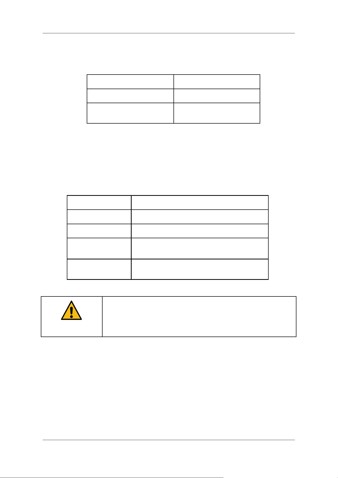
The 24 V and GND pins are used to supply power to the circuits and devices connected to the digital
and analogue inputs and outputs.
Output Voltage
24 V
Max. Output per Pin
1 A (1.1 A OCP)
Max. Total Current
2 A (sum of all pins incl.
Digital Outputs)
4.6.5 Digital Inputs (Tool I/O)
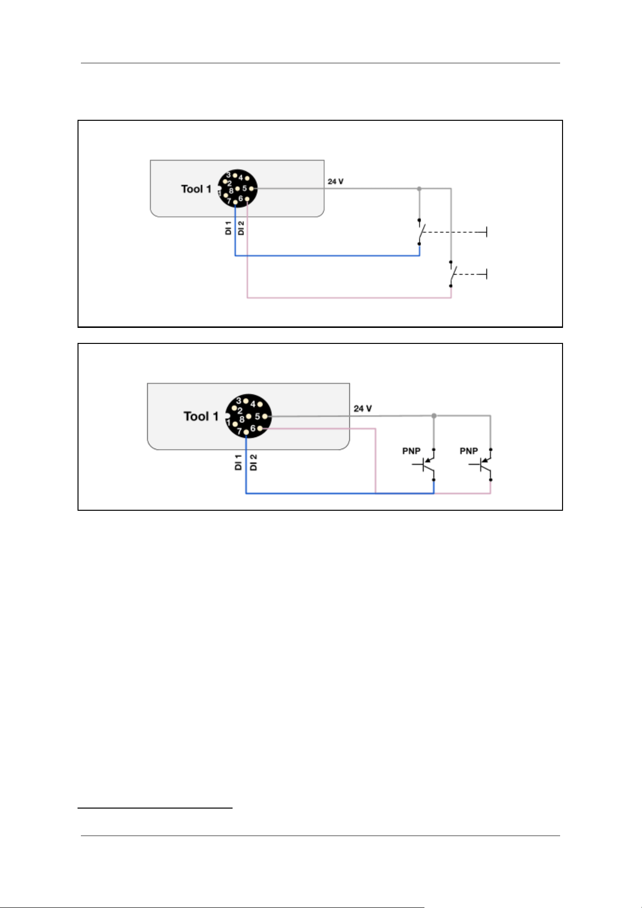
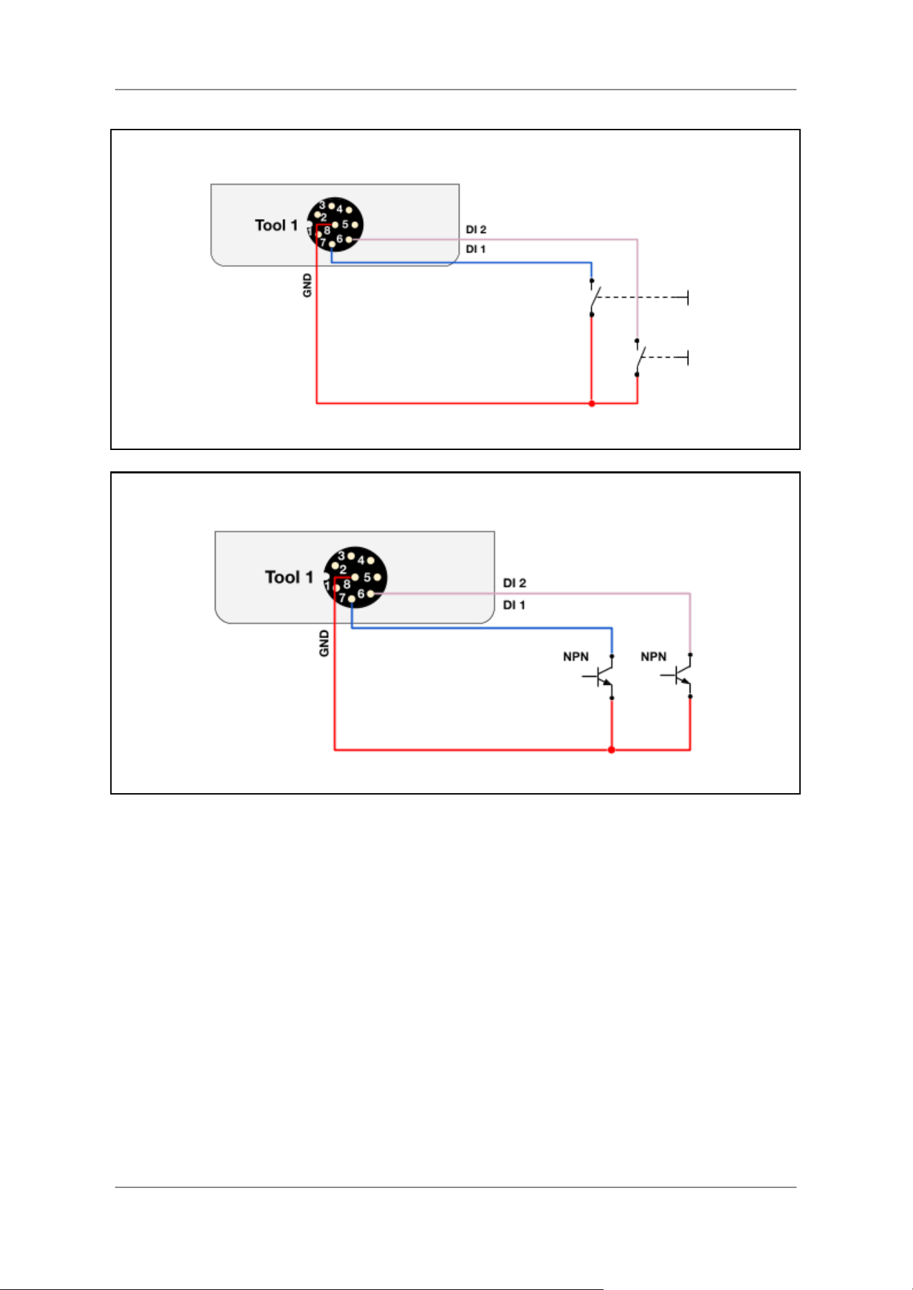
Each of the digital inputs is a high impedance circuit with a fixed pull-up and switchable pull-down
resistor configurations (default is pull-down enabled). The inputs allow for both PNP and NPN type
sensors to be used. Example connection diagrams for each of the above configurations are shown
below. Note that each of the inputs can be used differently (e.g. Digital In 1 as pull-down enabled and
Digital In 2 as pull-down disabled).
Max Input Voltage
24 V
ON Voltage
≥ 3 V
OFF Voltage
< 1 V
Input Resistance
14.7 kΩ (pull-down enabled)
334 kΩ (pull-down disabled)
Input Current
2.17 mA at 24 V (pull-down enabled)
1.23 mA at 24 V (pull-down disabled)
CAUTION
The 24 V and GND connections of the indicated external device should be
sourced from the corresponding pins provided from the respective Tool I/O
connector used.
41
Collaborative Robot 6-Axis Robots AX6 - Manual
Note: The following examples use connector “Tool 1” but connector “Tool 2” has the exact same
functionality.
Example with Two Buttons (Pull-Down Enabled)
4
Example with Two PNP Type Sensors (Pull-Down Enabled)
4
Please note that the wire colors specified in this document comply with the widely used DIN 47100 standard.
42
Collaborative Robot 6-Axis Robots AX6 - Manual
Example with Two Buttons (Pull-Down Disabled)
Example with Two NPN Type Sensors (Pull-Down Disabled)
43
Collaborative Robot 6-Axis Robots AX6 - Manual
4.6.6 Digital Outputs (Tool I/O)
Output driver
Half-bridge power driver
Output Voltage
24 V
Maximum Output Current
(Sourcing or Sinking)
1 A (1.1 A OCP)
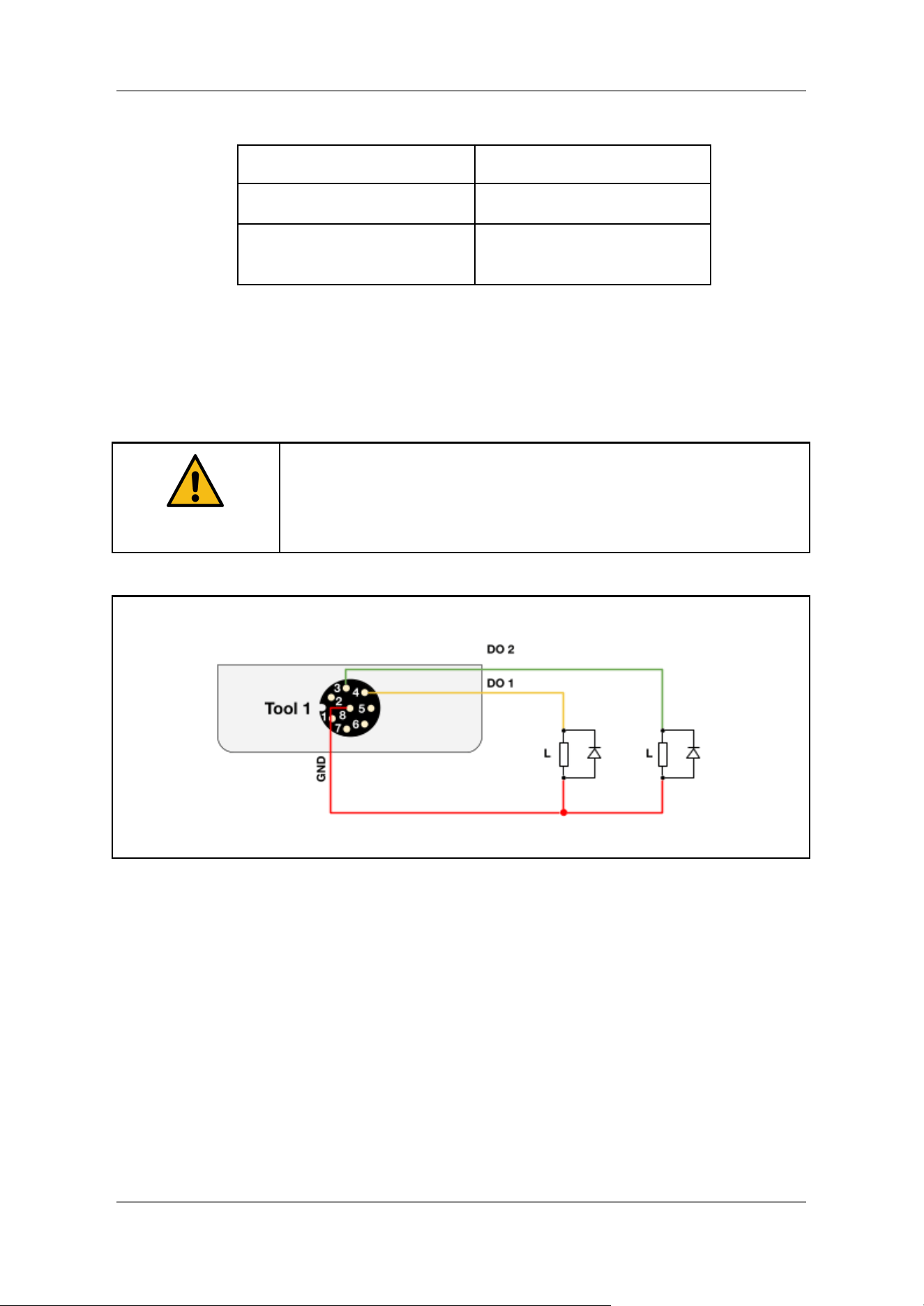
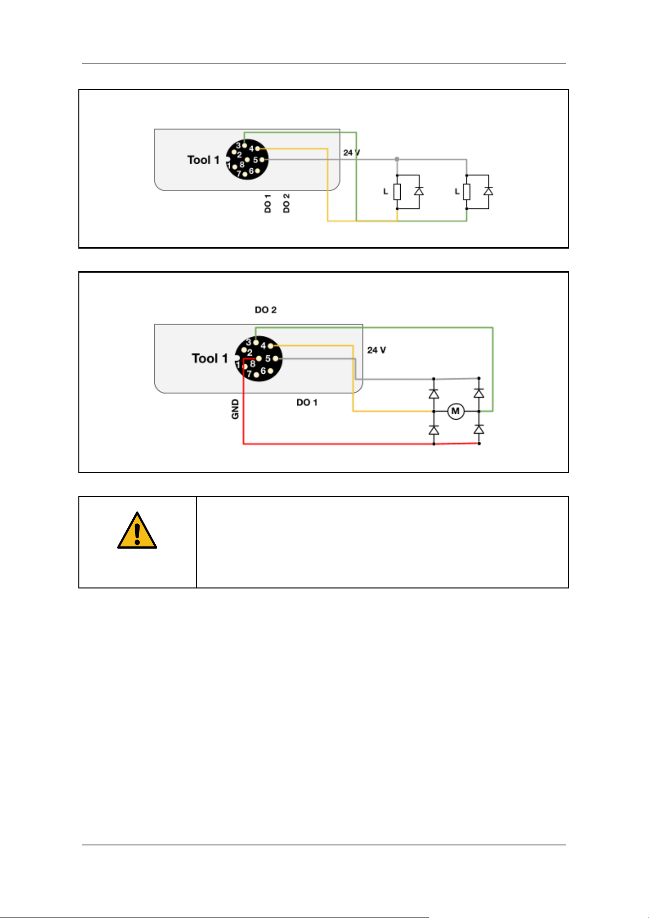
Each of the digital outputs is a current limited, push-pull, half-bridge power driver. The driver allows
operation in source mode (PNP type), sink mode (NPN type) and a full-bridge type configuration
using two outputs. Example connection diagrams for each of the above configurations are shown
below. The default state of the digital outputs is LOW. For the configuration, see “AX Portal User’s
Guide”.
CAUTION
The 24 V and GND connections of the indicated external device should be
sourced from the corresponding pins provided from the respective Tool I/O
connector used.
Example with Two Connected Loads (Source Mode – PNP)
44
Collaborative Robot 6-Axis Robots AX6 - Manual
Example with Two Connected Loads (Sink Mode – NPN)
Example with a Connected Motor (Full Bridge Mode)
CAUTION
Warning about DC Motor Usage
For the specific usage of inductive loads such as e.g. brushed DC motors,
relays or solenoids, external flyback diodes should be added to contain the
back-EMF and re-circulate any excess inertial energy when the motor is
switched off.
45
Collaborative Robot 6-Axis Robots AX6 - Manual
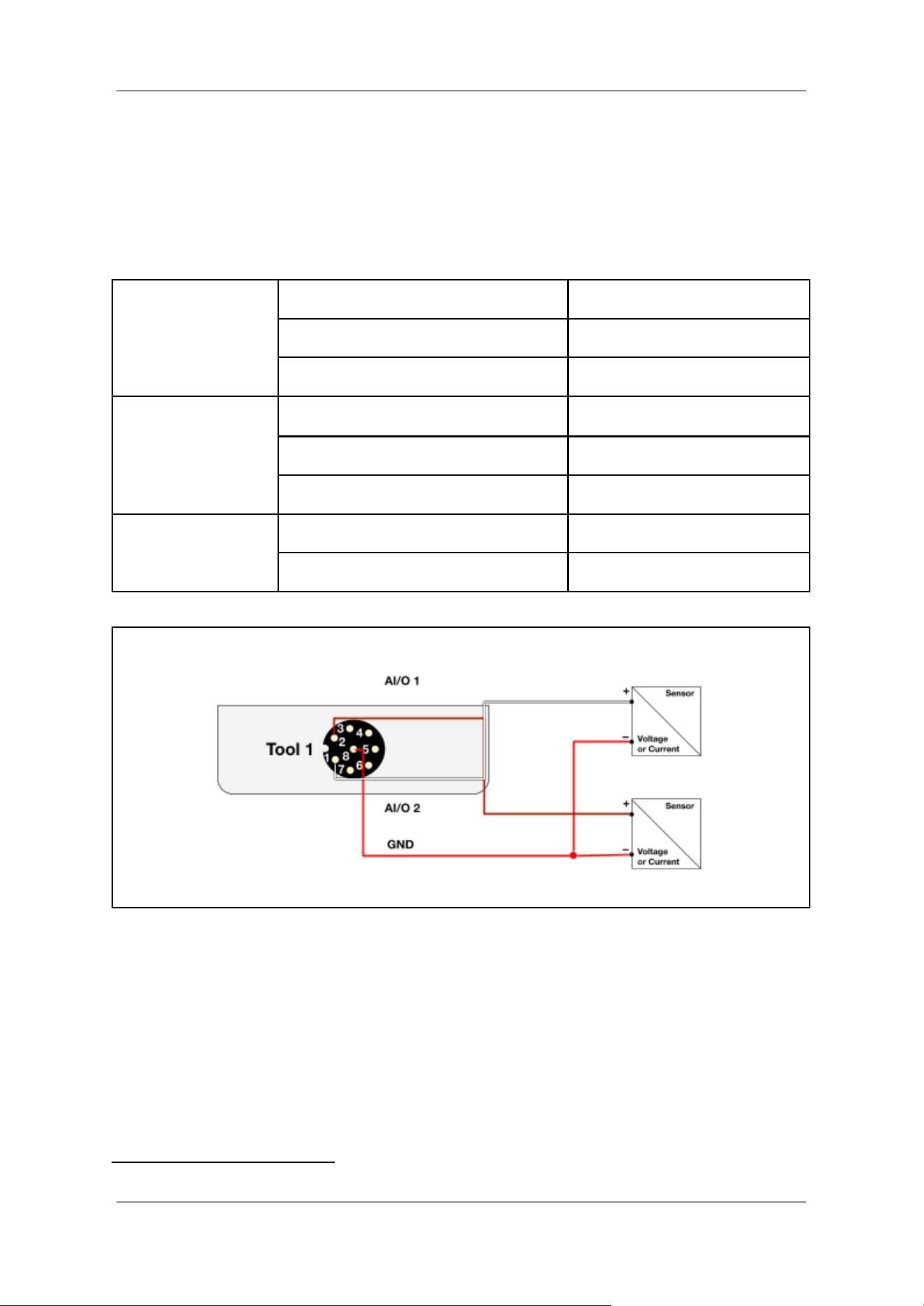
4.6.7 Analog Inputs (Tool I/O)
Analog Tool I/Os can be configured as inputs in voltage or current mode. In voltage mode, analog
readings in the range of 0–10 V are possible. In current mode, a sense resistor in the circuit is
activated which allows current readings in the range of 4–20 mA. An example connection diagram is
shown below, which is valid both for current and voltage mode.
Analog Input Configuration
General
Specifications
Maximum sampling frequency
20 Hz
Maximum input voltage
10 V
Sampling resolution
12 bit
Voltage Mode
Input voltage range
0–10 V
Input current consumption
< 1 mA
Minimum local impedance
≥ 100 kΩ
Current Mode
Input current range
4–20 mA
5
Sense resistance
135 Ω
Example with Two Connected Analog Sensors (Voltage or Current Mode)
5
Operation within the 0–20 mA range is permitted, but fault detection is not available.
46
Collaborative Robot 6-Axis Robots AX6 - Manual
4.6.8 Analog Outputs (Tool I/O)
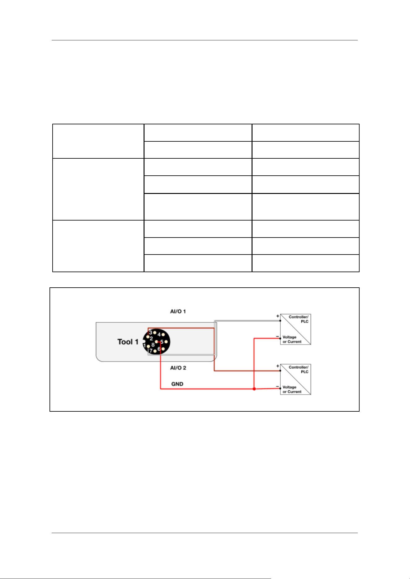
Analog Tool I/Os can be configured as outputs in voltage or current mode. In voltage mode, analog
outputs in the range of 0-10V are possible. In current mode, an output in the range of 0-20 mA can be
generated. An example connection diagram is shown below, which is valid both for current and
voltage mode.
Analog Output Configuration
General Specifications
Maximum output frequency
20 Hz
Output resolution
12 bit
Voltage Mode
Output voltage range
0–10 V
Maximum output current
1 mA
Minimum remote
impedance
≥ 50 kΩ
≥ 100 kΩ recommended
Current Mode
Maximum output voltage
10 V
Output current range
0–20 mA
Output load resistance
< 300 Ω
Example with Two Connected Analog Sensors (Voltage or Current Mode)
47
Collaborative Robot 6-Axis Robots AX6 - Manual
4.7 Ethernet Line
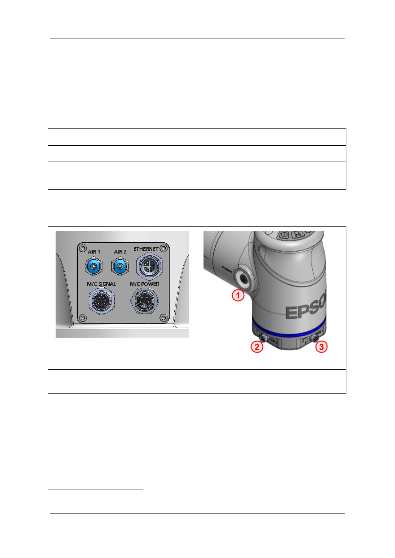
The Ethernet goes through the robot from the base to the link 5–6:
The connector type is:
● The Ethernet connector is type M12, X-code, 8 pin, female.
The table below shows the properties of the Ethernet line.
Category
Cat 5e
Data Rate
1 Gbit/s
Power Over Ethernet Support
Supports power over Ethernet (PoE) up to IEEE
802.3at (Type 2)
6
Make sure that the joint 6 angle is limited when operating the manipulator with plugged Ethernet
cables on Link 5–6.
Ethernet connector at the base.
Ethernet connector at link 5–6.
1. Ethernet, 2. Tool 1, 3. Tool 2
6
An additional PoE injector is required to supply power over Ethernet devices (not included in the scope of
delivery).
48

Collaborative Robot 6-Axis Robots AX6 - Manual
5. Maintenance
49
Collaborative Robot 6-Axis Robots AX6 - Manual
5.1 Introduction
The AX6 robot requires very little maintenance. The steps are divided into maintenance and
inspection points. The latter are essential for the safe operation of the robot system.
Please note that this section exclusively refers to the manipulator and not to the system in which it is
integrated. The integrator must define additional maintenance and inspection points for the system in
which the robot is integrated.
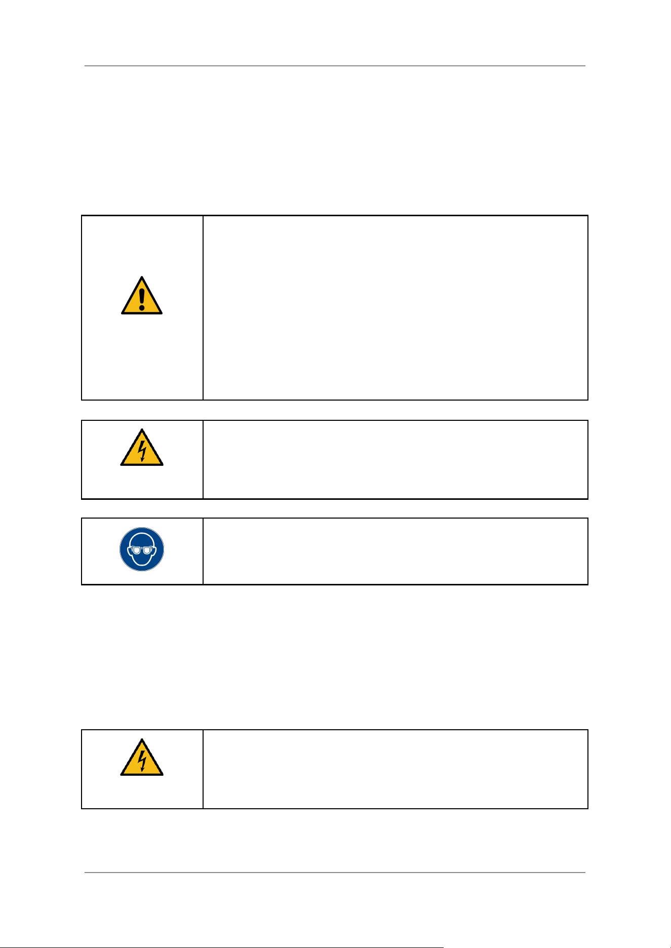
WARNING
Please note the following points before performing maintenance on the
robot system:
● Switch off the system for any maintenance work. Secure the
system against unintentional switching on by third parties, for
example with a ‘Do Not Turn On’ sign. Maintenance work while
the system is running can result in serious injury or death.
● Only carry out the maintenance work listed in this chapter. Under
no circumstances should you attempt to repair a defective robot
system yourself. Improperly performed repairs can result in serious
injury or death.
WARNING
Do not open the manipulator or the controller under any circumstances.
This may result in electric shock.
Wear safety goggles when you need to remove the air hoses during
maintenance work – even if the air supply has been turned off.
5.2 Cleaning of the Manipulator and Controller
Clean the outer shell of the robot and the controller if it is dirty:
● Wipe away any dirt on the manipulator with a soft microfibre cloth. For heavy soiling or
disinfection, you can moisten the cloth with 70% isopropanol. Be careful not to scratch the
paint of the manipulator.
WARNING
Never spray any liquid onto the controller, including cleaning agents. If
liquid is sprayed onto the controller, it may result in an electric shock.
50
Collaborative Robot 6-Axis Robots AX6 - Manual
5.3 Maintenance Inspection
WARNING
These checkpoints must be observed to ensure that the robot can be
operated safely in the long term. Failure to observe the checkpoints may
result in functional failure, injury or even death.
Check the points listed below.
Inspection Item
Frequency
Location
Method
Loose Screws
Monthly /
250 h
7
Screws that secure
● the manipulator
● the end effector
● the earth cables
Use a torque wrench to check that
the screws/nuts tightened.
Loose
Connectors
Monthly /
250 h
External electrical and
air connectors on
● Base
● Link 5–6
● Tool flange
Check that connectors are not loose.
When the connectors are loose,
reattach them properly and check
them again.
External
Defects
Weekly
Manipulator
Clean the manipulator if it is dirty,
see section “Cleaning of the
Manipulator and Controller”.
External Cables
Check the external cables (e.g.
supply cables from controller,
periphery cables) and the air tubes
for external defects. Immediately
replace defective cables and air
tubes.
Brake
Operation
Monthly /
250 h
Joint 1 to 6 brake
Power-off the robot and check
whether the brakes engage when the
manipulator is moved by hand. If the
brakes are working correctly, each
axis can only be moved a very short
distance before the brakes stop the
movement with a clicking sound, or
the brakes block the axis completely.
If it is possible to move the
manipulator with little effort, the
brakes are faulty.
7
If the robot is powered up for more than 250/h per month, execute all monthly items every 250 h.
51
Collaborative Robot 6-Axis Robots AX6 - Manual
Please also check whether the
manipulator moves downwards
under its own weight when switched
off.
Vibration and
Sound
Monthly /
250 h
–
Check the robot for abnormal
operating noises or vibrations (e.g.
for a loud gearbox).
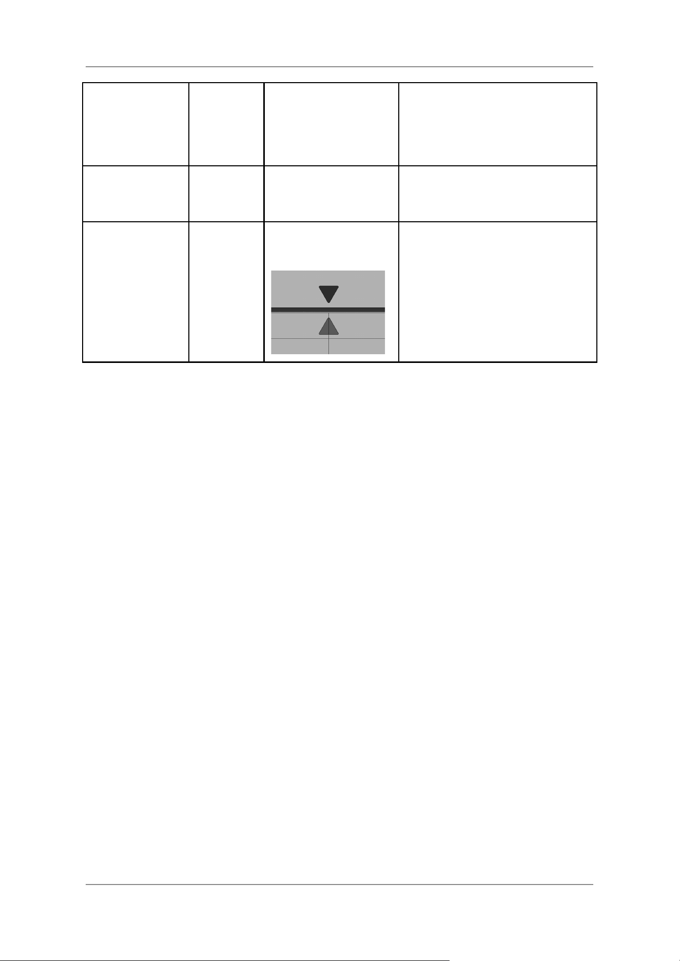
Zero Position
Yearly
Zero point marks on
joint 1 to joint 6.
Move every joint to 0° and check if
the zero marks align.
5.4 Repair
The robot has been designed for ease of repair. Repairs shall be performed by properly trained service
engineers. For details, refer to the “AX6 / RC-A101 Safety Manual” manual.
52