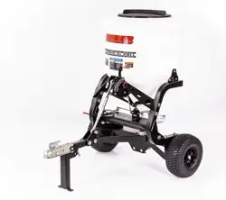
1/30/2020
HOBBY FARM PRO
TOW BEHIND
S
PREADER
OWNER’S
MANUAL
SWISHER ACQUISITION INC.
1602 CORPORATE DRIVE, WARRENSBURG, MISSOURI 64093
PHONE (660) 747-8183 FAX (660) 747-8650
Uncrating
As
sembly
Operation
Service and Adjustment
Repair Parts
www.swisherinc.com
MODEL NO.
S
TARTING SERIAL #:
L119-247001
SPREADER#
22000
21999 REV 19-247
Re
ad and follow all
Safety Precautions
and Instructions
before operating this
equipment.
IMPORTANT
ade I The
USA
of US and Global Parts

The manufacturer’s warranty to the original consumer purchaser is: This
p
roduct is free from defects in materials and workmanship for the period's shown
below beginning from the date of purchase by the original consumer purchaser.
We will repair or replace, at our discretion, parts found to be defective due to
materials or workmanship. This warranty is subject to the following limitations
and exclusions:
1) Commercial &
Consumer Use This product has a 1 year Limited Commercial and Consumer
warranty from the date of purchase.
2) Limitation This warranty applies only to products, which have been properly
assembled, adjusted, and operated in accordance with the
instructions contained within this manual. This warranty does not
apply to any product of Swisher that has been subject to alteration,
misuse, abuse, improper assembly or installation, shipping
damage, or to normal wear of the product.
3) Exclusions Excluded from this warranty are normal wear, normal adjustments,
and normal maintenance.
In the event you have a claim under this warranty, you must return the product to an
authorized service dealer. All transportation charges, damage, or loss incurred during
transportation of parts submitted for replacement or repair under this warranty shall be
borne by the purchaser. Should you have any questions concerning this warranty,
please contact us toll-free at 1-800-222-8183. The model number, serial number, date of
purchase, and the name of the authorized Swisher dealer from whom you purchased the
Spreader will be needed before any warranty claim can be processed.
THIS WARRANTY DOES NOT APPLY TO ANY INCIDENTAL OR CONSEQUENTIAL
DAMAGES AND ANY IMPLIED WARRANTIES ARE LIMITED TO THE SAME TIME PERIODS
STATED HEREIN FOR ALL EXPRESSED WARRANTIES. Some states do not allow the
limitation of consequential damages or limitations on how long an implied warranty may
last, so the above limitations or exclusions may not apply to you. This warranty gives
you specific legal rights and you may have other rights, which vary from state-to-state.
This is a limited warranty as defined by the Magnuson-Moss Act of 1975.
2
LIMITED WARRANTY

ү
3
• SAFETY PRECAUTIONS…………………………………………..………………………….……... 4
• SPECIFICATIONS…………………………………………………………….………………………. 5
• SAFETY AND OPERATION DECALS………………………………......………..………..…….... 6
• KNOW YOUR SPREADER.……………………………………………………...…………………… 7
• ASSEMBLY PARTS…………...…………………………….....……………….….………............... 8
• UNCRATING …….…………………………………………………………………………….……… 9
• ASSEMBLY …….……………………………………………………………………………….………10
• GETTING STARTED ……………………………………………………………...……….…………11
• TOW VEHICLE SET UP……………………………………………………………...……….…..12-13
• CONTROL OPERATIONS……………………………………………………………...………..….14
• CONTROL CALIBRATION……………………………………………………………...………15-16
• SPREAD PATTERN ADJUSTMENT………………………………………………………...………17
• GENERAL OPERATIONS………………..…………………..………………………...…….....18-19
– GENERAL RECOMMENDATIONS
– GETTING STARTED
– SPREADING RECOMMENDATIONS
– STARTING SPINNER DISC
– BEFORE YOU START SPREADING
– SPREADING IN FIELD
– SPREAD ZONE COVERAGE
• SPREADER MAINTENANCE……..………………………………...…...…………………......... 20
– GENERAL RECOMMENDATIONS
– BEFORE EACH SEASON
– BEFORE EACH USE
– AFTER EACH USE
• CLEANING GUIDELINES…………………………………………….……..….……………….....21
• TROUBLESHOOTING…………………………………………….……..….……………….......... 22
• PARTS DIAGRAMS …….…………………………………….………......……………………..23-31
– FRAME ASSEMBLY
– GEARBOX ASSEMBLY
– TIRE & AXLE ASSEMBLY
– HITCH ASSEMBLY
– SPINNER DISC ASSEMBLY
– DEBRIS GUARD
– OFFSET GATE CONTROL
– FLOW GATE CONTROL
– CONTROL ASSEMBLY
– HOPPER ASSEMBLY
– HOPPER MOUNTING ASSEMBLY
• CALCULATING MATERIAL FLOW……………………………….....………………..…..........32
• SPREADER LOG NOTES………………………………………………………….…………….33-34
TABLE OF CONTENTSTABLE OF CONTENTS
ү
This Safety Alert Symbol indicates important messages in this
ma
nual. When you see this symbol, carefully read the message
that follows and be alert to the possibility of personal injury.
Read this manual completely. This machine can injure hands and legs, and throw objects.
Failure to observe the following safety instructions could result in serious injury or death.
4
• Read the manual. Learn to operate this machine safely.
• Keep all shields and guards in place.
• Understand the speed, steering and stability of this machine. Know the positions and operations
of all controls before you operate this machine. Check all of the controls in a safe area before
starting to work with this machine.
• Allow only responsible adults who are familiar with these instructions to operate this machine.
Never allow children to operate this machine.
• Be sure the area is clear of other people before spreading. Stop the machine if anyone enters the
spreading area. Children are often attracted to the machine and the spreading activity.
Never assume that children will remain where you last saw them. Keep children under the
watchful care of another responsible adult.
• No riders!
• Do not put hands or feet near or under rotating parts.
• Do not spread in reverse. Always look down and behind before and during backing.
• Disconnect Axle Pin when not spreading material.
• Watch for traffic when operating near or crossing roadways.
• Do not operate the Spreader if it has been dropped or damaged in any manner or if the Spreader
vibrates excessively. Excessive vibration is an indication of damage. Repair Spreader as
necessary.
• Use proper handling procedures for the material you are using. Obey all safety precautions
advised by the material manufacturer.
• Dress properly. Protect skin and body parts from flying material and dust.
• Do not operate the machine while under the influence of alcohol or drugs.
• Do not operate on slopes greater than 15 degrees.
• Stop and inspect the equipment if you strike an object. Repair, if necessary, before resuming.
• Volume of material and weight of material vary by the material’s density. Always pay attention to
the amount of weight you are putting into the Hopper. Do no exceed the 600 lb capacity. Some
materials will reach 600 lbs before the Hopper is full.
• Do not exceed the recommended speed with towing. 5 MPH while spreading/loaded and 15 MPH
while transporting an empty unit.
• Always remove the axle pin when transporting the spreader. Do not travel long distances with a
fully loaded hopper as this will cause the material to compact and can result is poor operation or
equipment damage.
SAFETY PRECAUTIONS
Thank you for choosing Swisher’s Tow-Behind Spreader. Before operating your
Spr
eader, please read, understand and follow all of the safety precautions and
other instructions explained in this manual. As with all power equipment
Spreaders can be potentially dangerous if improperly used.
ү
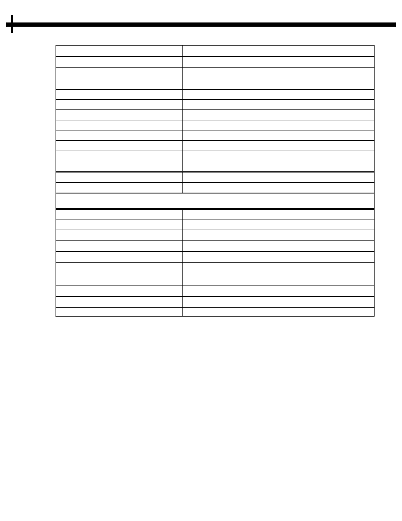
Description
G
earbox
3.3:1 gears, Aluminum Cast Housing
Gearbox Oil
SAE 90W/80W90 ; 12 oz. (.35 lt)
Drive System
Ground Driven, One Drive Wheel
Overall Dimesions
44" L x 44" W x 54" T
Unit Dry Weight
200Lbs. (90.7 Kg)
Spread Orientations
Left, Full & Right
S
preading Width
Dependant on Material; up to 30ft
Hopper Capacity
600 lbs
Towing Speed
15 MPH MAX
Spreading Speed
5 MPH (Flat Ground) 4 MPH Max (Rough Ground)
Tire PSI
20 PSI Recommended (Min. 15 PSI - Max 35 PSI)
Description Part Number
Washer - Plastic, 1/2" ID
21967
Wheel/Tire - 15/650-8
21934
Pin - Drive Axle
21986
Fin - Spinner Disc
21939GV
Agitator Head
21989GV
Agitator Bolt & Nut
NB218 & NB181
Cotter Pin - Agitator Shaft
19036
Agitator Spring
12364
Quick Reference - Maintenance Parts
Note:
•
For other part numbers, refer to the Parts Diagrams on pages 23-31.
5
SPECIFICATIONS

Replace decal immediately if damaged.
O
D33-5MPH DECAL
6
SAFETY AND OPERATION DECALS
21985-GATE SETTING DECAL
OD55 DANGER KEEP AWAY
21916- LEVEL DECAL
2
1915- CAPACITY DECAL
21977- FLYING DEBRIS DECAL
21914- AXLE PIN DECAL
21969- CONTROL OPERATION DECAL
7
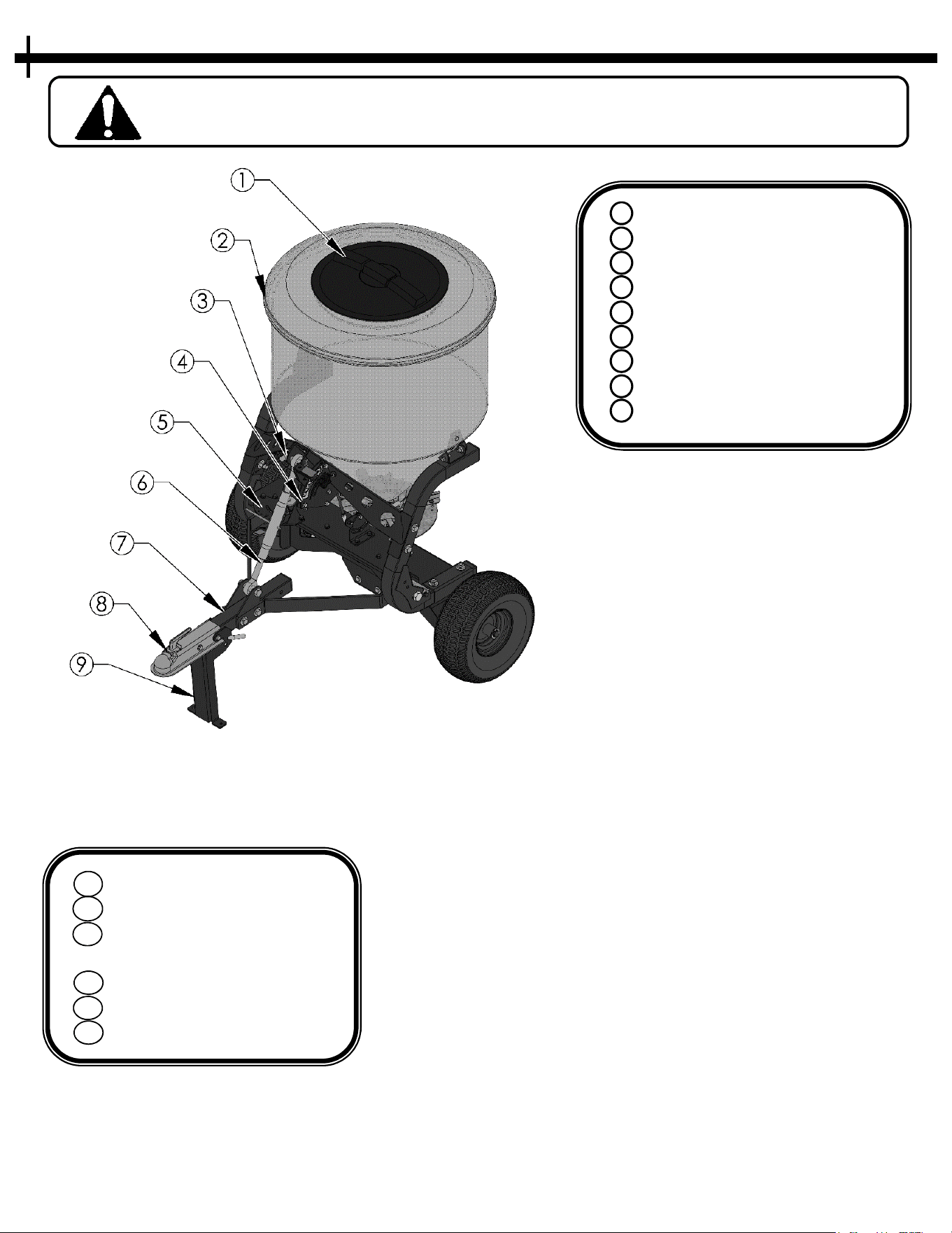
KNOW YOUR SPREADER
It is important to know the features of the Spreader. Please review
t
he entire manual for detailed operational and safety information.
10 Drive Wheel
1
1 Free Wheel
12 Spreader Disc &
Adjustable Fins
13 Removable Axle Pin
14 Gearbox
15 Adjustable Linkages
1 Vented Lid
2
Poly Hopper
3 Removable Link Pin
4 Flow Controls
5 Offset Controls
6 Leveling Link
7 Adjustable Hitch Bar
8 2” Ball Coupler
9 Hitch Stand
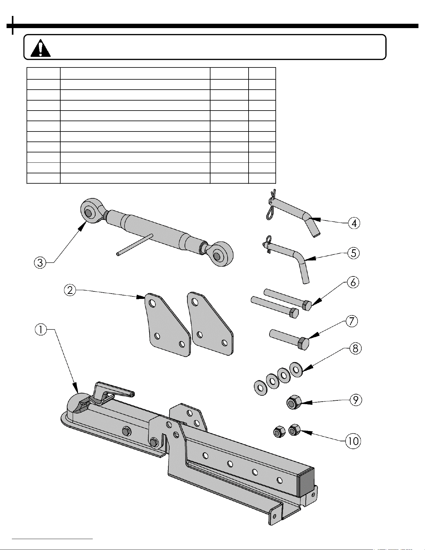
Before assembling the Spreader make sure that all assembly parts are present.
Item # Description Part # Qty
1 Hitch Bar Pre-Assembly - 1
2 Plate - Top Link Hitch Bracket 21951* 2
3 Top Link 21103 1
4 Pin - Bent w/Hair Pin, 5/8 X 3 NB702 1
5 Pin - Bent w/Hair Pin, 1/2 X 3 NB606 1
6 Bolt -1/2-13 X 4" NB132 2
7 Bolt - 5/8-11 X 3" NB699 1
8 Washer - USS Flat, 1/2 NB555 4
9 Nut - 5/8-11 Nylon-Insert Lock 21138 1
10 Nut - 1/2-13 Nylon-Insert Lock NB281 2
8
ASSEMBLY PARTS
When ordering replacement parts
* = USE PAINT CODE: TK=BLACK
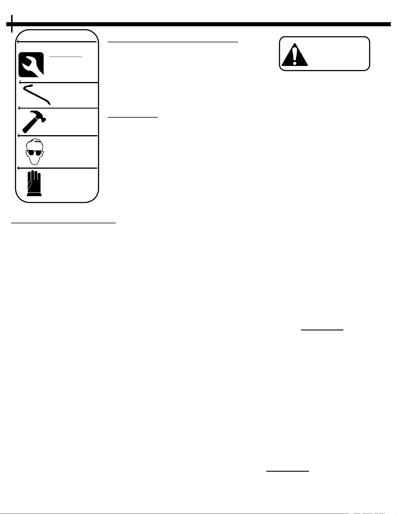
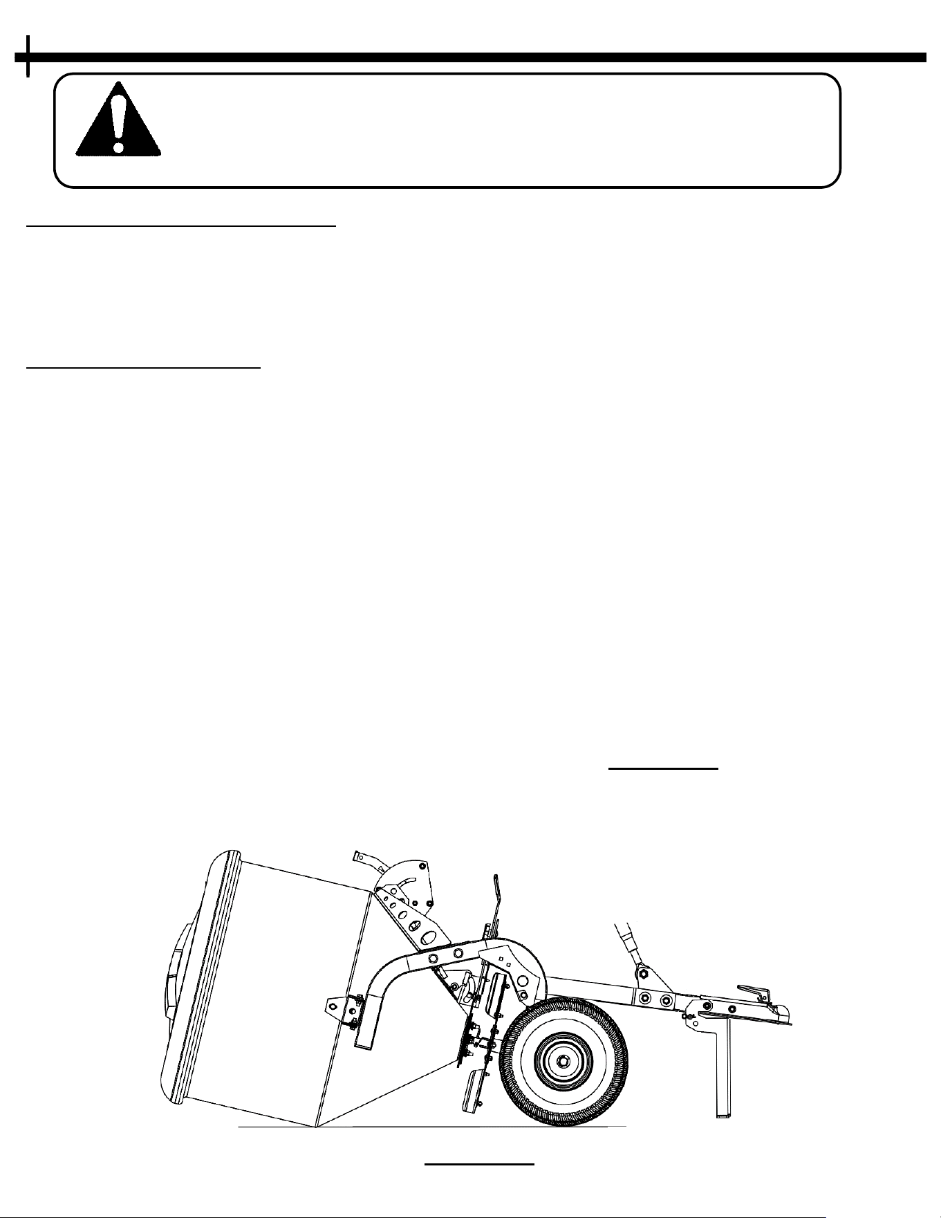
UNCRATING DIRECTIONS
1. Using the required tools, remove the front
p
anel of the crate. The front panel is the
side of the crate that the hitch arms are
facing as shown in FIGURE 9.1. This is the
only side that needs to be removed for
uncrating the unit. The entire crate can be
disassembled if you choose, but it is not
required for assembly.
2. After the front crate panel has been
removed, locate the hitch bars that are
bolted to the wooden block. This bolt will
be removed. See FIGURE 9.2
3. Have a second person hold the spreader
upright when removing this bolt. Once
this bolt is removed the Spreader can
fall forward. Use Caution!
4. Slowly Lower the Unit forward until it is
resting on the hitch arms.
5. Follow the Assembly instructions on page
10.
6. After the unit is assembled, remove the zip
ties holding it to the crate base.
7. Remove the wheel chocks holding the front
of the spreader tires in place.
8. The spreader can now be rolled out of the
crate.
9. Check that all hardware is secure before
using.
9
FIGURE 9.2
UNCRATING
GENERAL RECOMMENDATIONS
• Use at least two people to
u
ncrate & assemble the unit.
The Spreader and its
components are heavy.
• Refer to page 36 for
recommended hardware torque
values.
UNCRATING
• Using a hammer and pry bar,
s
eparate the crate side at the
front of the Spreader. Use
caution to not damage the
equipment inside the crate.
• Always wear gloves and safety
glasses when disassembling the
crate.
Use care
when
uncrating.
Wrench/Socket
Q
ty. Size
(2) 3/4”
T
ools Required:
Pry Bar
H
ammer
Safety
Glasses
Gloves
FIGURE 9.1
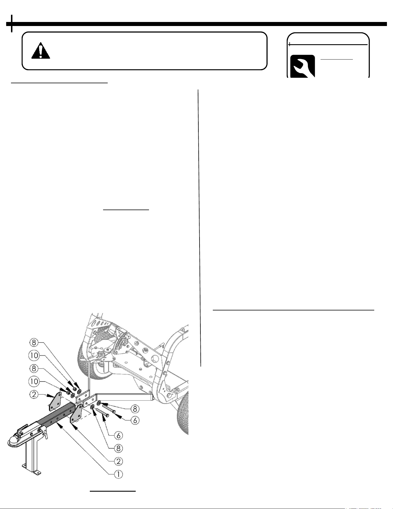
ASSEMBLY DIRECTIONS
1. Check that all parts are present before
b
eginning assembly. See page 8
2. Uncrate the Spreader using the directions
on page 9.
3. Next, locate the Hitch Coupler Bar pre-
assembly (1). Notice there are multiple
empty holes. This allows for you to locate
the spreader distance to the tow vehicle so
the control handle is reachable.
4. After deciding which mounting holes best
suits your tow vehicle, assemble the hitch
components.
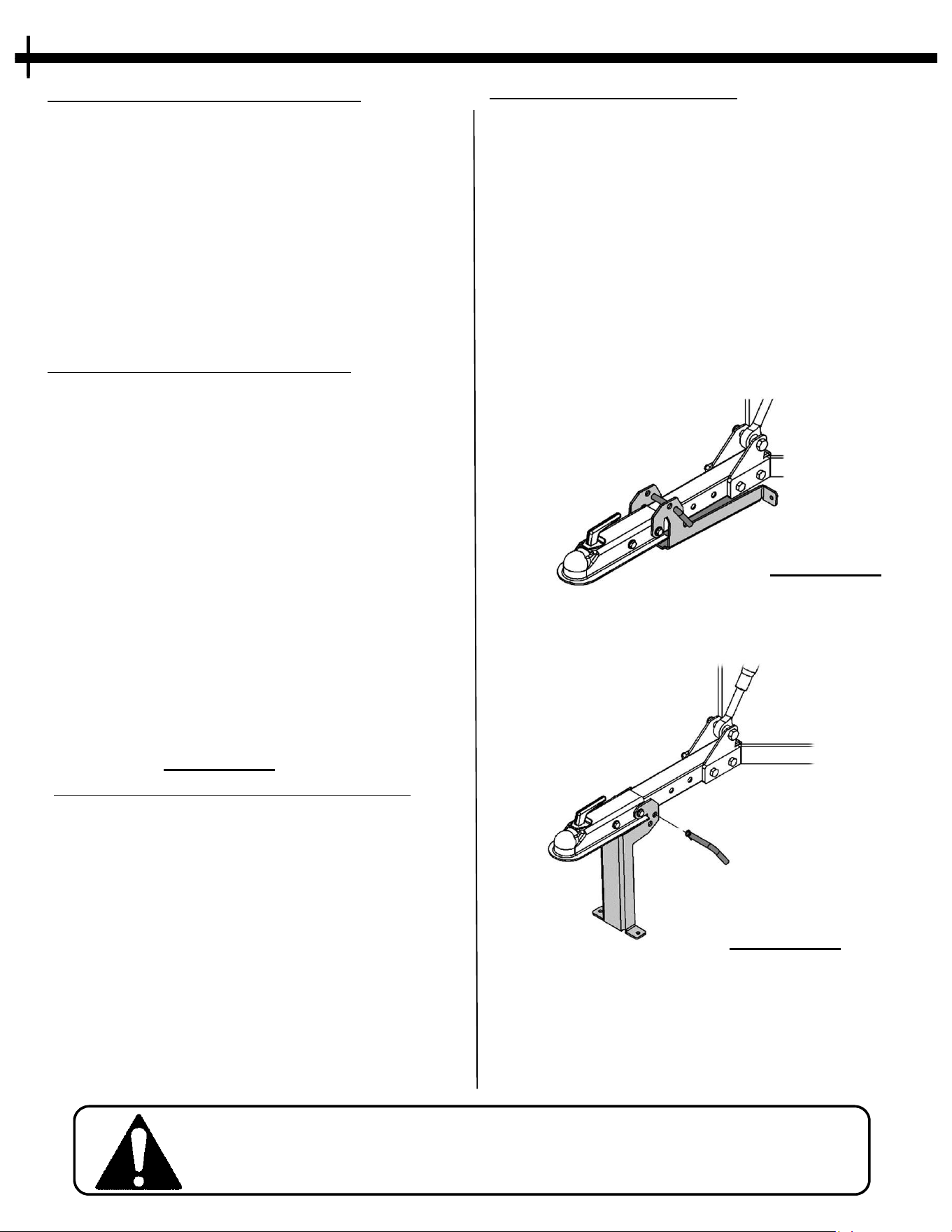
5. Place the Hitch Bar (1) in between the Top
Link Brackets (2) and Hitch arms as Shown
in FIGURE 10.2. The Plates (2) go in
between the hitch arms and the Hitch Tube.
See FIGURE 10.3 for an assembled hitch
image if needed.
10
FIGURE 10.1
ASSEMBLY DIRECTIONS
ASSEMBLY DIRECTIONS CONTINUED
6. Next using one 5/8”-11 Bolt (7) & one
5
/8”-11 Nylon Lock Nut (9), assemble
the bottom section of the top link (3)
between the top link Brackets
previously installed per Figure 10.2.
Tighten until at least one thread
protrudes from the backside of the
Nylon Nut.
7. Lastly connect the Top Link to the top of
the Spreader Frame using the
Removable ½” Pin (4) and hair pin.
8. After fully Assembled, ensure all
hardware has been tightened.
9. The Spreader is now fully assembled.
Follow the guidelines in this manual to
ensure the control linkages are
calibrated and all other hardware is
secure.
Wrench/Socket
Q
ty. Size
(2) 3/4”
(
2) 15/16”
Tools Required:
Item numbers shown are referencing the
a
ssembly parts list on PAGE 8.
FIGURE 10.3
FIGURE 10.2
11
The operation of any spreader can produce foreign objects that can be thrown into the
e
yes, resulting in severe eye damage. Always wear certified safety glasses or wide-
vision safety goggles over spectacles when standing near a spinning spreader disc.
CAUTION! Tragic accidents can occur if the operator is not alert to the
presence of children. Children are often attracted to the machine. Never
assume that children will remain where you last saw them.
BASIC SPREADER CONCEPTS
Your tow behind spreader uses the centrifugal force from a spinning disc to “spread” material.
T
he spinner disc is connected to a gearbox that is connected to an axle/tire. The tire will turn
when the unit is pulled by the tow vehicle and this will cause the disc to spin. The speed the disc
spins is determined by the speed the unit is being pulled. The material will throw farther and
provide a thinner layer of coverage as the tow speed is increased. Inversely, the spread
coverage will become thicker and shorter as the tow speed is decreased.
INTENDED USE
The Tow Spreader is designed to spread material at a designated flow rate. It is recommended to
c
alculate your flow rate before use for the most accurate application. Your Tow Spreader should
be towed behind an ATV/UTV, golf cart, lawn mower, or tractor or other similar vehicle. It is not
recommended for operating speeds exceeding 5 MPH.
MANUAL TERMINOLOGY
• Whenever “Left” or “Right” is used in this manual it refers to the left or right hand side of
t
he unit as it is in forward motion being viewed from behind.
• Refer to the “KNOW YOUR SPREADER” section for a brief overview of the spreader
components.
• “Material” refers to the product that is being spread (e.g. Grass seed, sand, salt etc…)
• FIGURE references used throughout reflect the page number as the first number( e.g.
FIGURE 20.1 is on page 20, FIGURE 15.2 is on page 15, etc…).
GETTING STARTED
Always inspect the Spreader before each use. Ensure all hardware is tight and
a
ll moving parts are in proper working order. Machine damage and/or injury
can occur if Spreader operates with defective parts.
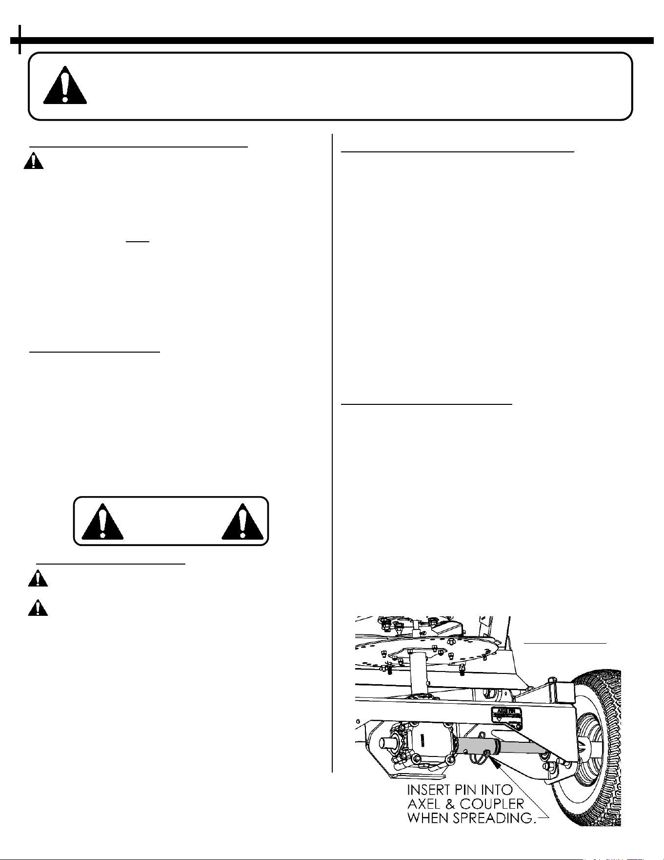
The Spreader has high speed components and throws debris a long distance.
A
lways make sure no one is within 100 feet of the spreader when in use. Stop
use if someone approaches spreader.
CAUTION! This Spreader is not intended for roadway use. It is not advised to
transport this spreader on the roadway without proper lights, signage and safety
features. Always refer to applicable laws in your area for proper roadway use.
Do not exceed 15 MPH when transporting with an empty hopper or 5 MPH with a
loaded Hopper.
ү
CONNECTING SPREADER
• Connect the Spreader to the tow vehicle while
t
he Spreader is empty.
• Remove the ½” Pin from the hitch stand. Lift
the Spreader tongue and swing the Stand
under the hitch bar so it is out of the way.
• Set the ball coupler on the 2” ball and push
the coupler lock handle down. This locks the
coupler to the ball. Insert the safety pin
(NB518) into latch handle to keep the lock
from accidentally unlatching during use.
• Swing the Stand up against the bottom of the
hitch bar. Re-insert the previously removed
½” pin into the lower hole to retain the stand
in the up position.
• Level the Spreader. See page 13 for leveling
instructions.
CAUTION: NEVER ATTEMPT TO MANUALLY MOVE, CONNECT OR
DISCONNECT A FULLY LOADED SPREADER.
12
GENERAL RECOMMENDATIONS
• It is not recommended to tow behind a car
o
r truck.
• The Tow Hitch Bar is adjustable so the
Control Handle can be reached from the tow
vehicle.
• Ensure the tow vehicle is rated to tow the
weight of the loaded Spreader.
• If the Control Handle is unreachable from
the tow vehicle, refer to page 10 for
instruction on adjusting the Hitch Bar length.
TOW VEHICLE REQUIREMENTS
• The tow vehicle must be equipped with a 2”
b
all.
• The top of the 2” ball should be no less than
11” and no more than 20” off the ground.
Anything outside of this range will require
additional equipment to raise or lower the
ball height as needed so that the Hopper
can be leveled.
FIGURE 12.1
FIGURE 12.3
SPREADER & TOW VEHICLE SET-UP
FIGURE 12.2
IMPORTANT SAFETY INFORMATION
• ALWAYS Chock the Wheels of the Spreader
s
o it cannot roll when not attached to tow
vehicle.
• Always pin the Hitch latch closed to prevent
the hitch from disconnecting unexpectedly.
• Never Fill Hopper without the spreader
being connected to a tow vehicle.
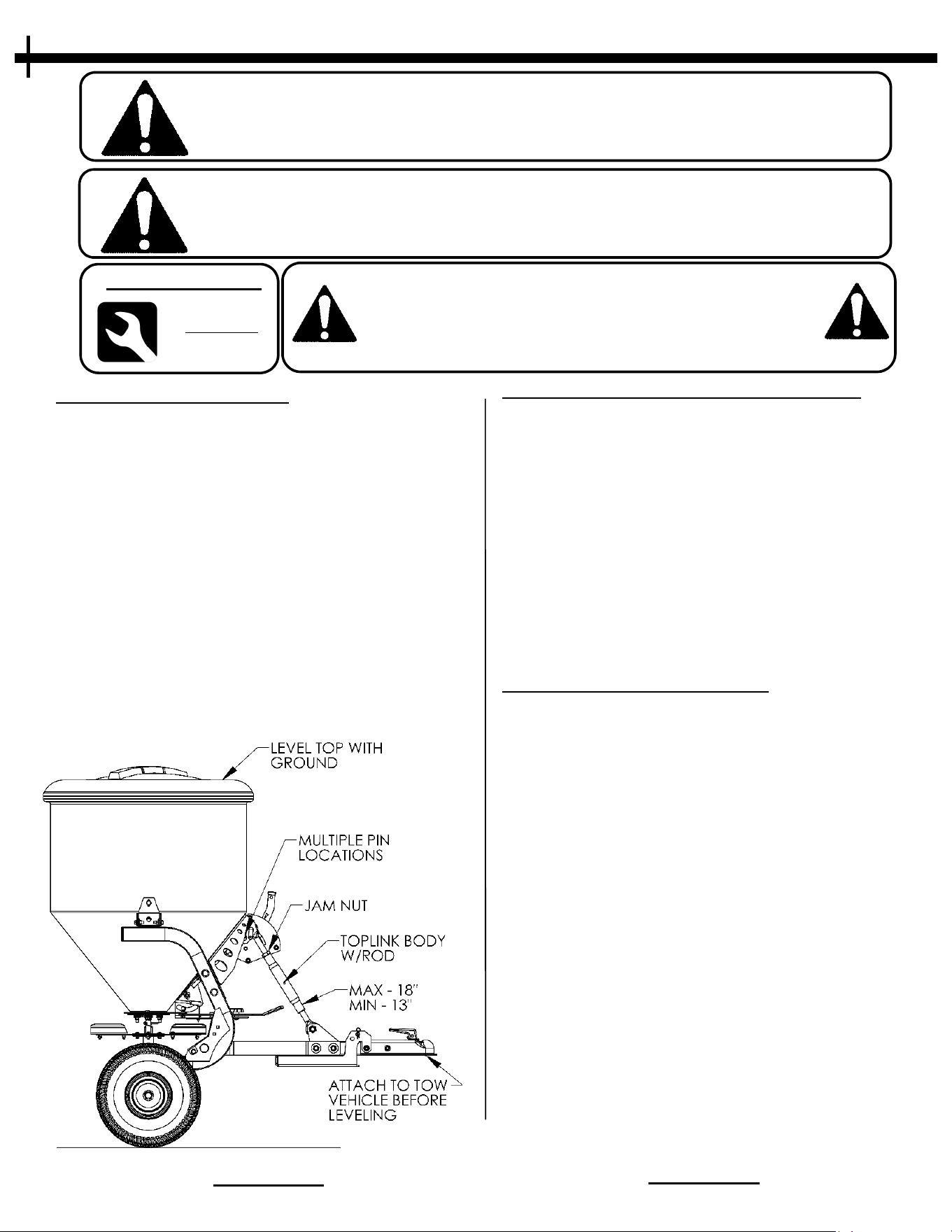
DO NOT OVEREXTEND THE TOP LINK. T
he
maximum span of the top link is 18”. If the top
link is extended beyond this, it may come apart.
WARNING:
ALWAYS LEVEL THE HOPPER WITH AN EMPTY
HOPPER! A FULLY LOADED SPREADER CAN CAUSE THE UNIT TO
BE UNSTABLE UNTIL IT IS PROPERLY LEVELED.
13
LEVELING THE HOPPER
• After the Spreader is securely attached to
t
he tow vehicle, it is necessary to level the
Spreader to the best of your ability.
• To level the Spreader, make sure the tow
vehicle and Spreader are on a relatively
level flat surface.
• Locate the Leveling top link in the front of
the unit. See FIGURE 13.1
• Using a wrench loosen the jam nut located
on the top link threads. Thread the jam nut
up the threads so it is out of the way.
• Once the jam nut is moved, determine if you
need to make the Hopper lean towards the
tow vehicle or away from the tow vehicle to
bring it to level.
Wrench
Q
ty. Size
(1) 3/4”
T
ools Required:
FIGURE 13.1
SPREADER & TOW VEHICLE SET-UP
WARNING:
ALWAYS SET THE PARKING BRAKE ON THE TOW
VEHICLE BEFORE WORKING WITH THE EQUIPMENT TO PREVENT
ACCIDENTAL MOVEMENT.
LEVELING THE HOPPER CONTINUED
• If you need to make the Hopper come
t
owards the Tow Vehicle, then you will
shorten the top link.
• If you need to make the Hopper go away
from the Tow Vehicle, then you will lengthen
the top link.
• To change the top link length, find the rod in
the center of the top link body and use it to
rotate the body. Rotating the top link body
in one direction will lengthen it and rotating
in the opposite direction will shorten it.
TRANSPORTING SPREADER
• Never transport long distances with a
l
oaded Hopper.
• When transporting the Spreader remove the
Axle Pin and place it in the Pin Storage Hole
indicated by the “AXLE PIN” Decal. Only
have pin placed in the axle when actively
Spreading. See FIGURE 13.2
FIGURE 13.2

FLOW CONTROL HANDLE
• Locate the Flow Control Handle on the operator
s
ide of the Spreader as shown on page 7.
• The Indicator Dial has marked intervals to
represent the amount of material that is
dropped while spreading. See page 30 for
information on how to calculate the flow rates
for your desired medium.
• The Control Assembly has two indicator arrows
for the operator to select the desired flow rate.
The red arrow indicates a pre-set open setting.
The arrow on the Handle indicates the current
opener location.
FLOW CONTROL HANDLE OPERATION
• The Red Arrow indicates a pre-set value. This
p
osition is selected by loosening the Black
Knob and moving the Indicator to the desired
setting.
• Once the Indicator Arrow is pointing to the
desired setting, tighten the Black Adjustment
Knob to lock handle stop in place. The Control
Handle will not be able to move past the pre-
set value.
14
FIGURE 14.1
CONTROL OPERATIONS
FIGURE 14.2
OFFSET ADJUSTMENT HANDLE
• Locate the Offset Control Handle located on the
F
rame cross member as shown on page 7.
• The Offset Control Handle has an indicator
plate that reflects the direction the material will
be spread.
• When the Handle is set to the dot below the “R”
material will Spread a 90° Fan the “Right” side
as the unit is in operation.
• When the Handle is set to the dot below the “C”
material will Spread a Full 180° Fan pattern.
• When the Handle is set to the dot below the “L”
material will Spread a 90° Fan the “Left” side as
the unit is in operation.
OFFSET ADJUSTMENT HANDLE OPERATION
• Slightly loosen the Offset Locking Knob by
t
urning Counterclockwise. The knob only need
to be loosened enough to allow the Offset
Control Handle to move.
• Once the Knob is loosened, move the handle to
the desired spread direction as described
above. Retighten the Knob.
• The point located inside the handle viewing
cutout indicates the position of the Offset Plate.
FIGURE 14.4
FIGURE 14.3
OFFSET ADJUSTMENT HANDLE
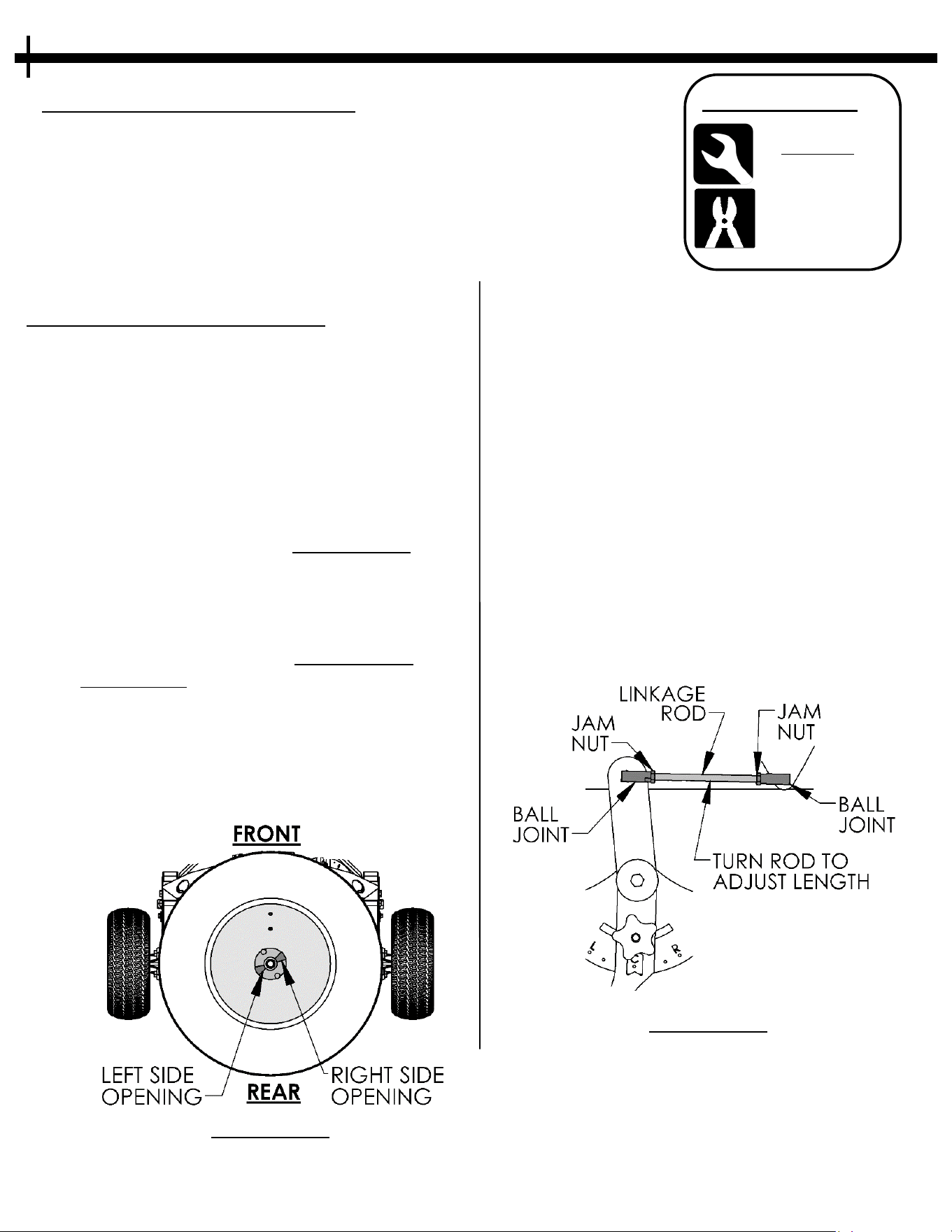
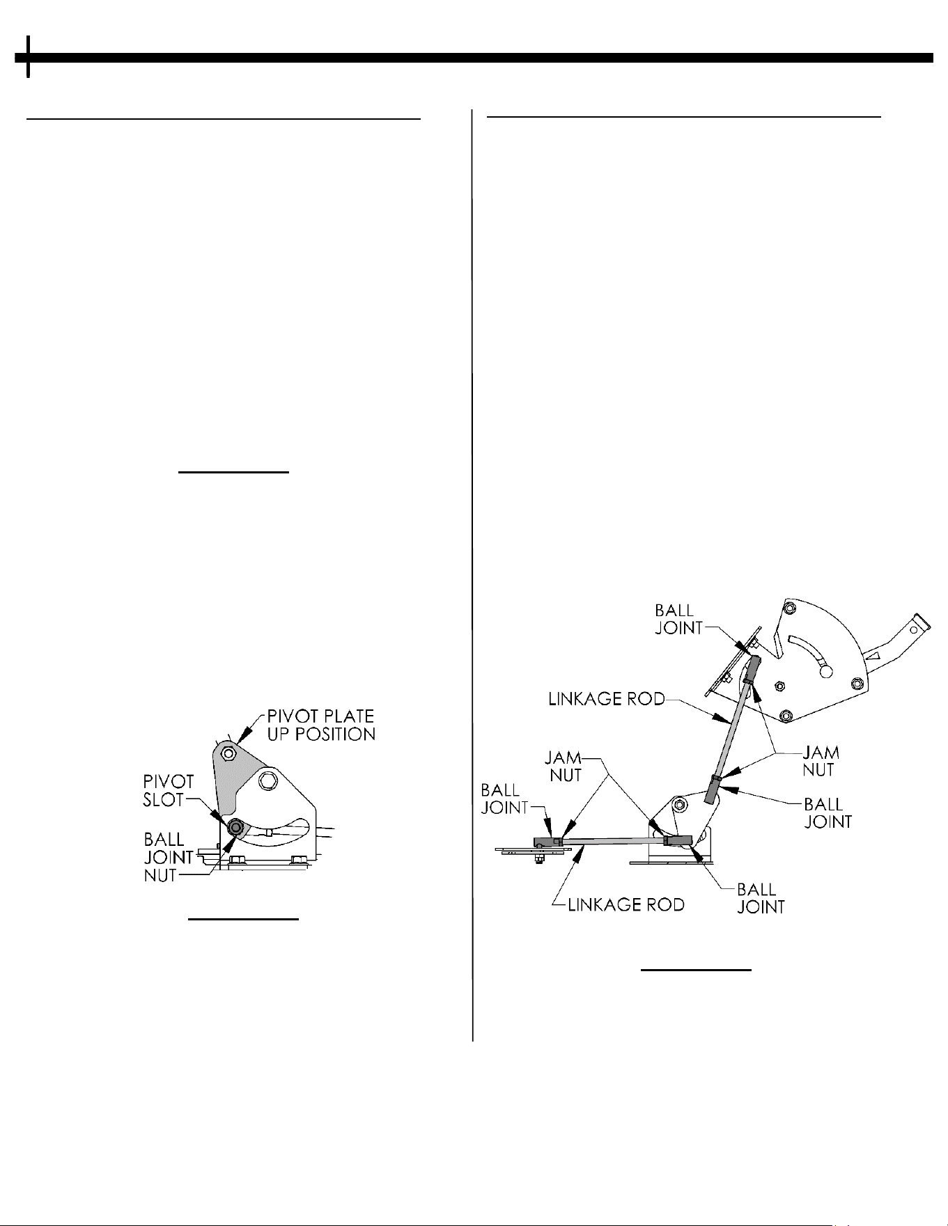
1) To Calibrate the Offset
C
ontrol Handle, place
the handle to “C” Center
position and lock in
place as shown in
FIGURE 15.1
2) Set the Flow Control
Handle to Setting “4”
(Fully Opened).
3) When standing at the rear of the Spreader
looking into the Hopper, see which hole is
not fully Open. If both holes are not fully
opened then follow the “Flow Control
Calibration” S
teps on page16. If only one
hole is partially covered, take note as to
w
hether it is the right hole or the left hole. If
both holes are fully open, no adjustment is
needed.
15
FIGURE 15.2
Opening Holes
CONTROL CALIBRATION
4) Go back to the Offset Control Handle and
l
ocate the Linkage rod as shown in
FIGURE 15.3.
5) Using a 7/16”& 1/2” open end wrench,
loosen the jam nuts at both ends of the rod.
One nut is left-hand thread and one is
right-hand thread.
6) Once the jam nuts are loose and moved
away from the ball joint, turn the rod to
lengthen or shorten the linkage. If the left
hole was covered then shorten the linkage.
If the right hole was covered then lengthen
the linkage. Adjust rod as necessary until
both holes are fully opened.
7) Once both holes are fully opened re-
tighten the jam nuts.
GENERAL RECOMMENDATIONS
• Calibrate the controls with an empty hopper.
•
It is easier to have two people when calibrating the control
linkages. One person to watch the slide plates and the other person
operating the controls and making the necessary adjustments.
• It is recommended to calibrate the controls often to ensure proper
functionality of the slide plates.
Wrench
Q
ty. Size
(2) 1/2”
(
1) 7/16”
Tools Required:
Pliers
(
Optional)
FIGURE 15.3
Offset Control Handle Linkage
FIGURE 15.1
FLOW CONTROL HANDLE CALIBRATION
1) To calibrate the Flow Control Handle, place
t
he handle to the Zero (0) Setting. Loosen the
Flow Control Handle Adjustment Knob and
position it at the Zero (0) Location also. This
will lock the Control in the fully closed
position.
2) Next, look inside the Hopper at the slide
plates. The opening holes should be fully
closed. If they are fully closed, skip to step
10. If not continue on to step 3.
3) With the handle still locked in the closed
position, locate the Control Handle linkage
rod connection Pivot Plate.
4) The Pivot Plate should be in the up position
and the Ball Joint Nut should be nearly
bottomed out in the slot as shown in FIGURE
16.2.
5) If the Nut is not bottomed out in the slot then
find the Control Handle Linkage Rod.
6) Using a 7/16” wrench and ½” wrench,
loosen the jam nuts on the rod. One of the
nuts is right hand threaded and the other is
left hand threaded.
16
CONTROL CALIBRATION
FLOW CONTROL HANDLE CALIBRATION
6) After the nuts are loosened turn the linkage
r
od to lengthen or shorten the rod as needed
to bring the plate into the correct position as
shown in FIGURE 16.3. Re-tighten the jam
nuts on the linkage rod.
7) Look inside the Hopper to see if this
adjustment has fully closed the Holes at the
bottom. If so skip to step 10. If not continue
to step 7
8) Locate the linkage rod connecting the pivot
bracket to the slide plate on the Hopper.
Follow steps 5 & 6 on this linkage rod to
moved the Slide plate into the fully closed
position.
9) After the rods have been adjusted, verify
they are correct by loosening the Flow
Control Adjustment Knob and moving the
Handle to Setting (4) fully open. Look inside
the Hopper and verify the Holes are Fully
Opened.
FIGURE 16.1
FIGURE 16.2
FIGURE 16.3
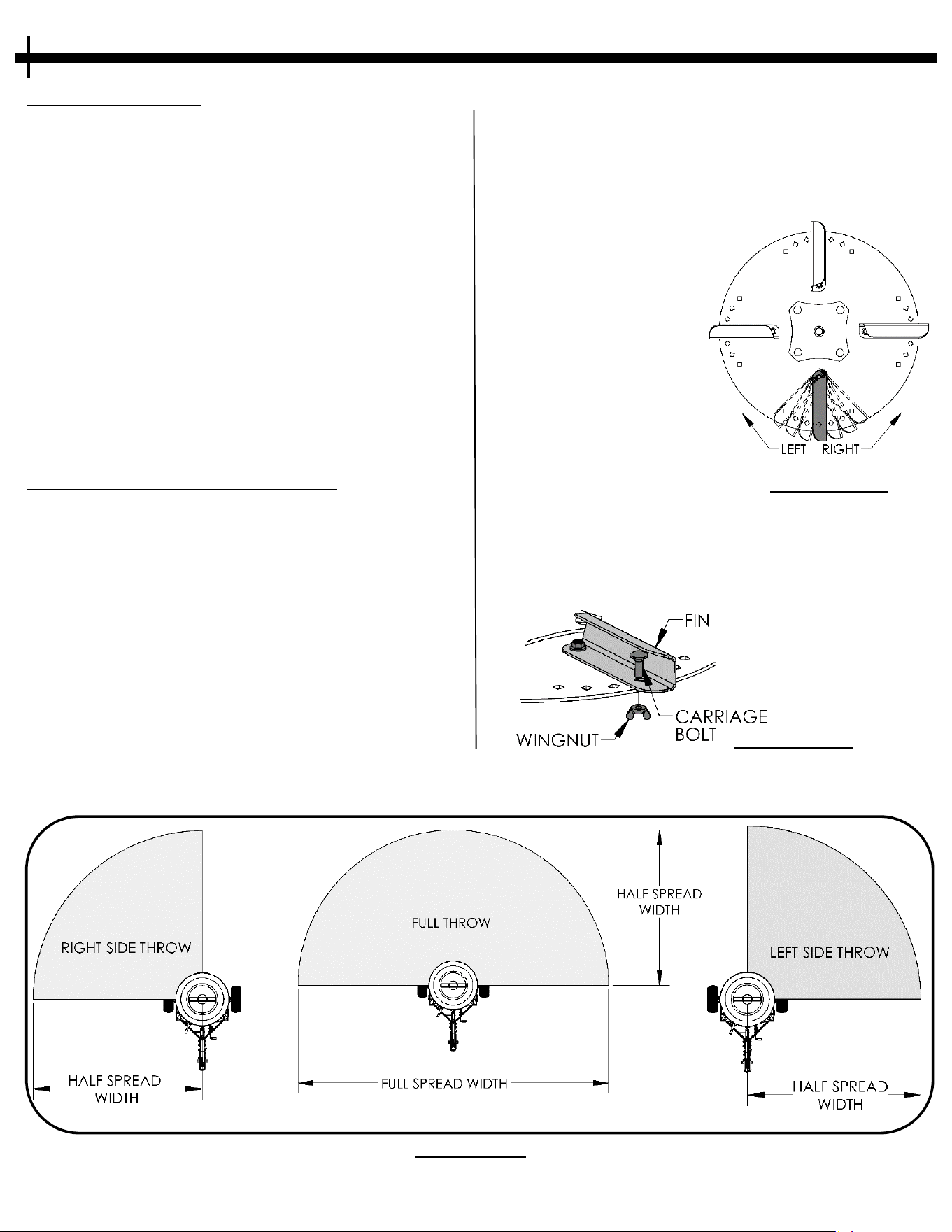
• The adjustment Fins will let you fine tune the
s
pread pattern. Move the fins in the direction
that you want more material to be applied.(e.g.
If the material is spreading to heavy to the left
then move the Fins to the right for the spread to
become heavy on the right. See FIGURE 17.1.
• Note: When you move
fins to the left this will
lessen the distance the
material is thrown.
When the fins are set
towards the Right this
will increase the
distance the material
is thrown.
• To adjust the fins, remove the wing nut and
carriage bolt that connected the Fin to the
Spinner Disc. The Fin should now be free to
pivot around the rear bolt.
• Adjust the Fin in the desired direction and
replace the carriage bolt and wingnut.
17
FIGURE 17.3
Spread Patterns
SPREAD PATTERN ADJUSTMENT
SPREAD PATTERN
• By positioning the Offset Adjustment Handle
d
etailed on page 14, you can set the spread
pattern. See Spread Patterns in FIGURE 17.3
• Note: Due to the nature of using rotational
force to “throw” the material it is impossible
to completely eliminate material from
throwing in a certain direction. The use of
the Offset Handle will drastically reduce the
amount of material dispersed to one side.
• It’s recommended to do a couple test passes
with the desired material to see how it will react
when being dispersed. If needed you can fine
tune the spread pattern by gradually adjusting
the Offset Control Handle or using the
adjustable fin on the spinner disc.
FINE TUNING SPREAD PATTERN
• If you notice the spread pattern becomes
h
eavier or uneven to one side utilize the Offset
Handle to limit material flow to the heavy side.
• For example, if the material is flowing heavier
to the right side then move the Offset
Adjustment Handle slightly towards the “L”
Left. This will reduce material flow to right side
of the unit. The farther the handle is moved
away from “C” the more the flow is restricted.
FIGURE 17.1
FIGURE 17.2
㜐
Ұ
18
GENERAL OPERATIONS
GENERAL RECOMMENDATIONS
• Learn and refer to all safety warning in this
m
anual before operating the Spreader.
• If Spreader is being on or near a roadway
always follow local laws and regulations for
road transporting in your area. The
Spreader is not designed for high-speed
roadway use! Do not exceed 15 MPH when
t
ransporting an empty unit with the axle
pin removed. Do not exceed 5 MPH with
the axle pin in place and/or a loader
Hopper.
GETTING STARTED
• Is it important to learn all the operations
d
iscussed in this manual before starting.
• Decide whether or not the Agitator Head is to
be used before filling the Hopper. The
Agitator can cause damage to some coated
and/or delicate seeds. Calculate the flow
rate of the material to be spread for the
most accurate results.
• Ensure the flow gate is closed prior to filling.
Always inspect the Spreader before each use. Ensure all hardware is tight and all
m
oving parts are in proper working order. Machine damage and/or injury can occur
if Spreader operates with defective parts.
Always inspect the Spreader before each use. Ensure all hardware is tight and all
m
oving parts are in proper working order. Machine damage and/or injury can occur
if Spreader operates with defective parts.
Always inspect the Spreader before each use. Ensure all hardware is tight and all
m
oving parts are in proper working order. Machine damage and/or injury can occur
if Spreader operates with defective parts.
FILLING THE HOPPER
• M
ake sure the Spreader is securely
connected to the Tow-Vehicle.
• Always fill the hopper at the site where
the material is to be spread. Traveling
with a full Hopper will cause the material
to compact and can result in poor
spreading.
• The recommended method of filling the
Spreader is to place the unopened bag of
material on the top ledge of the Hopper.
Place the end of the bag to be opened into
the opening of the Hopper. Open the bag
and let the material fall into the hopper by
lifting the opposite end of the bag. Repeat
this step until the desired amount of material
is in the Hopper and then replace the
Hopper Lid.
SPREADING RECOMMENDATIONS
• When spreading the first pass, take note of the
s
pread width and distribution pattern.
• Pay close attention to your speed, as this will
directly impact the spread width and material
coverage area. The faster you go, the wider
and thinner the coverage will become. The
slower you go, the thicker and narrower the
coverage area will become. It is important to
maintain a consistent speed for even
coverage.
• If the pattern seems to be uneven or applies
material heavier in one direction then follow
the instructions for FINE TUNING THE SPREAD
PATTERN on page 17.
STARTING SPINNER DISC
• E
nsure the axle locking pin is in place. SEE
FIGURE 18.1 Once the Drive axle is attached
to the Gearbox, the Spinner Disc will spin
upon forward or backwards movement of the
spreader.
• Ensure the Hopper is level.
• Set the Pre-set Knob to the desired Open
setting on the Flow Control Handle.
• Set the desired material spread offset (Left,
Right or Center).
• You are ready to spread!
• Follow the pattern in FIGURE 19.1 for best
results.
FIGURE 18.1
600 L
B
CAPACITY

歰
ҙ
19
GENERAL OPERATIONS
SPREADING IN FIELD
• There are many effective ways to use the spreader. The following guideline is a suggested way to
e
nsure even coverage.
• For best results, it is recommended to set the flow rate at half of the desired coverage and cover
the area twice. The second coverage route should be perpendicular to the first coverage route.
This is the best method to achieve even coverage with lower chances of thin or missed spots.
GENERAL OPERATIONS
SPREAD ZONE COVERAGE
See FIGURE 19.1
1
. Position the Spreader in the corner
of the area to be covered as
indicated by the “START POINT” at
half the spread width from both
edges of the spread area.
2. Open gates to the desired flow rate
setting and begin moving forward at
the required speed along route “A”.
Route “A” will continue around the
perimeter at a Half Spread Width
distance from the edge of area.
3. Once you are a distance of SW/2
from the “Start Point”, turn to
continue along route “B”. Route “B”
and route “A” should be a Spread
Width apart. Make sure to not leave
a gap between route “A” and “B”.
4. When you reach route “A” close the
gate and turn the unit to go in the
opposite direction alone route “C”.
5. Once you are aligned with route “C”
and are a distant of one spread
width from the edge, reopen the
gate and travel straight along Route
“C”. Again, ensure there is no gap
between route “B” & “C”
6. Repeat Steps 4 & 5 until you have
covered the entire area.
“SW” = Spread Width
“SW/2” = Half Spread Width
FIGURE 20.1
BEFORE YOU START
• I
t is strongly recommended to calculate the spread pattern and flow rates of the
material you will be spreading. If you do not do this, the spreader may not
produce desired results. See page 30-32 for flow rate calculation procedures.
CAUTION: CARELESS OR IMPROPER HANDLING MAY RESULT IN
SERIOUS INJURY.
20
GENERAL RECOMMENDATIONS
The warranty on this Spreader does n
ot cover items that have been subjected to operator abuse or
negligence. To receive full value from the warranty, operator must maintain unit as instructed in
this manual.
Some adjustments will need to be made periodically to maintain your unit properly.
BEFORE EACH SEASON
• Check the UHMW Washer (21967) for wear, replace if needed. See P
age 31
• Check for Gearbox oil leaks.
• If a leak is found, remove Gearbox from the spreader and check oil levels.
Replace/add if oil is low or dirty. There should be 12oz of SAE 90 or 80W90 gear oil in
the gearbox.
• Check Wheel Bearings for failure or damage.
• Check Operation of All Controls.
• Check tires for wear and damage.
• Replace Agitator Cotter Pin (10936). See Page 31
BEFORE EACH USE
• Check all Hardware for Looseness or Damage.
•
Check Tires for proper inflation.
• Ensure axle Pin is either in the holding location or the Axle Coupler.
• Lubricate threads of Top Link (P/N 21103) if needed.
AFTER EACH USE
• Check all Hardware for Looseness or Damage.
•
Check Tires for proper inflation.
• Clean Thoroughly. Refer to page 21 for cleaning guide.
Important: Replace parts that have been damaged.
Important: Check Disc and Hopper mounting hardware on a regular basis to make sure it is
tight.
SPREADER MAINTENANCE
楰
ҟ
GENERAL RECOMMENDATIONS
• Always thoroughly clean the spreader after
e
very use.
• Use fresh clean water to clean.
• Allow to completely dry before using after
cleaning.
21
CLEANING GUIDELINES
CLEANING THE HOPPER
• Empty all bulk material left in the Hopper.
•
Remove the Removable Pin from the top link
located next the Flow Control Handle . This will
Allow the Hopper to lower and become easier
to access for cleaning. See FIGURE 22.1 & 22.2
• Using clean water and a rag. Thoroughly clean
the inside of the Hopper and all Components. It
may be necessary to remove the agitator to
clean particles that may be trapped
underneath.
• Also thoroughly clean the slide plates, spinner
disc, and gearbox.
• Check the internal plastic sealing washer (Part
# 21967) for damage and clean all debris that
may have gotten under the washer. See page 31
for washer detail.
• Once the Hopper is clean, if cleaned with water,
make sure it is completely dry before adding
material. Wet material can result in poor
function and corrosion.
FIGURE 22.1
FIGURE 22.2
WARNING:
PROPER CLEANING IS ONE OF THE MOST
IMPORTANT STEPS IN CARING FOR YOUR SPREADER. SOME
MATERIALS CAN BE HIGHLY CORROSIVE AND WILL CAUSE
DAMAGE TO SPREADER COMPONENTS IF NOT CLEANED !
IF PROBLEMS PERSIST HAVE A QUALIFIED MECHANIC SERVICE
T
HE SPREADER. NEVER ATTEMPT TO MAKE AN ADJUSTMENT
THAT YOU ARE NOT SURE IS CORRECT. DOING SO CAN CAUSE
OTHER PROBLEMS.
22
TROUBLESHOOTING
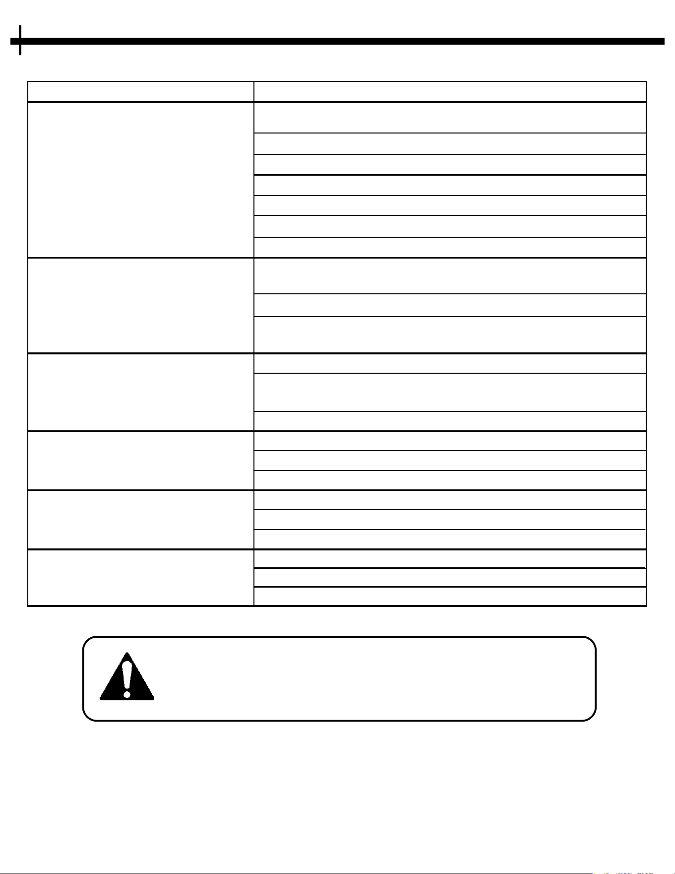
ISSUE SOLUTION
Check that the Axle Engagement Pin is in Place.
Check Axle or Coupler for possible Damage.
Ensure Key is in the Wheel
Check Gear Box For Damage.
Ensure Key and Set screw are in place on Axle Coupler
Ensure Key and Set Screw are in place on the Disc Coupler
Ensure the Spreading Disc is level with the ground by adjusting
the top link.
Check Tire pressure and for tire/wheel damage.
Check that the Control Handle is Open to the desired Flow Level.
Check Linkages between slide plates and Control Handle.
Check for Opening Slot Blockages.
Ensure Slide Plates move when operating the Control Handles.
Check for Material Jamming the internal Agitator.
Check for Damage Axle Bearings
Make sure all Moving Parts are Free of Debris.
Check that the Cotter Pin is in place and not damaged.
Check for that the Axle Pin is place.
Ensure Agitator shaft is not damaged or broken.
Check Linkage Rods and Ball Joints.
Check slide plates for damage/blockages.
Check Handle for damage.
Disc Will Not Spin
The Unit is Not Spreading Level
Material Will Not Flow
Drive Tire Will Not Spin
Agitator Will Not Spin
Handle Will Not Move
楰
ҟ
23
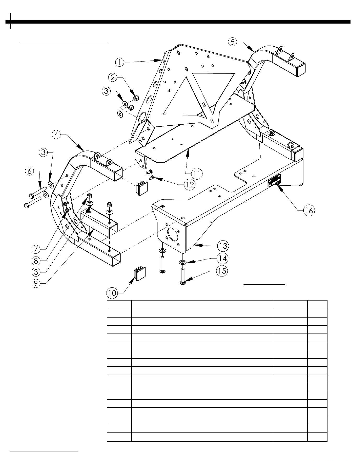
When ordering replacement parts
* = USE PAINT CODE: TK=BLACK
FIGURE 25.1
FRAME ASSEMBLY
Note: S
ome parts not shown for clarity.
PARTS DIAGRAMS
PARTS DIAGRAMS
ITEM #
DESCRIPTION PART # QTY
1 WELDMENT - HOPPER SUPPORT 21959* 1
2 NUT- 1/2-13 NYLON LOCK NB281 4
3 WASHER - 1/2 USS FLAT 18823 12
4 WELDMENT - FRAME ARM, LEFT 21941* 1
5 WELDMENT - FRAME ARM, RIGHT 21983* 1
6 BOLT - 1/2-13 X 3 1/4 12669 4
7 NUT - 5/16-18 SERR FLANGE NB170 4
8 NUT - 1/2-13, 2-WAY LOCK 12165 4
9 BRACKET - FRAME, 2" SQ TUBE CLAMP 21938* 2
10 PLUG, FINISHING - 1 X 3 X .083 TUBE 50062009 4
11 WELDMENT - CONTROL SUPPORT 21962* 1
12 BOLT - CARRIAGE, 5/16-18 X 3/4 10216 4
13 WELDMENT - SPREADER BASE FRAME 21943* 1
14 WASHER - 3/4 ID X 1 1/4 OD 18 GA NB179 4
15 BOLT - CARRIAGE, 1/2 X 3" 10500 4
16 DECAL - AXLE PIN 21914 1
When ordering replacement parts
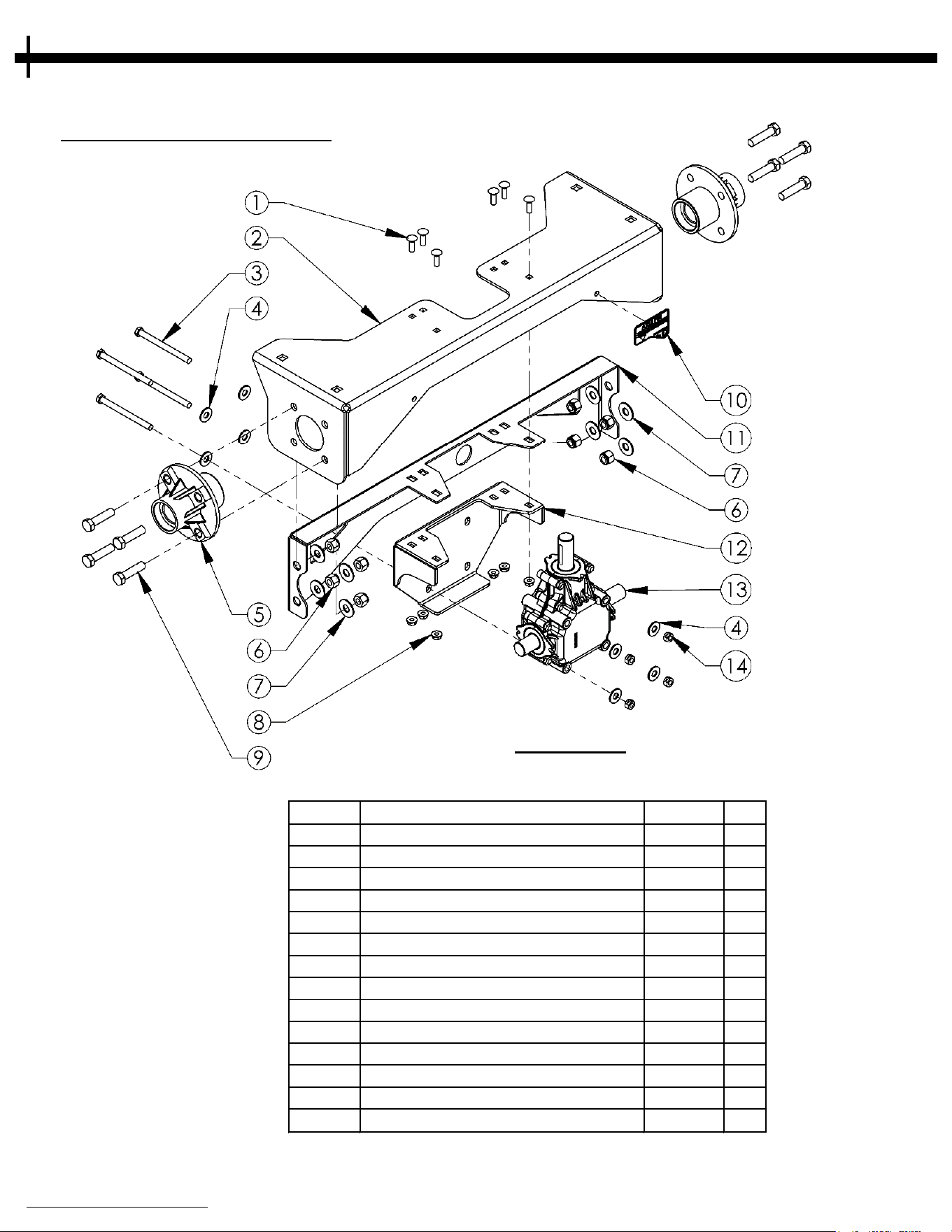
* = USE PAINT CODE: TK=BLACK
ITEM # DESCRIPTION PART # QTY
1 BOLT - CARRIAGE, 5/16"-18x1" 10197
6
2 WELDMENT - BASE FRAME 21943*
1
3 BOLT - HEX, 3/8"-16x4 1/2" NB674
4
4 WASHER - FLAT 3/8" NB271
8
5 BEARING HOUSING - CAST 4858*
2
6 NUT - NYLON LOCK, 1/2"-13 NB281
8
7 WASHER - FLAT, 1/2" NB555
9
8 NUT - SERR FLANGE, 5/16"-18 NB170
6
9 BOLT - HEX, 1/2"-13x2" NB509
8
10 DECAL - AXLE PIN 2
1914
1
11 WELDMENT - BASE SUPPORT 21984*
1
12 WELDMENT - GEARBOX MOUNT 21944*
1
13 GEARBOX 21394
1
14 NUT - 2-WAY LOCK, 3/8-16 NB280
4
GEARBOX ASSEMBLY
FIGURE 26.1
24
Note: Some parts not shown for clarity.
PARTS DIAGRAMS
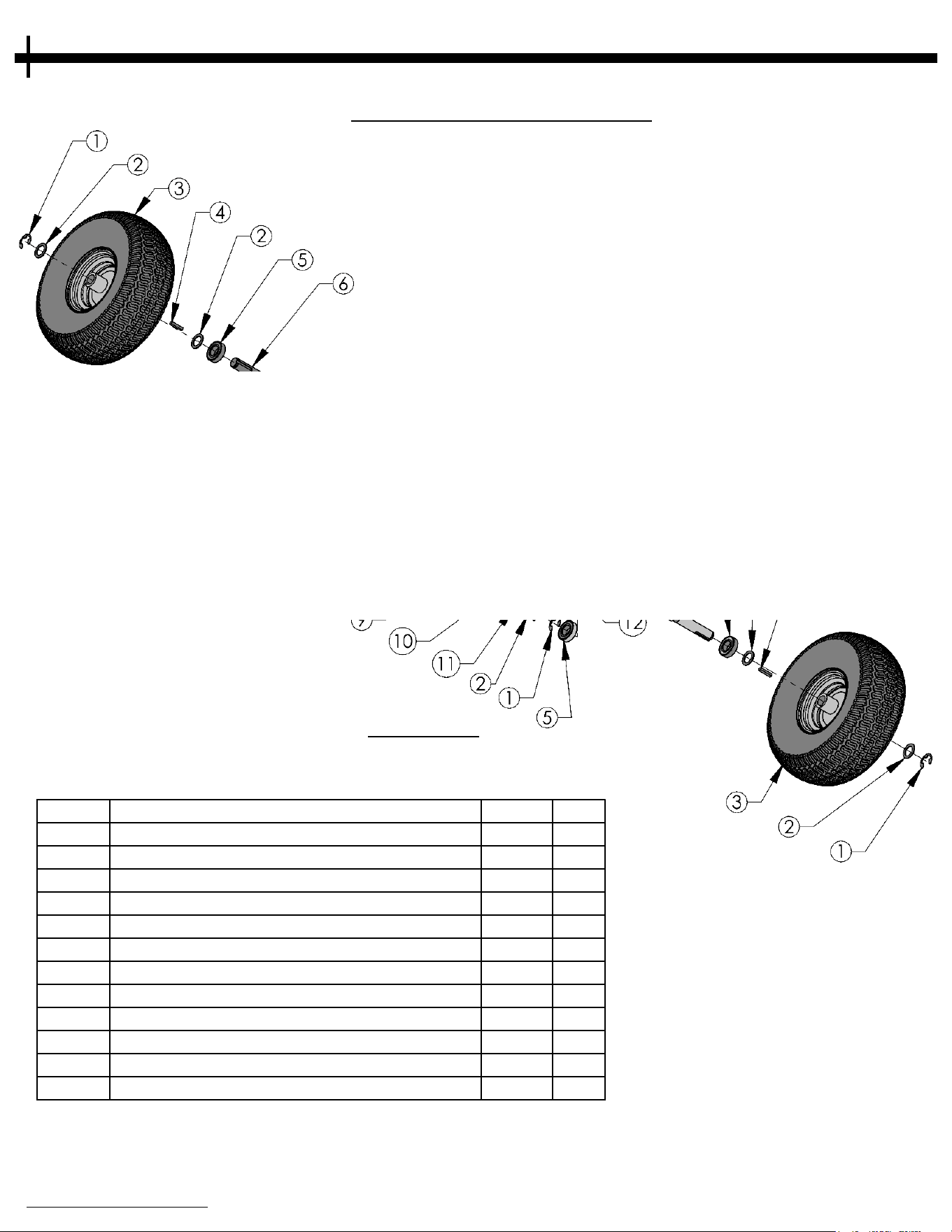
25
ITEM #
DESCRIPTION
PART #
QTY.
1 E-STYLE RETAINING RING, 1" SHAFT 10915 5
2 WASHER - 1" X 1 1/2" X 14 GA 10914 5
3 TIRE/WHEEL - 15X6.00-6 , 4 PLY, BLK 21934 2
4 KEYSTOCK - 1/4" X 1 1/2" 2437 2
5 BLADE BEARING, Ø1ID X Ø2OD 4845 4
6 SHAFT - AXLE, 1" OD, 8 15/16" LNG 21968Z 1
7 SHAFT - DRIVE AXLE, 1" OD 21953Z 1
8 KEY - 8MM X 25MM LONG 21991 1
9 SCREW - SET 5/16-18 X 1/2 W/ LOCTITE NB312 2
10 COUPLER - GEARBOX SHAFT ADAPTOR 21956Z 1
11 BEARING - FLANGE SLEEVE, 1"ID X 1.25"OD 22001 1
12 PIN - 5/16" OD LOCKING 21986 1
FIGURE 27.1
When ordering replacement parts
* = USE PAINT CODE: TK=BLACK
Note: Some parts not shown for clarity.
PARTS DIAGRAMS
TIRE & AXLE ASSEMBLY
26
When ordering replacement parts
* = USE PAINT CODE: TK=BLACK
Note: Some parts not shown for clarity.
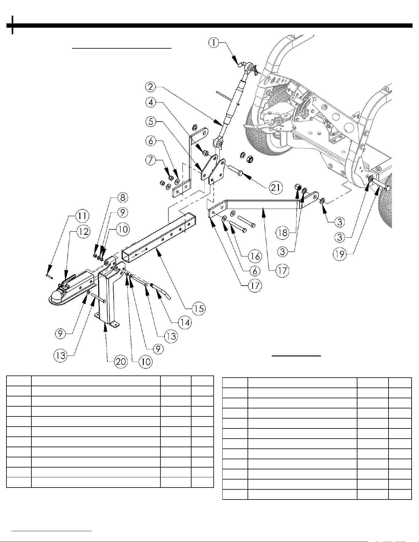
FIGURE 28.1
ITEM
DESCRIPTION
PART #
QTY.
1 PIN - 5/8" X 3" W/ HAIRCLIP NB702 1
2 TOP LINK 21103 1
3 WASHER - 3/4"ID X 1 1/4"OD NB184 6
4 NUT - 5/8"-11 NYLON LOCK 21138 1
5 PLATE - TOP LINK HITCH BRACKET 21950* 2
6 WASHER - 1/2" USS FLAT NB555 24
7 NUT - 1/2"-13 NYLON LOCK NB281 14
8 NUT - 3/8"-16 NYLON LOCK NB182 2
9 WASHER - 3/8" WASHER NB272 4
10 BUSHING 7840Z 2
HITCH ASSEMBLY
PARTS DIAGRAMS
ITEM
DESCRIPTION
PART #
QTY.
11 PIN - 1/4" X 1 1/2" CLEVIS NB518 1
12 COUPLER - 2" BALL 7365 1
13 BOLT - HEX, 3/8-16 X 3 1/2 NB649 2
14 PIN - 1/2" X 3" W/HAIR CLIP NB606 1
15 TUBE - SPREADER HITCH BAR 21946* 1
16 BOLT - 1/2"-13 X 4" HCC NB132 2
17 PLATE - HITCH ARM 21951* 2
18 NUT - 3/4"-10 NYLON LOCK NB313 1
19 BOLT - 3/4"-10 X 3 3/4" 21129 2
20 HITCH STAND - BLACK 21954* 1
21 BOLT - 5/8-11 X 3" NB699 1
27
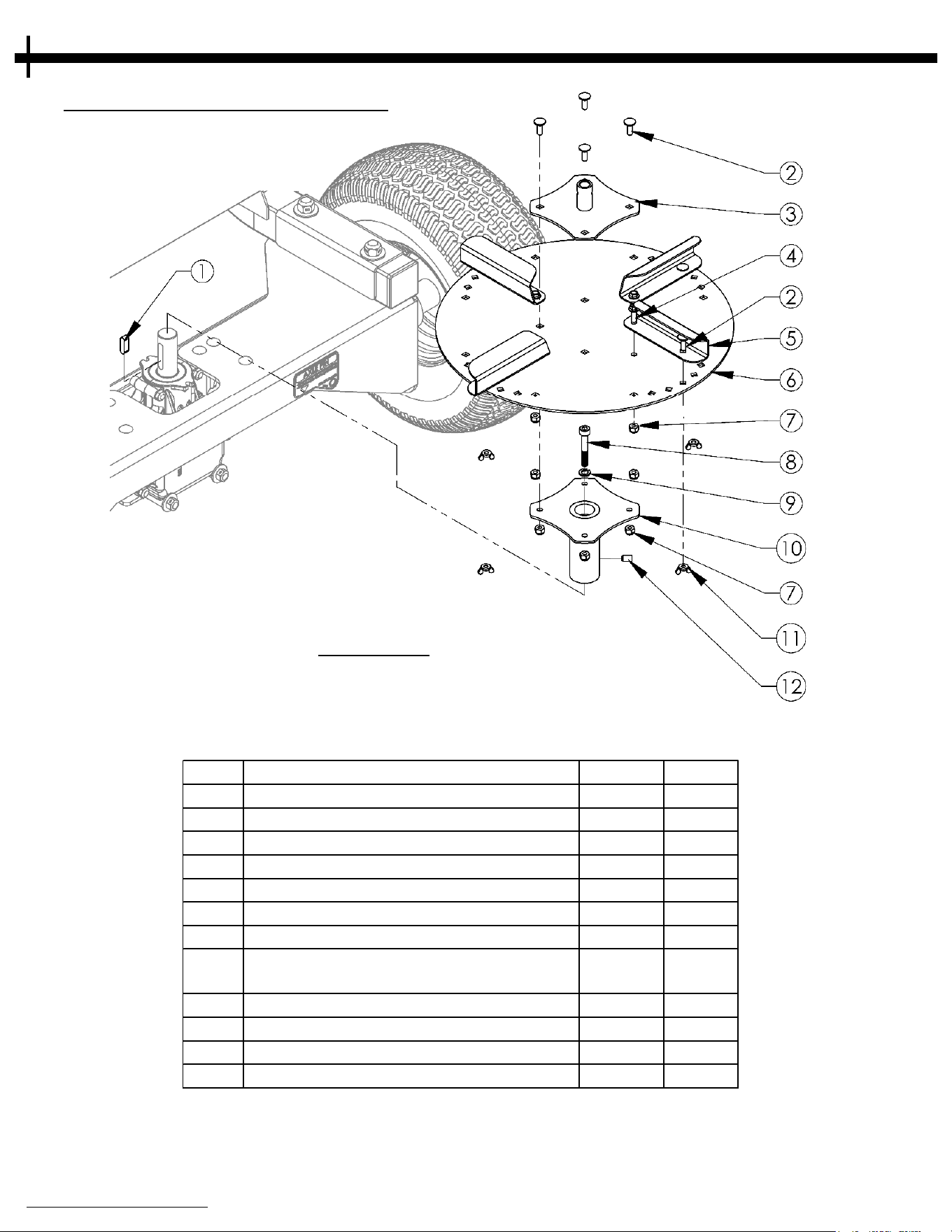
SPINNER DISC ASSEMBLY
ITEM
DESCRIPTION
PART #
QTY.
1 KEY - 8mm x 25mm LONG, ROUNDED 21991 1
2 BOLT - 1/4 - 20 x 3/4 , CARRIAGE 10547 8
3 WELDMENT - AGITATOR SHAFT MOUNT 21975GV 1
4 BOLT - 1/4-20 X 3/4, SERR FLANGE NB690 4
5 PLATE - SPINNER ARM 21939GV 4
6 PLATE - SPINNER DISC 21948GV 1
7 NUT - 1/4-20, NYLON LOCK NB180 8
8
SCREW- SOCKET HEAD,
M8X1.25X50MM
21993 1
9 WASHER - SPLIT LOCK 5/16 NB159 7
10 WELDMENT - SPINNER DISC 21947* 1
11 NUT - WING , 1/4-20 NB608 4
12 SET SCREW - 5/16-18, LOCTITE NB312 1
When ordering replacement parts
* = USE PAINT CODE: TK=BLACK
Note: Some parts not shown for clarity.
FIGURE 29.1
PARTS DIAGRAMS
28
ITEM
DESCRIPTION
PART #
QTY
1 BUSHING 6037 1
2 WASHER - 5/16" SAE NB275 1
3 BALL JOINT - RHT, 5/16-24 NB263 1
4 NUT - JAM, 5/16"-24 ZY NB190 3
5 LINKAGE - 5/16-24 LHT & RHT, 6.5" 20753 1
6 NUT - JAM, 5/16"-24 ZY, LHT NB265 1
7 BALL JOINT - LHT, 5/16-24 NB264 1
8 NUT - 3/8-16 , SERR FLANGE NB779 1
9 BOLT - 5/16-18 X 1 1/4", CARRIAGE 10217 1
10 BUSHING - 1/2" OD 7825Z 1
11 WASHER - 5/16" , SPLIT LOCK NB159 1
12 GRIP - HANDLE, ORANGE 19911 1
13 BOLT - 3/8-16 X 1 1/4", HEX NB618 1
14 WASHER - BUSHING, 3/8" ID ZP 6040Z 1
15 KNOB - PLASTIC, BLACK 2030 1
16 HANDLE - L/R/C OFFSET 21970* 1
17 WASHER - 1/2" 14 GA ZP NB177 1
OFFSET GATE CONTROL
FIGURE 30.1
When ordering replacement parts
* = USE PAINT CODE: TK=BLACK
Note: Some parts not shown for clarity.
PARTS DIAGRAMS
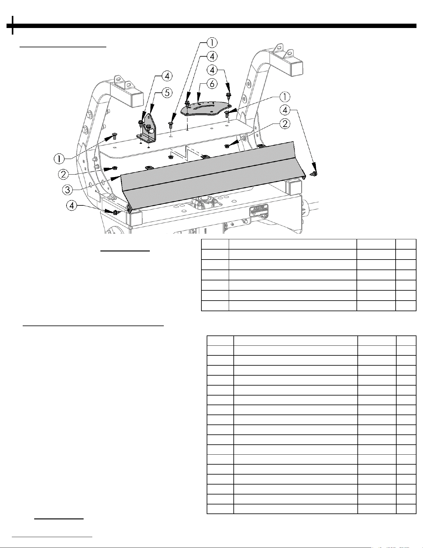
FIGURE 30.2
ITEM
DESCRIPTION
PART #
QTY
1 BOLT - CARRIAGE, 5/16-18 x 3/4" 10216 3
2 NUT - 5/16-18, SERR FLANGE NB170 3
3 GUARD - DEBRIS SHEILD 21987* 1
4 SCREW - 5/16-18 X .3/4, BLACK 26X249 6
5 BRACKET - OPEN PIVOT 21979* 1
6 PLATE - OFFSET HANDLE BASE 21971* 1
DEBRIS GUARD
Note: S
ome parts not shown for clarity.
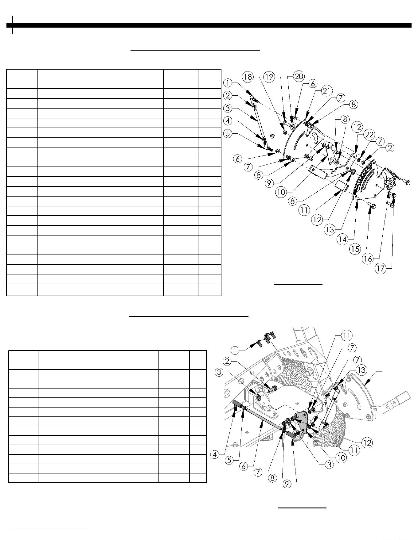
29
ITEM # DESCRIPTION PART # QTY
1
BOLT - 5/16-18 X 3/4, CARRIAGE
10216 4
2 BOLT - 5/16-18 X 1, SERR FLANGE 10548 1
3
WASHER - NYLON 1/2"ID X 7/8"OD
NB682 2
4
BALL JOINT - LHT, 5/16-24
NB264 1
5
NUT - JAM, 5/16"-24 ZY, LHT
NB265 1
6
LINKAGE - 5/16-24 LHT & RHT, 6.5"
20753 1
7
NUT - JAM, 5/16"-24 ZY
NB190 3
8
NUT - 5/16-18 NYLON LOCK
NB181 1
9
BALL JOINT - RHT, 5/16-24
NB263 1
10 PLATE - SLIDE PIVOT, BLACK 21978* 1
11
WASHER - SPLIT LOCK 5/16 ZY
NB159 2
12
BUSHING - 5/16 ID X 1/2 OD
7825Z 1
13
NUT - 5/16-18 SERR FLANGE
NB170 4
CONTROL ASSEMBLY
When ordering replacement parts
* = USE PAINT CODE: TK=BLACK TC=RED
Note: Some parts not shown for clarity.
FIGURE 31.1
PARTS DIAGRAMS
FIGURE 31.2
ITEM #
DESCRIPTION
PART #
QTY
1 BALL JOINT - RHT, 5/16-24 NB263 1
2 NUT - JAM, 5/16"-24 ZY NB190 2
3 LINKAGE - 5/16-24 LHT & RHT, 6.5" 20753 1
4 NUT - JAM, 5/16"-24 ZY, LHT NB265 1
5 BALL JOINT - LHT, 5/16-24 NB264 1
6 NUT - 5/16-18 SERR FLANGE NB170 5
7 WASHER - SPLIT LOCK 5/16 ZY NB159 5
8 BUSHING - 5/16 ID X 1/2 OD 7825Z 5
9 SPACER - FENDER 18717 1
10 INDICATOR - OPENER LOCATION 21981* 1
11 PIVOT HANDLE GRIP 19911 1
12 WASHER - NYLON 1/2"ID X 7/8"OD NB682 2
13 DECAL - OPENING INDICATOR, 0-4 21985 1
14 BRACKET - OPEN HANDLE, FRONT 21982* 1
15 BOLT - 5/16-18 x 1 SERR FLG 10548 3
16 KNOB - 5/16-18 OPEN, BLACK 2030 1
17 BOLT - 5/16-18 X 1 1/4", SERR FLNG NB253 1
18 NUT - 5/16-18 NYLON LOCK NB181 1
19 BOLT - 5/16-18 X 1 1/4, CARRIAGE 10217 1
20 WASHER - 1/2" 14 GA ZP NB177 1
21 BRACKET - OPEN HANDLE, BACK 21980* 1
22 HANDLE - SPREADER, OPEN-CLOSE 21976* 1
FLOW GATE CONTROL
FIGURE
3
1.1
Note: Some parts not shown for clarity.
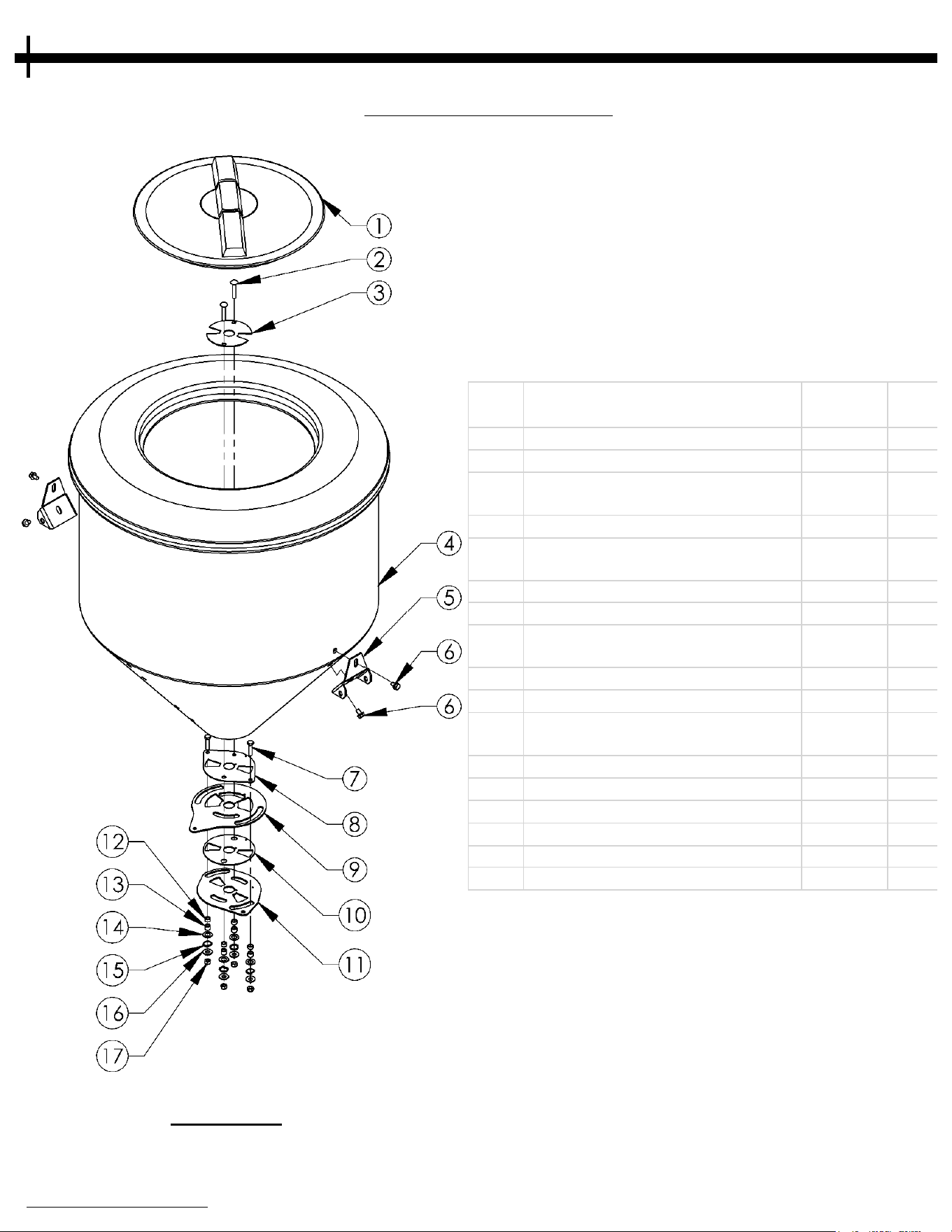
30
HOPPER ASSEMBLY
FIGURE 32.1
When ordering replacement parts
* = USE PAINT CODE: TK=BLACK
Note: Some parts not shown for clarity.
PARTS DIAGRAMS
ITEM
#
DESCRIPTION PART # QTY.
1 16" LID 22124 1
2 BOLT - CARRIAGE 5/16-18 X 1.75 20653 2
3
PLATE - HOPPER MOUNT, INNER
PLATE
21972GV 1
4 HOPPER - 52 GALLON, HPDE 21935 1
5
PLATE - HOPPER MOUNT
BRACKET
21965* 2
6 BOLT - SERR FLNG, 5/16-18 X 1/2 NB252 4
7 BOL T- HEX 5/16-18 X 1 1/4" NB504 2
8
PLATE - SLIDE PLATE, HOPPER
MOUNT
21933GV 1
9 PLATE - SPREADER, OFFSET HOLE 21936GV 1
10 PLATE - SLIDE DISC SPACER 21973GV 1
11
PLATE - SPREADER, SLIDE
OPENER
21937GV 1
12 BUSHING - 5/16"ID X 1/2" 7839Z 4
13 BUSHING - 5/16"ID X 1/2" 7825Z 4
14 WASHER - 1/2" X 14 GA NB177 4
15 SPRING - GATE, 1/2" ID 10051 4
16 WASHER - 5/16" X 1 1/4" NB556 4
17 NUT - NYLON LOCK, 5/16-18 NB181 4
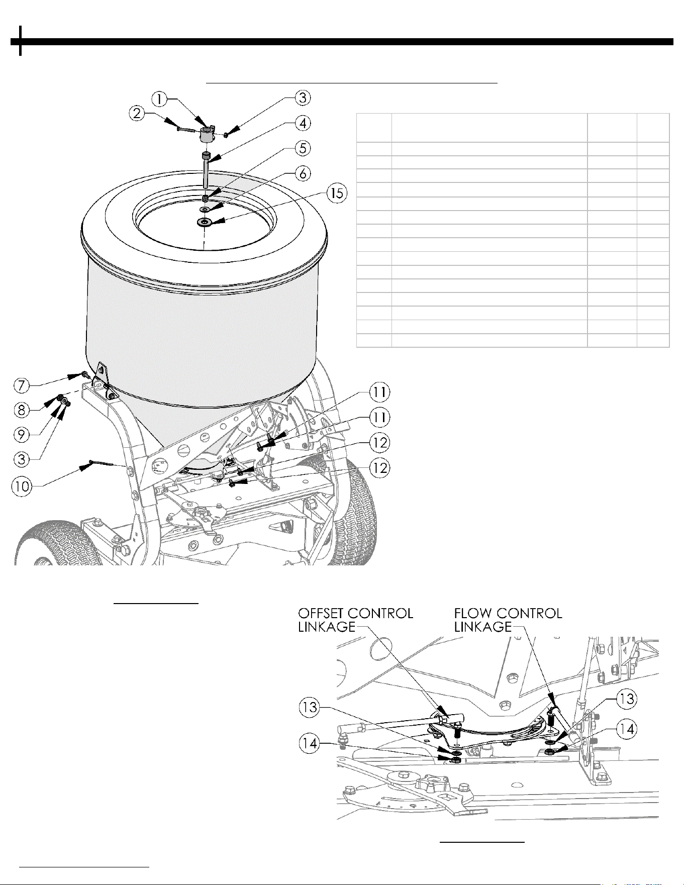
31
HOPPER MOUNTING ASSEMBLY
FIGURE 33.1
When ordering replacement parts
* = USE PAINT CODE: TK=BLACK
Note: Some parts not shown for clarity.
PARTS DIAGRAMS
ITEM
#
DESCRIPTION PART # QTY.
1 AGITATOR HEAD 21989GV 1
2
BOLT - CARRIAGE 1/4-20 X 2"
NB218
1
3 NUT - NYLON LOCK, 1/4-20 NB181 1
4 SHAFT - AGITATOR 21955GV 1
5 SPRING - 1/2" ID 12364 1
6 WASHER - 1/2" 14 GA ZP NB177 1
7 BOL T- SERR FLANGE, 5/16-18 X 1" 10548 4
8 WASHER - 5/16" LOCK NB742 4
9 WASHER - 5/16" FLAT NB556 4
10 PIN - COTTER, 3/16" X 2" 10936 1
11 BOLT - SERR FLANGE, 5/16-18 X 3/4" NB596 2
12 BOLT - SERR FLANGE, 5/16-18 X 1/2" NB252 2
13 WASHER - 5/16-18, SPLIT LOCK NB159 2
14 NUT - 5/16-24, HEX NB190 2
15 WASHER - UHMW, 3/16 THK 21967 1
FIGURE 33.2
Note: Some parts not shown for clarity.
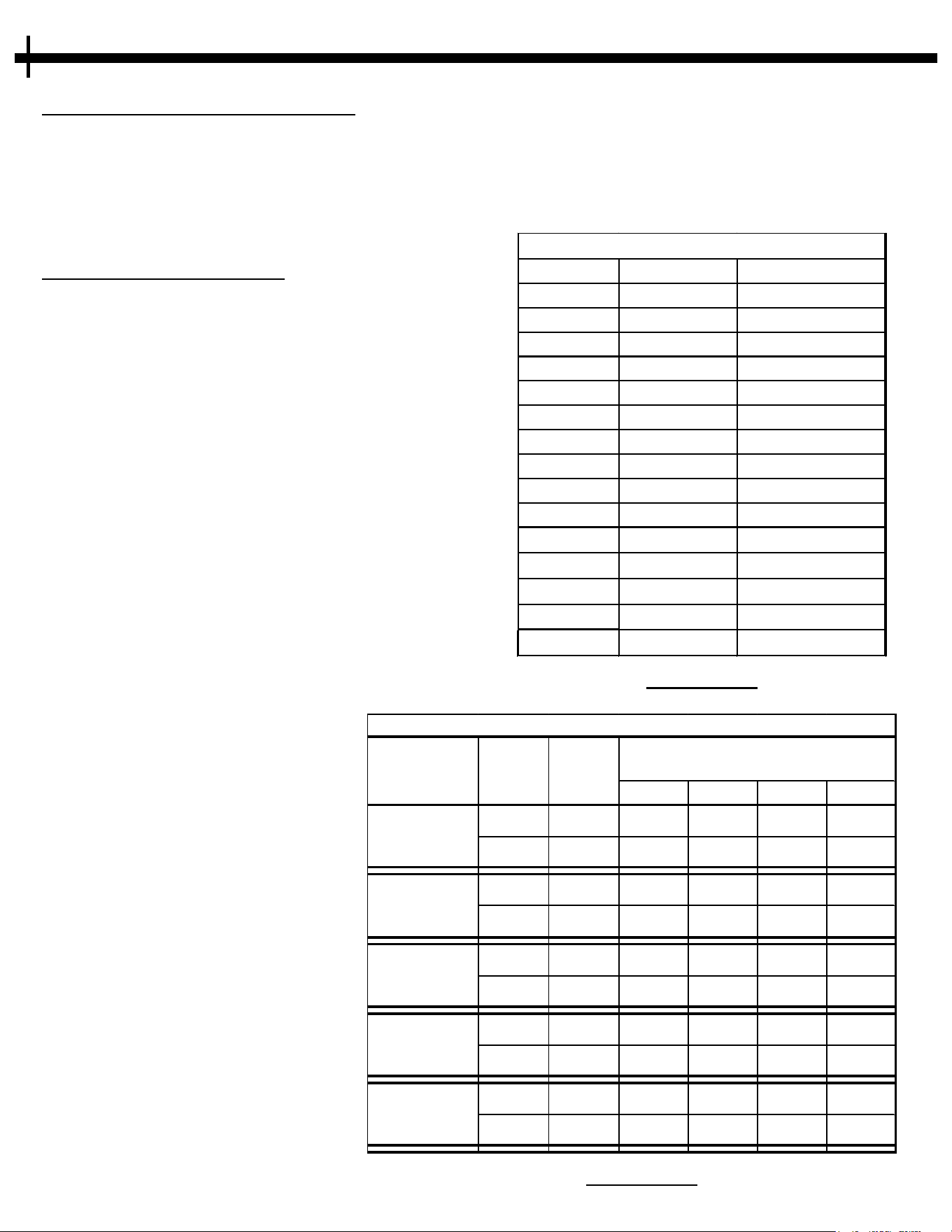
GENERAL RECOMMENDATIONS
• The chart in f
igure 32.2 only represents general guidelines for certain material flow rates.
Many factors affect how a material will spread including, but not limited too, moisture content,
ambient temperature, humidity, weather conditions, brand of medium, and many more.
• For the most accurate distribution of material, always calculate the flow rates of the material
being spread.
32
FIGURE 32.1
CALCULATING MATERIAL FLOW
Calculating Material Flow
• Fill the Hopper with a known weight of the
d
esired material. (ex. 20 lbs of seed)
• There is a graduated scale on the
Hopper. The units of measurement are
Gallons and Liters. For conversion of
Gallons to other units of volume
measurement use the Conversion Chart
FIGURE 32.1.
• Place a tarp under the spreader base to catch
the dropped material for re-use.
• Open the control gate to any desired number
and time (seconds) how long it takes for all
the material to leave the hopper. This will
give you how many pounds/second at the
setting indicated on the handle decal.
• Next it is recommended to refill the same
amount of material into the Spreader. Find an
area to spread this material where you can
GALLONS BUSHELL CUBIC FEET
4 0.43 0.53
6 0.64 0.80
8 0.86 1.07
12 1.29 1.60
16 1.72 2.14
20 2.15 2.67
24 2.58 3.21
28 3.01 3.74
32 3.44 4.28
36 3.87 4.81
40 4.30 5.35
44 4.73 5.88
46 4.94 6.15
48 5.16 6.42
52 5.59 6.95
HOPPER VOLUME CONVERSION
1
2 3 4
3 14 115
405 675 991
5 22 55
200 495 631
3 16 -
85 215 379
5 26 -
35 105 140
3 18 21
151 364 438
5 28 9
58 140 175
3 12 -
65 190 295
5 18 -
25 80 100
3 11 -
68 195 300
5 18 -
26 91 110
POUNDS /ACRE @ DIFFERENT
FLOW CONTROL SETTINGS
GENERAL MATERIAL FLOW RATES
ROCK SALT
(1/4" min)
RED
CLOVER
FESCUE
RYE
SPEED
(MPH)
MATERIAL
SAND
WIDTH
(FT)
FIGURE 32.2
see the spread width. Pull the
u
nit at the desired speed
(recommended 3-5 MPH) to
achieve the spread width that is
desired. The faster the unit is
pulled the wider the material will
be spread. The slower the unit is
pulled, the narrower the material
will spread.
• Once you have determined your
desired pulling speed, material
spread width, and material flow
rate you can calculate the pounds
per acre for accurate coverage.
Use the work sheet and notes on
pages 30-32 to log and record
flow rates for future use.
楰
ҟ
33
Material Setting Speed
Flow Rate
lbs/Second
Spread
Width
lbs/Acre
Notes
When ordering replacement parts
* = USE PAINT CODE: TK=BLACK
SPREADER LOG NOTES
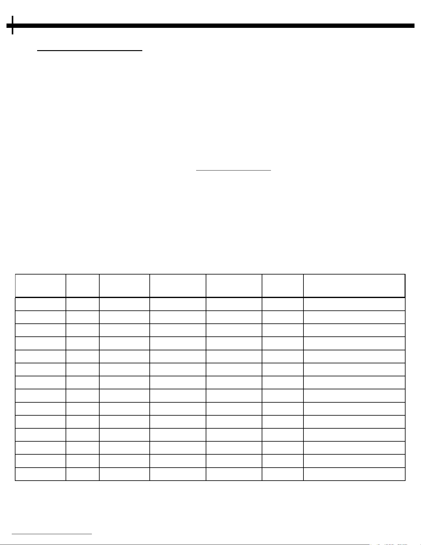
User Flow Rate Records
• Use this provided chart to keep track of current and past flow rate calculations for
f
uture use.
• Use the Notes Page 34 to write out your calculations using the following formulas for
calculating flow rates.
• Formulas to remember:
• Flow Rate (lbs/min): Material (lbs/min) that flows through selected
hopper gate setting per minute
• Coverage (sq-ft/min): Material spread width (trial test required)
multiplied by the distance traveled per minute
• (4 mph = 352 ft/min; 3 mph = 264 ft/min; 2 mph = 176 ft/min; 1 mph =
88 ft/min).
• Pounds per acre (Lbs/Acre) = Flow Rate (lbs/min)
Coverage (sq-ft/min) X 43,650 (sq.ft./acre)
•
Volume Conversions
• Gallon to bushel
• Gallons/9.309 = Bushels
• Gallon to Cu. Ft.
• Gallons/7.481 = Cu.Ft.

楰
ҟ
34
When ordering replacement parts
* = USE PAINT CODE: TK=BLACK
NOTES

Ҡ
35
When ordering replacement parts
* = USE PAINT CODE: TK=BLACK
NOTES

▀Ҡ
36

37
Hobby Farms Pro
T
ow Spreader
Each Spreader has its own model number. The model number
for the Spreader will be found on the left hand side of the
control mount platform. The model number for the gearbox
will be found on the face of the gearbox.
All Spreader parts listed herein may be ordered directly from
Swisher or your nearest Swisher dealer.
WHEN ORDERING PARTS, PLEASE HAVE THE
FOLLOWING INFORMATION AVAILABLE:
* PRODUCT – HOBBY FARM PRO TOW SPREADER
* SERIAL NUMBER - _______________
* MODEL NUMBER - _______________
* GEARBOX MODEL NUMBER - _______________
* PART NUMBER
* PART DESCRIPTION
TELEPHONE - 1-800-222-8183
FAX - 1-660-747-8650
SWISHER ACQUISITION INC.
1602 CORPORATE DRIVE
WARRENSBURG, MO 64093
www.swisherinc.com
OWNER’S
M
ANUAL
www.swisherinc.com
CHANGING YOUR LANDSCAPE SINCE 1945
IMPORTANT
R
ead and follow all
Safety Precautions
and Instructions
before operating this
equipment.
MODEL NO.
22000
38