
9/17/2020
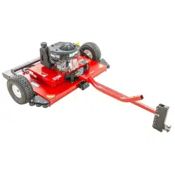
COMMERCIAL PRO
44” BRUSH KING
T
RAIL CUTTER
OWNER’S
MANUAL
SWISHER ACQUISITION INC.
1602 CORPORATE DRIVE, WARRENSBURG, MISSOURI 64093
PHONE (660) 747-8183 FAX (660) 747-8650
Assembly
Op
eration
Service and Adjustment
Repair Parts
www.swisherinc.com
MODEL NO.
S
TARTING SERIAL #:
L120-259001
RC14544CP4K
RC14544CP4K-CA
21276 REV 20-259
Re
ad and follow all
Safety Precautions
and Instructions
before operating this
equipment.
IMPORTANT
Read and follow all
S
afety Precautions
and Instructions
before operating this
equipment.
IMPORTANT
ade I The
USA
of US and Global Parts

The manufacturer’s warranty to the original consumer purchaser is: This product is free
f
rom defects in materials and workmanship for the period's shown below beginning from the
date of purchase by the original consumer purchaser. We will repair or replace, at our
discretion, parts found to be defective due to materials or workmanship. This warranty is
subject to the following limitations and exclusions:
As required by CFR § 1060.120, the fuel system related components, which have been
certified to this equipment by SAI are to be free of defects in material and workmanship for
a period of two (2) years from the date of purchase by the original consumer purchaser.
1) Engine Warranty All engines utilized on our products have a separate warranty extended to
them by the individual engine manufacturer. Any engine service warranty
is the responsibility of the engine manufacturer and in no way is Swisher or
its agents responsible for the engine warranty. The Kawasaki Engine
Service Hotline is 1-877-364-6404 or email kawpower-website@kmc-
usa.com
2) Commercial Use T
his product has a 1yr Limited Commercial - 2 Year Limited Consumer on
All Non-Engine Parts from the date of purchase.
3) Limitation This warranty applies only to products, which have been properly
assembled, adjusted, and operated in accordance with the instructions
contained within this manual. This warranty does not apply to any product
of Swisher that has been subject to alteration, misuse, abuse, improper
assembly or installation, shipping damage, or to normal wear of the product.
4) Exclusions Excluded from this warranty are normal wear, normal adjustments, and
normal maintenance.
In the event you have a claim under this warranty, you must return the product to an authorized
service dealer. All transportation charges, damage, or loss incurred during transportation of parts
submitted for replacement or repair under this warranty shall be borne by the purchaser. Should you
have any questions concerning this warranty, please contact us toll-free at 1-800-222-8183. The
model number, serial number, date of purchase, and the name of the authorized Swisher dealer from
whom you purchased the Cutter will be needed before any warranty claim can be processed.
THIS WARRANTY DOES NOT APPLY TO ANY INCIDENTAL OR CONSEQUENTIAL
DAMAGES AND ANY IMPLIED WARRANTIES ARE LIMITED TO THE SAME TIME
PERIODS STATED HEREIN FOR ALL EXPRESSED WARRANTIES. Some states do not allow
the limitation of consequential damages or limitations on how long an implied warranty may last, so
the above limitations or exclusions may not apply to you. This warranty gives you specific legal
rights and you may have other rights, which vary from state-to-state. This is a limited warranty as
defined by the Magnuson-Moss Act of 1975.
2
LIMITED WARRANTY

ҙ
3
• SAFETY PRECAUTIONS…………………………………………..………………………... 4
• KNOW YOUR CUTTER …..……………………………………………………...………….. 5
• GENERAL OPERATIONS………………..………………………………………...…….....6-8
– INTENDED USE
– ATTACHING TRAIL CUTTER TO TOW VEHICLE
– STARTING THE ENGINE
– ENGAGING BLADES
– STOPPING THE ENGINE
– BREAKING IN YOUR CUTTER
– TRANSPORTING CUTTER
– CUTTER HEIGHT ADJUSTMENT
– TOW HITCH OFFSET
– STOPPING THE CUTTING SESSION
– SUGGESTED CUTTING PRACTICES
• CUTTER MAINTENANCE……………..………………………………...…………………... 9
– GENERAL RECOMMENDATIONS
– BEFORE EACH SEASON
– BEFORE EACH USE
– DAILY MAINTENANCE
– BLADE CARE AND SERVICE
• TROUBLESHOOTING…………………………………………….……..….………………... 10
– THE ENGINE WILL NOT START
– ENGINE RUNS POORLY
– THE UNIT IS NOT CUTTING LEVEL
– CUTTER BOUNCES EXCESSIVELY WHILE TOWING
– HITCH WILL NOT PIVOT
• SPECIFICATIONS……………………………………………………….……………………. 11
• SAFETY AND OPERATION DECALS………………………………......………..….…….... 12
• ASSEMBLY PARTS…………...…………………………….....……………….….………...... 13
• SET-UP DIRECTIONS……………………………………………………………...……….… 14
• BATTERY ………………………………....................................…………………..………...... 15
• BATTERY CABLES ………………………………..................................……..…..……...….. 16
• HEIGHT ADJUSTMENT ……………………………….....………………………..…….….. 17
• HITCH OPERATION …………………………………….…………...…………………....18-19
• BLADE REPLACEMENT……………..…………………………………………….….…..… 20
• BELT REMOVAL/INSTALLATION…..………….....………….…….…………............…... 21
• PARTS DIAGRAMS …….…………………………………….………......………………..22-29
– HEIGHT ADJUSTMENT
– FRONT SKIRTING
– COVERS
– ENGINE GUARD, GAS TANK, SOLENOID
– DECK
– HITCH
– BLADE DRIVER
– ENGINE, PULLEY/BELT
– IDLER CONFIGURATION
– CONSOLE
– WIRING DIAGRAM
• CALIFORNIA EMMISIONS REQUIREMENTS……………………………………...……. 30
• SUGGESTED GUIDE FOR SLOPES ……………………………….....………………..….... 31
• ORDERING INFORMATION………………………………………………………….…….. 32
TABLE OF CONTENTSTABLE OF CONTENTS
㈰
ҙ
This Safety Alert Symbol indicates important messages in this
m
anual. When you see this symbol, carefully read the message that
follows and be alert to the possibility of personal injury.
Read this manual completely. This machine can amputate hands and feet, and throw objects. Failure
to observe the following safety instructions could result in serious injury or death.
4
• Read the manual. Learn to operate this machine safely.
• Always disconnect the spark plug wire and place the wire where it cannot contact the spark plug, to
prevent accidental starting the engine when setting up, transporting, adjusting or making repairs.
• Keep all shields and guards in place.
• Understand the speed, steering and stability of this machine. Know the positions and operations of all
controls before you operate this machine. Check all of the controls in a safe area before starting to
work with this machine.
• Allow only responsible adults who are familiar with these instructions to operate this machine. Never
allow children to operate this machine.
• Clear the area of objects such as rocks, toys, wire, etc. that can be picked up and thrown by the blade.
• Be sure the area is clear of other people before mowing. Stop the machine if anyone enters the
cutting area. Children are often attracted to the machine and the mowing activity.
Never assume that children will remain where you last saw them. Keep children under the watchful
care of another responsible adult.
• No riders!
• Do not put hands or feet near or under rotating parts.
• Do not mow in reverse. Always look down and behind before and during backing.
• Turn off the blades when not cutting. Before leaving the machine, turn off the blades and stop the
engine.
• Watch for traffic when operating near or crossing roadways.
• Do not operate the Cutter if it has been dropped or damaged in any manner or if the Cutter vibrates
excessively. Excessive vibration is an indication of damage. Repair Cutter as necessary.
• Dress properly. Do not operate the Cutter when barefoot or wearing open sandals. Wear only solid
shoes with good traction when cutting.
• Never allow operation by untrained persons.
• Do not operate the machine while under the influence of alcohol or drugs.
• Do not operate on slopes greater than 15 degrees.
• Never tamper with safety devices. Check their proper operation regularly.
• Stop and inspect the equipment if you strike an object. Repair, if necessary, before restarting. Never
make adjustments or repairs with the engine running.
• Cutter blades are sharp and can cut. Wrap the blades or wear gloves, and use extra caution when
servicing them. Do not operate at too fast a rate.
SAFETY PRECAUTIONS
Thank you for choosing Swisher’s 44” Trail Cutter. Before operating your Cutter, please
r
ead, understand and follow all of the safety precautions and other instructions explained in
this manual. As with all power equipment, lawn mowers and Cutters can be potentially
dangerous if improperly used.
5
KNOW YOUR CUTTER
** REMOVABLE COVER
• Battery, Solenoid & Wiring
a
re located under the tool-
free removable cover.
• Serial Number Tag is
located next to the battery.
Remove cover to access
serial number.
HEIGHT ADJUSTMENT
HANDLE RIGHT SIDE
HEIGHT ADJUSTMENT
HANDLE LEFT SIDE
REMOVABLE COVER
(SEE NOTE **)
OFFSET HITCH
FAN PIN
GAS TANK
WHEEL
GREASE ZERKS
OIL FILL, FILTER
& DRAIN
THROTTLE
PTO ENGAGE
SWITCH
KEY SWITCH
CONTROL CONSOLE
IMPORTANT FEATURES
OFFSET HITCH
M
AIN PIN
It is important to know the features of the Cutter. Please review the entire
m
anual for detailed operational and safety information.
6
GENERAL OPERATIONS
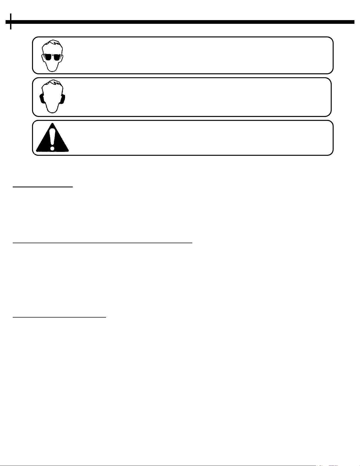
The operation of any mower can produce foreign objects to be thrown into the eyes, resulting in severe eye
d
amage. Always wear certified safety glasses or wide-vision safety goggles over spectacles before starting
any cutting machine and while operating such a machine.
The operation of any mower produces sound waves that are damaging to the human ear. Ear protection is
recommended.
CAUTION! Tragic accidents can occur if the operator is not alert to the presence of children.
Children are often attracted to the machine and the mowing activity. Never assume that children will
remain where you last saw them.
INTENDED USE
The 44” Trail Cutter is designed to clear dense areas of grass and cut saplings up to 3” thick on meadows
a
nd small estates. It is not intended to create a finish cut on lawns. Your Trail Cutter should be towed
behind an ATV, golf cart, lawn tractor or other approved vehicle. It is not recommended for speeds
exceeding 5 MPH.
ATTACHING TRAIL CUTTER TO TOW VEHICLE
• Back vehicle up to desired towing position.
•
If an offset is desired, position the Trail Cutter to the side opposite the tow vehicle discharge (if
any). This prevents the tow vehicle from throwing grass into Trail Cutter engine.
• Using the 2” ball coupler, connect the hitch to the vehicle your machine will be towed with. Once
attached, adjust the level of the Cutter by rotating the adjustment rods. See pages 17 for detailed
instructions.
STARTING THE ENGINE
See engine manufacturer’s recommendations for the type and amount of oil and fuel used. T
rail
Cutters equipped with an electric start engine will need a Battery (sold separately). Swisher recommends
using a standard “U1” battery. See pages 15 for detailed instructions.
• Make sure the tow vehicle parking brake is set, Cutter is level, and blades are
disengaged. Engine must be level to accurately check and fill oil. Do not overfill.
• Check spark plug wire, oil, and fuel.
• Check all electrical connections for buildup of debris.
• Set engine throttle to “CHOKE” position.
• Turn key to the “RUN” position, then to the “START” position.
• Set engine throttle at maximum RPM for best performance.
• Allow engine to run a few moments before engaging blades.
GENERAL OPERATIONS

䧐
ҝ
7
CAUTION: SHUT OFF THE CUTTER ENGINE AND REMOVE SPARK
P
LUG WIRE FROM SPARK PLUG BEFORE MAKING ANY
ADJUSTMENTS TO THE CUTTER.
IMPORTANT: T
his engine is not equipped with a spark arrester muffler. It is a violation of California
Public Resource Code Section 4442 to use or operate the engine on any forest-covered, brush-
covered, or grass-covered land. Other states or federal areas may have similar laws.
ENGAGING BLADES
Note: D
o not attempt to start the unit with the PTO switch in the “ENGAGED” position.
• Engage blades by pulling out on the PTO switch.
• Push PTO switch in to disengage blades.
• The braking system is applied when the blades become disengaged. It is designed to bring the
blades to a quick stop (approximately 10 seconds). The electric clutch comes with an internal
brake.
STOPPING THE ENGINE
• Make sure the tow vehicle parking brake is set.
•
Disengage cutting blades.
• Reduce engine to idle speed and allow engine to run momentarily for cooling.
• Turn the key to the off position.
BREAKING IN YOUR CUTTER
• Set the vehicle parking brake and chock the wheels to prevent accidental rolling.
•
While engine is running, engage the blade control.
• In a safe environment, (i.e. no children or pets) allow the blades to rotate and the engine to run at
full throttle for 5 minutes, breaking in the belt for longer life.
• Disengage the blades and shut off the engine.
TRANSPORTING CUTTER
• Ensure Trail Cutter is turned off.
•
Place Trail Cutter deck in its highest position.
• When transporting without the use of a tow vehicle, remove spark plug wire and place it where it
cannot contact the spark plug.
GENERAL OPERATIONS

슰
5
8
CUTTER HEIGHT ADJUSTMENT
• There is approximately 4” of height adjustment.
•
Rotate height adjust crank handle in a clockwise direction to raise the Cutter deck.
Rotate counterclockwise to lower the Cutter deck.
• Using indicator lines located on each side of the Cutter, set each side to the same height.
• Dense areas should be cut twice.
• Place handle down into the notch to lock height position.
• See Page 18 for more detailed instructions.
TOW HITCH OFFSET
• If towing with a lawn tractor, offset the rough cut Cutter to the opposite side of the lawn tractor
gr
ass discharge.
• Swisher recommends if the tow vehicle is equipped with a mid-mount Cutter to overlap the cut
approximately 6”. This may vary depending on mowing terrain, obstacles, and/or tow vehicle.
Always keep safety the first priority.
• See pages 18 & 19 for detailed instructions.
STOPPING THE CUTTING SESSION
• Bring tow vehicle to a complete stop, set the parking brake and disengage blades.
•
Turn key switch to the “OFF” position.
• Always remember to remove keys to avoid irresponsible usage.
SUGGESTED CUTTING PRACTICES
• Operate Cutter engine at full throttle to assure the best cutting performance and maximum
m
aterial discharge.
• Allow wet grass to dry. Wet grass will clump and collect under the mowing deck.
• Cutter should be started with tow vehicle in low gear and increased only as safe mowing
conditions permit. Cutting speed should not exceed 5 MPH.
• Cutting conditions and the types of grass will vary from place to place. You may find when cutting
dense areas that the pressure of the wheel tracks may cause the grass to be pushed down and not
effectively mowed. If this happens you may want to mow the area twice. Once with the Cutter
raised and the second cutting at the desired height. The second cutting should be at a right angle
from the previous for best results.
• Reducing the travel speed will help cut dense growth. This allows the blades the time necessary to
make its initial cut, and regain momentum to continue cutting. The engine may stall if you are
mowing too fast!
• Do not attempt to cut areas that the tow vehicle cannot maneuver through and/or slopes that you
do not feel comfortable riding.
GENERAL OPERATIONS

勠
Ң
CAUTION: DO NOT HANDLE CUTTER BLADES WITH BARE HANDS.
CARELESS OR IMPROPER HANDLING MAY RESULT IN SERIOUS
INJURY.
9
GENERAL RECOMMENDATIONS
The warranty on this cutter does n
ot cover items that have been subjected to operator abuse or
negligence. To receive full value from the warranty, operator must maintain unit as instructed in this
manual.
Some adjustments will need to be made periodically to maintain your unit properly. Refer to your engine
manual for recommended fuel, oil, and service parts.
BEFORE EACH SEASON
A new spark plug and clean air filter assure proper air fuel mixture and help your engine run better and
l
ast longer.
• Replace the spark plug.
• Clean or replace the air filter.
• Check blades and belts for wear.
• Add grease to wheel bearings via grease zerks.
BEFORE EACH USE
• Check engine oil level. Do this twice to ensure an accurate reading.
•
Check condition of air filter and clean or replace if necessary.
• Check blade operation.
• Check for loose fasteners.
• Lubricate threads of adjustment rods P/N 21271. See Page 22.
DAILY MAINTENANCE
Make sure all nuts and bolts are tight and cotter pins and retainer springs are secure.
K
eep blades sharp. Observe all safety precautions.
BLADE CARE AND SERVICE
For best results Cutter blades must be kept sharp. The blades can be sharpened with a few strokes of a
f
ile or grinding wheel. Do Not attempt to sharpen while on the cutter.
Important: Replace blades that have been damaged or deeply nicked.
Important: Check blade and spindle hardware on a regular basis to make sure nuts are tight.
CUTTER MAINTENANCE

勠
Ң
IF PROBLEMS PERSIST HAVE A QUALIFIED MECHANIC SERVICE
T
HE CUTTER. NEVER ATTEMPT TO MAKE AN ADJUSTMENT THAT
YOU ARE NOT SURE IS CORRECT. DOING SO CAN CAUSE OTHER
PROBLEMS.
10
TROUBLESHOOTING
ISSUE SOLUTION
Disengage blades, turn key switch to the “OFF” position,
check battery and all other electrical connections and
inspect spark plug and wire.
See Engine Manual for Troubleshooting.
Contact Engine Manufacturer or Qualified Mechanic.
See Engine Manual for Troubleshooting.
Check the Throttle Adjuster.
Check Spark Plug and Gap.
Replace fuel, Check Fuel Filter and Fuel Line.
Ensure each Height Adjustment is set to the same level.
Check Tire PSI and for tire/wheel damage.
Without the engine running, make certain blades are installed
identically and not damaged.
Decrease Tire Pressure.
Tow at a Lower Speed.
Check all Hardware and Make Sure Nothing is Overtightened.
Check for Deformed Pins.
Make sure all Moving Parts are Free of Debris.
Check tire pressure. May need to reduce PSI.
Slighty tighten the nut on top of the caster. Do not Overtighten.
Reduce Speed.
Engine Will Not Start
Engine Runs Poorly
The Unit is not Cutting Level
The Cutter Bounces Excessively
Hitch Will not Pivot
Caster Wheels Wobble
Excessively

4
Description
Engine 14.5HP (603 CC) Kawasaki
Engine Specifications
See engine Manual for Specifications
Starting
Electric Start
Battery
12 Volt ("U1" recommended), 340CCA
Fuel
2.5 Gal. (9.46 L), Unleaded Gasoline (MIN 87 Octane)
MAX 10% Ethanol
Overall Dimesions
139.5" L x 47" W x 34" H (MAX)
Console Cable Length
10' 4"
Offset Distance
(Tow ball to offset cutting edge)
Max 52", Mid 39" (See page 19 for details)
Offset Positions
5 (2 Left, 1 Center, 2 Right)
Cutting Height
3" - 7.5"
Cutting Width
44"
Blade Style
Swing Blade w/ Stump Jumper
Discharge
Rear
Drive System
Belt
Blade Engagement
Electric Clutch
Towing Speed
5 MPH MAX
Mowing Speed
5 MPH (Flat Ground) 4 MPH MAX (Rough Ground)
Unit Dry Weight
640 Lbs. (290 kg)
Tire PSI
20 PSI Recommended (MIN 15 PSI - MAX 35 PSI)
Description Part Number
Belt - B X 56"
20937
Wheel/Tire - 16/650X8
21262
Bearing - Blade; RT44
4845
Blade - Off-Set, Rough Cut
10358
Quick Reference - Maintenance Parts
Note:
•
For other part numbers, refer to the Parts Diagrams on pages 22-30.
11
SPECIFICATIONS
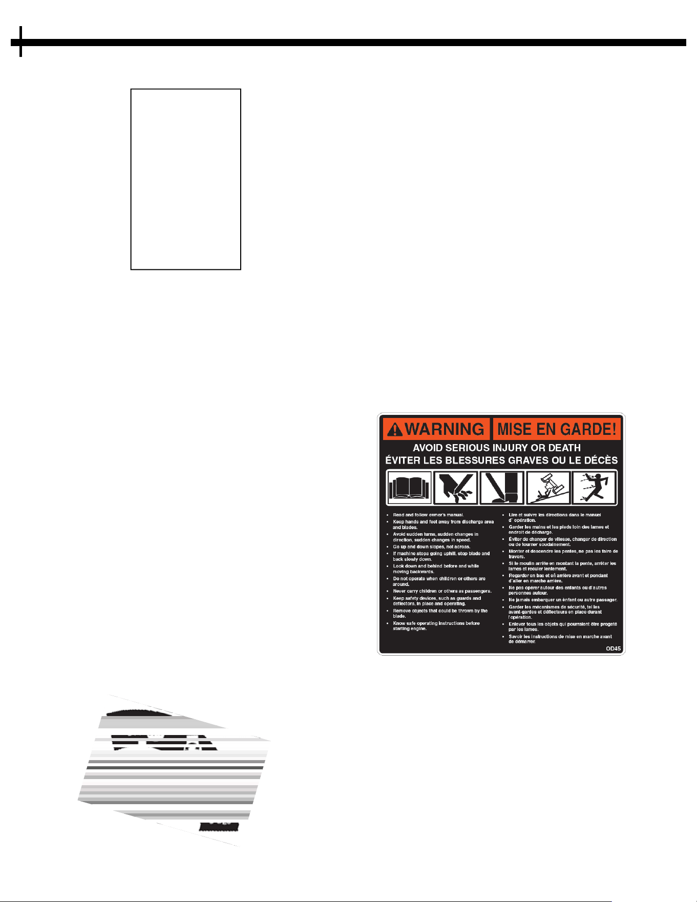
Replace decal immediately if damaged. Order by part number from
S
wisher. 1-800-222-8183, 8-5 CT M-F
OD29-DANGER DECAL
OD33-5MPH DECAL
OD36-DEFLECTOR DECAL
O
D55-DANGER DECAL
OD45-WARNING DECAL
OD129-ENGAGE DECAL
OD28-OFF/RUN/START DECAL
12
OD99112 LARGE SWISHER LOGO
SAFETY AND OPERATION DECALS
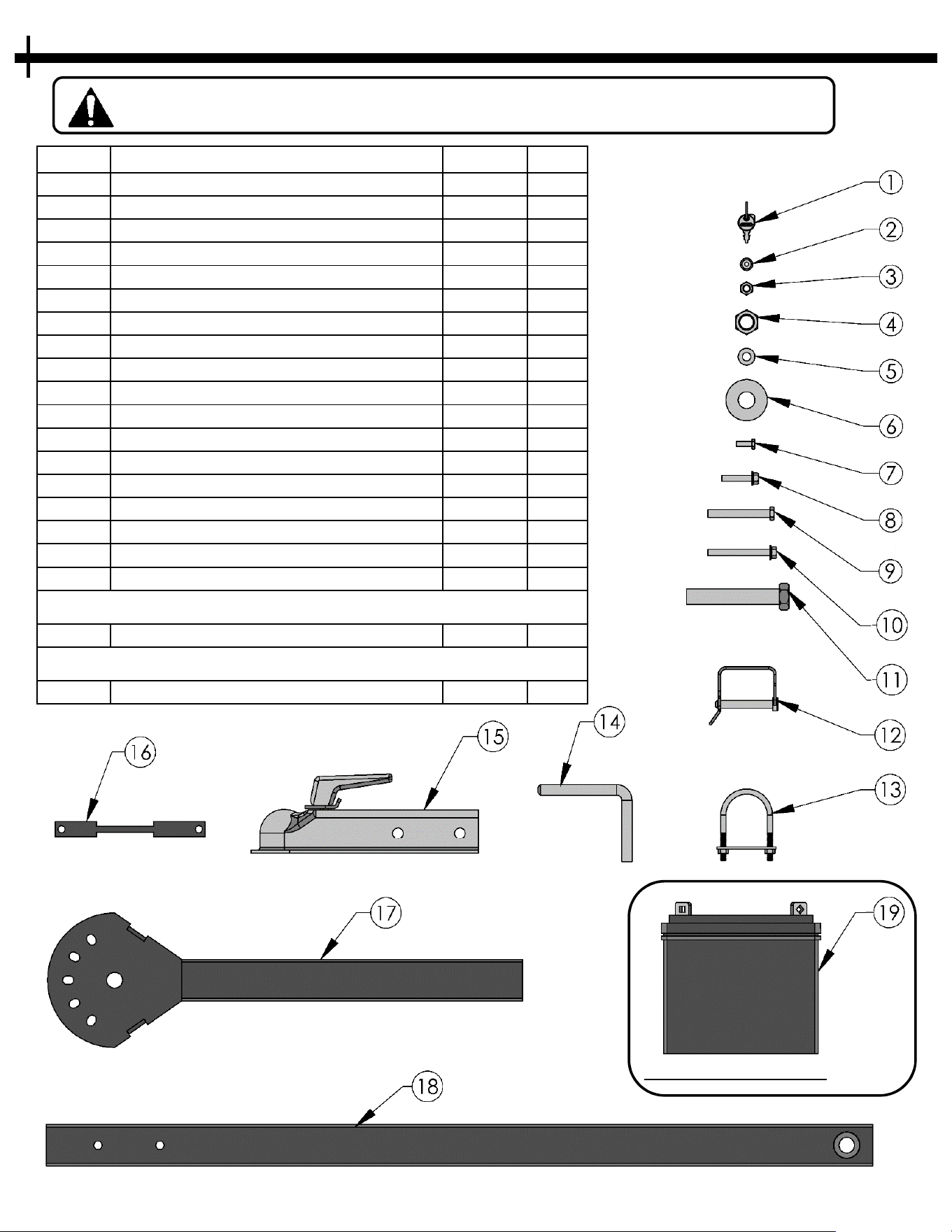
Before assembling the Cutter make sure that all assembly parts are present.
Item # Description Part # Qty
1 Key Set ( 2 Keys) KSK 1
2 Nut - 1/4-20 Flange NB524 2
3 Nut - 3/8-16 Nylon-Insert Lock NB182 2
4 Nut - 3/4-10 Nylon-Insert Lock 21132 1
5 Washer - 3/8 SAE Flat NB272 4
6 Washer - 3/4" SAE Flat NB146 2
7 Bolt - 1/4-20 X 3/4" NB250 2
8 Bolt - 5/16-18 X 1 3/4" Flange Head NB515 1
9 Bolt - 3/8-16 X 3" NB150 2
10 Bolt - Serr Flng 5/16-18 X 3 1/2" 18634 1
11 Bolt - 3/4 - 10 X 4 1/2" 21130 1
12 Pin - 3/8" X 2.5" Usable, Tab Retainer 21225 1
13 U-Bolt - 1/4-20 X 2", w/ Plate & Nuts 21231 3
14 Pin - 1/2" OD Bent 21257 1
15 2" Ball Coupler 7365 1
16 Plate - Battery Strap 21252 1
17 Weldment - Offset Hitch Tube 21117 1
18 Weldment - Hitch Bar Lower 21256 1
19 U1 Battery N/A -
- Tube - Oil Drain, Clear Plastic AS161 1
Required Parts Not Included
Included Parts Not Shown
13
ASSEMBLY PARTS
SOLD SEPARATELY

14
FIGURE 14.1
FIGURE 14.2
SET-UP DIRECTIONS
GENERAL RECOMMENDATIONS
• Use at least two people to uncrate & assemble
t
he unit. The cutter and its components are very
heavy.
UNCRATING
• Using a hammer and pry bar, separate the boards
of
the crate starting with the top. Use caution to
not damage the equipment inside the crate.
• Always wear gloves and safety glasses when
disassembling the crate.
ASSEMBLY DIRECTIONS
1. Check that all parts are present before beginning
a
ssembly. See page 13
2. Place 2” Coupler 15 over Hitch Bar 17 . Fasten
as shown using (2) 3/8-16 x 2” Bolts 9 , (4) 3/8
washers 5 , and (2) 3/8-16 lock nuts 3 .
FIGURE 14.1
3. Position Hitch Bar 18 into the Hitch Pivot
Assembly A . Attach the Hitch Bar with (1) ¾-
10 x 4 ½” Bolt 11 , (2) ¾ Washers 6 , and (1)
¾-10 Lock Nut 4 . Fasten the hardware tightly
using one 1-1/8” wrench/socket (bolt) & one
1-1/16” wrench/socket (nut). The Hitch Bar
should be able to pivot up and down freely and
have no side to side play. If the Hitch Bar will
not pivot up and down, loosen the Nut slightly.
FIGURE 14.2
4. Run the Wire Harness along the top of the Hitch
Bar 17 18 and fasten using the supplied U-
bolts 14 . Be sure to leave enough slack at the
pivot locations so hitch can freely offset
without placing tension on the wire harness.
Dimensions given are just for reference. Actual
U-bolt locations may vary by tow vehicle.
FIGURE 14.3
FIGURE 14.3
Use care when
u
ncrating.
Wrench/Socket
Q
ty. Size
(2) 9/16”
(
1) 1-1/16”
(1) 1-1/8”
(1) 7/16”
Tools Required:
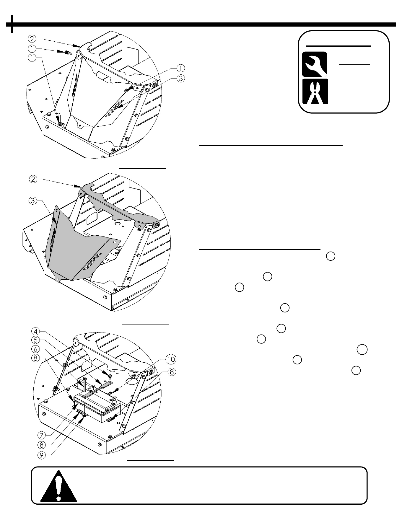
CAUTION: USE CARE HANDLING BATTERY. CARELESS OR
IMPROPER HANDLING MAY RESULT IN SERIOUS INJURY.
15
GENERAL RECOMMENDATIONS
• A standard “U1” Battery is recommended. If the
B
attery is put into service after the “month and
year” of the date on the Battery, it may need to be
charged with a 12 volt Battery charger for a
minimum of 1 hour, but no more than 2 hours at a
rate of 6 to 10 amps.
• Use pliers on Thumbscrews if they are too tight to
turn by hand. Do not re-tighten with pliers.
INSTALLATION / REMOVAL
• Remove the three Thumbscrews 1 holding the
B
attery Cover as shown in Figure 15.1.
• Tilt top Cover 2 slightly upward and slide Battery
Cover 3 down & out to remove. Figure 15.2
• Place U1 Battery into opening. Ensure the three
rubber edge guards 8 are in place before inserting
Battery. Figure 15.3
• Lay Battery strap 5 over Battery. Insert one 5/16-
18 x 1” Bolt 4 thru Battery strap hole near engine
and hand thread into the Tinnerman Clip 10 .
Insert 5/8-16 x 3” Bolt 6 thru hole in opposite end
of strap and thread into Tinnerman Clip 9 shown
in Figure 15.3. Tighten both bolts with ½” wrench
being careful not to over tighten and deform the
Battery strap.
• For removal of Battery, follow steps in reverse
order.
• See Page 16 for Battery wiring directions
Wrench/Socket
Q
ty. Size
(2) 1/2”
T
ools Required:
FIGURE 15.1
FIGURE 15.2
FIGURE 15.3
See P
age 24 for replacement part numbers
BATTERY
Pliers
(
Optional)
When ordering replacement parts
* = USE PAINT CODE: TK=BLACK
16
Engine shield not shown for Clarity
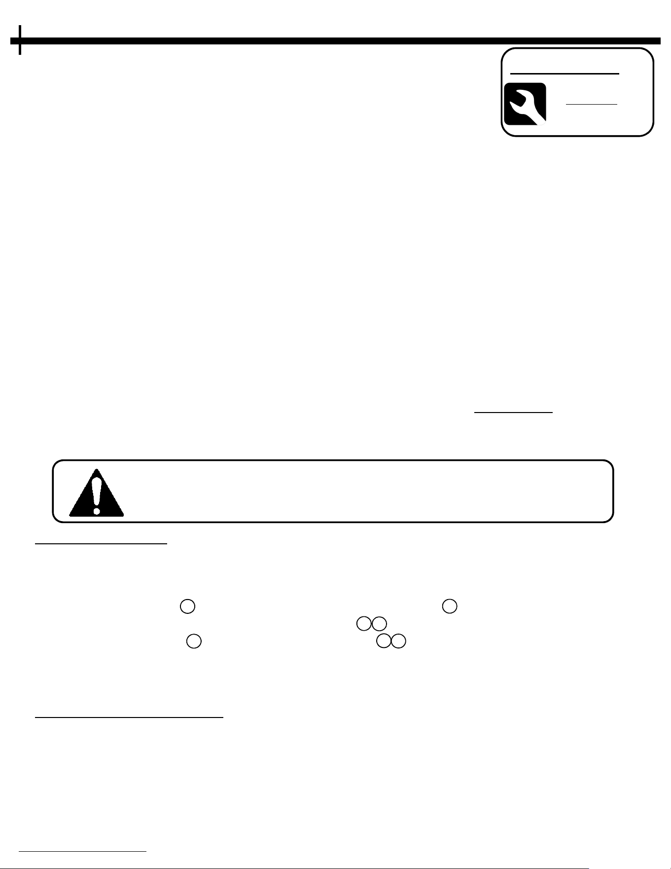
FIGURE 16.1
Cutter requires a U1 Battery (not included).
B
ATTERY WIRING
* ALWAYS CONNECT POSITIVE CABLE FIRST WHEN CONNECTING BATTERY
*
ALWAYS REMOVE NEGATIVE CABLE FIRST WHEN DISCONNECTING BATTERY
(See FIGURE 16.1)
• Locate (+) Red Cable 4 coming from Solenoid. Attach Red Cable 4 to the (+) positive terminal on
Battery and fasten with provided ¼-20 Nut and Bolt 1 2 using 7/16” wrenches.
• Locate (-) Black Cable 3 and using ¼-20 Nut and Bolt 1 2 attach it the (-) Battery terminal.
• Replace Cover and fasten with three Thumbscrews previously removed. (See Page 15)
• For removal of Battery, follow steps in reverse order.
BATTERY MAINTENANCE
• The Battery can be accessed without tools by removing the Thumbscrews holding on the front Cover.
• Keep Battery charged for best performance. Run unit for at least 45 minutes at a time to properly
charge the Battery during use.
• Clean any corrosion build-up from terminal.
• Check terminal bolts for looseness. Tighten if needed.
NOTE: The positive and negative terminals may be in a different location
on your Battery than what is shown. Image is for reference only.
Wrench/Socket
Q
ty. Size
(2) 7/16”
T
ools Required:
See P
age 24 for replacement part numbers
BATTERY CABLES
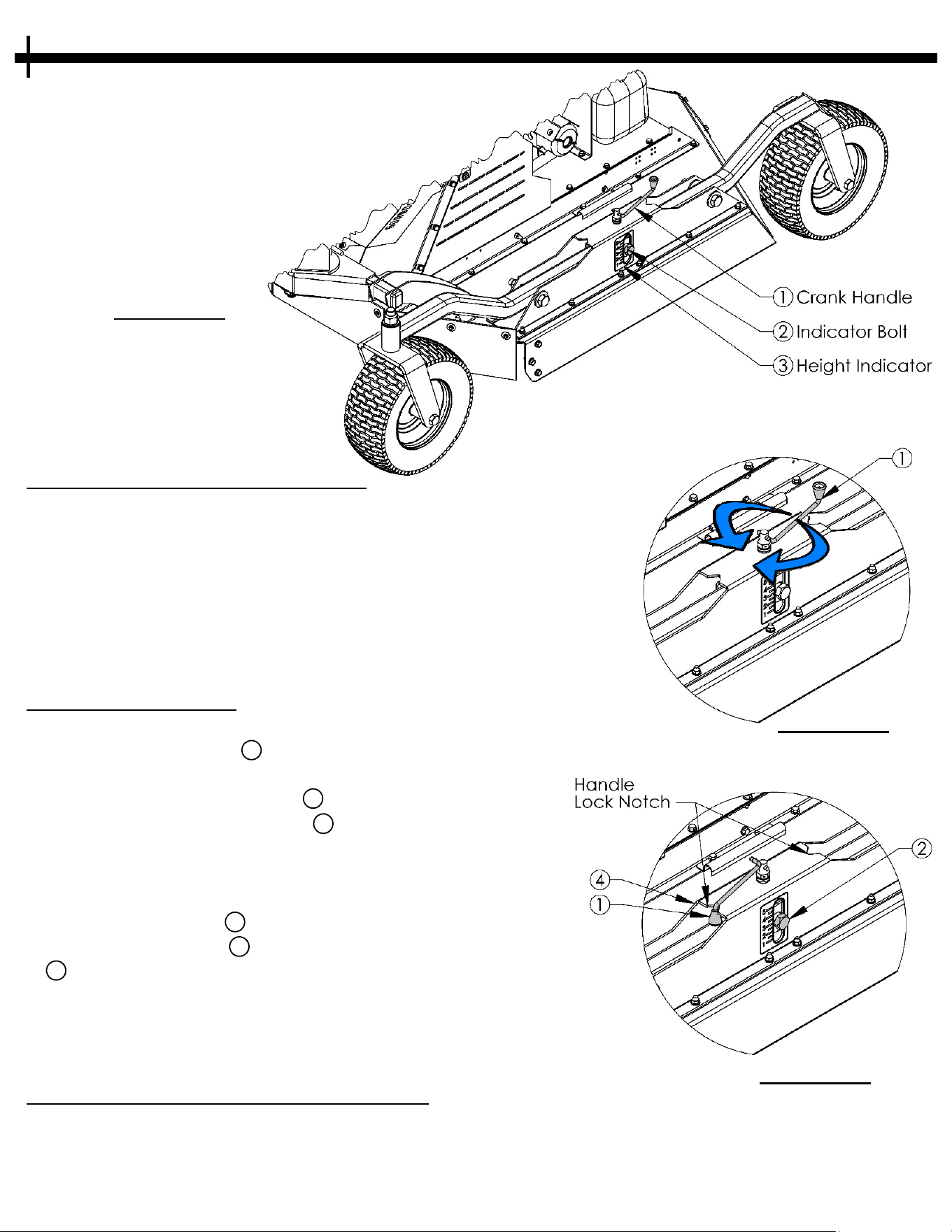
GENERAL RECOMMENDATIONS
• Set the Cutter to an appropriate height for the media being cut.
T
aller/Thicker grass & brush may require a higher first cut and a
lower second cut for best results. It’s recommended to cut the
second pass
perpendicular to the first pass.
• Height indicator decal contains number references. These
numbers do not reflect cutting height or inches. They are only a
quick reference to note where the height is set on each side of
the unit.
ADJUSTING HEIGHT
• Attach unit to the tow vehicle.
•
Find the Crank Handle 1 located on either side of the Cutter.
Figure 17.1
• To raise deck - Rotate Handle 1 clockwise. Figure 17.2
• To lower deck – Rotate Handle 1 counter-clockwise. Figure
17.2
• Lock handle at chosen height by pivoting the handle and
placing it into the notch located at either end of the Height
Adjustment Housing 4 . Figure 17.3
• Take note of the Bolt 2 location on the Height indicator Decal
3 .
• Repeat steps on opposite side of the Cutter. Ensure Bolt is in the
same location on the Height Indicator Decal on both sides. This
will help provide a level cut.
HEIGHT ADJUSTMENT MAINTENANCE
• Apply multipurpose grease/oil to Height Adjustment Threaded
Rod regularly.
• Ensure all hardware is tight and in place before each use.
• Check tires for low pressure, punctures, or wear.
17
FIGURE 17.1
FIGURE 17.2
Unlocked Crank Handle
F
IGURE 17.3
Locked Crank Handle
See P
age 22 for
replacement part numbers
HEIGHT ADJUSTMENT
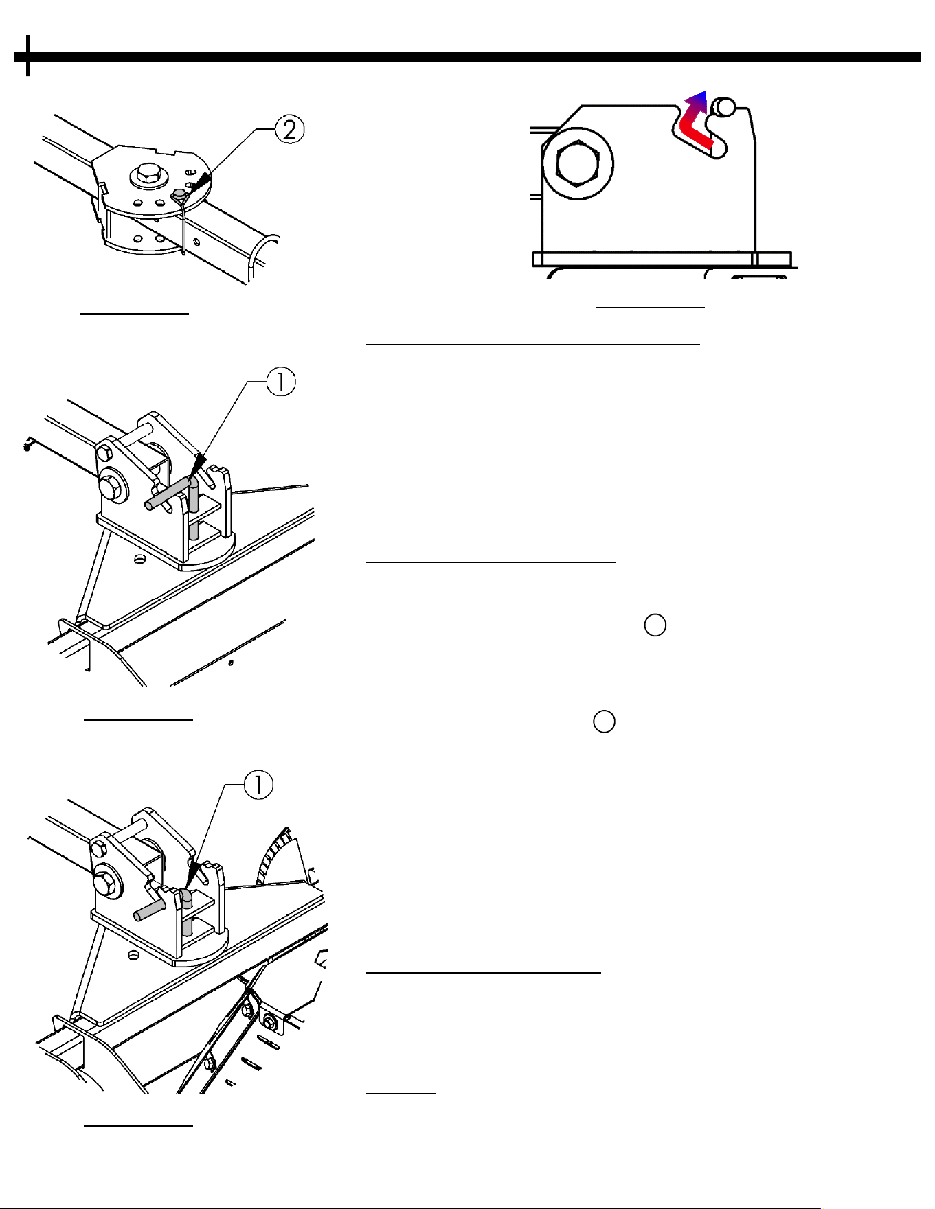
GENERAL RECOMMENDATIONS
• It is recommended to set the hitch bar in the straight position
w
hen an offset is not needed. DO NOT ADJUST HITCH ON
HILLS. The Cutter may roll once the pins are removed on a
slope. This can cause injury or damage the equipment.
• The unit can be unattached from the tow vehicle for easier
adjustment of the hitch. Be sure to detach the console from the
tow unit to avoid damage to the wiring harness.
ADJUSTING THE OFFSET
• Place cutting unit on a level area where the Cutter will not roll
by
itself.
• Unlatch & remove the 3/8” Pin 2 located in the center of the
Hitch Bar. Figure 18.1
• Rotate Hitch Arm until the desired offset location is achieved.
Reinstall 3/8” Pin and lock retainer. Figure 18.1
• Next, remove the ½” Pin 1 by guiding handle of Pin through
the slot. The Pin only needs to come out enough to rest on the
notch as shown. Figure 18.4
• The hitch bar will now be free to rotate to the desired offset
side.
• Once the hitch bar is close to the desired offset location, slide
the Pin handle back in the slot. To lock the Pin, simply rotate
the hitch bar slightly until the Pin falls into place by itself.
Figure 18.3
HITCH MAINTENANCE
• Apply grease to Hitch pivot points to ensure free movement.
•
Ensure all hardware is tight and in place before each use.
• Check locking pins for deformation or damage.
NOTES
• If the locking pins are difficult to remove it may be required to
slightly rock the hitch side to side to relieve any pressure that
may be on the pins.
FIGURE 18.1
FIGURE 18.2
Unlocked Pin
F
IGURE 18.3
Locked Pin
18
See Page 26 for
replacement part numbers
HITCH OPERATIONS
FIGURE 18.4
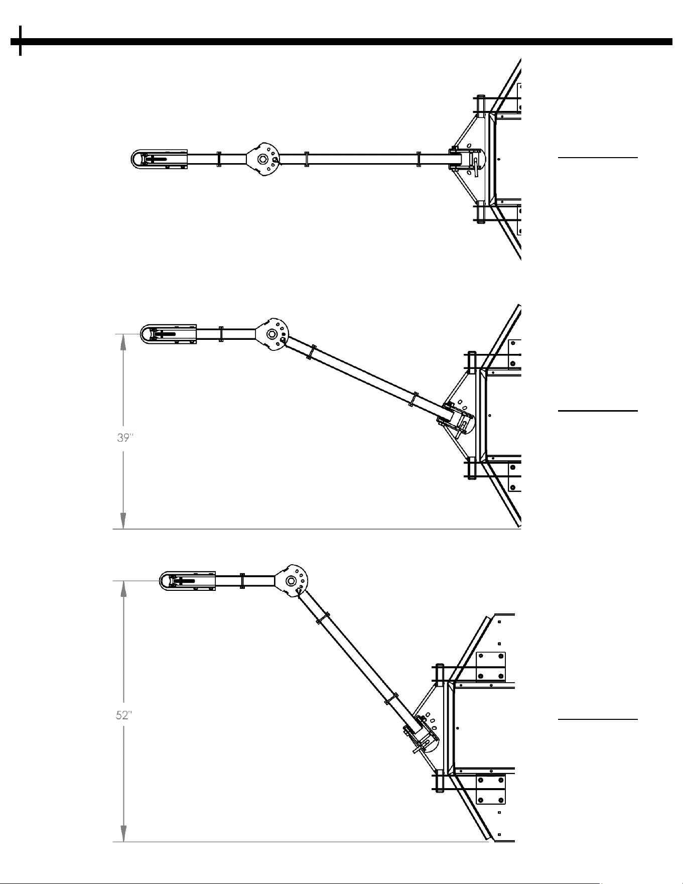
FIGURE 19.1
Centered
19
S
ee Page 26 for replacement part numbers
HITCH OPERATIONS
FIGURE 19.2
Mid Offset
F
IGURE 19.3
Max Offset
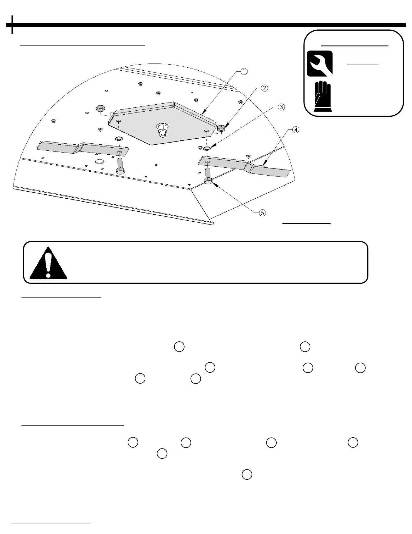
BLADE REPLACEMENT
When ordering replacement parts
* = USE PAINT CODE: TK=BLACK
20
FIGURE 20.1
BLADE REMOVAL
(See F
IGURE 20.1)
• Disconnect spark plug wire before working on unit!
• Use Jack Stands or ramps to lift the Cutter off of the ground. Chock the wheels to prevent the Cutter
from moving.
• Using the 1-1/8” wrench loosen the Nut 2 on the top of the Stump Jumper 1 . After loose, hold nut in
place with wrench.
• Using the 1-1/8” wrench/socket remove the Bolt 5 from the Stump Jumper 1 . The Blade 4 should
come off along with the Bolt 5 and Washer 3 . Ensure no body parts are under the Blade to avoid
possible injury.
• Repeat steps for both blades.
BLADE INSTALLATION
(See F
IGURE 20.1) **Apply Blue Thread Locking Compound to all Threads**
• Hold new/sharpened blade 4 and washer 3 up to Stump Jumper 1 and thread the Bolt 5 into the
tapped hole in the Stumper Jumper 1 .
• Tighten the Bolt until snug. Back off ¼ turn to allow the Swing Blade to pivot freely around the Bolt.
• Hold Bolt with one 1 1/8” wrench and thread the Lock Nut 2 onto to Bolt and tighten securely against
the top of the Stump Jumper using second 1 1/8” wrench. Torque to 150 ft.lbs.
• Check that Bolt feels tight and that the blade can pivot freely around the Bolt.
• Repeat steps for both blades.
Wear gloves when handling the blades and when using tools around the
blades. Always be aware of the sharp edges of blades. Use caution when
turning wrench to remove & install blade bolts.
• W
rench/Socket
Qty. Size
(2) 1 1/8”
T
ools Required:
• G
loves
See P
age 27 for replacement part numbers
BLADE REPLACEMENT
ݠң
When ordering replacement parts
* = USE PAINT CODE: TK=BLACK
21
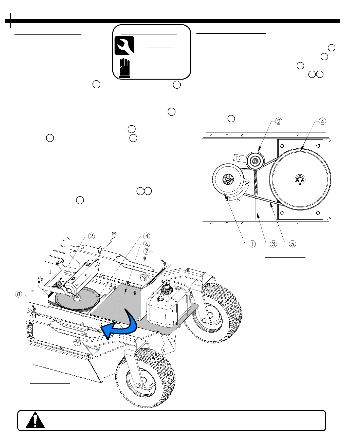
REMOVING BELT
(See F
IGURE 21.2)
• Disconnect negative Battery
• terminal before working on
• the Cutter.
• Locate the six Screws 7 securing the Belt Cover 6 .
Using the 9/16” wrench/socket, remove the screws.
• Carefully slide Cover to the fuel line side of the Cutter
deck and set out of the way of the Blade Pulley 4 . Do
not place tension on the fuel lines.
• Wearing Gloves, remove the Belt 5 from the Engine
Pulley 1 and Blade Driver Pulley 4 by rotating the
Driver Pulley and rolling the Belt over the edge as you
rotate.
• Once the Belt is loose, remove it from the Engine
Pulley and remove the Belt from the Cutter.
• If Belt is too difficult to roll off, you may need to
loosen the tension of the Idler Pulley 2 3 . Loosen the
Idler Spring Nut 8 until the Belt can be removed. Be
sure to re-tighten the Nut when the new Belt is
installed. Check for proper belt tension after
tightening.
NOTE: Use caution when moving gas tank. Wait until muffler has cooled before
attempting work on the belt.
• W
rench/Socket
Qty. Size
(1) 9/16”
(
1) 1/2”
Tools Required:
FIGURE 21.2
INSTALLING BELT
(See F
IGURE 21.1)
• Wrap new Belt around the Engine Pulley 1 .
• Wrap the Belt around the Blade Pulley 4 .
• Place Belt against Idler Pulley 2 and
reapply tension to the Idler Spring 3 8 if
required.
• Check to ensure Belt is properly seated on
all pulleys.
• Replace Cover and fasten with removed
Screws 7 .
See Page 27 & 28 for
replacement part numbers
See Page 23, 27 & 28 for
replacement part numbers
BELT REMOVAL/INSTALLATIONBELT REMOVAL/INSTALLATION
FIGURE 21.1
• G
loves
22
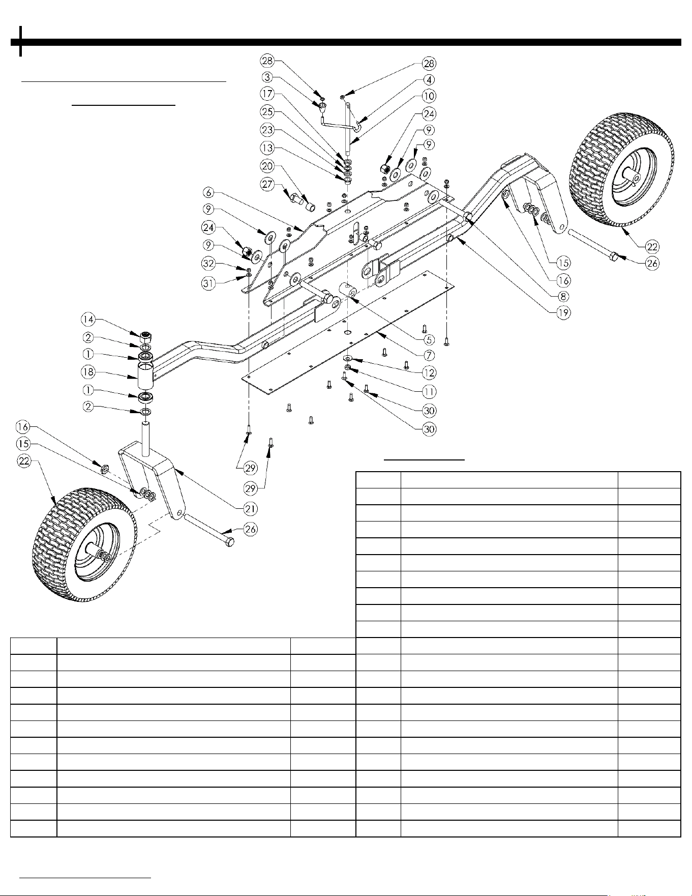
Item # Description Part #
12 Washer - Belleville, .512x1.26 10291
13 Bearing - Flanged Sleeve 5/8ID 21246
14 Nut - Nylon Lock, 1"-8 NB612
15 Washer - 3/4ID X 1 1/4OD, Flat NB184Z
16 Nut - Nylon Lock Jam, 3/4-10 NB313
17 Nut - Lock Jam, 2 Way 5/8-11 NB595
18 Weldment - Caster Arm 21217*
19
Weldment - Rigid Wheel Arm 21220*
20 Tube - Height Adjust Bushing 21245Z
21
Weldment - Caster Assembly 21258*
22 Wheel/Tire - 16/650X8, W/Sealant 21262
23 Washer - HDPE, Ø5/8" ID 21269
24 Nut - Nylon Lock, 3/4"-10 21132
25 Washer - 5/8 ID X 1 OD 14 GA NB149
26 Bolt - Hex 3/4-10 X 8 1/2" 21272
27 Bolt - Hex 3/4"- 16 X 1 1/4" 21228
28 Nut - Push, 5/16 NB117
29 Bolt - Carriage 5/16-18 x 1 1/4 10217
30 Bolt - Carriage 5/16-18 x 1 10197
31 Washer - 5/16 SAE Flat NB275
32 Nut - Nylon Lock, 5/16-18 NB181
When ordering replacement parts
* = USE PAINT CODE: TK=BLACK
FIGURE 22.1
HEIGHT ADJUSTMENT
ASSEMBLY
Note: Some parts not shown for clarity.
PARTS DIAGRAMSPARTS DIAGRAMS
Item # Description Part #
1 Bearing - Blade, RT44 4845
2 Washer - 1 X 1 1/2 10 GA NB614HT
3 Knob - Height Adjustment H7K
4 Rod - Crank, .313" OD 21270
5 Bar - Center Pivot Threaded 21243Z
6 Bracket - Height Adjustment 21224*
7 Plate - Bottom Cover Base 21223*
8 Bolt - Hex 3/4-10 X 5" NB243
9 Washer - 3/4" SAE Flat NB146
10 Rod - Dual Thread, 5/8-11, 1/2-13 21271
11 Nut - 1/2-13 2-Way Jam Lock NB121
When ordering replacement parts
* = USE PAINT CODE: TK=BLACK
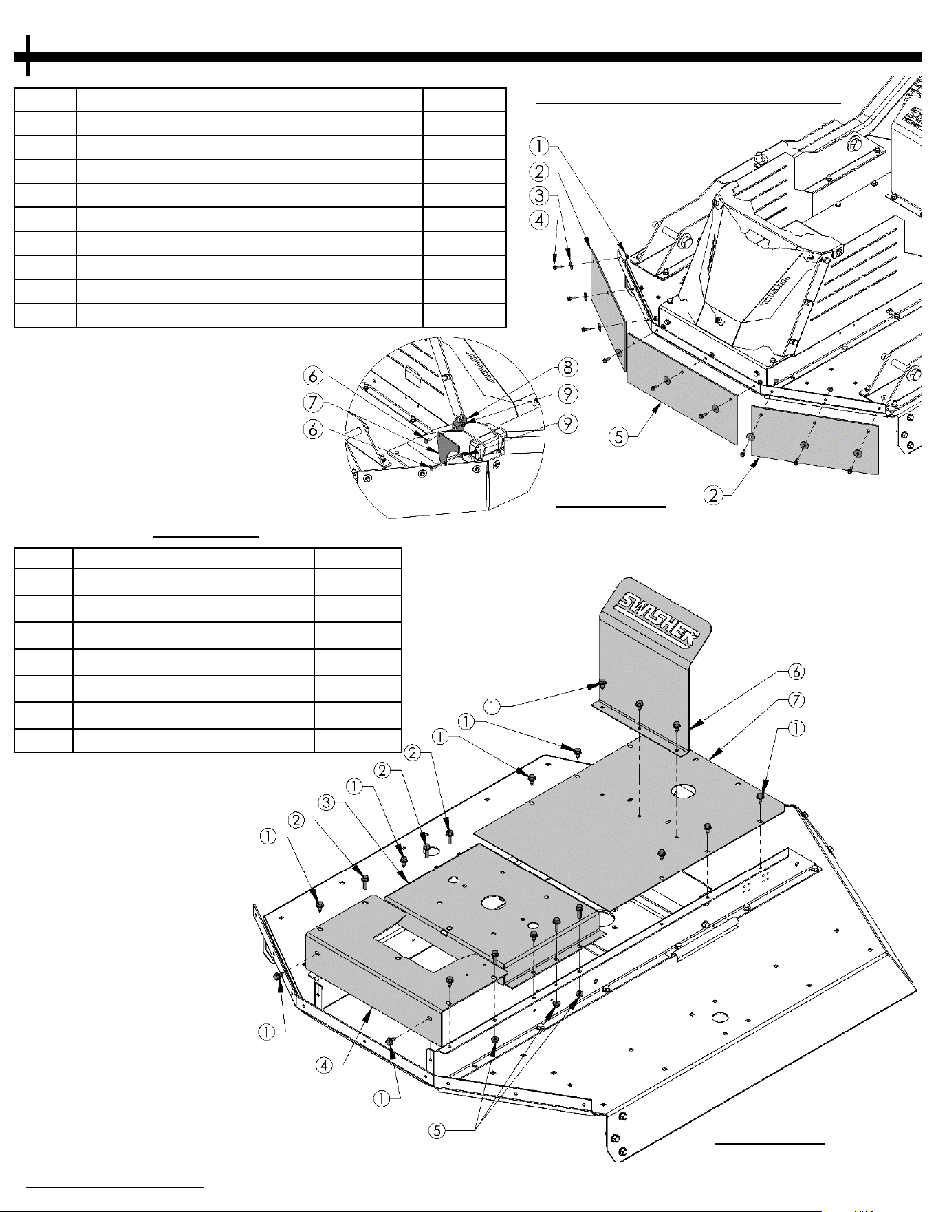
Item # Description Part #
1 Nut - Serr Flange, 1/4-20 NB524
2 Debris Guard - Outer 21233
3 Washer - Fender, 1/4X1 1/4OD 11520
4 Bolt - Serr Flange, 1/4-20 X 3/4 NB690
5 Debris Guard - Center 21234
6 Bolt - Carriage, 1/4-20 10547
7 Plate - Harness, Mount Support 21274*
8 Plate - Harness, Cable Support 21260*
9 Nut - Nylon Lock, 1/4-20 NB180
FRONT SKIRT ASSEMBLY
FIGURE 23.1
23
COVERS
FIGURE 23.2
Note: Some parts not shown for clarity.
Item #
Description
Part #
1 Screw - .312-18 x .75, Black 26X249
2 Bolt - Serr. Flange, 5/16-18 10548
3 Weldment - Motor Mount 21248*
4 Plate - Battery Mount 21268*
5 Nut - Serr. Flange, 5/16-18 NB170
6 Guard - Fuel Tank 20938*
7
Cover - Gas Tank Mount
21249*
PARTS DIAGRAMS
Item # Description Part #
21 Plate - Battery Strap 21252*
22 Cable - Black BCS
23 Nut - M8-1.25 NB718
24 Cable - Red BCSR
25 Bolt - M8-1.25 X 20mm NB719
26 Bolt - TCS 1/4-20 X 1/2 NB114
27 Solenoid - 3 Pole 1002004
28 Battery Pad BATPAD
FIGURE 24.1
24
When ordering replacement parts
* = USE PAINT CODE: TK=BLACK Note: Some parts not shown for clarity.
FIGURE 24.2
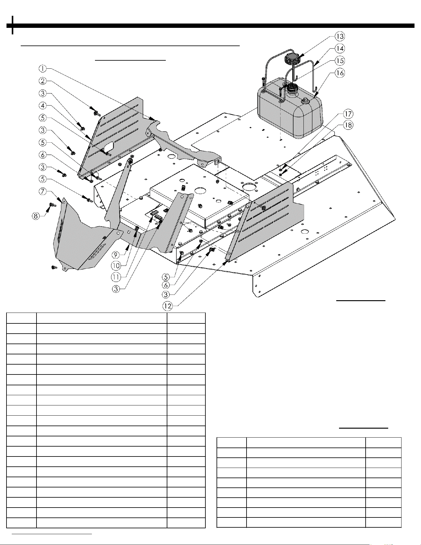
Item # Description Part #
1 Cover - RC Engine Guard 21263*
2 Bolt - Shoulder, 5/16-18 NB743
3 Clip - Tinnerman, 5/16-18 3706
4 Guard - Engine Right Side 21267*
5 Bolt - Serr. Flange, 5/16-18 NB596
6 Nut - Serr. Flange, 5/16-18 NB170
7 Guard - Battery Access Panel 21264*
8 Screw - Thumb, Shoulder; 5/16-18 18802
9 Guard - RC Engine 21265*
10 Cage Nut - 5/16-18 21087
11 Edge Trim - TrimLok, Black, 2" AS116
12 Guard - Engine Left Side 21266*
13 Cap - Fuel Tank, Carb Sealed 18221
14 Bracket - Fuel Tank 18225
15 Bolt - Serr. Flange, 1/4-20 18236
16 Fuel Tank - 2.5 Gallon 18214
17 Washer - 1/4 SAE Flat NB274
18 Nut - Nylon Lock, 1/4-20 NB180
19 Bolt - Serr. Flange 5/16-18 x 1 3/4" NB515
20 Bolt - Serr. Flange, 5/16-18 18580
ENGINE GUARD,GAS TANK, SOLENOID
ASSEMBLIES
PARTS DIAGRAMS
25
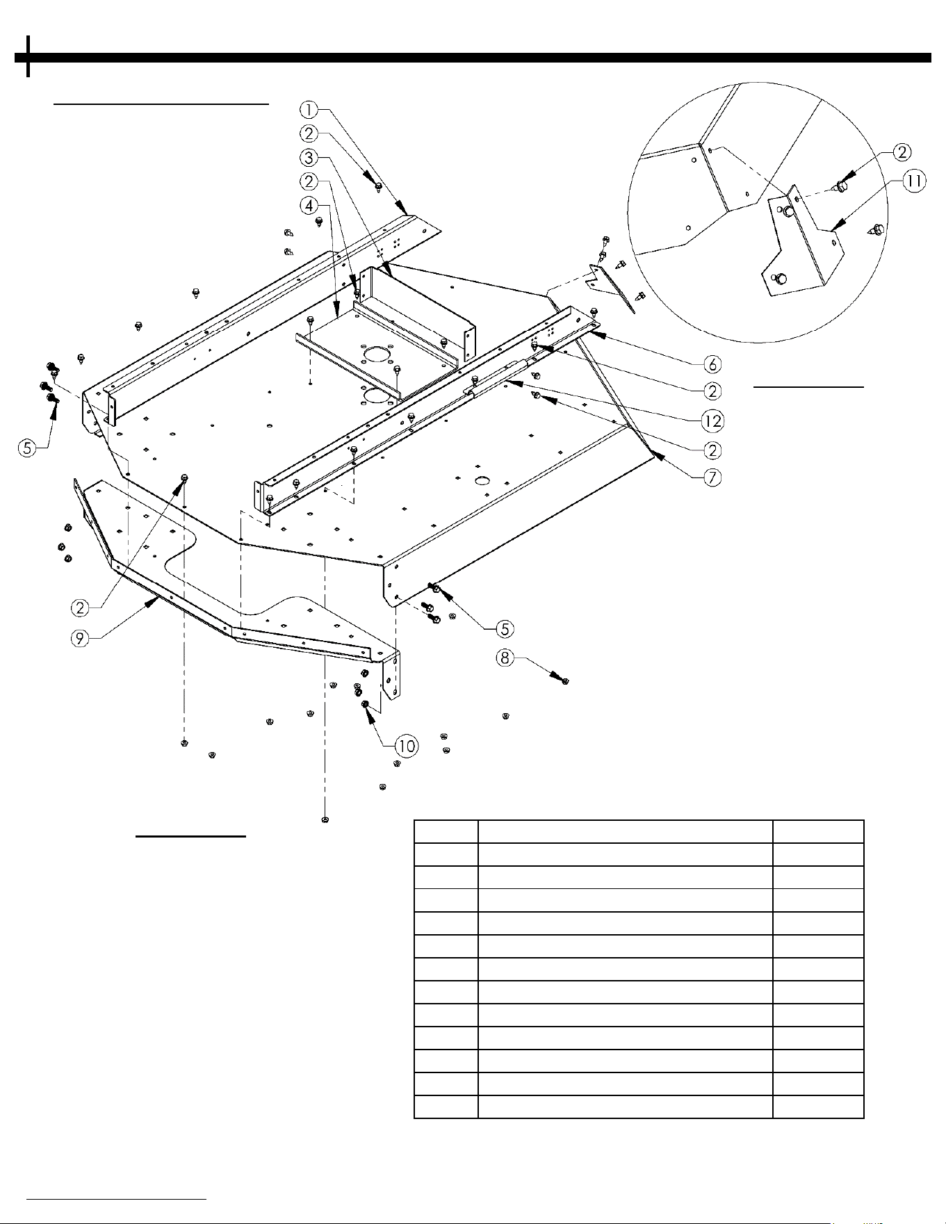
Item # Description Part #
1 Plate - Motor Mount Rail Right 21251*
2 Screw - .312-18 X .75, Black 26X249
3 Brace - Rear Z-Rail 16371*
4 Plate - Blade Support 15058*
5 Bolt - Serr. Flange, 3/8-16 13964
6 Plate - Motor Mount Rail Left 21250*
7 Weldment - Deck Body 21230*
8 Nut - Serr. Flange, 5/16-18 NB170
9 Plate - Debris Guard Support 21227*
10 Nut - Serr. Flange, 3/8-16 19799
11 Plate - Rear Deck Reinforce 21242*
12 Shield - Heat, Fuel Line 6052*
DECK ASSEMBLY
FIGURE 25.1
When ordering replacement parts
* = USE PAINT CODE: TK=BLACK
Note: Some parts not shown for clarity.
FIGURE 25.2
PARTS DIAGRAMS

26
Item # Description Part #
1 Bolt - Hex, 3/4-10 21129
2 Washer - 3/4" SAE NB146
3 Pin - 3/8", Tab Retainer 21225
4 2" Ball Coupler 7365
5 Bolt - Hex, 3/8-16 NB150
6 Washer - 3/8" SAE NB272
7 Nut - Nylon Lock, 3/4-10 21132
8 Weldment - Offset Hitch Tube 21117*
9 Nut - Nylon Lock, 3/8-16 NB182
10 Pin - Pivot Latch 21257Z
11 Weldment - Hitch Pivot Assembly 21253*
12 Bolt - Hex, 3/4-10 21130
13
Bushing - Machine; 1" ID X 2" OD X .048" Thck 21121
14
Plug - 1 1/2" X 2" , Plastic 21127
15 Hitch - Weldment Assembly 21235*
16 Washer - USS Flat, Ø1" NB569
17 Washer - Belleville 1" NB738
18 Nut - 1"-8 Toplock 21163
19 Bolt - Carriage, 3/8-16 19829
20 Weldment - Hitch Tube Rear 21256*
21 Nut - Lock, 1/2-13 NB121
22 Bolt - Hex 1/2-13 x 4" NB132
HITCH ASSEMBLY
FIGURE 26.1
When ordering replacement parts
* = USE PAINT CODE: TK=BLACK
Note: Some parts not shown for clarity.
PARTS DIAGRAMS

BLADE DRIVER ASSEMBLY
FIGURE 27.1
Item # Description Part #
1 Nut - Nylon Lock, 1"-8 NB612
2 Washer - 1" X 2" X 14GA NB738
3 Pulley - Blade, 12" OD 20920
4 Spacer - Pulley 21344
5 Bearing - Blade 4845
6 Shaft - Blade 18844
7 Nut - Nylon Lock, 1/2"-13 NB281
8 Washer - USS Flat, 1/2" NB555
9 Blade Driver Housing 4858*
10 Bolt - Hex 1/2"-13 X 2" NB509
11 Cover - Dust, RC Housing 21372
12 Washer - Flat, 1" X 1 1/2" NB614HT
13 Nut - Nylon Lock, 3/4"-10 NB609
14 Weldment - Stump Jumper 4859*
15 Washer - Flat, 3/4" X 1 1/4" NB179
16 Blade - Off-Set, Rough Cut 10358
17 Bolt - Hex, 3/4-10 X 2" 11431
18 Nut - Nylon Lock, 1"-14 18850
19 Kit - Replacement, Blade Driver 18905
When ordering replacement parts
* = USE PAINT CODE: TK=BLACK
Note: The pulley, stump jumper, blades, blade hardware
and housing hardware are not included with the 18905
replacement blade driver kit.
27
Note: Some parts not shown for clarity.
PARTS DIAGRAMS
28
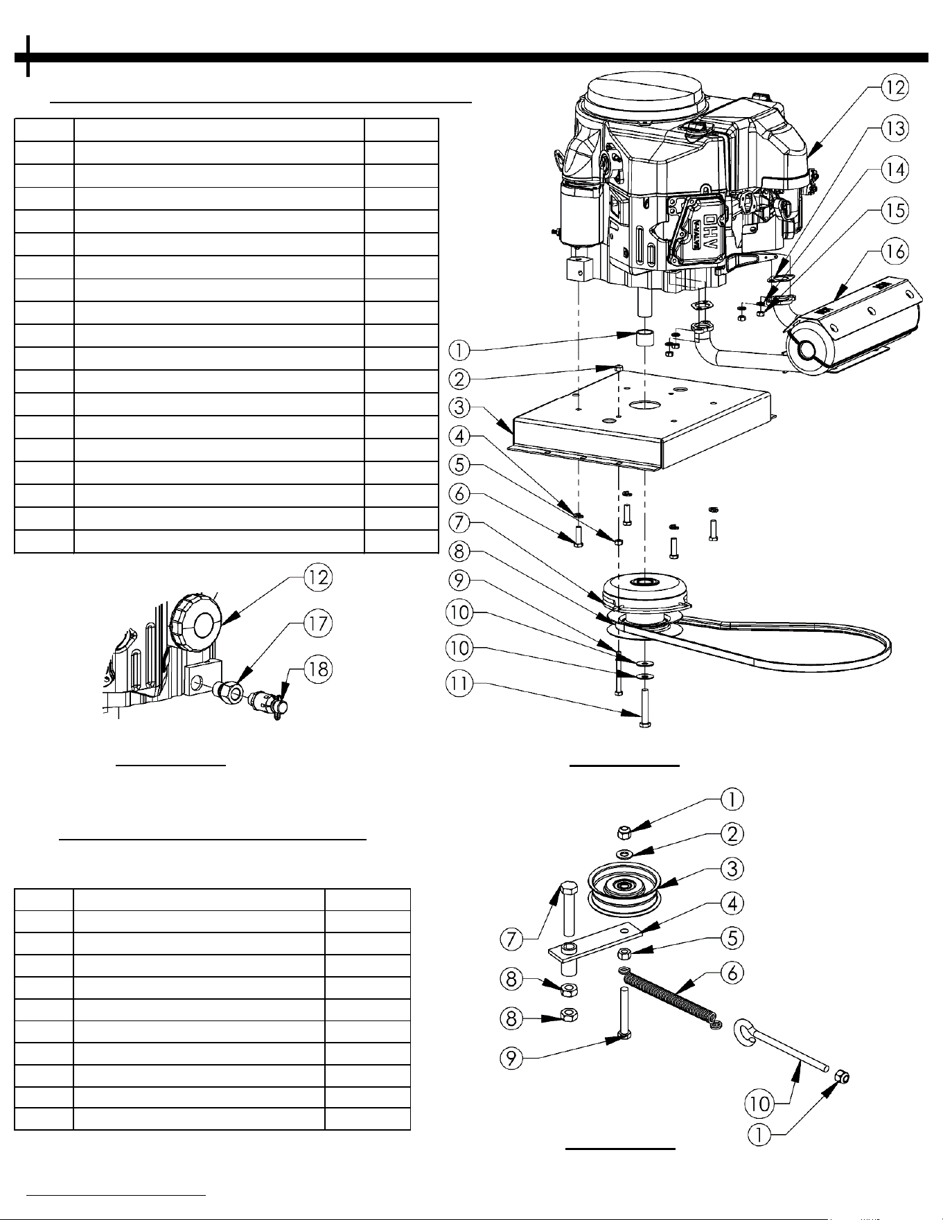
ENGINE PULLEY/BELT ASSEMBLY
Item # Description Part #
1 Nut - Nylon Lock, 3/8-16 NB182
2 Washer - SAE Flat 3/8 NB272
3 Pulley - Idler, OD3.25" ID3/8" B527
4 Idler - Weldment 21285*
5 Nut - Hex, 3/8-16 NB212
6 Spring - Clutch Rod 682S
7 Bolt - Hex, 1/2-13 X 2 1/2 NB510
8 Nut - Jam Lock, 1/2-13 2-Way NB121
9 Bolt - Hex, 3/8-16 X 2 1/2 NB619
10 Eyebolt - Turned 3/8-16 X 5 11223
FIGURE 28.3
IDLER CONFIGURATION
Item # Description Part #
1 Spacer - 1.032 ID X .90 L 20572*
2
Nut - Nylon Lock, 5/16-18
NB181
3 Weldment - Motor Mount 21248*
4 Washer - Split Lock, 3/8" NB711
5 Nut - Locking, 2 Way 5/16-18 NB558
6 Bolt - Hex 3/8-16 X 1 1/4 NB618
7 Clutch - Electric, 1" Crank 3813
8 Belt - B X 56" 20937
9 Bolt - Hex, 5/16-18 X 3" NB563
10 Washer - Belleville 7/16 X 1 1/4 699
11 Bolt - Hex, 7/16-20 X 2.5" NB685
12 Engine -14.5Hp Kawasaki 20918
13 Gasket - Kawasaki Muffler N/A
14 Washer - M8, Split-Lock N/A
15 Nut - M8 X 1.25 N/A
16
Muffler - Kawasaki, 14.5Hp FS481V
20919
17 Adapter - Oil Drain, Kawasaki 18810
18 Valve - Oil Drain 16000
When ordering replacement parts
* = USE PAINT CODE: TK=BLACK
Note: Some parts not shown for clarity.
FIGURE 28.2
FIGURE 28.1
PARTS DIAGRAMS
29
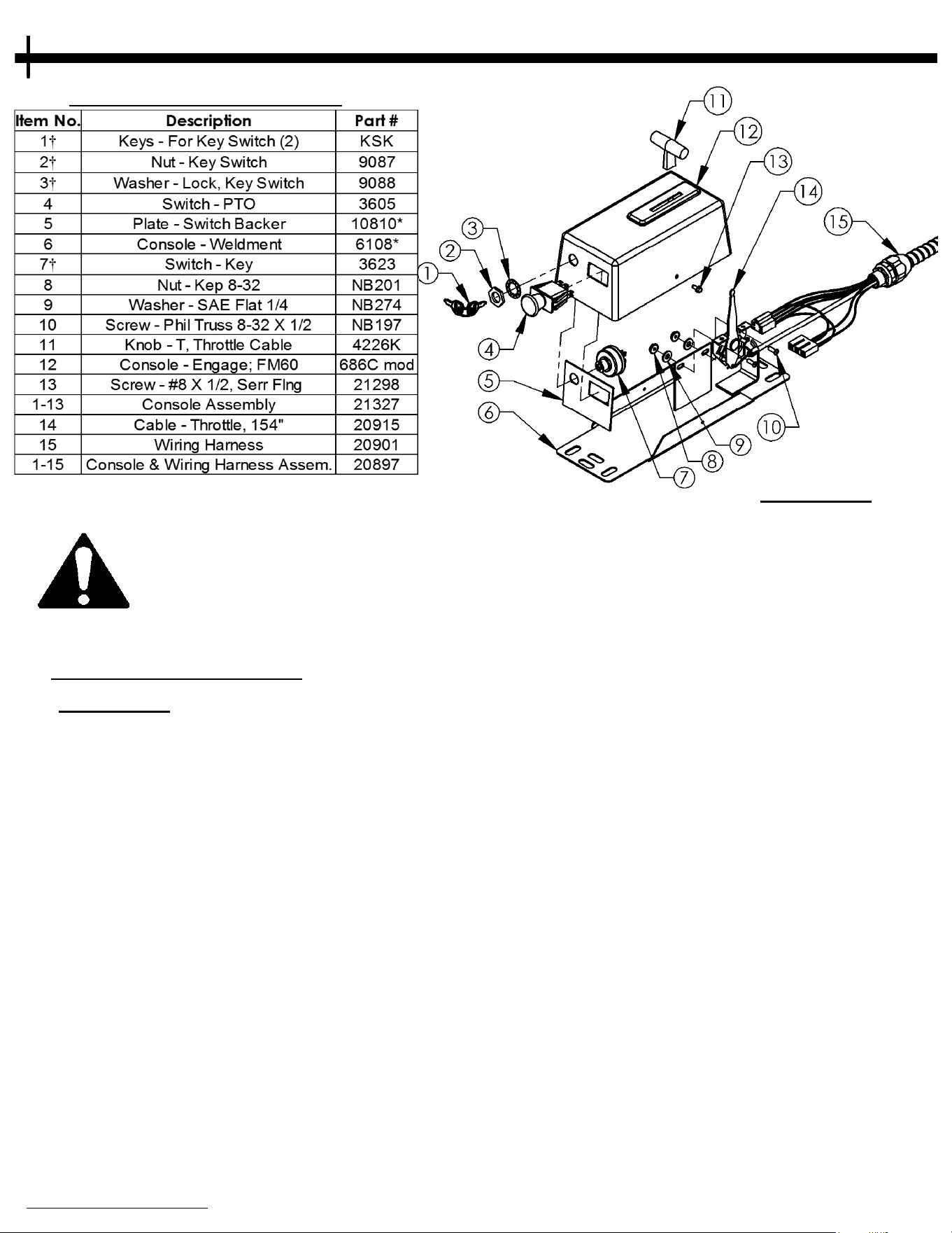
CONSOLE ASSEMBLY
FIGURE 29.1
When mounting the console assembly it may be necessary to mount it directly to the hitch tube
d
epending on the vehicle you are towing it with. Some vehicle configurations will allow the
console to be mounted to the vehicle (i.e. ATV rack). Make sure the wiring harness is secure
and will not drag the ground. Periodically check to make sure all hardware is tight and the
wiring harness is secure. NEVER operate this machine without the wiring harness being secure.
When ordering replacement parts
* = USE PAINT CODE: TK=BLACK
WIRING DIAGRAM
FIGURE 29.2
† Items 1, 2, 3 & 7 can be purchased as Key Switch Kit 21329.
N
ote: Some parts not shown for clarity.
PARTS DIAGRAMS
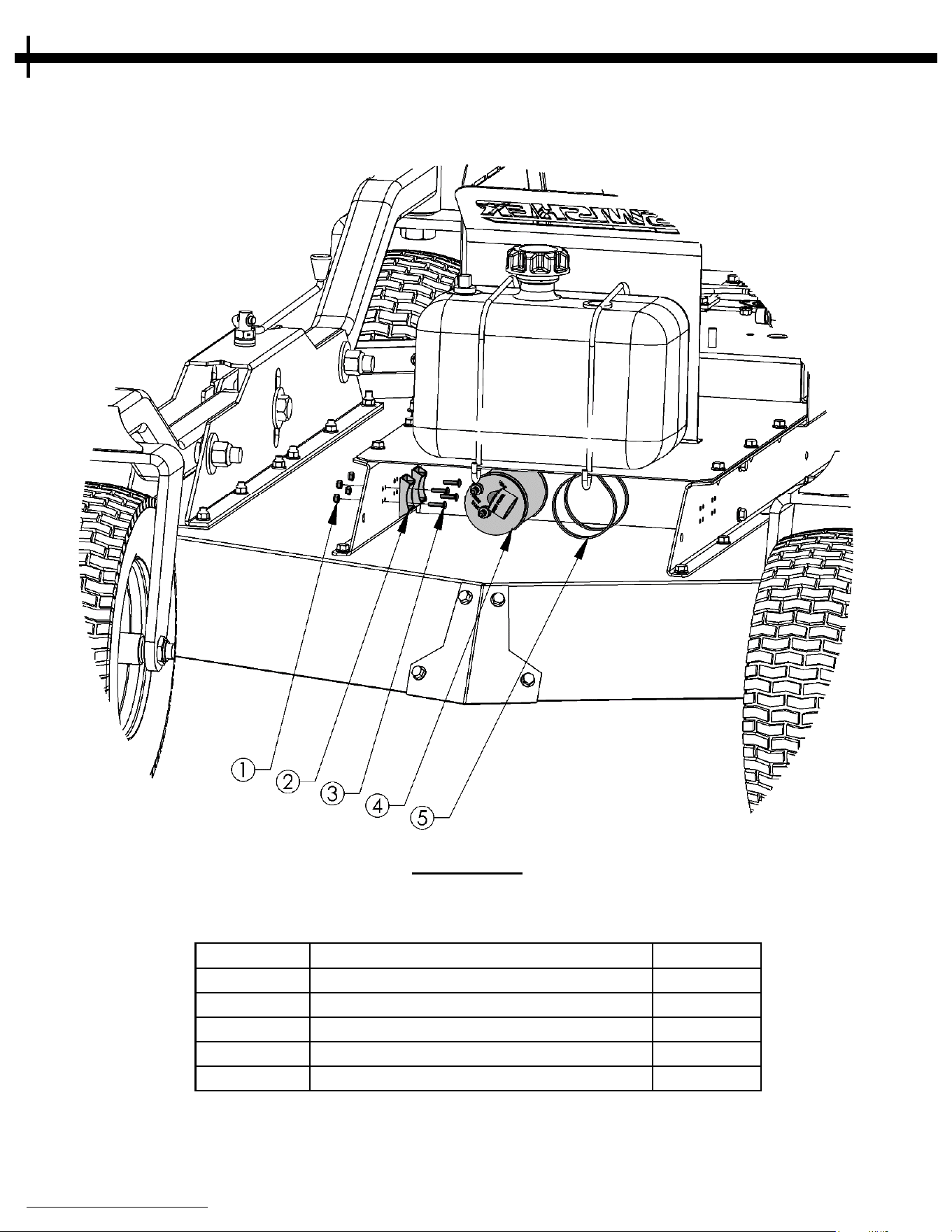
30
Item # Description Part #
1 Nut - 10-24 Nylon Lock 024900
2 Bracket - Carbon Canister 17127
3 Bolt - 10-24 X 3/4 024203
4 Carbon Canister - 2.50 Gallon 18224
5 Cable Tie - Carbon Canister 18219
When ordering replacement parts
* = USE PAINT CODE: TK=BLACK
California compliant Cutters are
equipped with a carbon canister.
FIGURE 30.1
CALIFORNIA EMISSIONS REQUIREMENTS

31

32
NOTES

鋠
Ң
33

44” BRUSH KING
T
RAIL CUTTER
Each Cutter has its own model number. Each engine has its
own model number. The model number for the Cutter will be
found on the right hand side of the motor mount. The model
number for the engine will be found on the top of the valve
cover.
All Cutter parts listed herein may be ordered directly from
Swisher or your nearest Swisher dealer.
All engine parts may be ordered from the nearest dealer of the
engine supplied with your Cutter.
WHEN ORDERING PARTS, PLEASE HAVE THE
FOLLOWING INFORMATION AVAILABLE:
* PRODUCT – RC44’’ BRUSH KING TRAIL CUTTER
* SERIAL NUMBER - _______________
* MODEL NUMBER - _______________
* ENGINE MODEL NUMBER - _______________
TYPE - _______________
* PART NUMBER
* PART DESCRIPTION
TELEPHONE - 1-800-222-8183
FAX - 1-660-747-8650
SWISHER ACQUISITION INC.
1602 CORPORATE DRIVE
WARRENSBURG, MO 64093
www.swisherinc.com
OWNER’S
M
ANUAL
www.swisherinc.com
CHANGING YOUR LANDSCAPE SINCE 1945
IMPORTANT
R
ead and follow all
Safety Precautions
and Instructions
before operating this
equipment.
MODEL NO.
RC
14544CP4K
RC14544CP4K-CA
34