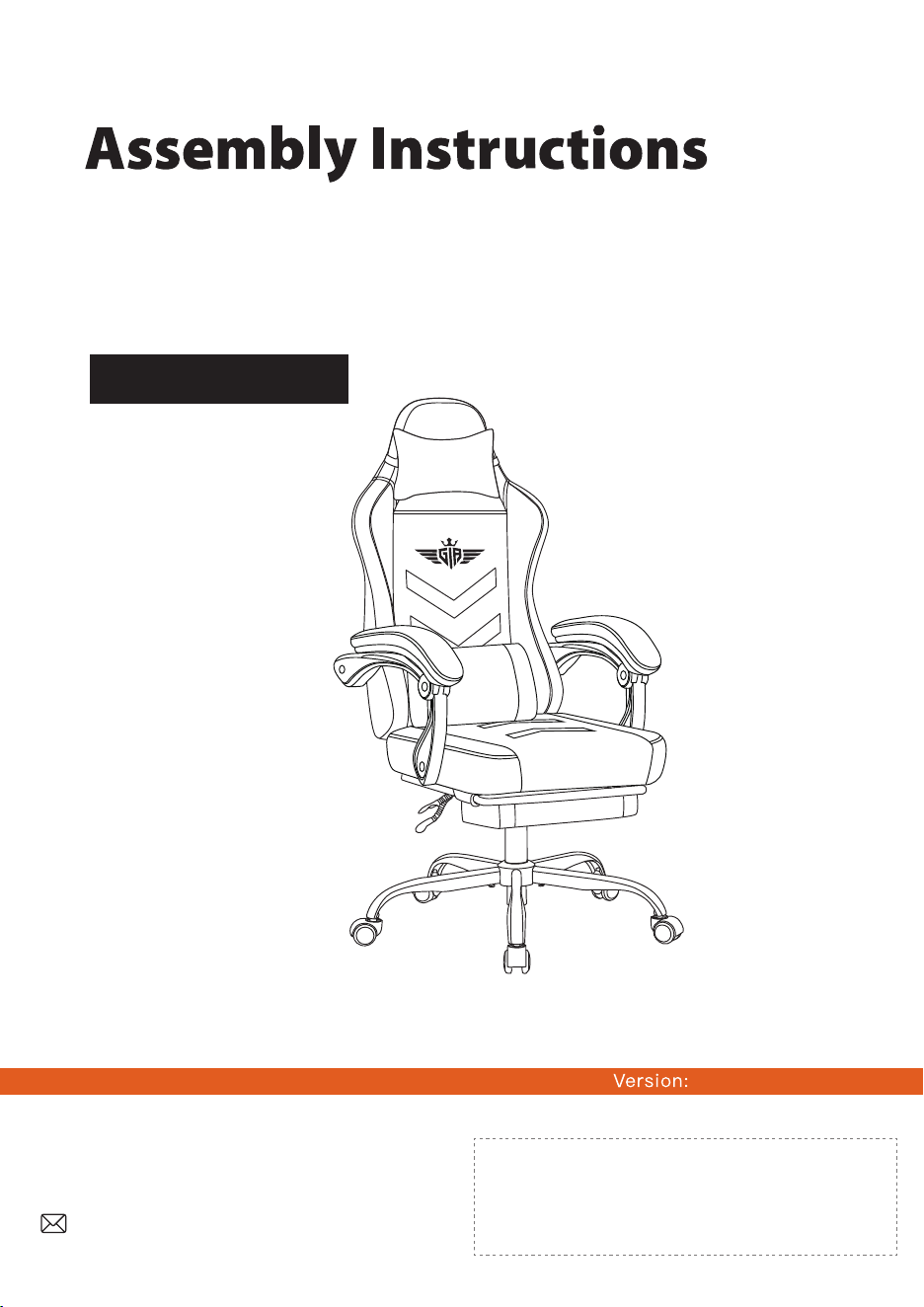
Model: XGC01-LT
2026.04.14.MC.H
This manual is intended for installation and use.
The pattern should be subject to the product you receive.
If you have any questions about the product,
please contact us through the contact information
on the left. We will strive to resolve your problem
within 24 hours on business days.
Customer Service Support
READ THIS MANUAL
Do not use this product until you read and understand
the instructions in this manual.
KEEP THIS MANUAL FOR FUTURE REFERENCE.
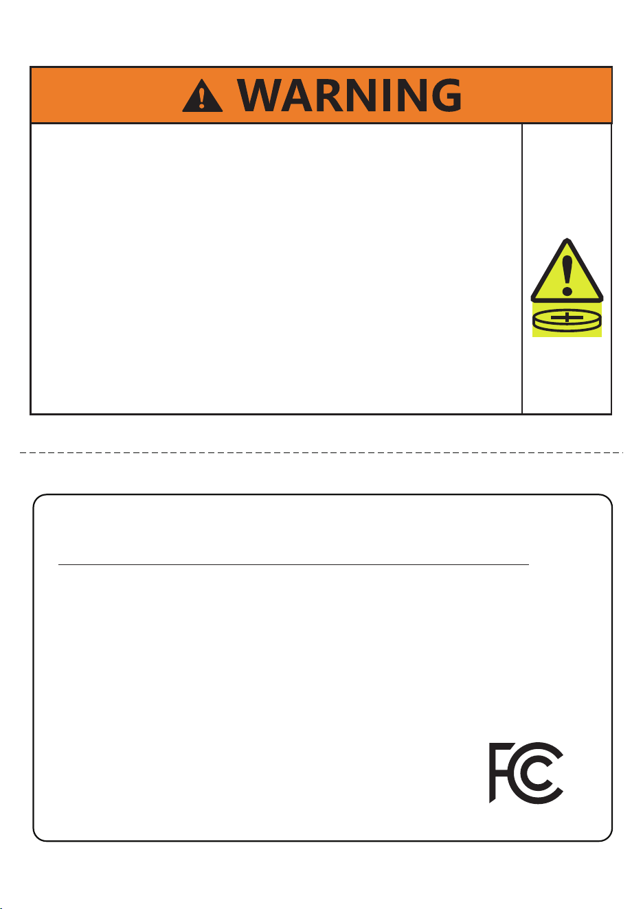
• INGESTION HAZARD:This product contains a
button cell or coin battery.
• DEATH or serious injury can occur if ingested.
• A swallowed button cell or coin battery can
cause INTERNAL CHEMICAL BURNS in as little
as 2 HOURS.
• KEEP new and used batteries OUT OF REACH
OF CHILDREN.
• SEEK IMMEDIATE MEDICAL ATTENTION if a
battery is suspected to be swallowed or inserted
inside any part of the body.
This device complies with Part 15 of the FCC Rules.
Operation is subject to the following two conditions:
(1) this device may not cause harmful interference, and
(2) this device must accept any interference received, including
interference that may cause undesired operation.
�
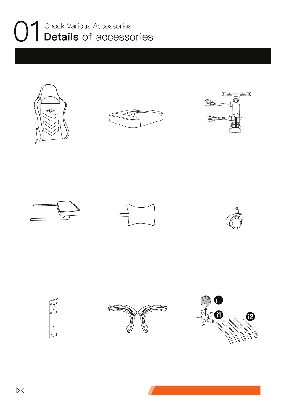
1. Main Parts
Please check and ensure all the things are in the package.
You can contact us for help if
something is not included.
Back Seat Mechanism
Footrest Headrest Caster
Connector Armrest Base
3
� � �
� � �
� � �
x1 x1 x1
x1x1 x5
x1 x1 setx1 set
Customer Service Support �
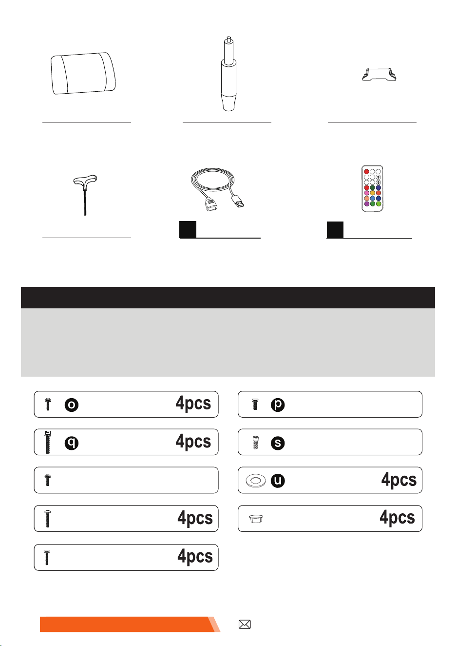
Lumbar Pillow Gas Lift Footrest Rail
� � �
x1x1 x2
2. Screws and Other Parts
◆ Please check and ensure all the things are in the package.
Please contact us if something is not included. We will reply
within 24 hours and try our best to solve it.
M8*40
�
5pcs
M6*20
CAP
�
3pcs
M8*20
1pc
M5*8
φ16*φ24*1.5mm
�
M6*30
M6*30
�
M6*22
Wrench
�
x1
x1
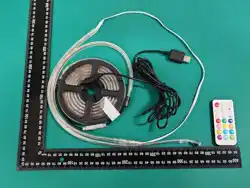
POWER CABLE
1
(The power cable is
2.5m long.)
RF REMOTE
x1
2
On
AUTO
Off
S+ M+
M-S-
Customer Service Support�
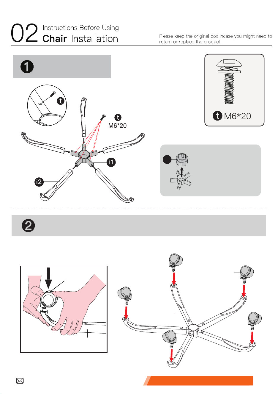
Install the base.
Please remove
the base cover.
i3
x5
Insert the casters.
�
�
�
�
Customer Service Support �
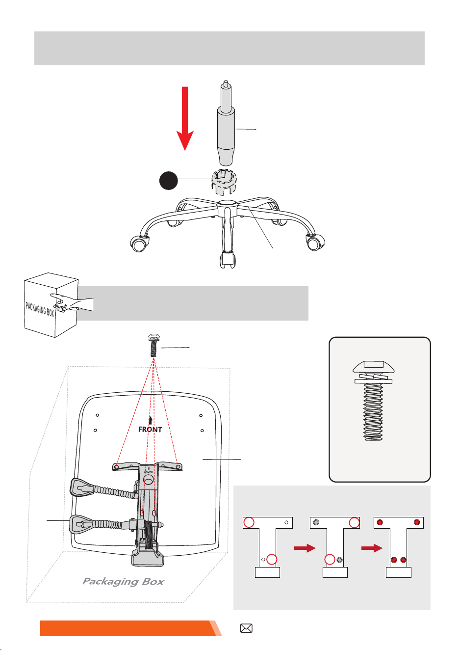
Install the mechanism.
➍
➌
Install the gas lift on the base.
�
�
i3
�
M6*22
�
�
M6*22
x4
�
MECHANISM ASSEMBLY ORDER
Install Screws
1 and 2
Install Screws
3 and 4
Tighten
all screws
1
�
2
�
3
4
�
Customer Service Support�
�
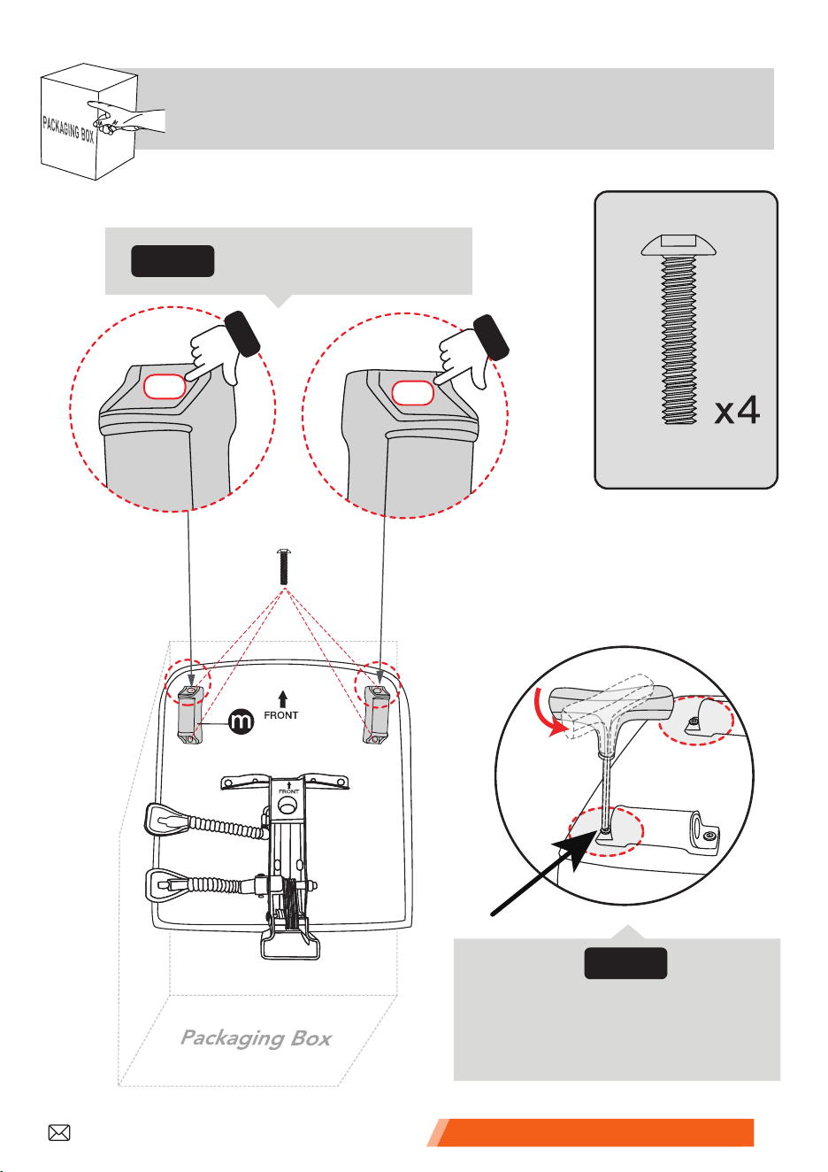
➎
(For easy installation, place the SEAT on top of the packaging box.)
Install the footrest rails.
Align the screw holes
horizontally.
Step1:
M6*30
M6*30
�
�
Tighten first, then loosen it
half a turn for smooth
footrest installation.
Step2:
Customer Service Support �
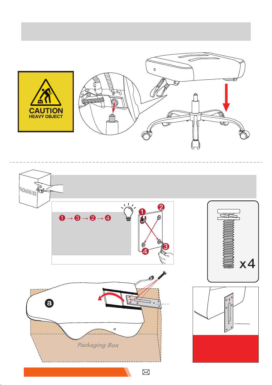
➏
Place the seat on the gas lift.
➐
(For easy installation, place the BACK on top of the packaging box.)
Install the connector on the chair back.
M6*30
�
*Payattentionto
thedirectionof
theconnector.
�
Tighten the screws in an
X-pattern for even
pressure, ensuring each
is fully tightened.
Handle with care!
M6*30
�
�
Customer Service Support�
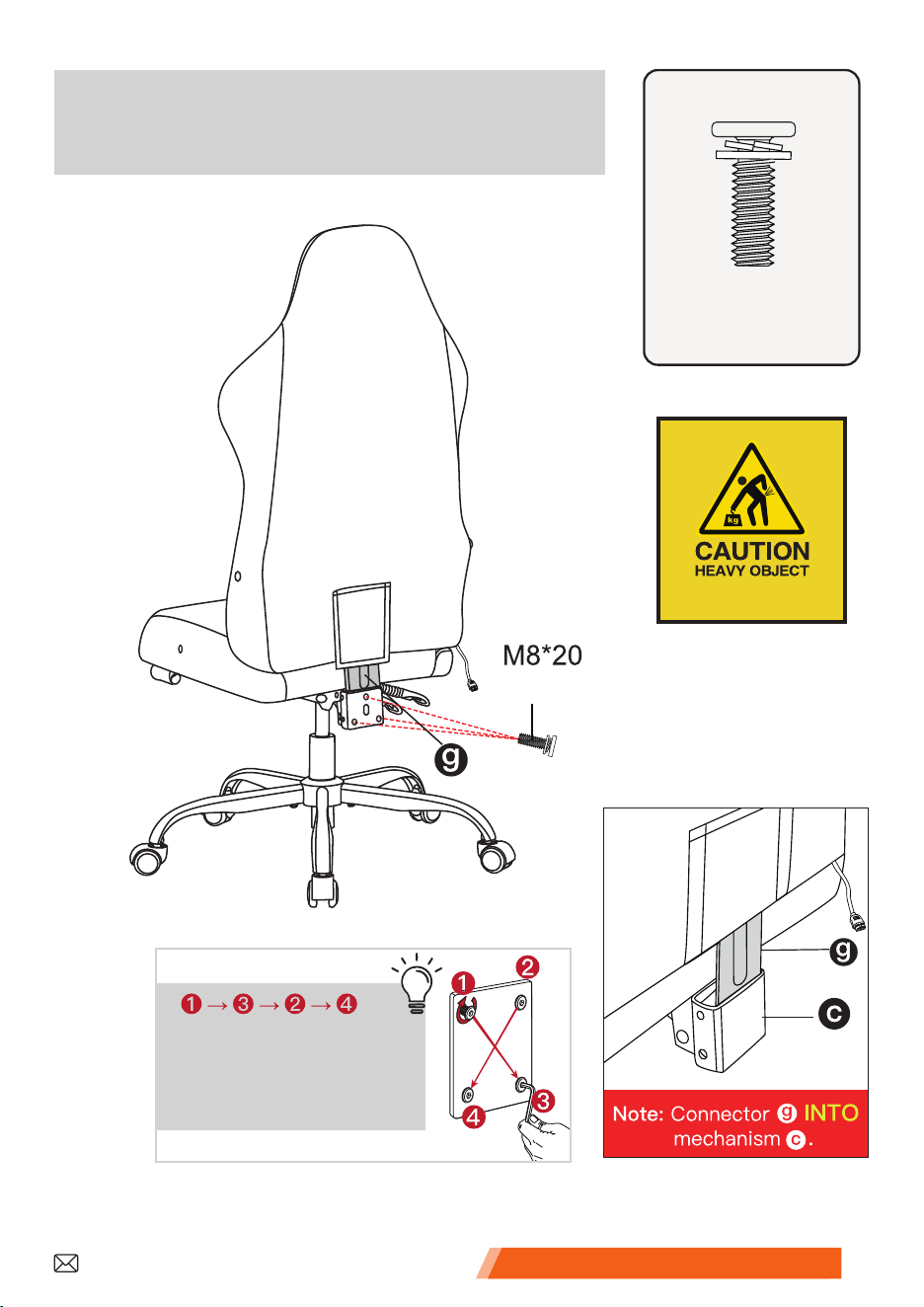
➑
Install the chair back on the rear
end of the mechanism.
M8*20
�
x3
Tighten the screws in an
X-pattern for even
pressure, ensuring each
is fully tightened.
Handle with care!
�
Customer Service Support �
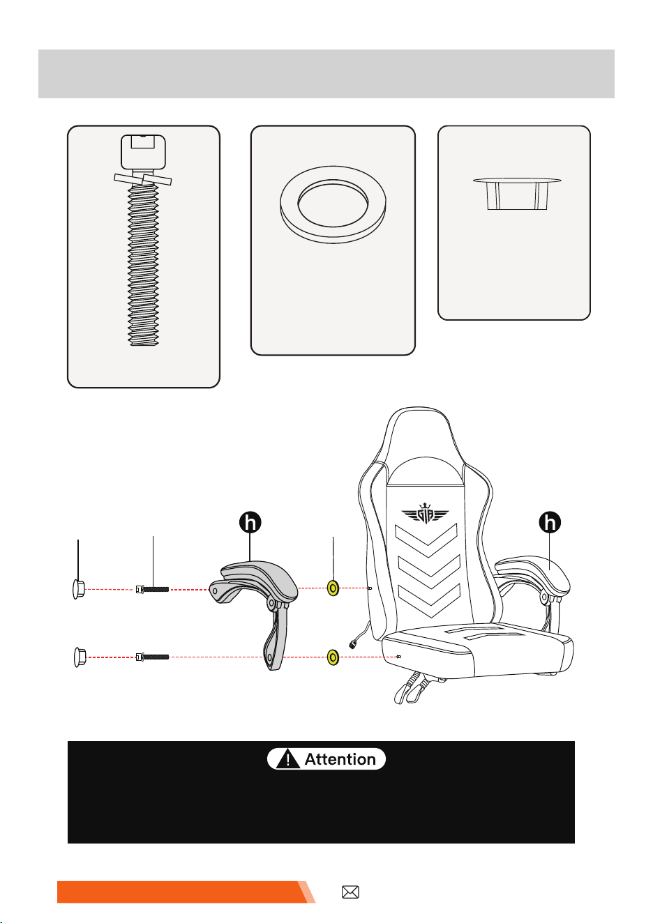
➒
Install the armrests.
1. Put the � between the armrest and chair body.
2. DO NOT tighten the screws completely until they are all
fixed in the correct position.
M8*40
�
�
�
�
M8
*
40
x4
CAP
�
x4
�
φ16*φ24*1.5
x4
Customer Service Support
�
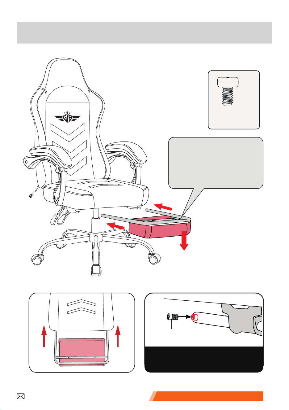
➓
Insert the footrest into the footrest rails.
M5*8
�
NOTE: Install the screw �
on one side ONLY.
�
x1
�
*Note: The footrest pedal
should be installed in a
downward direction (as
shown in the diagram).
Downward
M5*8
�
Customer Service Support �
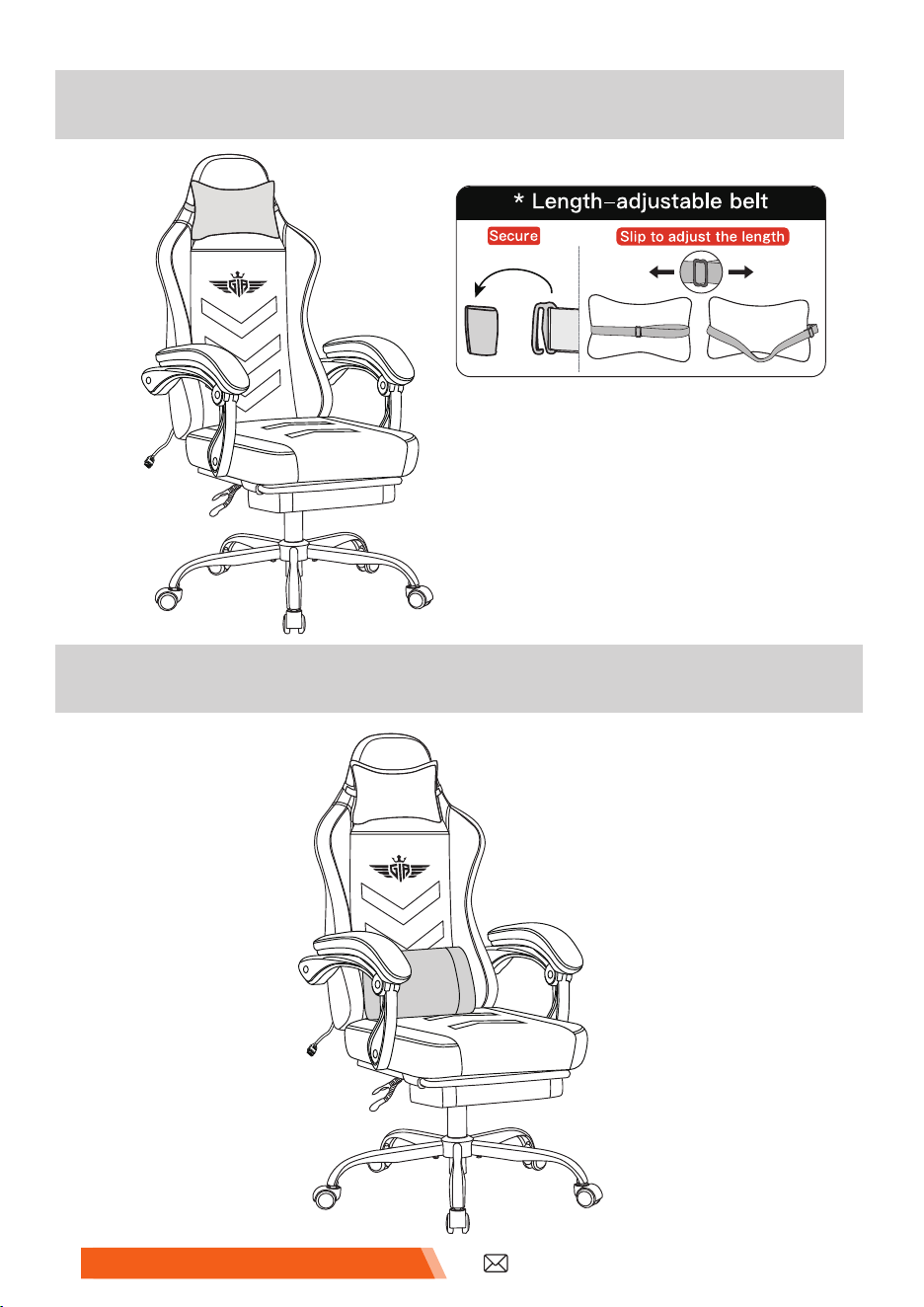
�
Insert the headrest.
�
Put on the lumbar pillow. Complete.
�
�
Customer Service Support�
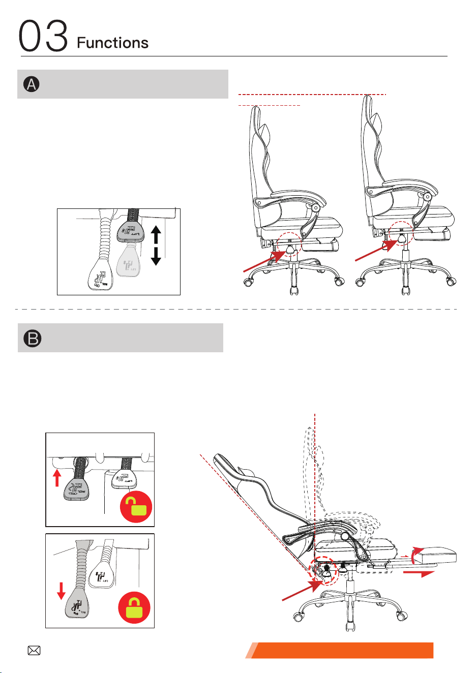
Back Recline Function
Lift up the “RCL” lever and the back angle tilts independently with user's
motion. Push down the “RCL” lever and the back angle is locked in position.
Rest on the back when resetting back to its normal position, otherwise
the back may rebound rapidly.
Lift up the “LIFT” lever to adjust
the height of chair, and release the
“LIFT" lever at a desired height.
Lift body slightly off the seat when
adjusting the height.
Chair Height Adjustment
Please read the function introduction carefully.
Instructions For Use
Display
Customer Service Support �
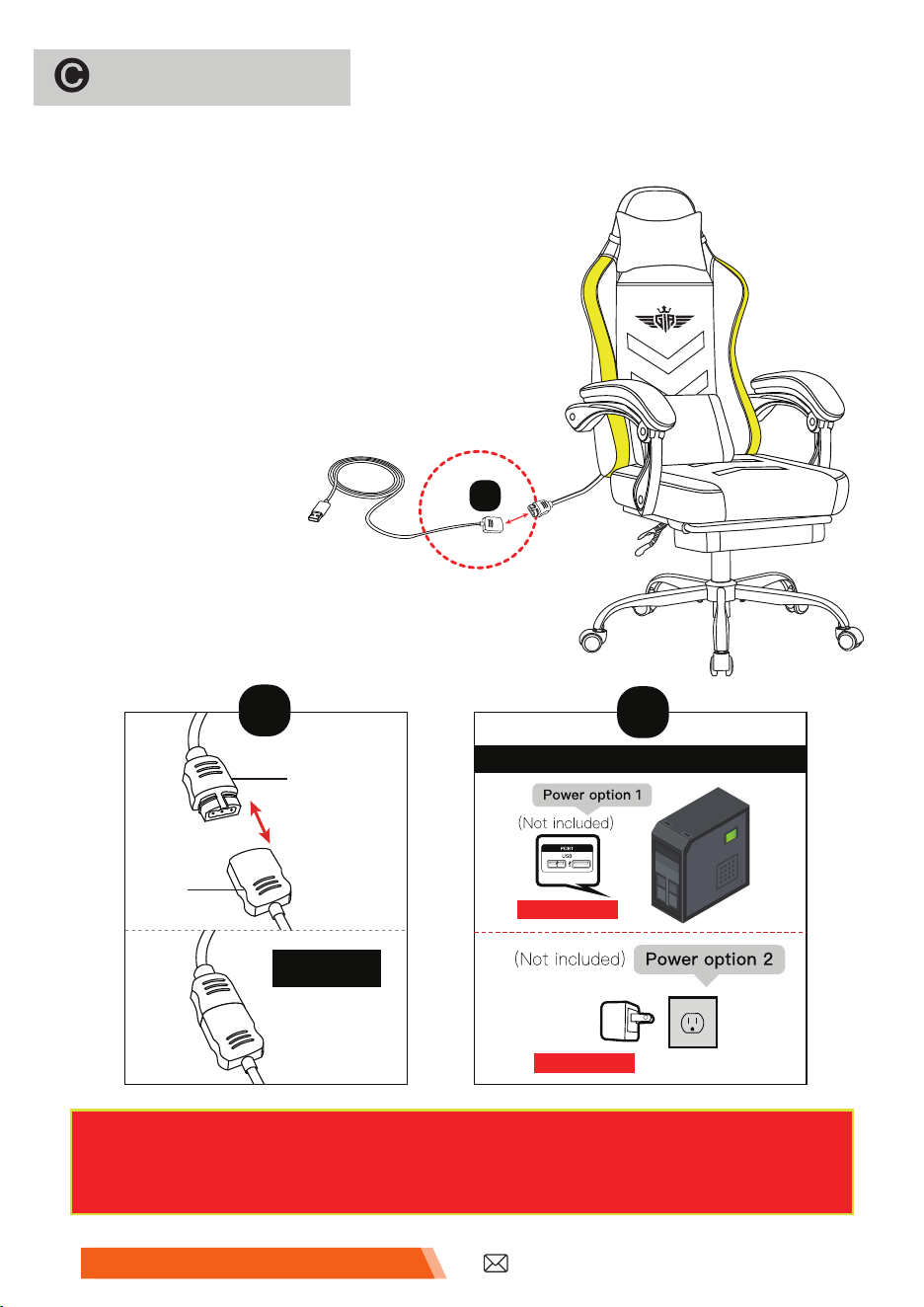
Ambient light
◆ Connect the light unit cables.
�
01
01
02
Back
Insert
Power Option
5V/0.5-2A
5V/0.5-2A
� Power
◆ Connect the light unit cables. Long press any key on
the RF Remote control (except the power button) for
3-5 seconds to successfully pair.
◆ Plug into the socket. Use the RF Remote to
operate the lights.
◆ The power input is USB 5V/0.5-2A and the
wireless control distance is 59ft (No occlusion).
�
NOTE: Voltage exceeding 5V/3A will cause a short circuit on the
product's chip board. Please check the voltage parameters
before use.
Customer Service Support
�
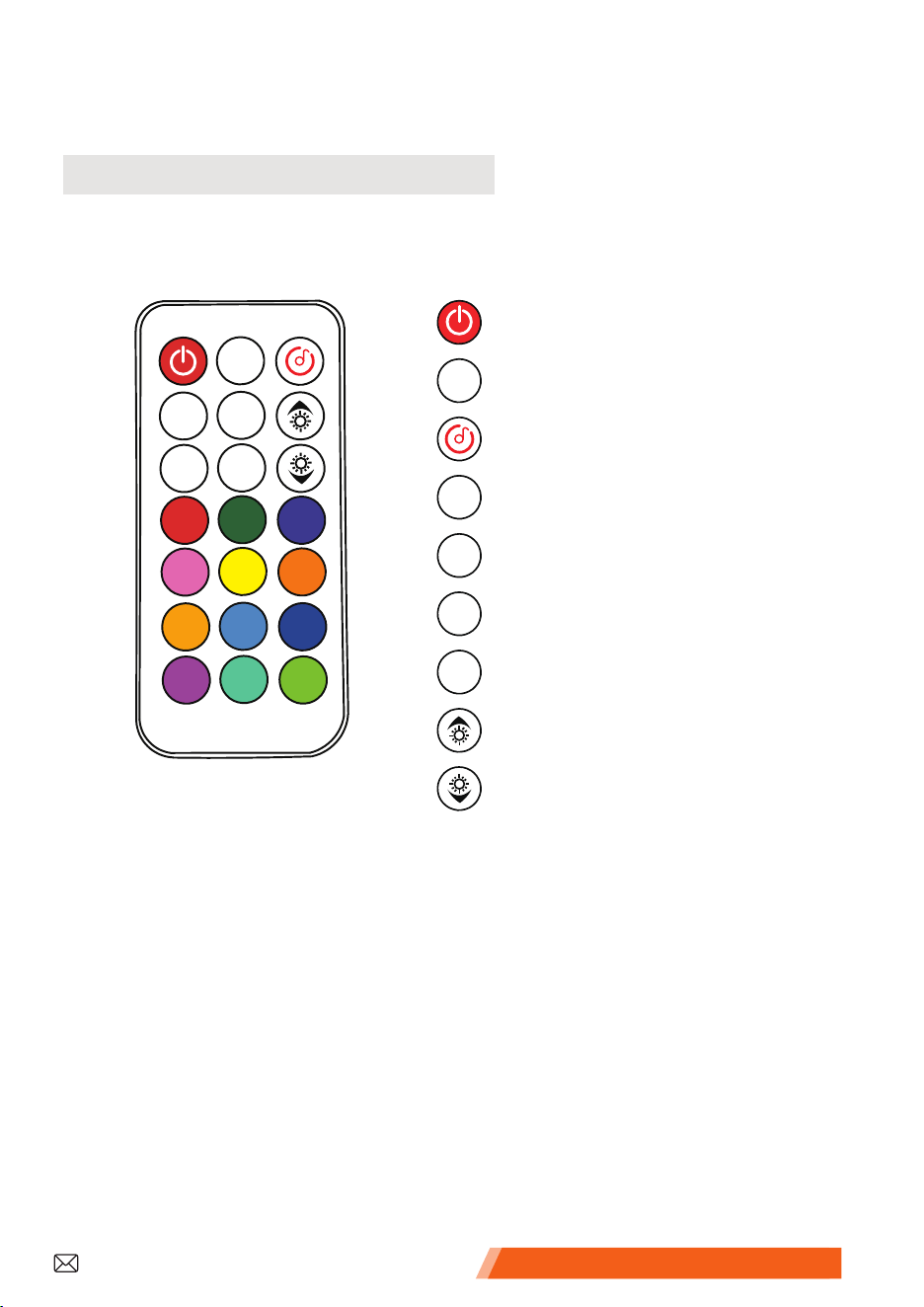
� RF Remote Control Manual
LED Color Buttons(12 Colors)
Dynamic lighting will perfectly customise different styles of scene
effects for you.
Dynamic Mode
Static Red / Static Green / Static Blue / Static Pink / Static Yellow
/ Static Orange / Static Light Orange / Static Light Blue / Static
Dark Blue / Static Purple / Static Onion green / Static Grass Green
�
AUTO
S+
M+
M-
S-
RF Remote
Turn on/off
Auto Mode
Flash Effect
Flashing Speed +
Flashing Speed -
Dynamic Mode UP
Dynamic Mode DOWN
Brightness +
Brightness -
AUTO
S+ M+
M-S-
2.1 RF Remote Control Manual
Customer Service Support �

* Remove the plastic card before
powering on the chair.
AUTO
S+ M+
M-S-
2.3 Light Strip Bluetooth Control App
Repower the light strip, hold any button for about 3 seconds.
When it flashes, you can operate it with the RF remote.
2.2 RF Remote Pairing
Or you can also just search
Γ
Lynck
┛
in your phone’s app store to
download the app.
Download the
Γ
Lynck
┛
App
iPhone
Download for
Android
Download for
Customer Service Support
�
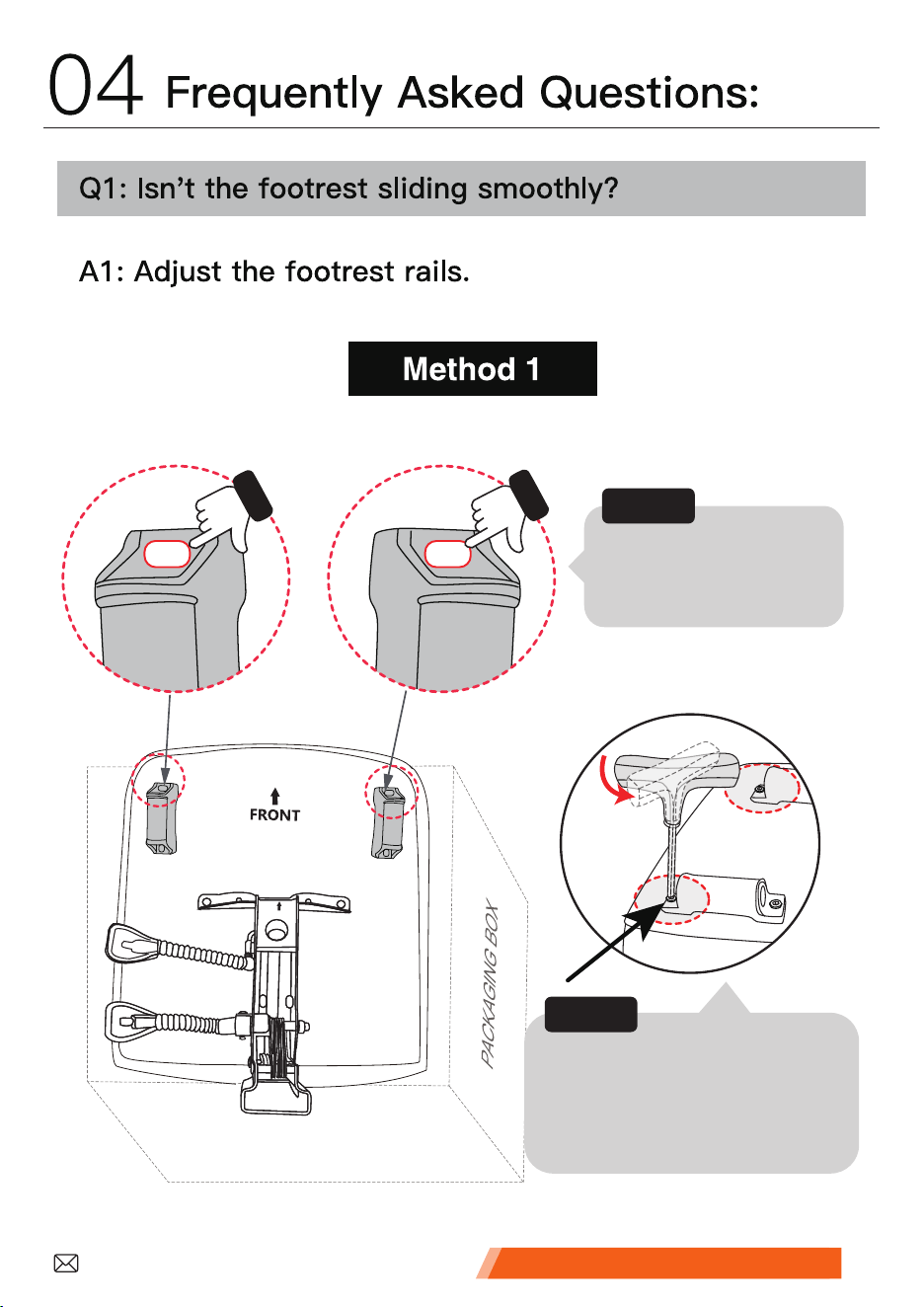
Align the screw
holes horizontally.
FRONT
Tighten first, then loosen
it half a turn for smooth
footrest installation.
Step1:
Step2:
Customer Service Support �
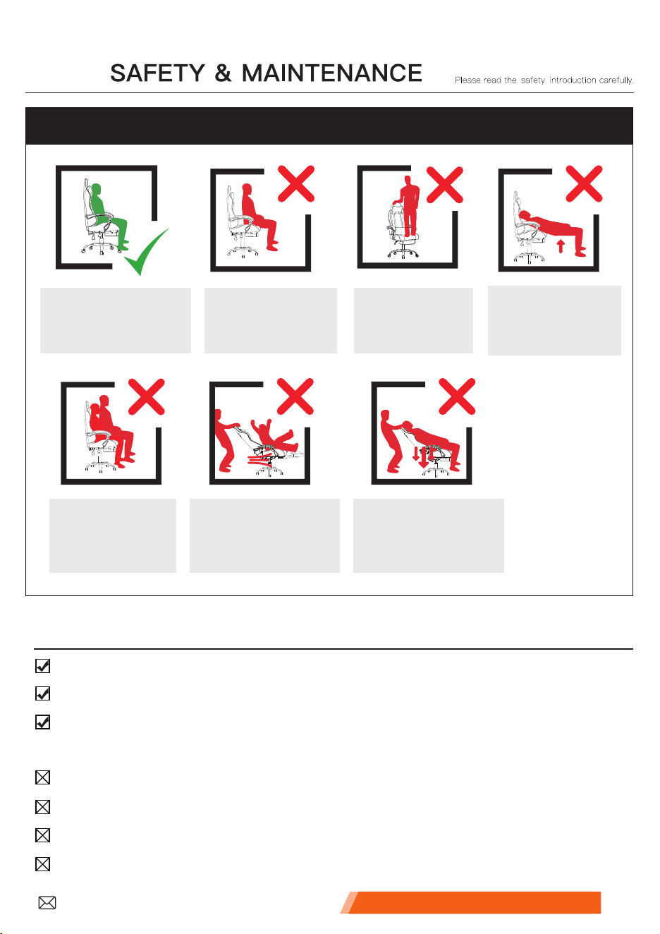
DONOTplaceonly
yourbackon
thechair
DONOTpushdown
onthebackrestwhen
apersonisreclined
DONOTturnthechair
aroundwhenaperson
issittinginit.
Sitinthecenterof
thechairwithyour
backtothebackrest.
DONOTsitat
thefrontedgeof
thechair.
DONOTstand
onthechair.
DONOTusethe
chairwithmore
thanoneperson.
Please use the chair properly to prevent any potential safety accidents.
SAFETY INFORMATION
05
Use this chair for seating only one person at a time.
Every 6 months, check all screws to ensure they are all tight.
To clean, use a damp towel and mild cleaner. First, test on a small,
hidden area of fabric.
DO NOT stand on the chair.
DO NOT use the chair as a stepladder.
DO NOT use the chair unless all screws are firmly secured.
DO NOT contact with sharp objects to prevent puncturing the fabric.
Customer Service Support �
Dear Customer,
Thank you for choosing us.
For safe use, please read this manual before installation and keep it for future reference.
If you have any questions about the product, please feel free to contact us via email. We
will reply within 24 hours.
To help us assist you effectively in case you encounter any issues during installation or
usage, please note the following:
• If the product is damaged due to courier handling, please contact our customer service
promptly for verification.
• We will address the issue as quickly as possible.
• A 1-year quality assurance is provided.
We provide detailed product information, installation instructions, and guidance on care
and maintenance.
If you are satisfied with our product and service:
• Please add our store to your favorites;
• Recommend our products to your friends;
• Share your shopping experience in our store or on the product page.
Your feedback and reviews help us continually improve and offer better service to
customers worldwide.
Best regards!
1
If you have any questions about the product,
please contact us through the contact information
on the left. We will strive to resolve your problem
within 24 hours on business days.
Customer Service Support

This device complies with part 15 of the FCC Rules. Operation is subject to the
following two conditions: (1) This device may not cause harmful interference, and (2)
this device must accept any interference received, including interference that may cause
undesired operation.
Any Changes or modifications not expressly approved by the party responsible for
compliance could void the user's authority to operate the equipment.
Note: This equipment has been tested and found to comply with the limits for a Class B
digital device, pursuant to part 15 of the FCC Rules. These limits are designed to
provide reasonable protection against harmful interference in a residential installation.
This equipment generates uses and can radiate radio frequency energy and, if not
installed and used in accordance with the instructions, may cause harmful interference
to radio communications. However, there is no guarantee that interference will not
occur in a particular installation. If this equipment does cause harmful interference to
radio or television reception, which can be determined by turning the equipment off and
on, the user is encouraged to try to correct the interference by one or more of the
following measures:
-Reorient or relocate the receiving antenna.
-Increase the separation between the equipment and receiver.
-Connect the equipment into an outlet on a circuit different from that to which the
receiver is connected.
-Consult the dealer or an experienced radio/TV technician for help.
FCC Radiation Exposure statement
The device has been evaluatec to meel general RF exposure requirement. The device
can be used in portable exposure condition without restriction.

