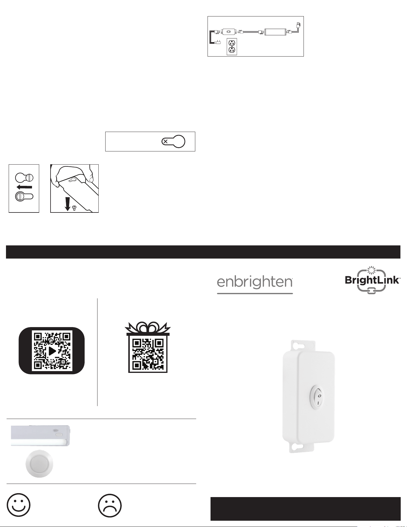
Thank you for your purchase!
Instructions
made easy
Exclusive deals
Read instructions or
watch easy-to-follow
video. Scan code or visit
byjasco.com/45087i
For deals, to register your
purchase and to tell us how
we’re doing, simply scan
the code or visit
byjasco.com/deals
Having problems?
Let us know how we can
help. Call 1-800-654-8483
between 7AM-8PM, M-F,
Central Time.
Like our product?
Leave a review on your
favorite retailer website
or amazon.com
INSTALLATION INSTALLATION
SAVE THESE INSTRUCTIONS FOR
POSSIBLE FUTURE USE.
Thank you for purchasing the
BrightLink™ ON/OFF Switch. Please
note that this product is intended for
use ONLY with lighting fixtures that
are specifically compatible with the
BrightLink linking system.
IMPORTANT SAFETY INSTRUCTIONS
Read entire installation procedure
before you begin. Do not alter the
connectors.
Electrical Ratings: On/O Module
Line Voltage 120V
Maximum Current 10A
Maximum Wattage 1200W
DO NOT exceed maximum electrical
ratings listed above. To make sure
your installation will not exceed
ratings, add the current (A) or
wattage (W) rating for all light
fixtures that will be connected to the
switch. The total sum of the current
or wattage for all connected light
fixtures cannot exceed the maximum
listed above for the type of module
being installed.
INSTALLATION INSTRUCTIONS
FOR ON/OFF SWITCH
The ON/OFF Switch is intended
for use with the BrightLink linking
system to allow you to control
power to a connected series of
compatible lighting fixtures. The
entire connected series of lights can
be turned ON/OFF with a single
module instead of turning ON/OFF
each individual light fixture.
DO NOT ATTEMPT TO INSTALL
SWITCH WHILE PLUGGED IN OR
WITH PLUGGED-IN LIGHTING
FIXTURES.
Step 1: If installing the switch within
a previously installed light fixture
installation using the BrightLink
linking system, unplug the power
supply cord from the 120VAC 60Hz
outlet and disconnect the 3-pin
connector from the first LED light
fixture.
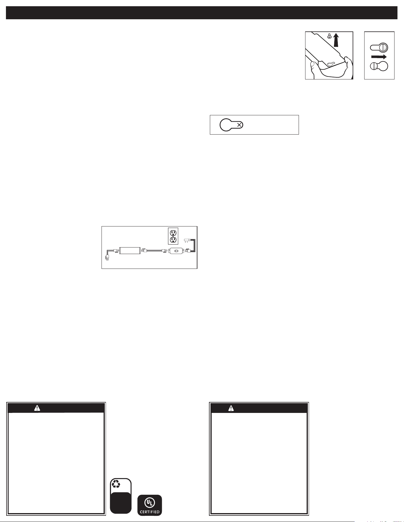
Step 2: Carefully plan your
installation prior to mounting the
switch. See Figure 1 for layout
of components and all electrical
connections. Make sure that the 5ft.
power supply cord will reach the
nearest electrical outlet and
the switch location, and that the
linking cord will reach the first
LED light fixture.
Step 3: Select a suitable dry
mounting location (for use indoors
only). Make sure mounting surface
is capable of supporting the switch.
Step 4: Place the switch in the
desired location and clearly mark
the locations for the two mounting
holes. See Figure 2. Make sure
the 2-pin connector is facing the
direction of the first light fixture
and the 3-pin connector is facing
the direction of the closest
electrical outlet.
Step 5: Pre-drill holes in the
mounting surface with a 1/16in.
(1.5mm) drill bit.
Step 6: Place the provided 5/8in.
wood screws in the pre-drilled
mounting holes and drive the screws
into the mounting surface until
approximately 1/16in. (1.5mm) of
space remains under the screw head.
Use only a #1 Phillips head manual
screwdriver to avoid stripping
screws.
CAUTION:DO NOT USE POWER
TOOLS TO SECURE SCREWS, AS
THERE IS A RISK OF
STRIPPING THE SCREWS.
Step 7: Secure the switch to
mounting surface via keyholes.
See Figure 3 and Figure 4. If
necessary, tighten screws to
secure switch.
Step 7: Connect the linking cord
(provided with compatible light
fixture). Insert the 2-pin connector
of the linking cord into the 2-pin
connector on the switch. Insert the
3-pin connector of the linking cord
into the 3-pin connector of the first
light fixture.
Step 8: Insert the 3-pin connector of
the power supply cord into the 3-pin
connector on the switch.
Step 9: Plug the power supply cord
plug into a 120VAC 60Hz outlet.
Step 10: Ensure the power switch
to all individually connected light
fixtures is turned ON.
Step 11: The BrightLink ON/OFF
switch will now turn ON or OFF
the entire system of connected
light fixtures.
ON/OFF Switch
User Manual
See reverse for easy-to-follow
instructions and exclusive deals.
IMPORTANT: BEFORE INSTALLING, READ ALL SAFETY
INSTRUCTIONS LISTED AT THE END OF THIS MANUAL.
Discover more premium LED
lighting and lighting accessories
at enbrightenme.com
1 /16in (1.5mm)
from the end
Insert
Slide
BrightLink™
ON/OFF Switch
LED Light
Fixture
3 Pin
ELECTRICAL CORD CAN BE
ROUTED AROUND CORNERS
TO SUIT THE INSTALLATION
2 Pin 2 Pin3 Pin
3 Pin
Figure 1
Figure 2
Figure 3 Figure 4
MADE IN THAILAND
Distributed by Jasco Products Company LLC,
10 E. Memorial Rd., Oklahoma City, OK 73114.
This Jasco product comes with a limited-lifetime
warranty. Visit www.byjasco.com for
warranty details.
Questions? Contact our U.S.-based Consumer
Care at 1-800-654-8483 between 7AM-8PM,
M-F, Central Time.
HECHO EN THAILAND
Distribuido por Jasco Products
Company LLC, 10 E Memorial Rd.,
Oklahoma City, Oklahoma 73114.
Este producto de Jasco tiene una
garantía de por vida limitada. Visite
www.byjasco.com para conocer los
detalles de la garantía.
¿Preguntas? Comuníquese al
1-800-654-8483 entre las 7AM y las
8PM CST(hora central estándar).
45087 v2 10/21
UCM/1/40/120
RISK OF ELECTRIC SHOCK
• DO NOT USE IN WET LOCATIONS.
• USE INDOORS ONLY.
• USE ONLY INSULATED STAPLES OR PLASTIC TIES TO
SECURE THE CORDS.
• ROUTE AND SECURE THE CORDS SO THAT THEY
WILL NOT BE PINCHED OR DAMAGED.
• NO SERVICEABLE PARTS
RISK OF FIRE
• DO NOT EXCEED ELECTRICAL RATINGS
• USE ONLY WITH BRIGHTLINK-COMPATIBLE
LIGHTING FIXTURES.
• NOT INTENDED FOR USE ABOVE STOVES, COOK
TOPS, SINKS OR OTHER HEAT PRODUCING
APPLIANCES, SUCH AS COFFEE MAKERS, TOASTERS
OR TOASTER OVENS.
• NOT INTENDED FOR RECESSED INSTALLATION IN
CEILINGS OR SOFFITS.
• DO NOT CONCEAL POWER SUPPLY CORD OR
LINKING CORDS INSIDE A WALL, CEILING, SOFFIT,
KITCHEN CABINET OR SIMILAR PERMANENT
STRUCTURE.
• DO NOT RUN POWER SUPPLY CORD OR LINKING
CORDS THROUGH HOLES IN WALLS, CEILINGS
OR FLOORS.
RIESGO DE DESCARGA ELÉCTRICA
• NO UTILICE EN LUGARES HÚMEDOS.
• SOLO PARA USO EN INTERIORES.
• PARA FIJAR LOS CABLES, SOLO USE GRAPAS
AISLADAS O PRECINTOS DE PLÁSTICO.
• PASE Y FIJE LOS CABLES DE MODO QUE NO
QUEDEN APRETADOS NI SE DAÑEN.
• NO TIENE PIEZAS QUE EL USUARIO PUEDA
REPARAR.
RIESGO DE INCENDIO
• NO SUPERE LOS VALORES NOMINALES
ELÉCTRICOS.
• SOLO USE CON ARTEFACTOS DE ILUMINACIÓN
COMPATIBLES CON BRIGHTLINK.
• NO SE DEBE USAR SOBRE HORNILLOS, PLACAS
DE COCINA, FREGADEROS NI NINGÚN OTRO
DISPOSITIVO QUE GENERE CALOR, COMO
CAFETERAS, TOSTADORAS NI HORNOS
ELÉCTRICOS.
• ESTA UNIDAD NO ESTÁ DISEÑADA PARA MONTAJE
EMPOTRADO AL TECHO O EN UN SOFITO.
• NO OCULTE EL CABLE DE ALIMENTACIÓN
ELÉCTRICA O LOS CABLES DE CONEXIÓN DENTRO
DE UNA PARED, EL CIELO RASO, UN SOFITO, UN
MUEBLE DE COCINA O UNA ESTRUCTURA SIMILAR
QUE SEA PERMANENTE.
• NO PASE EL CABLE DE ALIMENTACIÓN ELÉCTRICA
NI LOS CABLES DE CONEXIÓN POR ORIFICIOS EN
PAREDES, EL CIELO RASO O EL SUELO.
WARNING
ADVERTENCIA
INSTALACIÓN INSTALACIÓN
Descriptor/
Descriptor:
100%
recyclable
Separate
label from
package
before
recycling
byjasco.com/recycle
GUARDE ESTAS INSTRUCCIONES
PARA UN POSIBLE USO EN EL
FUTURO.
Gracias por adquirir el módulo
de Encendido/Apagado
(On/O) BrightLink™. Tenga en cuenta
que este producto está diseñado
para usarse SOLO con artefactos de
iluminación que sean específicamente
compatibles con el sistema de
conexión BrightLink.
INSTRUCCIONES DE SEGURIDAD
IMPORTANTES
Antes de comenzar, lea todo el
procedimiento de instalación. No
modifique los conectores.
Especificaciones eléctricas:
Módulo de Encendido/Apagado
(On/O)
Voltaje de línea 120V
Corriente máxima 10A
Máxima potencia 1200W
NO supere los valores nominales
eléctricos estipulados arriba. Para
asegurarse de que su instalación
no superará los valores nominales
eléctricos, sume la corriente (A) o la
potencia (W) de todos los artefactos
de iluminación que se conectarán al
módulo. La suma total de la corriente
o la potencia de todos los artefactos
de iluminación conectados no puede
superar el máximo estipulado arriba
para el tipo de módulo a instalar.
INSTRUCCIONES DE INSTALACIÓN
PARA EL MÓDULO DE ENCENDIDO/
APAGADO
El módulo de ENCENDIDO/APAGADO
está diseñado para usarse con el
sistema de conexión BrightLink que
le permitirá controlar la alimentación
de series conectadas de artefactos
de iluminación compatibles. Todas las
series de luces conectadas pueden
ENCENDERSE/APAGARSE con un
solo módulo en lugar de ENCENDER/
APAGAR cada artefacto de iluminación
individual.
NO INTENTE INSTALAR EL MÓDULO
MIENTRAS ESTÁ ENCHUFADO O
CON ARTEFACTOS DE ILUMINACIÓN
ENCHUFADOS.
PASO 1 De instalar el módulo en
una instalación de artefactos de
iluminación ya instalados usando
el sistema de conexión BrightLink,
desenchufe el cable de alimentación
del tomacorriente de 120VCA 60Hz y
desconecte el conector de 3 clavijas
del primer artefacto de
luz LED.
PASO 2 Planifique detenidamente
la instalación antes de montar el
módulo. Consulte la Figura 1 para ver
la distribución de los componentes
y de todas las conexiones eléctricas.
Asegúrese de que el cable de
alimentación de 5 pies (152 cm) llegue
al tomacorriente más cercano y a la
ubicación del módulo y de que el cable
de conexión llegue al primer artefacto
de luz LED.
PASO 3 Seleccione un lugar seco
adecuado para la instalación (solo para
uso en interiores). Asegúrese de que la
superficie de instalación sea capaz de
mantener el módulo.
PASO 4 Coloque el módulo en la
ubicación deseada y marque, de
forma clara, las ubicaciones de los dos
orificios de instalación. Ver Figura 2.
Asegúrese de que el conector de 2
clavijas esté orientado hacia el primer
artefacto de iluminación y de que el
conector de 3 clavijas esté orientado
hacia el tomacorriente más cercano.
PASO 5 Perfore los orificios en la
superficie de instalación con una
broca de 1/16in (1,5 mm).
PASO 6 Ubique los tornillos para
madera de 5/8in provistos en los
orificios de instalación ya perforados
y atorníllelos en la superficie de
montaje hasta que quede un espacio
aproximado de 1/16in (1,5 mm)
debajo de la cabeza del tornillo. Solo
puede usar un destornillador manual
Phillips número 1 para evitar barrer
los tornillos. PRECAUCIÓN: NO USE
HERRAMIENTAS ELÉCTRICAS PARA
FIJAR LOS TORNILLOS, YA QUE
EXISTE EL RIESGO DE BARRERLOS.
PASO 7 Asegure el módulo en la
superficie de instalación por medio de
los orificios. Ver Figura 3 y Figura 4. De
ser necesario, ajuste los tornillos para
asegurar el módulo.
PASO 8 Conecte el cable de conexión
(provisto con el artefacto de
iluminación compatible). Inserte el
conector de 2 clavijas del cable de
conexión en el conector de 2 clavijas
del módulo. Inserte el conector de
3 clavijas del cable de conexión en
el conector de 3 clavijas del primer
artefacto de iluminación.
PASO 9 Inserte el conector de 3
clavijas del cable de alimentación en
el conector de 3 clavijas del módulo.
PASO 10 Enchufe el cable de
alimentación en un tomacorriente de
120VCA 60Hz.
PASO 11 Asegúrese de que el
interruptor de alimentación para
cada uno de los artefactos de
iluminación conectados esté
ENCENDIDO.
PASO 12 El interruptor de
ENCENDIDO/APAGADO del módulo
de ENCENDIDO/APAGADO ahora
ENCENDERÁ o APAGARÁ todo el
sistema de artefactos de iluminación
conectados.
1 /16in (1.5mm)
desde el borde
Figura 2
Figura 3 Figura 4
Inserte
Deslice
EL CABLE ELECTRICO PODRA
SER COLOCADO ALREDEDOR DE
ESQUINAS PARA ACOMADARSE A
SU INSTALACION
2 Postes 2 Postes3 Postes
3 Postes
Figura 1
´ ´
´
3 Postes
Modulo de
Encendido/Apagado
(ON/OFF) BrightLink