ENEN
User’s manual
ZONA PER
TARGHETTA
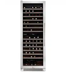
COLUMN
WINE COOLER
USER
MANUAL
MODEL
UWFC18
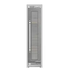
- 18" Wine Column
UWFC24 - 24" Wine Column
EN
1 646-444-8054 | [email protected] | US.ILVE.COM | ©ILVE USA 2026. ALL RIGHTS RESERVED.
Use, Care, and Installation Guide
2
Page
Safety Information......................................................................................3-10
Types of Safety Warnings................................................................................ 3
General Safety............................................................................................... 4-6
Save These Instructions................................................................................. ..7
Disposal of Old Appliance...............................................................................7
Before Using Your Appliance.......................................................................... 8
Installation of Your Appliance......................................................................8-9
Attention............................................................................................................9
Electrical Connection...................................................................................... 10
Introduction......................................................................................................12
List of Materials ..............................................................................................13
Product Specification.............................................................................. 13-17
Internal Storage.......................................................................................... 13-16
Parts Identification............................................................................................17
Installation Instructions...........................................................................18-46
Installation dimensions..............................................................................18-20
Electrical location.......................................................................................................21
Carbon Filter...............................................................................................................22
Installing the Handle................................................................................................ 22
Changing the door opening direction........................................................ .23-28
Removing the packing ..................................................................................... 27-31
Removing the vent hole assembly..................................................................... ..31
Mounting the anti-tip brackets.............................................................................32
Installation Instructions....................................................................................33-44
Installing the limit pins.......................................................................................... ..45
Removing the Wooden Shelves........................................................................ ...46
Operating Your Appliance..................................................................... ......47-50
Care And Maintenance..............................................................................
.
.....50-52
Troubleshooting............................................................................................. ...53-54
Use, Care, and Installation Guide
3
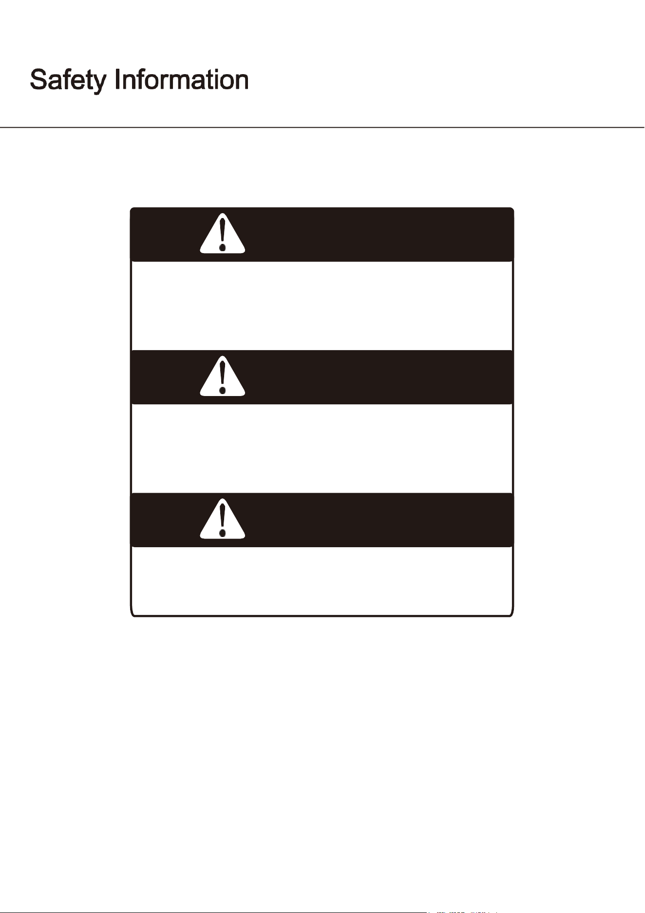
DANGER
Danger means that failure to heed this safety
statement may result in severe injury or death.
WARNING
Warning means that failure to heed this safety
statement may result in extensive product damage,
serious personal injury, or death.
CAUTION
Caution means that failure to heed this safety
statement may result in minor or moderate
personal injury, property or equipment damage.
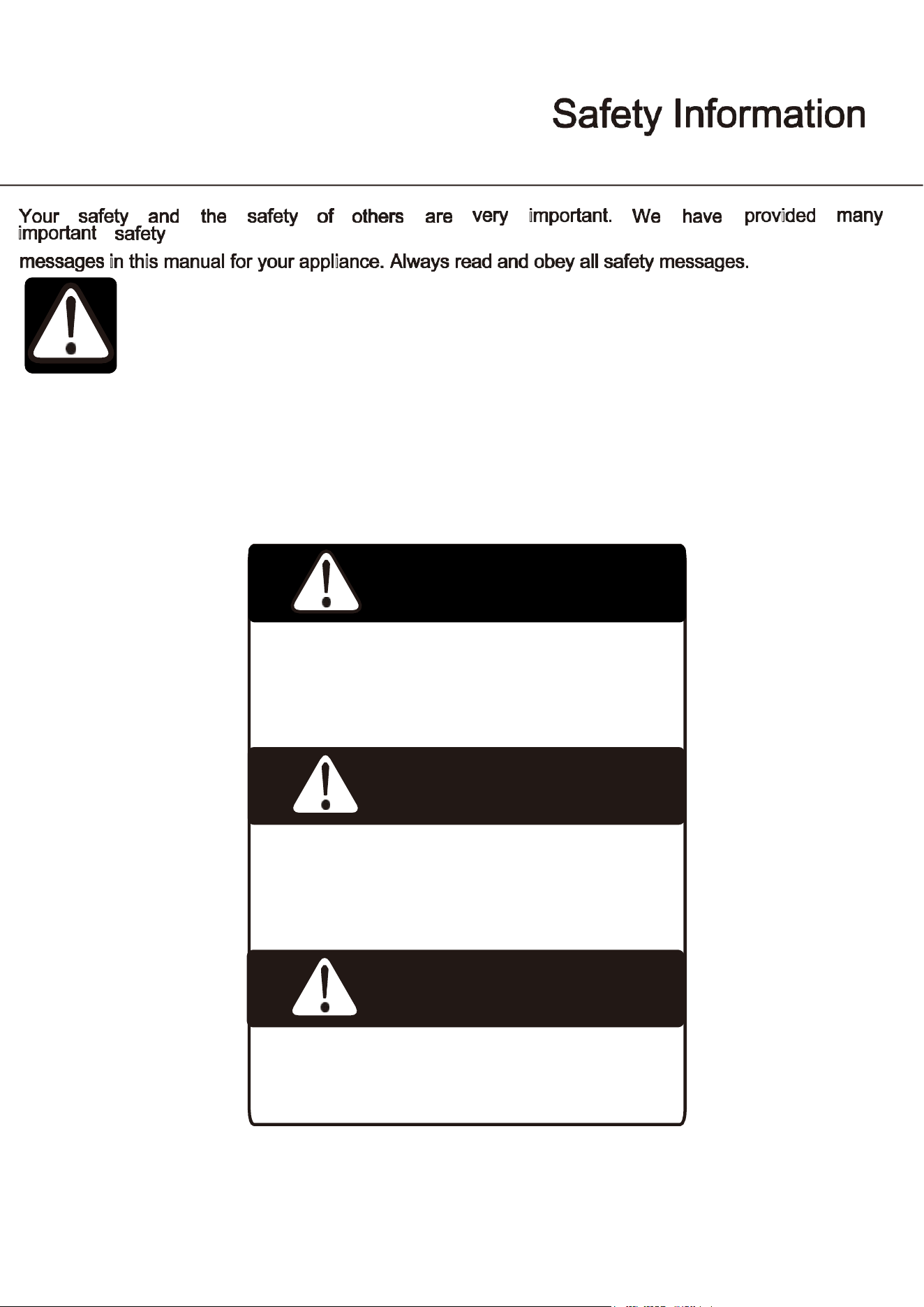
This is the Safety Alert Symbol. This symbol alerts you to potential hazards that can cause
severe bodily injury or death.
All safety messages will follow the Safety Alert Symbol and either the words “DANGER”
“WARNING” OR
“CAUTION”
Use, Care, and Installation Guide
4
DANGER
When using an electrical appliance, basic precautions should
always be followed to reduce the risk of fire, electric shock, and
injury to persons.
WARNING
To reduce the risk of
fi
re, electric shock or personal injury, unplug
or disconnect the appliance from the power supply before
servicing.
CAUTION
Flammable refrigerant used! When handling, moving and use of
the refrigerator,make sure to avoid either damaging the
refrigerant tubing, or increasing the risk of a leak.
General Safety
►
Use this appliance only as described in this manual. Other uses not recommended may cause
fi
re,
electric shock or personal injury.
►
This appliance is not intended for use by young children or infirm persons unless they have been
adequately supervised by a responsible person to ensure that they can use the appliance safely.
►
Young children should be supervised to ensure that they never play with the appliance.
►
To protect against the risk of electric shock, NEVER IMMERSE the unit, cord, or plug in water or
spray any other liquid.
►
Unplug the appliance from the plug socket when not in use, when moving from one location to
another and before cleaning.
Use, Care, and Installation Guide
5
WARNING
Prop. 65 Warning for California Residents: This product may
contain chemicals known to the State of California to cause
cancer, birth defects, or other reproductive harm.
For your safety, read all instructions carefully before operating the appliance.
►
To disconnect the appliance, grip the plug and pull it from the wall outlet. Never pull by the cord.
►
Never operate the appliance in the presence of explosive and/or Flammable fumes.
►
Never place the appliance or any of its parts near an open flame, cooking or other heating
appliance.
►
Never operate the appliance with a damaged cord or plug, if the product malfunctions, or if it is
dropped or damaged in any manner.
►
The use of attachments not recommended by the manufacturer may be hazardous.
►
Never operate if the housing is removed or damaged.
►
A loose
fi
t between the AC outlet (receptacle) and plug may cause overheating and a distortion of
the plug. Contact a Qualified electrician to replace loose or worn outlet.
►
Locate the unit away from direct sunlight and sources of heat (stove, heater, radiator, etc.).
►
This appliance is CFC and HFC free and contains small quantities of isobutane (R600a), an
environmentally friendly coolant.
►
CAUTION – Risk of fire or explosion due to puncture of refrigerant tubing; follow handling
instructions carefully. Flammable refrigerant used.
►
You must ensure that the cooling circuit is undamaged when installing the appliance. However,if it
becomes damaged, avoid proximity to open
fi
res and heat sources of all kinds. The room in which
the appliance is located should be ventilated properly and according to state and local codes.
►
Never use an appliance with a damaged circuit.
►
Ensure that the ventilation openings to and from a built-in appliance are never blocked or covered.
►
No liability will be accepted for any damage caused by misuse of the appliance, or as a result of
repairs carried out by unqualified person. In this case neither the warranty nor any other liability
claims will apply.
Use, Care, and Installation Guide
6
WARNING
To reduce the risk of fire, electric shock or personal injury, unplug
or disconnect the appliance from the power supply before
servicing.
WARNING
Never operate any other electrical appliance inside this
appliance.
►
Never attempt to repair or replace any part of your appliance unless it is speci
fi
cally
recommended in this manual. All other servicing should be referred to a quali
fi
ed technician.
►
DANGER – Risk of fire or explosion. Flammable refrigerant used. To be repaired only by
trained service personnel. Use only manufacturer authorized service parts. Any repair
equipment used must be designed for
fl
ammable refrigerants. Follow all manufacturer
repair instructions. Do not puncture refrigerant tubing.
►
DANGER – Risk of
fi
re or explosion. Flammable refrigerant used. Do not use mechanical
devices to defrost refrigerator. Do not puncture refrigerant tubing.
►
Replace all access panels before operating.
►
Use two or more people to move and install the appliance. Failure to do so can result in back or
other injury.
►
Never clean appliance parts with flammable liquids. These fumes can create a
fi
re hazard or
explosion. Never store or use gasoline or other flammable vapors and liquids in the vicinity of this
or any other appliance. The fumes can create a fire hazard or explosion.
►
Never connect or disconnect the electric plug with wet hands.
►
It is recommended that a separate circuit, serving only your appliance be provided. Use
receptacles that cannot be turned off by a switch or pull chain.
Use, Care, and Installation Guide
7
WARNING
Please ensure that old, worn appliances are rendered unusable
before disposal by removing the plug, cutting the power cable,
and removing or destroying any snap fastenings or bolts. You will
thus prevent children from locking themselves in the appliance
during play (Risk of suffocation) or endangering their lives in any
other way.
For your safety, read all instructions carefully before operating the appliance.
Save These Instructions
If you are experiencing problems, check the Troubleshooting Guide at the back of this manual. It lists causes
of minor operating problems that you can correct yourself.
Disposal of Old Appliance
Dispose of your appliance packaging properly. Refrigeration equipment must be properly disposed
of in a way which protects the environment. This applies to your old appliance and to your new unit
once it has reached the end of its service life.
►
WARNING: Risk of child entrapment. Before you throw away your old refrigerator or freezer,
Take off the doors. Leave the shelves in place so that children may not easily climb inside.
►
CAUTION – Risk of
fi
re or explosion. Dispose of refrigerator properly in accordance with the
applicable federal or local regulations. Flammable refrigerant used.
►
The appliance must not be disposed with normal household waste collection.
►
The coolant circuit, particularly the heat exchange at the back/bottom of the unit, must not be
damaged.
►
The symbol on the product or its packaging indicates that this product is not to be handled
as normal household waste but is to be taken to a recycling collection point for electrical and
electronic goods. By correctly disposing of this product you are contributing to the protection of
the environment. Improper disposal endangers health and the environment. Further information
about the recycling of the product may be obtained from your town hall or local waste
collection department.
Use, Care, and Installation Guide
8
WARNING
Do not store or install the appliance outdoors.
Before Using Your Appliance
►
Remove all exterior and interior packing.
►
Before connecting the appliance to the power source, let it stand upright for approximately 2
hours. This will reduce the possibility of a malfunction in the cooling system caused by handling
during transportation.
►
Clean the interior surface with warm water using a soft cloth.
►
The door on this appliance can be opened from either the left or the right side. The unit is delivered
with the door opening on the left side. Should you wish to open the door from the right, follow the
instructions, “Reversing the Door Swing of your Appliance,” listed below.
Installation of Your Appliance
►
The appliances are designed for either built-in, or free-standing installation.
►
Place your appliance on a floor that is strong enough to support it when it is fully loaded. To level
your appliance, adjust the 4 legs until level.
►
Locate the appliance away from direct sunlight and sources of heat (stove, heater, radiator,
etc.). Direct sunlight may a
ff
ect the acrylic coating and heat sources may increase electrical
consumption. Extreme cold ambient temperatures may also cause the unit not to perform
properly.
►
Never place the unit in damp areas.
►
Plug the appliance into an exclusive, easily accessible electrical socket.
►
Any questions concerning power and/or electrical connection should be directed towardsa
qualified electrician or an authorized products service center.
►
The air vent at the front of the appliance must never be covered or blocked in any way.
Safety Information
Use, Care, and Installation Guide
9
For your safety, read all instructions carefully before operating the appliance.
►
The appliance must be installed to all electrical connections in accordance with state and local
codes.
►
Use two or more people to move and install the beverage cooler. Failure to do so can result in back
or other injury.
►
The cooler may experience decreased cooling efficiency if air flow is restricted due to a
fully loaded cabinet.
►
Install the beverage cooler in a well-ventilated area where the ambient temperature is above 50ºF
and below 90ºF.
Attention
►
Never overload the cabinet.
►
Never open the door unless necessary.
►
Never cover shelves with aluminum foil or any other shelf material which may prevent air
circulation.
►
Should the appliance be left empty for long periods, it is suggested that the appliance be
unplugged, and, after careful cleaning, leave the door ajar to allow air to circulate inside the
cabinet in order to avoid possible condensation, mold or odors from forming.
Use, Care, and Installation Guide
10
WARNING
Improper use of the grounded plug can result in the risk of
electrical shock. If the power cord is damaged, have it replaced
by a qualified electrician or an authorized service center.
Electrical Connection
Check that the voltage marked on the product corresponds with your supply voltage.
This appliance should be properly grounded for your safety. The power cord of this appliance is
equipped with a three-pin plug which mates with standard three-pin wall outlets to minimize
the possibility of electrical shock.
Never under any circumstances cut or remove the third ground prong from the power cord supplied.
For personal safety, this appliance must be properly grounded.
Have the wall outlet and circuit checked by a qualified electrician to make sure the outlet is properly
grounded. When a standard two-pin wall outlet is encountered, it is your responsibility and obligation
to have it replaced with a properly grounded three-pin wall outlet.
To prevent accidental injury, the cord should be secured behind the appliance and not left exposed or
dangling.
The appliance should always be plugged into its own individual electrical outlet which has a voltage
rating that matches the rating label on the appliance. This provides the best performance and also
prevent overloading wiring circuits that could cause a fire hazard from overheating. Never unplug
the appliance by pulling the power cord. Always grip the plug firmly and pull straight out from the
receptacle. Repair or replace immediately all power cords that have become frayed or otherwise
damaged. Never use a cord that shows cracks or abrasion damage along its length or at either end.
When moving the appliance, be careful not to damage the power cord.
Never use your appliance with an extension cord unless this cord has been checked and tested by a
qualified technician or service person. The extension cord must be a UL/CUL Listed, 3-wire grounding
extension cord that has a grounding plug and outlet and that the electrical rating of the cord is 115
volts and at least 10 amperes.
Safety Information
Use, Care, and Installation Guide
11
Thank you for purchasing your beverage cooler.
This manual contains important information regarding the proper installation, use, and maintenance
of your beverage cooler. Following this manual will ensure that your product will work at its peak
performance and efficiency.
For Your Records
Please write down the model number and serial number below for future reference. Both numbers are
located on the rating label on the back of your unit or inside of the unit and are needed to obtain
warranty service. You may also want to staple your receipt to this manual as it is the proof of your
purchase and may also be needed for service under warranty.
Model Number:
Serial Number:
Date of Purchase:
To better serve you, please do the following before contacting customer service:
If you received a damaged product, immediately contact the retailer or dealer that sold you the
product.
►
Read and follow this instruction manual carefully to help you install, use and maintain your
unit.
►
Read the troubleshooting section of this manual as it will help you diagnose and solve common
issues.
Use, Care, and Installation Guide
12
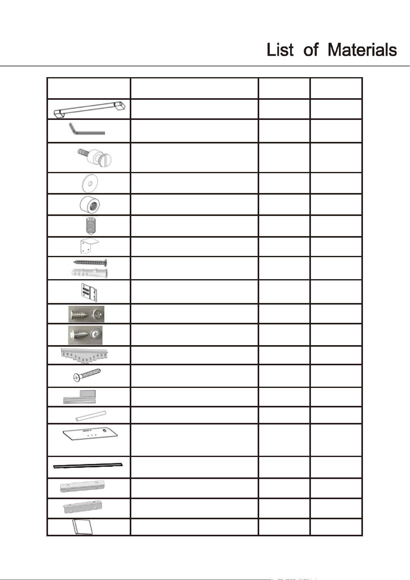
Quantity Part
Door handle (if applicable)
1 1
Allen/hex key (if applicable
)
1 1
Handle mounting fastener
(if applicable
)
2 2
Gasket (if applicable)
2 2
Stop nut,M5 (if applicable
)
2 2
set screw,M5*10 (if applicable)
2 2
Anti-tip bracket
2 2
Anti tip bracket screws and dowels
8 8
Bracket furniture
8 8
Counter sunk head screw,ST4x14 20 20
Truss washer head,ST4*12 16 16
Position adjustment part
1 1
Countersunk head screws for fixing
wooden doors ST4x35
8 8
Air vent hinge part(if applicable)
\ 1
90
°
limit pin
1 1
Furniture door preparation
template
1 1
Decorative parts
1+2 1+2
\ 1
Hinge bracket(only for 24")
\ 1
User manual
1 1
Hinge bracket(
only for 24")
EWC18SRN683 EWC24SRN103
Use, Care, and Installation Guide
`
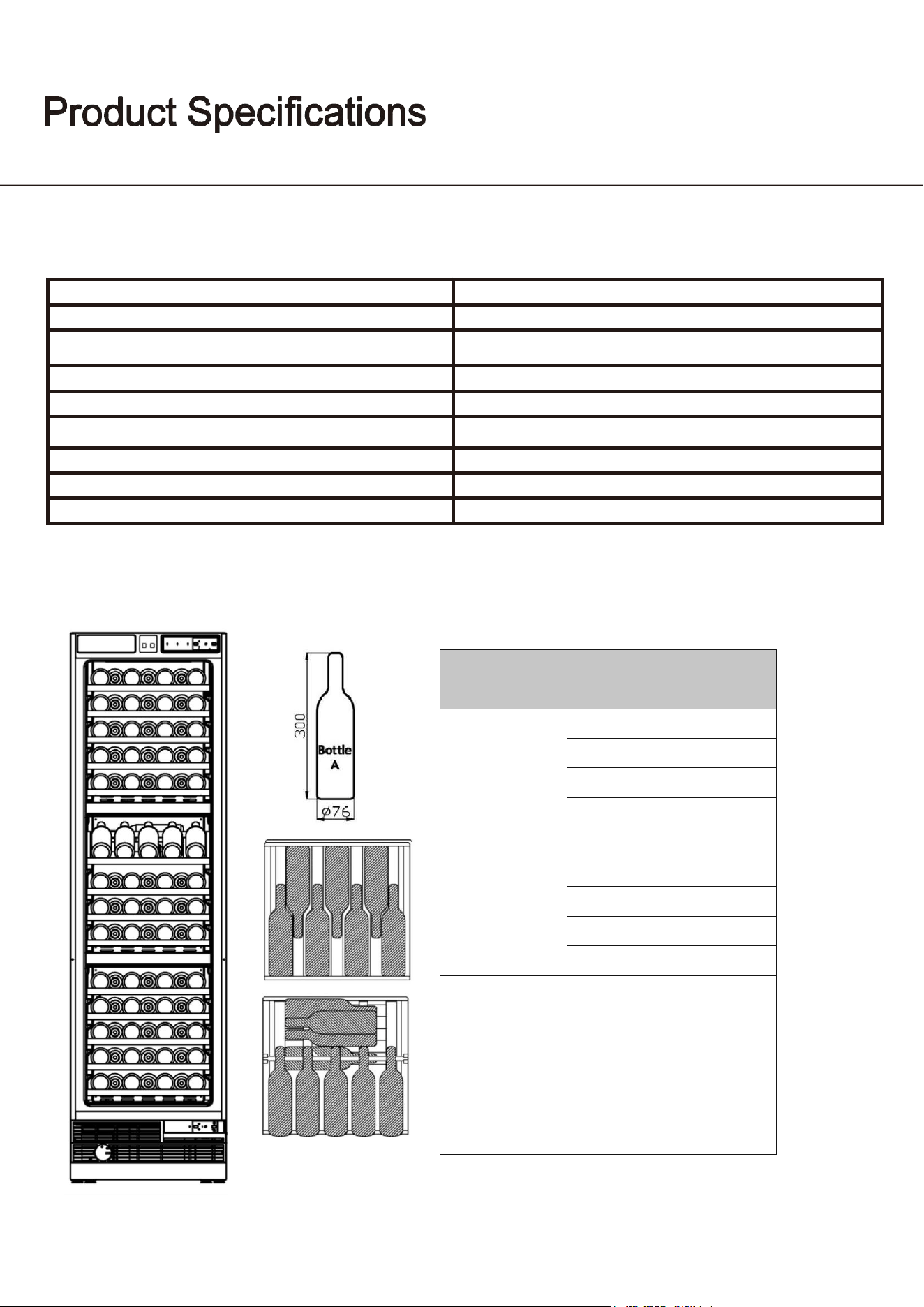
Internal Storage UWFC18BNNPRY
13
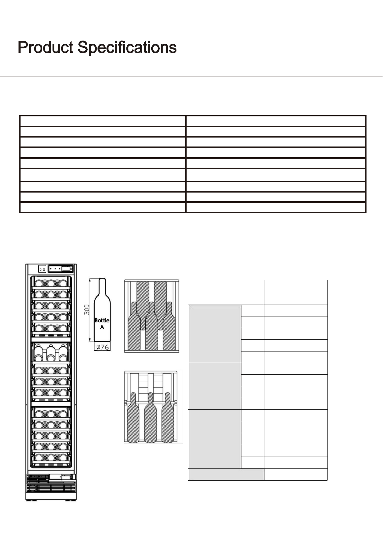
DESCRIPTION OF PRODUCT
wine cooler
MODEL
UWFC18BNNPRY UWFC24BNNPRY
VOLTAGE/FREQUENCY
AC 115/ 50&60Hz
AMPERAGE
1.5A
COLOR
White OR Grey
STORAGE CAPACITY∗
68 & 62 Bottles
REFRIGERANT
R600a
TEMPERATURE RANGE
41°F - 68°F
DIMENSIONS (HxWxD)
83 9/16 x 17 3/4 x 23 1/2(2130x451x597mm)
*Storage capacity is based on standard 12 oz. cans and 750 ml. Bordeaux-style wine bottles.
`
Internal Storage UWFC18BNNPRY
Load
capacity
Bottle
storage
(Bottle
A)
Upper zone
1
5
2
5
3
5
4
5
5
5
Middle zone
1
3
2
5
3
5
4
5
Lower
zone
1
5
2
5
3
5
4
5
5
5
Total
68
Use, Care, and Installation Guide
14
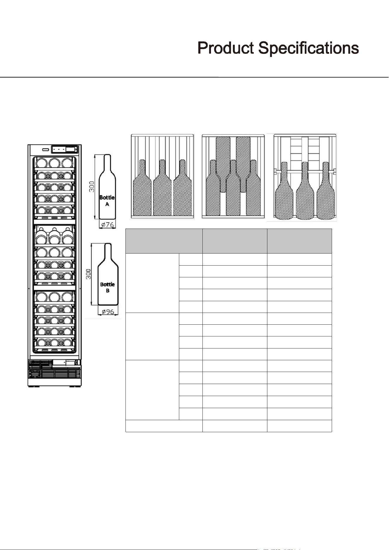
Internal Storage UWFC18BNNPRY
Load
capacity
Bottle storage
(Bottle
A)
Bottle storage
(Bottle
B)
Upper
zone
1
\
3
2
5
\
3
5
\
4
5
\
5
5
\
Middle zone
1
\
3
2
\
3
3
5
\
4
5
\
Lower
zone
1
\
3
2
5
\
3
5
\
4
5
\
5
5
\
Total
50
12
Use, Care, and Installation Guide
Parts Identification UWFC24BNNPRY
15
DESCRIPTION OF PRODUCT
wine cooler
MODEL
UWFC24BNNPRY
VOLTAGE/FREQUENCY
AC 115/ 50&60Hz
AMPERAGE
1.5A
COLOR
White or Grey
STORAGE CAPACITY∗
100 & 94 Bottles
REFRIGERANT
R600a
TEMPERATURE RANGE
41°F - 68°F
DIMENSIONS (HxWxD)
83 9/16 x 23 3/4 x 23 1/2(2123 x 603 x 597mm)
*Storage capacity is based on standard 12 oz. cans and 750 ml. Bordeaux-style wine bottles.
`
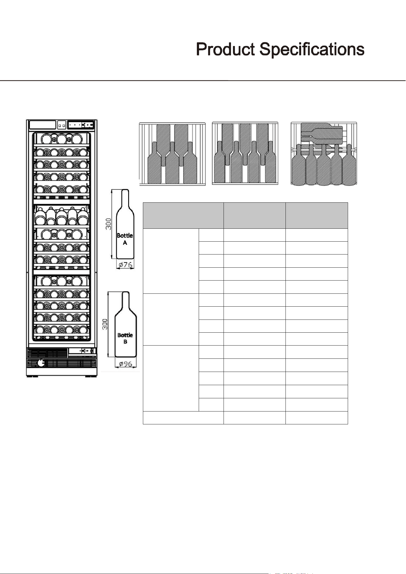
Internal Storage UWFC24BNNPRY
Load
capacity
Bottle
storage
(Bottle
A)
Upper
zone
1
7
2
7
3
7
4
7
5
7
Middle zone
1
9
2
7
3
7
4
7
Lower
zone
1
7
2
7
3
7
4
7
5
7
Total
100
Use, Care, and Installation Guide
16
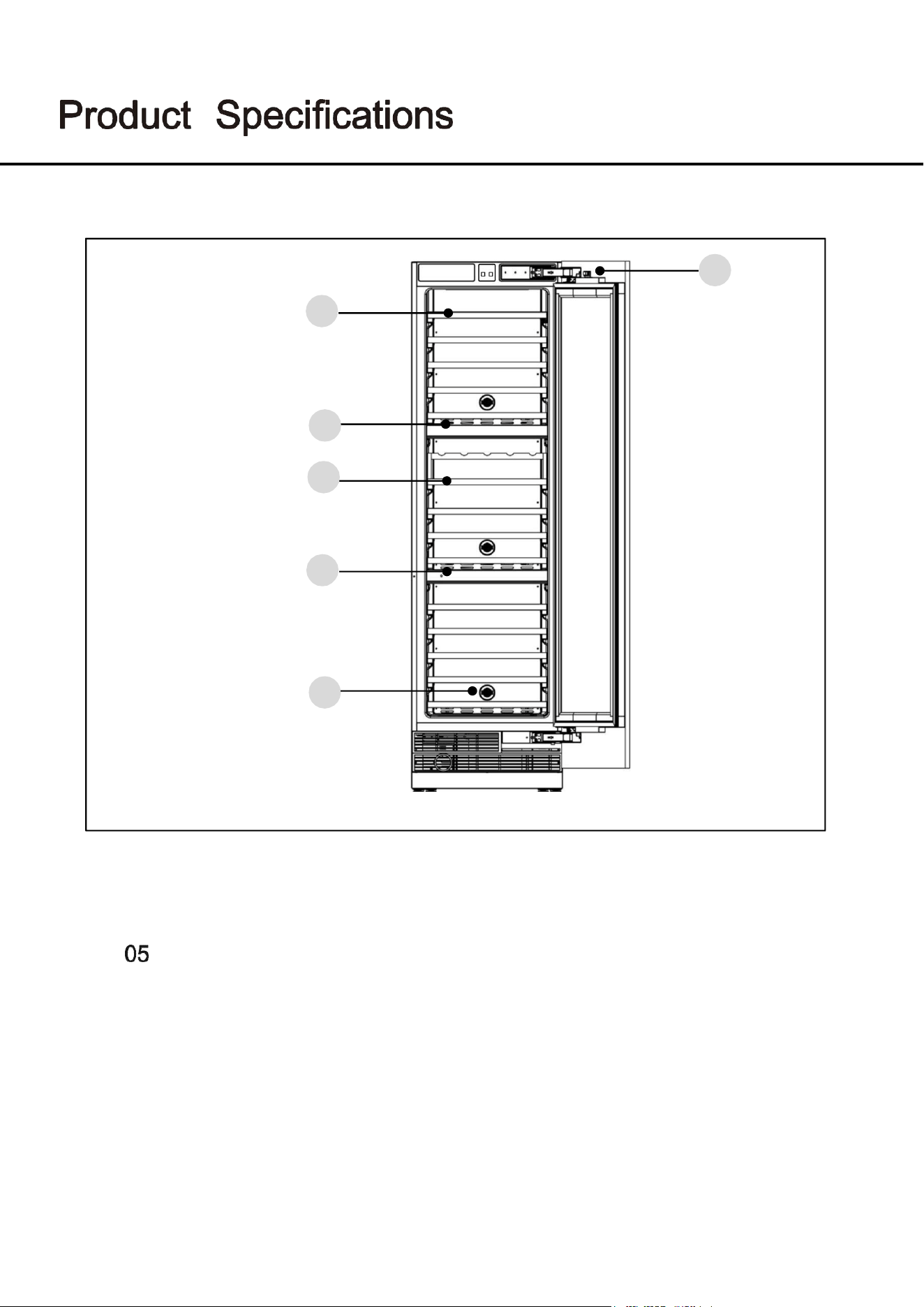
Internal Storage UWFC24BNNPRY
Load
capacity
Bottle
storage
(Bottle
A)
Bottle storage
(Bottle
B)
Upper
zone
1
\
5
2
7
\
3
7
\
4
7
\
5
7
\
Middle zone
1
6
3
2
\
5
3
7
\
4
7
\
Lower
zone
1
\
5
2
7
\
3
7
\
4
7
\
5
7
\
Total
76
18
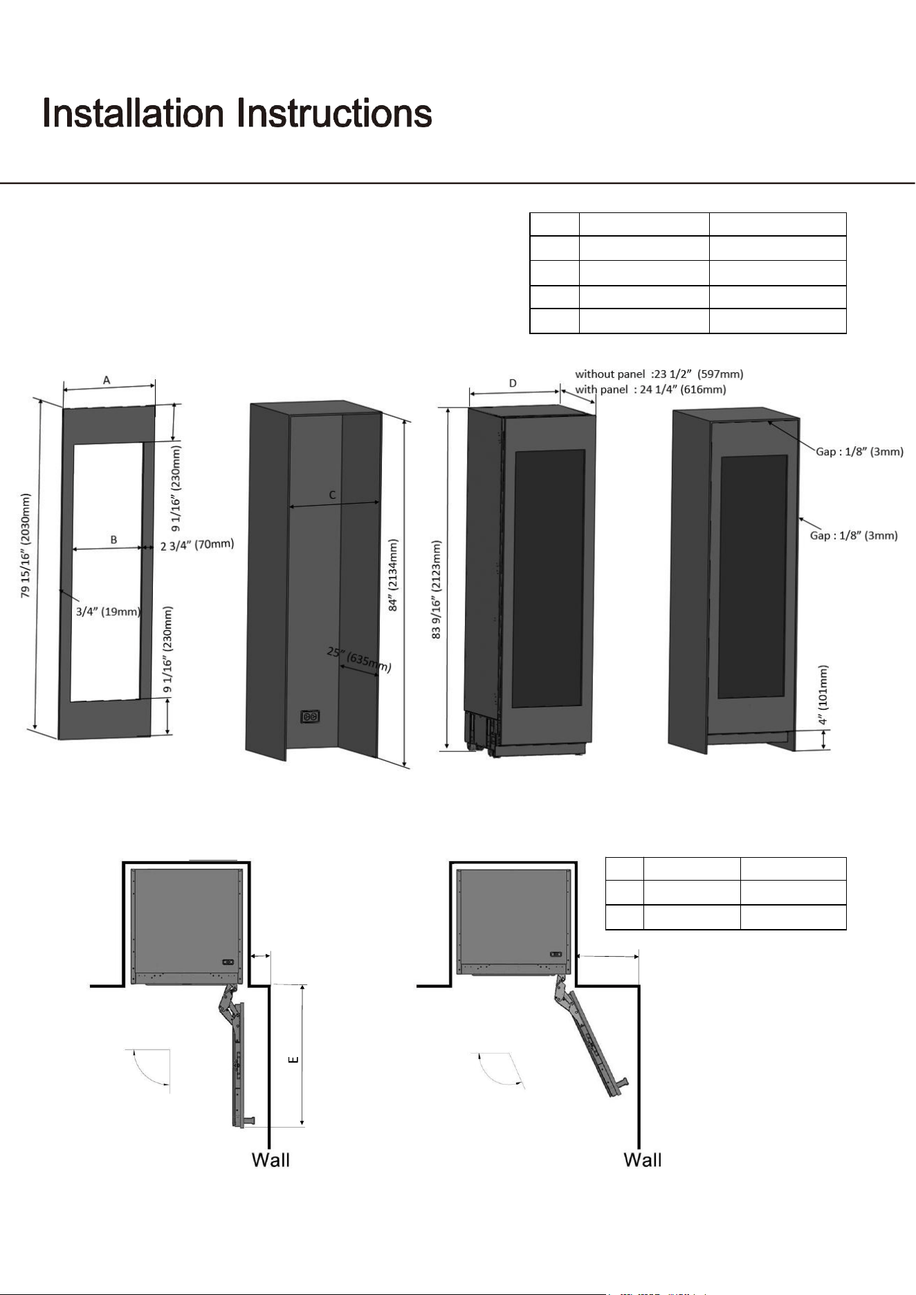
Parts Identification UWFC24BNNPRY
Use, Care, and Installation Guide
17
05
01
02
03
02
04
01 Wine Shelf A
03 Wine Shelf B
Electromagnetic Switch
02 Control Panel & Compartment Wall
04
Carbon Filter
Use, Care, and Installation Guide
18
4 3/8" (110mm)
F
90
°
Door swing
115
°
Door swing
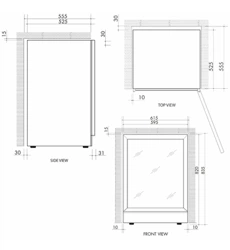
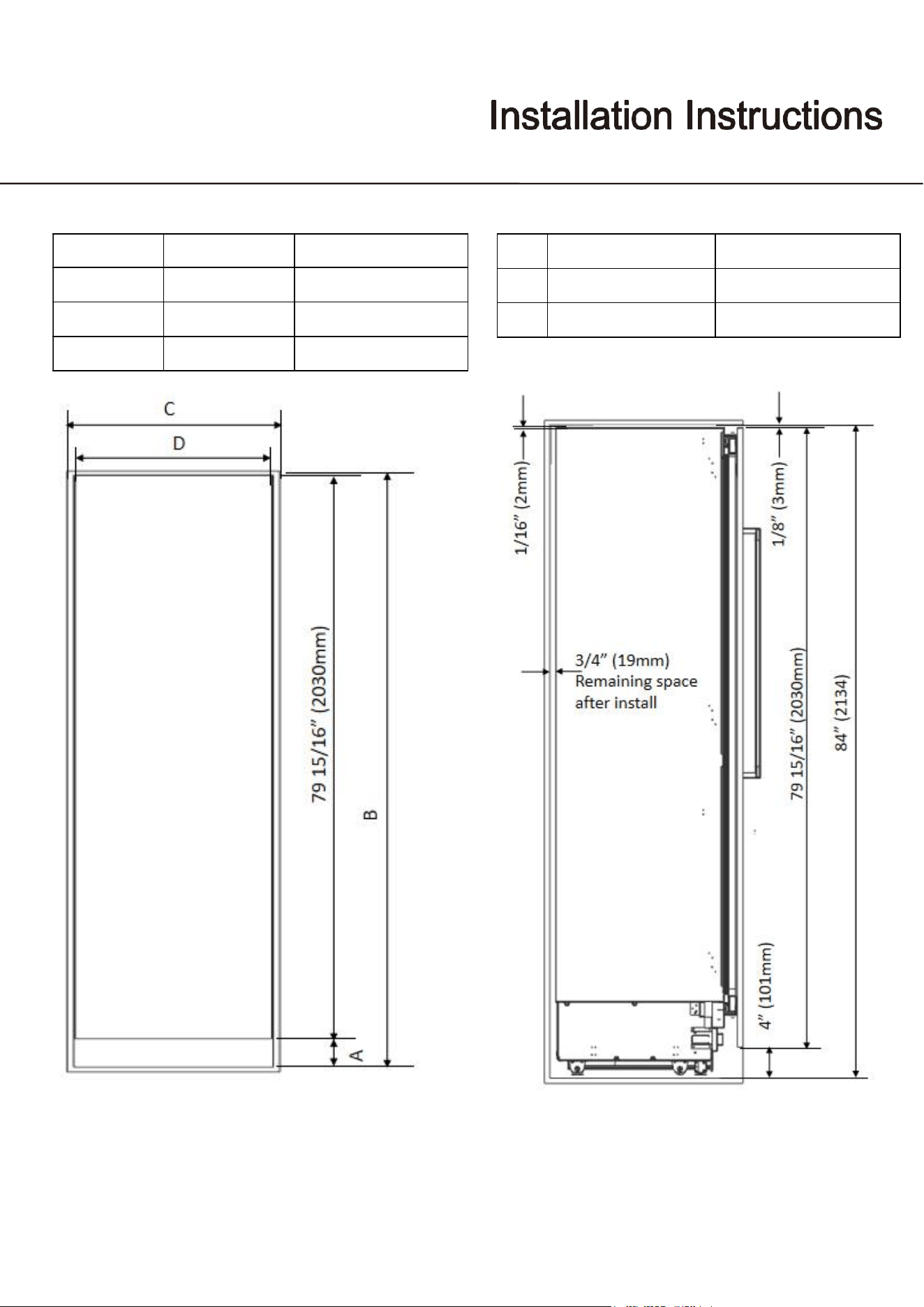
Installation dimensions
Wood panel cutout dimension and installation clearance
Installation dimensions
UWFC18BNNPRY
UWFC24BNNPRY
E
20" (508mm)
26" (660mm)
F
11" (280mm)
14" (356mm)
UWFC18BNNPRY
UWFC24BNNPRY
A
1
7 3/4
" (45
1
mm)
23 3/4" (603mm)
B
12 1/4" (311mm)
18 1/4" (463mm)
C
18" (457mm)
24
" (
609
mm)
D
17 3/4" (451mm)
23 3/4" (603mm)
Use, Care, and Installation Guide
19
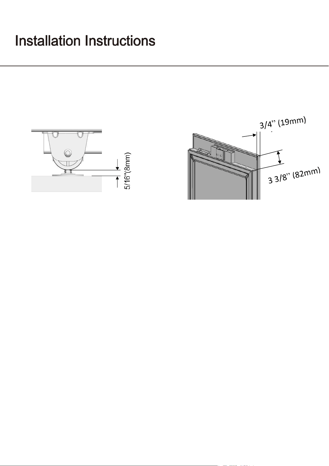
C
18" (457mm)
24" (609mm)
D
17 3/4"(451mm)
23 3/4"(603mm)
A
B
standard
4"(101)
84” (2134)
minimum
3 3/4"(95)
83 3/4" (2127)
maximum
5 5/16" (135)
85 5/16" (2167)
UWFC18BNNPRY
UWFC24BNNPRY
Use, Care, and Installation Guide
20
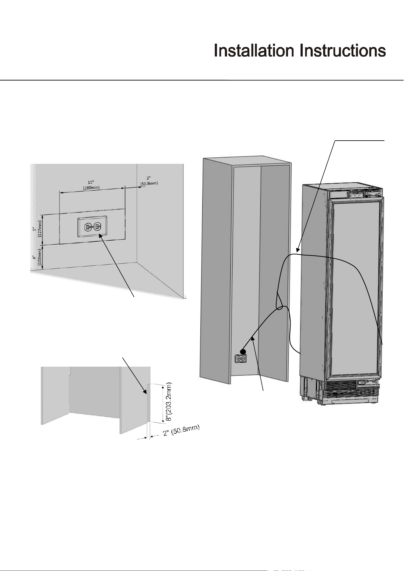
Anti tip brackets location
Minimum height
adjustment for leveling
Assembly dimension between
Wood panel and fridge door
24”
Use, Care, and Installation Guide
21
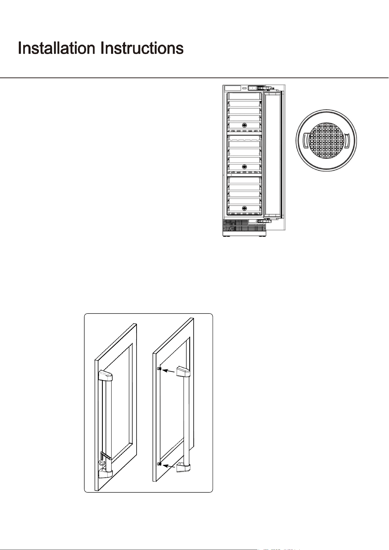
Electrical location
Nylon string
Cable location
Keep for Power cord
Power cord
Power cord installation
Use nylon string to prevent the cable
from getting jammed.
Use, Care, and Installation Guide
22
Carbon Filter
A built-in carbon
fi
lter protects your beverages by acting
as a natural barrier against harmful odors. The carbon
filter should be replaced every 3-6 months depending on
the unit’s exposure level to odor. If the unit is placed in a
kitchen, regular replacement every three months is ideal.
Remove the carbon
fi
lter by turning counterclockwise to
unlock from rear panel.
Install the handle (if applicable)
If a pro handle or di
ff
erent colored contemporary handles are desired, refer below for the handle
dimensions and part number.
1. Align the handle
fi
xing holes with the holes on the wooden door, then install the handle with
a screwdriver.
Use, Care, and Installation Guide
23
Changing the door opening direction
UWFC24BNNPRY
Should you desire to reverse the opening direction of the door, please follow the instructions below.
Safely reversing the door swing of your appliance should require at least two people.
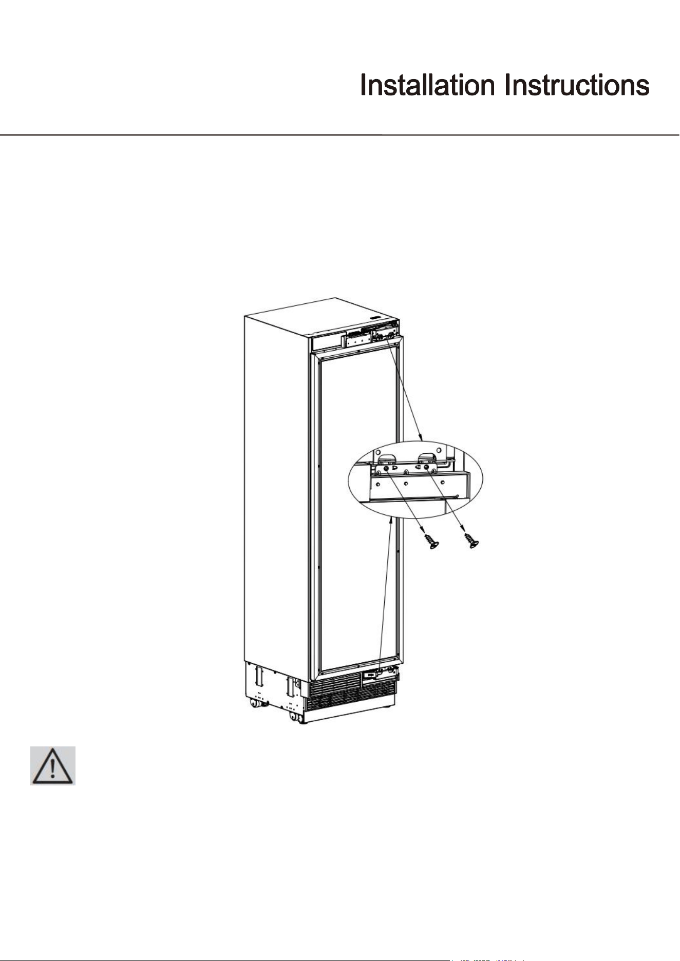
● Remove the hinge connection screws of the Hinge Brackets.1
2
3
4
5
6
7
8
9
10
11
12
13
14
15
16
17
18
19
20
21
22
23
24
25
26
27
28
29
30
31
ATTENTION:32
The clad door will be released when these screws are removed.33
You must take measures to prevent the door from falling.34
You can tape the Furniture Door to the Inner Door or ask for help from another person.35
36
37
Use, Care, and Installation Guide
24
38
39
40
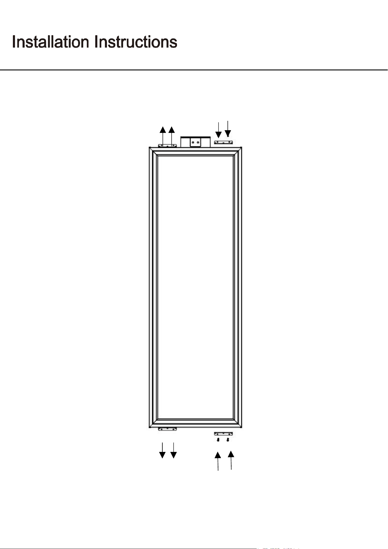
● Take out door and lay it down on a table.41
● Remove the hinge brackets on the fridge door.42
● Take out the new hinge brackets from Accessories bag and screw it on the reverse side.43
44
45
46
Use, Care, and Installation Guide
25
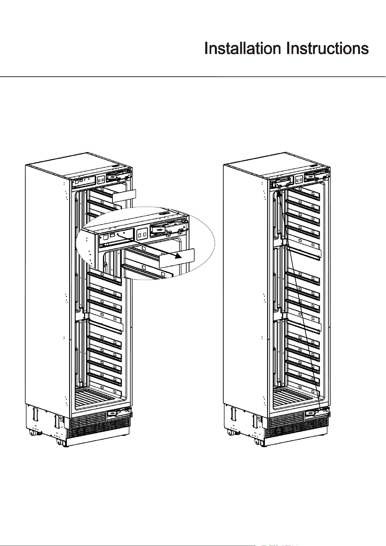
● Remove the Hinge Caps located at the other side where you will fix the hinges.
● Remove the lower right hinge by loosening its 2 screws and fix it to its slot at the upper left side.
Use, Care, and Installation Guide
26
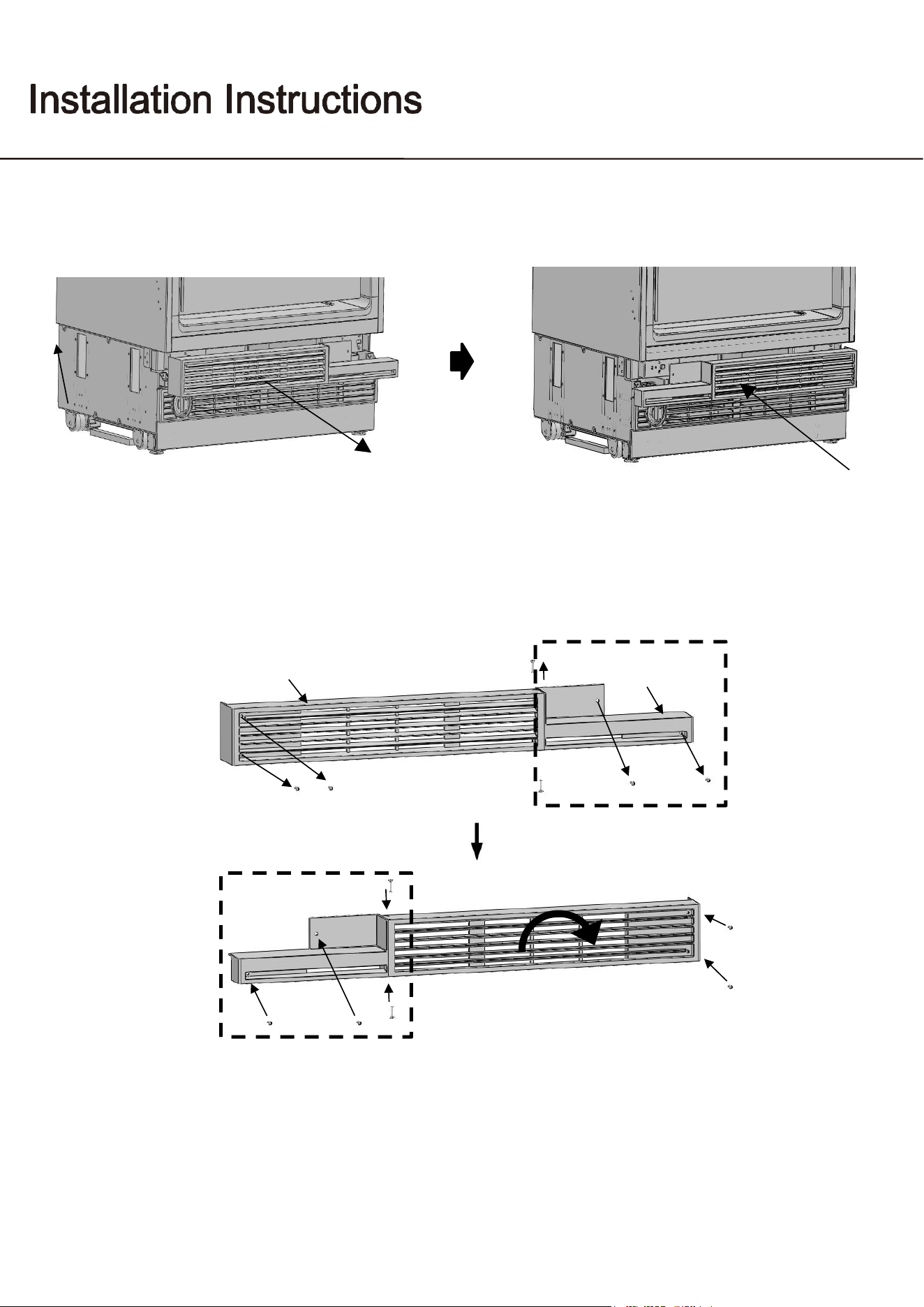
● Remove the air vent part and change direction as shown figure.
Air vent cover
Air vent hinge part right
Rotate air vent cover by 180°
Air vent hinge part left
Air vent upper part for the right hinge
● How to change air vent upper part direction
Air vent upper part for the left hinge
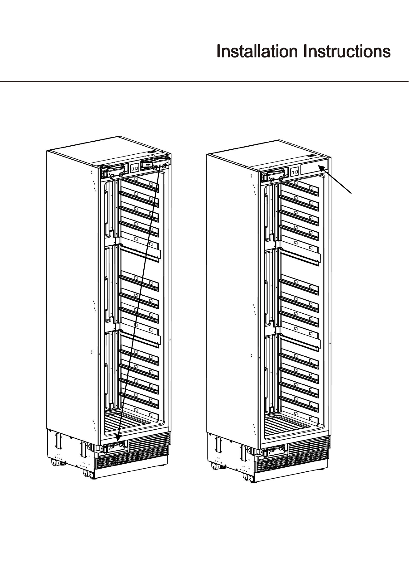
Use, Care, and Installation Guide
27
● Remove the upper right hinge by loosening its 2 screws and fix it to its slot at the lower left side.
● Attach the Hinge Slot Caps removed from the left side to the Hinge Caps to the right side.
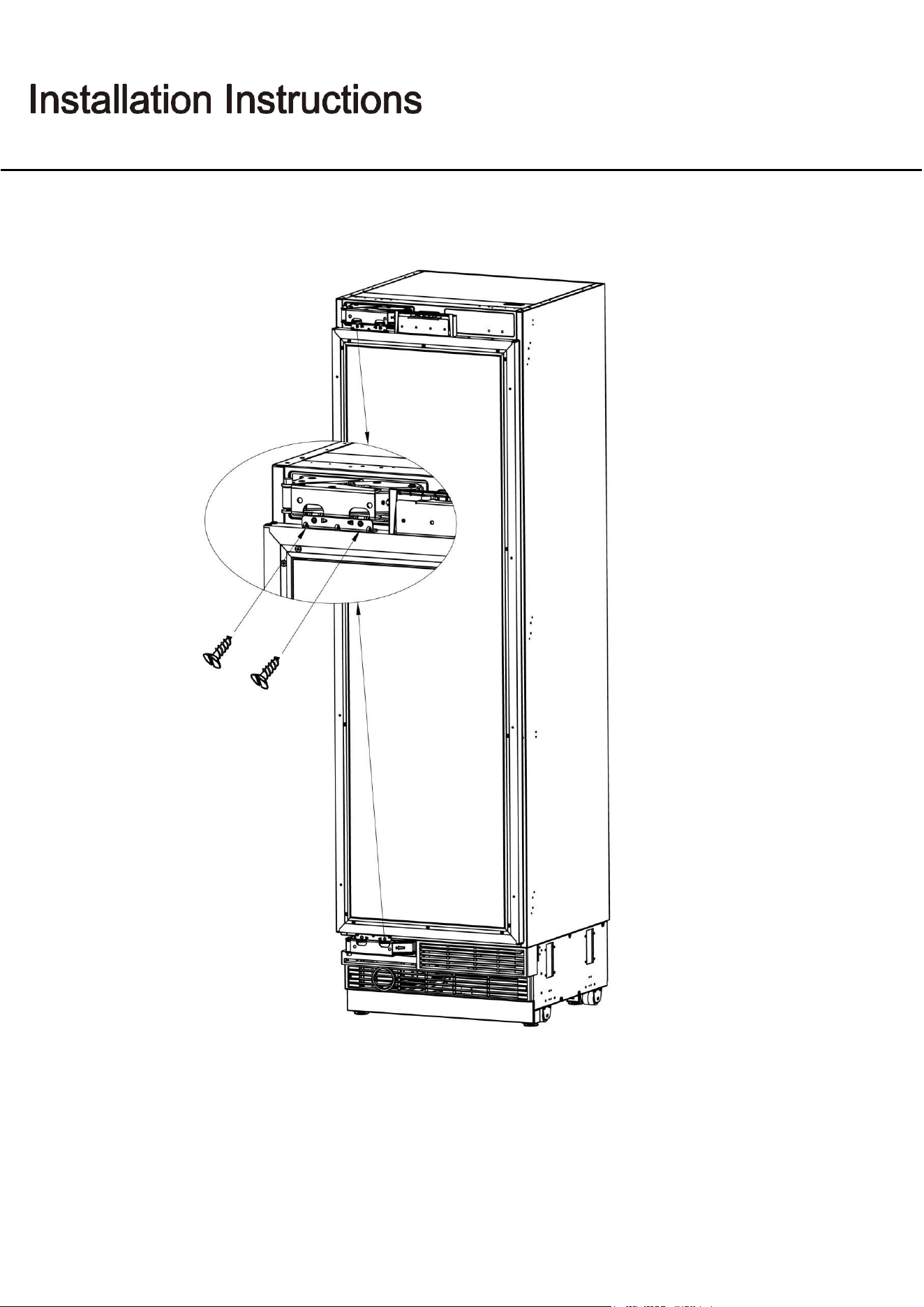
Use, Care, and Installation Guide
28
● Place the door to the refrigerator and fix it with 4 screws.
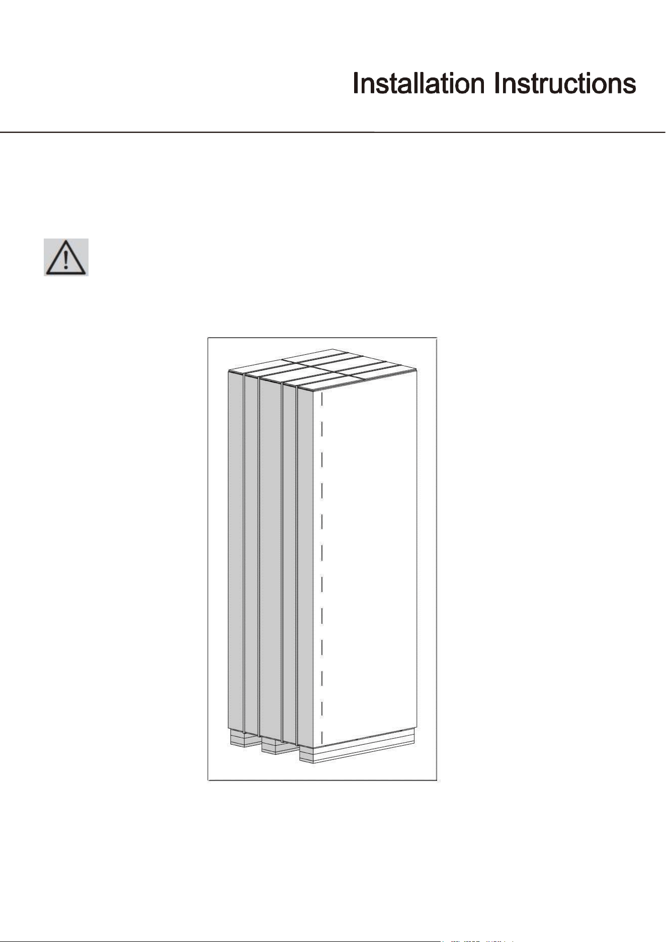
Use, Care, and Installation Guide
29
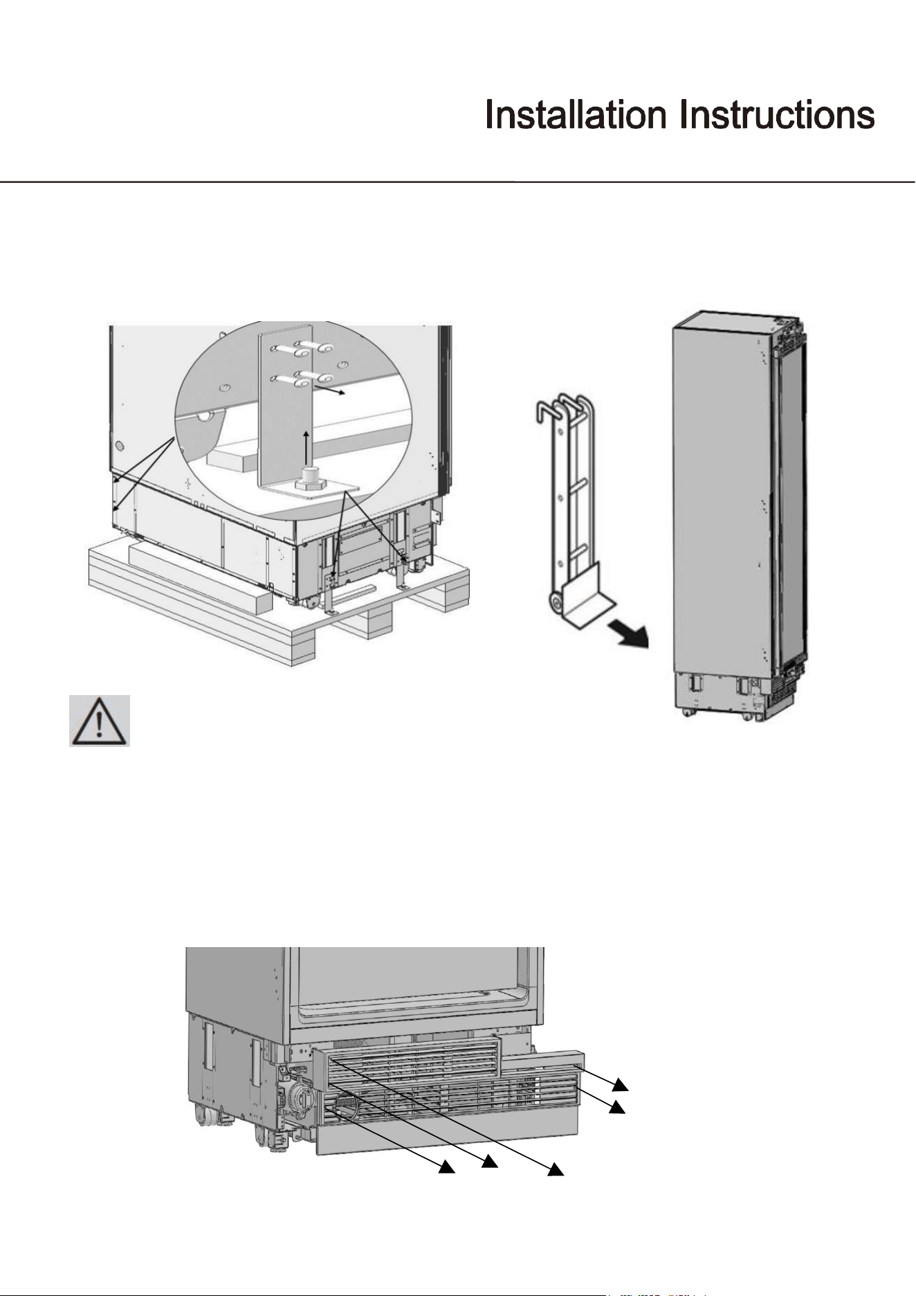
Removing the packing
● Use a box cutter to remove the tapes.
● Cut the Packaging Board with a Box Cutter through the section illustrated in dotted lines and remove it.
At least two persons must carry the refrigerator.
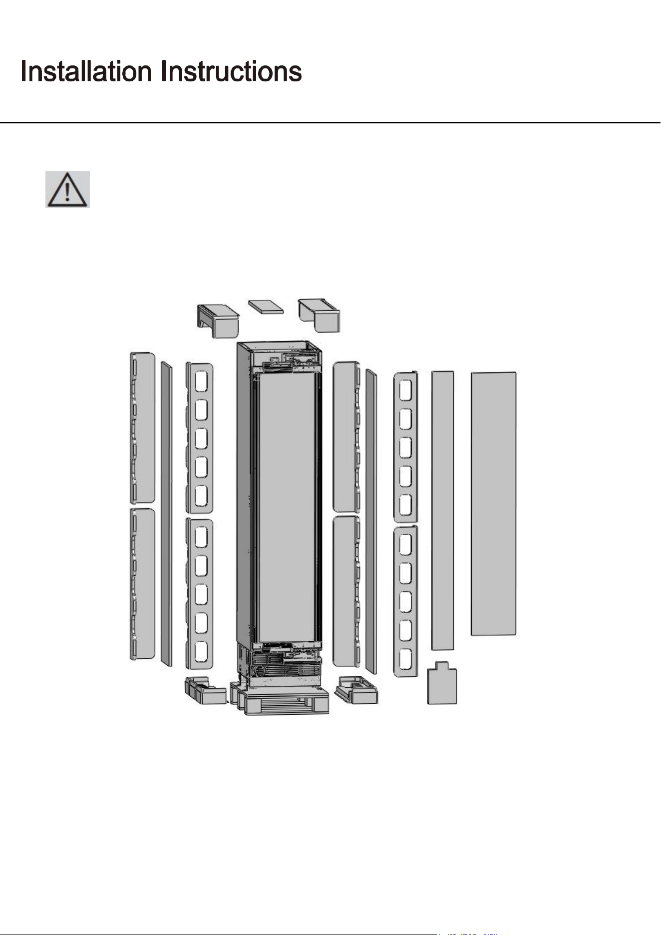
Use, Care, and Installation Guide
30
● Remove the Packaging Polystyrene material.
Do not remove the tape of the upper door on the product until the refrigerator is placed into the
cabin. Risk of tipping over.
Use, Care, and Installation Guide
31
Taking the refrigerator from the wooden pallet
● Remove the brackets that connect the refrigerator to the Wooden Pallet.
● Recline the wine cooler slowly and pull back with the help of the cart, and then land it.
The risk of tipping over is high as of this point. You should not open the doors
until the product is placed into the cabin.
Removing the vent hole assembly
● Remove 5 screws to take out the Vent Hole Assembly.
Use, Care, and Installation Guide
32
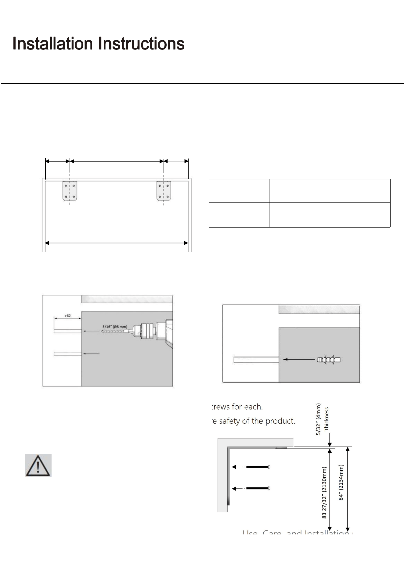
Mounting the anti-tip brackets
● Mark the wall for anti-tip brackets
● Use a drill to create holes for dowels at the ● Use the hammer to fit the dowels
marked points. (5/16” -Ø8)
● Fit the brackets into their places, using 4 screws for each.
● You must use all of the 2 brackets to ensure safety of the product.
Please remember to use the necessary protective
equipment when drilling holes on the wall and
performing installation.
Category
A
18” (457mm)
24” (609mm)
B
11 5/8 (295mm)
17 5/8 (447mm)
C
3 3/16" (81mm)
3 3/16" (81mm)
B
C
C
Anti-tip brackets on the wall
A
UWFC18BNNPRY
UWFC24BNNPRY
Use, Care, and Installation Guide
33
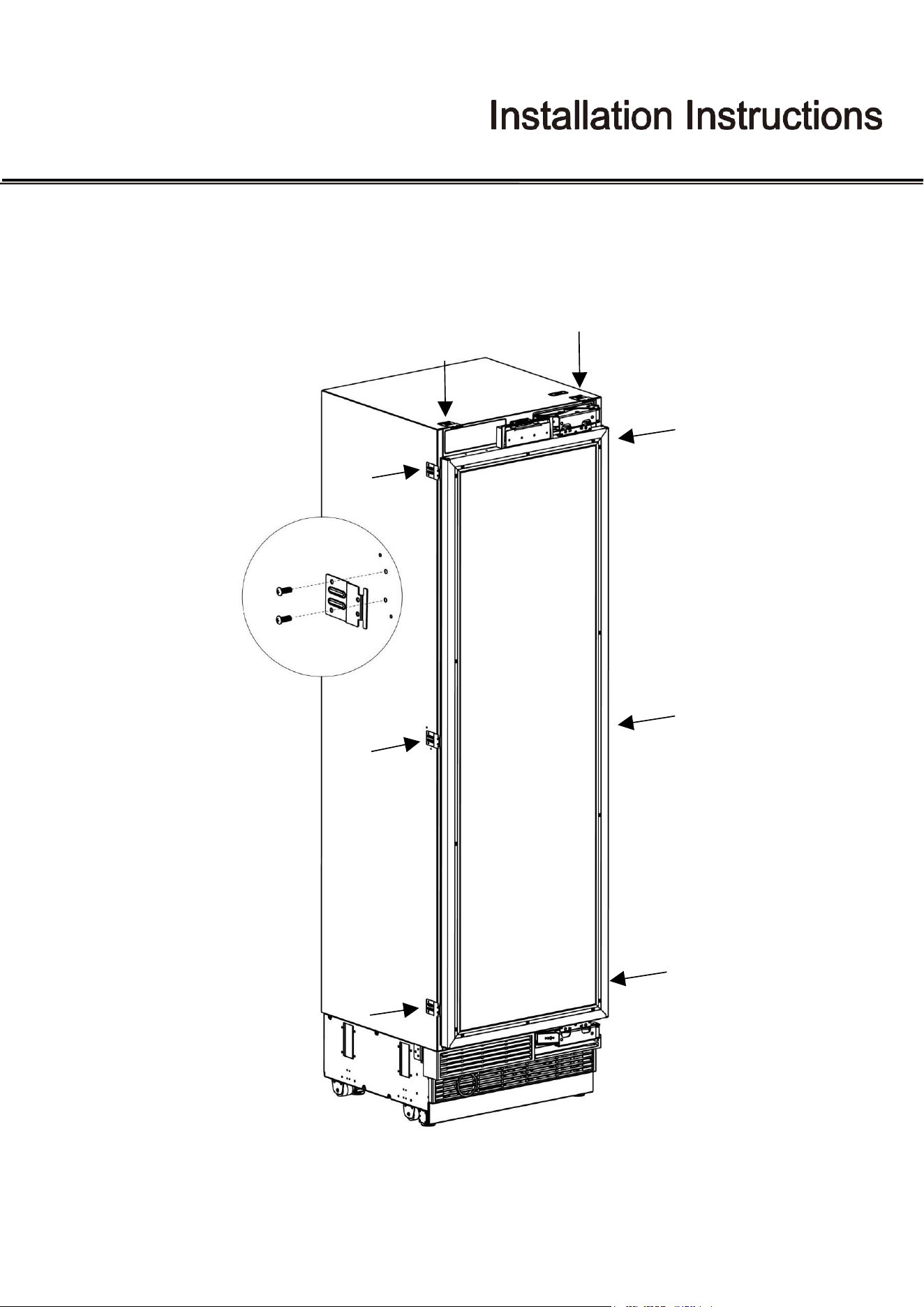
Screwing the side and upper brackets
● Fix the bracket furniture to the unit, where 2 on the top, and 3 on every side.
● Use the truss washer head screws(ST4*12) to tighten.
Use, Care, and Installation Guide
34
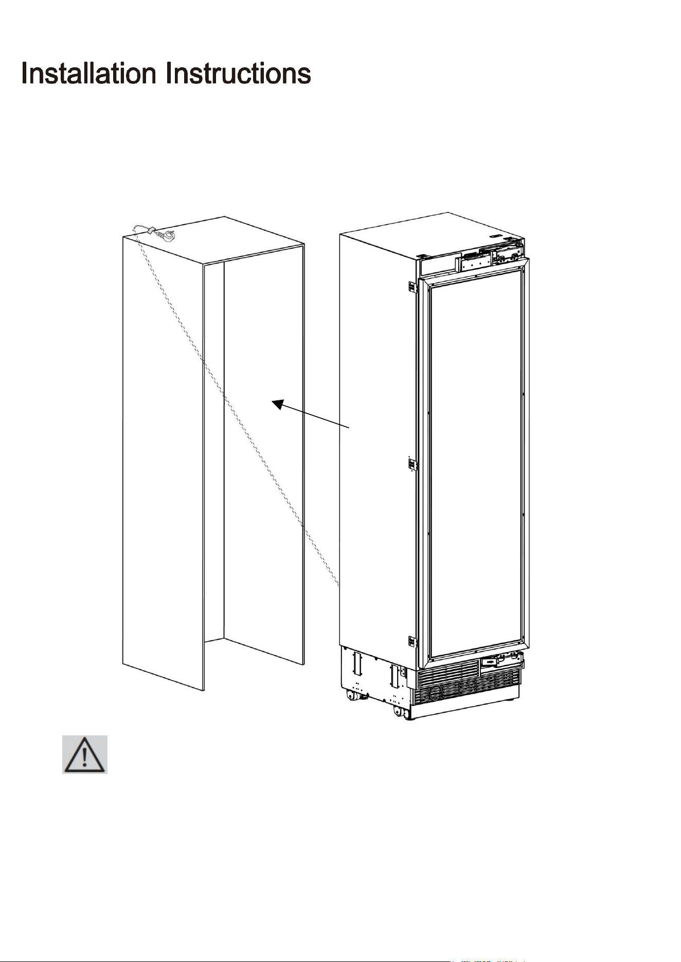
● Push the product carefully towards the cabin to place it.
The plug of the product must be accessible after installation.
Use, Care, and Installation Guide
Confidential
35
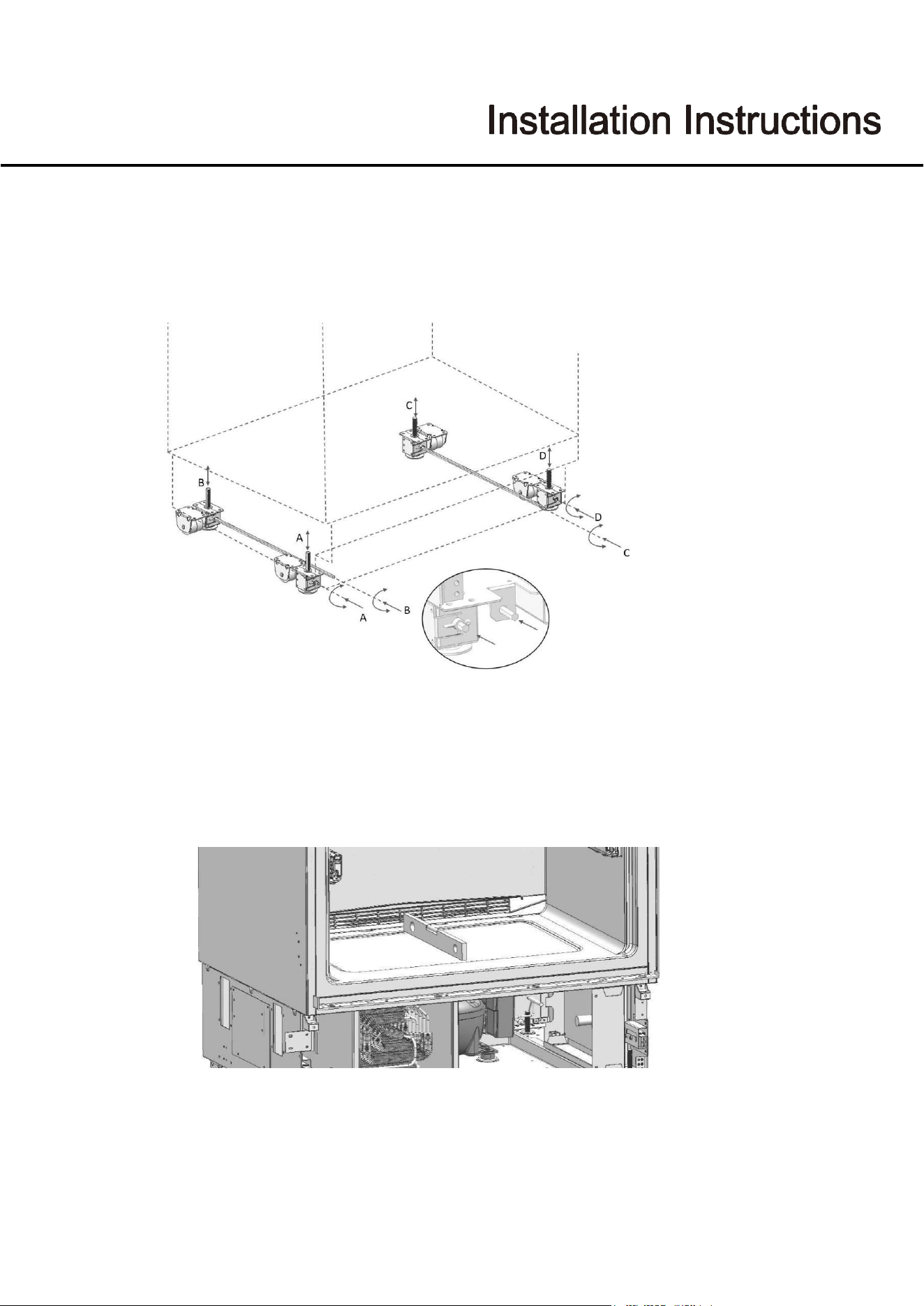
Adjusting the height of the wine cooler in the cabin
● Adjust the wine cooler height using the adjustable feet.
First of all, raise the front feet to reduce the risk of the cabin falling frontward.
A/D –Turn the key clockwise to lift the front
B/C –Turn the key clockwise to lift the rear
●
After adjusting the adjustable feet, check the flatness in both width and depth directions.
Use, Care, and Installation Guide
36
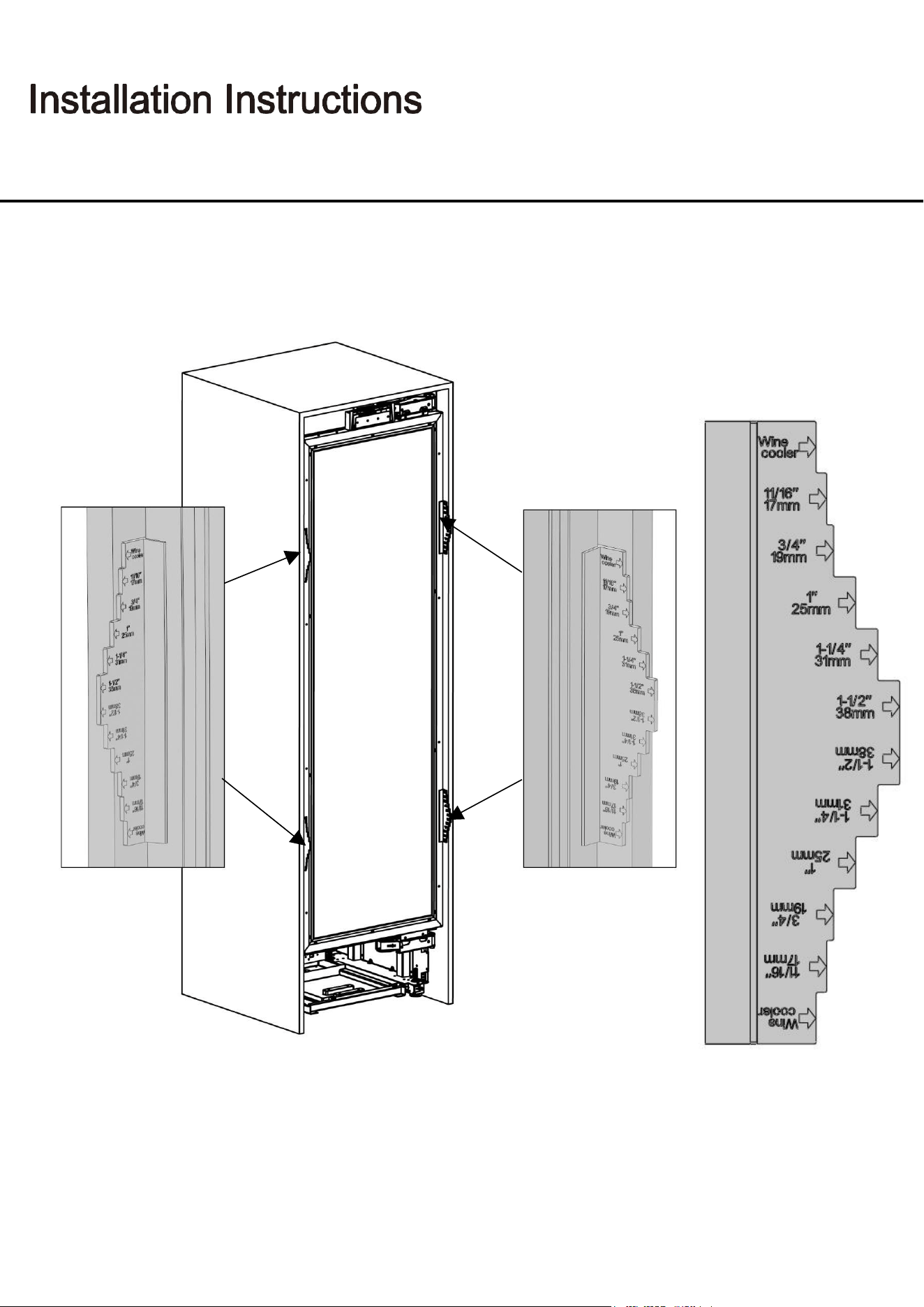
Adjusting the refrigerator according to the cabin flange
● Position of the level adjustment must be adjusted according to the thickness of the door.
Use, Care, and Installation Guide
Confidential
37
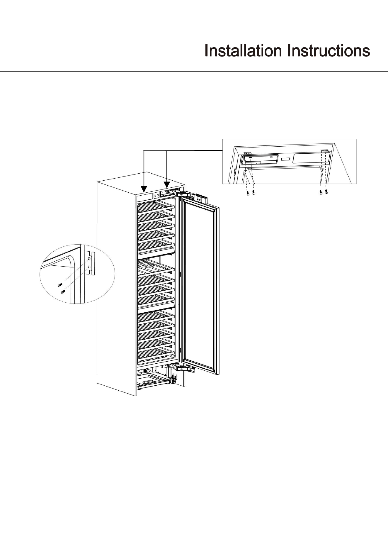
Screwing the side and upper brackets
● Attach the bracket furniture to the furniture with 16 screws(ST4x14).
Use, Care, and Installation Guide
38
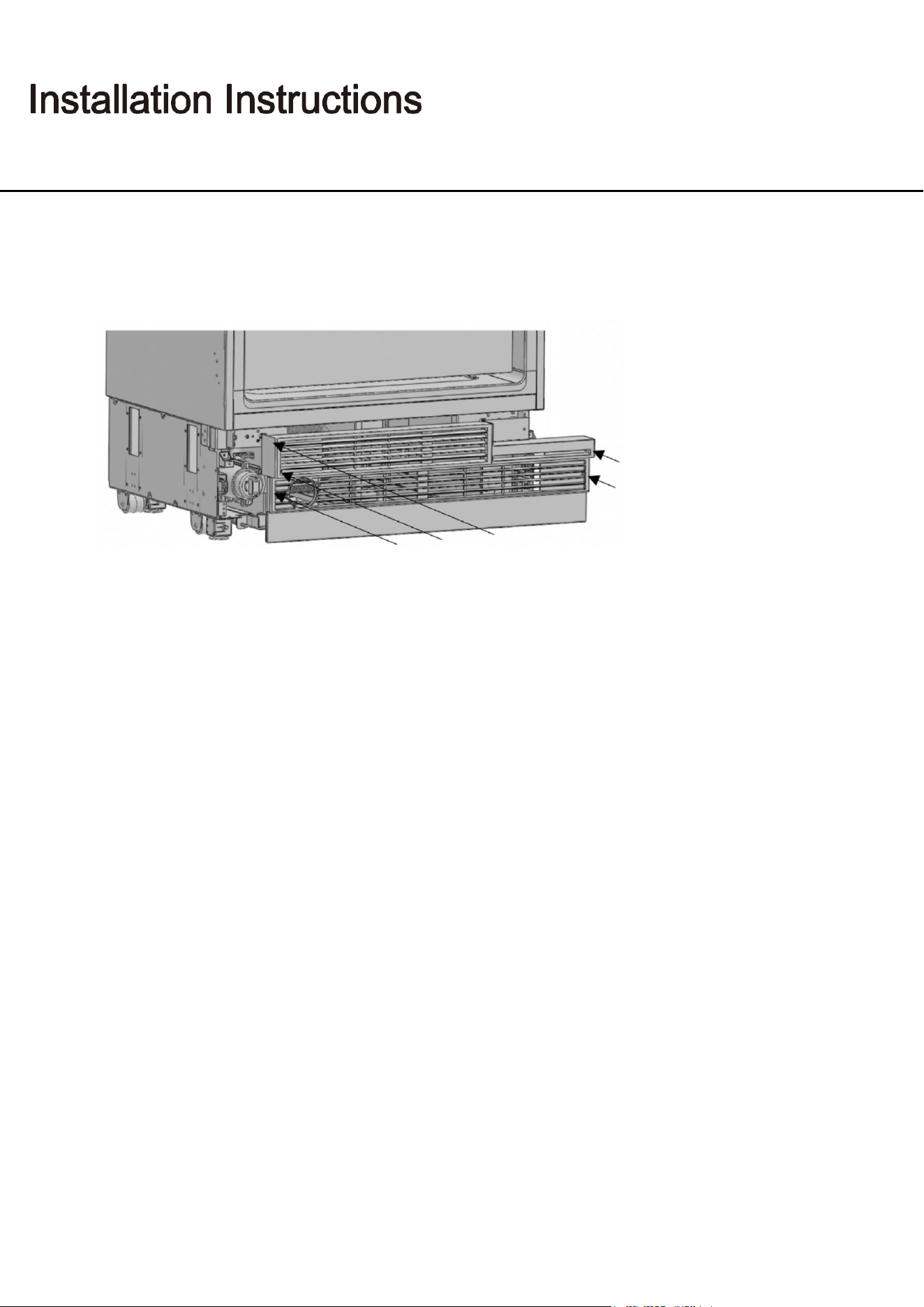
Attaching the vent hole assembly
● Use 5 screws to attach the vent hole assembly.
Use, Care, and Installation Guide
Confidential
39
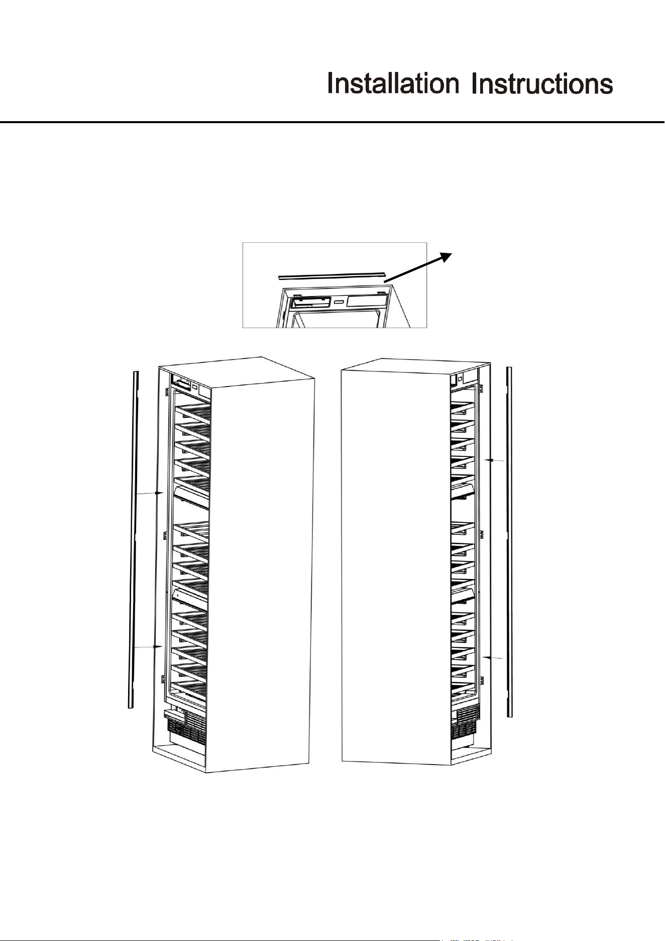
Attaching the decorative parts
● Attach the side closing parts onto the right/left/upper connection brackets.
2776mm
2766mm
UWFC18BNNPRY:457mm;
UWFC24BNNPRY:609mm
Use, Care, and Installation Guide
40
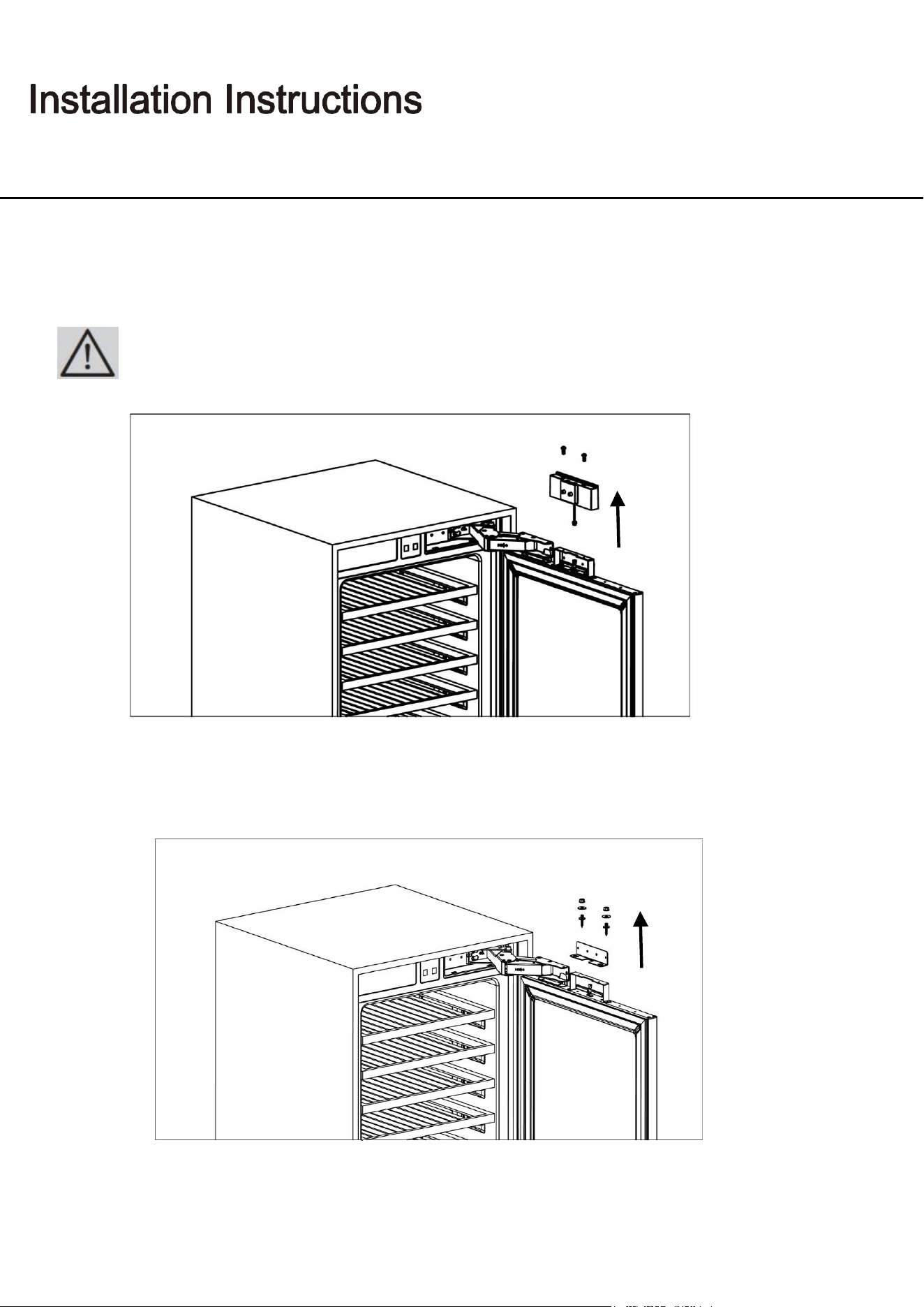
Removing the panel-adjustment mechanisms on the refrigerator
● Remove screws to take out the top hanger bracket cover.
● Remove the upper and lower adjusting mechanism assemblies from the door.
There is a magnet on the top hanger bracket cover. This is a functional part for the
operation of the product. It should not be confused with the low hanger bracket cover.
Use, Care, and Installation Guide
Confidential
41
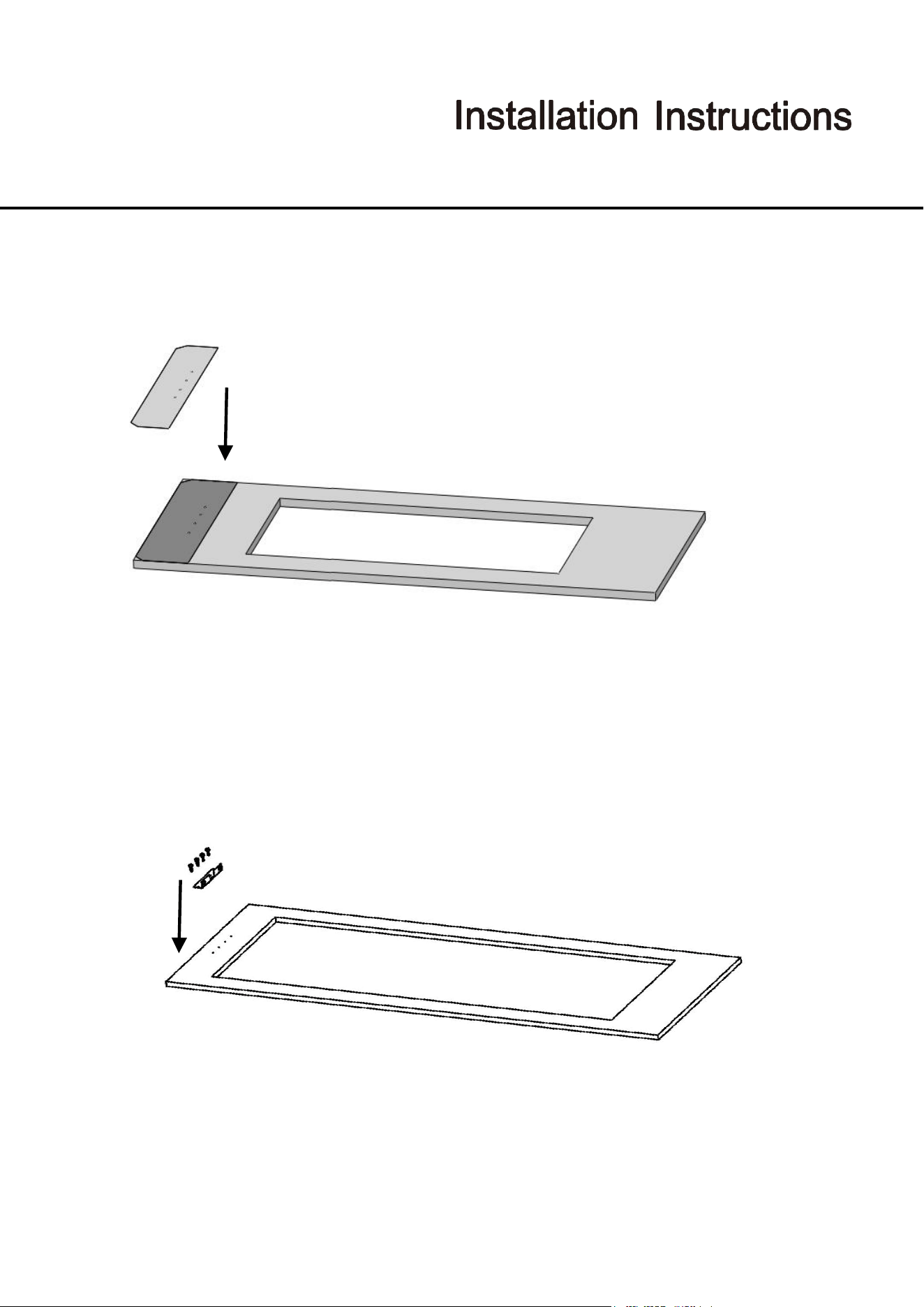
Preparing furniture door
● When marking, you can use the "Furniture door preparation template" provided with the product.
● Install cradles using the chipboard screws(ST4x14).
Use, Care, and Installation Guide
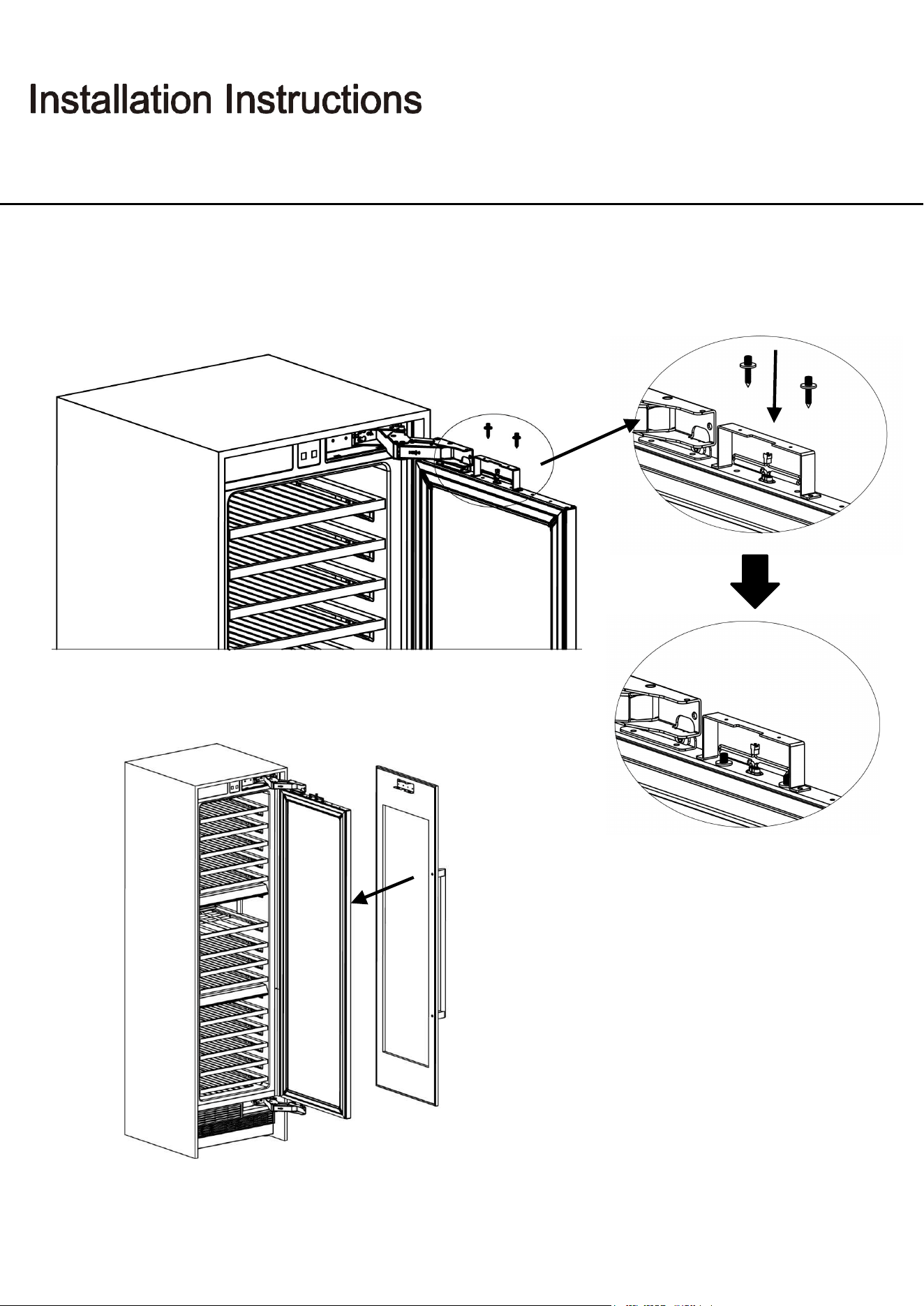
42
Installing the furniture door
● Use 2screws to fix.
● Attach the furniture door to the door
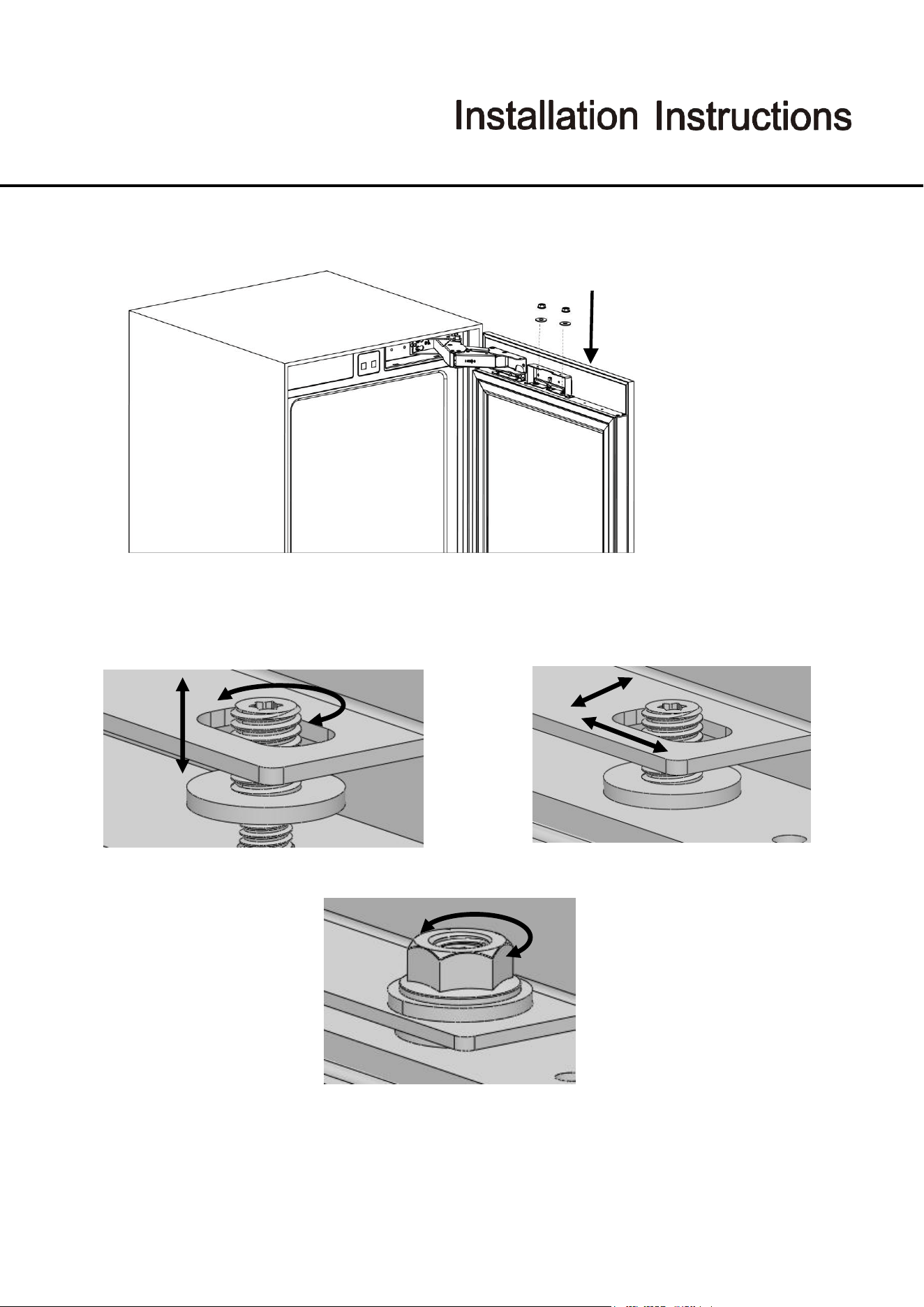
Use, Care, and Installation Guide
Confidential
43
● You should adjust 3D direction using by two fixing bolt to perform fine adjustments.
● How to align the furniture door upper part with bolts.
Front & back
Left & right
Fixing furniture door completely
Up & down
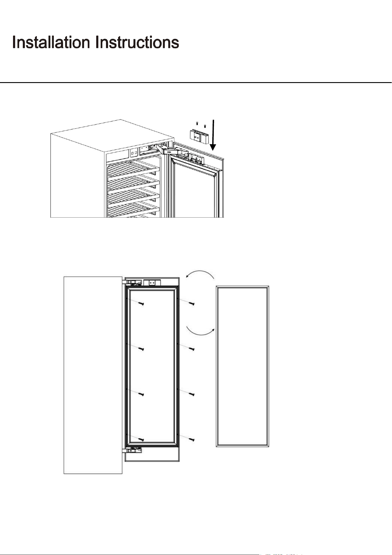
Use, Care, and Installation Guide
44
● Attach and screw the upper decoration cover.
●The left and right are secured by installing screws(ST4x35).
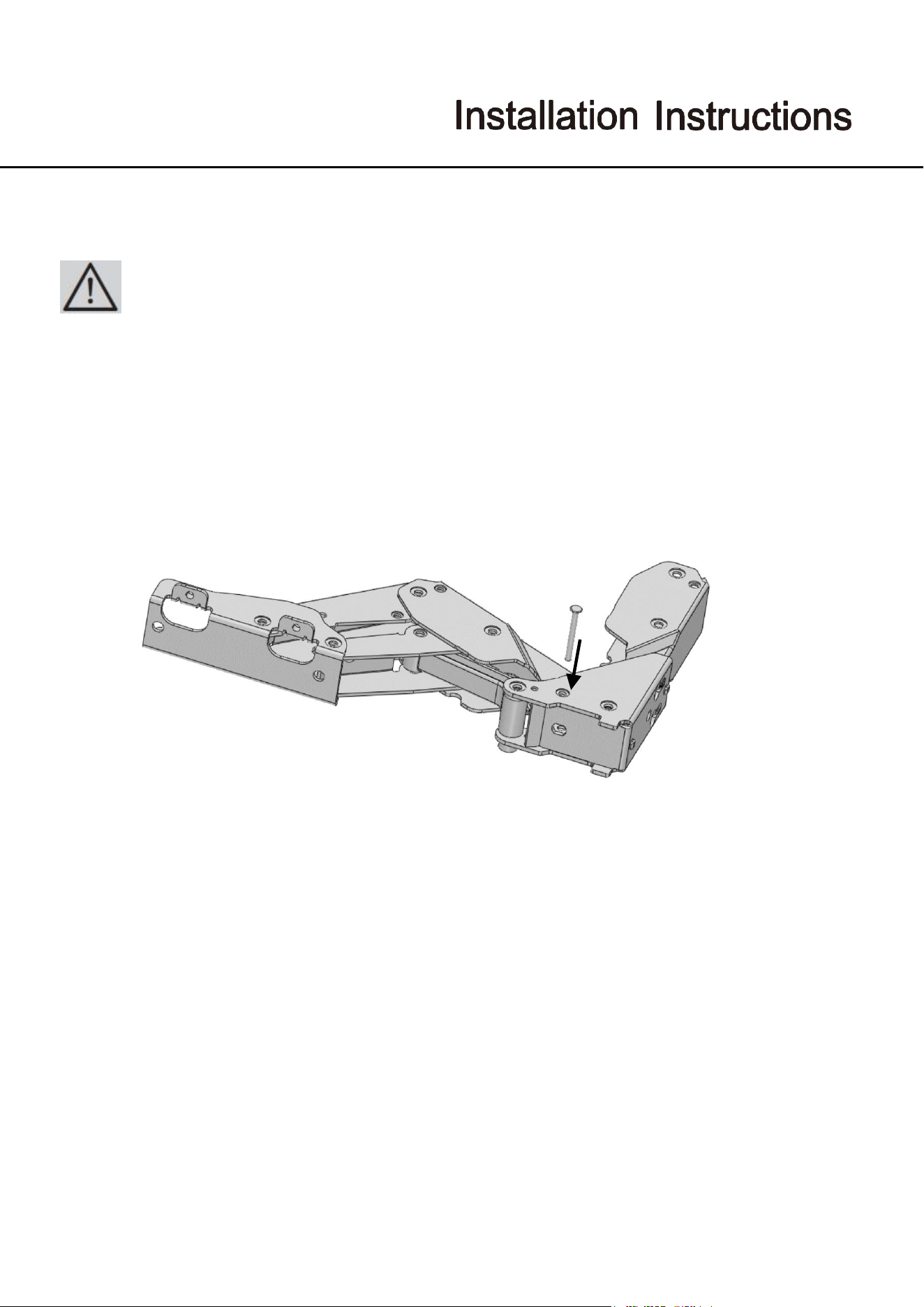
Use, Care, and Installation Guide
Confidential
45
Installing the limit pins
● limit pin should be inserted to upper hinge.
The door of your refrigerator can open by 115° maximum.
If the door thickness is more than 1 ½” (38 mm), the door should not open more than 90°.
You must use 90°limit pin on the hinge.
Pin must be fully seated in the bracket or the door will not close properly.
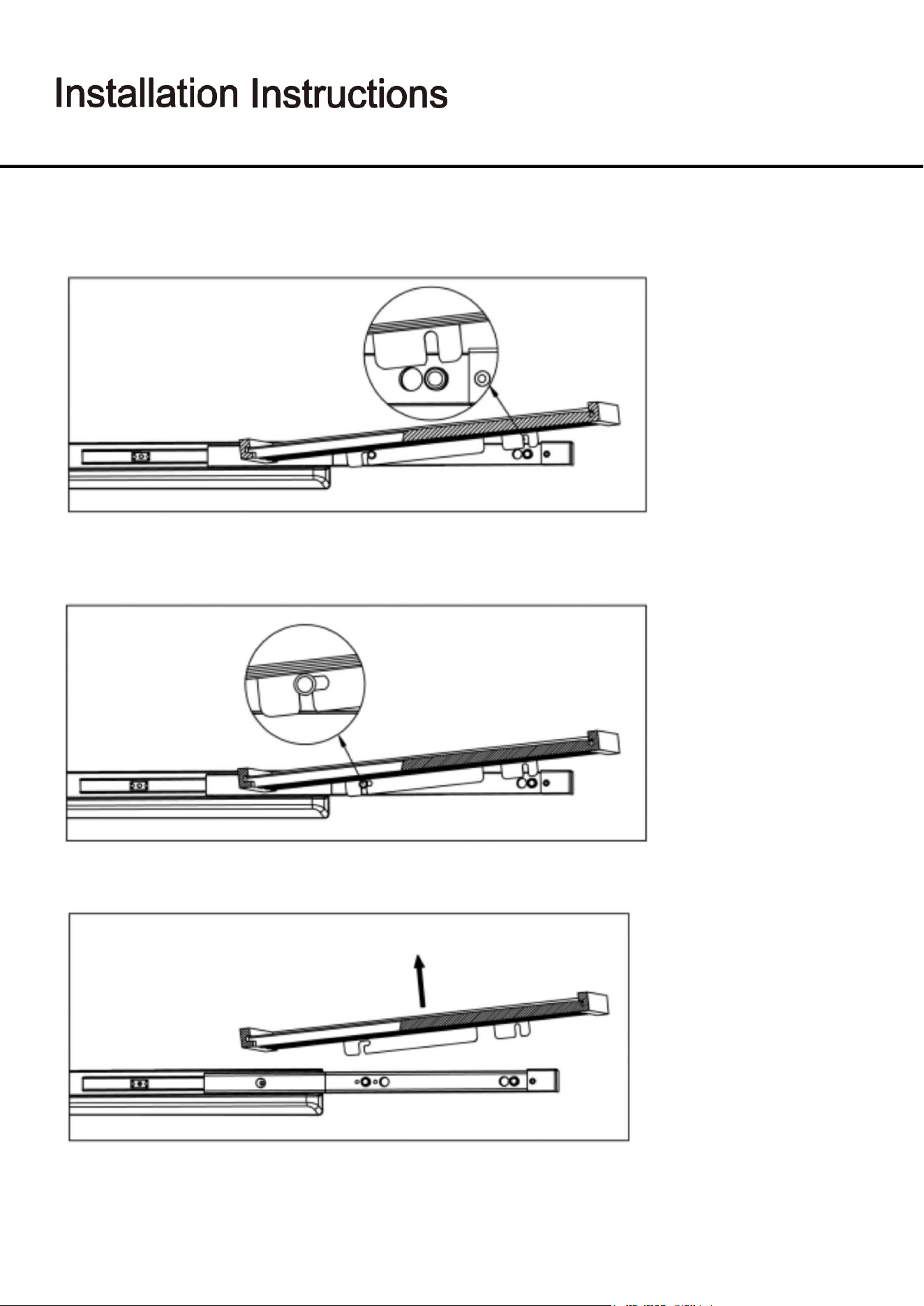
Use, Care, and Installation Guide
46
Removing the Wooden Shelves
1. Pull the wine rack. Wine rack card slot out of the guide rail fixed column.
2. Pull the wine rack forward. The guide retaining post is stuck in the position
indicated in the figure that the retaining.
3. Pull the wine rack to remove.
Use, Care, and Installation Guide
47
If the unit is unplugged, power lost, or turned off, you must wait 3 to 5 minutes before restarting the unit. If you attempt
to restart before this time delay, the appliance may not start and will not keep the last set temperature.
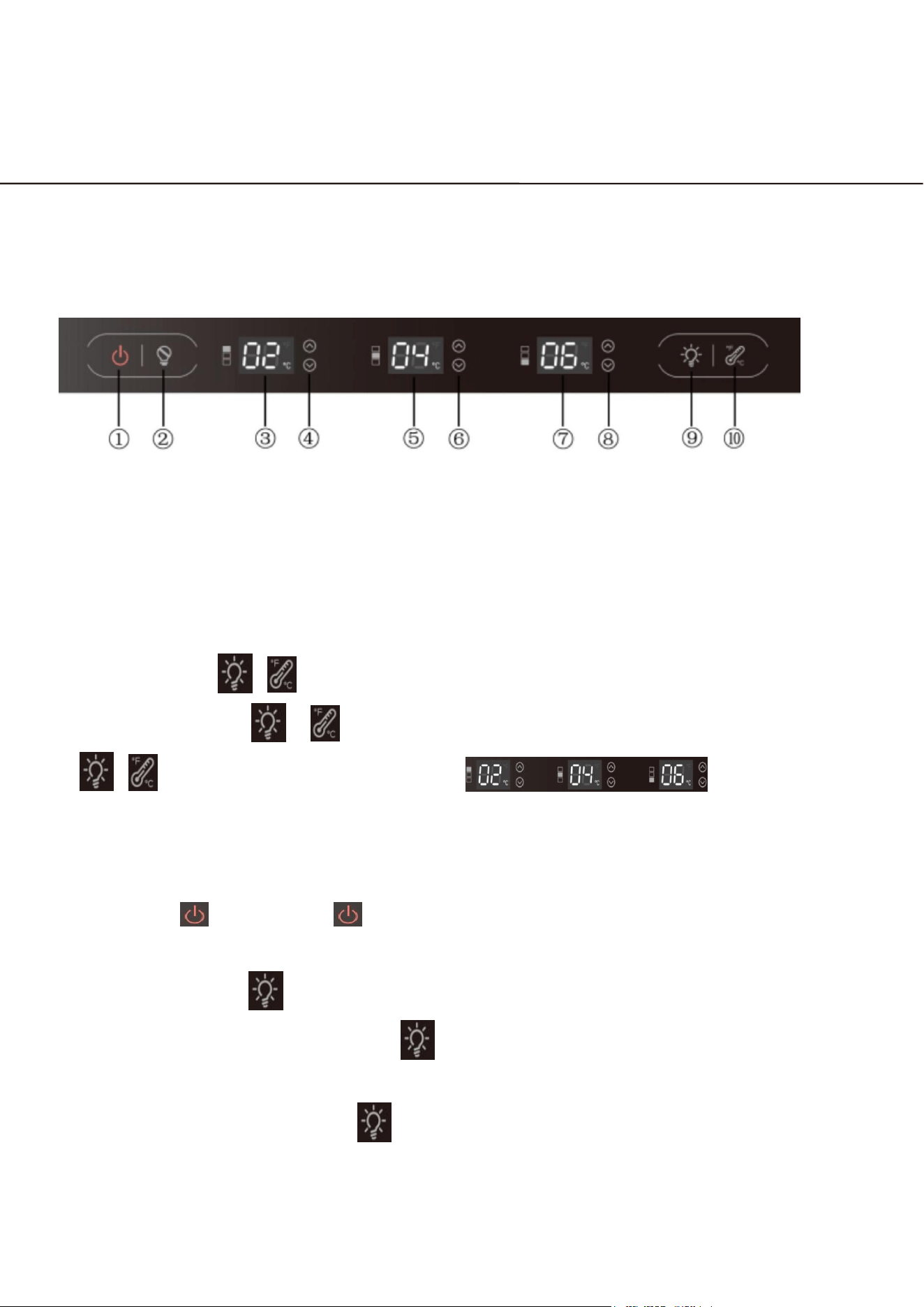
Using the Control Panel
① Power On/OFF ② Sabbath Mode
③ Upper Zone Temp ④ Above Zone Temp. Control
⑤ Middle Zone Temp ⑥ Middle Zone Temp. Control
⑦ Lower Zone Temp ⑧ below Zone Temp. Control
⑨ Light Switch
⑩ Temp. Display Change ℃←→℉
●
Child lock key ( + ): power on the default unlocked state; if you need to lock,
you need to press ( + ), manual locking, such as the need to unlock, press
( + ) to unlock; lock, press any key, the box within
the three temperature zones of the temperature value of the digital screen at the
same time blinking for 3 seconds, accompanied by beeping to suggest that in the
locking state;
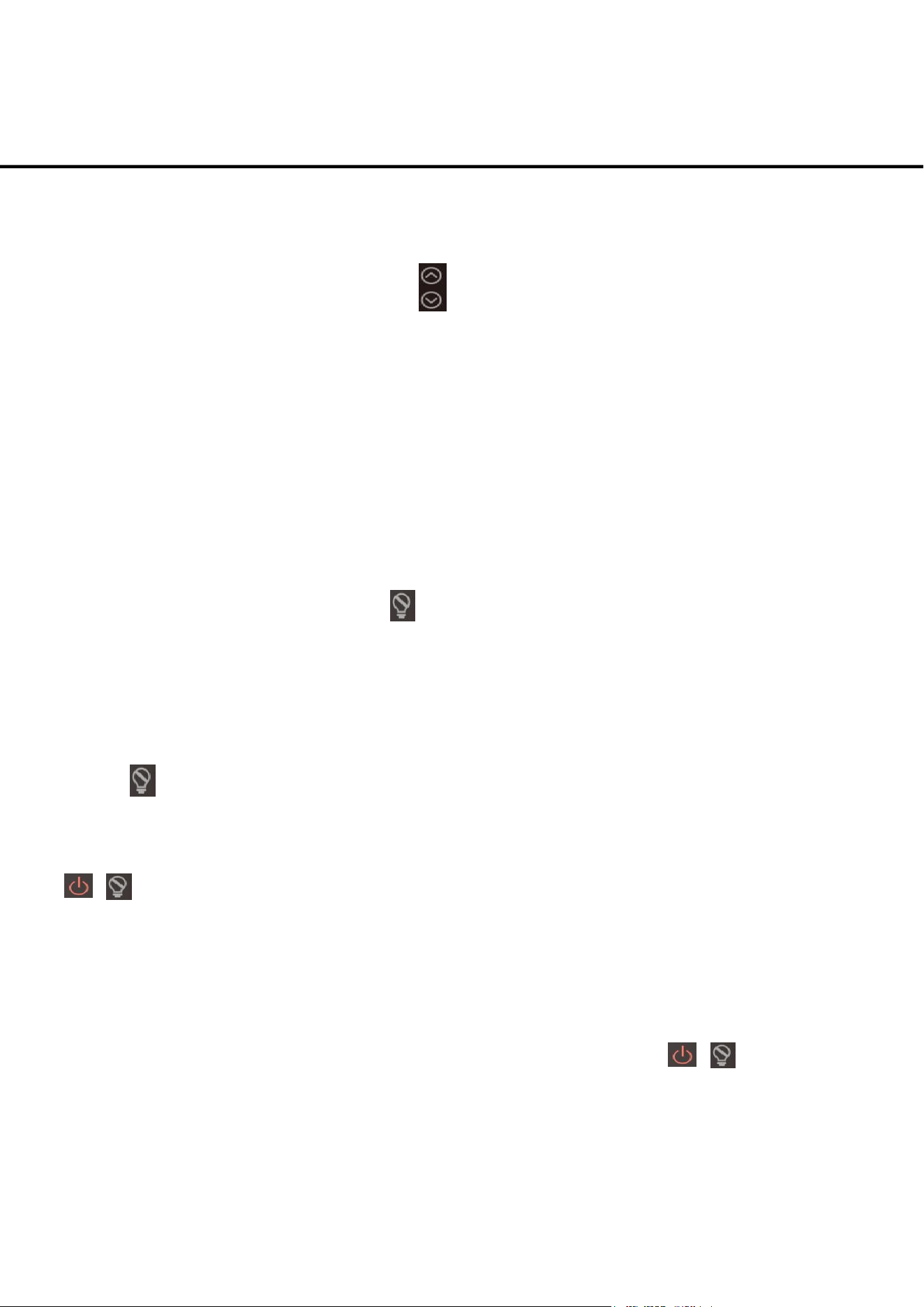
● On/Off key : Long press " " for 3s to turn on or turn off the power; when shutting
down, cut off the power of all peripherals and enter standby mode;
●
LED lighting button : LED lighting controlled by the door switch, open the door light,
Close the door light off; short press " " to realize the LED lighting red, blue, white,
off the light cycle between switching, memory of the last state (off the state of the light
is not memorized); long press " " 3 seconds to realize the light is always on, at the
same time,
Operating Your Appliance
Use, Care, and Installation Guide
48
the digital screen of the three temperature zones are displayed ON for 5 seconds,
5 seconds after the digital screen to restore the temperature value display; in the
digital screen display ON state, the key can be adjusted up and down to adjust
the brightness of the LED lighting, L1 ~ L7 cycle of adjustment, a total of 7 levels,
L7 is the brightest, the memory of the last time state;
● Open and close the door control: when the door is opened, the lighting is turned on,
the display is lit and kept until the door is closed, the fan stops, when the door is opened
for more than 5 minutes, the open door alarm is opened, and the alarm is canceled by
pressing any key; when the door is closed, the lighting is turned off (except for the manual
operation of the light), the fan stops the state of lifting and starting immediately, and the
door is closed for 30 seconds, and the display is turned off.
● Sabbath on/off key : Short press " " key to enter or exit Sabbath; after entering
Sabbath, the press and fan will run normally, the lighting will go out long time, the
display will go out long time, the buzzer will turn off, and the power failure will be
memorized, and the power failure will be automatically exited after 96 hours of
operation, and the failure will also be automatically exited; if you need to exit manually,
press " " key to exit the Sabbath mode, and after exiting, it will run in normal mode;he
● Show room mode: Enter the Showroom mode: Under the power off status, long press
( + ) key for 3 seconds, enter the Show room mode, and the display panel will have “SN”
word to indicate.
Under the showroom mode, the compressor will not work, meanwhile, other functions will
normally work. The showroom mode will not quit if power shut down, and the mode will
automatically quit after 72 hours.
Quit the Show room mode, under the power off status, press the ( + ) key again for 3
seconds, exit the Show room mode.
Operating Your Appliance
Use, Care, and Installation Guide
49
NOTE
When you change the temperature on the panel, the panel displays the current
temperature and the temperature on the display will gradually change according to
the internal temperature until it reaches the desired temperature. Note that it will take
time for the wine cellar to reach the new temperature. This is normal. You do not need
to set the desired temperature just because the display does not show your desired
temperature.
If the control panel has moisture or liquid on its surface, it may fail. Wipe the moisture
or liquid using a dry cloth, and then try again.
Power failure memory function
(after power-on, the Settings remain in the state before power failure)
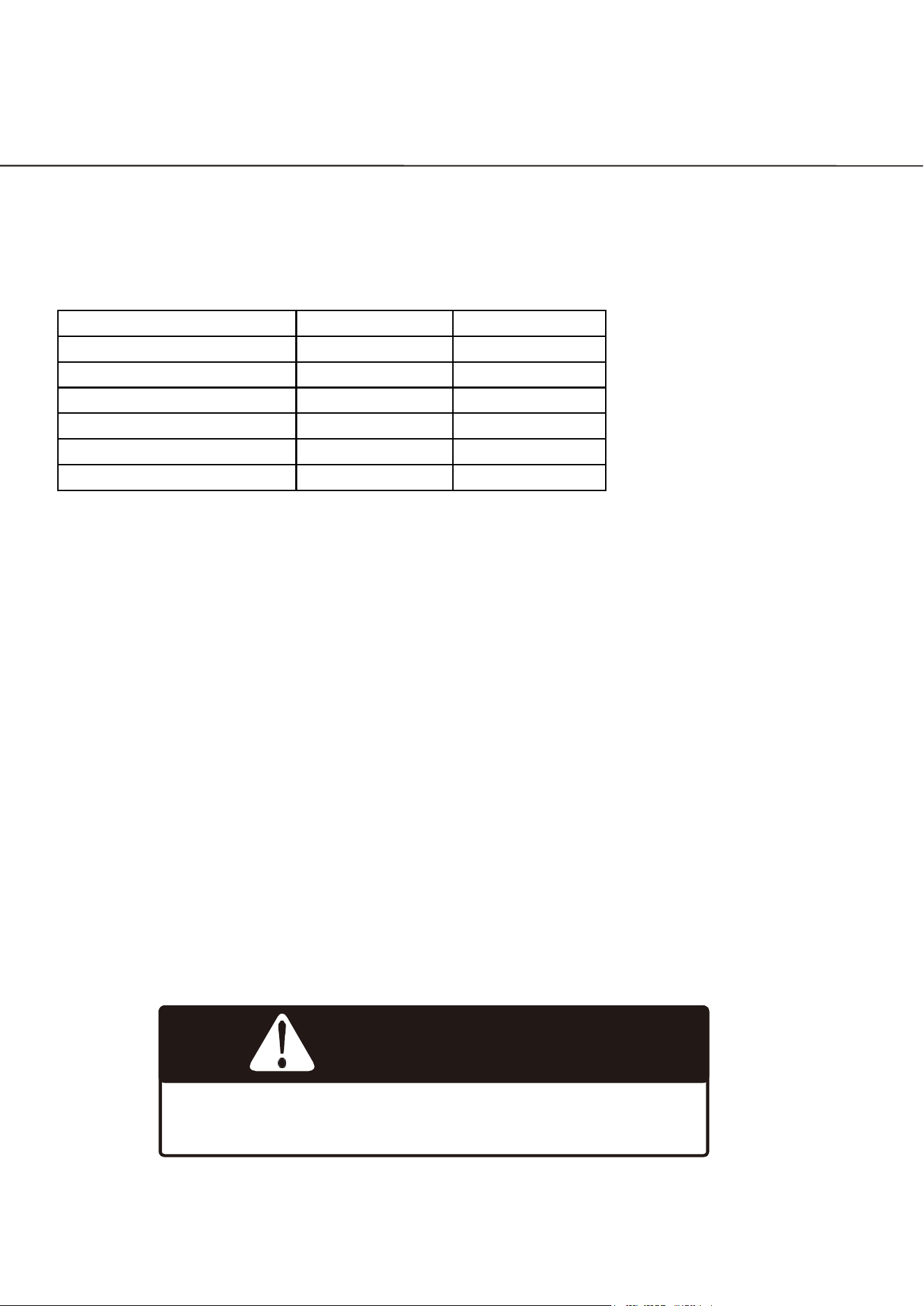
UPPER ZONE Temperature: 5-20℃(41°F - 68°F)
MIDDLE ZONE Temperature: 5-20℃(41°F - 68°F)
OWER ZONE Temperature: 5-20℃(41°F - 68°F)
Operating Your Appliance
Use, Care, and Installation Guide
50
WARNING
Do not puncture refrigerant tubing
Trouble Code
When a malfunction occurs, contact a service technician for repairs
Explanation
Open Circuit Code
Short Circuit Code
Above Zone In-cabinet probes
E1
E2
Above Zone Frosting probe
E3
E4
Middle Zone In-cabinet probe
E5
E6
Middle Zone Frosting probe
E7
E8
Above Zone In-cabinet probes
E9
E10
Below Zone Frosting probe
E11
E12
NOTE
1. When there is a fault code, the buzzer will emit "Tick" "Tick" "Tick" three consecutive
alarm sounds, the fault code flashes, every 10 seconds for a cycle, and the alarm will
be activated .if you want to release the alarm sound.
If you want to release the alarm sound, press the on/off key.
2. Whenever a key is pressed, the buzzer sounds "Tick".
Defrosting
The wine cooler is designed with an automatic defrost system. However, on colder settings, some
frost may build up. Additionally, the more humid the ambient conditions, the more frost may build up.
Keep the door closed as much as possible and avoid opening the door unnecessarily to minimize frost
build-up.
If frost is preventing the door from closing properly, you may need to power the unit off until the
frost melts (possibly up to 24 hours). Use a soft absorbent towel to dry the unit.
Operating Your Appliance
Use, Care, and Installation Guide
51
Normal Sounds
Your new wine cooler may make sounds that are not familiar to you. Most of the new sounds are
normal. Hard surfaces like the floor or walls can make the sounds seem louder than they actually are.
The following describes the kinds of sounds that might be new to you and what may be making them.
►
Rattling noises may come from the
fl
ow of the refrigerant or the water line.
►
Items stored on top of the wine cooler can also make noises.
►
The high efficiency compressor may make a pulsating or high-pitched sound.
►
Water running from the evaporator to the water bin may make a splashing sound.
►
As each cycle ends, you may hear a gurgling sound due to the refrigerant flowing in your
beverage cooler.
►
You may hear air being forced over the condenser by the condenser fan.
Cleaning the Unit
Periodic cleaning and proper maintenance will ensure efficiency, top performance, and long life.
Interior Cleaning
1.
Disconnect power to the unit.
2.
Open the door and remove the contents and shelves.
3.
With a clean cloth, wipe down the interior of the unit.
4.
Reinsert the shelves and beverages.
5.
Reconnect power to the unit.
Exterior Cleaning
The door and cabinet may be cleaned with a mild detergent and lukewarm water solution such as
two (2) tablespoons of baking soda to one (1) quart of water. Do not use solvent based or abrasive
cleaners. Use a soft sponge and rinse with clean water. Wipe with a soft clean towel to prevent water
spotting. If the door panel is stainless steel, it can discolor when exposed to chlorine gas and
moisture. Clean stainless steel with a cloth dampened with a mild detergent and warm water solution.
Never use an abrasive or caustic cleaning agent.
Care And Maintenance
Use, Care, and Installation Guide
52
Power Failure
Most power failures are corrected within a few hours and should not a
ff
ect the temperature of your
appliance if you minimize the number of times the door is opened. If the power is going to be o
ff
for a
longer period of time, you need to take the proper steps to protect your contents.
Moving Your Wine Cooler
►
Remove all items.
►
Securely tape down all loose items (shelves) inside your appliance.
►
Turn the adjustable leg all the way up (clockwise) to the base to avoid damage.
►
Tape the door shut.
►
Be sure the appliance stays secure in the upright position during transportation. Also protect
outside of appliance with a blanket, or similar item.
Energy Saving Tips
►
The appliance should be located in the coolest area of the room, away from heat producing
appliances, and out of the direct sunlight.
►
Ensure that the unit is adequately ventilated. Never cover air vents.
►
Only open the door for as long as necessary.
Care And Maintenance
Use, Care, and Installation Guide
53
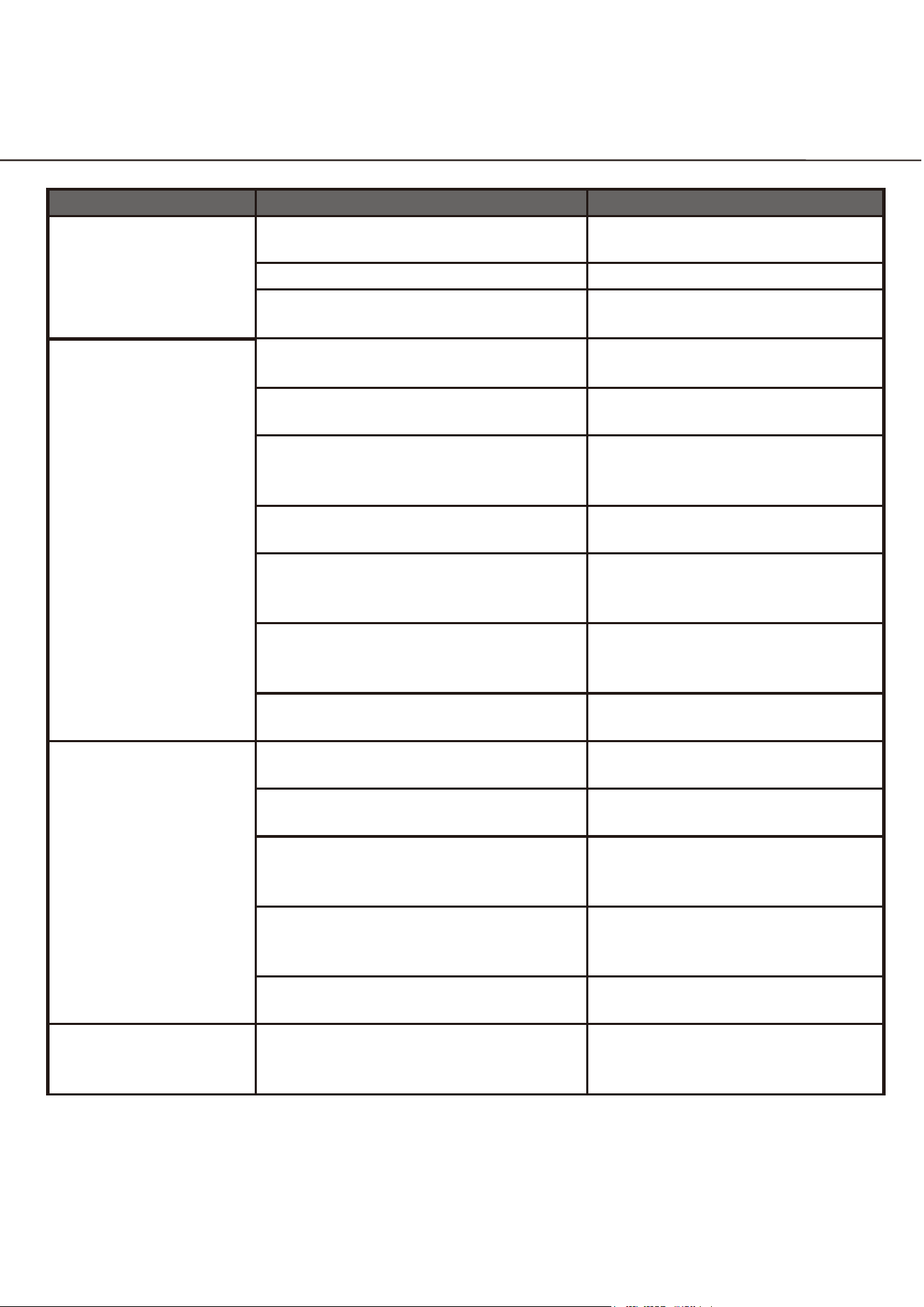
Possible Problem
Possible Cause
Solutions
The appliance does not
operate.
Not plugged in.
Ensure the appliance is plugged in
and the power outlet has power.
The appliance is turned o
ff
.
Turn on the appliance.
The circuit breaker tripped or has a
blown fuse.
Replace the broken fuse or reset
the breaker.
The appliance is not
cold enough.
Temperature control setting is too
high.
Adjust the set temperature.
External environment may require a
higher setting.
Keep the appliance away from
sunshine or other heat sources.
The door is opened too frequently or
for long periods of time.
Close the door tightly and do not
open the door too frequently or
for a long period of time.
The door gasket is not sealed properly.
Ensure the door gasket is not
loose.
Demonstration mode may be enabled.
See the Operating Your
Appliance section and verify if
Demonstration mode is disabled.
The cooler does not have su
ff
icient
ventilation.
Read and follow the “Installation
Clearance Requirements” in the
Installation Instructions section.
The cooler has restricted air flow due
to too much storage.
Open space in the cabinet to
allow air
fl
ow.
The appliance turns on
and off frequently.
The room temperature is hotter than
normal.
Run the refrigerator at the
appropriate ambient temperature.
The door gasket is not sealed properly.
Ensure the door gasket is not
loose.
The door is opened too frequently or
for long periods of time.
Close the door tightly and do not
open the door too frequently or
for a long period of time.
The cooler does not have su
ff
icient
ventilation.
Read and follow the “Installation
Clearance Requirements” in the
Installation Instructions section.
The door is not closed completely
Make sure the door is completely
closed.
The body of the
appliance is electri
fi
ed.
The unit is not properly grounded.
Contact your local electrician
to test your electrical grounding
system.
Troubleshooting
Use, Care, and Installation Guide
54
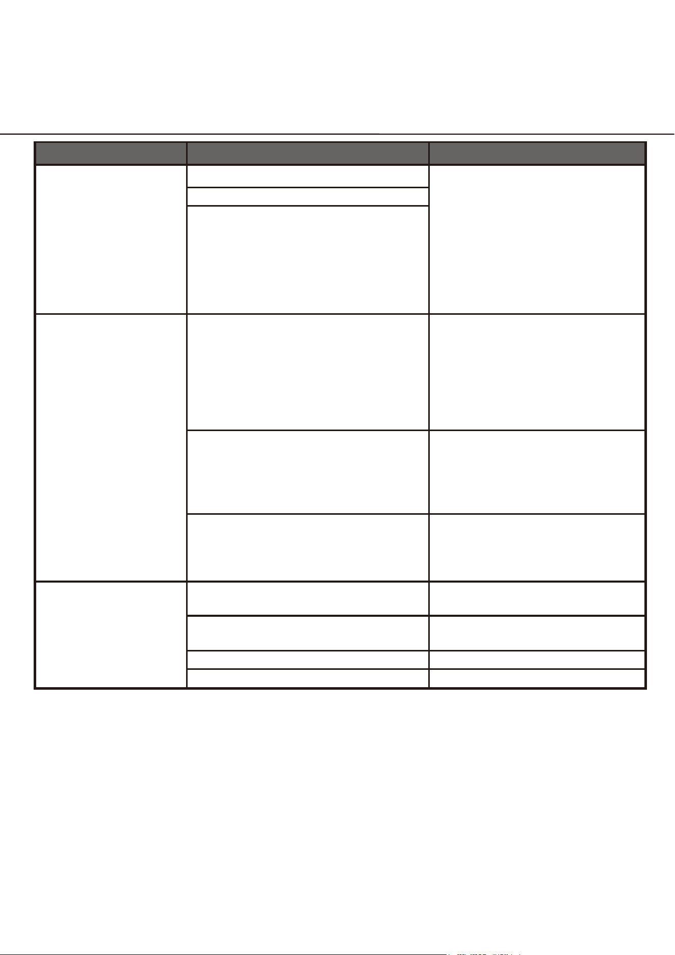
Possible Problem
Possible Cause
Solutions
Frost is forming in the
appliance.
The environment is too humid.
The unit uses an ‘auto-defrost’
system, under certain conditions,
manual defrosting may be
required. If frost builds up, you
can try running the refrigerator
on a warmer temperature setting,
minimizing the number of times
you open the door or unplugging
the unit to allow the frost to melt.
The ambient temperature is too low.
The door is being opened too
frequently.
The appliance makes
too much noise.
The rattling noise may come from
the
fl
ow of the refrigerant, which is
normal. As each cycle ends, you may
hear gurgling sounds caused by the
flow of refrigerant in the appliance.
It is normal that as each cooling
cycle ends, you may hearing
ratting or gurgling sounds caused
by the flow of refrigerant in the
appliance. The high efficiency
compressor may make a pulsating
or high pitched sound.
Contraction and expansion of the
inside walls may cause popping and
cracking noises.
Some popping or cracking noises
are normal. They are caused by
expansion and contraction of the
inside walls due to temperature
changes.
The unit is not level or is touching
another appliance.
Check to make sure the cooler is
level and that it is non in contact
with another appliance or
furniture.
The door will not close
properly.
The appliance is not level.
Make sure the appliance is on a
level surface.
The door gasket is not installed
correctly.
Make sure the door gasket is
properly installed.
The gasket is dirty.
Clean the door gasket.
The shelves are out of position.
Install the shelves correctly.
Troubleshooting

Ilve USA warrants to the original purchaser (“Purchaser”) of this product (the “Product”), for a period of two (2) years (except for
certain components identied below) from the date of original purchase, that the Product is free from defects in workmanship and
materials. This warranty covers all parts and labor required to repair or replace any part of the Product that proves to be defective
under normal residential use. To be eligible for this warranty, the Product must be: (i) sold to Purchaser as new products to the
original owner by an authorized distributor, retailer, dealer, or service center of ILVE USA and (ii) installed in the United States or
Canada. The warranties provided in this statement are not transferable and are valid from the date of purchase. Purchaser should
promptly register all purchased Products with ILVE USA in accordance with the written instructions accompanying the Product.
This limited warranty is valid only provided that written notication of a defect, as well as a copy of the original receipt for the defec-
tive Product including date of purchase, is received by Ilve USA from Purchaser within thirty (30) days of identication of the
defect. Ilve USA (who may appoint designees to act on its behalf in connection with any Product inspection or provision of warran-
ty services hereunder) reserves the right to inspect the Product and its installation. Purchaser providing Ilve USA with access to
the premises at which the Product is installed, and such other information and materials as Ilve USA may request, shall be a condi-
tion to any claim hereunder. If Ilve USA determines that a defect in the Product is covered by this limited warranty, it will, at its
expense and as its sole and exclusive obligation for breach of this limited warranty, and Purchaser’s sole and exclusive remedy,
repair or replace the defective Product. If Ilve USA determines that an alleged defect in the Product is not covered by this limited
warranty, it shall not have any obligation to repair or replace the Product. If Ilve USA agrees to undertake any repairs not covered
by this limited warranty, it will provide a quote to Purchaser to perform such repair work at Ilve USA’s then current rates.
ILVE USA will initially attempt to repair any defect Products. Only if a Product cannot be repaired by an ILVE USA authorized local
service provider may the Product be replaced with a new Product from ILVE USA. In the event Ilve USA determines that a defective
Product must be replaced, the Manufacturer will be contacted to process a replacement order. In the event that Ilve USA deter-
mines a Product is irreparable, replacement approval form the Manufacturer may take up to 30 days. For instances where a Prod-
uct is installed in a remote area outside of an ILVE USAs authorized locate service provider’s territory, Purchaser is responsible for
all delivery costs and risk of loss associated with transportation of the Product to the nearest Ilve USA authorized service center or
for the travel and associated out-of-pocket costs of an ILVE USA authorized service provider to travel to Purchaser’s location to
provide warranty services.
A Purchaser who chooses to install eligible products itself must establish that it has done so in accordance with all directions and
installation instructions included with the Product’s accompanying materials at time of purchase. Ilve USA shall have no obligation
to render any services to correct issues caused by a Purchaser’s failure to follow all directions and instructions. If Ilve USA agrees
to undertake any such services, it will provide a quote to Purchaser to perform such services at Ilve USA’s then current rates.
A Products’ exterior paint and/or lacquer must be cared for according to the instructional materials provided with the Product at
time of Purchaser. If those instruc¬tional materials are not followed or harsh chemicals are used, any damages and subsequent
repairs to a Product’s paint and/or lacquer are not covered by this warranty.
Eective March 1st, 2024
Thank you for choosing an ILVE USA appliance for your home.
TWO Year Limited Warranty
1/2

Component Warranty Periods:
Any components of eligible products showing cosmetic defects, whether in material or workmanship, are covered by this warran-
ty for a period of thirty (30) days from the product’s delivery date. Coverage* is provided for:
• Scratches
• Stains
• Surface Imperfections (ONLY stainless steel)
• Paint & Porcelain Imperfections
* Excludes slight dierences in color due to materials and painting/enameling technologies. Photo/video proof required.
Gaskets are covered by this warranty for a period of ninety (90) days from the product’s installation date. Replacement of glass
components and light bulbs are covered by this warranty for a period of thirty (30) days aer delivery.
Exclusions to Warranty Coverage: This Limited Warranty will not apply to any of the following:
• Any service, including repair service to correct damage caused by services, performed on the Product by anyone other than
an authorized ILVE USA service provider, or the use of parts not authorized by Ilve USA..
• Defects or damage caused by improper storage, cleaning and maintenance of the Product, including any failure to comply
with Manufacturer’s written instructions and documentation regarding same
• Service calls to connect, convert, or otherwise repair the electrical wiring and/or gas line to properly use the Product
• Replacement of components prone to wear and tear
• Defects and damages arising from transportation of the Product to the home of the owner, by the dealer/retailer
• Defects and damage arising from external forces beyond the control of ILVE such as re, ood, earthquakes, and other acts
of God
• Accidental or intentional damage.
• Use of improper pans, containers, or accessories that cause damage to the Product.
Warranty Void: This Limited Warranty will be void in any of the following circumstances:
• The Product is used on a commercial, rental, or leased basis
• The serial plate for the Product is defaced
• The Product is altered by anyone other than an authorized ILVE USA service provider
• The Product is not used according to Manufacturer’s written instructions and documentation regarding same.
THE REMEDIES DESCRIBED ABOVE FOR EACH WARRANTY ARE THE ONLY ONES THAT ILVE USA WILL PROVIDE, EITHER UNDER THIS WARRANTY OR
UNDER ANY WARRANTY ARISING BY OPERATION OF LAW. ILVE USA WILL NOT BE RESPONSIBLE FOR ANY CONSEQUENTIAL OR INCIDENTAL DAMAGES
ARISING FROM THE BREACH OF THIS WARRANTY OR ANY OTHER WARRANTY, WHETHER EXPRESS, IMPLIED OR STATUTORY
This warranty gives you specic legal rights and you may have others which vary from state to state.
PHONE: (201) 228-9415
ILVEWARRANTY.COM
48 W 20th St, New York NY 10011
2/2