
Life Sensing Instruments, Inc. | CONFIDENTIAL Pg. 1
AXISO
2
TRANSMITTER
Operator’s Manual
Life Sensing Instruments, Inc.
December 16, 2025

Life Sensing Instruments, Inc. | CONFIDENTIAL Pg. 2
AxisO
2
Transmitter Overview
The AxisO
2
Transmitter is a component of a wireless medical patient-monitoring system designed to acquire and
transmit electrocardiogram (ECG) and pulse oximetry (SpO
2
) data to a telemetry receiver. The receiver forwards
the data to a central monitoring station for display, trending, and analysis by healthcare professionals.
The AxisO
2
uses four patient lead wires connected to disposable ECG electrodes to derive three ECG channels.
The analog ECG signals are digitized, processed, and transmitted wirelessly using the Wireless Medical Telemetry
Service (WMTS) frequency bands.
In addition to ECG, the AxisO
2
supports pulse oximetry monitoring through an external Nonin XPOD module. The
XPOD collects photoplethysmography (PPG) data via a compatible Nonin sensor and communicates the calculated
SpO₂ and pulse rate values digitally to the AxisO
2
.
AxisO
2
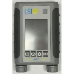
Keypad/Buttons
The keypad provides a protective cover for the LCD, contains the assigned TrensCenter Channel Number, and has
(4) buttons:
• POWER BUTTON:
o This button has a dual functionality – the button is used for powering the transmitter and displays
high-level status information.
o Power Functionality: Press and hold the button for (2) seconds to power on or off the transmitter.
The transmitter will make an audible beep to indicate the transmitter is powering on or off.
o Status Functionality: When the PMT is powered on, the Power Button will be illuminated with
different colors to indicate the transmitter’s status:
Orange: Transmitter is powered on without an active communication link with the Nexus
Telemetry Receiver. To resolve, ensure that the transmitter is in the pre-defined wireless
range and confirm that the Nexus Telemetry Receiver is powered on.
Purple: Transmitter is powered on with an active communication link with the Nexus
Telemetry Receiver.
Blue: Transmitter is powered on with an active communication link with the Nexus
Telemetry Receiver, and the transmitter has been admitted to TrensCenter software.
Red: Transmitter has reached a state of low battery. Replace batteries to resolve.
o Main Screen Functionality: Press this button to navigate to the Main Screen. Note: The Main
Screen only displays when the Transmitter is admitted to TrensCenter.
• VIEW BUTTON:
o Lead Off Functionality: Press this button to navigate to the View Screen which displays the
connection status of each ECG electrode. A Green Checkmark indicates that the electrode is
connected. A Red X indicates that the electrode is disconnected. Note: This button only has
functionality when the transmitter is admitted to TrensCenter.
• STATUS BUTTON:
o This button is used to access the Status Screen for support purposes.
• REMOTE RECORD BUTTON:
o Press and hold this button for (1) second to store a “Remote” Event in TrensCenter. Note: This
button only has functionality when the transmitter is admitted to TrensCenter.
AxisO
2
Display Overview
The display has three modes of operation that are designed to maximize battery life.
• Active Mode: The LCD is turned on and at full brightness. This mode is initiated when the keypad buttons
are pressed, or the transmitter is powered on. Active Mode uses the most current and impacts battery life.
• Inactive Mode: The LCD is turned on but has dimmed the brightness level due to inactivity.
• Sleep Mode: The LCD is turned off due to inactivity. Sleep Mode uses the least amount of current and
increases battery life.
The display is configured to display Status Indicators at the top of all screens. Examples of Status Indicators
include Channel Number, Filter/Monitor, Pacer, Remote Record, Primary/Auxiliary, Battery Strength, and Signal
Strength.
Life Sensing Instruments, Inc. | CONFIDENTIAL Pg. 3
The Main Screen displays the patient’s Heart Rate, SpO
2
%, and Pulse Rate (as determined and reported by
TrensCenter) and the patient’s configured Target Heart Rate Range.
Instructions for Use
Insert the Batteries
Unscrew each battery cap by grasping the battery cap and turning it counterclockwise until the cap has been full
removed. Insert (2) AAA batteries into each battery well following the battery direction indicator on the back of the
transmitter. Repeat the above instructions for the battery caps but rotate the battery cap clockwise to tighten.
CAUTION: MAKE SURE THE BATTERIES ARE INSTALLED CORRECTLY. IF THE BATTERIES ARE INSTALLED
INCORRECTLY, THE TRANSMITTER WILL NOT FUNCTION.
CAUTION: MAKE SURE THAT THE BATTERY CAP IS TIGHT. IF THE CAP IS NOT TIGHTENED PROPERLY,
THE TRANSMITTER SIGNAL MAY BE INTERMITTENT, AND THE WATERPROOFING SEAL MAY NOT SEAL
WHICH MAY DAMAGE TO THE TRANSMITTER.
Power on the Transmitter
Press and hold the button for (2) seconds to power on or off the transmitter. The transmitter will make an audible
beep to indicate the transmitter is powering on or off. The Power Button’s LED will flash Purple to indicate the
transmitter has a communication link with the Nexus Telemetry Receiver.
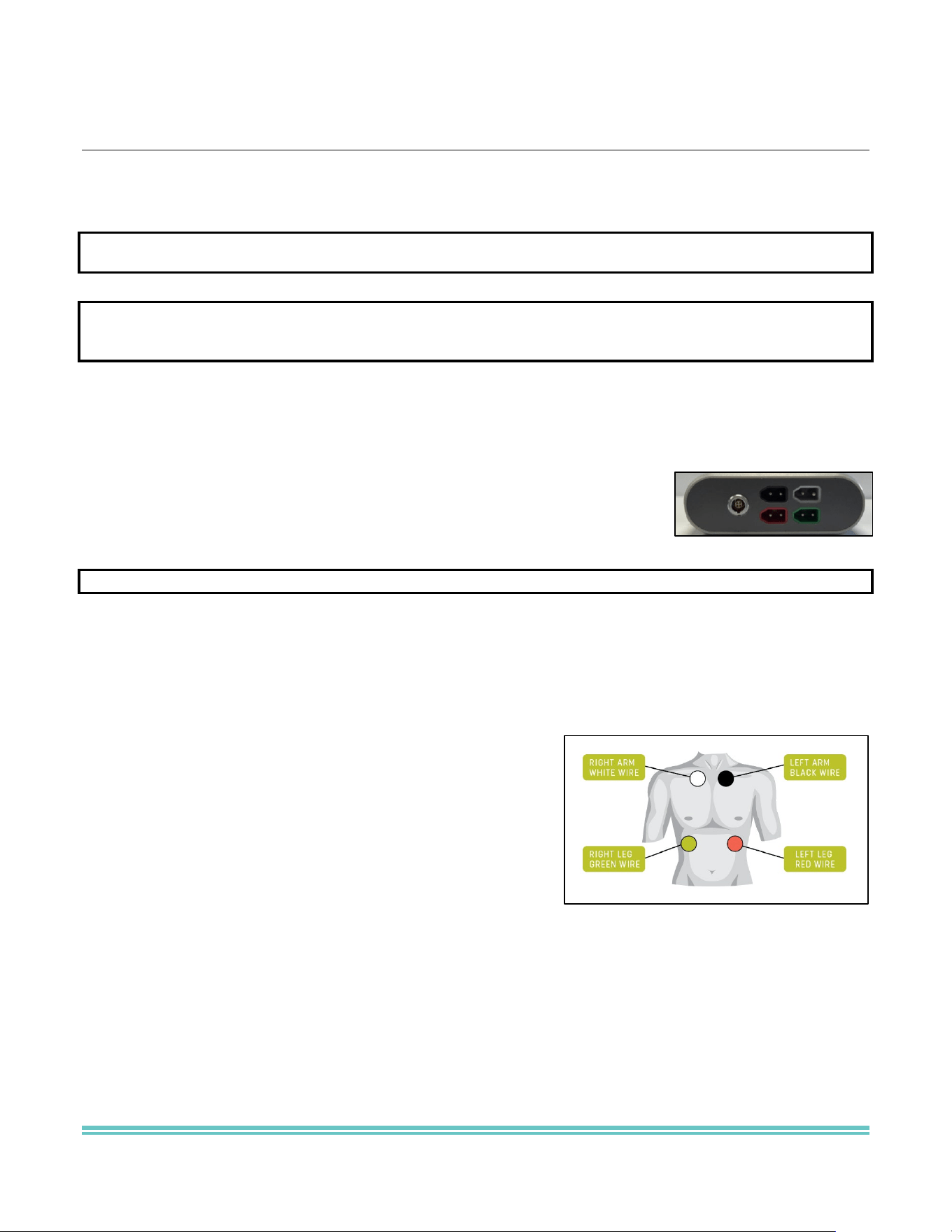
Connect the Lead Wires & Electrodes
The patient lead wires have a color-coded connector that plugs into a
corresponding color-coded transmitter connector. When inserting the lead wires,
insert the connector until the cables fit firmly into the transmitter.
CAUTION: ONLY USE THE LEAD WIRES SUPPLIED BY LSI FOR OPTIMAL PERFORMANCE.
Gently abrade the electrode sites with an alcohol prep pad until slight redness is observed. Dry the site before
applying the electrodes. Attach the electrodes to the patient on the prepared sites. Apply pressure to the outer
edges of the electrode, not the center. Applying pressure to the center may cause the electrode conductive jelly to
ooze out, resulting in a loose electrode. Attach the electrodes to the lead wires.
For optimum monitoring, the electrodes should be placed in the following locations:
• WHITE (Right Arm): Right Clavicle and Right Sternal
Border in the interclavicular notch
• RED (Left Leg): Lower Left Rib Cage, at the V6 chest lead
position
• BLACK (Left Arm): Left Clavicle and Left Sternal Border in
the interclavicular notch
• GREEN (Right Leg): Grounding electrode, Lower Right Rib
Cage
Verify Electrode Placement
Admit the patient in TrensCenter to the designated Channel. Confirm that the waveform is accurate. Adjust
electrodes as necessary to optimize waveform display.
Connect the SpO
2
Sensor
The SpO
2
sensor has a barrel jack “male” connector that plugs into a corresponding circular connector. When
inserting the “male” connector, confirm that the red dot on both connectors is aligned.
Remote Record Button
Press and hold the Remote Record Button for (1) second to store a “Remote” Event in TrensCenter.

Life Sensing Instruments, Inc. | CONFIDENTIAL Pg. 4
Battery Life Indicator
The Battery Life Indicator on the LCD displays the approximate remaining battery capacity. The icon uses a
segmented battery graphic – two white cells indicate maximum battery life, while one yellow cell indicates
approximately 50% remaining. When the battery level reaches a critical threshold, the battery icon turns red and
the power button begins flashing red. This low-battery alert provides at least 15 minutes of warning before the
transmitter powers down automatically.
Signal Strength Indicator
The Signal Strength Indicator located on the LCD displays the quality of the wireless connection between the AxisO
2
transmitter and the Nexus Telemetry Receiver. The icon uses four bars to represent signal strength – four bars
indicate an ideal connection, while a single red dot indicates the weakest signal. If the indicator shows low strength,
move the transmitter closer to the ceiling-mount antenna or ensure there are no obstructions between the
transmitter and the ceiling-mount antenna.
Support Services
The authorized support provider for the AxisO
2
Transmitter is Life Systems International (LSI), located in Charlotte,
NC. Support services include hardware support available through the Repair Depot. To learn more about the
support services offered by LSI, call 800-846-1279 x1.
Repair Depot
For repair services of the AxisO
2
Transmitter, contact the authorized support provider:
LSI
Attn: Repair Depot
2102 Cambridge Beltway Dr., Ste. A
Charlotte, NC 28273
800-846-1279 x1
support@lsi-medical.com
AxisO
2
Transmitter Specifications
MECHANICAL
PHYSICAL DIMENSIONS (WxHxD) 2.9" W x 4.2" H x .9" D
WEIGHT (WITHOUT BATTERIES 5.4 oz
WEIGHT (WITH BATTERIES, CABLES) 10.9 oz
BATTERY COMPARTMENT 2 COMPARTMENTS, POLARITY PROTECTED
DATA
ECG SAMPLE RATE 256/SECOND
SPO2 SAMPLE RATE 37.5/SECOND
ELECTRICAL
BATTERY TYPE (4) AAA BATTERIES
INPUT VOLTAGE 2.4 – 6.0 VDC (4 x AAA BATTERIES)
RUN TIME (W/CONTINIOUS SPO2) 43 HOURS
LOW BATTERY ALERT AT LEAST 15 MINUTES PRIOR TO SHUTDOWN
WIRELESS
MODULATION 4GFSK (WMTS), FSK 150 KHz (ISM)
FREQUENCY BAND (TRANSMIT) 608.00-614.00, 1395.00-1400.00, 1427.00-1432.00 MHz
FREQUENCY BAND (RECEIVING) 910.00 – 920.00 MHz
ANTENNA
TYPE DIPOLE FLEX FILM (INTERNAL)

Life Sensing Instruments, Inc. | CONFIDENTIAL Pg. 5
FCC Information
Tested to Comply with FCC Standards Responsible Party:
Product Name: AxisO
2
Transmitter Life Sensing Instruments, Inc.
Model Number: AxisO
2
2102-A1 Cambridge Beltway Dr.
FCC ID: OF8-AXO21 Charlotte, NC 28273
800-624-2732
Life Sensing Instruments, Inc. declares that the above device complies with the requirements of the Federal
Communications Commission.
This device complies with Part 15 of the FCC Rules. Operation is subject to the following two conditions:
1) this device may not cause harmful interference, and
2) this device must accept any interference received, including interference that may cause undesired
operation.
Changes or modifications not expressly approved by Life Sensing Instruments, Inc. could void the user’s authority
to operate the equipment.
This equipment has been tested and found to comply with the limits for a Class A digital device, pursuant to part 15
of the FCC Rules. These limits are designed to provide reasonable protection against harmful interference when
the equipment is operated in a commercial environment. This equipment generates, uses, and can radiate radio
frequency energy and, if not installed and used in accordance with the instruction manual, may cause harmful
interference to radio communications. Operation of this equipment in a residential area is likely to cause harmful
interference in which case the user will be required to correct the interference at his own expense.
This equipment complies with FCC Part 95 Subpart H for Wireless Medical Telemetry Service (WMTS). Operation
is subject to the condition that this device does not cause harmful interference. Use of this equipment is restricted
to healthcare facilities by authorized health care providers or their designated agents. Manufacturers, installers, and
users of WMTS equipment are cautioned that the operation of this equipment could result in harmful interference
to other nearby medical devices, in accordance with FCC 95.2395. In accordance with FCC 95.2309(h), this WMTS
transmitter must be registered with an FCC-designated frequency coordinator prior to use.
Use of the equipment requires prior coordination with the ASHE frequency coordination designator. For further
guidance, visit the ASHE website at: www.wmtssearch.com. Operation in the 608 – 614 MHz band must be
coordinated with an FCC-designated WMTS frequency coordinator. Operation in the 1395 – 1400 MHz and 1427 –
1432 MHz bands may also require frequency coordination to avoid interference with coexisting systems.