INSTALLATION INSTRUCTIONS
CONTEMPORARY
LINEAR VENT
-
FREE
GAS FIREPLACE MODEL:
VFLB
(
36,48
)
FP30
(
N,P
)-
3
VFLB
(
36,48,60,72
)
FP90
(
N,P
)-
4
INSTALLER:
Leave this manual with the appliance.
CONSUMER:
Retain this manual for future reference.
WARNING
If the information in this manual is not
followed exactly, a re or explosion may
result causing property damage, personal
injury or loss of life.
— Do not store or use gasoline or other
ammable vapors and liquids in the
vicinity of this or any other appliance.
— WHAT TO DO IF YOU SMELL GAS
• Do not try to light any appliance.
• Do not touch any electrical switch;
do not use any phone in your building.
• Immediately call your gas supplier
from a neighbor’s phone. Follow
the gas supplier’s instructions.
• If you cannot reach your gas
supplier, call the re department.
— Installation and service must be
performed by a qualied installer,
service agency or the gas supplier.
This appliance may be installed in an aftermarket
,
permanently located, manufactured (mobile)
home, where not prohibited by local codes.
This appliance is only for use with the type of
gas indicated on the rating plate. This appliance
is not convertible for use with other gases
.
WARNING
“FIRE, EXPLOSION, AND
ASPHYXIATION
HAZARD
Improper adjustment, alteration, service,
maintenance or installation of this heater
or its controls can cause death or serious
injury. Read and follow instructions and
precautions in User's Information Manual
provided with this heater."
This series is design
certied in accordance
with American National
Standard Institute (ANSI)
Z21.11.2 by the Canadian
Standards Association
Laboratories (CSA) as
an Unvented Room
Fireplace and should
be installed according
to these instructions.
UL FILE NO. MH46389
www.ncertied.org
Our gas hearth products
must be installed
and serviced by
professionals who are
certied in the U.S. by
the National Fireplace
Institute
®
(NFI) as
NFI Gas Specialists.
This is an unvented gas-red heater. It
uses air (oxygen) from the room in which
it is installed. Provisions for adequate
combustion and ventilation air must be
provided. Refer to pages 15.
NOTICE: Contact your dealer for installation, service, repair, or warranty claim
Empire Comfort Systems does not sell, service, or provide warranty directly to consumers. The consumer must contact the dealer where the
product was purchased for a warranty claim. If a non-qualied installer or consumer installs or services this product, the product warranty is
voided. Most dealers will only service products they sold so it is important for the consumer to choose a qualied dealer for installation and
warranty service.
In order to maintain the warranty, service must be performed annually and documentation reviewed during the warranty request.

Page 2 46071-2-0725
SECTION PAGE
TABLE OF CONTENTS
Important Soot Prevention Steps ................................................................................................................................3
Before You Start .......................................................................................................................................................... 4
Carton Contents .......................................................................................................................................................... 5
Hardware Pack ...........................................................................................................................................................6
Product Specications ................................................................................................................................................7
Homeowner Reference Information ............................................................................................................................8
Accessories ..........................................................................................................................................................9 - 10
Introduction ............................................................................................................................................................... 11
Important Information ................................................................................................................................................ 12
Important Safety Information .....................................................................................................................................13
Safety Information for Users of Propane Gas ...........................................................................................................14
Important Installation Guidelines ...............................................................................................................................15
Water Vapor: A By-Product of Unvented Room Heaters ...........................................................................................15
Provisions for Adequate Combustion And Ventilation Air ................................................................................... 16 - 17
Fireplace Dimensions ...............................................................................................................................................18
Clearances ................................................................................................................................................................ 19
Adding Nailing Flanges And Stando Brackets .................................................................................................20 - 21
Utility Installation ................................................................................................................................................22 - 27
Installation OPTION 1 - Clean Face ......................................................................................................................... 28
OPTION 1 - Clean Face (Non - Combustible Board Installation) ....................................................................... 29 - 31
Installation OPTION 2 - Flush Mount .......................................................................................................................32
OPTION 2 - Flush Face (Non - Combustible Board Installation) .......................................................................33 - 35
Completing Installation .......................................................................................................................................36 - 37
Intermittent Pilot Valve Lighting Instructions .............................................................................................................38
Millivolt Control Valve Lighting Instructions ............................................................................................................... 39
Pilot Flame Characteristics .......................................................................................................................................40
Proame - IP Control System ............................................................................................................................41 - 45
Wiring Diagram - Millivolt Control System .................................................................................................................46
FRBC - Millivolt Control System .........................................................................................................................47 - 49
Cleaning And Servicing ............................................................................................................................................. 50
Troubleshooting - Intermittent Pilot Control System...........................................................................................51 - 53
Troubleshooting - Millivolt Control System ......................................................................................................... 54 - 55
VFLB(36,48)FP90 - Exploded View ..........................................................................................................................56
VFLB(36,48)FP90 - Parts List ................................................................................................................................... 57
VFLB(36,48)FP30 - Exploded View ..........................................................................................................................58
VFLB(36,48)FP30 - Parts List ................................................................................................................................... 59
VFLB(60,72)FP90 - Exploded View ..........................................................................................................................60
VFLB(60,72)FP90 - Parts List ................................................................................................................................... 61
Master Parts Distributor List ......................................................................................................................................62
How To Order Repair Parts .......................................................................................................................................62
Warranty ....................................................................................................................................................................63
46071-2-0725 Page 3
IMPORTANT SOOT PREVENTION STEPS
WARNING
Failure to keep the primary air openings of the burner clean
may result in sooting and property damage.
WARNING
Before installing in a solid-fuel burning replace, the chimney
ue and rebox must be cleaned of soot, creosote, ashes and
loose paint by a qualied chimney cleaner.
A vent-free replace or burner draws room air to support combustion.
Lightweight particles suspended in the air – including dust, carpet
bers, candle or tobacco smoke, and pet hair – will be drawn toward
the replace. These can lead to soot build-up on logs, replace
walls, and even walls of the room. To prevent malfunctions and
sooting, have your dealer inspect and clean each year – before the
heating season. If you have pets or excessive dust, more frequent
cleaning may be necessary. See cleaning and service section in
this manual.
WARNING
Do not allow fans to blow directly into or at the replace.
Avoid any drafts that alter burner ame patterns. Avoid
any drafts that alter burner ame patterns. Pay particular
attention to ceiling fans and exhaust fans.
1. Ensure the air shutter is set to the specication. See Figure 1
and bottom Table on page 7.
2.
Ensure burner, venturi, and air shutter are free of dirt, lint, animal
hair (i.e. cat and dog) or anything that may block the needed air
ow. See cleaning and service in homeowner manual.
3. Do not place debris, additional logs or other articles on the
burner during operation.
4.
Do not use scented air fresheners or candles while the replace
is in operation. They produce residue which may cause soot.
6 . D o n o t p l a c e g l a s s m e d i a o n b u r n e r o r b u r n e r p o r t s . T h e y
should only be placed as shown in Figure 56.
7. Do not use rock wool (embers) or lava rock.
8.
Avoid the use of decorative or scented candles while the
replace is in operation. Soot may be produced from the by-
products of a burning candle. Some candles also produce soot.
9. Annual inspection and cleaning by your dealer or a qualied
service technician is recommended to prevent malfunction
and/or sooting.
10. Install optional decorative glass accessory according to the
instructions on pages 36 and 37.
11. Install optional logs according to the installation instructions.
Only use Empire Logs made for this replace.
12. Verify the venturi tube is not bent or distorted. The main
burner orice must be centered in the venturi tube to ensure
proper combustion and to prevent sooting.
IMPORTANT NOTICE
INSTALLER - SERVICE PERSON - HOMEOWNER
SOOT MAY BE CREATED IF THE FOLLOWING DIRECTIONS ARE NOT FOLLOWED
Page 4 46071-2-0725
BEFORE YOU START
SAMPLE WARNINGS AND DEFINITIONS:
DANGER
Indicates a hazardous situation which, if not avoided, will
result in death or serious injury.
WARNING
Indicates a hazardous situation which, if not avoided, could
result in death or serious injury.
CAUTION
Indicates a hazardous situation which, if not avoided, could
result in minor or moderate injury.
NOTICE: Addresses practices not related to personal injury.
INSTALLATION INFORMATION
1. Read the soot prevention information on page 6.
2. Read the safety information on pages 13 and 14.
3. Frame the opening. See pages 29 - 31 for Clean Face
Installation, or 32 - 35 for Flush Mount Installation.
4. Install the gas lines. See pages 22 - 24.
5.
Install the wiring. See pages 25 - 27 for IP Control Systems
and pages 46 - 48 for Millivolt Control Systems.
6. Install the remote system. See pages 41 - 45 for IP Control
Systems and pages 46 - 49 for Millivolt Control Systems.
7. Light the replace. See page 38 for IP Control Systems and
page 39 for Millivolt Control Systems.
8 For detailed instructions on operating the Proame - IP
Control System, see pages 41 - 45.
9. For detailed instructions on operating the Millivolt Control
System, see pages 46 - 49.
10. Show the homeowner how to operate the replace. See
pages 41 - 45 for IP Control System and pages 46 - 49 for
Millivolt Control Systems.
11. Show the homeowner how to do the basic maintenance.
See page 50.
FIREPLACE INSTALLATION GUIDELINES
Determine where to install the replace. The replace can be
mounted on any of these surfaces:
1. A at hard combustible or non-combustible surface.
2. A raised platform of combustible or non-combustible material.
If the fireplace is installed directly on carpeting, tile or other
combustible material other than wood ooring, it must be installed
on a metal or wood panel extending the full width and depth of the
replace.
This replace is designed to be installed in a zero-clearance
enclosure. This means combustible material such as framing lumber
can come in contact with the top and side stando spacers, and
secured to combustible framing using the framing brackets provided.
This replace requires an easily accessible gas shut-o valve be
installed in the gas supply line prior to its entry to the replace.
Determine the following before installation:
• Any desired accessories
• Gas supply piping (left side entrance).
• Electrical connections
• Electrical supply requirements for lights.
(120V, 60Hz, 1 Amp) (left side entrance)
A shut-o valve containing a ange and key is recommended.
UNPACKING THE FIREPLACE
1. Cut binding straps.
2. Remove top of carton.
3. Remove non-combustible board and set aside.
4. Remove remaining carton.
5. Verify that the replace and components have not been
damaged during shipping.
6. Set replace in a location near its nal installation location.
FINISHING OPTIONS
Choose from two nishing options.
Option 1 - Clean Face: This type of installation starting on (pages
28, 29, 30 and 31) will allow for nishing around the replace
opening with high temperature paint.
Option 2 - Flush Mount: This type of installation starting on (pages
32, 33, 34 and 35) will allow you to apply tile, marble, stone or other
non-combustible material over the face of the replace cabinet, up
to the replace opening ange.
CAUTION
PARTS MAY HAVE SHARP EDGES.
Wear leather gloves and handle parts carefully to protect
hands during unpacking, assembly, and installation.
46071-2-0725 Page 5
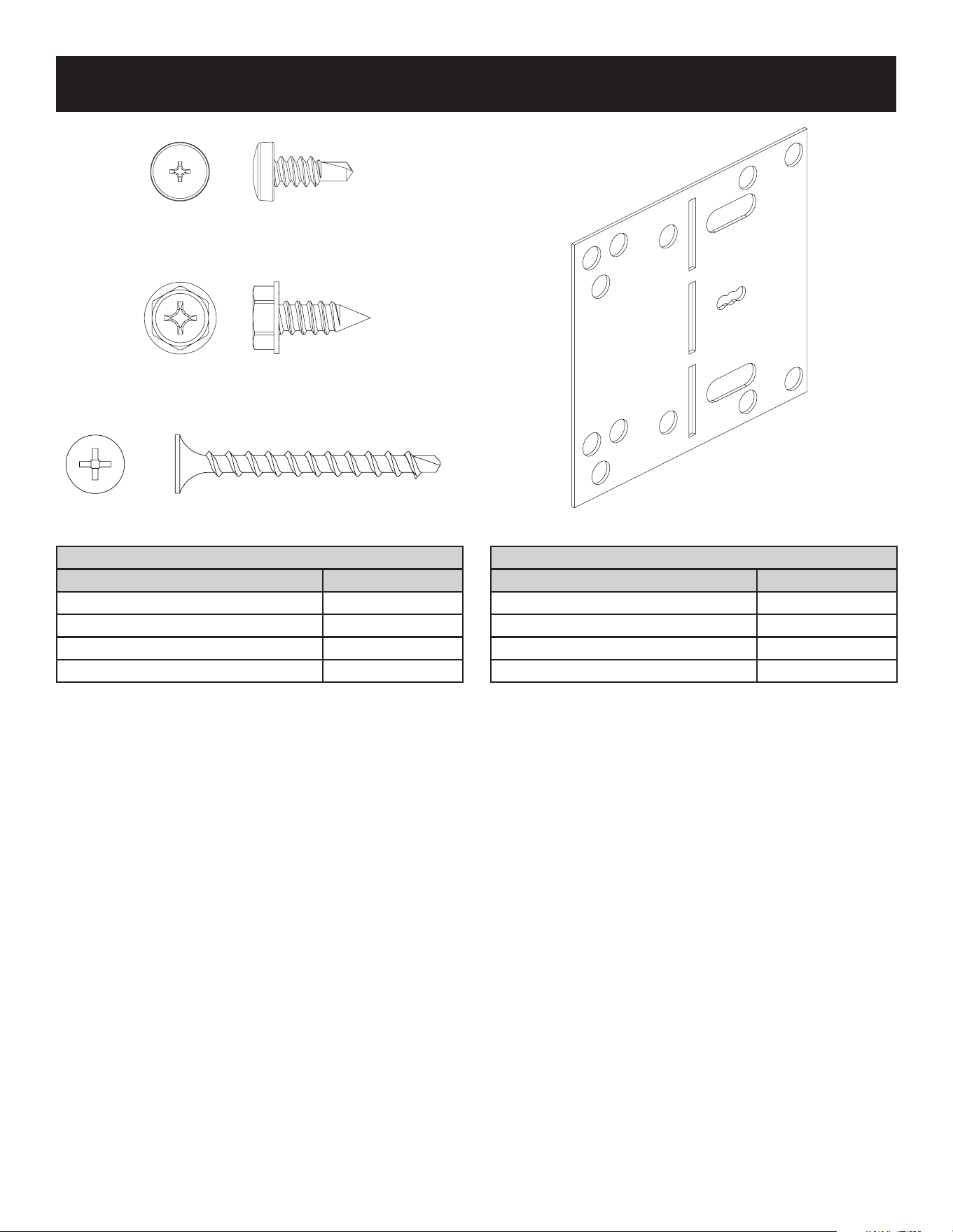
CARTON CONTENTSItems not shown to scale.
VFLB(36,48,60,72)FP90 SERIES
Index
Number
Description
Quantity
Supplied
1 Fireplace 1
2 Non-combustible Board - Top 1
3 Non-combustible Board - Side* 2
4 Barrier Screen Assembly 1
5 Burner Glass 1
6 Side Burner Glass* 2
7 Bushing* 2
8 Stando Bracket* 3
9 Receptacle* 1
10 Remote* 1
11 AA Battery* 4
12 AAA Battery* 3
13 Hardware Pack* 1
14 AC Adaptor* 1
15
Wall mounted Control Box*
1
16 Remote Receiver* 1
17 Button Switch* 2
18 Mounting Bracket* 1
19 Wall Plate* 1
20 Glass Support Center 2
21 Glass Support Side Left* 1
22
Glass Support Side Right*
1
23 Center Reector Assembly 1
24 Extension Receiver Harness 1
25 Junction Box Cover* 1
26 Romex Connector* 1
27 Zip Tie* 1
*Items packaged inside hardware box.
For hardware pack contents, see page 5.
See Parts Lists on pages 57, 59 and 61 for ordering replacement
parts. Do not order batteries, bolts, screws, washers or nuts. They
are standard hardware items and can be purchased at any local
hardware store.
2
3
8
26
10
12
4
13
14
7
11
15
16
17
17
19
18
1
9
23
6
5
25
24
21
20
22
27
2
3
8
26
10
12
4
13
14
7
11
15
16
17
17
19
18
1
9
23
6
5
25
24
21
20
22
27
VFLB(60,72)FP9 carton contents shown above.
CARTON CONTENTS
Page 6 46071-2-0725
#8 X 1” PHILLIPS SELF-DRILLING DRYWALL SCREW
#10 X ½” HEX HEAD SCREW
#10-16 X ½” STAINLESS PHILLIPS HEAD SCREW
NAILING FLANGE
(NOT TO SCALE)
#8 X 1” PHILLIPS SELF-DRILLING DRYWALL SCREW
#10 X ½” HEX HEAD SCREW
#10-16 X ½” STAINLESS PHILLIPS HEAD SCREW
NAILING FLANGE
(NOT TO SCALE)
NAILING FLANGE
(NOT TO SCALE)
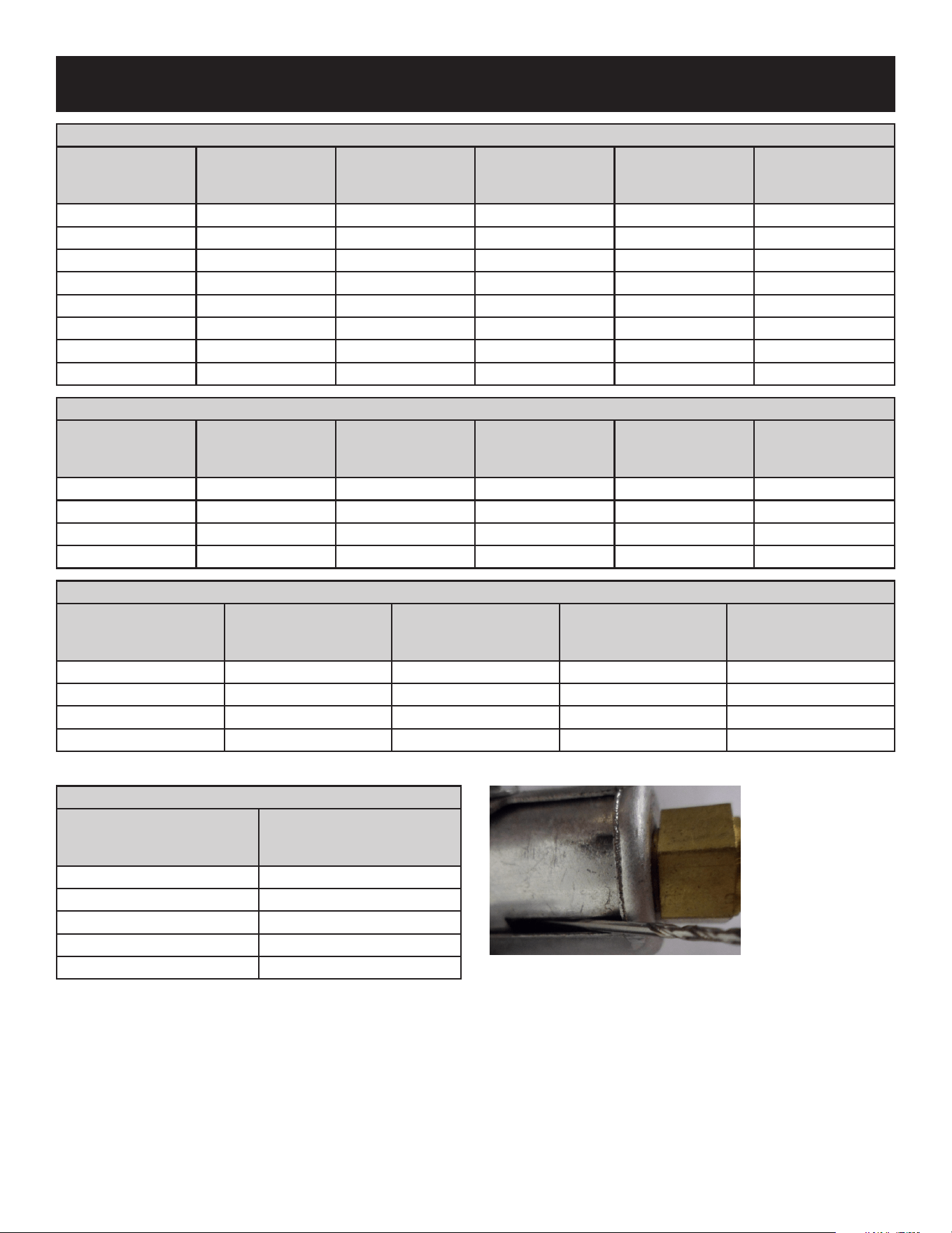
HARDWARE PACK
HARDWARE PACK CONTENTS
VFLB
(
36,48
)
Description Quantity
#10
-
16 x 1/2 Phillips Stainless Screw 8
#10 x 1/2 Phillips Hex Head Screw 16
#8 x 1 Inch Self-Drilling Drywall Screw 20
Nailing Flange 4
VFLB
(
60,72
)
Description Quantity
#4 x 3/8" Phillips Pan Head Screw 4
#10 x 1/2" Phillips Hex Head Screw 14
#8 x 1 Inch Self-Drilling Drywall Screw 9
Nailing Flange 4
See Parts Lists on pages 57, 59 and 61 for replacement parts. Do not order batteries, bolts, screws, washers or nuts. They are standard
hardware items and available at any local hardware store.
46071-2-0725 Page 7
PRODUCT SPECIFICATIONS
VFLB
(
36,48
)
MODELS
Model Gas Type Valve Type Orice
Input BTU
Per Hour
Maximum
Input BTU
Per Hour
Minimum
VFLB36FP30N Natural Millivolt #40 28,000 19,000
VFLB36FP30P Propane Millivolt 1.55mm 28,000 22,000
VFLB36FP90N Natural Intermittent Pilot #40 28,000 19,000
VFLB36FP90P Propane Intermittent Pilot 1.55mm 28,000 22,000
VFLB48FP30N Natural Millivolt #36 32,000 21,000
VFLB48FP30P Propane Millivolt 1.65mm 32,000 23,000
VFLB48FP90N Natural Intermittent Pilot #36 32,000 21,000
VFLB48FP90P Propane Intermittent Pilot 1.65mm 32,000 23,000
VFLB
(
60,72
)
MODELS
Model Gas Type Valve Type Orice
Input BTU
Per Hour
Maximum
Input BTU
Per Hour
Minimum
VFLB60FP90N Natural Intermittent Pilot #32 40,000 27,000
VFLB60FP90P Propane Intermittent Pilot 1.8mm 38,500 30,000
VFLB72FP90N Natural Intermittent Pilot #32 40,000 27,000
VFLB72FP90P Propane Intermittent Pilot 1.8mm 38,500 30,000
GAS SUPPLY PRESSURES
(
Inches Water Column
)
Gas Type Valve Type Maximum Minimum Manifold
Natural Millivolt 10.5 7.0 3.5
Natural Intermittent Pilot 10.5 7.0 3.5
Propane Millivolt 13.0 11.0 10.0
Propane Intermittent Pilot 13.0 11.0 10.0
NOTICE: Air shutter settings are factory set and may not be altered.
AIR SHUTTERS
Model
Air Shutter
Opening
VFLB(36,48)FP(30,90)N
1/8 inch
VFLB(36,48)FP(30,90)P
Fully Open
VFLB(60,72)FP90N 1/16 inch
VFLB60FP90P 5/16 inch
VFLB72FP90P 1/4 inch
(Measure opening
using drill bit.) Set
air shutter opening
using suitable round
object such as a
drill bit. The object
should barely
slide between the
opening.
Figure 1

Page 8 46071-2-0725
HOMEOWNER REFERENCE INFORMATION
We recommend that you record the following information about your replace.
Model Number: ________________________________ Date purchased: ___________________________________
Serial Number: ________________________________ Location of replace: _______________________________
Dealer Name: _________________________________ Dealer Phone: ____________________________________
Notes: _________________________________________________________________________________________
Add Serial Number Sticker Here
46071-2-0725 Page 9
*
*
ACCESSORIES
-
VFLB
(
36,48
)
ACCESSORIES FOR VFLB(36,48)FP30 (MILLIVOLT) MODELS
PART NUMBER DESCRIPTION
FRBTC Battery Operated Remote Control with Thermostat
FRBTP Battery Operated Programmable Remote Control
TRW Remote Wall Thermostat (Wireless)
PART NUMBER
DESCRIPTION
VFLB36FP VFLB48FP
DF361VBL DF481VBL Decorative Front, Beveled, 3/4 inch, Black
DF362VBL DF482VBL Decorative Front, Beveled, 1 1/2 inch, Black
VBP36LKR VBP48LBKR Liner with Burner Cover - Black Reective
VBP36LWR VBP48LBWR Liner with Burner Cover - White Reective
VBP36LSS VBP48LSS Liner – Stainless Steel
HMFA HMFA External Forced Air Management System
HMFA36P HMFA48P Vent-Free Heat Transfer Kit
HMFA36BL HMFA48BL Beveled Frame, Black (For Heat Transfer Kit)
LS60SHF LS60SHF Log Set - 22 Piece
DG1GC DG1GC Decorative Glass Droplets - 1/2 inch Glacier Ice (One kit per one square foot)
DG1SL DG1SL Decorative Glass Droplets - 1/2 inch Sangria Luster (One kit per one square foot)
DG1NXS DG1NXS Decorative Glass Drops - 1 inch Onyx Solid (One kit per one square foot)
DG1CLF DG1CLF Decorative Glass, Crushed - Clear Frost (One kit per one square foot)
DG1BKP DG1BKP Decorative Glass, Crushed - Black Polished (One kit per one square foot)
DG1BUC DG1BUC Decorative Glass, Crushed - Blue Clear (One kit per one square foot)
DG1BCR DG1BCR Decorative Glass, Crushed - Copper Reective (One kit per one square foot)
DG1BZR DG1BZR Decorative Glass, Crushed - Bronze Reective (One kit per one square foot)
DR1FMA DR1FMA Decorative Rock, Ceramic Fiber – Medium (One kit per one square foot)
DRFPA DRFPA Decorative Rock, Ceramic Fiber - Pebble (One kit per ½ square foot)
LK5 LK5 120V Lighting Kit – Requires Switch or Rheostat
NOTICE: The total burner cover area for decorative glass or rocks equals 1.75 square feet for VFLB36FP and 2.25 square feet for VFLB48FP.
Decorative Glass Droplets can be mixed with crushed glass. One box of crushed glass covers 1 sq. ft. Glass colors can be mixed.
NOTICE: Never place decorative media material on or next to the burner. Decorative glass or rocks should not be higher than the lip of the
burner cover.
NOTICE: If installing a decorative front, an oset between the nishing materials and replace opening is required. Refer to pages 29 and
31 as well as the installation instructions provided with the decorative front for more information.
*
Must be purchased together.
Page 10 46071-2-0725
ACCESSORIES
-
VFLB
(
60,72
)
REQUIRED ACCESSORIES
Accessories For - VFLB(60,72)FP90(N,P)-1
PART NUMBER
DESCRIPTION
VFLB60 VFLB72
DG1CLF DG1CLF Decorative Glass, Crushed - Clear Frost (One kit per one square foot) Recommended
DG1BKP DG1BKP Decorative Glass, Crushed - Black Polished (One kit per one square foot)
DG1BUC DG1BUC Decorative Glass, Crushed - Blue Clear (One kit per one square foot)
DG1BCR DG1BCR Decorative Glass, Crushed - Copper Reective (One kit per one square foot)
DG1BZR DG1BZR Decorative Glass, Crushed - Bronze Reective (One kit per one square foot)
NOTICE: Decorative crushed glass is required for installation. Clear Frost is recommended. Decorative = Glass Droplets can be
mixed with crushed glass, but cannot be substituted for crushed glass. One box of crushed glass covers 1 sq. ft. Glass colors can be
mixed, and transparent and translucent crushed glass makes LED lights more visible.
NOTICE: Requires ve square feet for VFLB60, six square feet for VFLB72.
NOTICE: Never place decorative media material on or next to the burner.
OPTIONAL ACCESSORIES
Accessories For - VFLB(60,72)FP90(N,P)-1
PART NUMBER
DESCRIPTION
VFLB60 VFLB72
DF601VBL DF721VBL Decorative Front, Beveled, 3/4 inch, Black
DF602VBL DF722VBL Decorative Front, Beveled, 1 1/2 inch, Black
VBP60LKR VBP72LKR Liner - Black Reective Glass
VBP60LSS VBP72LSS Liner – Stainless Steel
HMFA HMFA External Forced Air Management System
HMFA60P HMFA72P Vent-Free Heat Transfer Kit
HMFA60BL HMFA72BL Beveled Frame, Black (For Heat Transfer Kit)
LS60DF LS72DF Log Set
DG1GC DG1GC Decorative Glass Droplets - 1/2 inch Glacier Ice (Used as accent only)
DG1SL DG1SL Decorative Glass Droplets - 1/2 inch Sangria Luster (Used as accent only)
DG1NXS DG1NXS Decorative Glass Drops - 1 inch Onyx Solid (Used as accent only)
DRFPA DRFPA Decorative Rock, Ceramic Fiber - Pebble (Used as accent only)
NOTICE: If installing a decorative front, an oset between the nishing materials and replace opening is required. Refer to pages 29 and
31 as well as the installation instructions provided with the decorative front for more information.
*
Must be purchased together.
46071-2-0725 Page 11
INTRODUCTION
The term qualied agency means any individual, rm, corporation
or company which either in person or through a representative is
engaged in and is responsible for (a) the installation or replacement
of gas piping or (b) the connection, installation, repair or servicing
of equipment, who is experienced in such work, familiar with all
precautions required and has complied with all the requirements
of the authority having jurisdiction.
Commonwealth of Massachusetts: The installation must be
made by a licensed plumber or gas tter in the Commonwealth
of Massachusetts.
Sellers of unvented propane or natural gas-red supplemental
replaces shall provide to each purchaser a copy of 527 CMR
30 upon sale of the unit.
In the Commonwealth of Massachusetts, unvented propane and
natural gas-red space heaters shall be prohibited in bedrooms
and bathrooms.
The installation must conform with local codes or, in the absence
of local codes, with the National Fuel Gas Code, ANSI Z223.1.*/
NFPA 54.
*Available from the American National Standards Institute, Inc.
1430 Broadway, New York, N.Y. 10018.
WARNING
Failure to keep the primary air opening(s) of the burner(s)
clean may result in sooting and property damage.
FOR THE INSTALLER
• Installation and repair should be done by a qualied service
person. The replace should be inspected before use and at
least annually by a qualied service person. More frequent
cleaning might be required due to excessive lint from carpeting,
bedding material, etc. It is imperative that control compartments,
burners and circulating air passageways of the replace be
kept clean. Keep burner and control compartment clean.
• An unvented room replace having an input rating of more than
6,000 Btu per hour shall not be installed in a bathroom
• An unvented room fireplace having an input rating of more
than 10,000 Btu per hour shall not be installed in a bedroom
or bathroom.
• Use Non-Combustible Materials where indicated for the
replace installation. Non-combustible material do not ignite
or burn as a result of using the replace. These include metal,
brick, ceramic, concrete, slate, glass, and plaster. Adhesives
must be rated for high temperatures. Any mechanical fasteners
used to install material must also be non-combustible,
including wall anchors and tile spacers. Materials that pass
the ASTM E 136 test (Standard Test Method for Behavior of
Materials in a Vertical Tube Furnace at 750C) are considered
non-combustible.
• Install the replace out of household trac and away from
furniture and draperies. The high temperatures produced by
the replace create an ignition risk.
INSTRUCTIONS TO INSTALLER
1. Leave instruction manual with owner after installation.
2. Have owner register online or ll out and mail the Product
Registration Card supplied with the unvented replace.
3. Fill out Homeowner Reference Information on page 7 .
4. Show homeowner how to start and operate the replace.
5. Show homeowner basic maintenance.
Consult the local Building Department regarding regulations, codes
or ordinances which apply to the installation of an unvented replace.
This replace may be installed in an aftermarket* manufactured
(mobile) home, where not prohibited by state or local codes.
*Aftermarket: Completion of sale, not for purpose of resale, from
the manufacturer.
WELL HEAD GAS INSTALLATIONS
Some natural gas utilities use “well head” gas. This may aect the Btu
output of the unit and promote sooting. Units shall not be converted
to use well head gas.
This appliance is only for use with the type of gas indicated on the
rating plate. This appliance is not convertible for use with other gases.
WARNING
Any change to this replace or its controls can be dangerous.
Improper installation or use of the replace can cause
serious injury or death from re, burns, explosion or carbon
monoxide poisoning.
This replace is intended for supplemental heating.
Any alteration of the original design, installed other than as shown
in these instructions or use with a type of gas not shown on the
rating plate is the responsibility of the person and company making
the change.
IMPORTANT
All correspondence should refer to complete Model Number, Serial
Number and type of gas. (See page 7.)
WARNING
This appliance is equipped for natural or propane gas. Field
conversion is not permitted.
During manufacture, this replace is treated with oils, lms and
bonding agents. These are not harmful but may produce smoke
and odor as they burn o during initial operation. This is normal.
Open window to vent any smoke or odor.
INSTALLATION ON RUGS AND TILE
If this replace is installed directly on carpeting, tile or other
combustible material other than wood ooring the replace shall
be installed on a metal or wood panel extending the full width and
depth of the replace.
QUALIFIED INSTALLING AGENCY
Installation and replacement of gas piping, gas utilization equipment
or accessories and repair and servicing of equipment shall be
performed only by a qualied agency.
Page 12 46071-2-0725
IMPORTANT INFORMATION
WARNING
Read and follow these safety precautions prior to operating
this appliance. Failure to follow these precautions may
result in death, injury, or property damage.
All correspondence should refer to complete Model Number, Serial
Number and type of gas. Fill out the Homeowner Reference Section
on page 7 in installation manual.
FOR THE HOMEOWNER
• Do not allow Combustible Materials adjacent to or in contact
with the replace. Combustible materials include wood,
compressed paper, plant bers, or other materials that will
burn. These materials are considered combustible even
when treated with re-retardant chemicals
.
• Alert children and adults to the hazards of high surface
temperatures. Warn them to stay away to avoid burns and
clothing ignition.
• Supervise children when they are in the same room as the
replace.
• Do not place clothing or other ammable material on or near the
replace.
• Any safety screen or guard removed for servicing the replace
must be replaced prior to operating the replace.
• Keep replace area clear and free from combustible materials,
gasoline and other ammable vapors and liquids.
• Do not use this replace if any part has been under water.
Immediately call a qualied service technician to inspect the
replace and to replace any part of the control system and
any gas control which has been under water.
•
Operate replace with all glass panels and barrier screen in
place.
• Do not place embers (rock wool) in this replace.
• Do not place lava rocks in this replace.
WARNING
This replace is not for use with solid fuels. Improper use
of the replace can cause serious injury or death from re,
burns, explosions or carbon monoxide poisoning.
MILLIVOLT 3 SERIES ONLY 750 MILLIVOLT SYSTEM
When igniting the pilot, the thermocouple produces millivolts
(electrical current) which energizes the magnet in the gas valve.
After 30 seconds to 1 minute time period, release the gas control
knob and the pilot will stay ON. Allow pilot ame to operate an
additional one to two minutes before turning the gas control knob
from the PILOT position to the ON position. This time period
allows the millivolts (electrical energy) to build-up to a sucient
level allowing the gas control to operate properly.
MAINTENANCE AND SERVICE
Although the frequency of servicing and maintenance will depend
on use and the type of installation, a qualied service technician
should perform an appliance checkup at the beginning of each
heating season. Specic guidelines regarding each appliance
maintenance task are listed below.
NOTICE: It is normal for steel appliances to make expansion and/
or contraction noise during the start-up or cool-down cycle. Similar
noises are found with a furnace heat exchanger or car engine.
NOTICE: During manufacture, components of this replace insert
are treated with oils, lms or bonding agents. These are not harmful,
but may produce smoke and smells as they are burned o during
the initial operation of the replace insert. This is normal. Open a
window to ventilate the area.
Only glass approved for use by the manufacturer in replace may
be used for replacement. The glass replacement must be done by
a licensed or qualied service person.
WARNING
• Avoid breaking the glass.
• Do not operate this appliance without the glass panel
and barrier screen, or with a broken glass panel.
• Replace only with Empire Comfort Systems parts.
CAUTION
Do not use Ammonia-based or abrasive cleaners on glass.
To prevent ectching or discoloring, clean the glass with
Fireplace Glass Cleaner (available from the dealer).
Do not attempt to clean glass when glass is hot.
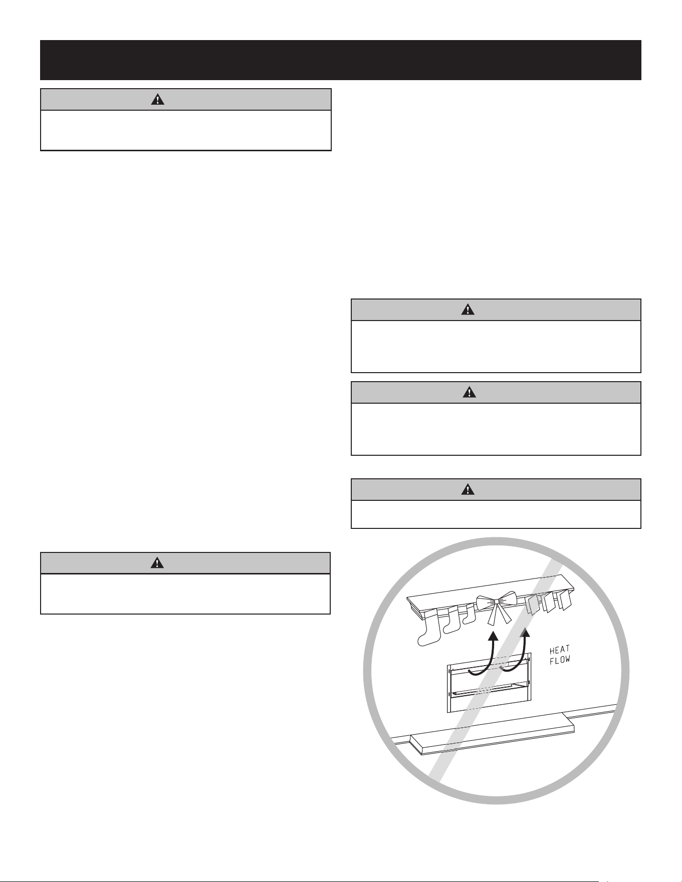
COMBUSTIBLE MATERIAL
WARNING
Do not attach combustible material to the mantel of your
replace. This is a re hazard.
Figure 2
46071-2-0725 Page 13
WARNING
When used without adequate combustion and ventilation air,
appliance may give o CARBON MONOXIDE, an odorless,
poisonous gas.
Do not install appliance until all necessary provisions are
made for combustion and ventilation air. Consult the written
instructions provided with the appliance for information
concerning combustion and ventilation air. In the absence
of instructions, refer to the National Fuel Gas Code, ANSI
Z223.1/NFPA 54, Air for Combustion and Ventilation, or
applicable local codes.
This appliance is equipped with a PILOT LIGHT SAFETY
SYSTEM designed to turn o the appliance if not enough
fresh air is available.
The pilot light safety system senses the depletion of oxygen at
its location. If this replace is installed in a structure having a
high vertical dimension, the possibility exists that the oxygen
supply at the higher levels will be less than that at the replace.
In this type of application, a fan to circulate the structure air will
minimize this eect. The use of this fan will also improve the
comfort level in the structure. When a fan is used to circulate
air, it should be located so that the air ow is not directed at
the burner.
DO NOT TAMPER WITH PILOT LIGHT SAFETY SYSTEM!
If fireplace shuts off, do not relight until you provide fresh air.
If replace keeps shutting o, have it serviced. Keep burner
and control compartment clean. See installation and operating
instructions.
WARNING
CARBON MONOXIDE POISONING MAY
LEAD TO DEATH.
Early signs of carbon monoxide poisoning resemble the u,
with headache, dizziness and/or nausea. If you have these
signs, replace may not be working properly. Get fresh air at
once! Have replace serviced.
Some people — pregnant women, persons with heart or lung
disease, anemia, those under the influence of alcohol , those
at high altitudes — are more affected by carbon monoxide
than others.
DANGER
The installer is responsible for the verifying the correct
position of the air shutter and adjusting it if required. If not
adjusted to the proper opening, a re, explosion, or production
of carbon monoxide may result causing property damage,
personal injury or loss of life.
DANGER
The installer is responsible for testing all connections for
gas leaks. A gas leak will create a situation where a re,
explosion, or production of carbon monoxide may result
causing property damage, personal injury or loss of life.
WARNING
Do not use a blower insert, heat exchanger insert or other
accessory not approved for use with this heater. The use of
accessories not tested and approved for use with this replace
will create a situation where a re, explosion, or production
of carbon monoxide may result causing property damage,
personal injury or loss of life.
WARNING
This replace needs fresh air for ventilation to run properly.
Inadequate air supply may create a situation where a re,
explosion, or production of carbon monoxide may result
causing property damage, personal injury or loss of life. This
replace has an ODS (oxygen depletion sensor) which will
shut down the replace if adequate fresh air is not available.
See troubleshooting section in the instructions.
WARNING
Do not operate this replace unless all components including
burners and controls are in good working condition. Never
operate this replace if any optional log or twig is broken.
Replacement components are available through your local
dealer as indicated in the How to Order Repair Parts section
of the replace manual. See Page 47.
WARNING
"FIRE, EXPLOSION, AND ASPHYXIATION HAZARD
Improper adjustment, alteration, service, maintenance or
installation of this heater or its controls can cause death or
serious injury.
Read and follow instructions and precautions in User's
Information Manual provided with this heater."
IMPORTANT SAFETY INFORMATION

Page 14 46071-2-0725
SAFETY INFORMATION FOR USERS OF PROPANE GAS
Propane is a ammable gas which can cause res and
explosions. In its natural state, propane is odorless and
colorless. You may not know all the following safety
precautions which can protect both you and your family
from an accident. Read them carefully now, then review
them point by point with the members of your household.
Someday when there may not be a minute to lose, everyone's
safety will depend on knowing exactly what to do. If, after
reading the following information, you feel you still need more
information, please contact your gas supplier.
PROPANE GAS WARNING ODOR
If a gas leak happens, you should be able to smell the gas because of the odorant
put in the Propane Gas. That's your signal to go into immediate action!
•
Do not operate electric switches, light matches, use your phone.
Do not do anything that could ignite the gas.
• Get everyone out of the building, vehicle, trailer, or area. Do
that IMMEDIATELY.
• Close all gas tank or cylinder supply valves.
• Propane Gas is heavier than air and may settle in low areas
such as basements. When you have reason to suspect a gas
leak, keep out of basements and other low areas. Stay out
until reghters declare them to be safe.
• Use your neighbor's phone and call a trained Propane Gas
service person and the re department. Even though you may
not continue to smell gas, do not turn on the gas again. Do
not re-enter the building, vehicle, trailer, or area.
• Finally, let the service man and reghters check for escaped
gas. Have them air out the area before you return. Properly
trained Propane Gas service people should repair the leak,
then check and relight the gas appliance for you.
NO ODOR DETECTED - ODOR FADE
Some people cannot smell well. Some people cannot smell
the odor of the chemical put into the gas. You must nd out if
you can smell the odorant in propane. Smoking can decrease
your ability to smell. Being around an odor for a time can aect
your sensitivity or ability to detect that odor. Sometimes other
odors in the area mask the gas odor. People may not smell the
gas odor or their minds are on something else. Thinking about
smelling a gas odor can make it easier to smell.
The odorant in Propane Gas is colorless, and it can fade under
some circumstances. For example, if there is an underground
leak, the movement of the gas through soil can lter the odorant.
Odorants in Propane Gas also are subject to oxidation.
This fading can occur if there is rust inside the storage tank or in
iron gas pipes. The odorant in escaped gas can adsorb or absorb
onto or into walls, masonry and other materials and fabrics in a
room. That will take some of the odorant out of the gas, reducing
its odor intensity.
Propane Gas may stratify in a closed area, and the odor intensity
could vary at dierent levels. Since it is heavier than air, there
may be more odor at lower levels. Always be sensitive to the
slightest gas odor. If you detect any odor, treat it as a serious
leak. Immediately go into action as instructed earlier.
SOME POINTS TO REMEMBER
•
Learn to recognize the odor of Propane Gas. Your local
Propane Gas Dealer can give you a "Scratch and Sni" pam-
phlet. Use it to nd out what the propane odor smells like. If you
suspect that your Propane Gas has a weak or abnormal odor,
call your Propane Gas Dealer.
•
If you are not qualied, do not light pilot lights, perform service,
or make adjustments to appliances on the Propane Gas system.
If you are qualied, consciously think about the odor of Propane
Gas prior to and while lighting pilot lights or performing service
or making adjustments.
• Sometimes a basement or a closed-up house has a musty
smell that can cover up the Propane Gas odor. Do not try to
light pilot lights, perform service, or make adjustments in an
area where the conditions are such that you may not detect
the odor if there has been a leak of Propane Gas.
• Odor fade, due to oxidation by rust or adsorption on walls of
new cylinders and tanks, is possible. Therefore, people should
be particularly alert and careful when new tanks or cylinders
are placed in service. Odor fade can occur in new tanks, or
reinstalled old tanks, if they are lled and allowed to set too
long before relling.
Cylinders and tanks which have been out of service for a time
may develop internal rust which will cause odor fade. If such
conditions are suspected to exist, a periodic sni test of the
gas is advisable. If you have any question about the gas
odor, call your Propane Gas Dealer. A periodic sni test
of the Propane Gas is a good safety measure under any
condition.
• If, at any time, you do not smell the Propane Gas odorant and
you think you should, assume you have a leak. Then take the
same immediate action recommended above for the occasion
when you do detect the odorized Propane Gas.
• If you experience a complete "gas out," (the container is under
no vapor pressure), turn the tank valve o immediately. If the
container valve is left on, the container may draw in some air
through openings such as pilot light orices. If this occurs,
some new internal rusting could occur. If the valve is left
open, then treat the container as a new tank. Always be sure
your container is under vapor pressure by turning it o at the
container before it goes completely empty or having it relled
before it is completely empty.

46071-2-0725 Page 15
Water vapor is a by-product of gas combustion. An unvented room
heater produces approximately one ounce (30ml) of water for every
1,000 BTU (.3KW's) of gas input per hour.
Unvented room heaters are recommended as supplemental heat
(a room) rather than a primary heat source (an entire house). In
most supplemental heat applications, the water vapor does not
create a problem, but helps correct the low humidity atmosphere
experienced during cold weather.
The following steps will help ensure that water vapor does not
become a problem.
1. Be sure the heater is sized properly for the application, including
ample combustion air and circulation air.
2. If high humidity is experienced, a dehumidier will help lower
the water vapor content of the air.
3. Do not use an unvented room heater as the primary heat source.
WATER VAPOR: A BY-PRODUCT OF UNVENTED ROOM HEATERS
PROPER PRIMARY AIRFLOW INTO BURNER
For proper burner operation and ame appearance, the ow of
primary air into the venturi tube, located at the gas inlet of the
burner, must not be reduced. This ow of air is reduced if dirt, lint
or other obstructions build-up around or inside the venturi. Any
obstruction in the venturi tube area must be removed. The ow of
air into the venturi is also reduced if the gas orice isn’t centered
in the venturi inlet and/or is not aligned with the venturi. Any
misalignment of the burner orice may be corrected by bending
the shutter cap holding the orice to the inlet of the venturi tube.
CEILING FANS, PORTABLE FANS OR LOGS INSTALLED
NEAR COLD AIR RETURNS
Ceiling fans or oscillating oor type fans need to be monitored
during the operation of a vent-free replace. If the air blows directly
into the ame causing it to disrupt the ame, it should be turned o
or redirected. Ceiling fans could be reversed to possibly eliminate
ame impingement, and the oor fan should be redirected. Upon
installation, be aware of any cold air returns or vents in the proximity
of the replace. Any draft created around a vent-free replace can
cause the ame to impinge on the logs or decorative media and
create a sooting situation.
IMPORTANT INSTALLATION GUIDELINES
TELEVISION CONSIDERATIONS
Installing a television above a replace has become increasingly
popular; however, the area above any replace gets hot and most
TV manufacturers recommend against placing their products near
a heat source.
If a television is installed above this replace, Empire Comfort
Systems accepts no responsibility for damage or injuries. Follow
the television manufacturer’s installation instructions, including any
recommendations regarding proximity to heat sources.
If a TV is installed above the replace, turn o the replace and let it
cool completely before servicing or touching any buttons on the TV.
NOTICE FOR FINISHING MATERIALS
Due to the variable properties of natural stone, the material may
have stress points that are unpredictable when installed above or
around the replace. These stress points may result in cracking of
the nish materials. Empire Comfort Systems is not responsible
for the nishing materials used with our replaces.
Page 16 46071-2-0725
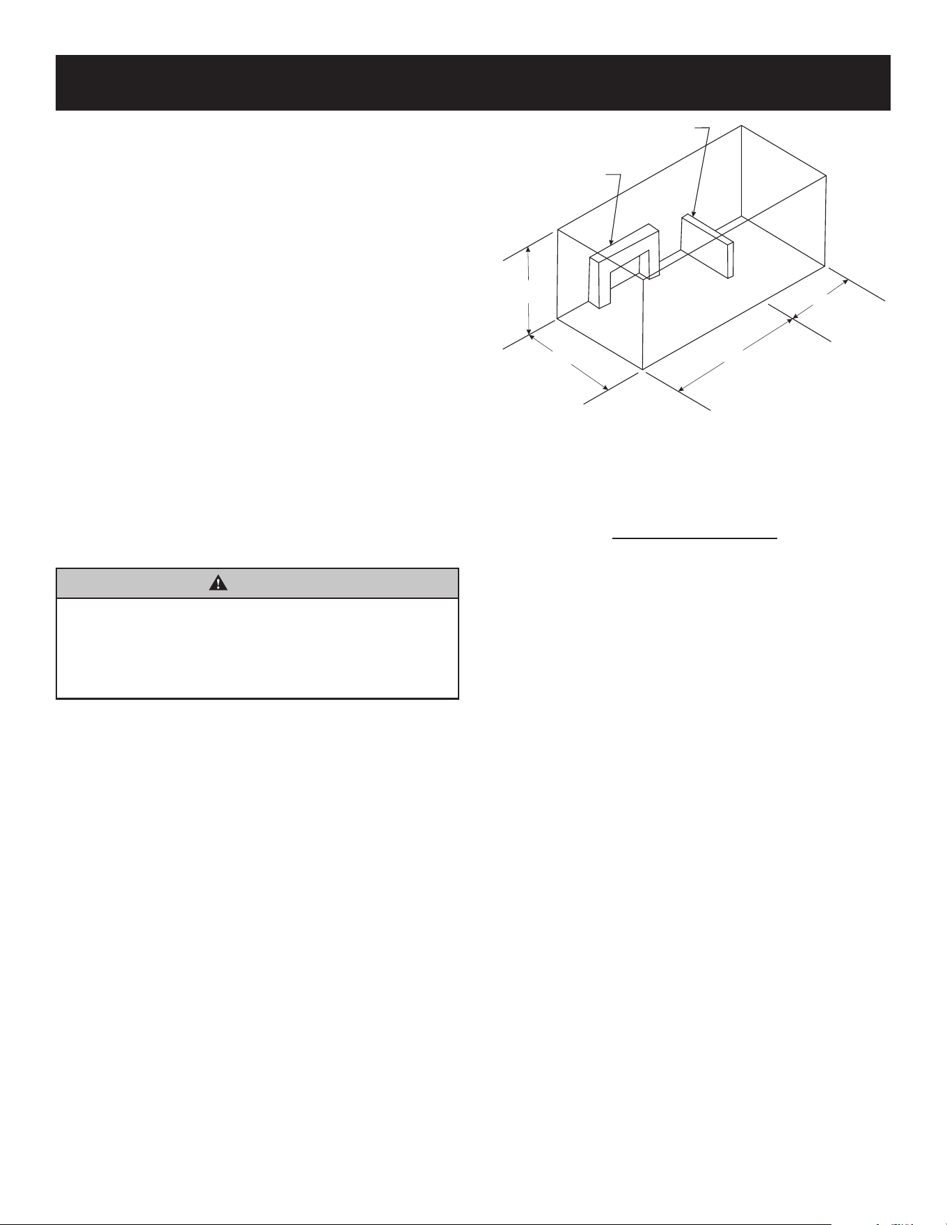
This heater shall not be installed in a conned space unless provisions
are provided for adequate combustion and ventilation air.
The National Fuel Gas Code denes a conned space as a space whose
volume is less than 50 cubic feet per 1,000 Btu per hour (4.8m
3
per kw)
of the aggregate input rating of all appliances installed in that space and
an unconned space as a space whose volume is not less than 50 cubic
feet per 1,000 Btu per hour (4.8 m
3
per kw) of the aggregate input rating
of all appliances installed in that space. Rooms communicating directly
with the space in which the appliances are installed, through openings
not furnished with doors, are considered a part of the unconned space.
UNUSUALLY TIGHT CONSTRUCTION
The air that leaks around doors and windows may provide enough fresh
air for combustion and ventilation. However, in buildings of unusually
tight construction, additional fresh air must be provided.
Unusually tight construction is dened as construction where:
a. Walls and ceilings exposed to the outside atmosphere have a
continuous water vapor retarder with a rating of one perm or
less with any openings gasketed or sealed, and
b. Weatherstripping has been added on openable windows and
doors, and
c. Caulking or sealants are applied to areas such as joints around
window and door frames, between sole plates and oors, between
wall-ceiling joints, between wall panels, at penetrations for
plumbing, electrical, and gas lines, and at other openings.
If the home meets all three criteria above, additional fresh air must be
provided.
WARNING
If the area in which the heater may be operated is smaller than
that dened as an unconned space or if the building is of
unusually tight construction, provide adequate combustion and
ventilation air by one of the methods described in the National
Fuel Gas Code, ANSI Z223.1/NFPA 54, Air for Combustion and
Ventilation, or applicable local codes.
PROVISIONS FOR ADEQUATE COMBUSTION & VENTILATION AIR
H
W
L
1
L
2
FIREPLACE
DIVIDER
Example of Large Room with 1/2 Wall divider.
Figure 3
The following formula can be used to determine the maximum heater
rating per the denition of unconned space:
Btu/Hr =
(L
1
+ L
2
)FT x (W)FT x (H)FT
x 1000
50
If the area in which the heater may be operated is smaller than that dened
as an unconned space, provide adequate combustion and ventilation
air by one of the methods described in the National Fuel Gas Code
,
ANSI Z223.1, NFPA54.
Adhere to all codes, or in their absence, the latest edition of THE
NATIONAL FUEL GAS CODE ANSI Z223.1/NFPA54 which can be
obtained from:
American National Standards Institute National Fire Protection
Association, Inc.
11 West 42nd St. Batterymarch Park
New York, NY 10018 Quincy, MA 02269
46071-2-0725 Page 17
PROVISIONS FOR ADEQUATE COMBUSTION & VENTILATION AIR
If the area in which the heater will be operated is smaller than that
dened as an unconned space, provide adequate combustion and
ventilation air by one of the following methods:
1. Add the space of an adjoining room, and rework the equation. If
doing so creates an unconned space, remove door to adjoining
room or add ventilation grills between rooms. See Ventilation
Air From Inside Building.
2. Vent room directly to the outdoors. See Ventilation Air From
Outdoors.
3. Install a lower Btu per hour heater, if lower Btu per hour size
makes room unconned.
If the actual Btu per hour used is less than the maximum Btu per
hour the space can support, the space is an unconned space. No
additional fresh air ventilation is needed.
WARNING
Additional ventilation air must be provided in a conned space.
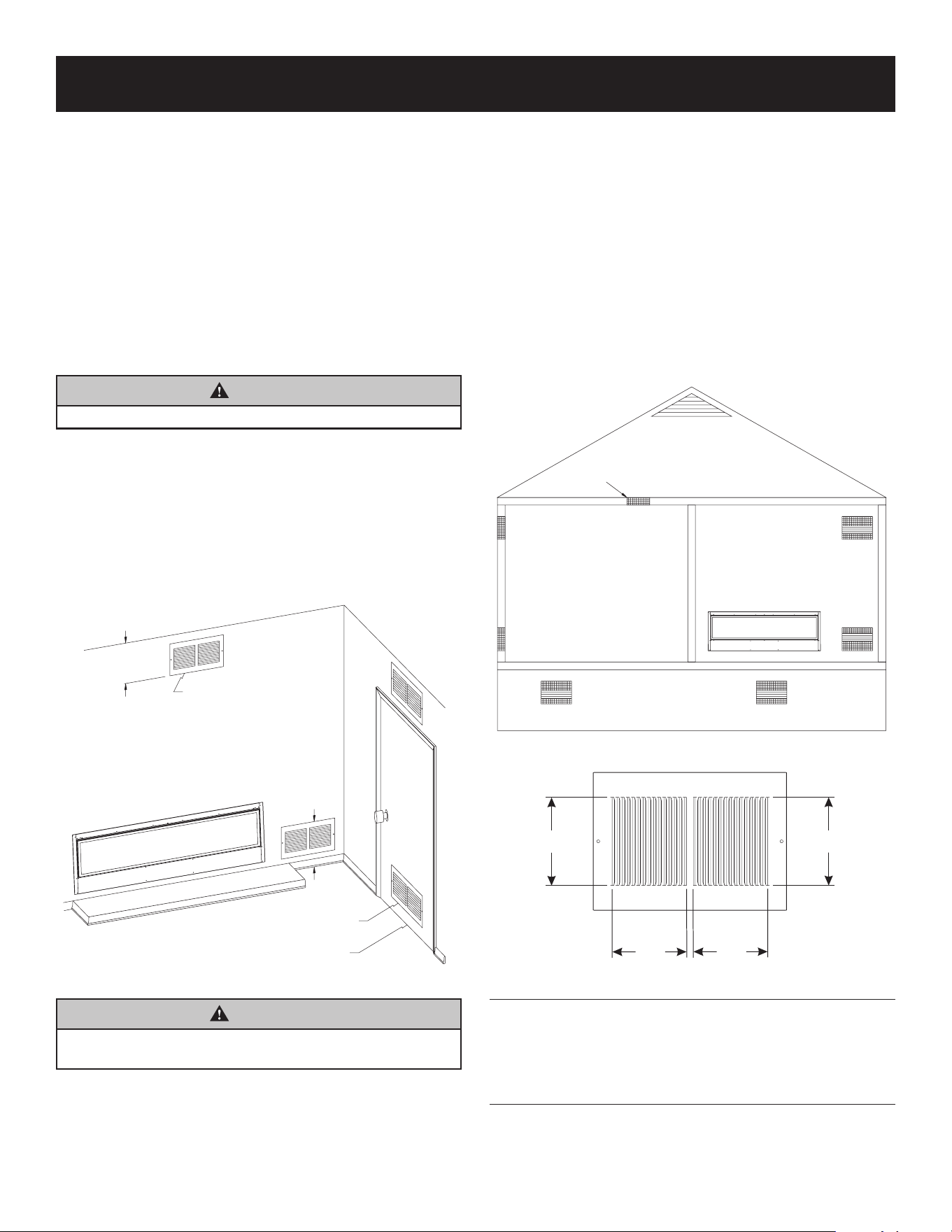
Ventilation Air From Inside Building
This fresh air would come from an adjoining unconned space.
When ventilating to an adjoining unconned space, two permanent
openings must be provided; one within 12" of the ceiling and one
within 12" of the oor on the wall connecting the two spaces. See
Options 1 and 2, Figure 4. Door(s) into adjoining room may also be
removed. See option 3, Figure 4. Each ventilation grill or opening
shall have a minimum free area of one square inch per 1,000 BTUH
of the total input rating of the gas equipment in the conned space,
but totaling no less than 100in
2
.
12”
(305mm)
OPTION 1.
VENTILATION GRILLS
INTO ADJOINING ROOM
12”
(305mm)
OPTION 2. VENTILATION GRILLS
INTO ADJOINING ROOM
OPTION 3. REMOVE DOOR INTO ADJOINING ROOM
Figure 4
WARNING
When adding adjoining spaces, the combined spaces must
have enough fresh air to supply all appliances in both spaces.
Ventilation Air From Outdoors
Provide extra fresh air by using ventilation grills or ducts. Two
permanent openings must be provided; one within 12" of the ceiling
and one with 12" of the oor. Connect these items directly to the
outdoors or spaces open to the outdoors. These spaces include
attics and crawl spaces. For direct communication with the outdoors
through a vertical duct, each grill shall have a free area opening
of one square inch per 4,000 BTU/Hr of heater input rating. If a
horizontal duct is used, each grill opening shall have a free area of
one square inch per 2,000 BTU/Hr. Follow the National Fuel Code
ANSI Z223.1/NFPA54, Air for Combustion and Ventilation for required
size of ventilation grills or ducts.
IMPORTANT: Do not provide openings for inlet or outlet air into attic
if attic has a thermostat-controlled power vent. Heated air entering
the attic will activate the power vent.
OUTLET
AIR
OUTLET
AIR
VENTILATED
ATTIC
INLET
AIR
TO
ATTIC
TO
CRAWL
SPACE
INLET
AIR
VENTILATED
CRAWL SPACE
Figure 5
A1 A2
B1
B2
A1 x B1 = C1
A2 x B2 = C2
C1 + C2 = Sq. In. Required
Example: For a 30,000 BTU Heater, 1 sq. in. per 1,000 BTU equals
30 sq. in. of opening.
(A1) 5in
2
x (B1) 3in
2
= (C1) 15in
2
(A2) 5in
2
x (B2) 3in
2
= (C2) 15in
2
(C1) 15in
2
+ (C2) 15in
2
= 30in
2
NOTE: When measuring B1 and B2, the cumulative total of louver
thicknesses shall be subtracted.
Figure 6
Page 18 46071-2-0725
FIREPLACE DIMENSIONS
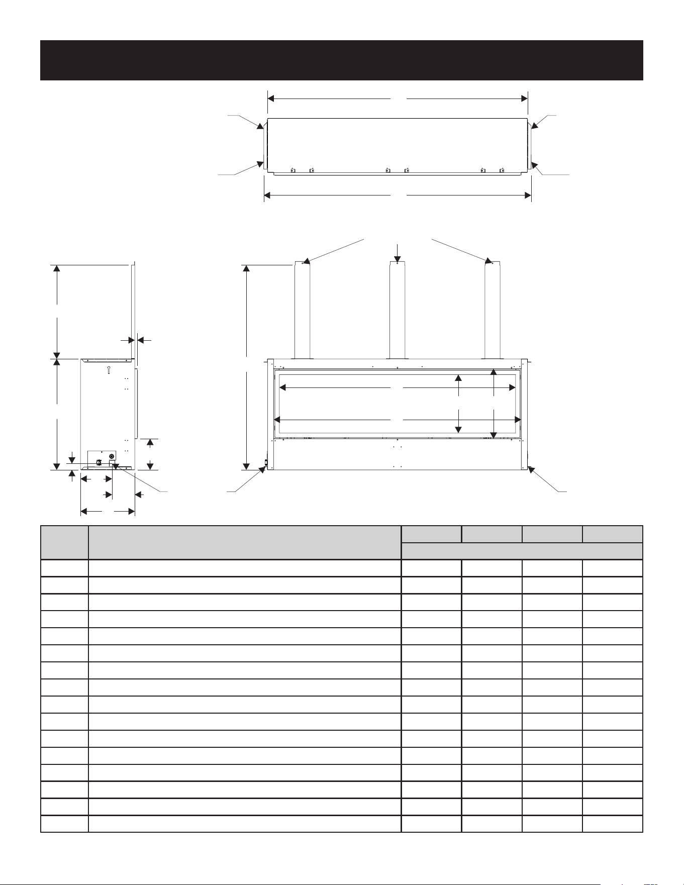
INDEX
LETTER
DIMENSION DESCRIPTION
VFLB36FP VFLB48FP VFLB60FP VFLB72FP
DIMENSIONS
(
In Inches
)
A The Maximum Height Of Firebox Face (Excluding Standos) 22
-
1/2 22
-
1/2 22
-
1/2 22
-
1/2
B
The Maximum Width Of The Firebox Face (Excluding Nailing Flanges)
42
-
3/16 54
-
3/16 66
-
3/16 78
-
3/16
C The Maximum Depth Of The Firebox 11 11 11
-
1/16 11
-
1/16
D The Height Of The Firebox Opening 14
-
1/8 14
-
1/8 14
-
1/8 14
-
1/8
E The Width Of The Firebox Opening 38
-
1/16 50
-
1/16 62
-
1/16 74
-
1/16
F The Interior Depth Of The Firebox (Not Shown) 9
-
9/16 9
-
9/16 9
-
7/8 9
-
7/8
G The Rear Exterior Width Of The Firebox 40
-
3/4 52
-
3/4 64
-
3/4 76
-
3/4
H The Height To The Firebox Standos 19 19 19 19
K Height From The Bottom Of The Firebox To The Gas Line Opening 1
-
1/4 1
-
1/4 1
-
1/4 1
-
1/4
L Depth From The Front Of The Firebox To Gas Line Opening 4
-
9/16 4
-
9/16 4
-
9/16 4
-
9/16
M Depth From Rear Of Firebox To Gas Line Opening 6
-
7/16 6
-
7/16 6
-
7/16 6
-
7/16
N Screen Barrier Opening Height 11
-
7/8 11
-
7/8 11
-
7/8 11
-
7/8
O Screen Barrier Opening Width 35
-
7/8 47
-
7/8 59
-
7/8 71
-
7/8
Q Distance From Fireplace Bottom To Fireplace Opening 6
-
3/8 6
-
3/8 6
-
3/8 6
-
3/8
S Overall Height To Header 41
-
1/2 41
-
1/2 41
-
1/2 41
-
1/2
T Opening Lip 1/2 1/2 1/2 1/2
B
G
S
DN
O
E
HOLES IN
STANDOFF
C
L
M
Q
H
A
K
T
GAS LINE
ACCESS
ELECTRICAL
ACCESS
GAS LINE
ACCESS
GAS LINE
ACCESS
ELECTRICAL
ACCESS
GAS LINE
ACCESS
46071-2-0725 Page 19
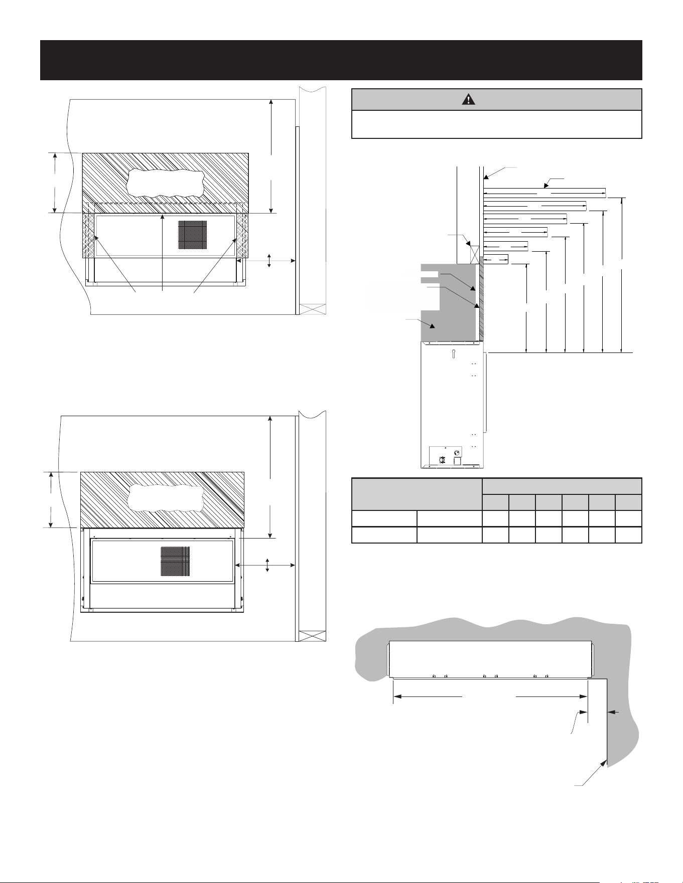
CLEARANCES
MINIMUM CLEARANCE
TO PERPENDICULAR
COMBUSTIBLE
SIDE-WALL
36”
MINIMUM CLEARANCE
TO CEILING
AND ENCLOSURE TOP
NON COMBUSTIBLE BOARD
REQUIRED IN THESE AREAS
(SUPPLIED WITH FIREPLACE)
NON-COMBUSTIBLE BOARD
REQUIRED IN THIS AREA
(SUPPLIED WITH FIREPLACE)
22 1/2”
VFLB36FP: 6”
VFLB48FP: 18”
NOTICE: Combustible material is allowed below a replace viewing
area opening and outside the non-combustible board.
NOTICE: If installing a decorative front, an oset between the
nishing materials and replace opening is required. Refer to page
27 for more information.
Figure 7 - Finishing Option 1
MINIMUM CLEARANCE
TO PERPENDICULAR
COMBUSTIBLE SIDE-WALL
36”
MINIMUM CLEARANCE
TO CEILING
AND ENCLOSURE TOP
NON-COMBUSTIBLE BOARD
REQUIRED IN THIS AREA
(SUPPLIED WITH FIREPLACE)
20 1/2”
VFLB36FP: 6”
VFLB48FP: 18”
NOTICE: Combustible material is allowed outside of the non-
combustible board and outside of the replace boundaries.
NOTICE: Non-combustible material provided with the replace is
larger than required for this installation. Material may be trimmed
to the proper size. Wear eye and breathing protection when cutting
non-combustible board.
NOTICE: If installing a decorative front, an oset between the n-
ishing materials and replace opening is required. Refer to page
31 for more information.
Figure 8 - Finishing Option 2
WARNING
Do not put screws through large non-combustible board and
into the replace. Attach screws only in standos.
MANTEL CLEARANCES
C
B
D
F
E
12”
10”
8”
6”
4”
2”
A
STANDOFFS
COMBUSTIBLES
NOT ALLOWED
IN SHADED AREA
TOP OF FIREPLACE OPENING
HEADER
FINISHED WALL
FLAT MANTEL SHELF
NON-COMBUSTIBLE
MATERIAL (MAY BE
INSTALLED TO EDGE
OF FIREPLACE OPENING)
MODEL
DIMENSIONS (In Inches)
A B C D E F
VFLB36FP VFLB60FP 18 20 22 24 26 28
VFLB48FP VFLB72FP 18 20 22 24 26 28
Figure 9
COMBUSTIBLE
MATERIALS ALLOWED
IN SHADED AREA
FIREPLACE
OPENING
PERPENDICULAR
SIDE WALL
VFLB36FP: 6”
VFLB48FP: 18”
Figure 10
Page 20 46071-2-0725
ADDING NAILING FLANGES AND STANDOFF BRACKETS
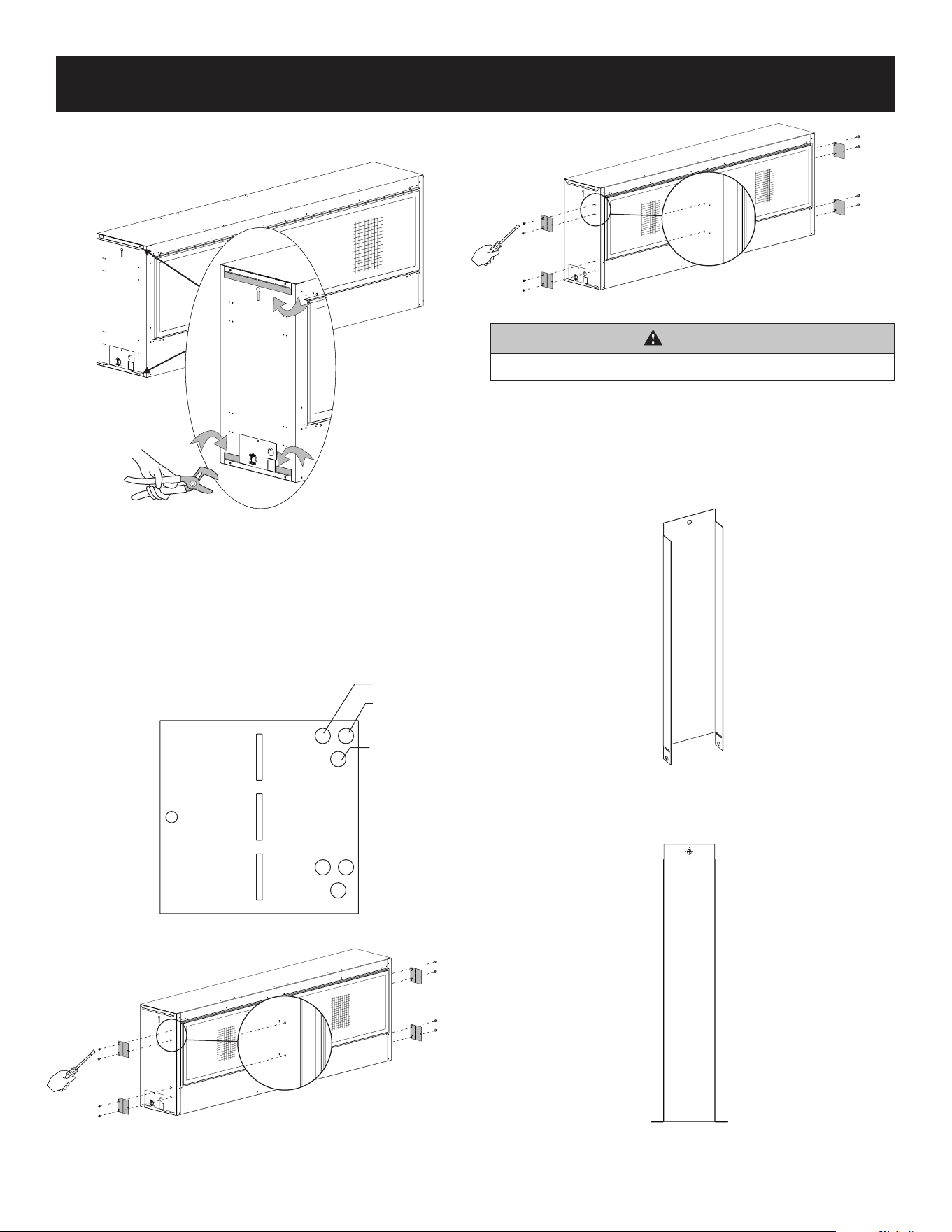
1. At the top and bottom of the replace, use pliers to bend
each side stando 90 degrees away from the cabinet. See
Figure 11.
Figure 11
Locate the nailing anges and stando brackets supplied with the
replace under the burner cover.
2. The holes in the nailing anges allow for dierent thickness
boards and depths of wall boards. See Figure 12. Install nailing
anges with two 10 x 12 screws (each) in pair of holes closer
to the face of the replace. Leave the nailing anges at until
after the replace is lifted into the framing.
See Figures 13 and 14.
5/8” BOARD
1/4” BOARD
½” BOARD
Figure 12
Figure 13 - OPTION 1
Figure 14 - OPTION 2
WARNING
TWO MAN LIFT RULE!
3. Repeat on opposite side.
4. Insert replace into enclosure. See Figure 14.
5. Level replace.
6. Bend nailing anges over side frames and attach.
7. Locate the steel stando brackets under the burner cover.
See Figure 15.
Figure 15
8. The brackets have a perforation at the bottom of each side.
Bend them at the perforation. See Figure 16.
Figure 16
46071-2-0725 Page 21
ADDING NAILING FLANGES AND STANDOFF BRACKETS
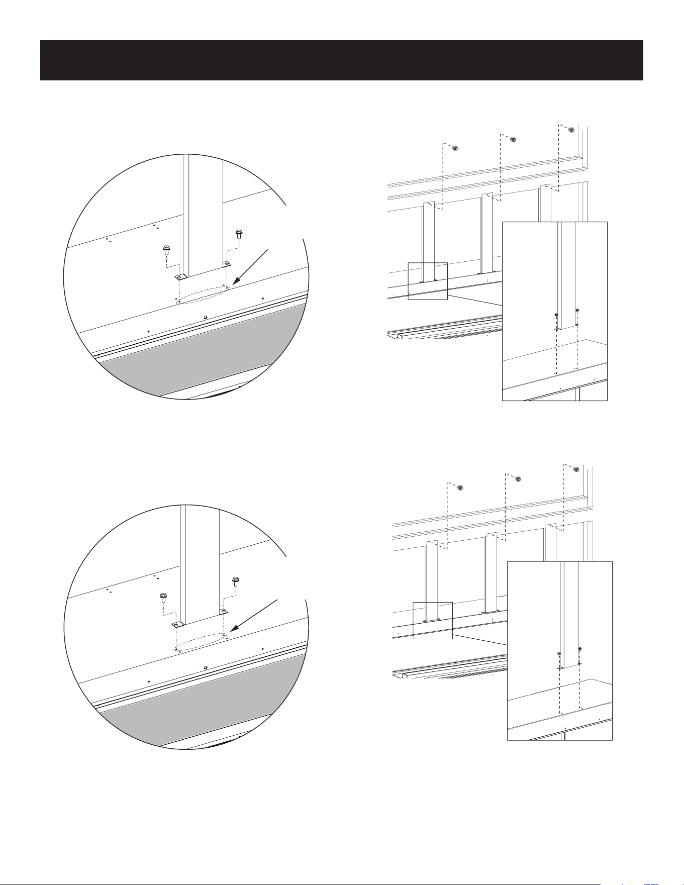
10a.
OPTION 1 - Secure stando brackets with drywall screws to the
framed opening above the replace as shown in Figure 19.
SCREW INTO
EACH BRACKET
Figure 19 - OPTION 1
10b.
OPTION 2 - Secure stando brackets with drywall screws to
the framed opening above the replace as shown in Figure 20.
SCREW INTO
EACH BRACKET
Figure 20 - OPTION 2
9a. OPTION 1 - Secure the brackets to the replace top with
screws. There are holes located in the top of the replace for
each stando bracket. The holes closer to the front edge of the
replace are for mounting non-combustible board around the
opening. Finishing OPTION 1. See Figure 17.
FOR USE WITH
NON-COMBUSTIBLE
BOARDS TO OPENING
FIREPLACE OPENING
TOP OF
FIREPLACE
Figure 17 - OPTION 1
9b. OPTION 2 - Secure the brackets to the replace top with
screws. There are holes located in the top of the replace for
each stando bracket. The holes back further from the front
edge of the replace are for mounting non-combustible board
to the top of the replace so that tile or stone can cover the
face. Finishing OPTION 2. See Figure 18.
FOR USE WITH
NON-COMBUSTIBLE
BOARDS TO TOP
OF FIREPLACE
FIREPLACE OPENING
TOP OF
FIREPLACE
Figure 18 - OPTION 2
FIREPLACE OPENING
FIREPLACE OPENING
TOP OF
FIREPLACE
TOP OF
FIREPLACE
FOR USE WITH
NON-COMBUSTIBLE
BOARDS TO
OPENING
FOR USE WITH
NON-COMBUSTIBLE
BOARDS TO TOP
OF FIREPLACE
Page 22 46071-2-0725
UTILITY INSTALLATION
-
VFLB
(
36,48
)
Remove barrier screen assembly from replace by lifting up slightly
and pulling out. Set aside. Remove the burner cover by lifting it up
and out. Set aside.
Bring the gas supply through the left or right side of the replace to
connect to the burner. See Figures 21 and 22. Consult the current
National Fuel Gas Code, ANSI Z223.1 CAN/CGA-B149 (.1 or .2)
installation code.
CAUTION
Never use plastic pipe. Check to conrm whether the local
codes allow copper or galvanized tubing.
NOTICE: Since some municipalities have additional local codes,
it is always best to consult the local authority and installation code.
The use of the following gas connectors is recommended:
— ANSI Z21.24 Fireplace Connectors of Corrugated Metal Tubing
and Fittings.
— ANSI Z21.45 Assembled Flexible Fireplace Connectors of Other
Than All-Metal Construction
The connectors specied by the National Fuel Gas Code may be used
if acceptable by the authority having jurisdiction. The Commonwealth
of Massachusetts requires that a exible replace connector cannot
exceed three feet in length.
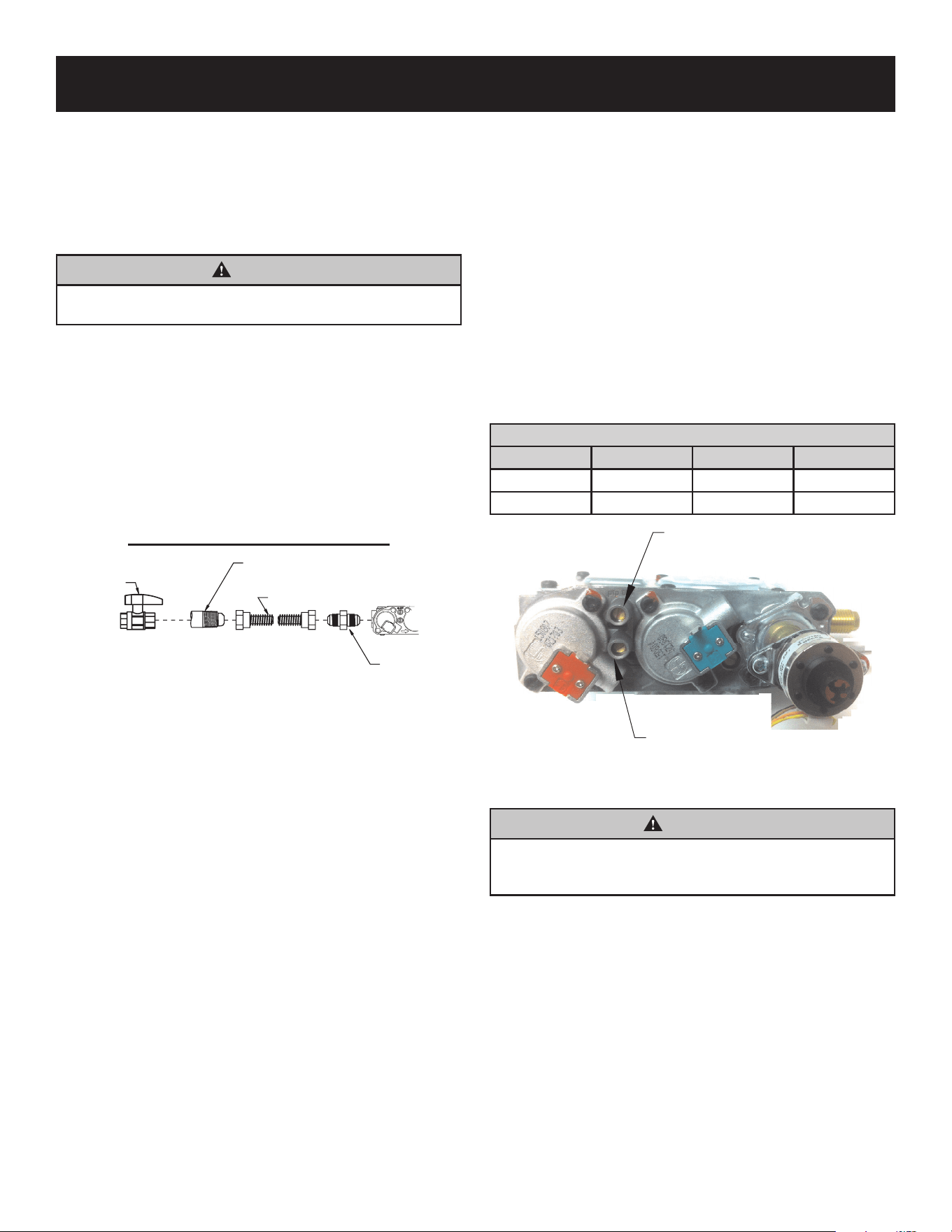
TEE HANDLE
FLEX TUBING
FLARE FITTING
FLEXIBLE GAS LINE CONNECTION
GAS SUPPLY
FLEXIBLE GAS LINE CONNECTION
Figure 21
INSTALLING THE MAIN GAS SHUT-OFF VALVE
Each replace should have its own manual gas shut-o valve
(included). Locate the manual main gas shut-o valve in the vicinity
of the replace easily accessible after assembly. Contact the local
authorized installer for installation or relocation when no shut-o
exists or the location is not adequate.
Compounds used on threaded joints of gas piping are resistant to
the action of liqueed petroleum gases. Gas lines must be checked
for leaks by the installer. A leak testing solution or soap should be
used for testing leaks on all exposed connections.
After testing is complete, all solutions should be cleaned o.
On unexposed connections, a pressure test should be made.
Never use an exposed ame to check for leaks. Fireplace must be
disconnected from piping at inlet of control valve and pipe capped
or plugged for pressure test. Never pressure test with replace
connected; control valve will sustain damage.
When using copper or ex connector use only approved ttings. The
replace and its individual shut-o valve must be disconnected from
supply piping system during any pressure testing of that system at
test pressures in excess of 1/2 psig (3.5kPa). The replace must be
isolated from the gas supply piping system by closing its individual
manual shut-o valve during any pressure testing of the gas supply
piping system at test pressures equal to or less than 1/2 psig (3.5kPa).
TESTING GAS SUPPLY PRESSURE
NOTICE: The gas controls are equipped with a captured screw-
type pressure test point. It is not necessary to provide a 1/8-inch
test point up stream of the control. Bleed gas line before testing
gas pressure. Check for leaks.
INTERMITTENT PILOT VALVES (VFLB(36,48)FP90)
Natural Gas will have a manifold pressure of approximately 3.5
inches w.c. at the pressure regulator outlet with the inlet pressure
to the pressure regulator from a minimum of 7.0 inches w.c. for the
purpose of input adjustment to a maximum of 10.5 inches w.c.
Propane Gas will have a manifold pressure approximately 10.0
inches w.c. at the pressure regulator outlet with the inlet pressure
to the pressure regulator from a minimum of 11.0 inches w.c. for
the purpose of input adjustment to a maximum of 13.0 inches w.c.
MILLIVOLT VALVES (VFLB(36,48)FP30)
Natural Gas will have a manifold pressure of approximately 3.5
inches w.c. for maximum input or 1.6 inches w.c. for minimum input
at the pressure regulator outlet with the inlet pressure to the pressure
regulator from a minimum of 4.5 inches w.c. for the purpose of input
adjustment to a maximum of 10.5 inches w.c.
Propane Gas will have a manifold pressure approximately 10.0
inches w.c. for maximum input or 6.3 inches w.c. for minimum input
at the pressure regulator outlet with the inlet pressure to the pressure
regulator from a minimum of 11.0 inches w.c. for the purpose of input
adjustment to a maximum of 10.0 inches w.c.
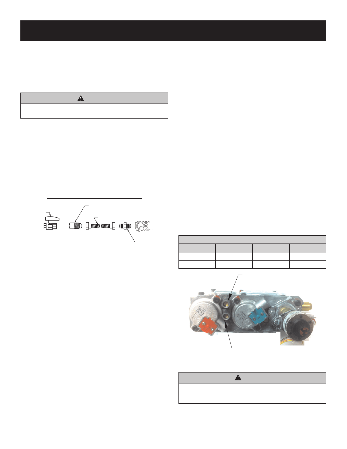
A test gage connection is located on the gas valve for measuring
gas pressure. The connections are two contained screws inside
tapered hose slip connections.
GAS PRESSURE (Inches Water Column)
Gas Type Maximum Minimum Manifold
Natural 10.5 7.0 3.5
Propane 13.0 11.0 10.0
MANIFOLD PRESSURE
TEST PORT
OUT
INLET PRESSURE
TEST PORT
IN
Figure 22
WARNING
If one of the procedures results in pressures in excess of
1/2 psig (14 inches w.c.) (3.5 kPa) on the replace gas valve,
it will result in a hazardous condition.
46071-2-0725 Page 23
UTILITY INSTALLATION
-
VFLB
(
60,72
)
Remove barrier screen assembly from replace by lifting up slightly
and pulling out. Set aside. Remove the burner cover by lifting it up
and out. Set aside.
Bring the gas supply through the left or right side of the replace to
connect to the burner. See Figures 23 and 24. Consult the current
National Fuel Gas Code, ANSI Z223.1 CAN/CGA-B149 (.1 or .2)
installation code.
CAUTION
Never use plastic pipe. Check to conrm whether the local
codes allow copper or galvanized tubing.
NOTICE: Since some municipalities have additional local codes,
it is always best to consult the local authority and installation code.
The use of the following gas connectors is recommended:
— ANSI Z21.24 Fireplace Connectors of Corrugated Metal Tubing
and Fittings.
— ANSI Z21.45 Assembled Flexible Fireplace Connectors of Other
Than All-Metal Construction
The connectors specied by the National Fuel Gas Code may be used
if acceptable by the authority having jurisdiction. The Commonwealth
of Massachusetts requires that a exible replace connector cannot
exceed three feet in length.
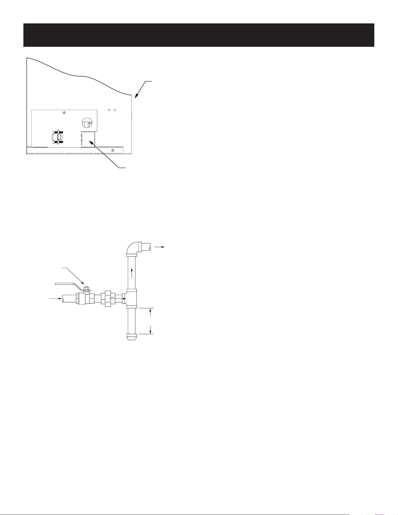
TEE HANDLE
FLEX TUBING
FLARE FITTING
FLEXIBLE GAS LINE CONNECTION
GAS SUPPLY
FLEXIBLE GAS LINE CONNECTION
Figure 23
INSTALLING THE MAIN GAS SHUT-OFF VALVE
Each replace should have its own manual gas shut-o valve.
Locate the manual main gas shut-o valve in the vicinity of the
replace easily accessible after assembly. Contact the local
authorized installer for installation or relocation when no shut-o
exists or the location is not adequate.
Compounds used on threaded joints of gas piping are resistant to
the action of liqueed petroleum gases. Gas lines must be checked
for leaks by the installer. A leak testing solution or soap should be
used for testing leaks on all exposed connections.
After testing is complete, all solutions should be cleaned o.
On unexposed connections, a pressure test should be made.
Never use an exposed ame to check for leaks. Fireplace must be
disconnected from piping at inlet of control valve and pipe capped
or plugged for pressure test. Never pressure test with replace
connected; control valve will sustain damage.
When using copper or ex connector use only approved ttings. The
replace and its individual shut-o valve must be disconnected from
supply piping system during any pressure testing of that system at
test pressures in excess of 1/2 psig (3.5kPa). The replace must be
isolated from the gas supply piping system by closing its individual
manual shut-o valve during any pressure testing of the gas supply
piping system at test pressures equal to or less than 1/2 psig (3.5kPa).
TESTING GAS SUPPLY PRESSURE
NOTICE: The gas controls are equipped with a captured screw-
type pressure test point. It is not necessary to provide a 1/8-inch
test point up stream of the control. Bleed gas line before testing
gas pressure. Check for leaks.
Natural Gas will have a manifold pressure of approximately 3.5
inches w.c. at the pressure regulator outlet with the inlet pressure
to the pressure regulator from a minimum of 7.0 inches w.c. for the
purpose of input adjustment to a maximum of 10.5 inches w.c.
Propane Gas will have a manifold pressure approximately 10.0
inches w.c. at the pressure regulator outlet with the inlet pressure
to the pressure regulator from a minimum of 11.0 inches w.c. for
the purpose of input adjustment to a maximum of 13.0 inches w.c.
A test gage connection is located on the gas valve for measuring
gas pressure. The connections are two contained screws inside the
tapered hose slip connections.
GAS PRESSURE (Inches Water Column)
Gas Type Maximum Minimum Manifold
Natural 10.5 7.0 3.5
Propane 13.0 11.0 10.0
MANIFOLD PRESSURE
TEST PORT
OUT
INLET PRESSURE
TEST PORT
IN
Figure 24
WARNING
If one of the procedures results in pressures in excess of
1/2 psig (14 inches w.c.) (3.5 kPa) on the replace gas valve,
it will result in a hazardous condition.
Page 24 46071-2-0725
UTILITY INSTALLATION
(
CONT'D
)
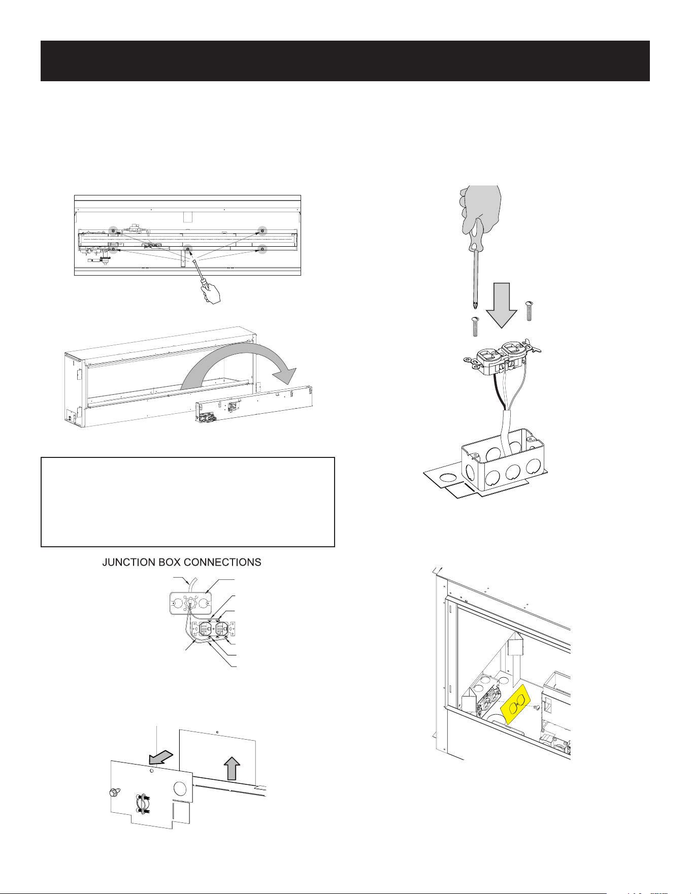
FRONT OF
FIREPLACE
GAS FLEX LINE
LEFT (VALVE) SIDE
OF FIREPLACE
Figure 25
Shut-o valve must be accessible after installation.
A gas valve and ground joint union should be installed in the gas line
upstream of the gas control to aid in servicing. The National Fuel
Gas Code requires that a drip leg be installed near the gas inlet.
See Figure 26. This should consist of a vertical length of pipe tee
connected into the gas line that is capped on the bottom in which
condensation and foreign particles may collect.
GAS SUPPLY PLUMBING
MANUAL
SHUT-OFF VALVE
GAS SUPPL
Y
INLET
DRIP LEG
3” MINIMUM
TO
CONTROL
VALVE
Figure 26
Empire recommends using a ange and key shut-o valve.
46071-2-0725 Page 25
UTILITY INSTALLATION
-
VFLB
(
60,72
)
SHOWN
(
CONT'D
)
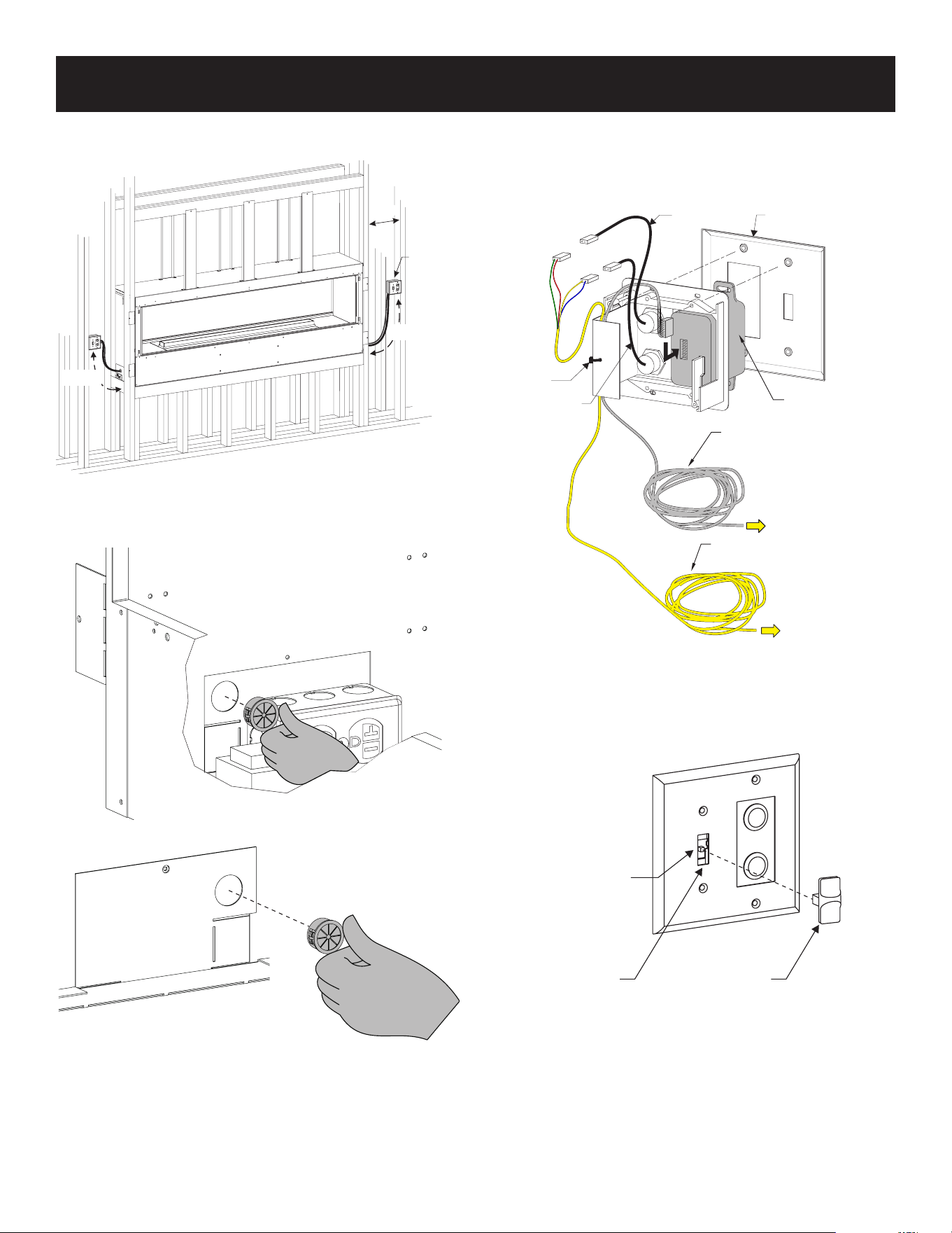
JUNCTION BOX WIRING INSTALLATION
A factory-installed junction box is located at the lower left corner
inside the rebox. For 120V electrical requirements install the
electrical receptacles into the junction box.
1. Remove the reective burner cover by lifting straight up and
then forward.
2. Remove burner box from replace. See Figures 27 and 28.
Figure 27
Figure 28
All wiring must be done by a qualied electrician and shall be in
compliance with all local, city and state building codes. Before
making the electrical connection, make sure the main power
supply is disconnected. The replace, when installed, must be
electrically grounded in accordance with local codes or, in the
absence of local codes, with the National Electrical Code ANSI/
NFPA 70 (latest edition).
BLACK (HOT)
BRASS SCREWS
JUNCTION BOX
GROUND
SILVER SCREWS
GREEN SCREW
WHITE
(NEUTRAL)
120 VOLT POWER SUPPLY
Figure 29
3. Remove the electrical access cover panel from the left end of
the replace. See Figure 29.
Figure 30
4. Run 14/2 Nm-B with ground or 12/2 Nm-B with ground wire
through the electrical access panel into the Junction box.
Attach the black wire to the receptacle, and the white wires to
the receptacle as shown in Figure 29. Secure the incoming
ground wire and green receptacle ground wires under the green
ground screw provided in the junction box.
5. Attach receptacle to junction box with screws provided. See
Figure 31.
Figure 31
6. Re-install the junction box into the rebox using the screw
removed in step 3. See Figure 30.
7. Install the Junction box cover. See Figure 32.
Figure 32
8. Connect ex line in burner box to inlet gas line.
9. Re-install burner box with screws removed earlier.
10. Check gas lines for leaks.
11. Plug AC adapter and LED transformer into junction box.
Page 26 46071-2-0725
UTILITY INSTALLATION
-
VFLB
(
60,72
)
SHOWN
(
CONT'D
)
12. Install the wall-mounted control box within 6 feet to the left
side or 4 feet from the right. See Figure 33.
WALL
MOUNT
CONTROL
BOX
6” MIN
4’ MAX
6’ MAX
Figure 33
13.
Install the provided plastic bushing in the opening where
the wires exit the replace. See Figure 34 (left side), or
Figure 35 (right side).
Figure 34
Figure 35
14.
Route the yellow LED wire harness with gray remote receiver
harness through the bushing. Mount the controls and connect
the wiring. Secure wiring with provided zip tie as shown. See
Figure 36.
REMOTE
SWITCH
COVER PLATE
YEL/BLUE
GRAY EXTENSION
WIRE
YELLOW EXTENSION
WIRE
RED/GREEN
TO FIREPLACE
CONTROL HARNESS
TO FIREPLACE
LED CONTROLS
LED SWITCH
ON/OFF
LED SWITCH
COLOR MODE
ZIP TIE
Figure 36
15.
Place batteries in remote receiver and in the remote control
using instructions provided. Place the switch slider to the
remote switch.
16.
Set the remote switch in wall box to remote. (center position)
See Figure 37.
REMOTE
POSITION
REMOTE
SWITCH
SWITCH
SLIDER
Figure 37
17. Verify remote is communicating with receiver. See Proame
control system page 41.
18. Test LEDs.
19.
Test burner for ignition. See lighting instructions on pages
38 and 39.
ATTENTION: Test all components prior to sealing and nishing
unit in the wall.
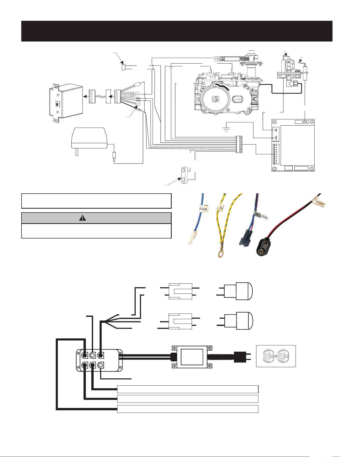
46071-2-0725 Page 27
UTILITY INSTALLATION
-
VFLB
(
60,72
)
SHOWN
(
CONT'D
)
WIRING DIAGRAM
(GND)
PILOT
GAS CONTROL
VALVE
ELECTRONIC
CONTROL MODULE
BLUE
WHITE
ORANGE
GREEN
YELLOW
BLACK
BLACK
AC/DC
POWER ADAPTOR
REMOTE RECEIVER
+ ON
REMOTE
- OFF
IGNITOR
SENSOR
RED
BLACK
EXTENSION HARNESS
NOT USED
NOT USED
NOT USED
YELLOW
RED
GREEN
BLUE
RED
BLACK
LED STRIP
LED STRIP
TRANSFORMER
CONTROL
MODULE
BLACK
BLACK
BLACK
TOP BUTTON
BRIGHTNESS
BOTTOM BUTT
ON
MODE
JUNCTION BOX
LED STRIP
COVER
CONNECTION
NOT IN USE
COVER
CONNECTION
NOT IN USE
Figure 39
WIRING DIAGRAM
Replace any damaged wiring with original wiring supplied by
Empire Comfort Systems.
CAUTION
Label all wires prior to disconnection when servicing controls.
Wiring errors can cause improper and dangerous operation.
Verify proper operation after servicing.
Figure 38
The wire terminals shown above in Figure 38 are not connected.

Page 28 46071-2-0725
NOTICE:
The steps on pages 29, 30 and 31 are for installation OPTION 1 - Clean Face.
This type of installation will allow for nishing around the replace face with high-temperature paint.
See pages 33, 34 and 35 for installing the replace for installation OPTION 2 - Flush Mount.
INSTALLATION OPTION 1
-
CLEAN FACE
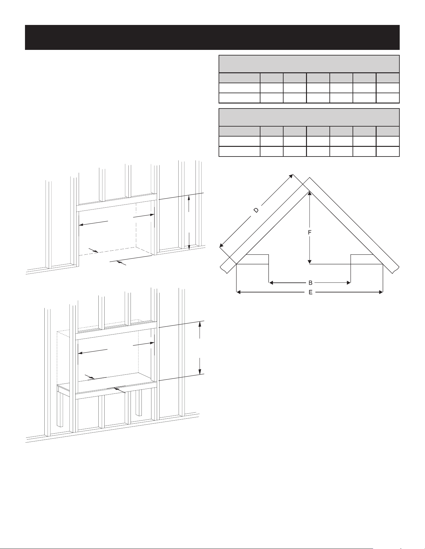
46071-2-0725 Page 29
1. Frame in rough opening.
• This replace is designed to be mounted on a hard, at
surface or raised platform.
• Use dimensions shown in Figure 40 for a conventional
rough opening.
• Use Figure 41 for an elevated installation. Provide support
to the bottom of the replace.
• Use dimensions shown in Figure 42 for corner rough
opening. Be sure to provide gas line and electrical power
for replace assembly.
2. Refer to Junction Box Wiring section on page 27 for details on
electrical requirements.
3. Verify gas and electrical lines are ready for replace installation.
See Gas Supply pages 22 and 23.
C
A
B
Figure 40 - Rough Opening for Installing in Wall
A
C
B
Figure 41 - Rough Opening for Elevated Installation
TABLE 3 - FRAMING DIMENSIONS (In Inches)
For Figures 40 - 42
Model A B C D E F
VFLB36FP90
41-5/8 42-1/2 11-1/2 45-1/8 63-3/4 31-7/8
VFLB48FP90
41-5/8 54-1/2 11-1/2 53 5/8 75-3/4 37-7/8
TABLE 3 - FRAMING DIMENSIONS (In Inches)
For Figures 40 - 42
Model A B C D E F
VFLB60FP90
41-5/8 66-1/2 11-1/2 62 87-3/4 43-7/8
VFLB72FP90
41-5/8 78-1/2 11-1/2 70-1/2
99-3/4
49-7/8
*
Minimum clearance with 1/2-inch non-combustible board over
face of replace.
Figure 42 - Rough Opening for Installing in Corner
OPTION 1
-
CLEAN FACE
(
NON
-
COMBUSTIBLE BOARD INSTALLATION
)
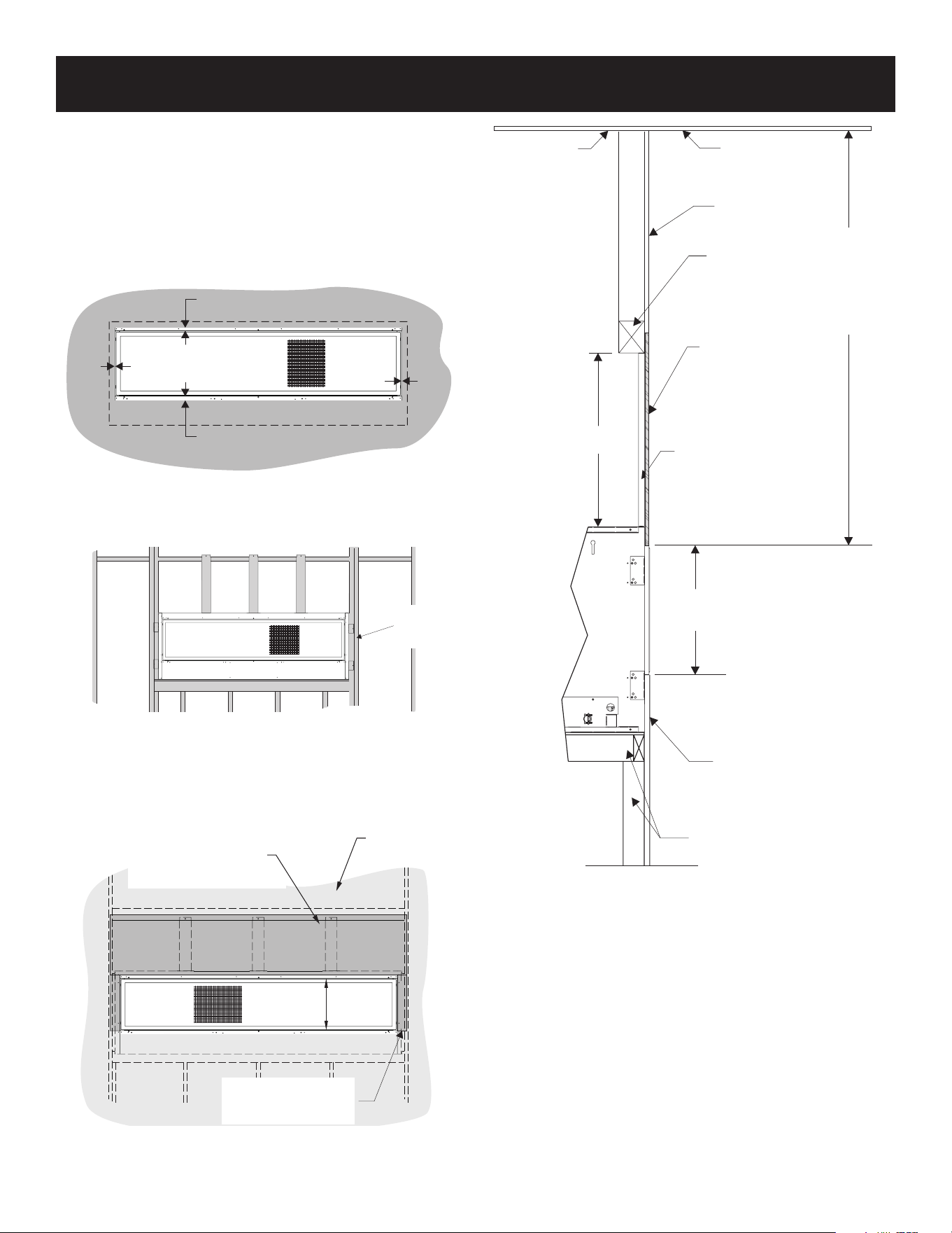
Page 30 46071-2-0725
NOTICE: If installing a decorative front, an oset between the
nishing materials and replace opening is required. Refer to the
installation instructions provided with the decorative front before
framing the opening.
• For installation of the DF361VBL-1, DF362VBL-1, DF481VBL-1,
DF482VBL-1, DF601VBL-1, DF602VBL-1, DF721VBL-1, and
DF722VBL-1 kits, 1/16-inch unnished space is required to
either side of the replace opening, and 7/16 inch unnished
space is required on top and bottom of the replace opening.
7/16”
7/16”
1/16”
1/16”
Figure 43
1. Screws are allowed in framing and top mounting brackets. No
screws are allowed into the replace. See Figure 44.
SCREWS
ALLOWED IN
SHADED AREA
Figure 44
2. Place upper non-combustible board above replace opening
to required gap, and secure with screws in approved area,
3.
Place side non-combustible boards to the side of each opening
to required gap and secure with screws in approved area.
FIREPLACE
OPENING
FINISHED
WALL
NON-COMBUSTIBLE
BOARD INSTALLED
OVER APPLIANCE OPENING
NON-COMBUSTIBLE
BOARD INSTALLED
ON BOTH SIDES
Figure 45
N-C
BOARD
FIREPLACE FACE
ON OMBUSTIBLE
INSTALLED
OVER
STANDOFFS
FRAMING
HEADER
FINISHED
PAINTED WALL
FINISHED
PAINTED WALL
FRAMING
FIREPLACE
OPENING
19”
CEILING
ENCLOSURE
TOP
36” MINIMUM
CLEARANCE
TO CEILING
AND
ENCLOSURE
TOP
Figure 46
NOTICE: Standos and non-combustible board shown for
reference.
OPTION 1
-
CLEAN FACE
(
NON
-
COMBUSTIBLE BOARD INSTALLATION
)
46071-2-0725 Page 31
OPTION 1
-
CLEAN FACE
(
NON
-
COMBUSTIBLE BOARD INSTALLATION
)
4. Install non-combustible board provided with the replace.
See Figure 45.
• Do not attach non-combustible board to the replace. Attach
non-combustible board only to framing and standos.
• Space non-combustible board 1/16 inch o of replace
opening anges to allow for expansion during operation.
• Predrill holes into non-combustible board and counter-sink.
• For best results treat non-combustible board and area around
the board with Kilz primer prior to applying adhesive or sealing
compound.
• Apply adhesive in joints between non-combustible board
panels.
• Use only high-temperature adhesive and high-temperature
paints rated for minimum 300
o
F with the non-combustible board.
5. Finish Wall.
• Use woven berglass joint tape and Durabond 45 joint
compound for best results when nishing non-combustible
panel and drywall joints around replace.
• Tile or non-combustible materials can be applied on top of the
non-combustible board and nished wall as their instructions
require.
NOTICE FOR FINISHING MATERIALS
The wall above the replace will become hot. Install the non-
combustible board supplied with the replace before adding
paint, tile or stone. Attach tile or other non-combustible products
to the replace face and to the non-combustible area using
adhesives designed for high-temperature applications. Follow the
manufacturer's instructions for application and curing times. Heat
from the replace may cause incorrectly installed materials to fail.
If you are painting above the replace, use a coating designed
for high temperature environments and follow the manufacturer's
instructions for surface preparation, application and curing. Heat
from the replace may cause incorrectly applied coatings to fail
or discolor.
Due to the variable properties of natural stone, the material may
have stress points that are unpredictable when installed above or
around the replace. These stress points may result in cracking of
the nish materials. Empire Comfort Systems is not responsible
for the nishing materials used with our replaces.
CAUTION
Failure to use a 300°F minimum adhesive may allow the
nishing material to fall.

Page 32 46071-2-0725
NOTICE:
The steps on pages 33, 34, and 35 are for installation OPTION 2 - Flush Mount.
This type of installation will allow for applying tile, marble, stone or other non-combustible materials over the face of the
replace cabinet up to the ange opening.
See pages 29, 30 and 31 for installation OPTION 1 - Clean Face.
INSTALLATION OPTION 2
-
FLUSH MOUNT
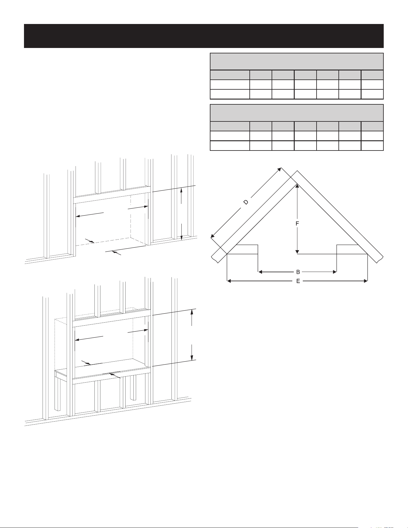
46071-2-0725 Page 33
1. Frame in rough opening.
• This replace is designed to be mounted on a hard,
at surface or raised platform.
• Use dimensions shown in Figure 47 for a conventional
rough opening.
• Use Figure 48 for an elevated installation. Provide
support to the bottom of the replace.
• Use dimensions shown in Figure 49 for corner rough
opening. Be sure to provide gas line and electrical power
for replace assembly.
2. Refer to Junction Box Wiring section on page 27 for details on
electrical requirements.
3.
Verify gas and electrical lines are ready for replace installation.
See Gas Supply pages 22 and 23.
C
A
B
Figure 47 - Rough Opening for Installing in Wall
A
C
B
Figure 48 - Rough Opening for Elevated Installation
TABLE 4 - FRAMING DIMENSIONS (In Inches)
For Figures 47 - 49
Model A B C D E F
VFLB36FP90
41-5/8 42-1/2 11-1/2 45-5/8 64-1/2 32-1/4
VFLB48FP90
41-5/8 54-1/2 11-1/2 64 75-3/4 45-1/4
TABLE 4 - FRAMING DIMENSIONS (In Inches)
For Figures 47 - 49
Model A B C D E F
VFLB60FP90
41-5/8 66-1/2 11 62-5/8 88-1/2 44-1/4
VFLB72FP90
41-5/8 78-1/2 11 71-1/8
100-1/2
50-1/4
* Minimum clearance with 1/2-inch non-combustible board over
face of replace.
Figure 49 - Rough Opening for Installing in Corner
FRAMING - CLEAN FACE
OPTION 2
-
FLUSH FACE
(
NON
-
COMBUSTIBLE BOARD INSTALLATION
)
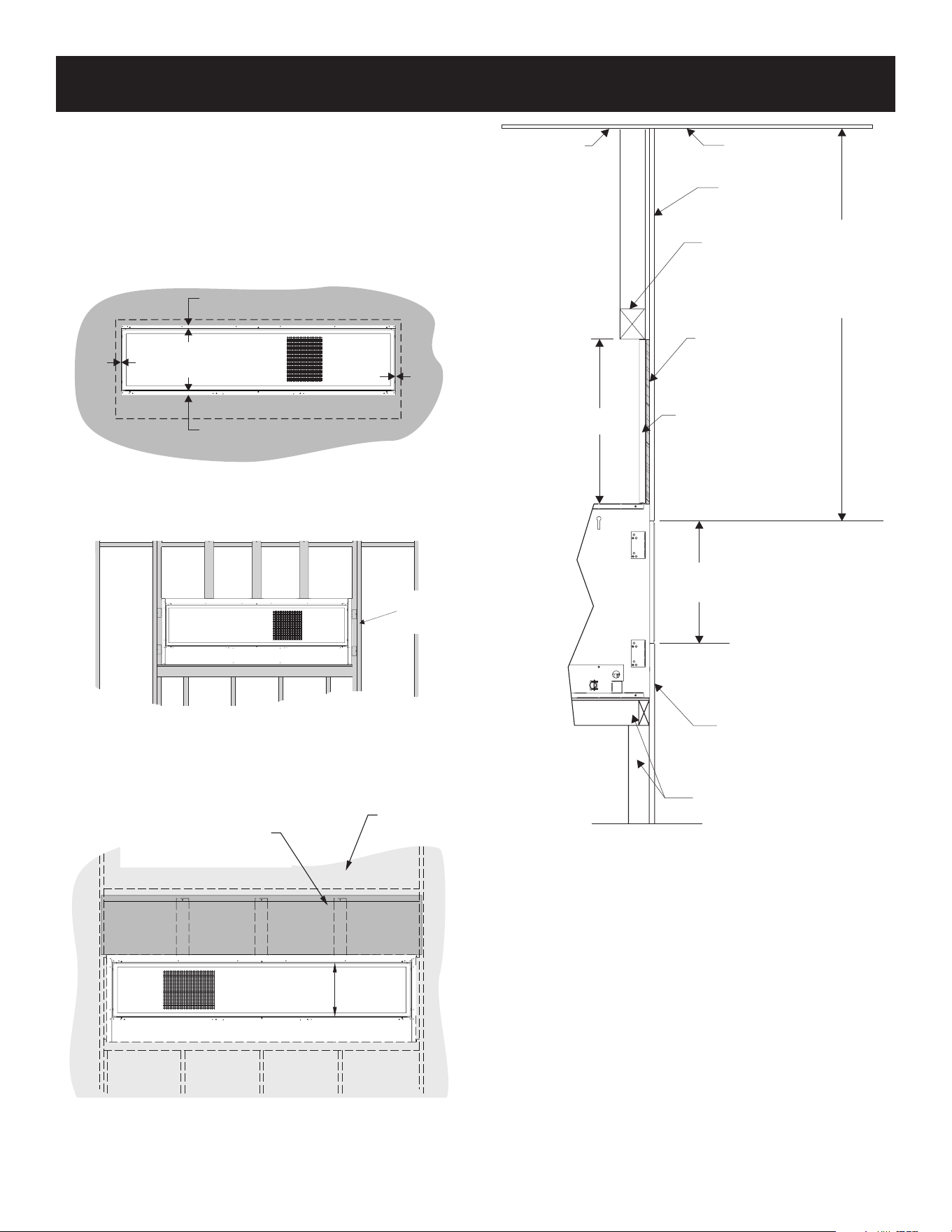
Page 34 46071-2-0725
NOTICE: If installing a decorative front, an oset between the
nishing materials and replace opening is required. Refer to the
installation instructions provided with the decorative front before
framing the opening.
• For installation of the DF361VBL-1, DF362VBL-1, DF481VBL-1,
DF482VBL-1, DF601VBL-1, DF602VBL-1, DF721VBL-1, and
DF722VBL-1 kits, 1/16-inch unnished space is required to
either side of the replace opening, and 7/16-inch unnished
space is required on top and bottom of the replace opening.
7/16”
7/16”
1/16”
1/16”
Figure 50
1. Screws are allowed in framing and top mounting brackets. No
screws are allowed into the replace face. See Figure 51.
SCREWS
ALLOWED IN
SHADED AREA
Figure 51
2. Place the non-combustible board above replace opening to
required height, and secure with screws in approved area,
3.
Side non-combustible boards not used in this application.
FIREPLACE
OPENING
FINISHED
WALL
NON-COMBUSTIBLE
BOARD INSTALLED
OVER APPLIANCE OPENING
Figure 52
N-C
BOARD
FIREPLACE FACE
ON OMBUSTIBLE
INSTALLED
OVER
FRAMING
HEADER
NC TILE OR
OTHER MATERIAL
FINISHED
PAINTED WALL
FRAMING
FIREPLACE
OPENING
19”
STANDOFFS
CEILING
ENCLOSURE
TOP
36” MINIMUM
CLEARANCE
TO CEILING
AND
ENCLOSURE
TOP
Figure 53
NOTICE: Standos and non-combustible board shown for reference.
OPTION 2
-
FLUSH FACE
(
NON
-
COMBUSTIBLE BOARD INSTALLATION
)
46071-2-0725 Page 35
OPTION 2
-
FLUSH FACE
(
NON
-
COMBUSTIBLE BOARD INSTALLATION
)
4. Install non-combustible board provided with the replace.
See Figure 52.
• Do not attach non-combustible board to the replace face. Attach
non-combustible board only to the framing and standos.
• Space non-combustible board 1/16 inch o of replace opening
anges to allow for expansion during operation.
• Predrill holes into non-combustible board and counter-sink.
• For best results treat non-combustible board and area around
the board with Kilz primer prior to applying adhesive or sealing
compound.
• Apply adhesive in joints between non-combustible board panels.
• Use only high-temperature adhesive and high-temperature
paints rated for minimum 300
o
F with the non-combustible board.
5. Finish Wall.
• Use woven berglass joint tape and Durabond 45 joint
compound for best results when nishing non-combustible
panel and drywall joints around replace.
• Tile or non-combustible materials can be applied on top
of the non-combustible board and nished wall as their
instructions require.
NOTICE FOR FINISHING MATERIALS
The wall above the replace will become hot. Install the non-
combustible board supplied with the replace before adding
paint, tile or stone. Attach tile or other non-combustible products
to the replace face and to the non-combustible area using
adhesives designed for high-temperature applications. Follow the
manufacturer's instructions for application and curing times. Heat
from the replace may cause incorrectly installed materials to fail.
If you are painting above the replace, use a coating designed
for high temperature environments and follow the manufacturer's
instructions for surface preparation, application and curing. Heat
from the replace may cause incorrectly applied coatings to fail
or discolor.
Due to the variable properties of natural stone, the material may
have stress points that are unpredictable when installed above or
around the replace. These stress points may result in cracking of
the nish materials. Empire Comfort Systems is not responsible
for the nishing materials used with our replaces.
CAUTION
Failure to use a 300°F minimum adhesive may allow the
nishing material to fall.
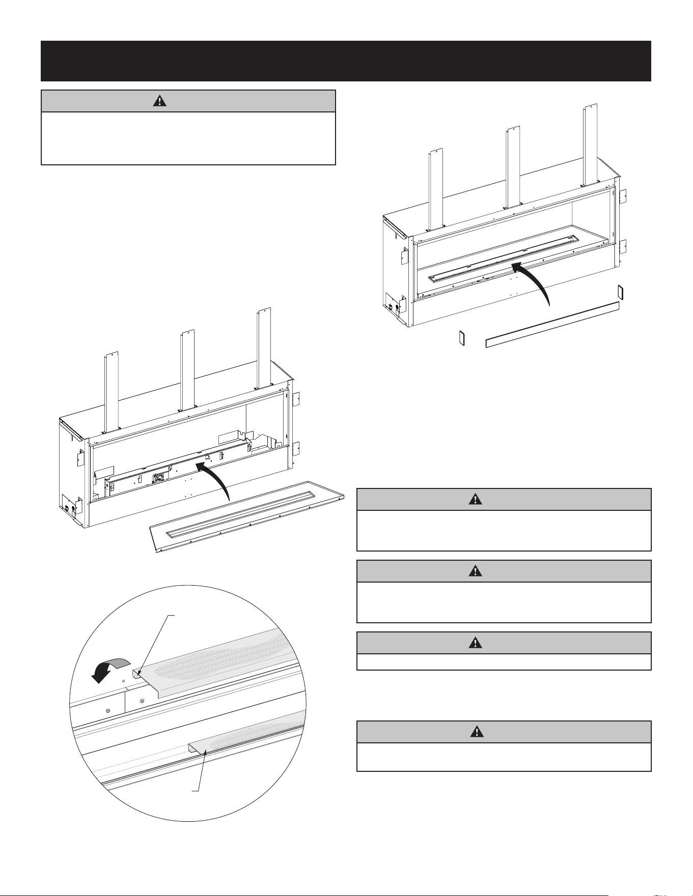
Page 36 46071-2-0725
COMPLETING INSTALLATION
WARNING
Failure to position the parts in accordance with the diagrams
and instructions below or failure to use only parts specically
approved for use with this replace may result in property
damage or personal injury.
NOTICE: During setup the burner may be operated with or without
the optional Decorative accessories.
1. If installing an optional decorative front, install it at this time.
Refer to the instructions provided with the decorative front kit.
2. If installing an optional liner, install it at this time. Refer to the
instructions provided with the liner kit.
3. If installing an optional light kit, install it at this time. Refer to
the instructions provided with the light kit.
4. Install the burner cover assembly as shown in Figure 54.
Figure 54
BOTTOM FLANGE
TO BACK OF
FIREPLACE
FRONT GLASS
SCREEN
Figure 55
5. Retrieve the 3 glass panels and install on front and both sides
of burner. See Figure 56.
LEFT
RIGH
T
CENTER
Figure 56
6.
If installing the optional log/rock set, refer to the log set
instruction manual for placing them around the burner.
7. If installing optional Decorative Glass, install it at this time.
NOTICE: VFLB36FP will accept 1.75 square feet of Decorative Glass
and VFLB48FP will accept 2.25 square feet of Decorative Glass.
NOTICE:
VFLB60FP will accept 5 square feet of Decorative Glass
and VFLB72FP will accept 6 square feet of Decorative Glass.
WARNING
Crushed glass must not be more than a single layer. Do
not use more glass than recommended. Using excess glass
may cause injury or property damage.
WARNING
Use only decorative rocks and glass designed for use in
a replace. Using other materials may cause a situation
where injury or property damage may occur.
WARNING
Never place media materials on or next to the burner.
The Decorative Glass options are available in various colors and
package sizes. Choose the size appropriate for the replace. See
list on page 8.
CAUTION
To prevent injury, use gloves and eye protection while
applying the decorative glass or droplets.
Application of the Decorative Glass or Rocks should only be
performed after the burner has been fully installed, secured and
tested for leaks.
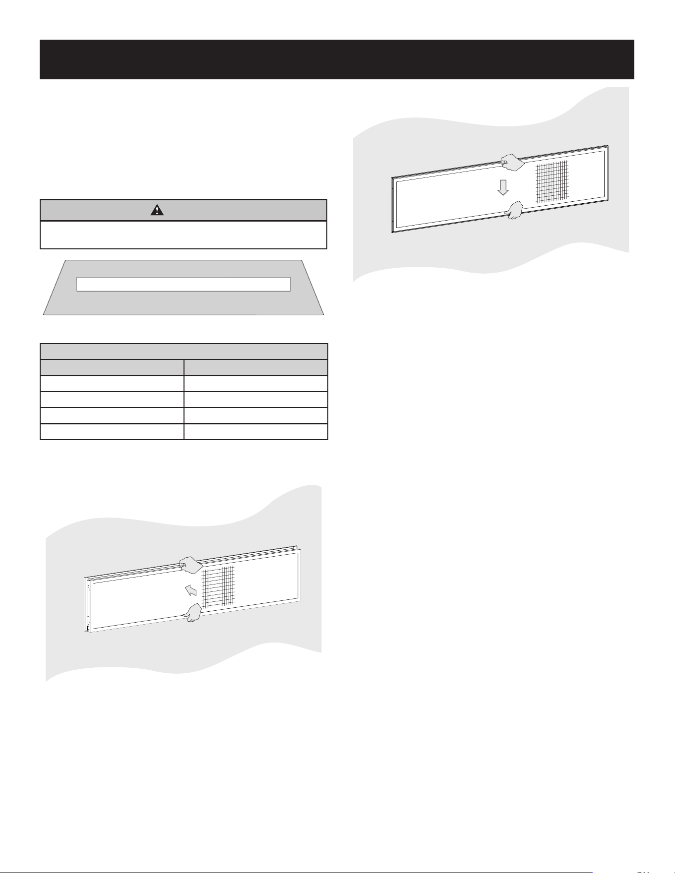
46071-2-0725 Page 37
COMPLETING INSTALLATION
(
CONT'D
)
8. Apply the accessory decorative glass or rocks to the shaded
area only. See Figure 57. Use enough to cover the area of the
replace, but do not allow the media to reach higher than the
ange surrounding the burner. Never place decorative media
inside the ange surrounding the burner itself.
This replace can use crushed glass, glass droplets (1/2 inch)
or glass drops (1 inch), or ceramic ber rocks and pebbles. Mix
colors and glass types, but do not exceed the recommended
amount of decorative media.
CAUTION
Glass or rocks must not be placed around the ends or over
the front edge of the burner assembly. Do not restrict air ow.
Figure 57
QUANTITY OF GLASS
Model Amount
VFLB36FP 1.75 square feet
VFLB48FP 2.25 square feet
VFLB60FP 5 square feet
VFLB72FP 6 square feet
9.
Replace the Barrier Screen onto the replace by lining up
the tabs with the slots in the rebox. Push the barrier screen
toward the unit and lower it slightly to lock in place. See
Figures 58-59.
Figure 58
Figure 59
10. Test replace using remote and show owner how to use the
remote. Show owner lighting instructions on page 35 for
Intermittent Pilot or 36 for Millivolt models.
11. Installation of replace is complete. Leave this manual with
owner.
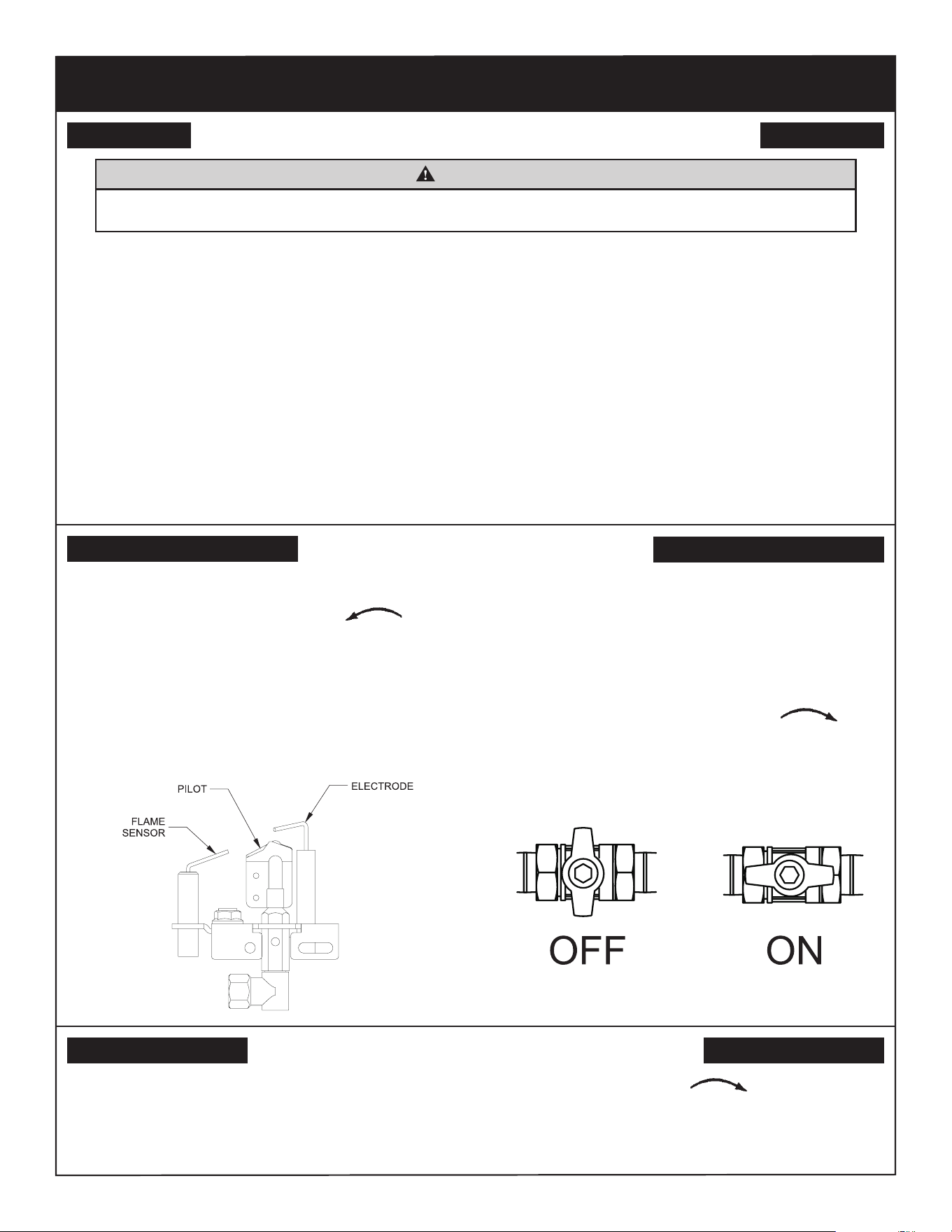
Page 38 46071-2-0725
TO TURN OFF GAS TO FIREPLACE
LIGHTING INSTRUCTIONS
WARNING
If you do not follow these instructions exactly, a re or explosion may result causing property damage,
personal injury or loss of life.
FOR YOUR SAFETY READ BEFORE LIGHTING
INTERMITTENT PILOT VALVE LIGHTING INSTRUCTIONS
1. STOP! Read the safety information above.
2. Turn OFF electric power to the appliance.
3. Turn gas shuto valve counterclockwise to
On position.
4. Wait ten (10) minutes to clear out any gas. Then smell for
gas, including near the oor. If you smell gas, STOP! Follow
B in the safety information above on this page. If you do not
smell gas, go to the next step.
5. Turn ON electric power to the appliance.
6. Find pilot. The pilot is next to the burner.
7. Turn main ame to on. If the pilot does not light within 60
seconds, stop and go to Step 5.
8.
Refer to remote control instructions for detailed information,
control features, and operation. NOTICE: There is a
CPI/IPI switch for a continuous standing pilot mode or
an intermittent pilot mode. See appliance manual for
location of this switch. If the pilot or burner does not stay
lit (in the standing pilot mode), stop and immediately call
a qualied service technician or gas supplier.
9. If the burner or pilot does not operate properly after
several tries, turn the gas valve clockwise to
OFF and call your service technician or gas supplier.
10. Operation of the gas valve is controlled by a manual on/
o switch or a hand held remote control. Refer to remote
instructions for detailed operation information.
GAS SHUT-OFF VALVE
1. Set REMOTE/OFF/ON switch to OFF.
2. Turn o all electric power to the appliance if service is to be
performed (if applicable).
3. Turn gas shut-o clockwise to OFF. Do not
force.
A. This appliance has a pilot which can be lit by hand or by
switching the remote receiver switch to the "ON" position.
When lighting the pilot, follow these instructions exactly.
B. BEFORE LIGHTING smell all around the appliance area for
gas. Be sure to smell next to the oor because some gas is
heavier than air and will settle on the oor.
WHAT TO DO IF YOU SMELL GAS
• Do not try to light any appliance.
• Do not touch any electrical switch;
• Do not use any phone in your building.
•
Immediately call your gas supplier from a neighbor's
phone. Follow the gas supplier's instructions.
•
If you cannot reach your gas supplier, call the re
department.
C. If applicable, use only your hand to turn the gas shut-
o valve handle. Never use tools. If the handle will not
turn by hand, don't try to repair it; call a qualied service
technician. Force or attempted repair may result in a re
or explosion.
D.
Do not use this appliance if any part has been under
water. Immediately call a qualied service technician
to inspect the appliance and to replace any part of the
control system and any gas control which has been
under water
.
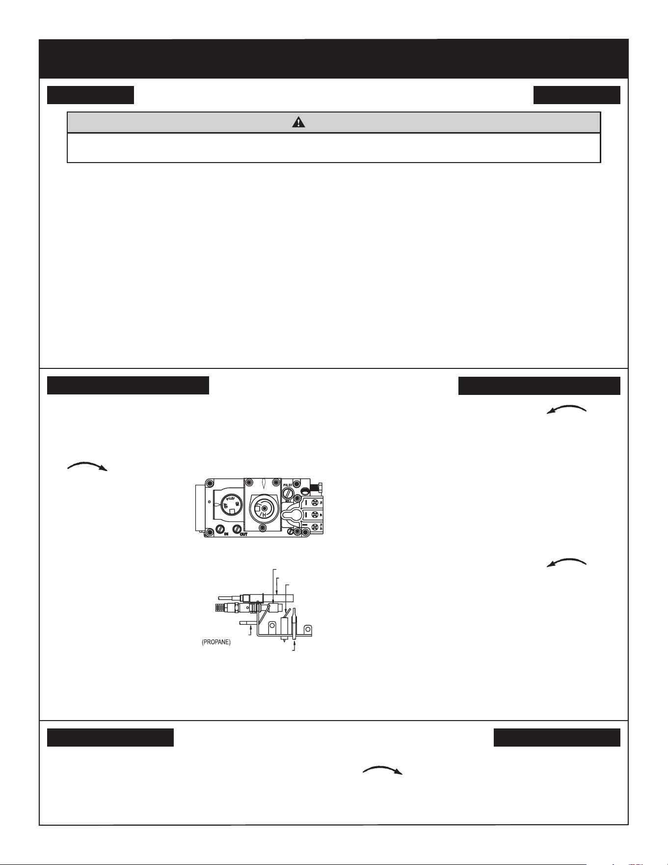
46071-2-0725 Page 39
MILLIVOLT CONTROL VALVE LIGHTING INSTRUCTIONS
TO TURN OFF GAS TO FIREPLACE
LIGHTING INSTRUCTIONS
WARNING
If you do not follow these instructions exactly, a re or explosion may result causing property damage,
personal injury or loss of life.
FOR YOUR SAFETY READ BEFORE LIGHTING
1. Open bottom louver assembly (if applicable).
2. Set REMOTE/OFF/ON switch to "OFF."
3. Turn o all electric power to the appliance if service is to
be performed (if applicable).
4. Push in gas control knob slightly and turn clockwise
to "OFF." Do not force.
5. Close bottom louver assembly (if applicable).
A. This appliance has a pilot which must be lighted by hand.
When lighting the pilot, follow these instructions exactly.
B. BEFORE LIGHTING smell all around the appliance area
for gas. Be sure to smell next to the oor because some gas
is heavier than air and will settle on the oor.
WHAT TO DO IF YOU SMELL GAS:
• Do not try to light any appliance.
• Do not touch any electrical switch;
Do not use any phone in your building.
• Immediately call your gas supplier from a neighbor's
phone. Follow the gas supplier's instructions.
•
If you cannot reach your gas supplier, call the re
department.
C. Use only your hand to push in or turn the gas control
knob. Never use tools. If the knob will not push in or
turn by hand, don't try to repair it; call a qualied service
technician. Force or attempted repair may result in a re
or explosion.
D. Do not use this appliance if any part has been under
water. Immediately call a qualied service technician
to inspect the appliance and to replace any part of the
control system and any gas control which has been under
water.
1. STOP! Read the safety information label.
2. Open bottom louver assembly (if applicable).
3. Set REMOTE/OFF/ON switch to "OFF."
4. Turn o all electric power to the appliance (if applicable).
5. Push in gas control knob slightly and turn clockwise
to "OFF."
NOTE: Knob cannot be
turned from "PILOT" to
"OFF" unless knob is
pushed in slightly. Do not
force.
6. Wait ten (10) minutes to
clear out any gas. Then
smell for gas, including
near the oor. If you smell
gas, STOP! Follow "B"
in the safety information
above. If you do not smell
gas, go to the next step.
7. Find pilot - Follow metal tube
from gas control. The pilot is
in front of the burner on the
right side.
GAS CONTROL KNOB
SHOWN IN “OFF” POSITION.
8. Turn gas control knob counterclockwise to
"PILOT."
9.
Push in control knob all the way and hold in. Repeatedly
push the Piezo Ignitor Button until the pilot is lit. Continue
to hold the control knob in for about one (1) minute after
the pilot is lit. Release knob, and it will pop back up. Pilot
should remain lit. If it goes out, repeat steps 5 through 9.
• If knob does not pop up when released, STOP and
IMMEDIATELY call a qualied service technician or
gas supplier.
• If the pilot will not stay lit after several tries, turn
the gas control knob to "OFF" and call your service
technician or gas supplier.
10. Turn gas control knob counterclockwise to
"ON."
11. Set REMOTE/OFF/ON switch to desired setting.
12. Turn on all electric power to the appliance (if applicable).
13. Close bottom louver assembly (if applicable).
GAS CONTROL KNOBGAS CONTROL KNOB
SHOWN IN "OFF" POSITION.SHOWN IN "OFF" POSITION.
THERMOCOUPLE
(NATURAL)
THERMOCOUPLE
(NATURAL)
ELECTRODEELECTRODE
PILOTPILOT
THERMOPILETHERMOPILE
REMOTEREMOTE
OFFOFF
ONON
THERMOCOUPLE
(LPG)
THERMOCOUPLE
(LPG)
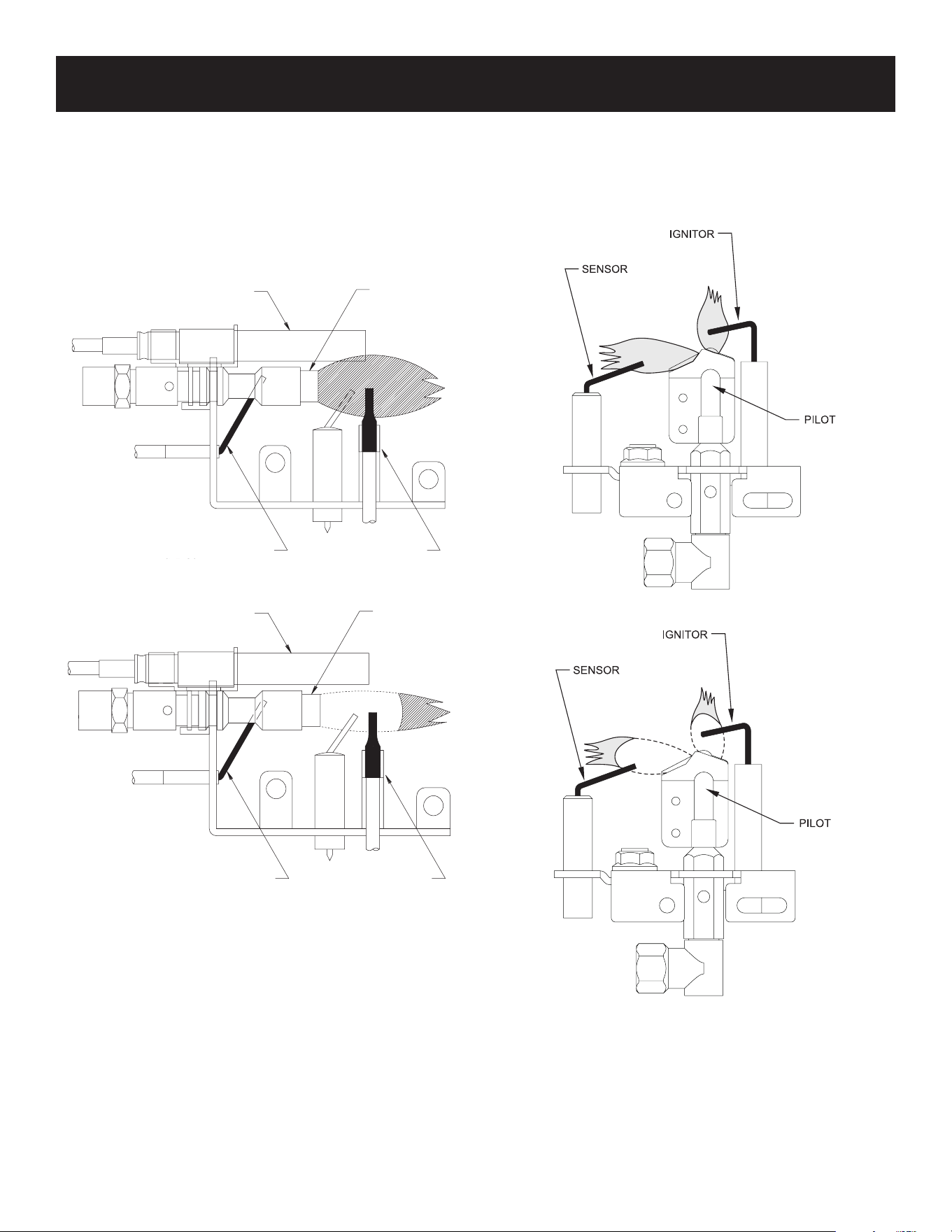
Page 40 46071-2-0725
Figures 60 and 62 shows a correct pilot ame pattern. The
correct ame will be blue and will extend beyond the ame sensor
or thermocouple. The ame will surround the ame sensor or
thermocouple just below the tip. A slight yellow ame may occur
where the pilot ame and main burner ame meet. Figures 61 and
63 shows an incorrect pilot ame pattern. The incorrect pilot ame
is not touching the ame sensor or thermocouple. This will cause
the ame sensor or thermocouple to cool. When the ame sensor
or thermocouple cools, the replace will shut down.
THERMOPILE
PILOT
THERMOCOUPLE
(LPG)
THERMOCOUPLE
(NATURAL)
Figure 60 - Correct Pilot Flame Pattern for MILLIVOLT
THERMOPILE
PILOT
THERMOCOUPLE
(LPG)
THERMOCOUPLE
(NATURAL)
Figure 61 - Incorrect Pilot Flame Pattern for MILLIVOLT
If pilot ame pattern is incorrect, as shown in Figure 61:
See Millivolt Troubleshooting, pages 54-55.
PILOT FLAME CHARACTERISTICS
Flames from the pilot (front center of burner) as well as the main
ame should be visually checked as the replace is installed.
In normal operation at full rate after 10 to 15 minutes, the ame
appearance should be sets of yellow ames.
NOTICE: All ames will be random by design, ame height will go
up and down.
Figure 62 - Correct Pilot Flame Pattern for INTERMITTENT PILOT
Figure 63 - Incorrect Pilot Flame Pattern for INTERMITTENT PILOT
If pilot ame pattern is incorrect, as shown in Figure 63:
• See Intermittent Pilot Troubleshooting, pages 51-53.
(PROPANE)
(PROPANE)
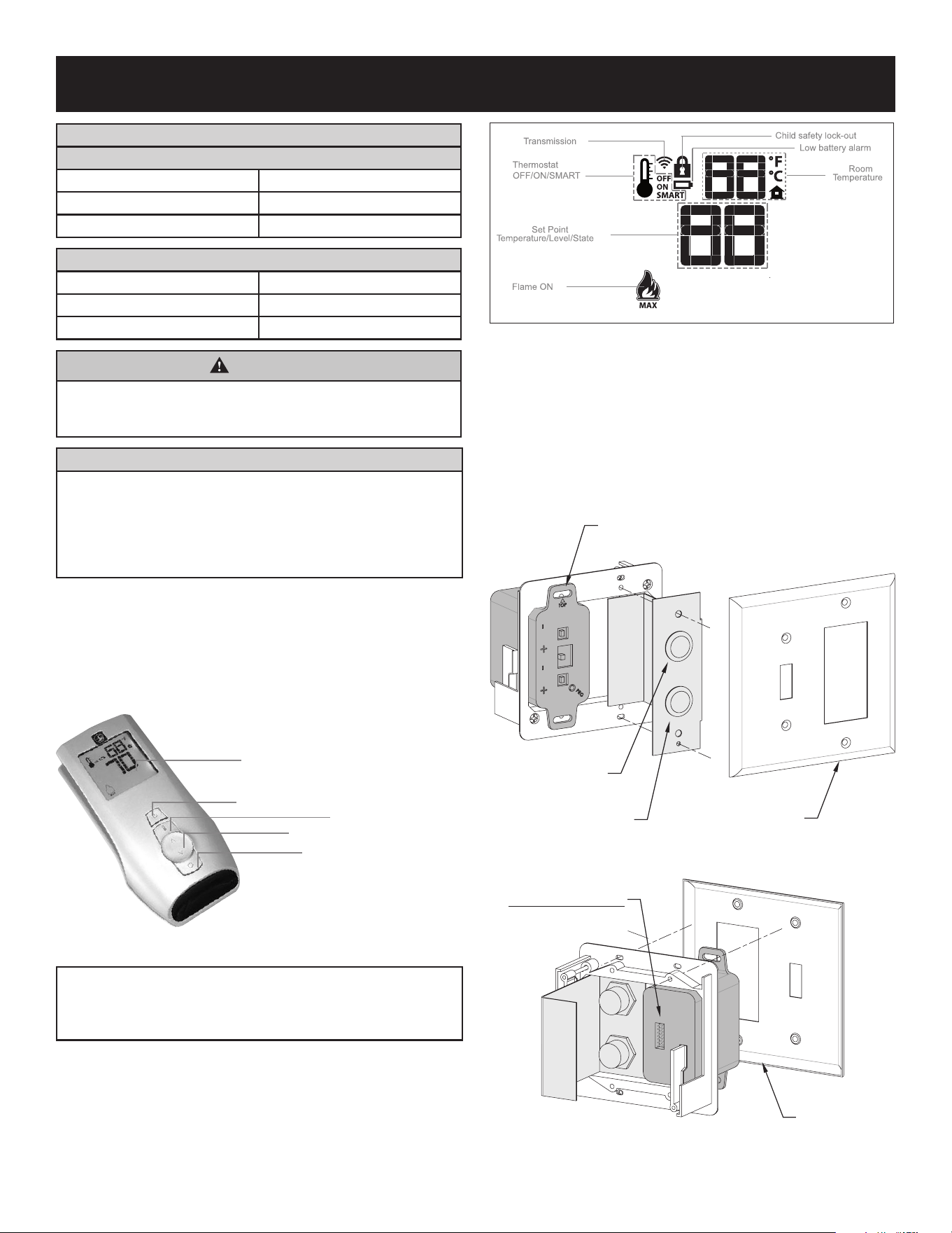
46071-2-0725 Page 41
PROFLAME
-
IP CONTROL SYSTEM
TECHNICAL DATA
Remote Control
Supply voltage
4.5 V (three 1.5 V AAA batteries)
Ambient temperature ratings 0-50°C (32 - 122°F)
Radio frequency 315 MHz
RECEIVER
Supply voltage 6.0 V (four 1.5 V AA batteries)
Ambient temperature ratings 0-60°C (32 - 140°F)
Radio frequency 315MHZ
WARNING
The transmitter and receiver are radio frequency devices.
Placing the receiver in or near metal may severely reduce
the signal range.
ATTENTION
• Turn o the main gas supply of the replace during
installation or maintenance of the receiver.
• Place the receiver's 3-position slider switch in the o
(down) position during installation or maintenance.
• Turn o main gas supply to the replace prior to removing
or reinserting the batteries in the receiver.
TRANSMITTER (REMOTE CONTROL WITH LCD DISPLAY)
The Proame Transmitter uses a streamline design with a simple
button layout and informative LCD display. See Figure 65.
The Transmitter is powered by 3 AAA type batteries. A Mode
Button is provided to Index between the features and a Thermostat
Button is used to turn on/o or index through thermostat functions.
See Figures 64 and 65.
Blue LCD Display
UP/DOWN Arrow Button
ON/OFF Button
THERMOSTAT
Button
MODE Button
Figure 64 - Proame Transmitter
The receiver may need to learn the transmitter. Press “learn”
button on the remote receiver followed by the power ON/
OFF button on the transmitter. A series of beeps will signal
communication has been made.
Figure 65 - Transmitter LCD display
RECEIVER
The Proame Receiver Figures 66 and 67 connects directly
to the gas valve and stepper motor with a wiring harness. The
Receiver is powered by 4 AA type batteries. The Receiver accepts
commands via radio frequency from the Transmitter to operate
the replace in accordance with the particular Proame system
conguration. The Receiver three position slider switch can be set
to one of three positions: Up for ON (Manual Override), middle for
Remote (Remote control) or down for OFF.
REMOTE
SWITCH
LED SWITCH
ON-OFF
LED SWITCH
COLOR MODE
COVER PLATE
Figure 66 - Proame Receiver Body Front
REMOTE SWITCH
14-PIN CONNECT
OR
COVER PLA
TE
Figure 67 - Proame Receiver Body Back

Page 42 46071-2-0725
INITIALIZING THE SYSTEM
Install 4 AA batteries into the receiver located behind the wall
plate. See Figure 67. Note the polarity of battery and insert into
the battery bay as indicated on the Battery cover (+/-). Place the 3
position slider switch in the Remote position.
Insert paper clip, or other similar object into the hole marked PRG
on the receiver front cover. The receiver will beep three times to
indicate that it is ready to synchronize with a transmitter. Install the
3 AAA type batteries in the transmitter. Push the ON button. The
receiver will beep four times to indicate the transmitter’s command
is accepted and sets to the particular code of that transmitter. The
system is now initialized.
TEMPERATURE INDICATION DISPLAY
With the system OFF, press the Thermostat Button and the Mode
Button at the same time. Verify that a C or F is visible to the right of
the Room Temperature display. See Figures 68 and 69.
Figure 68 - Fahrenheit
Figure 69 - Celsius
PROFLAME
-
IP CONTROL SYSTEM
(
CONT'D
)
TURN ON THE FIREPLACE
Press the ON/OFF Button. The Transmitter display will show all
active Icons on the screen. The replace main burner turns on.
A single beep from the Receiver will conrm reception of the
command.
TURN OFF THE FIREPLACE
Press the ON/OFF Button on the Transmitter. The Transmitter
LCD display will only show the room temperature and Icon. See
Figure 70. The replace burner turns o. A single beep from the
Receiver conrms reception of the command.
Figure 70
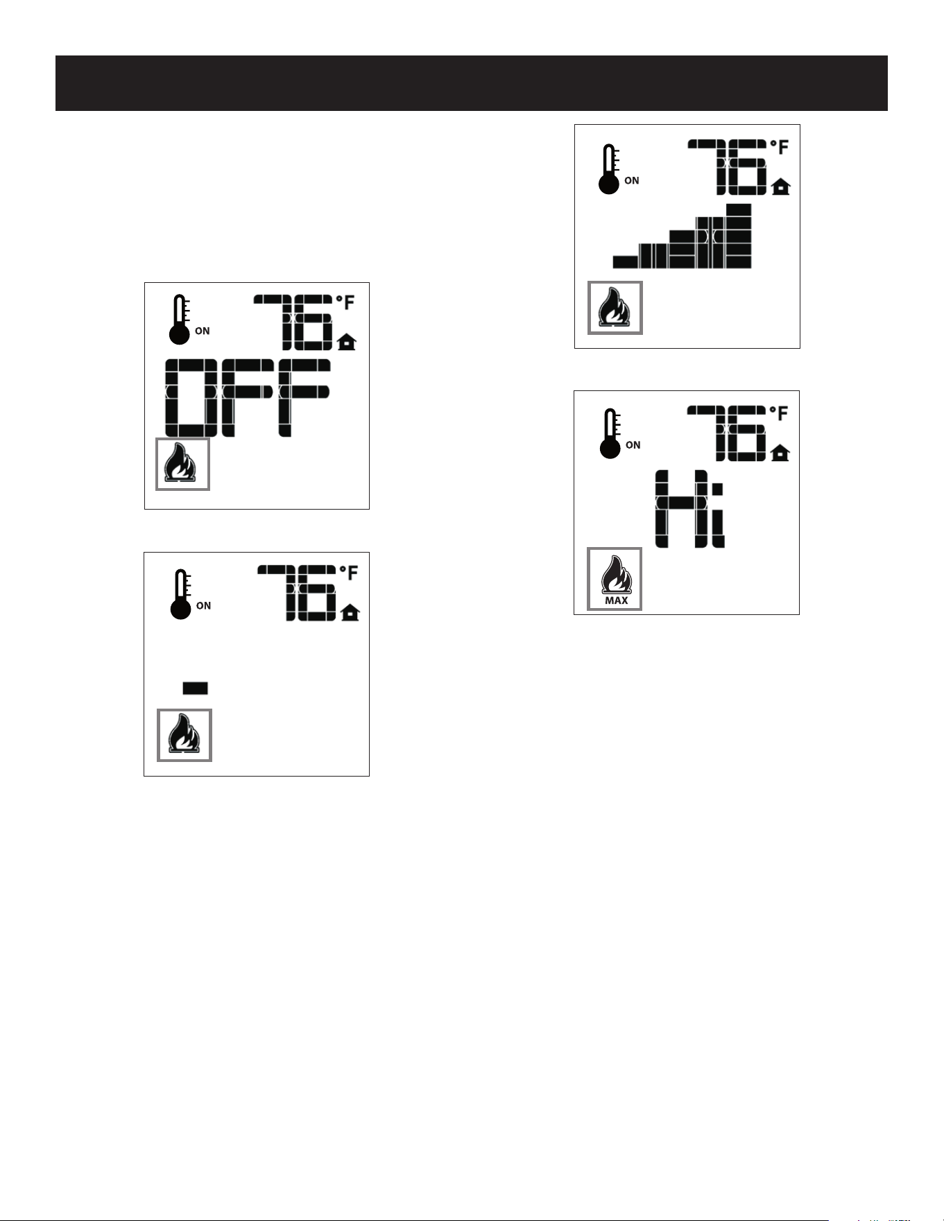
46071-2-0725 Page 43
PROFLAME
-
IP CONTROL SYSTEM
(
CONT'D
)
REMOTE FLAME CONTROL
The remote has six ame levels. With the system on, and the ame
level at maximum, each time you press the down arrow button will
reduce the ame height by one step until the ame is turned o.
Pushing the up arrow button will increase the ame height each
time it is pressed. Pushing the up arrow button while the system is
on but the ame is o will light the burner, the ame will come on in
the high position. See Figures 71 and 72. A single beep conrms
receipt of the command.
Figure 71
Figure 72
Figure 73
Figure 74
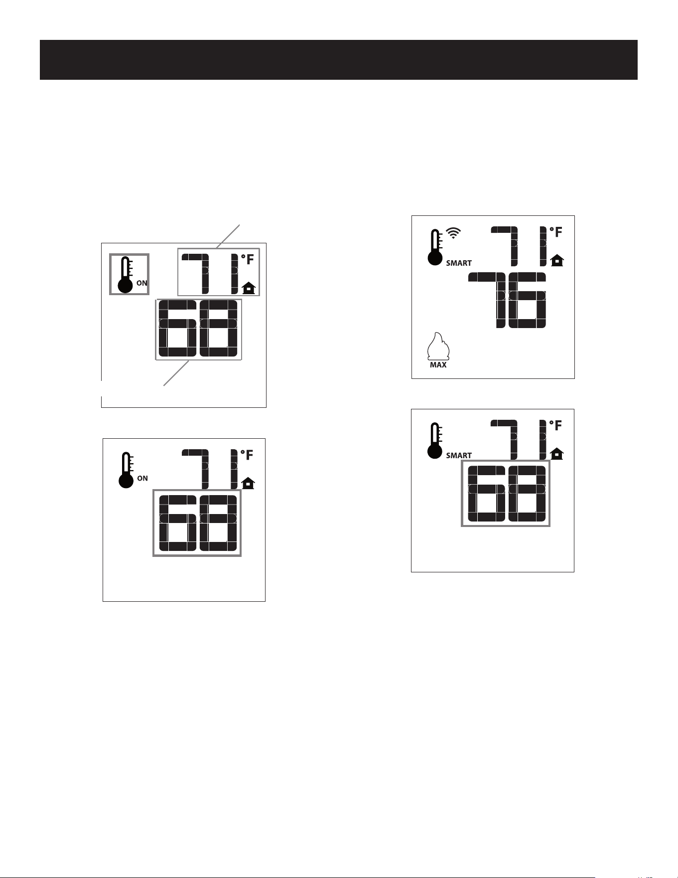
Page 44 46071-2-0725
THERMOSTAT OPERATION
The Remote Control can operate as a room thermostat. The
thermostat can be set to a desired temperature to control the
comfort level in a room.
To activate this function, press the Thermostat Button. See Figure
64. The LCD display on the Transmitter will change to show that the
room thermostat is ON and the set temperature is now displayed.
See Figures 76 and 77. To adjust the set temperature, press the
Up or Down Arrow Buttons until the desired set temperature is
displayed on the LCD screen of the Transmitter.
SET TEMPERATURE
ROOM TEMPERATURE
Figure 75
Figure 76
SMART THERMOSTAT (TRANSMITTER OPERATION)
The Smart Thermostat function adjusts the ame height in
accordance to the dierence between the set point temperature and
the actual room temperatures. As the room temperature gets closer
to the set point the Smart Function will modulate the ame down.
To activate this function, press the Thermostat Button Figure 64
until the word SMART appears to the right of the temperature bulb
graphic. See Figure 77. To adjust the set temperature, press the
Up or Down arrow Buttons until the desired set point temperature
is displayed on the LCD screen of the Transmitter. See Figure 78.
Figure 77
Figure 78
PROFLAME
-
IP CONTROL SYSTEM
(
CONT'D
)
ROOM
TEMPERATURE
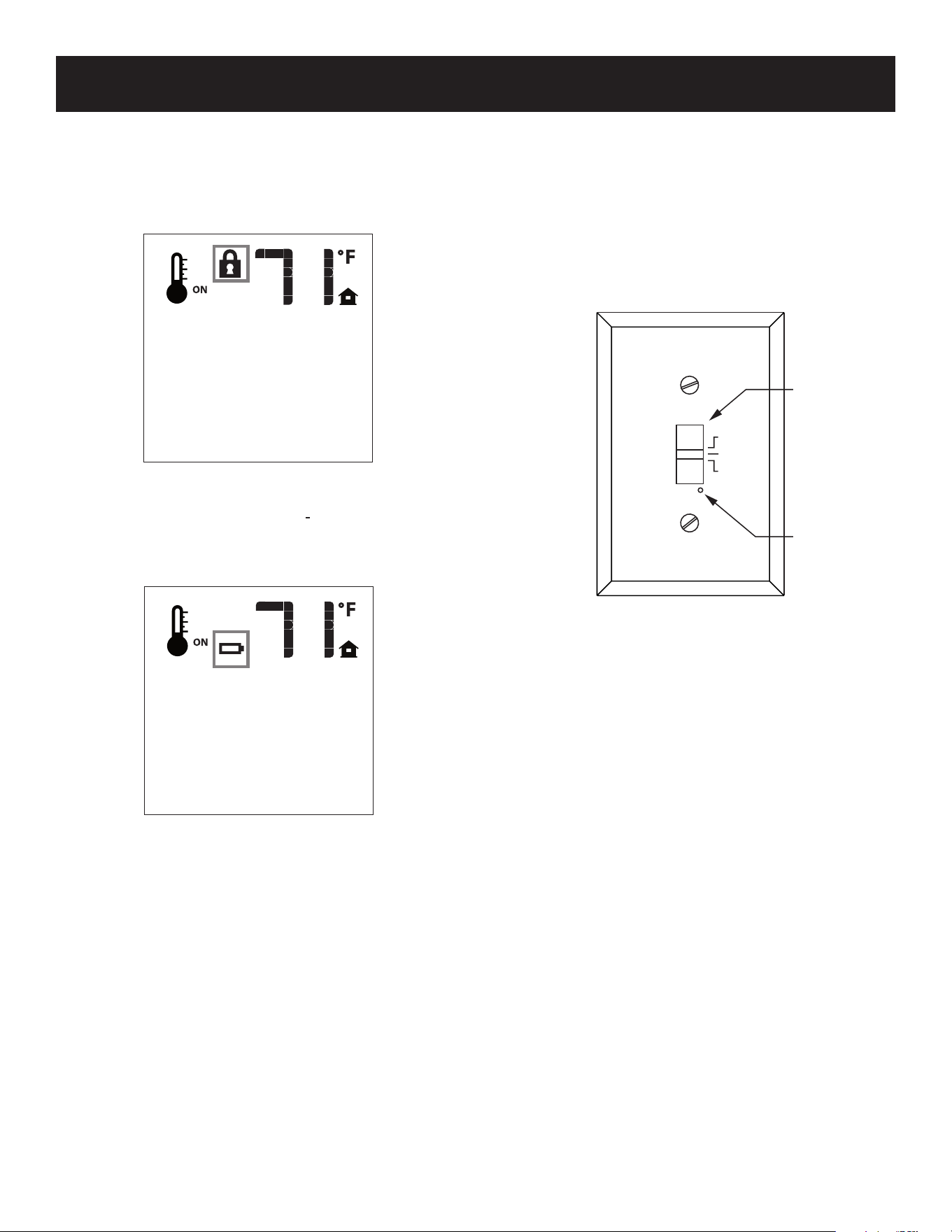
46071-2-0725 Page 45
PROFLAME
-
IP CONTROL SYSTEM
(
CONT'D
)
BUTTON LOCK
This function will lock the buttons to prevent unsupervised operation.
To lock the remote, press the MODE and the UP arrow button at
the same time. See Figure 79.
To unlock the remote, press the MODE and the UP arrow button
at the same time.
Figure 79
LOW POWER BATTERY INDICATOR TRANSMITTER
When the Transmitter batteries are low, a battery icon will appear on
the LCD display. See Figure 80. Replace the batteries and the Icon
will disappear. See page 49 to change batteries in remote switch.
Figure 80
RECEIVER
When the receiver batteries are low, no beep will be emitted when
it receives an ON/OFF command from the transmitter. Replace
the batteries.
MANUAL BYPASS OF THE REMOTE SYSTEM
If the batteries of the receiver or transmitter die, you can still
operate the replace manually by sliding the three position slider
switch on the wall control to the ON position.
This will bypass the remote control feature of the system and the
replace main burner will come on.
REMOTE
RECEIVER
SWITCH
- ON
- REMOTE
- OFF
PROGRAM
REMOTE
RECEIVER
SWITCH
- ON
- REMOTE
- OFF
PROGRAM
Figure 81
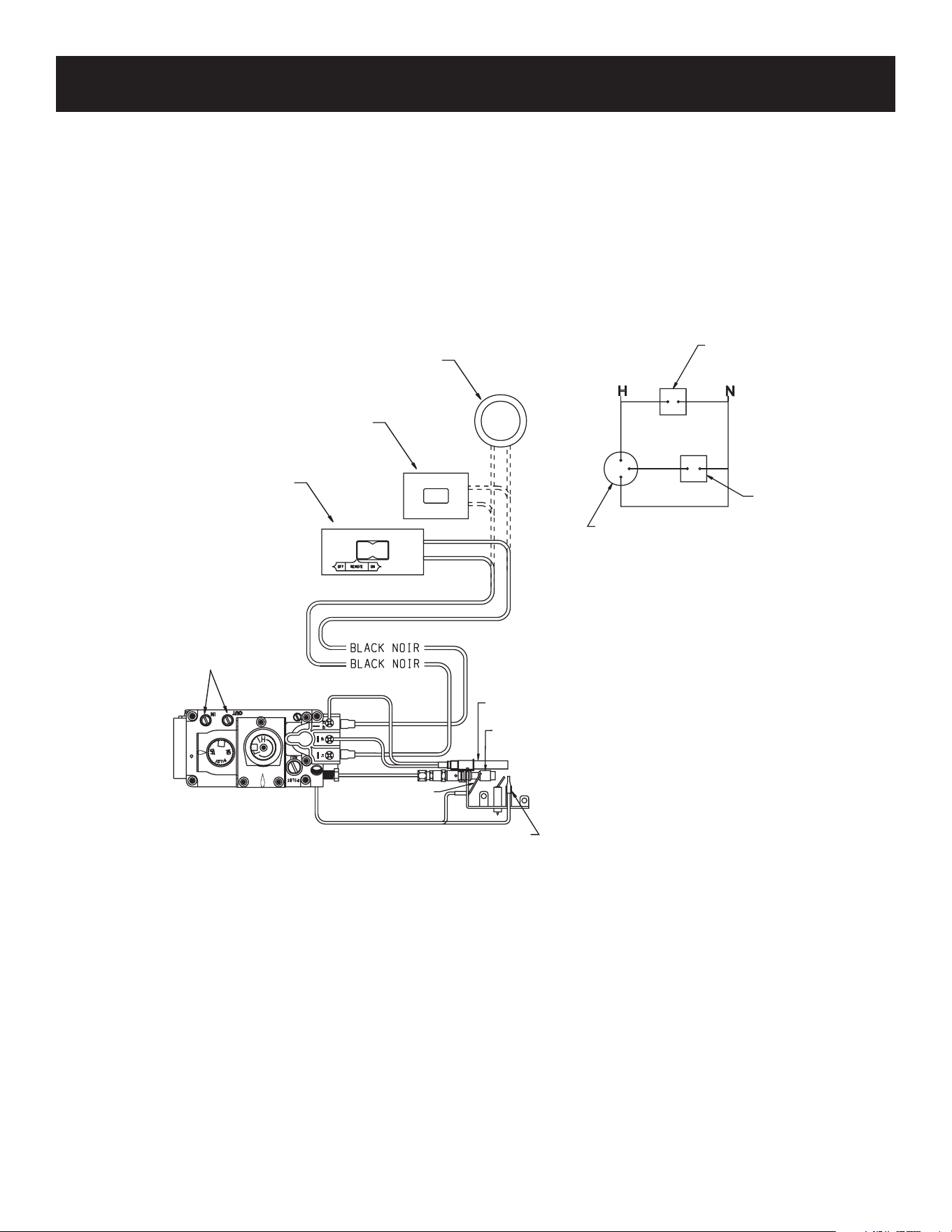
Page 46 46071-2-0725
Label all wires prior to disconnection when servicing controls. Wiring
errors can cause improper and dangerous operation. Verify proper
operation after servicing.
Millivolt thermopile is self powered, gas valve does not require 110
volts. Maximum length of 20 feet of 16 AWG to conductor wires is
to be used with all optional switches.
Check 750 Millivolt System Operation
Millivolt system and all individual components may be checked with
a millivolt meter 0-1000 MV range. The thermopile reading needs
to be between 325 and 400 millivolts.
Remote Receiver
Use the following steps to place the remote receiver adjacent to
the gas valve.
ATTENTION: The remote receiver bracket is not used in this
installation.
1. The remote receiver can not be placed beside the gas valve
and burner assembly.
2. When facing the replace, the remote receiver must be placed
to the left of the gas valve.
Refer to remote control installation and operating instructions for
more details on remote control.
WIRING DIAGRAM
-
MILLIVOLT CONTROL SYSTEM
WIRING DIAGRAM
H N
REMOTE CONTROL RECEIVER/
THERMOSTAT/CONTROLE E
DISTANCE DU RECEPTEUR
GAS VALVE
VALVE DE GAZ
(OPTIONAL) REMOTE/OFF/ON SWITCH
A DISTANCE/OUVERT/
FERME INTERRUPTEUR (FACULATIVE)
IF ANY OF THE ORIGINAL WIRE
AS SUPPLIED WITH THIS UNIT
MUST BE REPLACED, IT MUST BE
REPLACED WITH NUMBER 18, 150 C
WIRE OR ITS EQUIVALENT.
o
SI UN DES FILS ELECTRIQUES
ORIGINAUX, VENANT DU FABRICANT
AVEC CETTE UNITE, DOIT ETRE
REMPLACE, VOUS DEVEZ LE
REMPLACER AVEC UN FIL
ELECTRIQUE DE NUMERO 18,
150 C DU L’EQUIVALENT.
o
WIRING DIAGRAM
REMOTE CONTROL RECEIVER
(FACULTATIVE) CONTROLE E DISTANCE
DU RECEPTEUR
(OPTIONAL) WALL SWITCH
INTERRUPTEUR MURAL
(FACULTATIVE)
(OPTIONAL) THERMOSTAT
(FACULATIVE) THERMOSTAT
GAS VALVE
THERMOCOUPLE
(NATURAL)
THERMOCOUPLE
(LPG)
PILOT
VEILLEUSE
THERMOPILE
PRESSURE TAP
(PROPANE)
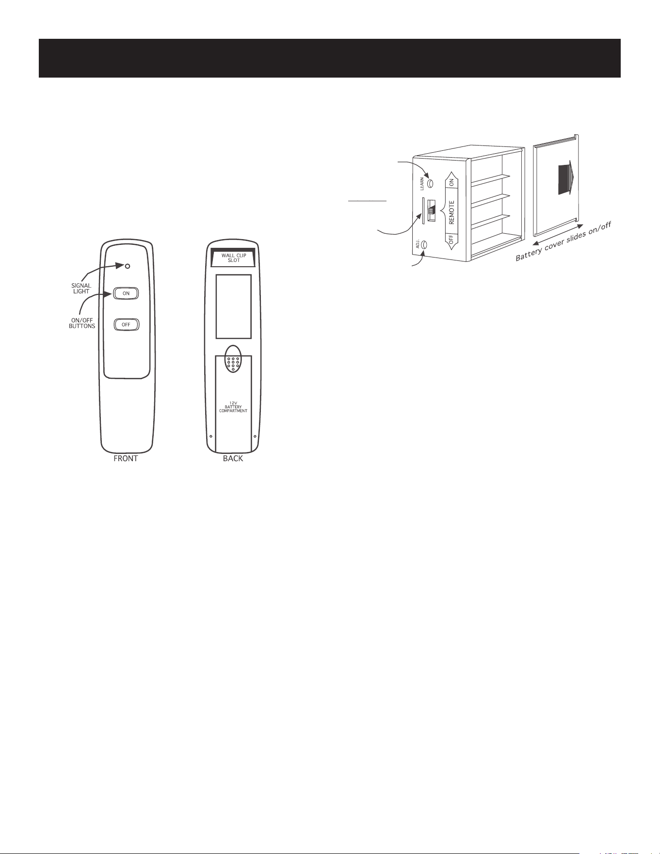
46071-2-0725 Page 47
FRBC
-
MILLIVOLT CONTROL SYSTEM
INSTALLATION AND OPERATING INSTRUCTIONS
INTRODUCTION
This remote control system was developed to provide safe,
reliable, and user-friendly remote control system for gas heating
replaces.
The system can be operated manually from the transmitter. The
system operates on one of 255 security codes that are programmed
into the transmitter at the factory.
The transmitter operates on a 12V battery (included) made
specically for remote controls and electronic lighters. Install the
12V battery supplied with the unit into the battery compartment.
TRANSMITTER
Figure 82
Always use alkaline batteries. They perform better and last longer.
The transmitter has ON and OFF functions that are activated by
pressing either button on the face of the transmitter. When a button
on the transmitter is pressed, a signal light on the transmitter
illuminates briey to verify that a signal has been sent. Upon initial
use, there may be a delay of three seconds before the remote
receiver will respond to the transmitter. This is part of the system’s
design. If the signal light does not illuminate, check the position of
the transmitter’s battery.
REMOTE RECEIVER
Figure 83
The remote receiver operates on 4 AA-size 1.5V batteries. It is
recommended that ALKALINE batteries be used for longer battery
life and maximum microprocessor performance. IMPORTANT:
New or fully charged batteries are essential for proper operation of
the remote receiver.
The remote receiver houses the microprocessor that responds to
commands from the transmitter to control system operation. The
remote receiver has a 3-position slide switch for selecting the
MODE of operation: ON/REMOTE/OFF
• With the slide switch in the ON position (toward the LEARN
button), the system will remain on until the slide switch is
placed in the OFF or REMOTE position.
• With the slide switch in the REMOTE position (centered),
the system will only operate if the remote receiver receives
commands from the transmitter.
• With the slide switch in the OFF position (away from the
LEARN button), the system is o.
• It is suggested that the slide switch be placed in the o
position if the homeowner will be away from home for
an extended period of time. If the remote receiver is
mounted out of children’s reach, placing the slide switch
in the OFF position also functions as a safety “lock-out”
by both turning the system o and rendering the remote
receiver inoperative.
REQUIRES 4
-
AA 1.5V
ALKALINE BATTERIES
FREQUENCY
ADJUSTING
ACCESS HOLE
LEARNING
BUTTON
SLIDE
SWITCH
ON
REMOTE
OFF
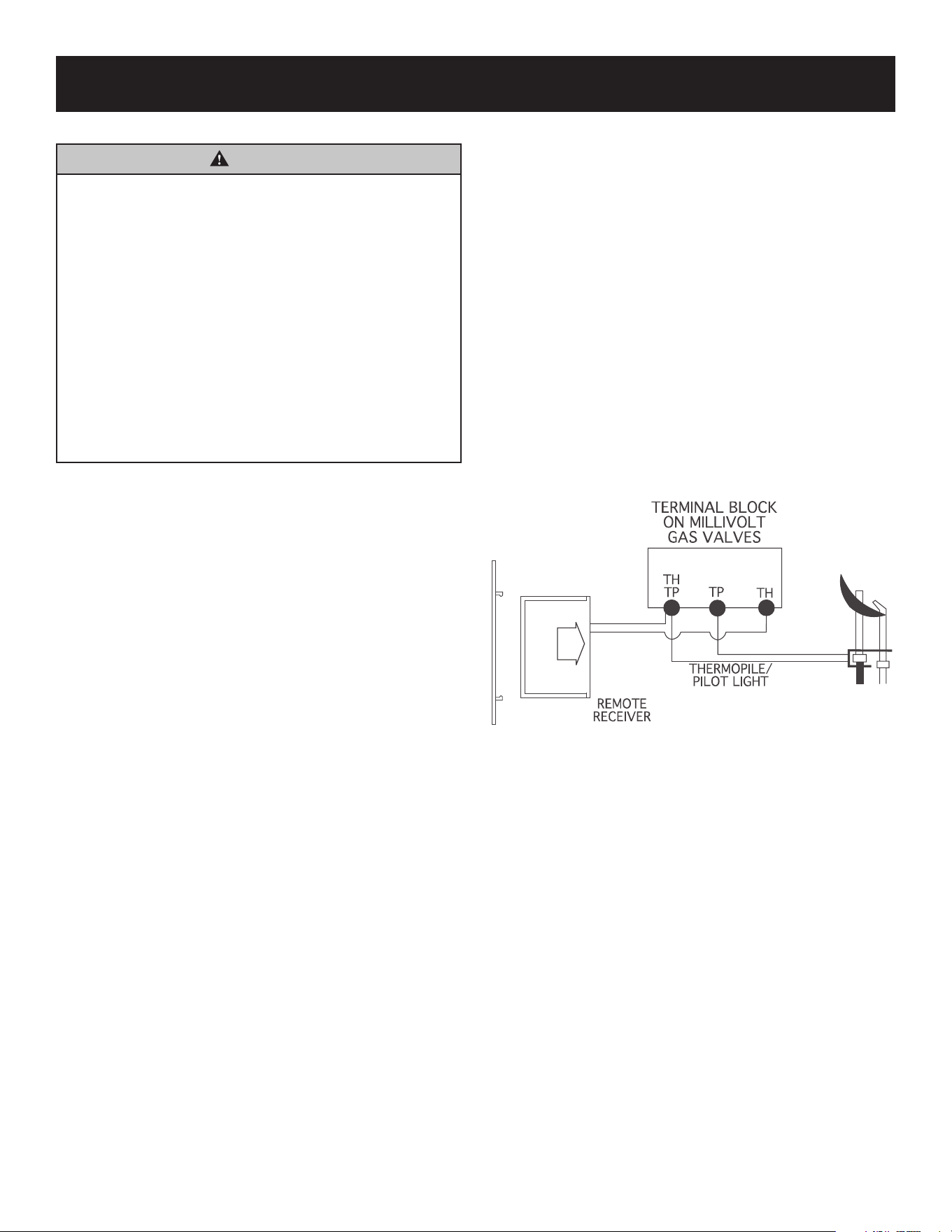
Page 48 46071-2-0725
FRBC
-
MILLIVOLT CONTROL SYSTEM
(
CONT'D
)
INSTALLATION
WARNING
This remote control system must be installed exactly
as outlined in these instructions. Read all instructions
completely before attempting installation. Follow instructions
carefully during installation. Any modications of the ECS
remote control or any of its components will void the warrant
and may be pose a re hazard.
Do not connect any gas valve or electronic module directly
to 110-120VAC power. Consult gas replace manufacturer’s
instructions and wiring schematics for proper placement
of all wires. All electronic modules are to be wired to
manufacturer’s specications.
The following wiring diagrams are for illustration purpose
only. Follow instructions from manufacturer of gas valve
and/or electronic module for correct wiring procedures.
Improper installation of electric components can cause
damage to electronic module, gas valve and remote receiver.
The remote receiver can be either wall-mounted in a standard
plastic switch box or placed on or near the replace hearth.
Preferably, the remote receiver should be wall-mounted in a plastic
switch box, as this will protect its electronic components from both
the heat produced by the gas replace and potential damage or
abuse that can occur if it is left exposed on the hearth.
PROTECTION FROM EXTREME HEAT IS VERY IMPORTANT.
Like any piece of electronic equipment, the remote receiver should
be kept away from temperatures exceeding 130° F inside the
receiver case. Battery life is also signicantly shortened if batteries
are exposed to high temperatures.
Make sure the remote receiver switch is in the OFF position. It is
recommended that 18 gauge solid or stranded wires (not included)
be used to make connections between the terminal wiring block on
the millivolt gas valve or electronic module and the wire terminals
on the remote receiver. For the best results, use 18 gauge solid or
stranded wire, with no splices and measuring no longer than 20 ft.
WIRING INSTRUCTIONS
A qualied electrician or a gas technician who is familiar with
the gas replace and gas valves that will be operated by this
remote should install the remote control system. Incorrect wiring
connections WILL cause damage to the gas valve or electronic
module operating the gas replace and may also damage the
remote receiver.
WIRING MILLIVOLT VALVES
The remote receiver is connected to the millivolt valve using the
TH (thermostat) terminals on the terminal block on the millivolt gas
valve.
Connect 18 gauge solid or stranded wires from the remote receiver
to the gas valve.
Operation of the remote receiver is similar to that of a thermostat
in that both turn the gas valve on and o based on input signals. A
thermostat’s input signals are dierent temperatures. The remote
receiver’s input signals come from the transmitter.
Connect each of the two wires leading from the TH terminals on
the millivolt gas valve to either of the two wire terminals on the
remote receiver. Normally it does not matter which wires go to
which terminal.
Figure 84
SYSTEM CHECK
Millivolt Valves
Light gas replace following the lighting instructions that came
with the replace. Conrm that the pilot ame is on; it must be in
operation for the main gas valve to operate.
• Slide the 3-position button on the remote receiver to the ON
position. The main gas ame (i.e., the re) should ignite.
• Slide the button to OFF. The ame should extinguish (the pilot
ame will remain on).
• Slide the button to REMOTE (the center position), then press
the ON button on the transmitter to change the system to ON.
The main gas ame should ignite.
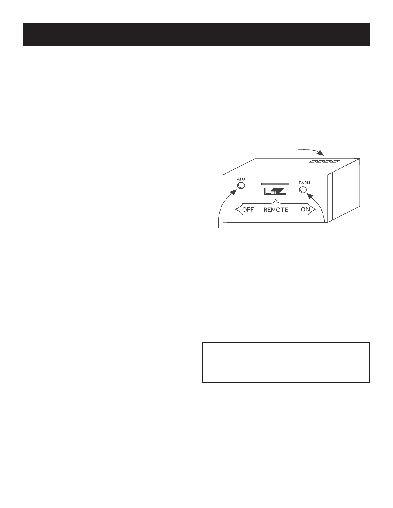
46071-2-0725 Page 49
GENERAL INFORMATION
Matching Security Codes
Each transmitter can use one of 255 unique security codes. It may
be necessary to program the remote receiver to LEARN the security
code of the transmitter upon initial use, if batteries are replaced,
or if a replacement transmitter is purchased from the dealer or the
factory. When matching security codes, be sure slide button on the
receiver is in the REMOTE position; the code will NOT “LEARN” if
the slide switch is in the ON or OFF position. Program the remote
receiver to LEARN a new security code by pushing and releasing
the learn button. A single "beep" will sound. Press the "ON" button
on the remote control, until three "beeps" sound. The three "beeps"
are the signal that the receiver has learned the new code. When an
existing receiver is matched to a new transmitter, the new security
code will override the old one.
The microprocessor that controls the security code matching
procedure is controlled by a timing function. If matching the
security code on the rst attempt was unsuccessful, wait 1-2
minutes before trying again – this delay allows the microprocessor
to reset its timer circuitry – and try up to two or three more times.
BATTERY LIFE
Life expectancy of the alkaline batteries is longer and performance
better than other batteries. Check and replace all batteries
annually. When the transmitter no longer operates the remote
receiver from a distance it did previously (i.e., the transmitter’s
range has decreased) or the remote receiver does not function at
all, the batteries should be checked. It is important that the remote
receiver batteries are fully charged and provides continuous
output voltage of a least 5.3 volts. The length of the wire between
the remote receiver and gas valve directly aects the operating
performance of the remote system. The longer the wire, the more
battery power is required to deliver signals between the remote
receiver and the gas valve. Recommended length is no longer
than 20 feet. The transmitter should operate with as little as 5.0
volts battery power.
TROUBLE SHOOTING
If problems with the replace system occur, the cause may be
with the replace itself or it could be with the ECS remote. Review
the replace manufacturer’s operation manual to make sure all
connections are properly made. Then check the operation of the
ECS remote in the following manner:
• Make sure the batteries are correctly installed in the
RECEIVER. One reversed battery will keep receiver from
operating properly.
• Check battery in Transmitter to make sure contacts are
touching (+) and (-) ends of battery. Bend metal contacts in
for tighter t.
• Be sure RECEIVER and Transmitter are within 20’-25’
operating range.
• Keep RECEIVER from temperatures exceeding 130° F.
Battery life shortened when ambient temperatures are above
130° F.
• If RECEIVER is installed in tightly enclosed metal surround,
the operating distance will be shortened.
RECEIVER ADJUSTMENT – RECOMMENDED ADJUSTMENT
NOTE: The slide button, White or Black, covers the ADJ access
hole when installed.
A. To adjust at the receiver, use a small slotted screwdriver. Turn
the adjustment screw counter-clockwise about 5 degrees
or a maximum of 1/8 turn. This should correct the distance
problem.
B. If that does not correct the problem, return adjustment screw
to original position and then turn adjustment screw clockwise.
This adjustment is like tuning a radio. If continued to be turned
in either direction, the adjustment screw will go past the proper
setting (tuning).
REMOTE RECEIVER
Figure 85
SPECIFICATIONS
Batteries:
• Transmitter 12V (A23)
• Remote Receiver
• 6V - 4ea. AA1.5 Alkaline
FCC ID No.’s: transmitter - K9L1002TX;
Receiver - K9L3001RX
Operating Frequency: 303.875MHZ
Canadian ISC ID No.’s: transmitter - 2439 102 728;
Receiver - 2439 102 728A
FCC REQUIREMENTS
NOTE: The Manufacturer Is Not Responsible For Any Radio
Or Tv Interference Caused By Unauthorized Modications To
This Equipment. Such Modications Could Void The User’s
Authority To Operate The Equipment.
FRBC
-
MILLIVOLT CONTROL SYSTEM
(
CONT'D
)
LEARING
BUTTON
FREQUENCY ADJUSTING
ACCESS HOLE
WIRE TERMINALS
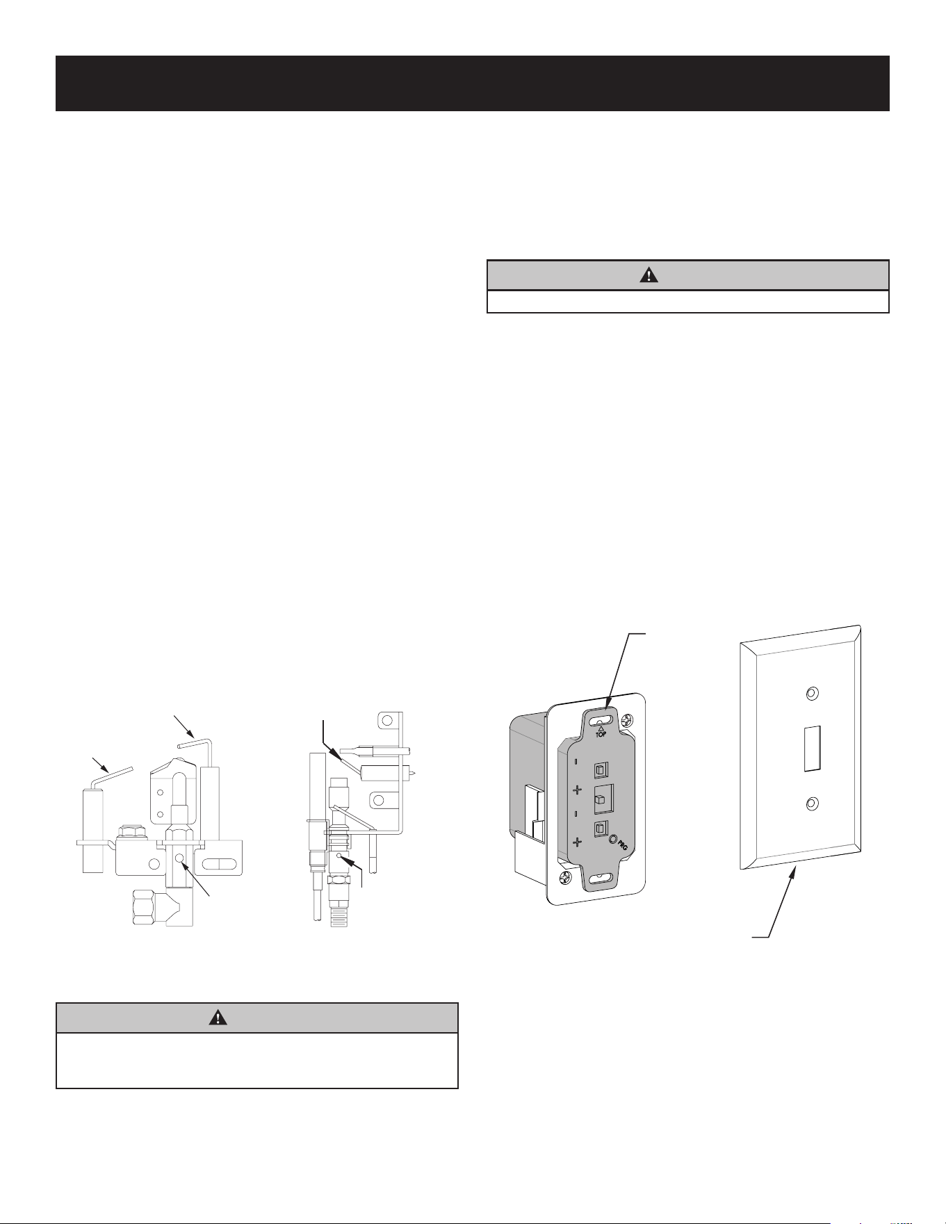
Page 50 46071-2-0725
Annual inspection and cleaning by the dealer or qualied service
technician is recommended to prevent malfunction.
TURN OFF FIREPLACE AND ALLOW TO COOL BEFORE
CLEANING.
Remove any optional decorative covers or decorative glass
material. Gloves are recommended.
PERIODIC CLEANING - Refer to parts diagram for location of
items discussed below.
• Do not use cleaning uid to clean any part of replace.
•
Clean glass with ammonia-free cleaner. Ammonia will etch or
stain glass when heated. (We recommend gas replace glass
cleaner.)
• Remove loose particles and dust from the burner, controls and
air shutter.
• Inspect and clean burner air intake hole. Remove lint or particles
with brush. Failure to keep air intake hole clean will result in
sooting and poor combustion.
ANNUAL CLEANING/INSPECTION - Refer to parts diagram for
location of items discussed below.
• Inspect and clean burner air intake hole. Remove lint or particles
with vacuum or brush. Failure to keep air intake hole clean will
result in sooting and poor combustion.
• Inspect and clean all burner ports.
• Inspect ODS pilot for operation and accumulation of lint at air
intake holes.
• Verify ame pattern for proper operation.
• Verify smooth and responsive ignition of main burner.
PILOT MAINTENANCE AND CLEANING
Oxygen Depletion Sensor Pilot
When the pilot has a large yellow tip ame, clean the Oxygen
Depletion Sensor as follows:
1.
Use canned air to blow through hole A. See Figures 86 and
87. This will blow out foreign materials such as dust, lint and
spider webs.
Intermittent Pilot Millivolt Pilot
Figure 86 Figure 87
WARNING
Never use needles, wires, or similar cylindrical objects to
clean the pilot to avoid damaging the calibrated ruby that
controls the gas ow.
2. If intermittent pilot replace stops working, clean ame sensor
B Figure 86 with a damp cloth.
3. If intermittent pilot ignitor does not spark, clean ignitor C
Figure 86 with a damp cloth.
CONTROL COMPARTMENT AND BURNER MAINTENANCE
Keep the control compartment and burner area clean by vacuuming
or brushing area at least twice a year.
WARNING
The replace can get very hot. Handle only when cool.
Always turn o gas to the pilot before cleaning. For relighting, refer
to lighting instructions located on the rating plate.
Never obstruct the ow of the combustion and ventilation air. Keep
the front of the replace clear of all obstacles.
BATTERY REPLACEMENT
An intermittent pilot may require more frequent battery changes.
To replace the batteries, follow these steps:
1. Remove the cover from the electrical box on the wall.
2. Replace the batteries inside the box.
3. Replace the cover using four (4) #4 x 1/2 Phillips screws.
To replace the batteries for a Millivolt model, follow these steps:
1. Remove the barrier screen assembly. See page 34.
2. Remove the optional glass media from inside the replace.
3. Lift and set aside the burner cover.
4. Lift the remote receiver.
5. Replace the four AA batteries.
6. Replace the items removed in steps 1 through 4.
Figure 88 - IP Remote Receiver
CLEANING AND SERVICING
C
B
A
C
A
c
A
REMOTE
SWITCH
COVER PLATE
REMOTE
SWITCH
COVER PLATE
46071-2-0725 Page 51
TROUBLESHOOTING
-
IP CONTROL SYSTEM
BRIEF DESCRIPTION OF THE COMPONENTS
The Digital Fireplace Control (DFC) is an automatic gas ignition
system based on a single micro-controller core. This control
manages all functions related to ignition, ame sensing and
supervision for atmospheric applications.
The DFC can be set to provide continuous or intermittent ignition
control sequences and ame monitoring with safety shutdown in
case of failure.
The DFC is set up as a standalone (AC powered system with
battery backup). See IP Lighting Instructions on page 35 and
Wiring Diagram on page 24.
TROUBLESHOOTING
Before proceeding with the procedures in the following
troubleshooting table, verify that the power supply (AC/DC
adapter) is present and that the batteries inside the remote switch
and remote control are fresh and installed with correct polarity.
Make sure all the connections between the wire harnesses and
system components are proper and positive.
Verify that the static inlet pressure meets the manufacturer’s
recommended inlet pressure. If necessary adjust the line pressure
regulator.
If the recommended actions for the following troubleshooting chart
do not help to address the problem consider replacing wiring
harnesses.
WARNING
Any actions performed on the gas valve must be performed
in accordance with this instruction manual. Likewise, any
actions performed on the DFC or other system components
must be done in accordance with the individual component
instructions. Replacement of components must be performed
in accordance with this instructions manual.
Page 52 46071-2-0725
TROUBLESHOOTING
-
IP CONTROL SYSTEM
(
CONT'D
)
PROBLEM OBSERVED POSSIBLE CAUSE CORRECTIVE MEASURE
Gas odor during setup Gas Leak
What To Do If You Smell Gas
Do not try to light any appliance.
Do not touch any electrical switch;
Do not use any phone in your building.
Immediately call your gas supplier from
a neighbor's phone. Follow the gas
supplier's instructions.
If you cannot reach your gas supplier,
call the re department.
Gas odor before rst ignition Gas Leak
Fireplace is on but no ame and pilot
is not trying to light
Gas Line Valve turned o Turn shut-o valve to open position.
Control module in lockout Turn power to replace o and then back on.
Pilot continues to spark when pilot is lit
Not enough gas to pilot Wait for pilot ame to strengthen.
Low Gas Pressure Check pressures. See page 20.
Pilot igniter/sensor is dirty
Clean pilot. See maintenance homeowner
manual.
Pilot not grounded well Check ground connections.
Draft in rebox Redirect draft from room or wall.
Pilot sensor has been bent Replace pilot.
Pilot will not ignite, or will not stay lit
Pilot igniter/sensor is dirty
Clean ame sensor and pilot igniter. See
maintenance homeowner manual.
Pilot not grounded well Check ground connections.
Sensor Wire loose Check sensor wire terminals.
Gas pressure incorrect Adjust gas pressure.
Pilot Gas Line bent or kinked Replace pilot tube.
Faulty pilot, Sensor bent Replace Pilot.
Faulty valve Replace Valve.
Burner takes too long to fully light
Low gas pressure Check gas supply pressure.
Clogged or dirty carryover/burner ports Clean ports.
Blocked orice Check orice opening.
Faulty valve Replace valve.
Burner does not light but pilot remains
on
Low gas pressure Check gas supply pressure.
Clogged or dirty burner ports Clean burner ports.
Blocked orice Check orice opening.
Loose wire connections Check valve/control module connections.
Faulty pilot Replace pilot.
Faulty valve Replace valve.
46071-2-0725 Page 53
Burner lights but does not stay lit while
pilot remains on
Low gas pressure Check gas supply pressure.
Loose sensor wire Check wire connection.
Faulty valve Replace valve.
Faulty pilot or thermocouple Replace Safety pilot.
Clogged or dirty burner ports Clean burner ports.
Room temperature is higher than
thermostat setting
Move remote away from replace.
Set higher temperature on remote/thermostat
Remote control batteries failing
Replace batteries in remote transmitter and
receiver.
Burner and pilot light but will not stay lit
Flame sensor dirty Clean pilot sensor.
Low gas pressure Check gas supply pressure.
Not enough fresh air for pilot Open door or window - ventilate.
Clogged or dirty burner ports Clean burner ports.
(For replace equipped with optional
thermostat or thermostat remote) Room
temperature is higher than thermostat
setting
Move (optional) remote away from replace.
Set higher temperature on (Optional) remote/
thermostat.
If using Propane Gas, verify pilot bracket is
not installed. Pilot bracket if included, will
be outside of burner box to the right and
above the pilot.
Remove pilot bracket.
Remote control batteries failing
Replace batteries in remote transmitter and
receiver.
Faulty pilot or thermocouple Replace pilot
Incorrect burner ame
Incorrect gas supply or pressure Check gas supply pressure.
Blocked orice Check orice opening.
Clogged or dirty burner ports Clean burner ports.
Faulty valve Replace valve.
High altitude Adjust orice size for altitude.
Backre of burner
Blocked orice Check orice opening.
Clogged or dirty burner ports Clean burner ports.
Low gas pressure Check gas supply pressure.
Fireplace produces unwanted odors
Vapors from paint, hairspray, glue, etc.
Ventilate room until odor stops. Do not use
paint, hairspray, glue, etc around replace.
Initial burn-o of manufacturing chemicals Ventilate room until odor stops.
Whistle noise from replace
Check gas pressure Adjust gas pressure to recommended setting.
Air in gas line Bleed lines.
Control knob not in fully open position Open control knob to full position.
Spiral gas ex line pinched or too small
diameter line
Straighten ex line where pinched or replace
gas feed line with larger diameter.
TROUBLESHOOTING
-
IP CONTROL SYSTEM
(
CONT'D
)
PROBLEM OBSERVED POSSIBLE CAUSE CORRECTIVE MEASURE
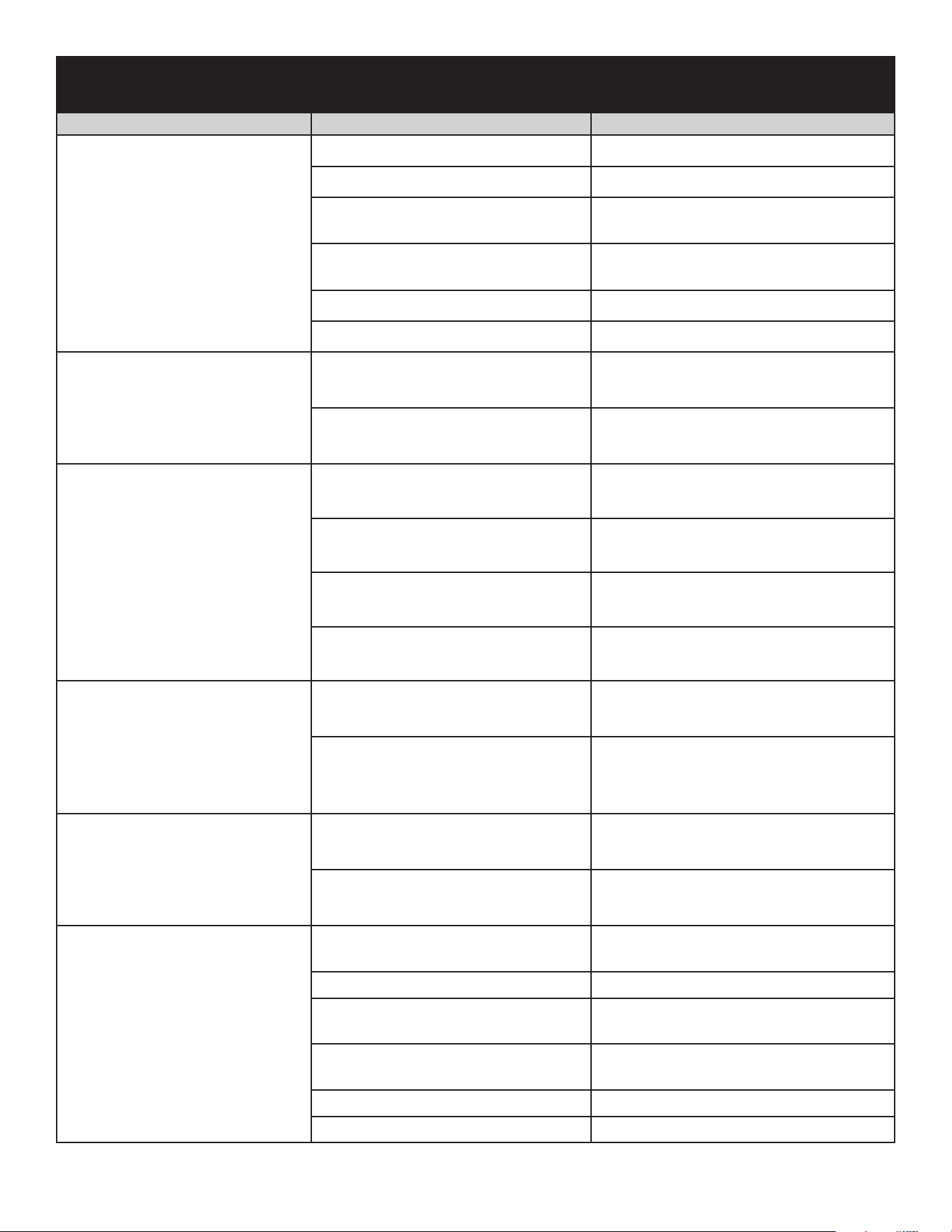
Page 54 46071-2-0725
PROBLEM OBSERVED POSSIBLE CAUSE CORRECTIVE MEASURE
When ignitor button is pressed, there is
no spark at ODS/pilot.
Ignitor electrode positioned wrong Replace pilot.
Ignitor electrode is broken Replace pilot.
Ignitor electrode not connected to ignitor
cable
Reconnect ignitor cable.
Ignitor cable pinched or wet. Keep ignitor
cable dry.
Free ignitor cable if pinched by any metal or tubing.
Broken ignitor cable Replace ignitor cable.
Bad piezo ignitor Replace piezo ignitor.
Fireplace produces unwanted odors
Fireplace burning vapors from paint, hair
spray, glues, etc.
Ventilate room. Stop using odor causing products
while replace is running.
Gas leak Locate and correct all leaks.
Fireplace shuts o during use. (Pilot and
main burner are o.)
Not enough fresh air is available for ODS
pilot to operate
Open window and/or door for ventilation.
Low Line Pressure Contact local gas company.
ODS/pilot is partially clogged Clean ODS/pilot.
Defective thermocouple Replace pilot.
Fireplace shuts o during use. (Pilot
stays on.)
Low line pressure Check line pressure to the valve.
Defective thermopile
Check pilot ame, check wire connections, output
should be a minimum of 325 millivolts across.
TH/TP and TP terminals with REMOTE/OFF/
ON switch o.
Gas odor even when control knob is in
OFF position
Gas leak Locate and correct all leaks.
Control valve defective Replace control valve.
When ignitor button is pressed, there
is spark at ODS/pilot, but no ignition
Gas supply turned o or manual shut-o
valve closed
Turn on gas supply or open manual shut-o valve.
Control knob not in PILOT position Turn control knob to PILOT position.
Control knob not pressed in while in PILOT
position
Press in control knob while in PILOT position.
Air in gas lines when installed
Continue holding down control knob. Repeat
igniting operation until air is removed.
ODS/pilot is clogged Replace ODS/pilot assembly or get it serviced.
Gas regulator setting is not correct Replace gas regulator.
TROUBLESHOOTING
-
MV CONTROL SYSTEM
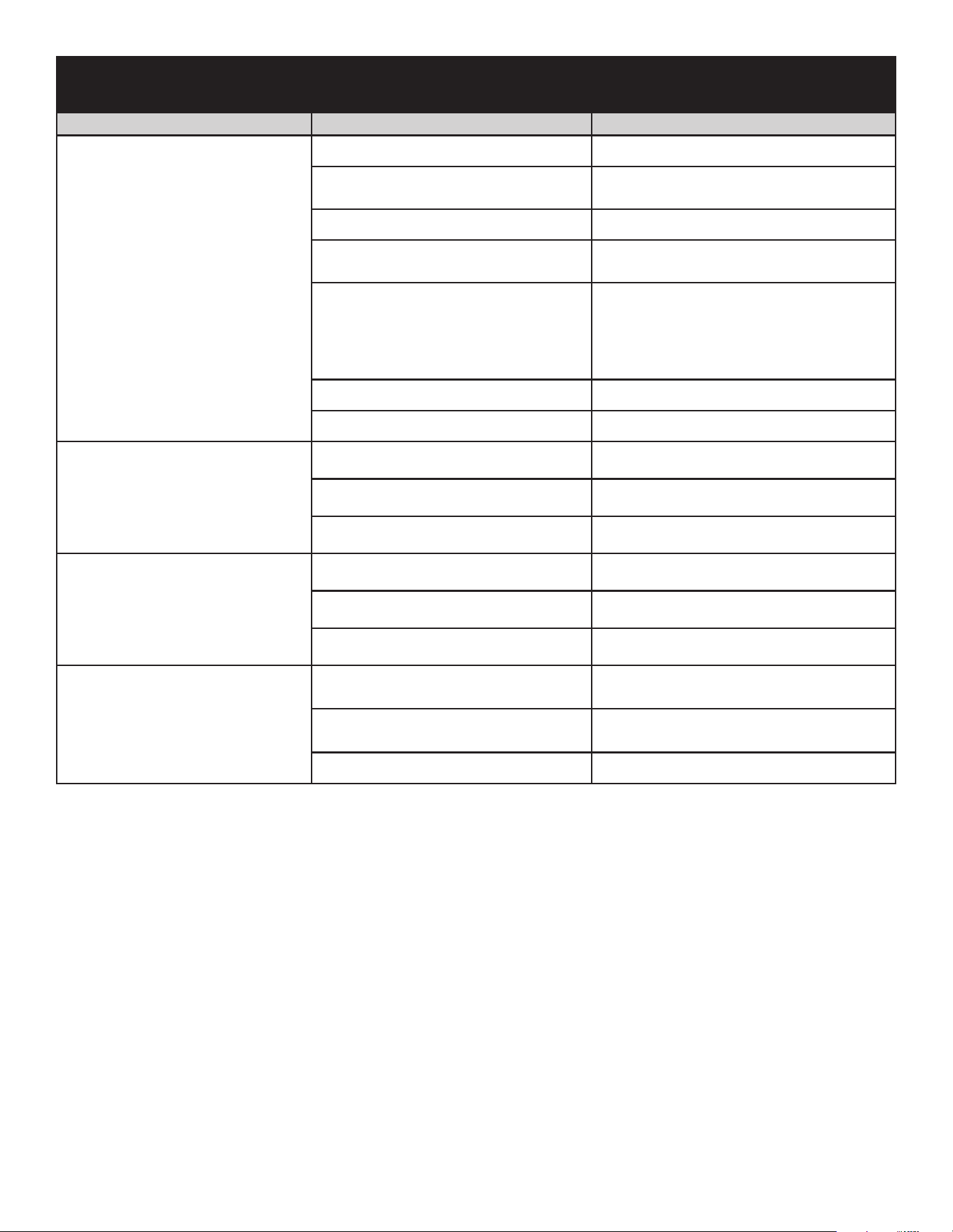
46071-2-0725 Page 55
ODS/pilot lights but ame goes out
when control knob is released
Control knob not fully pressed in Press in control knob fully.
Control knob not pressed in long enough
After ODS/pilot lights, keep control knob pressed
in 30 seconds.
Manual Shut-o valve not fully open Fully open manual shut-o valve.
Thermocouple connection loose at control
valve
Hand tighten until snug, then tighten 1/4 turn more.
Pilot flame not touching thermocouple,
which allows thermocouple to cool, causing
pilot ame to go out. This problem could be
caused by either low gas pressure or dirty
or partially clogged ODS/pilot.
Contact local gas company.
Thermocouple damaged Replace thermocouple.
Control valve damaged Replace control valve.
Burner does not light after ODS/pilot is lit
Burner orice clogged Clean burner or replace main burner orice.
Burner orice diameter is too small Replace burner orice.
Inlet gas pressure is too low Contact qualied service person.
If burning at main burner orice occurs
(a loud, roaring blow torch noise)
You must turn o burner assembly Contact a qualied service person.
Manifold pressure is too low Contact local gas company.
Burner orice clogged Clean burner or replace burner orice.
Fireplace produces a whistling noise when
main burner is lit
Turning control knob to HIGH position when
main burner is cold
Turn control knob to LOW position and let warm
up for a minute.
Air in gas line
Operate burner until air is removed from line.
Have gas line checked by local gas company.
Dirty or partially clogged burner orice Clean burner or replace burner orice.
If the gas quality is bad, the pilot may not stay lit, the burners may produce soot and the replace may backre when lit. If the gas quality
or pressure is low, contact the local gas supplier immediately.
PROBLEM OBSERVED POSSIBLE CAUSE CORRECTIVE MEASURE
TROUBLESHOOTING
-
MV CONTROL SYSTEM
(
CONT’D
)
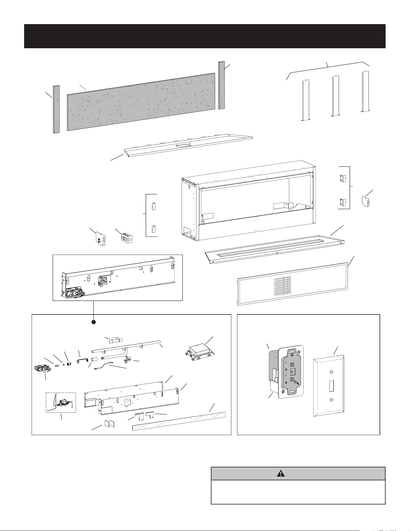
Page 56 46071-2-0725
VFLB(36,48)FP90
-
EXPLODED VIEW
WARNING
Failure to position the parts in accordance with these diagrams
or failure to use only parts specically approved with this
heater may result in property damage or personal injury.
5
10
9
BURNER ASSEMBLY- IP
WALL PANEL ASSEMBLY
2
3
12
13
11
19
21
24
14
25
17
16
20
18
22
23
X4
5
3
6
1
X3
4
15
X2
7
8
26
27
28
29
30
18
7

46071-2-0725 Page 57
VFLB(36,48)FP90
-
PARTS LIST
N/S B100100 B100100 Fitting - 3/8 Flare to 3/8 Pipe
N/S R7591 R7591 Flex Line
N/S R11128 R11128 Power Adaptor, 7.0 VDC
N/S R11123 R11123 Control Module Harness
N/S R11237 R11237 Receiver Harness
N/S R11973 R11973 Receiver Harness Extension
N/S R11236 R11236 Remote
N/S R11332 R11332 Flame Sensor Wire
N/S R11333 R11333 Ignitor Wire
N/S R3492 R3492 Receptacle
N/S R3491 R3491 Junction Box Cover
*A Also requires R11597 and R11598.
*B Also requires R1978.
*C Included with R11235.
*D Wall box not supplied.
INDEX
NO.
PART NO.
DESCRIPTION
VFLB36FP VFLB48FP
1 36787 36787
Stando Bracket (3 Required)
2 40223 40224
Non-Combustible Board - Top
3 40222 40222
Non-Combustible Board -
Side (2 Required)
4 44289 44304 Inner Firebox Top Assembly
5 42261 42261 Nailing Flange (4 Required)
6 R3490 R3490 Junction Box
7 40187 40187 Junction Box Access Plate
9 40114 40115 Burner Cover Assembly
10 40309 40310 Barrier Screen Assembly
11 N/A N/A Wall Plate *C
12 R11235 R11235 Remote Receiver
13 N/A N/A Wall Plate *D
14 R12695 R11747 Glass - Burner
15 R12432 R12432
Glass Side Burner (2 Required)
16 46109 46111 Burner Box - Front
17 40104 40105 Burner Box - Back
18 40113 40113
Pilot Tube Assembly
(Propane Only) *A*B
18 44428 44428
Regulator Replacement Kit
(NAT, IP)
19 R11234 R11234 Valve - Propane
19 R11233 R11233 Valve - Natural
20 P313 P313 Fitting - Orice Holder
21 P258 P250 Orice - Propane
21 P257 P243 Orice - Natural
22 R7624 R7624 Air Shutter
23 34440 34440 Pilot Bracket
24
R11327
2019
R11327
2019
Pilot - Propane
24
R11328
2019
R11328
2019
Pilot - Natural
25 R12664 R12665 Burner Tube Assembly
26 37482 37482 Pilot Shield (Natural Only)
27 R12907 R12907 Control Module - Proame
28 31234 NONE
Venturi Target (36 Natural Only)
29 P251 NONE Coupling (36 Natural Only)
30 40110 40110 Pilot Shield (Propane Only)
N/S R11597 R11597 Tubing Ferrule - Pilot N/S
N/S R11598 R11598 Tubing Nut - Pilot
N/S R1978 R1978 Tubing Nut & Ferrule - Valve
INDEX
NO.
PART NO.
DESCRIPTION
VFLB36FP VFLB48FP
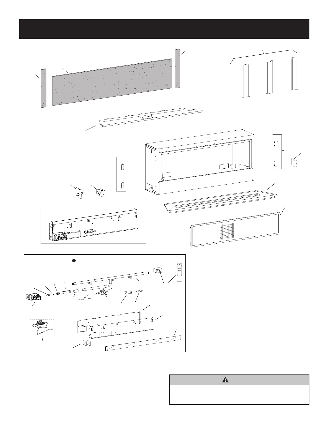
Page 58 46071-2-0725
VFLB(36,48)FP30
-
EXPLODED VIEW
WARNING
Failure to position the parts in accordance with these diagrams
or failure to use only parts specically approved with this
heater may result in property damage or personal injury.
5
10
9
BURNER ASSEMBLY- MV
2
3
19
21
24
14
25
17
16
20
18
22
X4
5
3
6
1
X3
4
15
X2
7
8
12
11
13
23
26
18
7

46071-2-0725 Page 59
VFLB(36,48)FP30
-
PARTS LIST
N/S R3492 R3492 Receptacle
N/S R3491 R3491 Junction Box Cover
*A Also requires R1978.
INDEX
NO.
PART NO.
DESCRIPTION
VFLB36FP VFLB48FP
1 36787 36787
Stando Bracket (6 Required)
2 40223 40224
Non-Combustible Board - Top
3 40222 40222
Non-Combustible Board -
Side (2 Required)
4 44289 44304 Inner Firebox Top Assembly
5 42261 42261 Nailing Flange (4 Required)
6 R3490 R3490 Junction Box
7 40187 40187 Junction Box Access Plate
9 40114 40115 Burner Cover Assembly
10 40309 40310 Barrier Screen Assembly
11 26304 26304 Ignitor Bracket
12 FRBC FRBC Transmitter And Receiver
13 R9760 R9760 Piezo Ignitor
14 R12695 R11747 Glass - Burner
15 R12432 R12432
Glass Side Burner (2 Required)
16 46108 46110 Burner Box - Front
17 40104 40105 Burner Box - Back
18 40388 40388
Pilot Tube Assembly
(Propane Only) *A
18 44426 44426
Regulator Replacement Kit
(NAT, MV)
19 R3625 R3625 Valve - Propane
19 R3626 R3626 Valve - Natural
20 P313 P313 Fitting - Orice Holder
21 P258 P250 Orice - Propane
21 P257 P243 Orice - Natural
22 R7624 R7624 Air Shutter
23 31234 NONE
Venturi Target (36 Natural Only)
24 R3623 R3623 Pilot - Propane
24 R3624 R3624 Pilot - Natural
25 R12664 R12665 Burner Tube Assembly
26 P251 P251 Coupling (36 Natural Only)
N/S R1978 R1978 Tubing Nut & Ferrule - Valve
N/S B100100 B100100 Fitting - 3/8 Flare to 3/8 Pipe
N/S R7591 R7591 Flex Line
N/S R5668 R5668 Ignitor Wire
INDEX
NO.
PART NO.
DESCRIPTION
VFLB36FP VFLB48FP
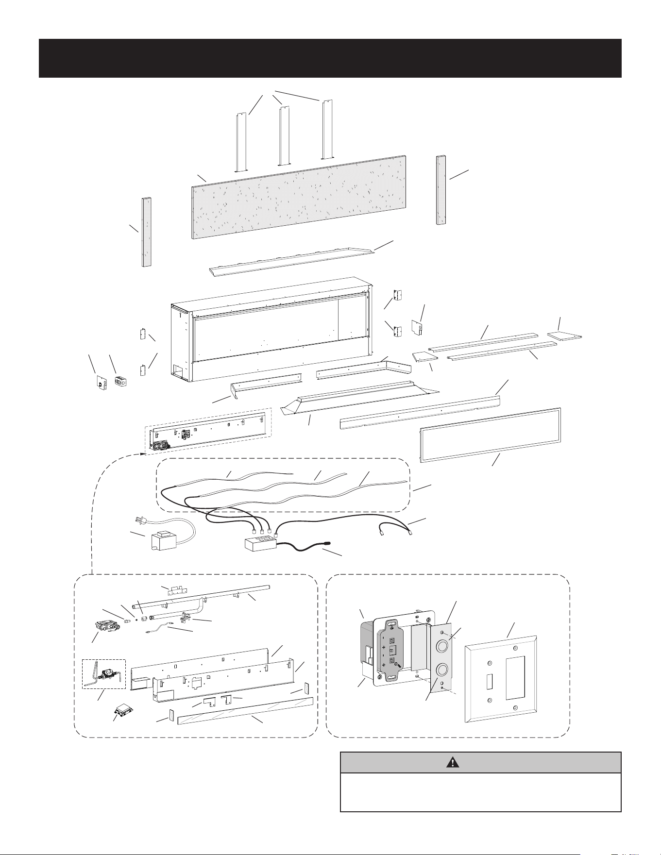
Page 60 46071-2-0725
WARNING
Failure to position the parts in accordance with these diagrams
or failure to use only parts specically approved with this
heater may result in property damage or personal injury.
9
VFLB(60,72)FP90
-
EXPLODED VIEW
WARNING
Failure to position the parts in accordance with these diagrams
or failure to use only parts specically approved with this
heater may result in property damage or personal injury.
5
5
8
13
12
11
7
1
30
32
35
25
36
28
27
31
29
33
BURNER ASSEMBLY
34
WALL PANEL ASSEMBLY
22
24
23
21
23
4
6
2
3
3
18
19
15
14
20
17
16
39
37
10
9
41
42
40
42
26
26
38
29
45
9

46071-2-0725 Page 61
VFLB(60,72)FP90
-
PARTS LIST
32 P211 P211 Orice - Natural
33 R7624 R7624 Air Shutter
34 34440 34440 Pilot Bracket
35
R11327
2019
R11327
2019
Pilot - Propane
35
R11328
2019
R11328
2019
Pilot - Natural
36 R12666 R12667 Burner Tube Assembly
37 37482 37482 Pilot Shield (Natural Only)
37 N/A 37482 Pilot Shield (Propane Only)
38 40110 N/A Pilot Shield (Propane Only)
39 36876 37344
LED Replacement Kit
(Includes #16,17,18)
40 36784 36812 Glass Support Right
41 36785 36813 Glass Support Left
42 36786 36814
Glass Support Center
(2 Required)
45 R12907 R12907 Control Module - Proame
N/S R11597 R11597 Tubing Ferrule - Pilot N/S
N/S R11598 R11598 Tubing Nut - Pilot
N/S R1978 R1978 Tubing Nut & Ferrule - Valve
N/S B100100 B100100 Fitting - 3/8 Flare to 3/8 Pipe
N/S R7591 R7591 Flex Line
N/S R11128 R11128 Power Adaptor, 7.0 VDC
N/S R11123 R11123 Control Module Harness
N/S R11237 R11237 Receiver Harness
N/S R11973 R11973 Receiver Harness Extension
N/S R11236 R11236 Remote
N/S R11332 R11332 Flame Sensor Wire
N/S R11333 R11333 Ignitor Wire
N/S R3492 R3492 Receptacle (2 Required)
N/S R3491 R3491 Junction Box Cover
*A Also requires R11597 and R11598.
*B Also requires R1978.
INDEX
NO.
PART NO.
DESCRIPTION
VFLB60FP VFLB72FP
1 36787 36787
Stando Bracket (3 Required)
2 40225 40226
Non-Combustible Board - Top
3 40222 40222
Non-Combustible Board -
Side (2 Required)
4 44324 44336 Inner Firebox Top
5 42261 42261 Nailing Flange (4 Required)
6 40202 40203 Reector Rear - Right
7 40204 40205 Reector Rear - Left
8 R3490 R3490 Junction Box
9 40187 40187 Junction Box Access Plate
11 40189 40190
Reective Burner Cover
Assembly
12 40195 40197 Reector Front Assembly
13 40311 40312 Barrier Screen Assembly
14 R12294 R12294 Wire Harness - Switches
15 R13283 R13283 Control Module - LED
16 R11918 R11986 LED Lighting Strip - Front
17 R11918 R11918
LED Lighting Strip -
Rear Right
18 R11918 R11986
LED Lighting Strip -
Rear Left
19 R11920 R11920 Transformer - LED
20 43687 43687 Bracket - LED Buttons
21 R12296 R12296 Wall Plate
22 R11235 R11235 Remote Receiver
23 R11921 R11921
Switch Button - LED
(2 Required)
24 R12295 R12295 Wall Box
25 R12292 R12293 Glass - Burner
26 R12432 R12432
Glass - Side Burner
(2 Required)
27 46112 46113 Burner Box - Front
28 40107 40109 Burner Box - Back
29 40113 40113
Pilot Tube Assembly
(Propane Only) *A*B
29 44428 44428
Regulator Replacement Kit
(NAT, IP)
30 R11234 R11234 Valve - Propane
30 R11233 R11233 Valve - Natural
31 P313 P313 Fitting - Orice Holder
32 P304 P304 Orice - Propane
INDEX
NO.
PART NO.
DESCRIPTION
VFLB60FP VFLB72FP

Page 62 46071-2-0725
To Order Parts Under Warranty, please contact your local Empire dealer. See the dealer locator at www.empirecomfort.
com. To provide warranty service, your dealer will need your name and address, purchase date and serial number, and
the nature of the problem with the unit.
To Order Parts After the Warranty Period, please contact your dealer or one of the Master Parts Distributors listed below.
This list changes from time to time. For the current list, please click on the Master Parts button at www.empirecomfort.com
.
Please note: Master Parts Distributors are independent businesses that stock the most commonly ordered Original
Equipment repair parts for Heaters, Grills, and Fireplaces manufactured by Empire Comfort Systems Inc.
MASTER PARTS DISTRIBUTOR LIST
Parts Not Under Warranty
Parts can be ordered through your Service Person, Dealer, or a Master Parts Distributor. See this page for the Master Parts Distributors
list. For best results, the service person or dealer should order parts through the distributor. Parts can be shipped directly to the
service person/dealer.
Warranty Parts
Warranty parts will need a proof of purchase and can be ordered by your Service Person or Dealer. Proof of purchase is required for
warranty parts.
All parts listed in the Parts List have a Part Number. When ordering parts, rst obtain the Model Number and Serial Number from the
name plate on your equipment. Then determine the Part Number (not the Index Number) and the Description of each part from the
following illustration and part list. Be sure to give all this information . . .
Fireplace Model Number Part Description
Fireplace Serial Number Part Number
Type of Gas (Propane or Natural)
Do not order bolts, screws, washers or nuts. They are standard hardware items and can be purchased at any local hardware store.
Shipments contingent upon strikes, res and all causes beyond our control.
HOW TO ORDER REPAIR PARTS
Dey Distributing
1401 Willow Lake Boulevard
Vadnais Heights, MN 55101
Phone: 651-490-9191
Toll Free: 800-397-1339
Website: www.deydistributing.com
Parts: Heater, Hearth and Grills
F. W. Webb Company
200 Locust Street
Hartford, CT 06114
Phone: 860-722-2433
Toll Free: 800-243-9360
Fax: 860-293-0479
Toll Free Fax: 800-274-2004
Website: www.fwwebb.com
Parts: Heater, Hearth and Grills
East Coast Energy Products
10 East Route 36
West Long Branch, NJ 07764
Phone: 732-870-8809
Toll Free: 800-755-8809
Fax: 732-870-8811
Website: www.eastcoastenergy.com
Parts: Heater, Hearth and Grills

46071-2-0725 Page 63
WARRANTY
Empire Comfort Systems Inc. warranties this hearth product to be free from defects at the time of purchase and for the periods specied
below. Hearth products must be installed by a qualied technician and must be maintained and operated safely, in accordance with the
instructions in the owner’s manual. This warranty applies to the original purchaser only and is not transferable. All warranty repairs must
be accomplished by a qualied gas appliance technician.
Limited Lifetime Parts Warranty with a Five-Year Limited Labor Warranty – Combustion Chamber and Heat Exchanger
If the combustion chamber or heat exchanger (see parts list) fails because of defective workmanship or material, Empire will
repair or replace at Empire’s option. Within ve years from the date of purchase, Empire will pay reasonable labor to have the
defective part repaired or replaced at Empire’s option.
Limited Five-Year Parts & Labor Warranty – All Other Components
(Except Remote Controls, Thermostats, Accessories and Replacement Parts)
Should any part fail because of defective workmanship or material within ve years from the date of purchase, Empire will repair
or replace at Empire’s option. Within ve years from the date of purchase, Empire will pay reasonable labor to have that defect
repaired at Empire’s option.
Limited One-Year Parts Warranty – Remote Controls, Thermostats, Accessories, and Parts
Should any remote control, thermostat, accessory, or other part fail because of defective workmanship within one year from the
date of purchase, Empire will repair or replace at Empire’s option.
Duties Of The Owner
The appliance must be installed by a qualied installer and operated in accordance with the instructions furnished with the
appliance. A bill of sale, cancelled check, or payment record should be kept to verify purchase date and establish warranty
period. Ready access to the appliance for service.
What Is Not Covered
Damages that might result from the use, misuse, or improper installation of this appliance.
Travel, diagnostic costs and freight charges on warranted parts to and from the factory.
Claims that do not involve defective workmanship or materials.
Unauthorized service or parts replacements.
Removal and reinstallation cost.
Inoperable due to improper or lack of maintenance.
How To Get Service
To make a claim under this warranty, please have your receipt available and contact your installing dealer. Provide the dealer
with the model number, serial number, type of gas, and purchase verication. The installing dealer is responsible for providing
service and will contact the factory to initiate any warranted parts replacements. Empire will make replacement parts available
at the factory. Shipping expenses are not covered.
If, after contacting your Empire dealer, service received has not been satisfactory, contact: Consumer Relations Department,
Empire Comfort Systems Inc., PO Box 529, Belleville, Illinois 62222, or send an e-mail to [email protected] with
“Consumer Relations” in the subject line.
Your Rights Under State Law
This warranty gives your specic legal rights, and you may also have other rights, which vary from state to state.

Page 64 46071-2-0725
www.empirecomfort.com
Empire Comfort Systems Inc.
Belleville, IL
If you have a general question
about our products, please e-mail
us at [email protected].
If you have a service or repair
question, please contact your dealer.