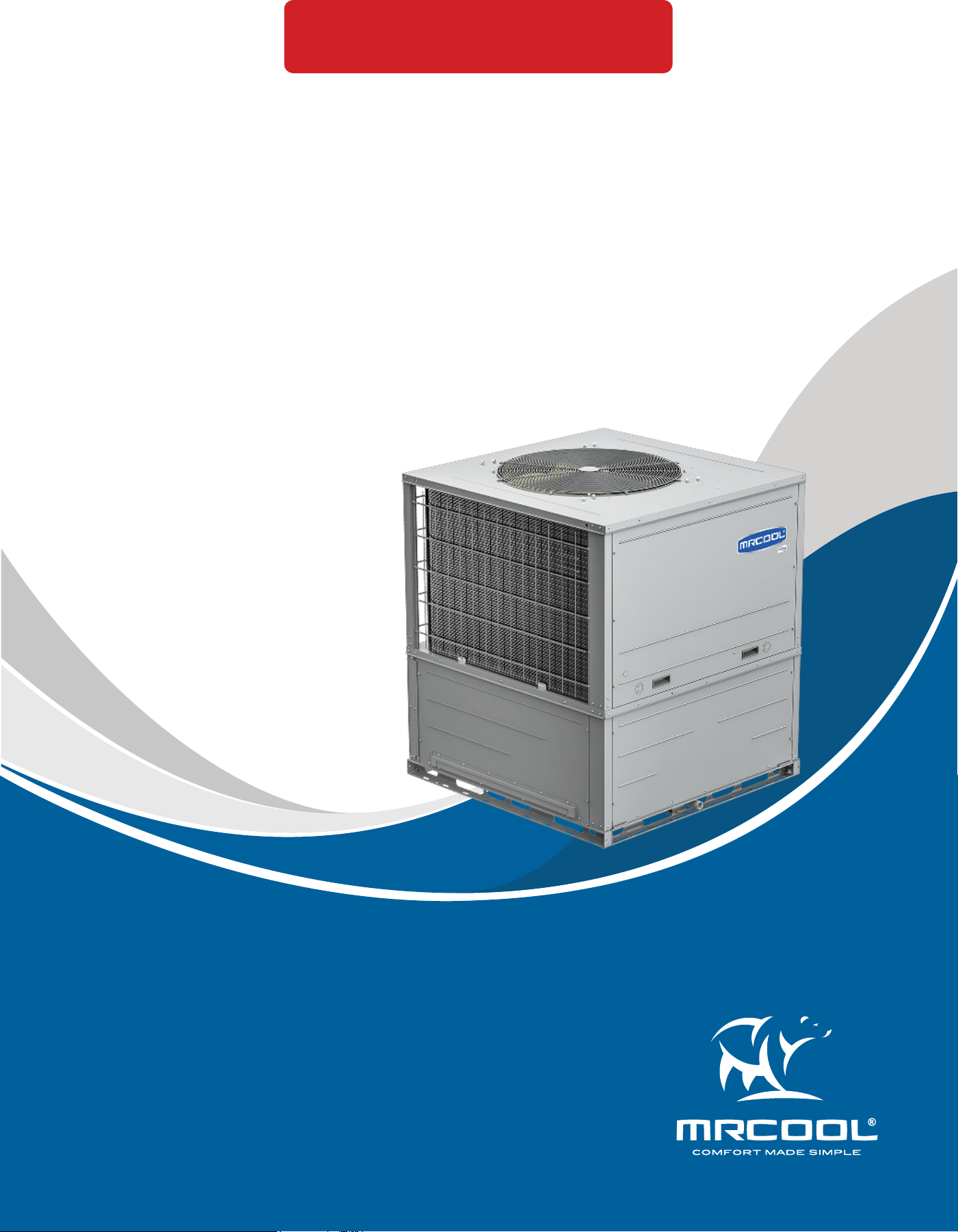
Universal
®
Series
DC Inverter
Package Unit
Installation &
Owner’s Manual
MODELS:
MDPH180*D
Read this manual carefully before installation and keep it where the
operator can easily nd it for future reference.
Due to updates and constantly improving performance, the
information and instructions within this manual are subject to
change without notice.
Version Date: September 10, 2025
Please visit www.mrcool.com/documentation
to ensure you have the latest version of this manual.
This product utilizes R-32 refrigerant

mrcool.com1
CONTENTS
SAFETY ................................................................................................................... 2
UNIT OVERVIEW & FEATURES.............................................................................. 5
2.1 Unit Information & Features .................................................................. 5
2.2 Operating Range ..................................................................................... 5
2.3 Codes & Regulations ............................................................................... 5
2.4 Physical Dimensions ............................................................................... 5
2.5 Main Parts ................................................................................................ 6
PRE-INSTALLATION .............................................................................................. 7
3.1ProductVerication&ReplacementParts ........................................... 7
3.2 Location Selection Requirements .......................................................... 7
3.3 Installation Location Dimensions & Clearances .................................. 8
3.4 Minimum Room Area .............................................................................. 8
3.5MinimumCirculationAirow ................................................................. 9
3.6 Refrigerant Sensor ................................................................................... 9
UNIT INSTALLATION .......................................................................................... 10
4.1 Curb-Mounted Installation ................................................................... 10
4.2 Pad-Mounted Installation ..................................................................... 10
4.3 Rigging & Lifting .................................................................................... 11
4.4 Horizontal Duct & Vertical Duct Conversion ...................................... 11
4.5 Installation of Condensation Pipe ....................................................... 12
4.6 Dip Switch Instruction .......................................................................... 13
4.7 Fan Performance Data .......................................................................... 13
DUCTWORK ......................................................................................................... 14
ELECTRIC HEATER ............................................................................................... 15
6.1 Electric Heater Safety ............................................................................ 15
6.2 Compatible Heat Kits ............................................................................. 15
6.3 Heat Kit Installation Precautions ......................................................... 15
6.4 Heat Kit Installation Steps ................................................................... 15
ELECTRICAL INSTALLATION .............................................................................. 16
7.1 Electrical Parameters ............................................................................ 16
7.2 Terminal Connection ............................................................................. 17
7.3 Wiring Diagram ...................................................................................... 18
7.4 Engineering Wiring Diagram ................................................................ 19
TRIAL RUN & TROUBLESHOOTING ................................................................... 20
8.1 Post-Installation Check ......................................................................... 20
8.2 Trial Run ................................................................................................. 20
8.3 Troubleshooting .................................................................................... 21
MAINTENANCE ................................................................................................... 25
9.1 Cleaning the Air Filter ........................................................................... 25
9.2 Drainage Pipe ........................................................................................ 25
9.3 Cleaning the Heat Exchanger .............................................................. 25
9.4 Before Seasonal Use ............................................................................. 25
9.5 After Seasonal Use ................................................................................ 26
9.6 Parts Replacement ................................................................................ 26
2
Contents
1
3
4
5
6
7
8
9
mrcool.com 2 2
SAFETY
1
This marking indicates that this product should not be disposed with other household wastes
throughout the North America. To prevent possible harm to the environment or human health from
uncontrolled waste disposal, recycle it responsibly to promote the sustainable reuse of material
resources. To return your used device, please use the return and collection systems or contact the
retailer where the product was purchased. They can take this product for environmental safe recycling.
9.7 After-Sale Service .................................................................................. 26
9.8 Unventilated Areas ............................................................................... 26
9.9 Transportation & Marking ................................................................... 26
9.10 Servicing ............................................................................................... 27
Incorrect usage may cause serious damage or injury.
The symbols below are used throughout this manual to indicate instructions that should be followed closely or
actions that should be avoided to prevent death, injury, and/or property damage.
Safety Precautions
Read Before Using
CAUTION
Indicates that ignoring instructions may cause death or serious injury.
Indicates that ignoring instructions may cause bodily injury, damage to
the unit, or other surrounding property.
Indicates that you should NEVER perform the indicated action.
WARNING
PROHIBITED
1. The air conditioner should be grounded to avoid electric shock. Do not connect the ground wire to gas
pipe, water pipe, lightning arrester or telephone wire.
2. The unit should be stored in a well-ventilated area where the room size corresponds to the correct
specied room area.
3. The unit should be stored in a room without continuously operating open ames (for example: an
operating gas appliance) and ignition sources (for example: an operating electric heater).
4. According to federal/state/local laws and regulations, all packages and transportation materials, including
nails, metal or wooden parts, and plastic packing material must be treated in a safe way.
5. The unit should be at least 5ft (1.5m) away from any inammable surface.
6. The range of external static pressures at which the unit was tested measures 0-0.8 inches W.C. (those with
add-on heat pumps and ducted units with supplementary heaters only).
7. Do not use means to accelerate the defrosting process or to clean, other than those recommended by
MRCOOL®.
8. The unit should be stored in a room without continuously operating ignition sources (for example: open
ames, an operating gas appliance, or an operating electric heater.
9. Do not pierce or burn.
10. Be aware that refrigerants may not contain an odor.
11. Electric heating and the unit need to be 5ft (1.5m) away from other ammable materials or 1ft (0.3m) away
from the wall.
12. The material of the plenum and ductwork must meet the standard NFPA 90B. The supply air plenum
or duct must have a solid sheet metal bottom piece directly after the unit with no openings, registers,
or exible air ducts located in it. The rst 6in (15.24cm) of supply air plenum and ductwork must be
constructed of sheet metal as required by NFPA 90B. The metal plenum of duct may be connected to the
non-combustible oor base for downow. Exposing combustible non-metal material to the supply opening
of a downow unit can cause a re resulting in property damage, personal injury, or death. If exible
supply air ducts are used, they may be located only in the side walls of the rectangular plenum, a minimum
of 6in (15.24cm) from the bottom.
13. All phases of this installation must conform to national, state, and local codes. If additional information is
required, please contact your dealer or MRCOOL® Technical Department at (270) 366-0457 or at support@
mrcool.com.
mrcool.com3
SAFETY
1
WARNING
1. Please install the unit according to this instruction manual. Installation must be performed in accordance
with the requirement of NEC and CEC by authorized personnel only.
2. Any person who is involved with working on or breaking into a refrigerant circuit should hold a current
valid certicate from an industry-accredited assessment authority, which authorizes their competence to
handle refrigerants safely in accordance with an industry recognized assessment specication.
3. Servicing shall only be performed as recommended by MRCOOL®.
4. The appliance shall be installed in accordance with national wiring regulations.
5. The xed wires connecting to the appliance must be congured with all-pole disconnection device under
voltage grade III according to wiring rules.
6. Air conditioner should be stored with protective measures against mechanical damage caused by accident.
7. During installation, use the specialized accessories and components, otherwise water leakage, electric
shock, or re hazard may occur.
8. Please install the air conditioner in a secure place that can withstand the weight of the air conditioner.
Insecure installation may cause the air conditioner to fall down, leading to injury.
9. An independent power circuit must be utilized. If the power cord is damaged, it must be repaired by
MRCOOL®, service agent, or other professional agents.
10. The unit can be cleaned only when it’s turned o and the power is disconnected, otherwise electric shock
may occur.
11. The air conditioner is not intended to be cleaned or maintained by children without supervision.
12. Do not alter the setting of the pressure sensor or other protective devices. If the protective devices are
short-circuited or changed against the rules, re hazard or even explosion may occur.
13. Do not operate the air conditioner with wet hands. Do not wash or sprinkle water on the air conditioner,
otherwise malfunction or electric shock will occur.
14. Do not dry the lter with naked ame or an air blower; otherwise the lter will be out of shape.
15. If the unit is to be installed in a small space, adopt protective measures to prevent the concentration of
refrigerant from exceeding the allowable safety limit; excessive refrigerant leakage may lead to explosion.
16. This appliance is not intended for use by persons (including children) with reduced physical, sensory, or
mental capabilities, or those lacking experience and knowledge, unless they have been given supervision
or instruction concerning use of the appliance by a person responsible for their safety. Children should be
supervised to ensure that they do not play with the appliance.
17. The unit must be permanently grounded. Failure to do so can lead to electrical shock causing personal
injury or death.
CAUTION
1. Do not put a nger or other objects into the air inlet or return air grill.
2. Adopt safety protection measures before touching the refrigerant pipe; otherwise injury may occur.
3. Please arrange the drain pipe according to the instruction manual.
4. Never stop the air conditioner by directly cutting o the power.
5. Never install the air conditioner in the following places:
A. Places with oil, smoke or volatile liquid: plastic parts may deteriorate and fall o or cause water
leakage.
B. Places with corrosive gas, copper pipe, or welding parts may be corroded and cause refrigerant
leakage.
6. Use measures to protect the unit from small animals, as they may damage electrical components and
cause malfunction of the air conditioner.
7. This product can’t be installed in corrosive, ammable, or explosive environments to prevent re or injury.
8. Improper installation, adjustment, alteration, service, maintenance, or use can cause explosion,
re, electrical shock, or other conditions, which may cause death, personal injury, or property
damage. Consult a qualied installer, service agency, or your distributor for information or
assistance.
9. The qualied installer or agency must use factory-authorized kits or accessories when modifying this
product. Refer to the individual instructions packaged with the kits or accessories when installing.
10. Follow all safety codes. Wear safety glasses, protective clothing, and work gloves. Use quenching cloth for
brazing operations. Have re extinguisher available.
mrcool.com 4
4
NOTE
1. If a thermostat is to be used, it should be connected rst before powering up the unit, otherwise the
thermostat may not work properly.
2. Only use a soft, dry cloth or slightly wet cloth with neutral detergent to clean the casing of the unit.
3. Before operating the unit under low temperature, connect it to power for 8 hours. If it is stopped for a
short time, for example, one night, do not cut o the power (This is to protect the compressor).
4. In order to ensure the reliability of the compressor, the unit forces the compressor to run for at least 6
minutes every time the compressor turns on, regardless of room temperature. Therefore, it is necessary,
for the sake of the compressor, the thermostat completes its minimum run time or that you delay turning
the indoor unit o for a few minutes after the outdoor unit shuts down or stops after reaching the
appropriate temperature. This is to avoid the indoor unit being turned o by the thermostat while the
outdoor unit is still running, which can result in equipment malfunction.
NOTE
1. In order to ensure reliability of product, the product may consume some power under “standby status” for
maintaining normal communication of the system, preheating refrigerant, and lubricant. If the product is
not to be used for long, cut o the power supply; please energize and preheat the unit in advance before
reusing it.
2. If the product needs to be installed, moved, or maintained, please contact your designated dealer or local
service center for professional support. Users should not disassemble or maintain the unit by themselves,
otherwise it may cause relative damage, and MRCOOL® will bear no responsibility.
3. All the illustrations and information in the instruction manual are for reference only. In order to make the
product better, we will continuously conduct improvements and innovations. If there are modications to
the product, refer to our online documentation for the most recent version of this manual.
4. Consult local building codes and National Electrical Code (NEC) for special requirements.
5. Read these instructions thoroughly and follow all warnings or cautions included in literature and attached
to the unit.
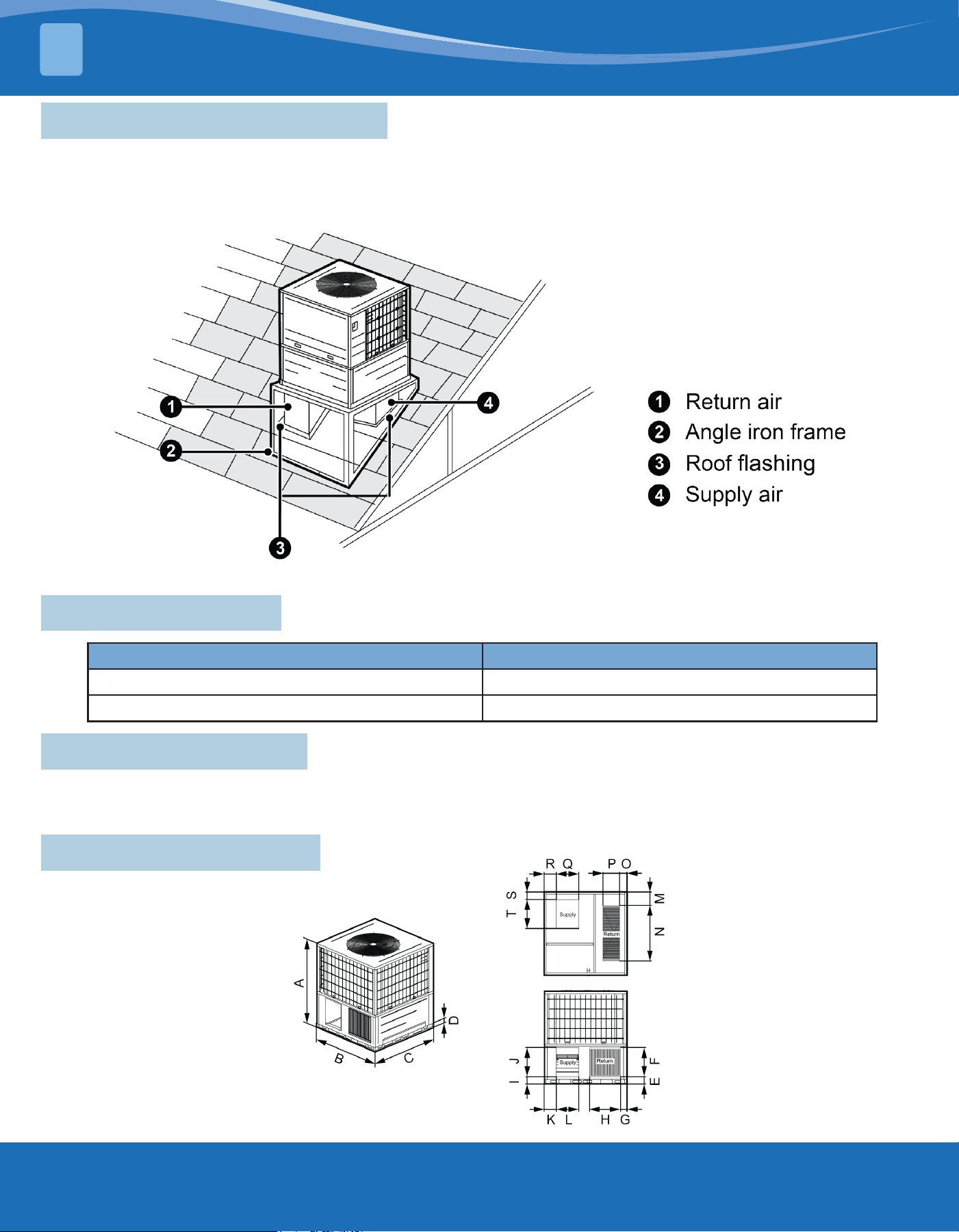
Symbols Displayed on Unit
WARNING The appliance is lled with ammable R32 refrigerant
CAUTION Before use, read the manual.
CAUTION Before repair, read the manual.
CAUTION Before installation, read the manual.
SAFETY
1
mrcool.com5
UNIT OVERVIEW & FEATURES
2
2.1 Unit Information & Features
The unit is completely assembled, piped, and wired at the factory to provide one-piece shipment and rigging. Each
unit is pressurized with a holding charge of R-32 for storage and shipping.
The compact design, attractive appearance, outstanding anti-rust cabinet, and quiet operation make these units
suitable for homes, oces, restaurants, residences, or similar places.
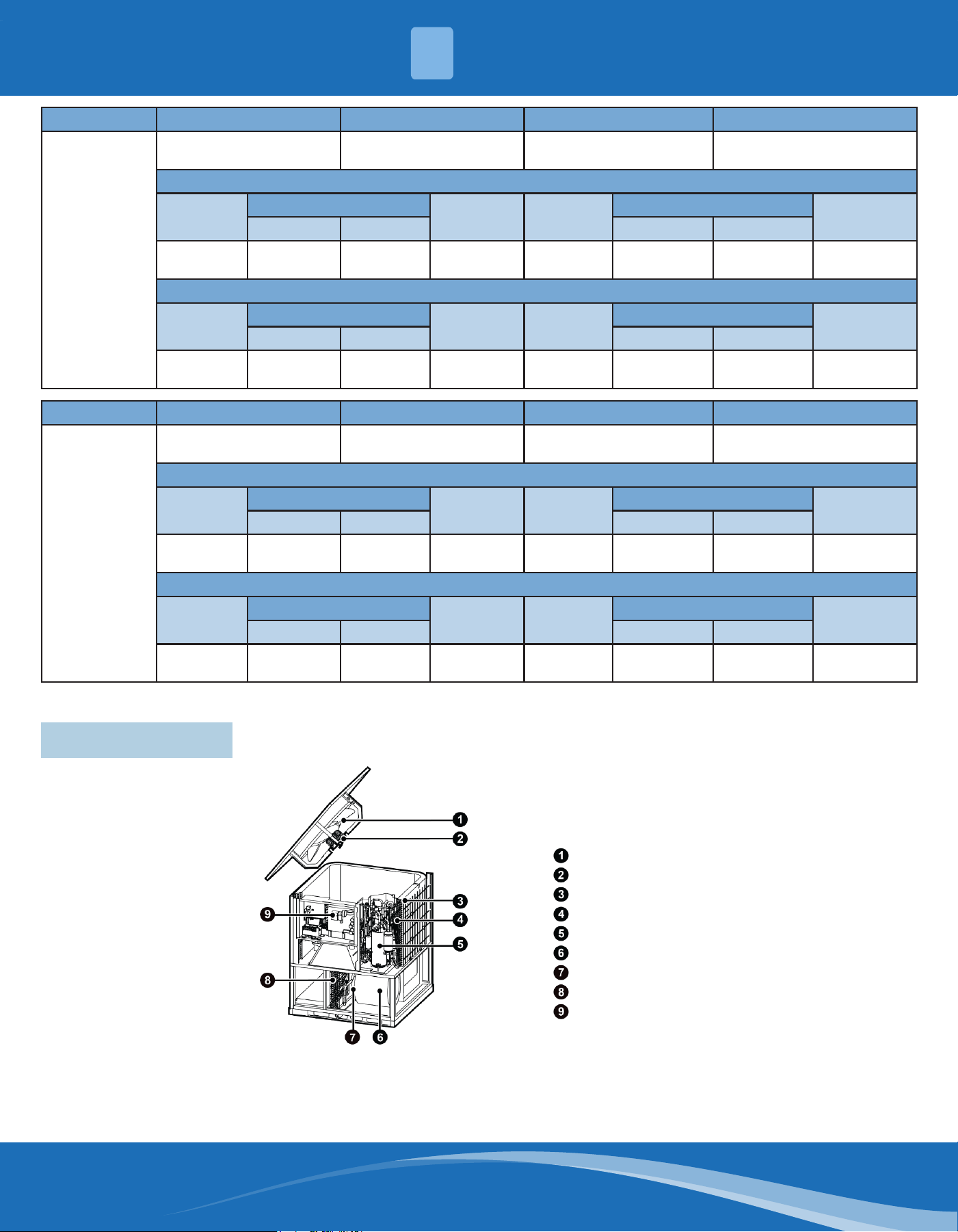
Fig. 2.1
2.2 Operating Range
Outdoor Ambient Temperature Outdoor Temperatures
Cooling 23°F~125.6°F (-5°C~52°C)
Heating -22°F~75.2°F (-30°C~24°C)
2.3 Codes & Regulations
This product is designed and manufactured to comply with national codes. It is the installer’s responsibility to install
the product in accordance with such codes and/or any prevailing local codes/regulations. MRCOOL® assumes no
responsibilities for equipment installed in violation of any codes or regulations.
2.4 Physical Dimensions
Fig. 2.2
mrcool.com 6
6
Note: Above diagrams may be dierent from the actual model.
UNIT OVERVIEW & FEATURES
2
Models A B C D
MDPH18048D
MDPH18060D
49-1/4 in.
1250 mm.
44 in.
1120 mm.
44 in.
1120 mm.
2-1/2 in.
65 mm.
Side Air Vents
E
Size of Air Return
G I
Size of Air Supply
K
F H J L
4 in.
101 mm.
15-3/8 in.
390 mm.
16-1/2 in.
420 mm.
3-3/8 in.
87 mm.
4 in.
101 mm.
15-3/8 in.
390 mm.
11-3/4 in.
300 mm.
6-1/2 in.
166 mm.
Bottom Air Vents
M
Side of Air Return
O R
Size of Air Supply
S
N P Q T
7-7/8 in.
199 mm.
28 in.
711 mm.
9 in.
228 mm.
3-3/4 in.
96 mm.
6-1/2 in.
166 mm.
11-3/4 in.
300 mm.
15-3/8 in.
390 mm.
4 in.
103 mm.
Models A B C D
MDPH18024D
MDPH18036D
49-1/4 in.
1250 mm.
44 in.
1120 mm.
35-7/16 in.
900 mm.
2-1/2 in.
65 mm.
Side Air Vents
E
Size of Air Return
G I
Size of Air Supply
K
F H J L
4-7/16 in.
113 mm.
17-8/16 in.
445 mm.
16-9/16 in.
420 mm.
3-7/16 in.
87 mm.
3-15/16 in.
101 mm.
15-6/16 in.
390 mm.
11-13/16 in.
300 mm.
6-3/16 in.
157 mm.
Bottom Air Vents
M
Side of Air Return
O R
Size of Air Supply
S
N P Q T
5-14/16 in.
149 mm.
23-1/16 in.
586 mm.
8-10/16 in.
219 mm.
3-11/16 in.
93 mm.
6-3/16 in.
156 mm.
11-14/16 in.
302 mm.
13-12/16 in.
350 mm.
3-10/16 in.
92 mm.
2.5 Main Parts
Fig. 2.3
Condensate fan
Condensate motor
Condenser assem
Service valves
Compressor
Evaporation fan
Evaporation motor
Evaporator assem
Electric box assem
mrcool.com7
PRE-INSTALLATION
3
3.1 Product Verication & Replacement Parts
Product Verication:
Upon receiving the product, check for any damage from transportation. Shipping damage is the responsibility of
the carrier. Verify the model number, specications and accessories are correct prior to installation. MRCOOL®
will not accept claims from dealers for transportation damage or installation of incorrectly shipped units.
Replacement Parts:
When reporting shortages or damages, or ordering repair parts, give the complete product model and serial
numbers as stamped on the product. Replacement parts for this product are available through your contractor
or local distributor.
3.2 Location Selection Requirements
1. The unit must be installed where it is strong enough to withstand the weight of the unit and xed securely,
otherwise the unit may fall over.
2. Do not install where there is danger of a combustible gas leakage.
3. Do not install the unit in a place with leakage of ammable gas.
WARNING
Select an installation location according to the following conditions:
1. Where noise and air ow produced by the air conditioner will not disturb the neighbors.
2. Select a location that is safe and away from animals and plants. If not, add safety fences to protect the unit.
3. Install in a place with good ventilation. Make sure the air conditioner stays in a well-ventilated place with no
obstacles nearby that may obstruct the air inlet and outlet.
4. The installation location should be able to withstand the weight and vibration of the air conditioner and allow
the installation to be carried out safely.
5. Avoid installing at a place with leakage of ammable gas, oil smoke, or corrosive gas.
6. Keep it away from strong wind because strong wind may aect the condenser fan and lead to insucient air
ow volume,thus aecting the unit’s performance.
7. Away from any object that may cause the air conditioner to generate noise.
8. Install the air conditioner at a place where condensate can be easily drained.
9. Do not install the air conditioner near the bedroom, otherwise the noise of the unit may be disturbing to
building occupants.
10. Do not install the unit where water, ice, or snow from overhang or roof may damage or ood the unit.
11. Do not install the unit in a corrosive environment, otherwise it may negatively aect its lifespan and performance.
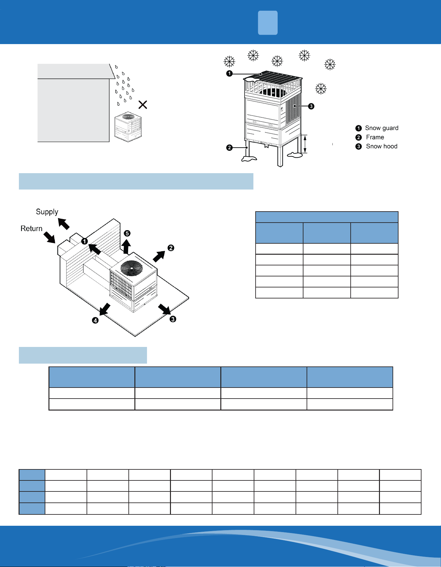
12. Installation requirements in snowy areas:
a. Install the air conditioner on a stand a minimum of 20in. (500mm) or higher than the expected snowfall to
prevent it from being covered by snow.
b. Attach snow hood and snow guard.
c. Do not install the air conditioner in a place where a snowdrift is likely.
d. Remove the air inlet grille to prevent snow from accumulating on it.
mrcool.com 8
8
PRE-INSTALLATION
3
3.3 Installation Location Dimensions & Clearances
Installation Clearances
Dimensions
(Minimum)
in. mm.
1 24 610
2 8 203
3 20 508
4 24 610
5 60 1524
Note: Refer to local code requirements
for additional clearance requirements.
For best performance of the unit, ensure its installation space meets the following installation dimensions.
Note: Above diagram may be dierent from actual model.
20in. (500mm)
Fig. 3.1
Fig. 3.2
3.4 Minimum Room Area
No.
Refrigerant Perfusion
lbs (kg)
Minimum Room Area
(m
2
)
Minimum Room Area
(ft
2
)
1 9.67 (4.25) 12.7 135.9
2 12.8 (5.8) 17.3 185.5
Notes:
1. The room area is calculated according to the height of 7.2ft (2.2m). Minimum room height is 7.2ft (2.2m).
2. This is only applicable to a single room.
3. Correct the minimum room area of the space (Amin) by multiplying Amin by the altitude adjustment factor (AF)
based on the building site ground level altitude (Halt), as measured in meters.
Halt 0 200 400 600 800 1000 1200 1400 1600
AF 1 1 1 1 1.02 1.05 1.07 1.1 1.12
Halt 1600 1800 2000 2200 2400 2600 2800 3000 3200
AF 1.12 1.15 1.18 1.21 1.25 1.28 1.32 1.36 1.4
mrcool.com9
PRE-INSTALLATION
3
3.5 Minimum Circulation Airow
Model Minimum Circulation Airow (m
3
/h)
MDPH18024D 417
MDPH18036D 417
MDPH18048D 569
MDPH18060D 569
3.6 Refrigerant Sensor
The unit is equipped with a refrigerant sensor. The sensor has a lifetime of 15 years.
At the end of lifetime or when the sensor faults, the mainboard will display the error code of “FE”, and emit an
alarm sound, the blower motor will turn on, and the compressor will shut down. If the sensor detects a refrigerant
leak, the mainboard will display the error code of “EA”, and emit an alarm sound, the blower motor will turn on,
and the compressor will shut down.
The blower motor will keep running and the system cannot be operated until the leak is repaired.
If the refrigerant sensor is damaged, the sensor can only be replaced with the particular sensor specied by
MRCOOL®. Replace the refrigerant sensor as follows:
Where a single remote refrigerant sensor is used in a room with multiple units, all units in the room, which do not
have a dedicated refrigerant detection system, shall take the same actions. When an ITE Cooling Appliance or a
Partial Unit’s Refrigerant Detection System for an appliance’s refrigerant circuit resets to a safe condition, the unit
should not be allowed to initiate normal operation until all refrigerant detection systems in the circulation airow
have been reset.
Where a single remote refrigerant detection system sensor is used in a room with multiple units, this requirements
shall apply to all units in the room which do not have a dedicated leak detection system installed. The unit must
be powered on except during servicing.
Continuous air circulation is required for proper functioning. Unit must be powered on except during servicing.
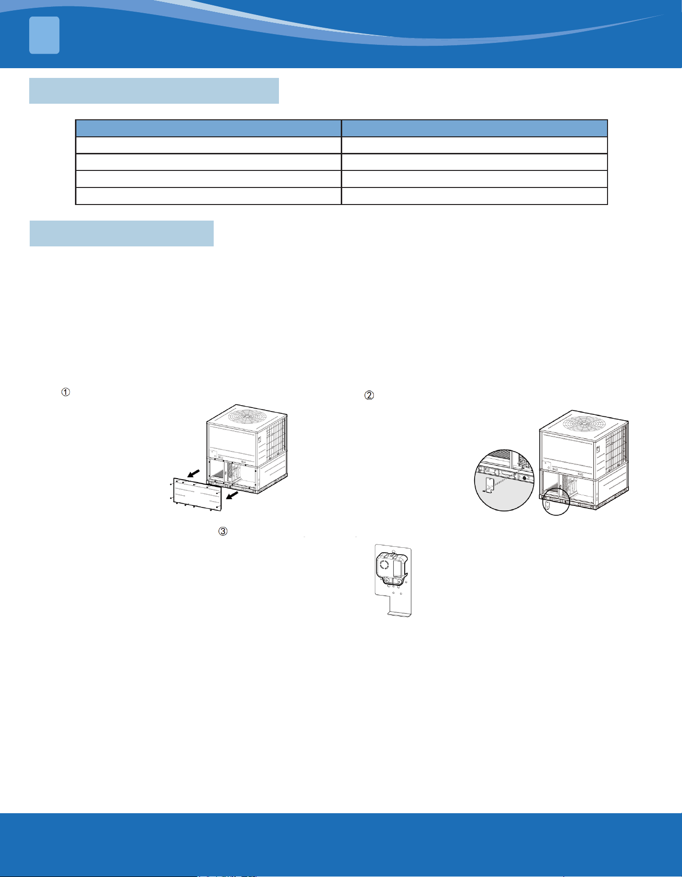
Remove the side plate.
Remove the holder.
Replace the refrigerant leakage sensor with a new one.
mrcool.com 10
10
UNIT INSTALLATION
4
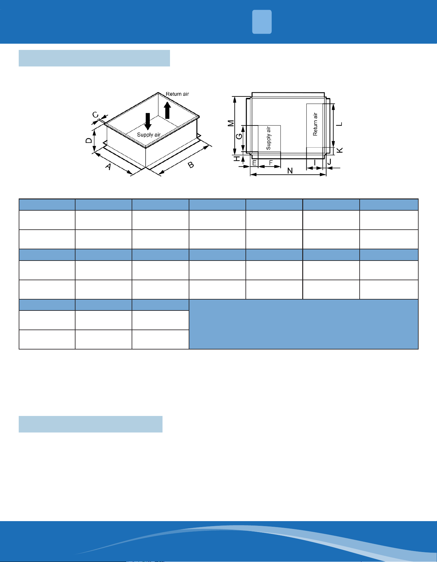
4.1 Curb-Mounted Installation
1. Install curb. (Note: MRCOOL does not supply roof curb. Refer to the following gure for roof curb reference
dimensions.) Prior to fabrication, conrm the reference dimensions meet the needs of the application.
in. (mm.)
Unit: in (mm)
Fig. 4.1
Models A B C D E F
MDPH18024D
MDPH18036D
29 in.
736 mm.
38-7/16 in.
976 mm.
1 in.
25 mm.
14 in.
356 mm.
4-1/4 in.
109 mm.
11-7/8 in.
302 mm.
MDPH18048D
MDPH18060D
37-5/8 in.
956 mm.
38-7/16 in.
976 mm.
1 in.
25 mm.
14 in.
356 mm.
4-11/16 in.
119.5 mm.
11-13/16 in.
300 mm.
G H I J K L
MDPH18024D
MDPH18036D
13-3/4 in.
350 mm.
1-3/4 in.
45 mm.
8-5/8 in.
219 mm.
1-3/4 in.
46 mm.
4 in.
102 mm.
23 in.
586 mm.
MDPH18048D
MDPH18060D
15-3/8 in.
390 mm.
2-3/16 in.
56 mm.
8-3/4 in.
223 mm.
2-3/16 in.
55 mm.
5-1/4 in.
133 mm.
29-1/2 in.
750 mm.
M N
MDPH18024D
MDPH18036D
30-15/16 in.
786 mm.
40-3/8 in.
1026 mm.
MDPH18048D
MDPH18060D
39-5/8 in.
1006 mm.
40-3/8 in.
1026 mm.
4.2 Pad-Mounted Installation
10
2. Field fabricate ductwork inside curb and secure supply and return ducts to roof curb and building structure.
3. Rig and place unit. (See 4.3 Rigging & Lifting)
4. Convert unit to vertical duct connection.
5. Install condensate drain piping.
6. Make electrical connections.
1. Prepare pad and unit supports.
2. Rig and place unit. (See section 4.3 Rigging & Lifting)
3. Convert unit to horizontal duct connection.
4. Field fabricate ductwork at unit duct openings.
5. Install condensate drain piping.
6. Make electrical connections.
mrcool.com11
UNIT INSTALLATION
4
4.3 Rigging & Lifting
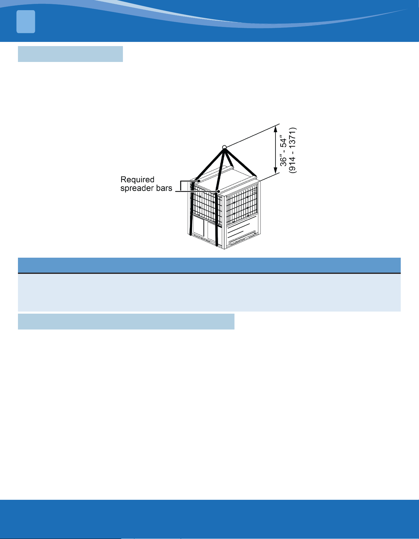
Do not remove the unit’s package materials before installation. Keep unit upright and do not drop. Rig the unit by
attaching chain or cable slings to the lifting holes in base rails.
Place the unit on roof curb and maintain the clearance between the roof curb and the base rail inside at 1/4 inch.
(6.4mm)
After unit is in position, remove rigging skids and package materials.
Fig. 4.3
1. Spreader bars are required in order to prevent rigging straps from damaging the unit.
2. All panels must be in place when rigging.
3. The height between the top of the unit and the rigging cables’ connection point should be 36-54 in.
(914-1371mm).
NOTICE
4.4 Horizontal Duct and Vertical Duct Conversion
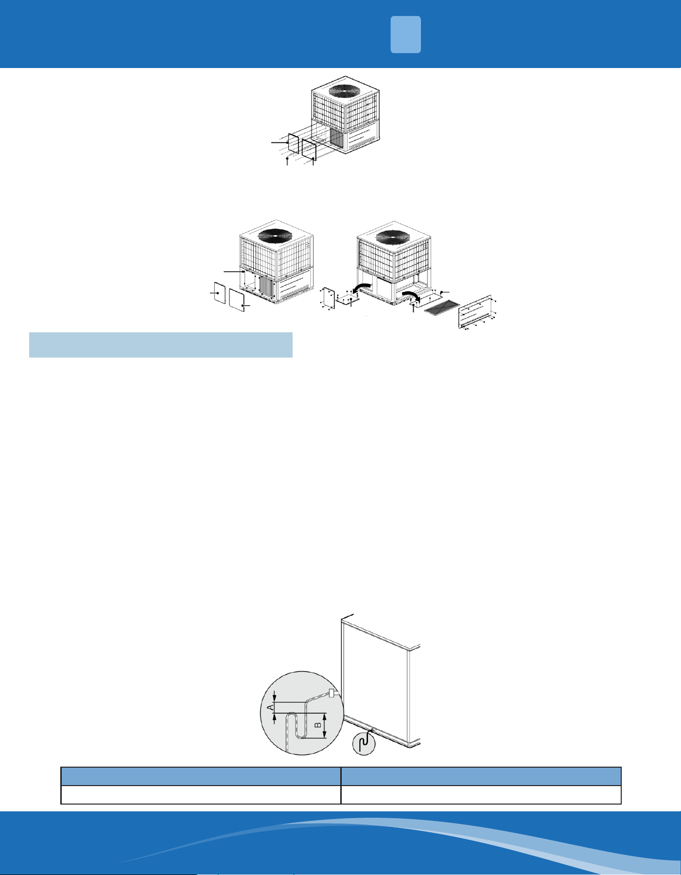
• To convert to a horizontal duct conguration, remove the screws from the side duct opening covers (see Figure
4.4) and remove the covers.
• To convert to a vertical duct conguration, remove the screws from the base pan duct opening covers (see
Figure 4.5) and remove the covers.
mrcool.com 12
12
UNIT INSTALLATION
4
Fig. 4.4
Fig. 4.5
4.5 Installation of Condensate Pipe
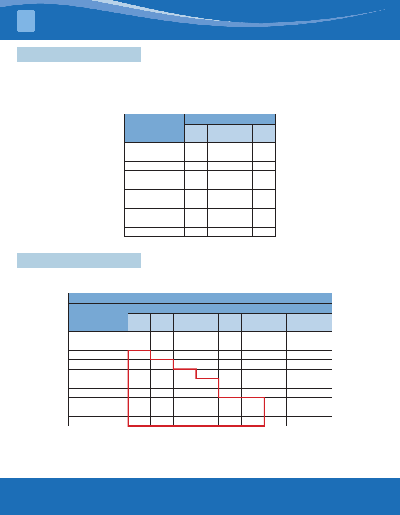
1. The condensate drain side is pitched lower than the opposite side. See gure below.
2. When shipped out from the factory, both the condensate outlets are blocked by a rubber plug. Remove the
plug before installation.
3. Condensate removal is performed by attaching a PVC pipe to the drain pan and terminated in accordance with
local or state Plumbing/HVAC codes.
4. The condensate pipe shall be installed with an inclining angle of 5~10°, so as to facilitate the drainage of
condensate.
5. Since the inside of the unit is in a negative pressure status, it is required to set up a backwater elbow. The
requirement is: A=B≥P/.4in+.8in (A=B≥P/10mm+20mm). P is the absolute pressure inside the unit; in pascals
(Pa).
6. After the electrical installation is completed, test the drainage system.
7. Do not connect the condensate drain pipe into a waste pipe or other pipelines likely to produce a corrosive or
peculiar smells, as the smell could move indoors or corrupt the unit.
8. Do not connect the condensate drain pipe with a rain pipe as it may cause rain water ooding, potentially
creating property loss or personal injury.
9. The condensate drain pipe should be connected to a special drain system for the unit.
Model Drain Connection Size (inch/mm)
All Models 3/4 in / 19.05 mm (NPT)
Condensate
Fig. 4.6
Remove supply
air cover
Remove sheet
metal screws
Remove return
air cover
Sheet metal
screws
Supply air
cover
Return air
cover
Supply
air cover
Return
air cover
Sheet metal
screws
mrcool.com13
UNIT INSTALLATION
4
4.6 Dip Switch Instruction
During initial installation, check DIP switch SA1, which may be set to the default 0000. To ensure proper
functionality with a 24V thermostat, this setting must be changed to 1111. NOTE: 0 means dip switch to
‘on’, 1 means dip switch equals the number.
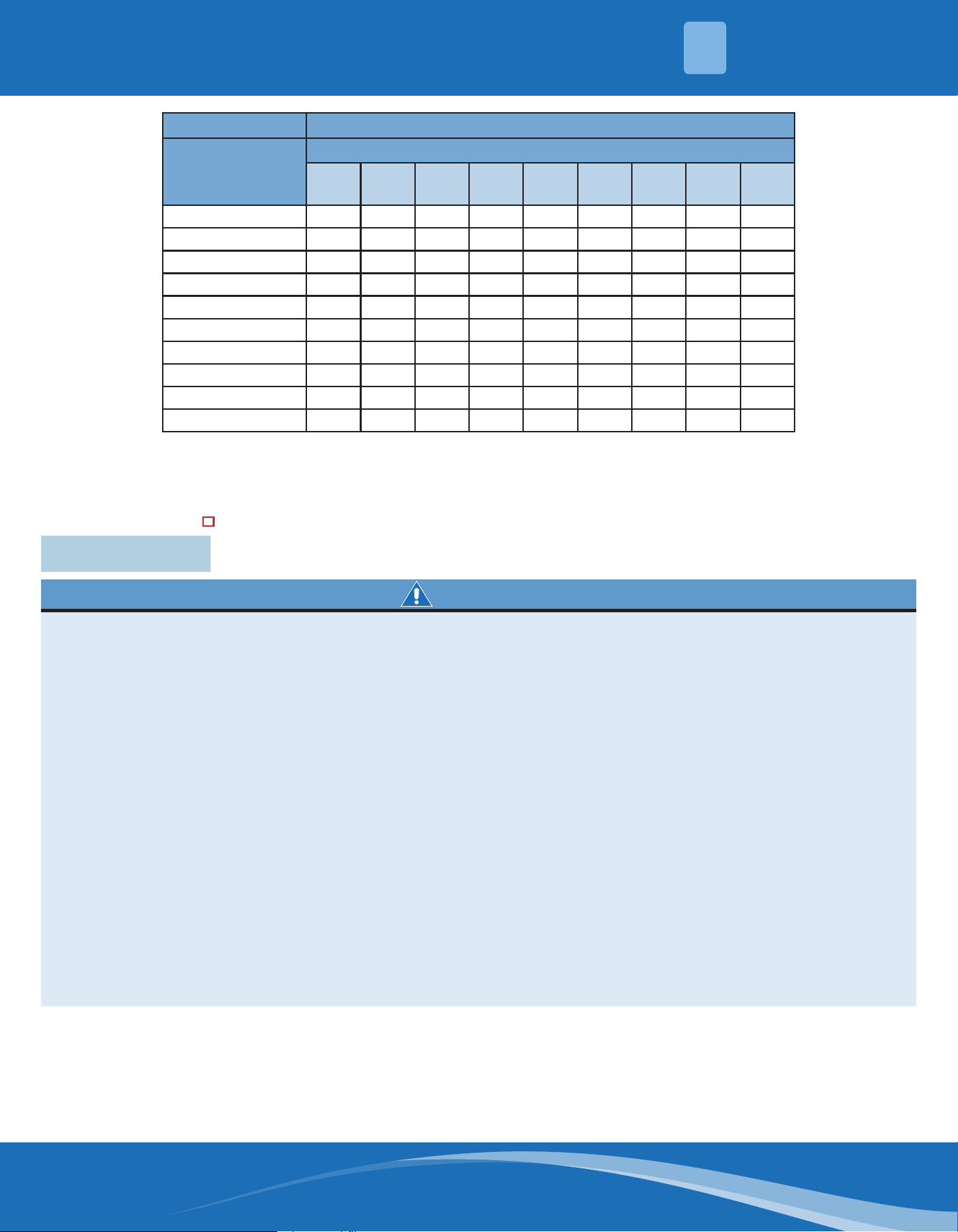
4.7 Fan Performance Data
External static pressure should stay within the minimum and maximum limits shown in the table below in order
to ensure proper operation of both cooling, heating, and electric heating operation.
Setting dierent positions of the dip switch will correspond to dierent speeds. The relationship between the
combination and speeds are as follows:
Level
Dip Switch SA1
4 3 2 1
Speed 4 0 1 0 0
Speed 5 0 1 0 1
Speed 6 0 1 1 0
Speed 7 0 1 1 1
Speed 8 1 0 0 0
Speed 9 1 0 0 1
Speed 10 1 0 1 0
Speed 11 1 0 1 1
Speed 12 1 1 0 0
Speed 13 1 1 0 1
Note: 0 means dip switch to “on”, 1 means dip switch to the number.
Model MDPH18024D, MDPH18036D
Level
Static Pressure: Inches W.C. (Pa)
0
(0)
0.1
(25)
0.2
(50)
0.3
(75)
0.4
(100)
0.5
(125)
0.6
(150)
0.7
(175)
0.8
(200)
Speed 4 (CFM) 1216 / / / / / / / /
Speed 5 (CFM) 1293 / / / / / / / /
Speed 6 (CFM) 1368 1264 / / / / / / /
Speed 7 (CFM) 1447 1348 1230 / / / / / /
Speed 8 (CFM) 1501 1436 1327 1195 / / / / /
Speed 9 (CFM) 1506 1464 1417 1383 / / / / /
Speed 10 (CFM) 1498 1466 1423 1378 1280 / / / /
Speed 11 (CFM) 1514 1472 1424 1385 1344 1303 / / /
Speed 12 (CFM) 1505 1467 1420 1375 1340 1303 1258 / /
Speed 13 (CFM) 1510 1463 1424 1380 1340 1297 1258 1216 /
mrcool.com 14
DUCTWORK
5
Model MDPH18048D, MDPH18060D
Level
Static Pressure: Inches W.C. (Pa)
0
(0)
0.1
(25)
0.2
(50)
0.3
(75)
0.4
(100)
0.5
(125)
0.6
(150)
0.7
(175)
0.8
(200)
Speed 4 (CFM) 1850 / / / / / / / /
Speed 5 (CFM) - 1780 / / / / / / /
Speed 6 (CFM) - 1870 / / / / / / /
Speed 7 (CFM) - - 1830 / / / / / /
Speed 8 (CFM) - - 1870 / / / / / /
Speed 9 (CFM) - - - 1860 / / / / /
Speed 10 (CFM) - - - - 1900 / / / /
Speed 11 (CFM) - - - - - 1880 1790 / /
Speed 12 (CFM) - - - - - 1980 1880 1804 1730
Speed 13 (CFM) - - - - - 2030 1930 1854 1780
Note:
1) “ / “ denotes the static pressure is out of range. Air volume drop may aect the performance and reliability.
2) “ - “ denotes the air volume is out of range, may lead to overload, and cause unstable operation of the fan motor.
3) The red-line frame “ ” indicates electric heating is allowed.
1. Field ductwork must meet the National Fire Protection Association NFPA 90A, NFPA 90B, and any applicable
local ordinance.
2. Sheet metal ductwork ran in unconditioned spaces must be insulated and covered with a vapor barrier.
Fibrous ductwork may be used if it is constructed and installed in accordance with SMACNA Construction
Standard on Fibrous Glass Ducts. Ductwork must comply with the National Fire Protection Association
as tested by U/L Standard 181 for Class I Air Ducts. Check local codes for requirements on ductwork and
insulation.
3. Duct systems must be designed within the same range of external static pressure as the unit it is designed
to operate against. It is important the system airow is adequate. Ensure supply and return ductwork,
grills, special lters, accessories, etc. are accounted for in total resistance. See fan performance data in this
manual.
4. Do not operate the unit without all ductwork completed.
5. Do not operate the unit without all ductwork attached.
6. Inadequate ductwork that restricts airow can result in improper performance and compressor or heater
failure. Ductwork needs to be constructed in a manner that limits restrictions and maintains suitable air
velocity. Ductwork must be sealed to the unit in a manner that will prevent leakage.
7. Return Ductwork: Do not terminate the return ductwork in an area that can introduce toxic or
objectionable fumes/odors into the ductwork. The return ductwork needs to be set into the air handler
bottom (upow conguration).
8. Return Air Filters: Each installation must include a return air lter. This ltering must be performed at the
air handler or externally, such as with a return air lter grille.
WARNING
5- Ductwork
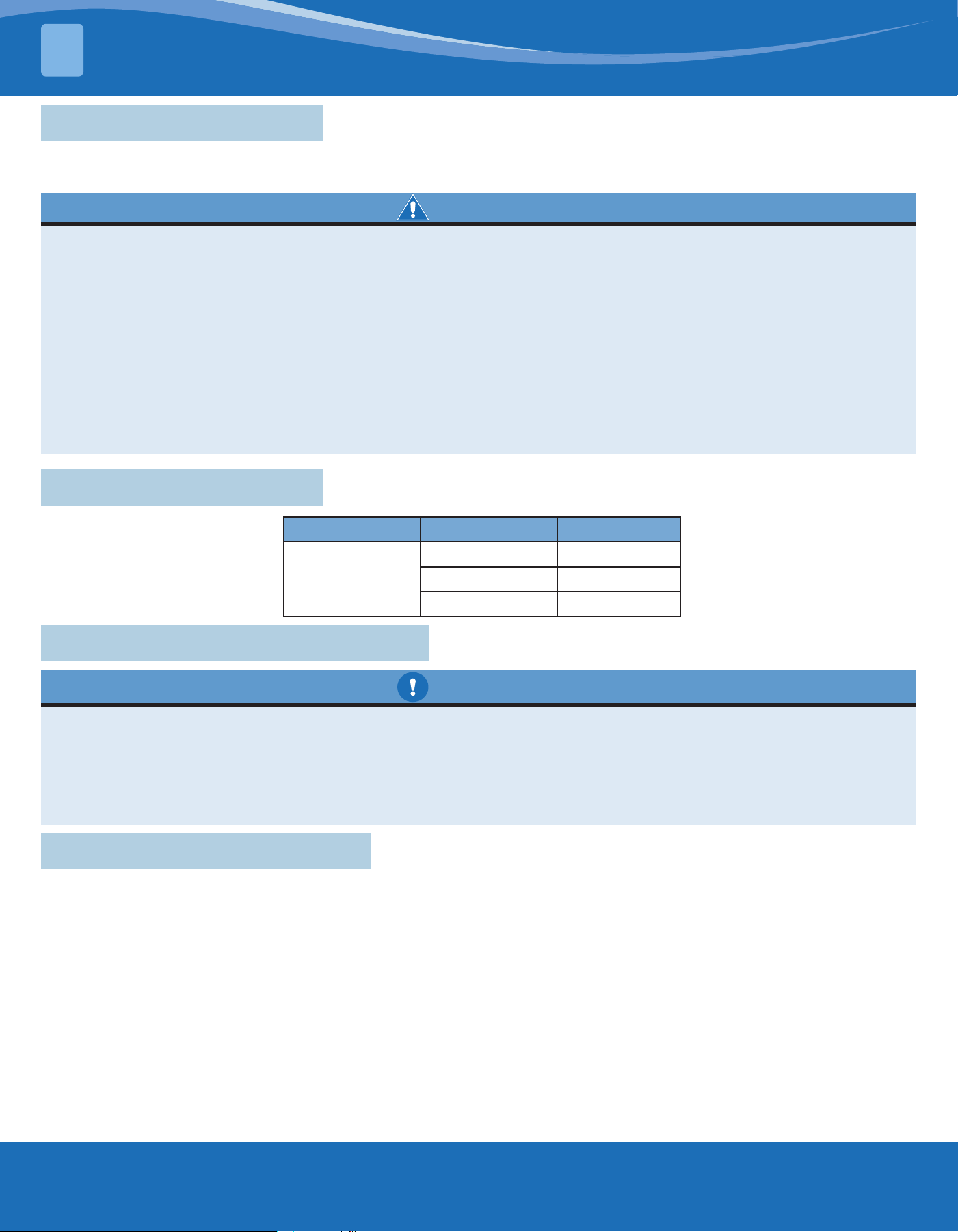
mrcool.com15
6.1 Electric Heater Safety
1. Refer to the “Electric Heat Kit Installation” section of this manual and the instructions provided with the
heat kit for the correct installation procedure.
2. The electrical characteristics of the unit, electric heat kit, and supply power should be identical. If installing
this option, the only heat kits that can be used are indicated below. Do not use an electric heat kit other
than those recommended.
3. Pay attention to the switch order of the electric heating and indoor fan during installation and debugging.
The fan must be turned on before electric heating is in operation. Make sure to stop the indoor fan after
the electric heating is turned o to avoid malfunctions.
4. Refer to the “Fan Performance Data” section of this manual on page 13, otherwise it may cause abnormal
electric heating and increase the risk of dry burning.
5. There should be at least 5ft (1.524m) between electric heating and the supply air duct, and should be at
least 1ft (0.304m) away from other combustible materials or walls.
WARNING
This unit does not oer a factory-installed electric heating function. Electric heat is available as an accessory. Refer
to the installation instructions provided with the heat kit for the correct installation procedure.
ELECTRIC HEATER
6
6.2 Compatible Heat Kits
Model Number Heat Kit Model Description
All Models
MDPHK06D 5kW Heat Kit
MDPHK09D 9kW Heat Kit
MDPHK12D 12kW Heat Kit
CAUTION
1. Ensure power supply is disconnected prior to installing the heat kit.
2. Provide strain relief and conductor protection at the supply wire entrance into the cabinet.
3. Use copper conductors only.
4. Installation must follow national electric code and other applicable codes.
5. If the unit is installed in an enclosed area, such as a garage or utility room, with a carbon-monoxide
producing appliance, ensure the area is properly ventilated.
6.3 Heat Kit Installation Precautions
1. Refer to the table above for the appropriate heat kit.
2. Check for any physical damage. Do not install a damaged heat kit.
3. Remove the access panel from the unit.
4. Remove the cover plate from the unit.
5. Slide the heat kit into the slot and secure the element plate with the previously removed screws.
6. Insert power leads into the circuit breaker lugs.
7. Connect the ground wire to the ground lug.
8. Knock out the hole in the stand column. If a circuit breaker is not installed, do not knock out the holes. It could
negatively aect the unit’s performance and reliability.
9. Replace the access panel and check operation.
6.4 Heat Kit Installation Steps
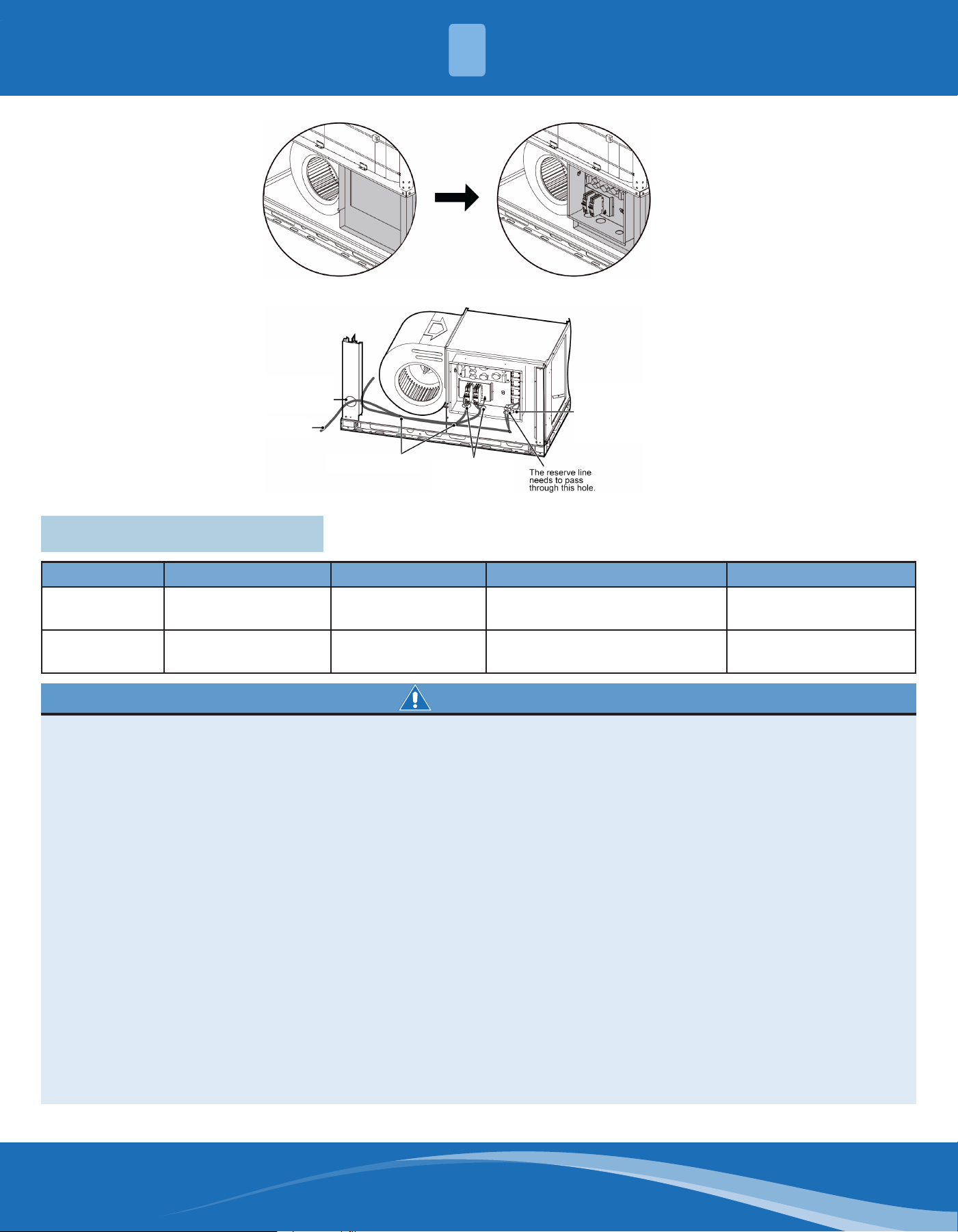
mrcool.com 16
10. Connect power cords and reserve lines.
Fig. 6.1 Fig. 6.2
The power cord must pass
through this hole.
The reserve line and the
electric heating line must
be connected here.
The power cord must pass
through the holes.
Fig. 6.3
The power
cord must be
xed by wire
clamps.
Power Cord
7.1 Electrical Parameters
Unit Model Power Supply Fuse Capacity (A) Max. Over-Current Prot. (A) Min. Circuit Amp. (A)
MDPH18024D
MDPH18036D
208/230V-1Ph-60Hz 40 40 35
MDPH18048D
MDPH18060D
208/230V-1Ph-60Hz 45 45 39.1
ELECTRICAL INSTALLATION
7
The electrical installation for the unit should observe the following requirements:
1. The electrical installation must be conducted by professionals in compliance with local laws, regulations,
and the instructions in this manual. The electric circuit must be equipped with a circuit breaker and an air
switch with sucient capacity.
2. The unit’s operating power must be within the nominal range stated in the instruction manual. Use a
specialized power circuit for the air conditioner. Do not draw power from another power circuit.
3. The air conditioner circuit should be at least 1.5m (4.92ft) away from any ammable surfaces.
4. The external power cords, thermostat wires, and unit must be eectively xed in place.
5. The external power cords, thermostat wires, and unit can’t directly contact any hot objects. For example:
they must not contact chimney pipes, warm gas pipes, or other hot objects.
6. The external power cords, thermostat wires, and unit must not be squeezed. Never pull, stretch, or bend
the wires.
7. The external power cords, thermostat wires, and unit must not collide with any metal beam, edge on the
ceiling, or touch any metal burrs or sharp metal edges.
8. Connect wires by referring to the circuit diagram labeled on the unit or electric box. Screws must be
tightened. Slipped screws must be replaced by specialized at-head screws.
9. Wiring terminals should be connected rmly to the terminal board. Loose connections are forbidden.
10. The wire gauge of power cords must be large enough. Damaged power cords or other wires must be
replaced by specialized wires. Wiring must be done according to national wiring rules and regulations.
11. The unit has a heating four-way valve.
12. All wires must go through the tube.
WARNING
mrcool.com17
ELECTRICAL INSTALLATION
7
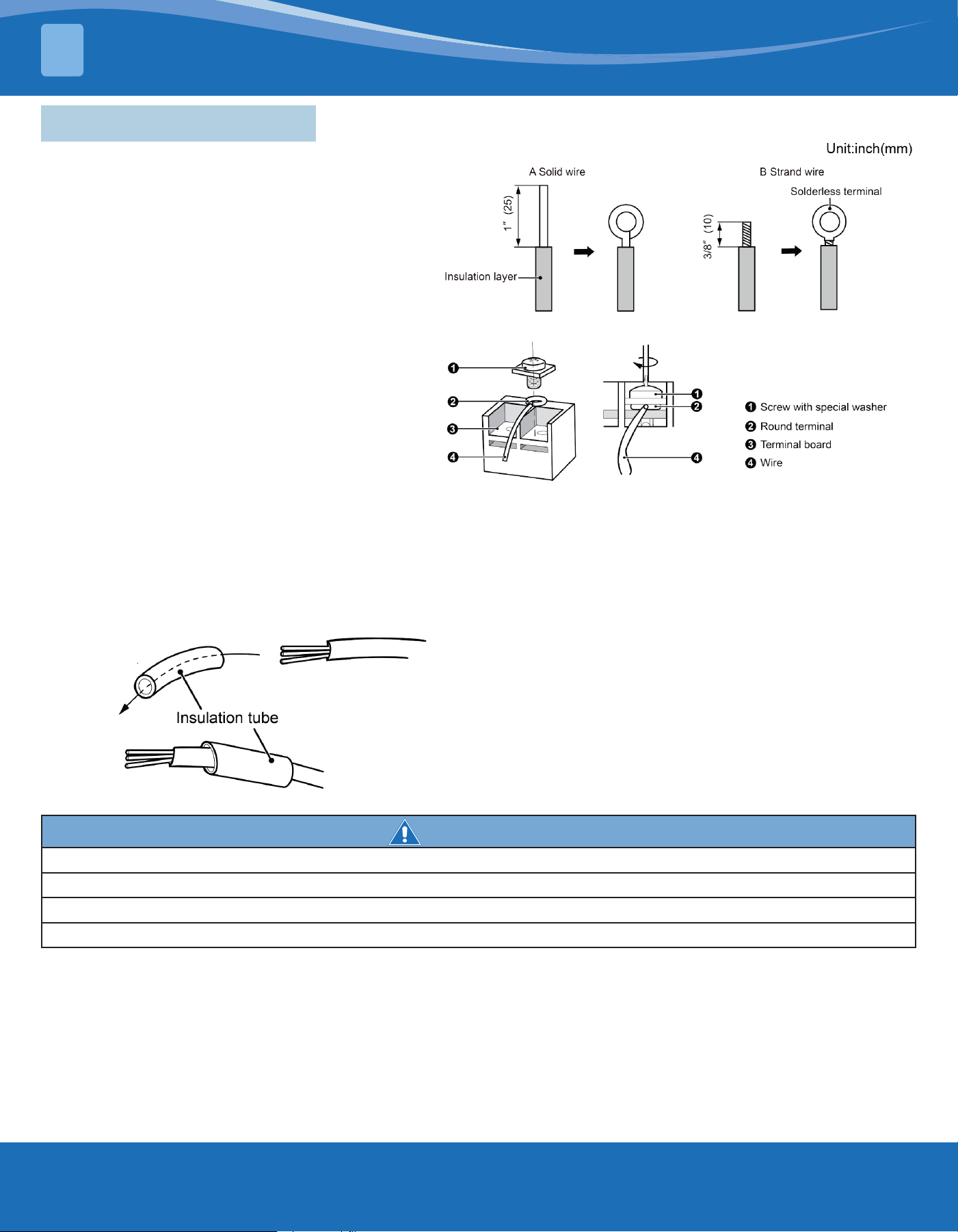
7.2 Terminal Connection
For solid wires (as shown below):
1) Use wire cutters to cut the wire end and peel away
about 1in (25mm) of the insulation layer.
2) Use a screwdriver to unscrew the terminal screw
on the terminal board.
3) Use pliers to bend the solid wire into a ring to t
the terminal screw.
4) Form a proper ring and attach it to the terminal
board. Use a screwdriver to tighten the terminal
screw.
For strand wires (as shown below):
1) Use wire cutters to cut the wire end and peel away
about 0.5in (10mm) of the insulation layer.
2) Use a screwdriver to unscrew the terminal screw
on the terminal board.
3) Use a round terminal fastener or clamp to x the
round terminal rmly on the peeled wire end.
4) Locate the round terminal conduit. Use a
screwdriver to replace and tighten the terminal
screw. (See Fig. 7.2)
Fig. 7.2
Fig. 7.1
How to connect the thermostat wires and power cords:
Lead the thermostat wires and power cords through the insulation tube, as shown in Figure 7.3 below.
Fig. 7.3
Note: Remember to change dip switch settings on SA1
to 1111.
WARNING
1. Before working, check whether the unit is powered on.
2. An incorrect wire connection may burn the electrical components.
3. Connect the wires rmly to the wiring box. Incomplete installation may lead to re hazard.
4. Ground wire should be connected.
mrcool.com 18
ELECTRICAL INSTALLATION
7
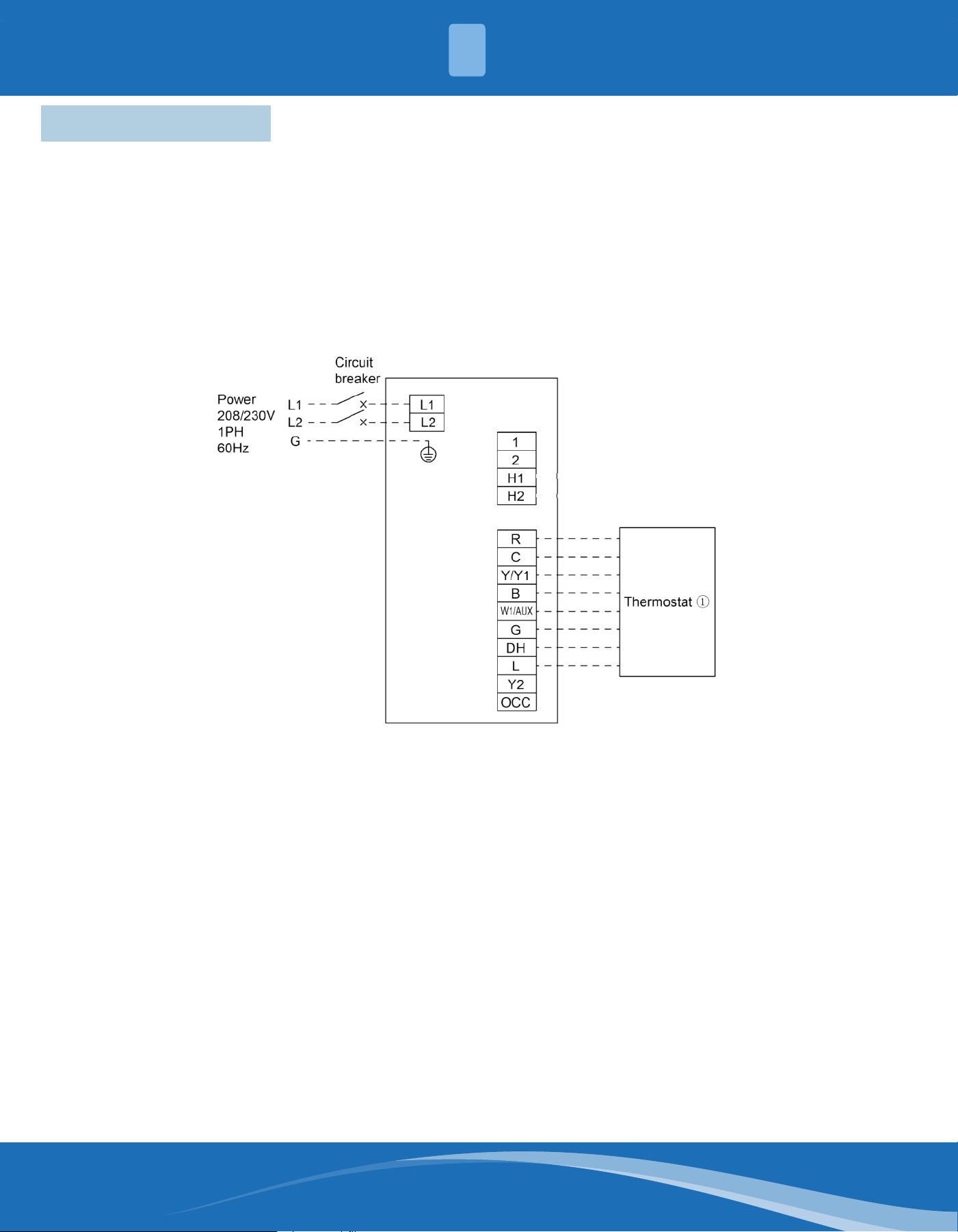
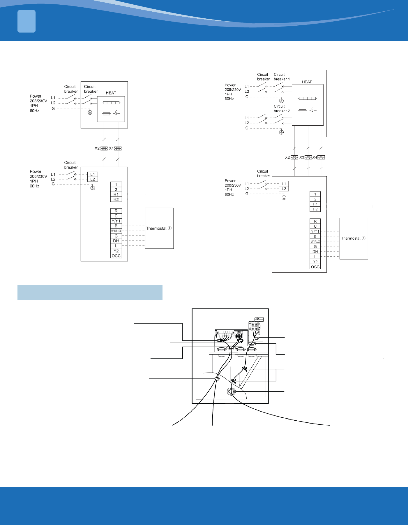
7.3 Wiring Diagram
Note:
1. The unit has been short-circuited. When the
emergency stop switch needs to be connected, remove
the corresponding short-circuit wire.
2. The unit can only be connected to a thermostat or
wired controller.
Note:
Y means compressor control signal
B is energized under the heating mode
and means 4-way valve control signal
W1 means heater control signal
R means 24V AC power supply
C means 24V common
G means indoor side fan signal
Without Electric Heater
Fig. 7.4
mrcool.com19
ELECTRICAL INSTALLATION
7
Note:
The unit can only be connected to a thermostat or the wired controller.
With Electric Heater
Fig. 7.5 (With MDPHK06D)
Fig. 7.6 (With MDPHK09D, MDPHK12D)
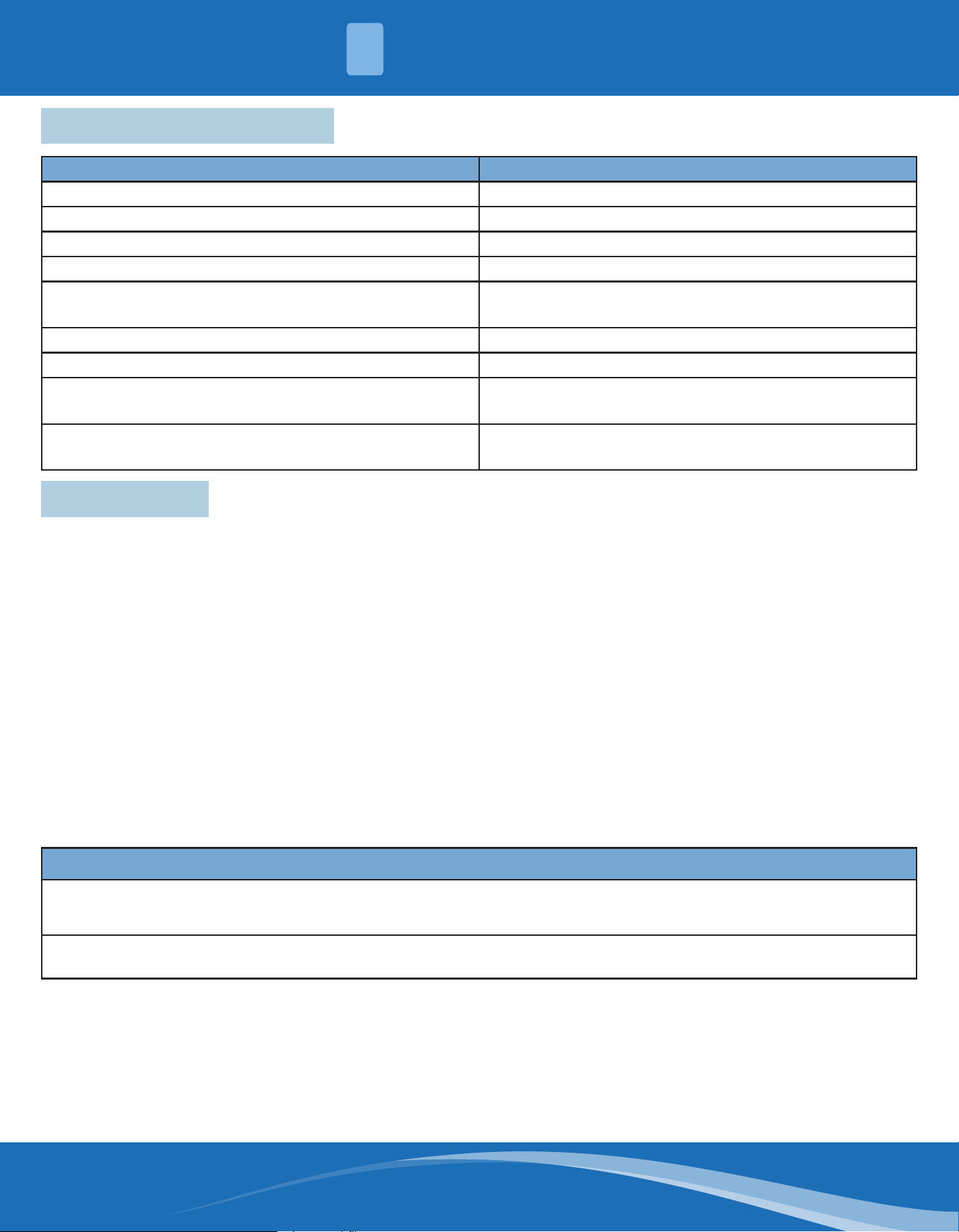
7.4 Engineering Wiring Diagram
Fig. 7.7
The emergency stop switch line and the wired
controller line should be xed by wire clamps.
The emergency stop switch line, the wired
controller line, and the thermostat line should
be through the hole and secured tightly.
The emergency stop switch line, the
wired controller line, and the thermostat
line should be through this hole.
The power cord must be xed by
wired clamps.
The power cord must be through
this hole and secured tightly.
The power cord must be xed by
wire clamps.
Enter power cord through the hole.
1. If there is no emergency stop switch, ignore additional wiring.
2. The unit can only be connected to a thermostat or a wired controller.
The thermostat line should
be xed by wire clamps.
Thermostat line Emergency stop
switch line
Power cord
Note:
mrcool.com 20
Enter power cord through the hole.
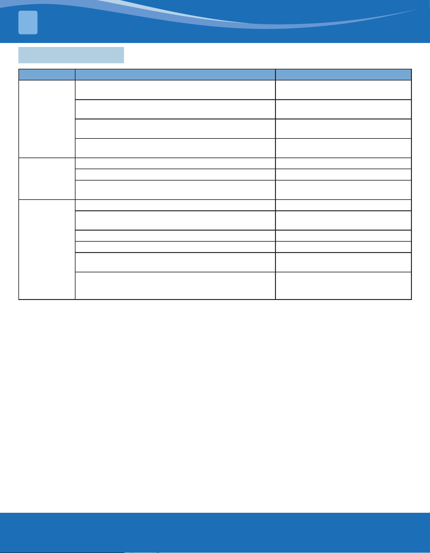
8.1 Post-Installation Check
Check Items Possible Events due to Improper Installation
Is the main body installed securely? The unit may fall down, vibrate, or produce noise.
Was the water leakage test performed? Cooling capacity may become unsatisfactory.
Is the unit well-insulated from the heat? Condensation and water drops may occur.
Does water drain easily? Condensation and water drops may occur.
Is the voltage consistent with what’s stated on the
nameplate?
The unit may fail or its components may burn.
Are the wires and pipes installed correctly? The unit may fail or its components may burn.
Has the unit been safely grounded? There is a risk of electrical leakage.
Do the wire specications comply with the
requirements?
The unit may fail or its components may burn.
Are there any obstacles blocking the air inlet and
outlet of the units?
Cooling capacity may become unsatisfactory.
Preparation before connecting the power:
1. The power should not be connected if the installation work has not been completed.
2. The control circuit must be correct and all the wires are rmly connected.
3. The inside of the unit should be clean. Take all irrelevant objects out, if there are any.
Operation after connecting the power:
1. If all the above works are nished, power on the unit.
2. If the outside temperature is more than 30°C (86°F), heating mode can’t be enabled.
3. Before test operation, make sure the unit is powered on and the compressor has been preheated for more than 8
hours. Touch the unit to check whether it’s normally preheated. Start the test operation after the unit is normally
preheated, otherwise compressor might be damaged. Debugging must be performed by professional technicians
or under the guide of professional technicians.
4. Make sure the unit can run normally.
5. If there’s a sound of liquid shock when the compressor is running, stop the air conditioner immediately. Wait until
the electric heating belt is heated enough, and then restart the air conditioner.
8.2 Trial Run
NOTICE
1. If a thermostat is used to turn o the unit and immediately turned on again, the compressor unit will need 3
minutes to restart. Even if the “ON/OFF” button on the thermostat is pressed, the compressor will not start up
right away.
2. If no display appears on the thermostat, check the connection wires between the unit and the thermostat to
verify they are connected.
TRIAL RUN & TROUBLESHOOTING
8
mrcool.com21
TRIAL RUN & TROUBLESHOOTING
8
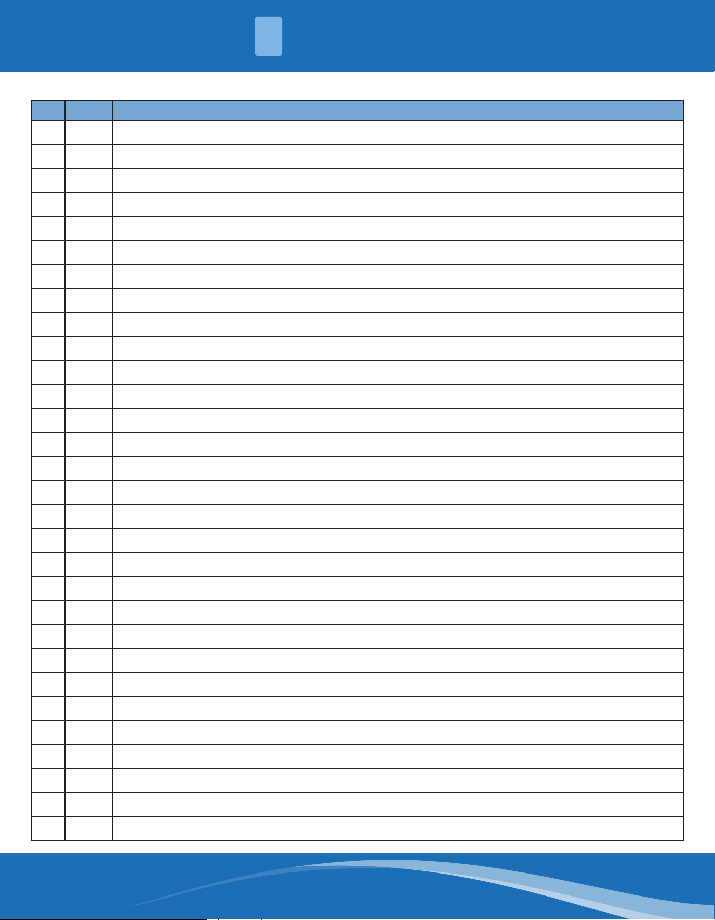
8.3 Troubleshooting
Failure Possible Cause Solution
The unit
cannot be
started.
The power supply does not connect or there is an
improper phase sequence.
Connect the power supply or change
to a random phase.
Electrical leakage of the unit is causing the leakage
switch to trip.
Contact the MRCOOL® Technical
Department at (270) 366-0457
The voltage is too low. Contact the MRCOOL® Technical
Department at (270) 366-0457
The control loop has a failure. Contact the MRCOOL® Technical
Department at (270) 366-0457
The unit
operates for
a while and
then stops.
Air outlet port or intake port is blocked. Remove the obstacles.
There is an obstacle in front of the condenser. Remove the obstacles.
The control loop is abnormal. Contact the MRCOOL® Technical
Department at (270) 366-0457
Poor cooling
eect.
Air lter is dirty. Clean the air lter.
Air outlet port or intake port of indoor/outdoor side is
blocked.
Move the obstacles.
Too many people or there is a heat source in the room. If possible, clear heat sources.
Doors or windows are open. Close windows and doors.
Refrigerant leakage. Contact the MRCOOL® Technical
Department at (270) 366-0457
Some model units have a high pressure switch welded
on the discharge pipe. When the switch goes into eect,
the power supply of the compressor will be shut o.
Find and manually reset the high
pressure switch welded on the
discharge pipe.
NOTE: If after performing the troubleshooting above and taking measures to resolve the problems, the unit is still
performing poorly, stop operation of the unit immediately and contact the MRCOOL® Technical Department at
(270) 366-0457. Only ask professional servicemen to check and repair the unit.
mrcool.com 22
TRIAL RUN & TROUBLESHOOTING
8
Code List:
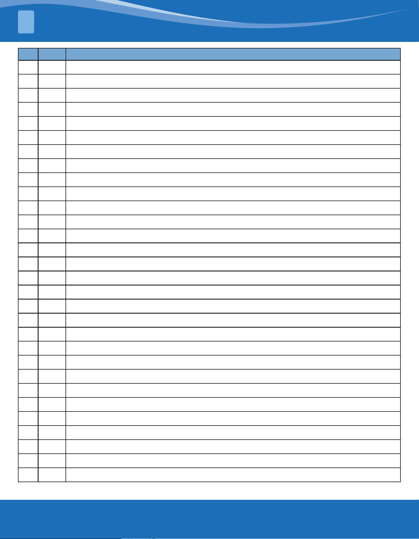
No. Code Error or Status
1 A1 Outdoor fan IPM module protection
2 A5 Outdoor condenser inlet pipe temperature sensor error
3 A6 Malfunction from fan driving part to main-control communication
4 A8 Overheat protection from fan radiator
5 A9 Fan radiator sensor malfunction
6 AA Fan AC current protection (input side)
7 Ab Fan drive board module reset
8 Ac Outdoor fan startup failure
9 Ad Outdoor fan out-of-phase protection
10 AE Outdoor fan current detecting circuit error
11 AF Fan PFC abnormality
12 AH Fan DC busbar overvoltage protection
13 AJ Outdoor fan non-synchronism protection
14 AL Fan DC busbar undervoltage protection
15 An Fan drive storage chip malfunction
16 AP Fan AC input voltage abnormality
17 Ar Fan driver board environment temperature sensor malfunction
18 AU Fan charge circuit malfunction
19 b2 Subcooler gas inlet temperature sensor error
20 b3 Subcooler gas outlet temperature sensor error
21 b4 Subcooler liquid outlet temperature sensor error
22 C0 Communication error between indoor unit and wired controller
23 C1 Indoor ambient temperature sensor error
24 C3 Outdoor condenser middle pipe temperature sensor error
25 C4 ODU jumper cap error
26 C6 Discharge temperature sensor error
27 C8 Compressor DIP switch/jumper cap error
28 C9 Compressor drive storage chip error
29 CA Inlet pipe temperature sensor of evaporator error
30 Cb Outlet pipe temperature sensor of evaporator error
mrcool.com23
TRIAL RUN & TROUBLESHOOTING
8
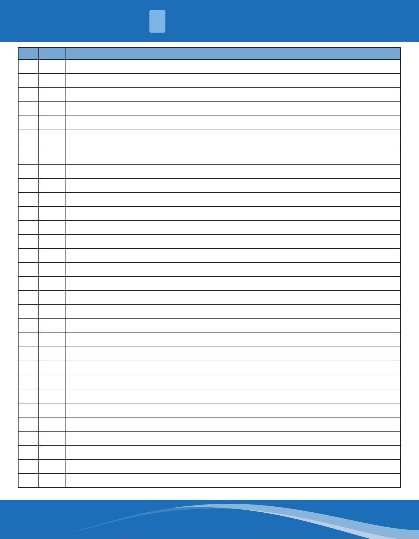
No. Code Error or Status
31 Cd Abnormal electrical level of selected port
32 CE Wired controller temperature sensor error
33 dJ AC phase sequence protection (phase loss or phase reversal)
34 E0 Indoor fan error
35 e1 High pressure sensor error
36 E1 System high pressure protection
37 E2 Freeze protection
38 e3 Low pressure sensor error
39 E3 Refrigerant lacking protection or system low-pressure protection
40 E4 Discharge protection
41 EA Refrigerant leakage
42 EE Memory chip read and write error
43 EH Electric heater operation error
44 EL Emergency operation stop
45 F3 Outdoor ambient temperature sensor error
46 FE Malfunction of refrigerant sensor
47 FJ Air outlet temperature sensor error
48 H5 Module current protection
49 H7 Compressor non-synchronism
50 HC PFC overcurrent error
51 L3 Outdoor fan 1 error
52 L4 Wired controller power supply circuit failure
53 L5 Wired controller power supply overcurrent protection
54 L6 Group-controlled IDU quantity inconsistency
55 LA Outdoor fan 2 error
56 Lc Startup failure
57 LE Compressor Stalling
58 LF Overspeed
59 oE Other error of compressor
60 P0 Drive module reset
mrcool.com 24
TRIAL RUN & TROUBLESHOOTING
8
No. Code Error or Status
61 P5 Overcurrent of compressor phase current
62 P6 Drive board communication error
63 P7 Module temperature sensor circuit error
64 P8 Module temperature protection
65 P9 AC contactor protection
66 PA ODU AC current protection
67 Pd Sensor connection protection (current sensor hasn’t been connected to the corresponding U
phase or V phase)
68 PE Temperature shifting protection
69 PF Drive board ambient temperature sensor error
70 PH High voltage protection of DC bus
71 PL Low voltage protection of DC bus
72 PP DC input voltage error
73 PU Capacitor charging error
74 q0 Low voltage protection or voltage drop error of inverter indoor fan drive dc bus
75 q1 High voltage protection of inverter indoor fan drive DC bus
76 q2 Inverter indoor fan AC current protection (input side)
77 q3 Inverter indoor fan drive IPM module protection
78 q4 Inverter indoor fan drive PFC protection
79 q5 Inverter indoor fan startup failure
80 q6 Inverter indoor fan out-of-phase protection
81 q7 Inverter indoor fan drive module reset
82 q8 Inverter indoor fan overcurrent protection
83 q9 Inverter indoor fan power protection
84 qA Inverter indoor fan drive current detecting circuit error
85 qb Inverter indoor fan non-synchronism protection
86 qC Main control and inverter indoor fan drive communication error
87 qd Inverter indoor fan drive module high temperature protection
88 qE Inverter indoor fan drive module temperature sensor error
89 qF Inverter indoor fan drive storage chip error
90 qH Inverter indoor fan drive charging circuit error
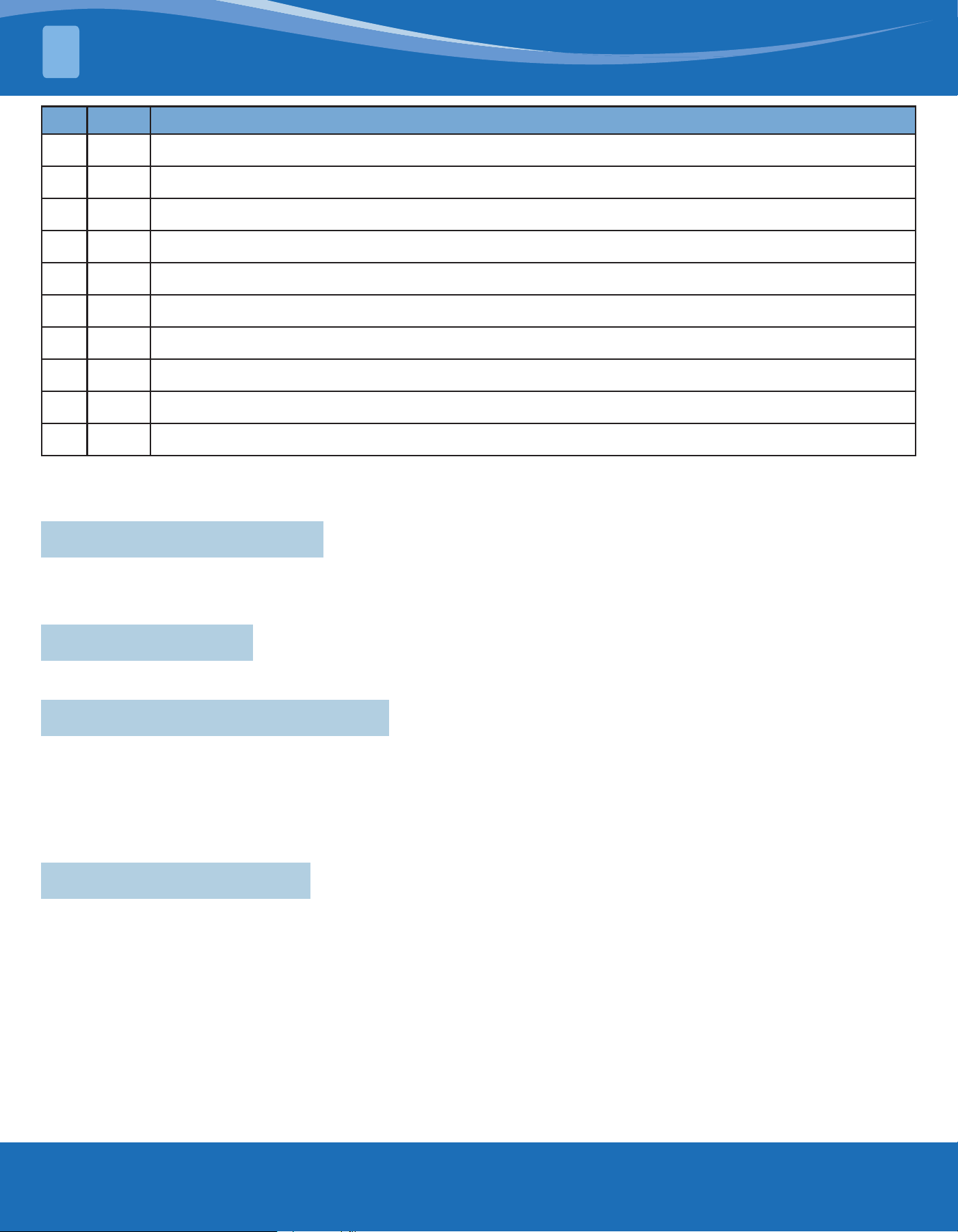
mrcool.com25
NOTE:
If several errors happen at the same time, error codes will show on the display repeatedly.
No. Code Error or Status
91 qL Inverter indoor fan drive AC input voltage abnormal protection
92 qo Inverter indoor fan drive electric box temperature sensor error
93 ap Inverter indoor fan drive AC input zero-crossing protection
94 U1 Compressor phase current circuit detecting error
95 U2 Compressor phase loss/phase reversal/out of phase
96 U9 Fan AC contractor protection or input zero crossing error
97 UL Outdooor fan overcurrent protection
98 UP Fan power protection
99 08 Defrosting
100 09 Oil return
9.1 Cleaning the Air Filter
1. Do not disassemble the air lter when cleaning it or unit failure can occur.
2. If the unit is used in a dusty environment, the air lter should be cleaned more frequently.
9.2 Drainage Pipe
Periodically check if the drainage pipe is blocked to allow for easy ow of the condensate water.
9.3 Cleaning the Heat Exchanger
• The heat exchanger should be cleaned regularly, at least every two months.
• Use a dust catcher with a nylon brush to clear the dust on the heat exchanger.
• If a compressed air source is available, it can also be used to clean the heat exchanger.
• Do not clean it with water.
9.4 Before Seasonal Use
• Check whether the air inlets and air outlets of the units are blocked.
• Check whether the ground connection is reliable or not.
• Check whether the air lter is properly installed.
• If the unit starts up after operating for a long time, it should be powered on for 8 hours before operation in
order to preheat the outdoor compressor.
• Check whether the outdoor unit is securely installed. If there is any problem, contact the MRCOOL® Technical
Department at (270) 366-0457.
MAINTENANCE
9

mrcool.com 26
MAINTENANCE
9
9.5 After Seasonal Use
• Disconnect power to the entire system.
• Clean the air lter and outer case of both units.
• Clean away any dust and obstacles.
• If the unit has rust, apply rust resistant paint to prevent the rust from growing.
9.6 Parts Replacement
Parts and components can be obtained, contact the MRCOOL® Technical Department at (270) 366-0457.
Note: When you are conducting an air tightness test and leakage test, do not mix oxygen, C
2
H
2
, or other dangerous
gases into the refrigerant circuit. Otherwise, it may lead to danger. Use nitrogen or refrigerant to conduct the test.
For appliances using A2L refrigerants, connected via an air duct system to one or more rooms, the supply and
return air should be directly ducted into the space. Open areas such as false ceilings shall not be used as a return
air duct eld-made refrigerant joints indoors should be tightness tested. The test method must have a sensitivity of
5 grams per year of refrigerant or better under a pressure of at least 0.25 times the maximum allowable pressure.
9.7 After-Sale Service
If there’s a quality defect or any other product-related issue, contact the MRCOOL® Technical Department at
(270) 366-0457.
9.8 Unventilated Areas
If appliances with A2L refrigerant connected via an air duct system to one or more rooms are installed in a room
with an area less than Amin, that room should have no continuously operating open ames (for example: an
operating gas appliance) or other potential ignition sources (for example: an operating electric heater or hot
surface). A ame-producing device may be installed in the same space if the device is provided with an eective
ame arrest.
Auxiliary devices that may be a potential ignition source should not be installed into the duct work. Examples
of such potential ignitions sources are hot surfaces with a temperature exceeding 1198.4°F (648°C) and electric
switching devices.
Only auxiliary devices approved by MRCOOL® or declared suitable with the refrigerant shall be installed in
connecting ductwork.
9.9 Transportation & Marking
The following information is provided for units that employ Flammable Refrigerants.
Transport:
It is especially important to note that additional transportation regulations may exist with respect to equipment
containing ammable gases. The maximum number of pieces of equipment or the conguration of the equipment
permitted to be transported together will be determined by the applicable transport regulations.
Marking:
Signs for similar appliances used in a work area are generally addressed by local regulations and given the
minimum requirements for the provision of safety and/or health signs for a work location.
All required signs are to be maintained and employers should ensure that employees receive suitable and sucient
instructions and training on the meaning of appropriate safety signs, along with the actions that need to be taken
in connection with these signs. The eectiveness of the signs should not be diminished by too many signs being
placed together. Any pictograms used should be as simple as possible and contain only essential details.
For disposal, see national regulations.

mrcool.com27
MAINTENANCE
9
9.10 Servicing
Checks to the Area:
Prior to beginning work on a system containing ammable refrigerants, safety checks are necessary to ensure that
the risk of ignition is minimized. For repair to the refrigerating system, the following steps must be completed
prior to conducting work on the system.
Work Procedure:
Work should be undertaken using controlled procedure so as to minimize the risk of ammable gas or vapor
being present while the work is being performed.
General Work Area:
All maintenance sta and others working in the local area must be instructed on the nature of the work being
carried out. Work in conned spaces should be avoided.
Checking for Presence of Refrigerant:
The area must be checked with an appropriate refrigerant detector prior to and during work to make sure the
technician is aware of potentially toxic or ammable atmospheres. Ensure the leak detection equipment being
used is suitable for use with all applicable refrigerants, i.e. non-sparking, adequately sealed, or intrinsically safe.
Presence of Fire Extinguisher:
If any hot work is to be conducted on the refrigerating equipment or any associated parts, appropriate re
extinguishing equipment shall be available. Have a dry powder or CO
2
Fire Extinguisher adjacent to the charging
area.
No Ignition Sources:
No person carrying out work in relation to a refrigerating system that involves exposing any pipe work shall use
any sources of ignition in such a manner that it may lead to the risk of re or explosion. All possible ignition
sources, including cigarette smoking, should be kept suciently far away from the site of installation, repairing,
removing, and disposal, during which refrigerant can possibly be released to the surrounding space. Prior to work
taking place, the area around the equipment is to be surveyed to make sure that there are no ammable hazards
or ignition risks. “No Smoking” signs shall be displayed.
Ventilated Area:
Ensure that the area is in the open or that it is adequately ventilated before breaking into the system or conducting
any hot work. A degree of ventilation should continue during the period in which the work is carried out. The
ventilation should safely disperse any released refrigerant and preferable expel it externally into the atmosphere.
Checks to the Refrigerating Equipment:
Where electrical components are being changed, the area should be t for its intended purpose and abide by the
correct specication. At all times MRCOOL® maintenance and service guidelines shall be followed. If in doubt,
consult MRCOOL® technical support for assistance. The following checks shall be applied to installations using
Flammable Refrigerants:
1. The actual refrigerant charge is in accordance with the room size where the refrigerant-containing parts are
installed;
2. The ventilation machinery and outlets are operating adequately and are not obstructed;
3. If an indirect refrigerating circuit is being used, the secondary circuit shall be checked for the presence of
refrigerant;
4. Markings made to the equipment continues to be visible and legible. Markings and signs that are illegible must
be corrected;
Storage:
The storage of the appliance should be in accordance with the applicable regulations or instructions, whichever is
more stringent. Storage protection should be constructed in such a way that mechanical damage to the equipment
inside the package will not cause a leak of the refrigerant charge. The maximum number of pieces of equipment
permitted to be stored together will be determined by local regulations.

mrcool.com 28
MAINTENANCE
9
5. Refrigeration pipe or components are installed in a position where they are unlikely to be exposed to any
substance which may corrode refrigerant containing components, unless the components are constructed of
materials which are inherently resistant to being corroded or are suitably protected against being so corroded.
Check to Electrical Devices:
Repair and maintenance to electrical components shall include initial safety checks and component inspection
procedures. If a fault exists that could compromise safety, then no electrical supply shall be connected to the
circuit until it is satisfactorily dealt with. If the fault cannot be corrected immediately but it is necessary to continue
operation, an adequate temporary solution shall be used. This shall be reported to the owner of the equipment
so all parties are advised. Initial safety checks shall include:
1. That capacitors are discharged: this shall be done in a safe manner to avoid the possibility of sparking;
2. That no live electrical components and wiring are exposed while charging, recovering, or purging the system;
3. That there is continuity of earth bonding.
Only auxiliary devices approved by the appliance manufacturer or declared suitable with the refrigerant shall be
installed in connecting ductwork for duct connected appliances, false ceilings, or drop ceilings may be used as a
return air plenum if a Refrigerant Detection System is provided in the appliance and any external connections are
also provided with a sensor immediately below the return air plenum duct joint.
Cabling:
Check that cabling will not be subject to wear, corrosion, excessive pressure, sharp edges, or any other adverse
environmental eects. The check shall also take into account the eects of aging or continual vibration from
sources such as compressors or fans.
Detection of Flammable Refrigerants:
Under no circumstances shall potential sources of ignition be used in the search of or detection of refrigerant
leaks. A halide torch (or any other detector using a naked ame) should not be used.
The following leak detection methods are deemed acceptable for all refrigerant systems.
Electronic leak detectors may be used to detect refrigerant leaks but, in the case of Flammable Refrigerants,
the sensitivity may not be adequate, or may need re-calibration. (Detection equipment shall be calibrated
in a refrigerant-free area). Ensure that the detector is not a potential source of ignition and is suitable for the
refrigerant used. Leak detection equipment shall be set at a percentage of the LFL of the refrigerant and shall
be calibrated to the refrigerant employed, and the appropriate percentage of gas (25% maximum) is conrmed.
Leak detection uids are also suitable for use with most refrigerants but the use of detergents containing chlorine
shall be avoided as the chlorine may react with the refrigerant and corrode the copper pipe-work.
Examples of leak detection uids are:
1. Bubble method.
2. Fluorescent method agents.
If a leak is suspected, all naked ames shall be removed/extinguished.
If a refrigerant leak which requires brazing is found, all of the refrigerant shall be recovered from the system, or
isolated (by means of shut o valves) in a part of the system remote from the leak.
Removal & Evacuation:
When breaking into the refrigerant circuit to make repairs or for any other purpose, conventional procedures shall
be used. However, for ammable refrigerants, it is important that the best practice be followed since ammability
is a consideration. The following procedure shall be adhered to: The refrigerant charge should be recovered into
the correct recovery cylinders if venting is not allowed by local and national codes. For appliances containing
ammable refrigerants, the system shall be purged with oxygen-free nitrogen to render the appliance safe for
ammable refrigerants. This process might need to be repeated several times.
• Safely remove refrigerant following local and national regulations;
• Evacuate;
• Purge the circuit with inert gas (optional for A2L);
• Continuously ush or purge with inert gas when using a ame to open the circuit;
• Open the circuit.

mrcool.com29
MAINTENANCE
9
For appliances containing ammable refrigerants, refrigerant purging should be achieved by breaking the vacuum
in the system with oxygen-free nitrogen and continuing to ll until the working pressure is achieved, then venting
to the atmosphere, and nally pulling down to a vacuum (optional for A2L). This process must be repeated until no
refrigerant is within the system (optional for A2L). When the nal oxygen-free nitrogen charge is used, the system
needs to be vented down to atmospheric pressure to enable work to take place. The outlet for the vacuum pump
should not be close to any potential ignition sources, and ventilation should be available.
Charging Procedures:
In addition to conventional charging procedures, the following requirements should be followed.
1. Ensure that contamination of dierent refrigerants does not occur when using charging equipments.
2. Hoses or lines should be as short as possible to minimize the amount of refrigerant contained in them.
3. Cylinders should be kept in an appropriate position according to the instructions.
4. Ensure the Refrigerating System is earthed prior to charging the system with refrigerant.
5. Label the system when charging is complete (if not already).
6. Extreme care should be taken to not overll the Refrigerating System.
Prior to recharging the system, it should be pressure-tested with the appropriate purging gas. The system must be
leak-tested on completion of charging but prior to commissioning. A follow-up leak test shall be carried out prior
to leaving the site.
Decommissioning:
Before carrying out this procedure, it is essential that the technician is completely familiar with the equipment and
all its detail. It is recommended and good practice that all refrigerants are recovered safely.
Prior to the task being carried out, an oil and refrigerant sample shall be taken in case analysis is required prior
to re-use of recovered refrigerant. It is essential that electrical power is available before the task is commenced.
1. Become familiar with the equipment and its operation and isolate the system electrically.
2. Before attempting the procedure, ensure that:
• Mechanical handling equipment is available, if required, for handling refrigerant cylinders;
• All personal protective equipment is available and being used properly;
• The recovery process is supervised at all times by a competent person;
• Recovery equipment and cylinders conform to the appropriate standards.
• If a vacuum is not possible, make a manifold so that refrigerant can be removed from various parts of the
system.
• Make sure the cylinder is situated on the scales before recovery takes place.
• Start the recovery machine and operate in accordance with the instructions.
• Do not overll cylinders (no more than 80% volume liquid charge).
• Do not exceed the maximum working pressure of the cylinder, even temporarily.
• When the cylinders have been lled correctly and the process completed, ensure the cylinders and equipment
are removed from the site promptly and all isolation valves on the equipment are closed o.
Labeling:
Equipment should be labeled stating that it has been decommissioned and emptied of refrigerant. The label shall
be dated and signed. For appliances containing Flammable Refrigerants, ensure there are labels on the equipment
stating the equipment contains Flammable Refrigerant.
Recovery:
When removing refrigerant from a system, either for servicing or decommissioning, it is recommended all
refrigerants be removed safely.

mrcool.com 30
MAINTENANCE
9
When transferring refrigerant into cylinders, ensure that only appropriate refrigerant recovery cylinders are
employed. Ensure the correct number of cylinders for holding the total system charge is available. All cylinders to
be used are designated for the recovered refrigerant and labeled for that refrigerant (i.e. special cylinders for the
recovery of refrigerant). Cylinders should be complete with pressure-relief valve and associated shut-o valves in
good working order. Empty recovery cylinders are evacuated and, if possible, cooled before recovery occurs.
The recovery equipment should be in a good working order with a set of instructions concerning the equipment
that is at hand and shall be suitable for the recovery of the ammable refrigerant. If in doubt, MRCOOL® should
be consulted. In addition, a set of calibrated weighing scales should be available and in good working order. Hoses
should be complete with leak-free disconnect couplings and in good condition.
The recovered refrigerant should be processed according to local legislation in the correct recovery cylinder, and
the relevant waste transfer not arranged. Do not mix refrigerants in recovery units and especially not in cylinders.
If compressors or compressor oils are to be removed, ensure that they have been evacuated to an acceptable
level to make certain ammable refrigerant does not remain within the lubricant. The compressor body should
not be heated by an open ame or other ignition sources to accelerate this process. When oil is drained from a
system, it shall be carried out safely.

MRCOOL® DC Inverter
Rooftop Packaged Unit
Installation &
Owner’s Manual
The design and specications of this product and/or manual are subject to change without prior notice.
Consult with the sales agency or manufacturer for details.