
Zhenjiang Youpu Technology Co., Ltd.
Copyright © 2024 Zhenjiang Youpu Technology Co., Ltd. All rights reserved
Page 5 of 81
YP06A Module Specification Document
V1.1
2025/11/5

Zhenjiang Youpu Technology Co., Ltd.
Copyright © 2024 Zhenjiang Youpu Technology Co., Ltd. All rights reserved
Page 5 of 82
Disclaimer and Copyright Notice
No further notice will be given for any changes to the information in this document.
The document is provided "as is" and assumes no warranty obligations, including warranties of merchantability,
suitability for specific purposes, or non-infringement, as well as any warranties mentioned elsewhere regarding
proposals, specifications, or samples. This document assumes no liability, including responsibility for patent
infringement arising from the use of information contained herein. No intellectual property usage licenses are granted
under this document, whether express or implied, including but not limited to prohibitory representations or other forms
of licensing.
All test data in this article were obtained from Youpu Technology's laboratory, and actual results may vary slightly.
All trademark names, trademarks, and registered trademarks mentioned in this document are the property of their
respective owners, as hereby declared.
The final interpretation right belongs to Zhenjiang Youpu Technology Co., Ltd.
pay attention to
Due to product version upgrades or other reasons, the content of this manual may be modified. Zhenjiang Youpu
Technology Co., Ltd. reserves the right to modify the manual's content without prior notice or warning. This manual is
intended solely as a usage guide. While Zhenjiang Youpu Technology Co., Ltd. strives to provide accurate information,
it does not guarantee the absolute accuracy of the manual's content. All statements, information, and recommendations
in this manual do not constitute any express or implied warranties.

Zhenjiang Youpu Technology Co., Ltd.
Copyright © 2023 Zhenjiang Youpu Technology Co., Ltd. All rights reserved
Page 5 of 83
Document Preparation/Revision/Revocation Checklist
version
number
Main changes
state
time
remarks
V1.1
first draft
first publish
2025/11/6

Zhenjiang Youpu Technology Co., Ltd.
Copyright © 2023 Zhenjiang Youpu Technology Co., Ltd. All rights reserved
Page 5 of 84
catalogue
I. OVERVIEW 1 .............................................................................................................................................5
II. INTERFACE DESCRIPTION 1 ................................................................................................................... 5
III. MAIN PARAMETERS 2 ...........................................................................................................................6
IV. MECHANICAL DIMENSIONS 3............................................................................................................... 7
V. PACKAGING 3 ..........................................................................................................................................7
6. ANTENNA 4 ...............................................................................................................................................8
7. CONTACT US 4 .........................................................................................................................................8
Zhenjiang Youpu Technology Co., Ltd.
Copyright © 2023 Zhenjiang Youpu Technology Co., Ltd. All rights reserved
Page 5 of 8
I. Overview
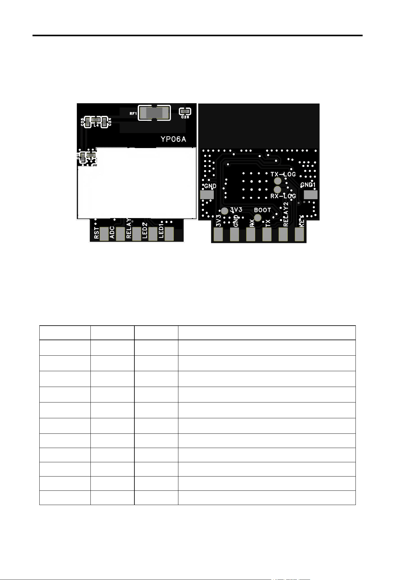
The YP06A module supports Zigbee 3.0 and BLE 5.0 protocols, featuring 132KB RAM,
192KB ROM, 1Kb eFuse, and a maximum clock frequency of 144MHz. Figure 1(a and b) below
shows the module schematic diagram.
a b
a b
graph 1
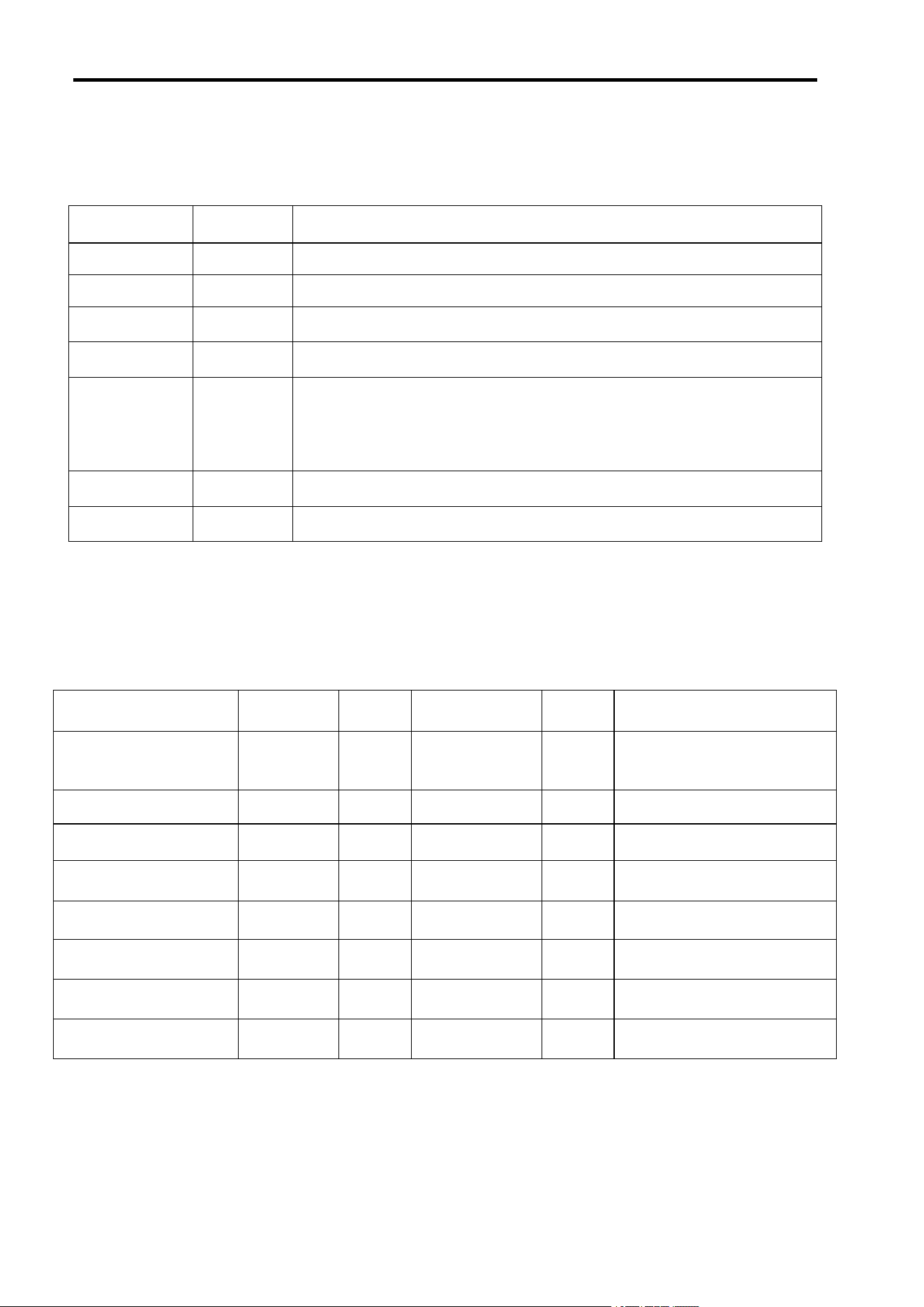
2. Interface Description
(1) PIN interface
The 11PIN pad interface specifications are detailed in Table 1 below:
Table 1
Module Pin
Pin name
IO type
description
1
3V3
P
Module power input, typical application: 3.3V supply
2
LED1
I/O
Main chip GPIO30, PWM0
3
GND
P
Module power ground
4
LED2
I/O
Main chip GPIO29, PWM4
5
RX
I/O
Main chip GPIO18, UART RX
6
RELAY1
I/O
Main chip GPIO22
7
TX
I/O
Main chip GPIO17, UART TX
8
9
ADC
I/O
Main chip GPIO21
9
RELAY2
I/O
Main chip GPIO20
10
RST
/
Main chip PU_CHIP pin, internally pull-up module, high-
level enable
11
KEY
I/O
Main chip GPIO19
Zhenjiang Youpu Technology Co., Ltd.
Copyright © 2023 Zhenjiang Youpu Technology Co., Ltd. All rights reserved
Page 5 of 8
(2) Test points
As shown in Figure 1(b), the test points on the back of the module are used for
product manufacturing testing and debugging purposes, as detailed in Table 2 below:
Table 2
order
number
Pin name
description
1
3V3
VDD, powered by a 3.3V module.
2
GND/GND1
GND, module power ground.
3
RX-LOG
The main chip's GPIO15 (RX) is dedicated to flashing and debugging
functions.
4
TX-LOG
The main chip's GPIO14 (TX) is dedicated to programming and debugging
functions.
5
BOOT
Main chip GPIO31 (Boot):
Upon power-on, the initial low-level signal initiates normal operation mode.
The initial high voltage from the power supply activates Flash programming
mode.
III. Key Parameters
See Table 3 below for the main parameters of the module.
Table 3
characteristic
parameter
least
value
representative
value
crest
value
test condition
supply voltage
VDD
2.7V
3.3V
3.5V
T=25
℃
The main chip is equipped with
built-in Flash memory, with a
voltage
≥
2.7V.
operating temperature
range
TOpr
-20°C
25°C
85°C
VDD=3.3V
Output voltage high
VOH
0.9VDD
VDD=3.3V,T=25℃
Output voltage low
VOL
0.1VDD
VDD=3.3V,T=25℃
Input voltage high
VIH
0.7VDD
VDD=3.3V,T=25℃
Input voltage low
VIL
0.3VDD
VDD=3.3V,T=25
℃
RF TX
mA
45
VDD=3.3V,T=25°C, 14dBm
RF RX
mA
3.5
Zhenjiang Youpu Technology Co., Ltd.
Copyright © 2023 Zhenjiang Youpu Technology Co., Ltd. All rights reserved
Page 5 of 8
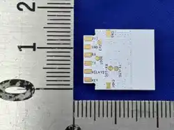
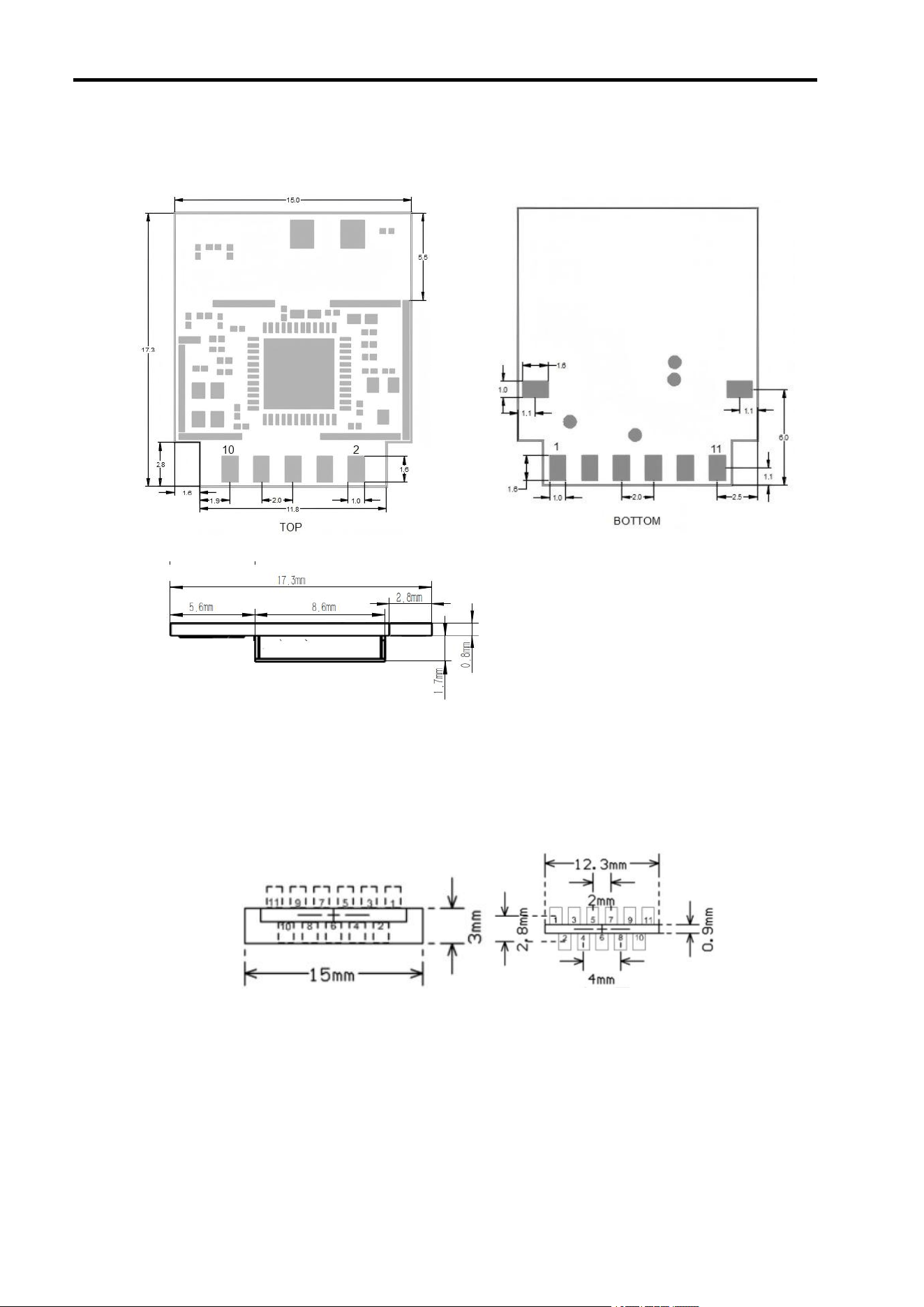
IV. Mechanical Dimensions
Refer to Figure 2 below for the module's mechanical dimensions.
graph 2
V. Packaging
Refer to Figure 3 below for details. PCB encapsulation is recommended.
(a) Double-sided PCB Top clearance zone (b) Double-sided PCB Bottom (mirror image) (a) Double-sided PCB Top clearance
zone (b) Double-sided PCB Bottom (mirror image)
graph 3

Zhenjiang Youpu Technology Co., Ltd.
Copyright © 2023 Zhenjiang Youpu Technology Co., Ltd. All rights reserved
Page 5 of 8
VI. Antenna
(1) Antenna type
The YP06A module is a surface-mount ceramic antenna.
(2) Antenna Description
To maximize the radiation performance of the antenna, the following recommendations are
advised:
① The spatial three-dimensional distance between the module antenna area and metal
components of user products (such as housing positioning screws, power supply wires, signal
conductors, hardware parts, etc.) must be at least 6–15 mm.
② The user's PCB board must not have traces or copper-clad layers in the 6mm area
directly beneath the module antenna region and its surroundings.
③ The module is positioned at one corner or side of the product, with the antenna area
facing outward toward the user.
7. Contact Us
Company website:
Business and Technical Support: 15996846172

Zhenjiang Youpu Technology Co., Ltd.
Copyright © 2023 Zhenjiang Youpu Technology Co., Ltd. All rights reserved Page 5 of 8
8.The others information
A: This device complies with part 15 of the FCC Rules. Operation is subject to the
following tw
FCC ID : 2BOSO-YP06A
IC ID : 33844-YP06A
HVIN : YP06A
FCC Statement
FCC standards: FCC CFR Title 47 Part 15 Subpart C Section 15.247
o
conditions: (1) This device may not cause harmful interference, and (2) this device must
accept any
interference received, including interference that may cause undesired operation.
B: Any Changes or modifications not expressly approved by the party responsible for
compliance could
void the user's authority to operate the equipment.
C: Note: This equipment has been tested and found to comply with the limits for a Class
B digital device,
pursuant to part 15 of the FCC Rules. These limits are designed to provide reasonable
protection against
harmful interference in a residential installation. This equipment generates, uses and can
radiate radio
frequency energy and, if not installed and used in accordance with the instructions, may
cause harmful
interference to radio communications. However, there is no guarantee that interference
will not occur in a
particular installation. If this equipment does cause harmful interference to radio or
television reception,
which can be determined by turning the equipment off and on, the user is encouraged to
try to correct the
interference by one or more of the following measures:
—Reorient or relocate the receiving antenna.
—
Increase the separation between the equipment and receiver.
— Connect the equipment into an outlet on a circuit different from that to which the
receiver is connected.
—Consult the dealer or an experienced radio/TV technician for help.
FCC Radiation Exposure Statement
The modular can be installed or integrated in mobile or fix devices . This modular cannot
be installed in any

Zhenjiang Youpu Technology Co., Ltd.
Copyright © 2023 Zhenjiang Youpu Technology Co., Ltd. All rights reserved
Page 5 of 8
portable device if without further certification such as C2PC with SAR. This modular
complies with FCC
RF radiation exposure limits set forth for an uncontrolled environment. This transmitter
must not be
co-located or operating in conjunction with any other antenna or transmitter. This
modular must be installed
and operated with a minimum distance of 20 cm between the radiator and user body.
If the FCC identification number is not visible when the module is installed inside another
device, then the
outside of the device into which the module is installed must also display a label referring
to the enclosed
module. This exterior label can use wording such as the following: “Contains Transmitter
Module FCC ID:
2BOSO-YP06A Or Contains FCC ID: 2BOSO-YP06A”
The devices must be installed and used in strict accordance with the manufacturer's
instructions as described
in the user documentation that comes with the product.
Any company of the host device which install this modular with modular approval should
perform the test of
radiated & conducted emission and spurious emission,etc. according to FCC part15B
Class B requirement,
Only if the test result comply with FCC part 15B Class B requirement,then the host can
be sold legally.
When the module is installed inside another device, the user manual of the host must
contain above
Paragraphs A, B, and C warning statements.IC STATEMENT
A: This device contains licence-exempt transmitter(s)/receiver(s) that comply with
Innovation,
Science and Economic Development Canada’s licence-exempt RSS(s). Operation is
subject
to the following two conditions:
(1) This device may not cause interference.
(2) This device must accept any interference, including interference that may cause
undesired operation of the device
B: Cet appareil contient des émetteurs / récepteurs exemptés de licence conformes aux
RSS (RSS)
d'Innovation, Sciences et Développement économique Canada. Le fonctionnement est
soumis aux
deux conditions suivantes :
(1) Cet appareil ne doit pas causer d'interférences.
(2) Cet appareil doit accepter toutes les interférences, y compris celles susceptibles de

Zhenjiang Youpu Technology Co., Ltd.
Copyright © 2023 Zhenjiang Youpu Technology Co., Ltd. All rights reserved
Page 5 of 8
provoquer un fonctionnement indésirable de l'appareil.
IC Radiation Exposure Statement
This modular complies with IC RF radiation exposure limits set forth for an uncontrolled
environment. This transmitter must not be co-located or operating in conjunction with any
other
antenna or transmitter. This modular must be installed and operated with a minimum
distance of 20
cm between the radiator and user body. Cette modulaire doit être installé et utilisé à une
distance
minimum de 20 cm entre le radiateur et le corps de l'utilisateur.
If the IC number is not visible when the module is installed inside another device, then
the outside
of the device into which the module is installed must also display a label referring to the
enclosed
module. This exterior label can use wording such as the following:
“Contains IC: 33844-YP06A
”
when the module is installed inside another device, the user manual of this device must
contain
Above paragraph A&B warning statements .
The devices must be installed and used in strict accordance with the manufacturer's
instructions as
described in the user documentation that comes with the product