Terminal Function
L, N 230 V AC power supply
Earth
COM, NO Volt-free output, normally open contacts
Switch LED diode Description
Auto
/ Manual
Blinks in red
Receiver is powered 230 V
and is prepared for pairing with
the ZigBee network
Solid red
Receiver is powered 230 V
and is connected to the ZigBee network
On / O
Solid green
The heating device is turned ON
O
The heating device is turned OFF
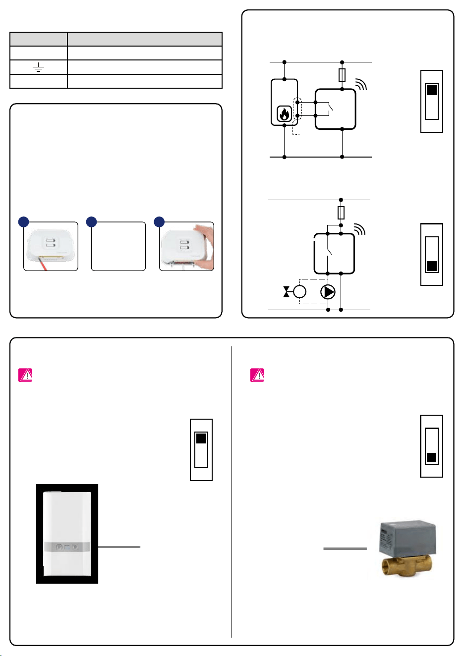
Installation
Terminals description
Wiring diagrams
Switches and LED diodes description
Module conguration in RX1 mode (default option) Module conguration in RX2 mode
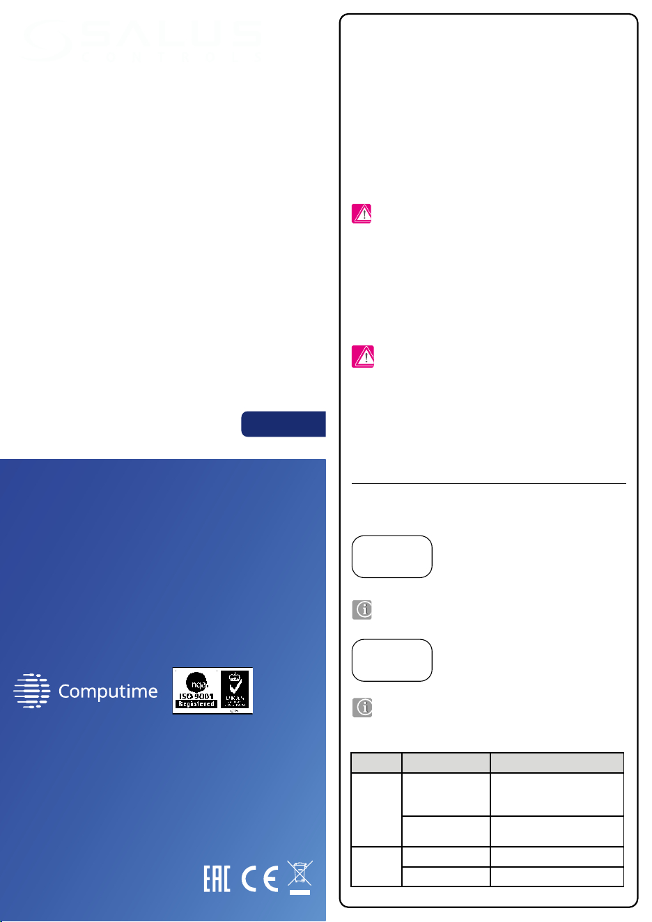
Introduction
Product Compliance
Safety Information
The RX10RF control module is an external element in the SALUS Smart Home
system which turns ON when a heating signal is received from thermostats
in the same network. It can replace a wired connection between the KL08RF
wiring centre and the boiler. In a system with TRV heads it is a optional device
that activates the heat source. For the RX10RF to work together with wireless
SALUS Smart Home series thermostats, it must be used with a CO10RF coordinator
(in Oine mode) or internet gateway UGE600 (in Online mode) and the SALUS
Smart Home application. This module can work as a receiver:
• of all thermostats (RX1 mode) - reacts to any heating command from all
SALUS Smart Home thermostats in the ZigBee network
• of one thermostat (RX2 mode) - reacts to the heating command from one
SALUS Smart Home thermostat in the ZigBee network
The RX10RF receiver should be mounted in a place where 230 V power supply
is available and wireless connectivity can not be disrupted.
The receiver’s power supply should be protected by a fuse (max 16 A). The
receiver’s installation place should not be exposed to moisture. There are
several options for connecting the receiver to the heating device. All wires
should be connected inside the receiver’s housing, to the proper inputs. The
ground connection is not necessary for the correct receiver operation, but it is
recommended, if it is possible.
Receiver congured in the RX1 mode
(wireless boiler control module)
BOILER TERMINALS TO
CONNECT ON/OFF TYPE
THERMOSTAT (ACCORDING
TO BOILER INSTRUCTION)
Receiver congured in the RX2 mode
(individual control for separate heating zone)
or
Use in accordance to national and EU regulations. Use the device as intended,
keeping it in dry condition. Product for indoor use only. Installation must be
carried out by a qualied person in accordance to national and EU regulations.
The device must remain disconnected from power supply before removing the
housing. In emergency situation disconnect a single component or the entire
SALUS Smart Home system from the power supply. During installation, the device
must be disconnected from the 230 V power supply!
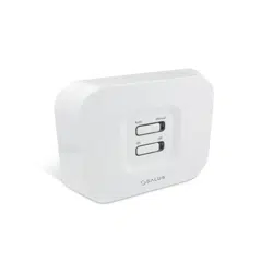
AUTO MODE - When the top switch of RX10RF
receiver is set to AUTO, it means that the heating
device will be switched ON/OFF in accordance to
the request of a transmitter (thermostat).
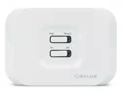
MANUAL MODE - When the top switch is set
to MANUAL, it means that the heating device
is switched ON/OFF manually by the bottom
ON/OFF switch.
Inside the module there is a switch selector for operating
mode. The RX1 position means that the module responds to
a heating signal from any SALUS Smart Home thermostat in
the ZigBee network (from many heating zones).
Module congured in RX1 mode - will NOT turn ON the
other RX10RF receiver (congured in mode RX2) in the same
network.
Inside the module there is a switch selector for operating
mode. The RX2 position means that the module responds to
a heating signal only from one SALUS Smart Home thermostat
in the ZigBee network (from one heating zone).
The SALUS Smart Home series thermostat have to be congured
during installation to work with the module in RX2 mode. (More
information is in the user manual of the SALUS Smart Home
series thermostat).
Module congured in RX2 mode - will turn ON the other RX10RF
receiver (congured in RX1 mode) in the same network.
Receiver congured in the RX1 mode - as a remote boiler control module.
Receiver is connected to the boiler according to the proper wiring diagram.
Receiver congured in the RX2 system - for individual control heating zone.
Receiver is connected to the valve/pump according to the proper wiring diagram.
Directives: Electromagnetic Compatibility EMC 2014/30/EU, Low Voltage
Directive LVD 2014/35/EU, Radio Equipment Directive RED 2014/53/EU
and RoHS 2011/65/EU. Full information is available on the website
www.saluslegal.com
RX1
RX1
RX2
RX2
L
L
RX10RF
230 V AC
NO
N
N
COM
CCOMOMCOM
230 V AC
L
L
RX10RF
M
N
N
NO
Note: With one ZigBee network coordinator (CO10RF or UGE600)
only two modules can be used, one in RX1 mode and one in RX2
mode.
Note: Before opening the case, disconnect the device from
the power supply 230V~.
Note: Before opening the case, disconnect the device from
the power supply 230V~.
Loosen the screws from
the receiver bottom housing,
then open the housing.
Mount the back housing of the
receiver, and then connect wires
according to the appropriate
schematic for your heating device.
Remount the front housing.
Tighten the screws located
on the bottom of the
housing receiver.
1 2 3
RX1
RX2
RX1
RX2
ZigBee network control module
Model: RX10RF
PRODUCER:
SALUS Controls Plc Units 8-10 Northfield
Business Park Forge Way, Parkgate,
Rotherham S60 1SD, United Kingdom
www.saluscontrols.com
SALUS Controls is a member of the Computime Group.
Maintaining a policy of continuous product development SALUS Controls
plc reserve
the right to change specification, design and materials
of products listed in this brochure without prior notice.
Manual
[EN] V 2020
The bottom slider ON/OFF is inactive in automatic mode.
In a case of a communication failure or a transmitter malfunction,
you can use manual mode to control the heating device until
the problem is solved.
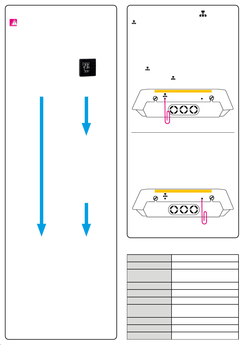
Terminal Function
L, N 230 V AC power supply
Earth
COM, NO Volt-free output, normally open contacts
Switch LED diode Description
Auto
/ Manual
Blinks in red
Receiver is powered 230 V
and is prepared for pairing with
the ZigBee network
Solid red
Receiver is powered 230 V
and is connected to the ZigBee network
On / O
Solid green
The heating device is turned ON
O
The heating device is turned OFF
Installation
Terminals description
Wiring diagrams
Switches and LED diodes description
Module conguration in RX1 mode (default option) Module conguration in RX2 mode
Introduction
Product Compliance
Safety Information
The RX10RF control module is an external element in the SALUS Smart Home
system which turns ON when a heating signal is received from thermostats
in the same network. It can replace a wired connection between the KL08RF
wiring centre and the boiler. In a system with TRV heads it is a optional device
that activates the heat source. For the RX10RF to work together with wireless
SALUS Smart Home series thermostats, it must be used with a CO10RF coordinator
(in Oine mode) or internet gateway UGE600 (in Online mode) and the SALUS
Smart Home application. This module can work as a receiver:
• of all thermostats (RX1 mode) - reacts to any heating command from all
SALUS Smart Home thermostats in the ZigBee network
• of one thermostat (RX2 mode) - reacts to the heating command from one
SALUS Smart Home thermostat in the ZigBee network
The RX10RF receiver should be mounted in a place where 230 V power supply
is available and wireless connectivity can not be disrupted.
The receiver’s power supply should be protected by a fuse (max 16 A). The
receiver’s installation place should not be exposed to moisture. There are
several options for connecting the receiver to the heating device. All wires
should be connected inside the receiver’s housing, to the proper inputs. The
ground connection is not necessary for the correct receiver operation, but it is
recommended, if it is possible.
Receiver congured in the RX1 mode
(wireless boiler control module)
BOILER TERMINALS TO
CONNECT ON/OFF TYPE
THERMOSTAT (ACCORDING
TO BOILER INSTRUCTION)
Receiver congured in the RX2 mode
(individual control for separate heating zone)
or
Use in accordance to national and EU regulations. Use the device as intended,
keeping it in dry condition. Product for indoor use only. Installation must be
carried out by a qualied person in accordance to national and EU regulations.
The device must remain disconnected from power supply before removing the
housing. In emergency situation disconnect a single component or the entire
SALUS Smart Home system from the power supply. During installation, the device
must be disconnected from the 230 V power supply!
AUTO MODE - When the top switch of RX10RF
receiver is set to AUTO, it means that the heating
device will be switched ON/OFF in accordance to
the request of a transmitter (thermostat).
MANUAL MODE - When the top switch is set
to MANUAL, it means that the heating device
is switched ON/OFF manually by the bottom
ON/OFF switch.
Inside the module there is a switch selector for operating
mode. The RX1 position means that the module responds to
a heating signal from any SALUS Smart Home thermostat in
the ZigBee network (from many heating zones).
Module congured in RX1 mode - will NOT turn ON the
other RX10RF receiver (congured in mode RX2) in the same
network.
Inside the module there is a switch selector for operating
mode. The RX2 position means that the module responds to
a heating signal only from one SALUS Smart Home thermostat
in the ZigBee network (from one heating zone).
The SALUS Smart Home series thermostat have to be congured
during installation to work with the module in RX2 mode. (More
information is in the user manual of the SALUS Smart Home
series thermostat).
Module congured in RX2 mode - will turn ON the other RX10RF
receiver (congured in RX1 mode) in the same network.
Receiver congured in the RX1 mode - as a remote boiler control module.
Receiver is connected to the boiler according to the proper wiring diagram.
Receiver congured in the RX2 system - for individual control heating zone.
Receiver is connected to the valve/pump according to the proper wiring diagram.
Directives: Electromagnetic Compatibility EMC 2014/30/EU, Low Voltage
Directive LVD 2014/35/EU, Radio Equipment Directive RED 2014/53/EU
and RoHS 2011/65/EU. Full information is available on the website
www.saluslegal.com
RX1
RX1
RX2
RX2
L
L
RX10RF
230 V AC
NO
N
N
COM
CCOMOMCOM
230 V AC
L
L
RX10RF
M
N
N
NO
Note: With one ZigBee network coordinator (CO10RF or UGE600)
only two modules can be used, one in RX1 mode and one in RX2
mode.
Note: Before opening the case, disconnect the device from
the power supply 230V~.
Note: Before opening the case, disconnect the device from
the power supply 230V~.
Loosen the screws from
the receiver bottom housing,
then open the housing.
Mount the back housing of the
receiver, and then connect wires
according to the appropriate
schematic for your heating device.
Remount the front housing.
Tighten the screws located
on the bottom of the
housing receiver.
1 2 3
RX1
RX2
RX1
RX2
ZigBee network control module
Model: RX10RF
PRODUCER:
SALUS Controls Plc Units 8-10 Northfield
Business Park Forge Way, Parkgate,
Rotherham S60 1SD, United Kingdom
www.saluscontrols.com
SALUS Controls is a member of the Computime Group.
Maintaining a policy of continuous product development SALUS Controls
plc reserve
the right to change specification, design and materials
of products listed in this brochure without prior notice.
Manual
[EN] V 2020
The bottom slider ON/OFF is inactive in automatic mode.
In a case of a communication failure or a transmitter malfunction,
you can use manual mode to control the heating device until
the problem is solved.
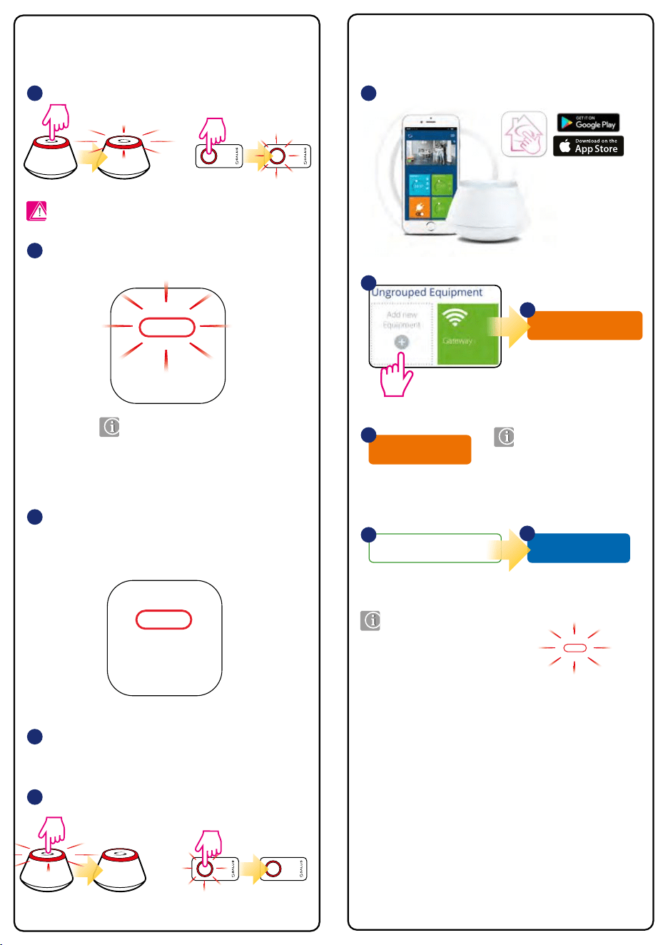
Connect equipment
OR
5 sec
5 sec
Pairing in local mode (Oine) Pairing via application (Online) Two modules in one ZigBee network
PAIR / IDENTIFICATION button
RESET button
Technical data
Open the ZigBee network.
(with UGE600 gateway and Internet connection)
(with UGE600 gateway or CO10RF coordinator, without Internet connection)
Just connect the receiver to the power supply and set the bottom
switch to ON position - the red LED will start ashing.
To pair other SALUS Smart Home devices - read the appropriate
model’s manual instructions.
Close the ZigBee network.
When the pairing process of the receiver is successful, the red LED
light will stop ashing. RX10RF pairing with the ZigBee network is
automatic, it is not necessary to press any additional buttons.
Any of thermostat can turn ON
RX10RF module congured
in RX1 mode.
START RX1
Just one thermostat can turn ON
RX10RF module congured
in RX2 mode...
START RX2
RX1
1 1
4
2
4
5
3
5 sec
5 sec
OR
Note: Do not use the CO10RF coordinator with UGE600 gateway!
Note: Two RX10RF modules (receivers) can be paired with one
UGE600 gateway:
• rst in RX1 mode
• second in RX2 mode
Reset
WARNING! ISOLATE MAINS SUPPLY PRIOR TO OPENING UNIT.
Reset
WARNING! ISOLATE MAINS SUPPLY PRIOR TO OPENING UNIT.
Reset
WARNING! ISOLATE MAINS SUPPLY PRIOR TO OPENING UNIT.
button is used for pairing/removing the module, as well as for identication
in the ZigBee network.
If the module is paired with ZigBee network, holding the pairing button for
5 seconds will remove the device from the network. When the device is removed
from the ZigBee network the red LED light will blink two times every 1 second.
To add the module to the network again, press the RESET button to refresh the
module.
To check whether the device is in the ZigBee network (identication mode), please
press the button for 1 sec. the green LED light on the receiver and lights on
the CO10RF coordinator or UGE600 Internet gateway will start to ash. To exit the
identication mode, press the button again.
At the bottom of the RX10RF there is a RESET button. Use it to refresh
the module.
If for some reason the RX10RF module does not work properly, press
the RESET button as shown on the picture below, then disconnect the
module from power supply for few minutes.
Reset
WARNING! ISOLATE MAINS SUPPLY PRIOR TO OPENING UNIT.
Model RX10RF
Power supply 230 V AC 50 Hz
Type
RX10RF is designed to work with
the SALUS Smart Home system
Type of control ON/OFF
Operation temperature 0°C to + 50°C
Storage temperature -20°C to + 60°C
Maximum allowable
humidity
5-95% RH (not condensed)
Max load 16 (5) A
Communication ZigBee 2.4 GHz
Dimensions [mm] 145 x 100 x 35
SALUS Smart Home
Name this equipment
RX10RF
5
If the system does not detect
module, press the „RESET”
button in order to „refresh”
module.
If the system does not want
to detect module, press the
„RESET” button in order to
„refresh” module.
When the pairing process
of the receiver is successful,
the RX10RF module will
appear in the application
and the light on the module
will stop ashing.
Finish
6
...when the RX10RF (congured
as RX2) is turned ON,
then the RX10RF (congured
as RX1) will turn ON too.
Reset
WARNING! ISOLATE MAINS SUPPLY PRIOR TO OPENING UNIT.
Reset
WARNING! ISOLATE MAINS SUPPLY PRIOR TO OPENING UNIT.
RX2
2
Scan for equipment
3