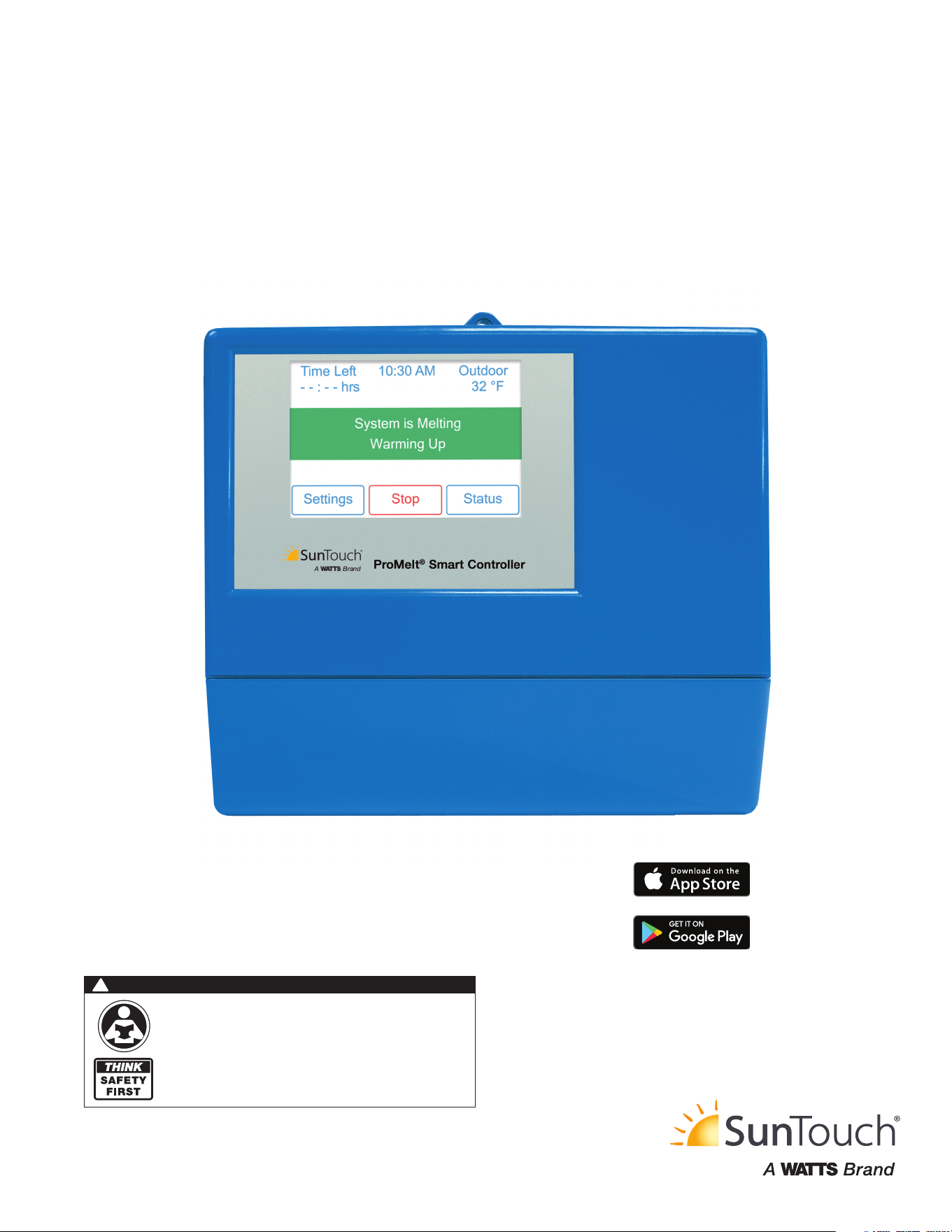
Installation, Operation and Maintenance
ProMelt
®
Smart Controller
IOM-ST-ProMeltSmartController
WARNING
!
Please read carefully before proceeding with
installation. Your failure to follow any attached
instructions or operating parameters may lead to the
product’s failure.
Keep this Manual for future reference.

2
Contents
Getting Started …………………………………………………… 2
Important Safety Information …………………………………… 3
Radio Frequency Interference …………………………………… 3
Installation ………………………………………………………… 4
Preparation ………………………………………………………… 4
Physical Dimensions ……………………………………………… 4
Installation Location ……………………………………………… 4
Packaging Contents ……………………………………………… 4
Installing the Enclosure …………………………………………… 5
Rough-In Wiring …………………………………………………… 6
Sensor Wiring …………………………………………………… 7
tekmarNet ………………………………………………………… 9
Manual Melt Input ………………………………………………… 9
Equipment Wiring ……………………………………………… 10
ContactorPro …………………………………………………… 10
Testing the Sensor Wiring ……………………………………… 11
Testing the Control Wiring …………………………………… 11
Manual Override – Maximum Heat …………………………… 12
Manual Override – Purge ……………………………………… 12
Manual Override – Off ………………………………………… 12
Access Levels ………………………………………………… 12
User Interface …………………………………………………… 13
Home Screen …………………………………………………… 13
Symbols ………………………………………………………… 14
Help Screen …………………………………………………… 14
Status Menu Navigation ……………………………………… 14
System Status Menu …………………………………………… 15
Slab Status Screen …………………………………………… 15
Weather Status Screen ………………………………………… 16
Settings Menu Navigation……………………………………… 16
Temp Menu …………………………………………………… 18
Away Menu …………………………………………………… 19
Display Menu …………………………………………………… 19
WiFi Menu ……………………………………………………… 20
Time Menu ……………………………………………………… 20
Energy Menu …………………………………………………… 21
Monitor Menu …………………………………………………… 21
Setup – System Setup Menu ………………………………… 22
Setup – Boiler Setup Menu …………………………………… 22
Congratulations on the purchase of your new Snow Melting Control!
This manual covers the complete installation, programming and
sequence of operation for this control. You will also find instruction
on testing, commissioning, and troubleshooting the control and sys-
tem that it operates.
Getting Started
tekmarNet Menu ……………………………………………… 23
Toolbox Menu ………………………………………………… 24
Override Menu ………………………………………………… 24
Watts
®
Home App ……………………………………………… 25
Sequence of Operation ………………………………………… 26
Snow Melting Overview ……………………………………… 26
Melt – Automatic Start and Stop ……………………………… 26
Melt – EconoMelt ……………………………………………… 27
Additional Melting Time ……………………………………… 27
Melt – Automatic Start and Timed Stop ……………………… 27
Tandem Snow/Ice Detection ………………………………… 28
Melt – Manual Start and Timed Stop ………………………… 28
Melt - Tracked Start and Stop ………………………………… 28
Idle Operation ………………………………………………… 29
Storm Operation ……………………………………………… 29
Slab Temperature Control ……………………………………… 30
Snow Melt Zones and Priority ………………………………… 30
Warm Weather Shut Down …………………………………… 32
Cold Weather Cut Off ………………………………………… 32
Time Clock ……………………………………………………… 32
Away Operation ………………………………………………… 32
tekmarNet Scene Operation ………………………………… 32
Pulse Width Modulation Zone Operation …………………… 33
Outdoor Sensor ………………………………………………… 33
Exercising ……………………………………………………… 33
Post Purge ……………………………………………………… 33
Troubleshooting ………………………………………………… 34
Error Messages (1 of 2) ………………………………………… 34
Error Messages (2 of 2) ………………………………………… 35
Frequently Asked Questions ………………………………… 36
Technical Data ………………………………………………… 39
Limited Warranty and Product Return Procedure …………… 40
3
The installer must ensure that this control and its wiring are
isolated and/or shielded from strong sources of electromag-
netic noise. Conversely, this Class B digital apparatus complies
with Part 15 of the FCC Rules and meets all requirements of
the Canadian Interference-Causing Equipment Regulations.
However, if this control does cause harmful interference to
radio or television reception, which is determined by turning the
control off and on, the user is encouraged to try to correct the
interference by re-orientating or relocating the receiving antenna,
relocating the receiver with respect to this control, and/or con-
necting the control to a different circuit from that to which the
receiver is connected.
Important Safety Information
It is your responsibility to ensure that this control is safely installed
according to all applicable codes and standards.
Watts is not responsible for damages resulting from improper
installation and/or maintenance.
This is a safety-alert symbol. The safety alert
symbol is shown alone or used with a signal
word (DANGER, WARNING, or CAUTION), a
pictorial and/or a safety message to identify haz-
ards. When you see this symbol alone or with a
signal word on your equipment or in this manual,
be alert to the potential for death or serious
personal injury.
This pictorial alerts you to electricity, electrocution,
and shock hazards.
This symbol identifies hazards which, if not avoided, could result
in death or serious injury.
This symbol identifies hazards which, if not avoided, could result
in minor or moderate injury.
This symbol identifies practices, actions, or failure to act which
could result in property damage or damage to the equipment.
Read manual and all product labels
BEFORE using the equipment.
Do not use unless you know the
safe and proper operation of this
equipment. Keep this manual
available for easy access by all
users. Replacement manuals are
available at tekmarControls.com
• It is the installer’s responsibility to ensure that this control
is safely installed according to all applicable codes and
standards.
• Improper installation and operation of this control could
result in damage to the equipment and possibly even
personal injury or death.
• This control is not intended for use as a primary limit
control. Other controls that are intended and certified as
safety limits must be placed into the control circuit.
Radio Frequency Interference
Do not attempt to service the control. There are no user
serviceable parts inside the control. Attempting to service the
control voids the warranty.
NOTICE
4
Tools Required
• Screwdriver
• Phillips head screwdriver
• Needle-nose pliers
• Wire stripper
Materials Required
• 18 AWG LVT solid wire (low-voltage connections)
• 14 AWG solid wire (line-voltage connections)
• Four
1
⁄8" - 1" wood screws
Installation
Choose the placement of the control early in the construction process to enable proper wiring during rough-in.
The following are included in the product packaging:
• 1 ProMelt
®
Smart Controller
• 1 Outdoor Sensor 070
• 1 screwdriver
• 1 Installation and Operation Manual PSC
Preparation
Packaging Contents
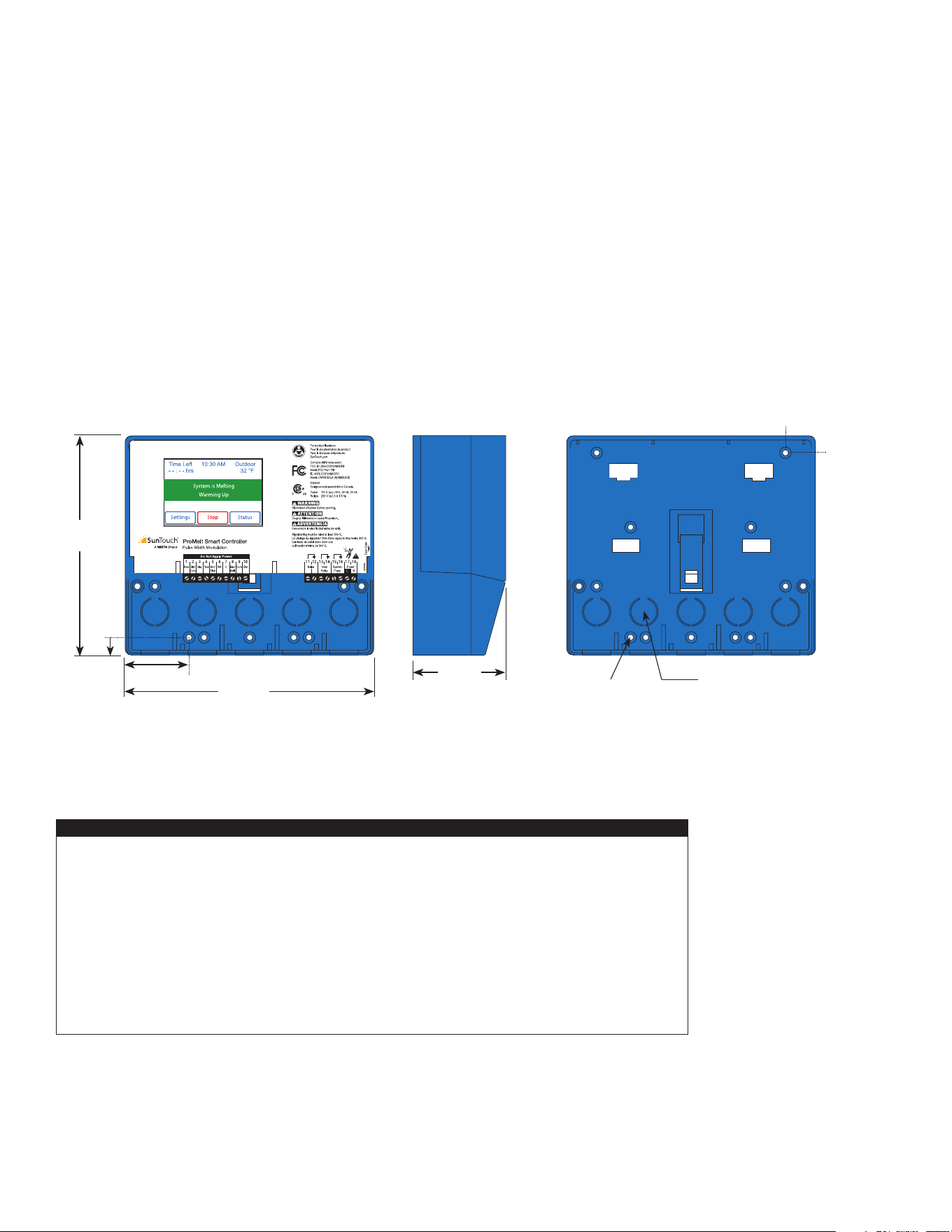
Front View
Side View
2
7
⁄8"
(72 mm)
½" Knock-out
(x 5 back) (x 5 bottom)
Mounting Base
CL
½"
(13 mm)
7
⁄8"
(23 mm)
6
5
⁄8"
(170 mm)
7
5
⁄8"
(193 mm)
1
7
⁄8"
(49 mm)
1
/2"
(14 mm)
3
⁄16" (5 mm)
Physical Dimensions
Installation Location
• Keep the control dry. Avoid potential leakage onto the control.
• Maintain relative humidity less than 90% in a non-condensing environment.
• Avoid exposure to extreme temperatures beyond 32-122°F (0-50°C).
• Install away from equipment, appliances, or other sources of electrical interference.
• Install to allow easy access for wiring, viewing, and adjusting the display screen.
• Install approximately 5 feet (1.5 m) off the finished floor.
• Locate the control near pumps and/or zone valves if possible.
• Provide a solid backing which the enclosure can be mounted to. Example: plywood or wall studs.
• Use the conduit knockouts provided on the upper, lower, back and sides of the enclosure for wiring.
NOTICE
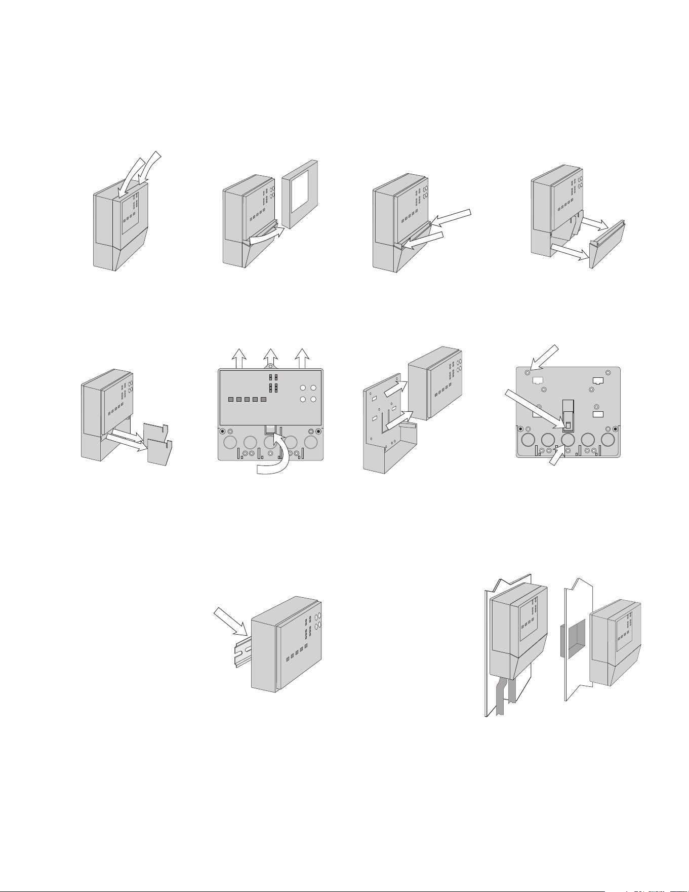
5
• Install the control enclosure to a wall or to an electrical box.
• Three wiring chamber dividers are included. The dividers provide a barrier to keep low voltage
wiring separated from line voltage wiring.
• If the dividers are not used, then low voltage circuits must use wire rated at least 300 V.
Press down at the fingertip
grips on top of the front cover
and pull out and down.
Lift the front cover up and
away
from the control.
Loosen the screws at the
front of the wiring cover.
The wiring cover pulls straight
out from the wiring chamber.
The base is ready for mounting.The control lifts up and away
from the base.
Press the control release
clip on the base inside the
wiring chamber and slide
the control upwards.
Remove the safety dividers
from the wiring chamber by
pulling them straight out of
their grooves.
There are 10 conduit knock-outs at the
back and bottom of the wiring chamber.
13 Mounting holes
Control
release
clip
Control
release clip
The control can be mounted on
a standard DIN rail. First remove
the control from its base and then,
using the hooks and spring clip
on the back of the control, mount
it onto the DIN rail. This will be a
popular option for those who prefer
to mount the control inside a larger
electrical panel. The DIN Snap Kit
M9303 is sold separately.
The wiring can enter the
bottom or the back of the
enclosure. Knock-outs pro-
vided in the base allow the
wiring to be run in conduit
up to the enclosure. The
base also has holes that
line up with the mounting
holes of most common
electrical boxes.
Installing the Enclosure
6
Pull two conductor 18 AWG LVT cable, up to 500 feet
(150 m) long, for the following equipment:
• Outdoor temperature sensor
• Boiler sensor
• Single-stage on/off boiler
Pull four conductor 18 AWG LVT cable, up to 500 feet
(150 m) long, for the following equipment:
• Snow Sensor 095
Pull the Snow/Ice Sensor 090 or 094 cable to the control.
Pull five conductor 18 AWG LVT cable, up to 500 feet
(150 m) long, for the following equipment:
• Snow/Ice Sensor 090
Pull two conductor 14 AWG cable, up to 500 feet
(150 m) long, for the following equipment:
• System pump
• Boiler pump
Rough-In Wiring
To prevent the risk of personal injury and/or
death, make sure power is not applied to the
control until it is fully installed and ready for final
testing. All work must be done with power to the
circuit being worked on turned off.
Please be aware local codes may require this
control to be installed or connected by an
electrician.
Low-Voltage Wiring
Line-Voltage Wiring
• Install the supplied wiring compartment barriers by sliding
them into the grooves provided to isolate the low and
line-voltage wiring.
• Strip all wiring to a length of
3
⁄8 in. or 10 mm for all
terminals.
• A circuit breaker or power disconnect that provides power
to the control should be located nearby and clearly labeled.
• Refer to the current and voltage ratings at the back of this
manual before connecting devices to this control.
NOTICE
7
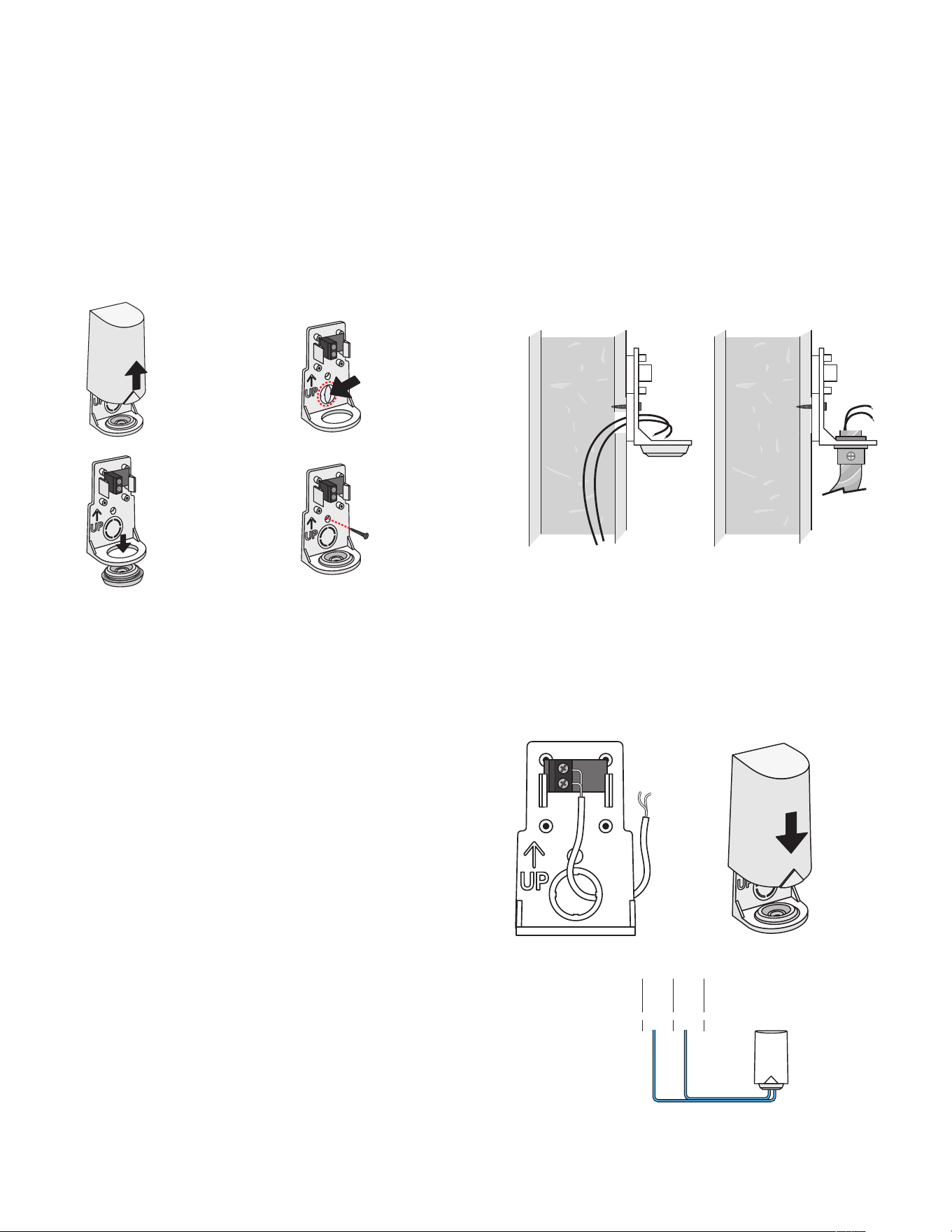
• The temperature sensor (thermistor) is built into the sensor
enclosure.
• The outdoor sensor can either be mounted directly onto a
wall and the wiring should enter through the back or bottom
of the enclosure. Do not mount the outdoor sensor with the
conduit knockout facing upwards because rain could enter
the enclosure and damage the sensor.
• In order to prevent heat transmitted through the wall from
affecting the sensor reading, it may be necessary to install an
insulating barrier behind the enclosure.
• The outdoor sensor should be mounted on a north-facing
wall. The outdoor sensor should not be exposed to heat
sources such as ventilation or window openings.
• The outdoor sensor should be installed at an elevation above
the ground that will prevent accidental damage or tampering.
Mounting the Outdoor Sensor
• Connect 18 AWG or similar wire to the two terminals provided
in the enclosure and run the wires from the outdoor sensor to
the control. Do not run the wires parallel to telephone or power
cables. If the sensor wires are located in an area with strong
sources of electromagnetic interference (EMI), shielded cable
or twisted pair should be used or the wires can be run in a
grounded metal conduit. If using shielded cable, the shield wire
should be connected to the Com terminal on the control and
not to earth ground.
• Follow the sensor testing instructions in this manual and con-
nect the wires to the control.
• Replace the front cover of the sensor enclosure.
Wiring the Outdoor Sensor
Remove cover
by sliding
upwards away
from the base.
To wire from the
back, remove the
knock-out in the
sensor base.
S1
S1
If using
conduit,
remove the
flexible plug
from the base
bottom.
S1
S1
Attach the
base to the
wall, soffit or
electrical box.
S1
S1
Wires from outdoor
sensor to control’s
outdoor sensor and
sensor common
terminals
Sensor is built into
the enclosure
Wires from out-
door sensor and
sensor common
terminals on
Watts control
S1
S1
At the control:
• Connect the outdoor sensor to terminals 9 and 10.
Com
9
Out
10
Com
9
Out
10
Sensor Wiring
8
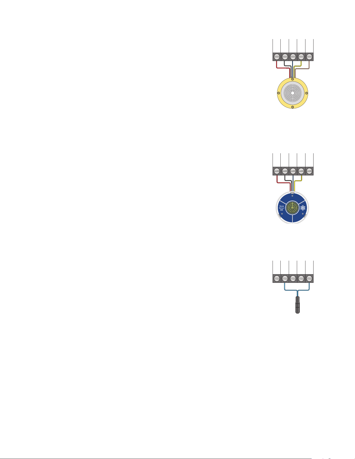
Snow / Ice Sensor
Snow Sensor
Slab Sensor
A Snow/Ice Sensor 090 or 094 can be connected to the control. The 090 has a 65'
(20 m) cable and the 094 has a 208' (63 m) cable. The cable may be extended to a
total length of 500' (150 m) using 18 AWG cable. Any junction boxes must kept dry.
If the Snow/Ice Sensor input is used:
• Connect the red wire to terminal 1.
• Connect the black wire to terminal 2.
• Connect the blue wire to terminal 3.
• Connect the yellow wire to terminal 4.
• Connect the brown wire to terminal 5.
A Snow Sensor 095 can be connected to the control.
If the Snow Sensor input is used:
• Connect the red wire to terminal 1.
• Connect the black wire to terminal 2.
• Connect the blue wire to terminal 3.
• Connect the yellow wire to terminal 4.
A Slab Sensor 072 or 073 can be installed either alone or together with a
Snow Sensor 095.
If the Slab Sensor input is used:
Connect the slab sensor to terminals 2 and 5.
Blu
3
Yel
4
Brn/
5
Slab
Blk/
2
Com
Red
1
Blu
3
Yel
4
Brn/
5
Slab
Blk/
2
Com
Red
1
Blu
3
Yel
4
Brn/
5
Slab
Blk/
2
Com
Red
1
9
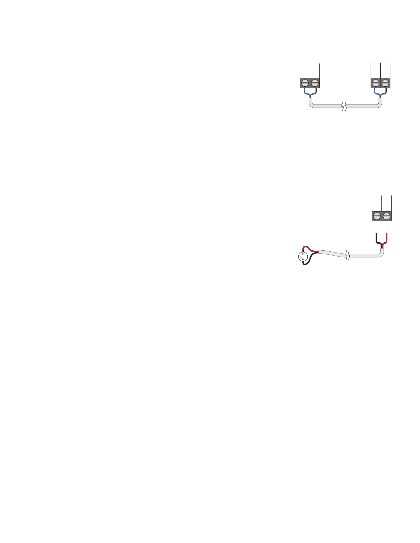
The ProMelt Smart Controller can be connected to other tekmarNet communication
compatible controls using the tN4 bus.
If tekmarNet is used:
• Connect tN4 on the ProMelt Smart Controller terminal 6 to the tN4 wiring terminal
on the other device.
• Connect C on the ProMelt Smart Controller terminal 7 to the C wiring terminal on
the other device.
• tekmarNet is polarity sensitive.
other tN4
control
ProMelt Smart Controller
6
C
7
tN4
C
tN4
The manual melt input allows the control to be manually switched to melting operation
using a switch. This connection is optional.
If the Manual Melt input is used:
Connect a switch to terminals 8 and 9. The switch may be either dry (no voltage) or a
voltage signal up to 32 V (ac).
Man
Melt
Com
9 8
tekmarNet
Manual Melt Input
10
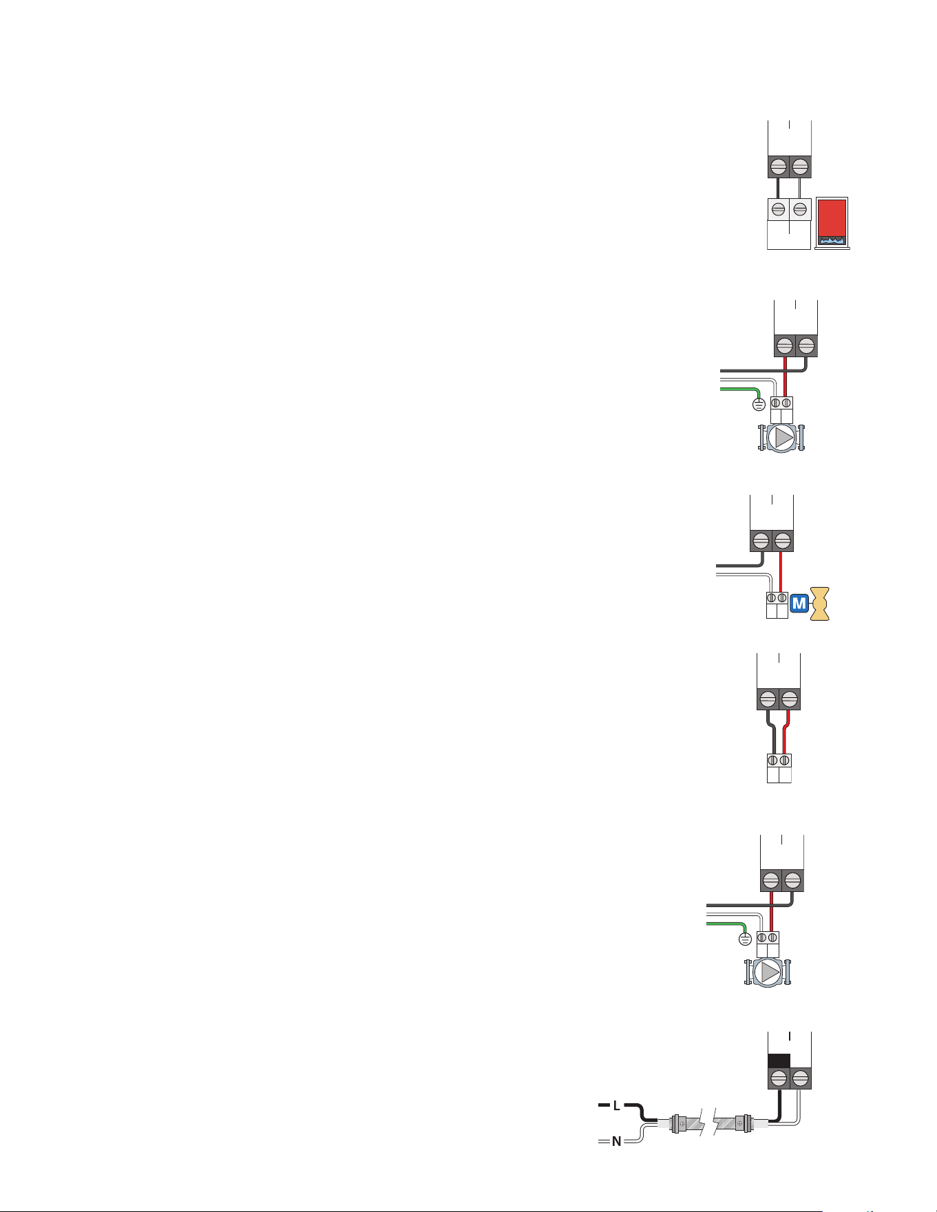
Wiring to a Single-Stage Boiler
A single-stage boiler is enabled through the T-T contacts.
• Connect Boiler terminals 11 and 12 to the boiler T-T contacts.
Stage 1
TT
Boiler
11 12
WR
Provide a 15 A circuit for the input power.
• Connect the 115 V (ac) line wire (L) to terminal 17.
• Connect the neutral wire (N) to terminal 18.
Power
17
L
18
N
Wiring the Input Power
If the heat relay is operating a pump:
The pump can be rated up to 230 V (ac), 5 A,
1
⁄3 hp and switched through
terminals 13 and 14. For simplicity in wiring and troubleshooting, a separate
breaker for each pump is recommended.
• Connect the power source line wire (L) to terminal 14.
• Connect a wire from terminal 13 to the pump L.
• Connect a wire from the pump N back to the power source neutral.
• Connect the ground wire (G) to the pump.
If the heat relay is wired to an electrical contactor (or ContactorPro):
• Connect a wire from terminal 13 to the electrical contactor R (24VAC on ContactorPro).
• Connect a wire from terminal 14 to the electrical contactor W (PM on ContactorPro).
Wiring the Heat Relay
A system pump requiring up to 230 V (ac), 5 A,
1
⁄3 hp can be switched
through terminals 15 and 16. For simplicity in wiring and troubleshooting,
a separate breaker for each pump is recommended.
• Connect the power source line wire (L) to terminal 16.
• Connect a wire from terminal 15 to the pump L.
• Connect a wire from the pump N back to the power source neutral.
• Connect the ground wire (G) to the pump.
Wiring the System Pump
L
N
G
L
NG
Heat
Relay
13
14
Heat
Relay
13
14
L
N
G
L
NG
System
Pump
1615
R
C
RC
Heat
Relay
13
14
If the heat relay is wired to a 24 V(ac) on-off valve:
• Connect the power source red wire (R) to terminal 13.
• Connect a wire from terminal 14 to the valve R.
• Connect a wire from the valve C to the power source common.
Equipment Wiring
ContactorPro/ProMelt Smart Sub Panel
11
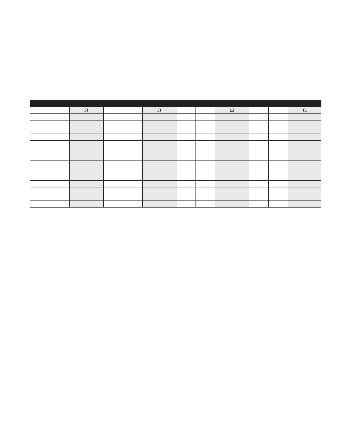
A good quality test meter capable of measuring up to 5,000 kΩ
(1 kΩ = 1000 Ω) is required to measure the sensor resistance. In
addition, the actual temperature must be measured with either a
high-quality digital thermometer, or if a thermometer is not avail-
able, a second sensor can be placed alongside the one to be
tested and the readings compared.
First, measure the temperature using the thermometer and then
measure the resistance of the sensor at the control. The wires
from the sensor must not be connected to the control while
the test is performed. Using the chart below, estimate the tem-
perature measured by the sensor. The sensor and thermometer
readings should be close. If the test meter reads a very high
resistance, there may be a broken wire, a poor wiring connection
or a defective sensor. If the resistance is very low, the wiring may
be shorted, there may be moisture in the sensor or the sensor
may be defective. To test for a defective sensor, measure the
resistance directly at the sensor location.
Do not apply voltage to a sensor at any time as damage to
the sensor may result.
TEMPERATURE RESISTANCE TEMPERATURE RESISTANCE TEMPERATURE RESISTANCE TEMPERATURE RESISTANCE
°F °C °F °C °F °C °F °C
-50 -46 490,813 20 -7 46,218 90 32 7,334 160 71 1,689
-45 -43 405,710 25 -4 39,913 95 35 6,532 165 74 1,538
-40 -40 336,606 30 -1 34,558 100 38 5,828 170 77 1,403
-35 -37 280,279 35 2 29,996 105 41 5,210 175 79 1,281
-30 -34 234,196 40 4 26,099 110 43 4,665 180 82 1,172
-25 -32 196,358 45 7 22,763 115 46 4,184 185 85 1,073
-20 -29 165,180 50 10 19,900 120 49 3,760 190 88 983
-15 -26 139,403 55 13 17,436 125 52 3,383 195 91 903
-10 -23 118,018 60 16 15,311 130 54 3,050 200 93 829
-5 -21 100,221 65 18 13,474 135 57 2,754 205 96 763
0 -18 85,362 70 21 11,883 140 60 2,490 210 99 703
5 -15 72,918 75 24 10,501 145 63 2,255 215 102 648
10 -12 62,465 80 27 9,299 150 66 2,045 220 104 598
15 -9 53,658 85 29 8,250 155 68 1,857 225 107 553
Remove the front cover from the control.
Testing the Power
• Use an electrical meter set to measure (ac) voltage.
• Measure between the L and N terminals.
• The reading should be 115 V (ac) +/– 10%.
Hand Manual Override
The control includes a Hand Manual Override menu to check if
the control’s relays are operating and that the control is wired
correctly to the snow melting equipment.
Step 1 - Press Settings button.
Step 2 - Press Override button.
Step 3 - Press Manual Override.
Step 4 - Select Manual Override to Hand.
Step 5 - Press Back button.
Step 6 - The following outputs can be operated:
• System Pump relay
• Heat Relay
• Boiler Relay
Testing the Sensor Wiring
Testing the Control Wiring
For each relay output
• Use an electrical meter set to measure (ac) voltage.
• Measure between the relay wiring terminals.
• When the relay is off, the voltage should be 115 V (ac).
• When the relay is on, the voltage should be 0 V (ac).
Exiting the Hand Manual Override
• Exit the Manual Override by selecting Auto.
• Install the front cover.

12
In hydronic application modes, the control includes a
Maximum Heat operation where the control operates the
snow melting system to maintain the maximum allowed heat-
ing setpoints. This allows testing of the snow melting system
during warm weather.
Step 1 - Press Settings button.
Step 2 - Press Override button.
Step 3 - Press Manual Override.
Step 4 - Select Manual Override to Max Heat.
Step 5 - Press Back button. The control starts the
Max Heat operation.
Step 6 - Exit the Manual Override by selecting Auto.
When operating a hydronic snow melting system, it is necessary
to purge and bleed all air out of the system. The control includes
a Purge operation where the system, primary and boiler pumps
are all turned on to assist in purging air from the system.
Step 1 - Press Settings button.
Step 2 - Press Override button.
Step 3 - Press Manual Override.
Step 4 - Select Manual Override to Purge.
Step 5 - Press Back button. The control starts the
Purge operation.
Step 6 - Exit the Manual Override by selecting Auto.
The snow melting system can be manually turned off and the
control remains off until manually changed back to Auto. This
allows the installer or end user to permanently disable the snow
melting system without removing power from the control.
Step 1 - Press Settings button.
Step 2 - Press Override button.
Step 3 - Press Manual Override.
Step 4 - Select Manual Override to Off.
Step 5 - Press Back button. The control is now in the off
manual override.
Step 6 - Exit the Manual Override by selecting Auto.
The control is shipped pre-programmed with common settings.
The control has an
“
Installer
”
access level that allows full access
to all settings and a
“
User
”
access level that restricts the number
of settings available. The control defaults to the
“
User
”
access
level after 12 hours of operation.
To change to the
“
Installer
”
access level:
Step 1 - Press the Settings button.
Step 2 - Press the Toolbox button.
Step 3 - Press Access Level.
Step 4 - Press the Installer radio button.
Manual Override – Maximum Heat
Manual Override – Purge
Manual Override – Off
Access Levels
13
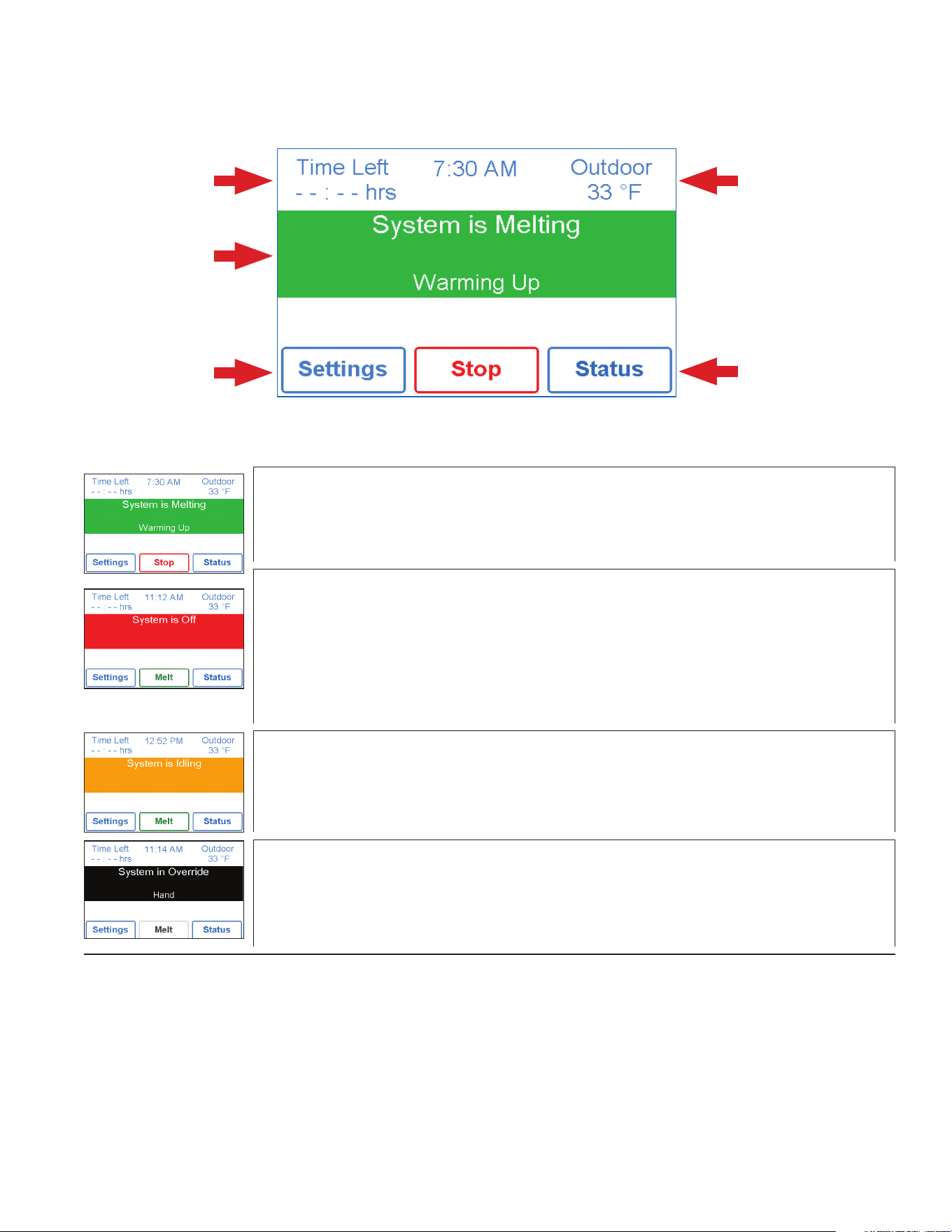
User Interface
View status of sensor
readings and equipment
Remaining melting
run time
System operation
information
Go to settings menu
to setup control
Information about slab and
outdoor conditions
SYSTEM IS MELTING
• The control has either detected snow/ice and automatically started or the control was
manually started.
• “Warming Up” is shown when the slab is below the slab target temperature.
SYSTEM IS OFF
• The snow melting system is off and is ready to detect snow or ice.
• “Warm Weather Shut Down” is shown when the slab and outdoor temperature are above the WWSD
setting. During WWSD, the snow will melt naturally due to warm outdoor temperatures.
• “Cold Weather Cut Off” is shown when the outdoor temperature is below the CWCO setpoint. The
outdoor temperature is so cold the heating system does not have capacity to melt snow.
• “Melt Pending” is shown when the system is off during CWCO but will resume melting once the
outdoor temperature increases above the CWCO setpoint.
SYSTEM IS IDLING
• The control is pre-heating the slab to the idling setpoint. This reduces the amount of time needed to
reach the melting setpoint in the event snow or ice is detected.
SYSTEM IN OVERRIDE / SYSTEM IN EXERCISING
• The control is in a manual override for testing, commissioning or exercising.
• The description field explains which type of override is active.
Home Screen
14
!
WARNING SYMBOL
The control has a error message. Press the warning symbol to determine
the error code and information on how to take corrective action. Refer to
the Troubleshooting section for a list of error codes.
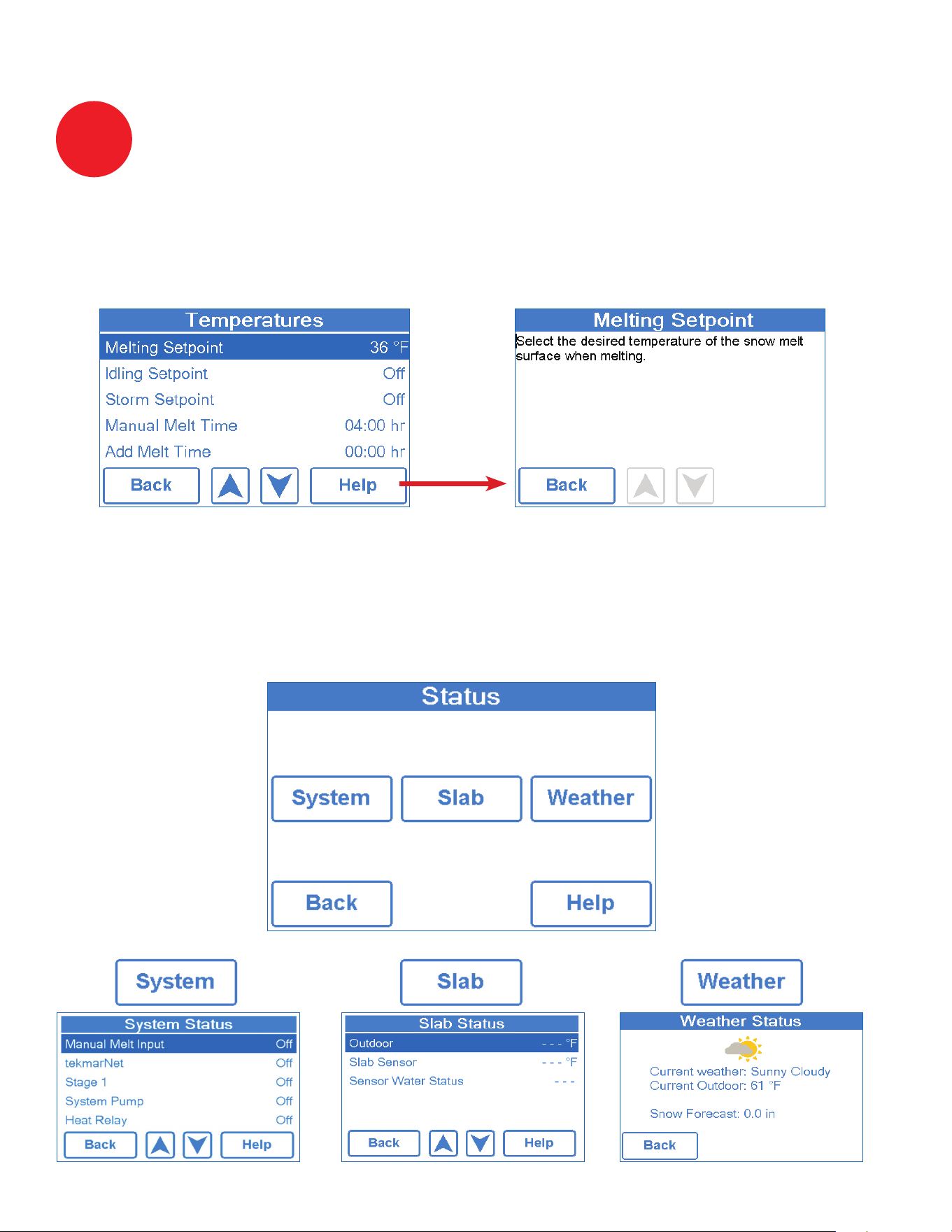
The display includes a Help screen for each setting. The Help screen provides a description of
the setting that is identical to the description found in the Installation and Operation Manual.
Step 1 - Press the Status button on the Home Screen.
Step 2 - Press either the System, Slab or Weather button.
Step 3 - Press up or down buttons to scroll through the list.
Symbols
Help Screen
Status Menu Navigation

15
Description Range Access
MANUAL MELT INPUT
When Manual Melt wiring terminal 8 is shorted to common wiring terminal 9, the control is
enabled and enters the melting operation unless prevented by warm weather shut down or cold
weather cut off. When the manual melt input is disconnected, the control completes the melting
cycle and then returns to off, idle or storm operation.
Conditions: Available
Off, Enabled
User
Installer
TEKMARNET
When tekmarNet communication is present, the status shows active. When there is no
tekmarNet communication, the status is off.
Conditions: Available
Off, Active
User
Installer
BOILER
Current status of the Boiler relay.
Conditions: Always available
On or Off
User
Installer
SYSTEM PUMP
Current status of the system loop pump.
Conditions: Always available
On or Off
User
Installer
HEAT RELAY
Current status of the heat relay.
Conditions: Always available
On or Off
User
Installer
Description Range Access
OUTDOOR
Current outdoor air temperature as measured by the outdoor sensor or from the tekmarNet sys-
tem. “– – –” is displayed when no outdoor temperature reading is available.
– – –,
-67 to 149°F
(-55.0 to 65.0°C)
User
Installer
SLAB TARGET
The slab target calculated by the control based on outdoor temperature and the melting, idling,
or storm setpoints. “- - -” is displayed when no heat is required.
– – –,
32 to 110°F
(0 to 43.0°C)
User
Installer
SLAB SENSOR
Current slab sensor temperature.
-58 to 167°F
(-50.0 to 75.0°C)
User
Installer
SENSOR WATER STATUS
Current status of snow/ice sensor moisture detector.
DRY or WET
User
Installer
System Status Menu
Slab Status Screen
16
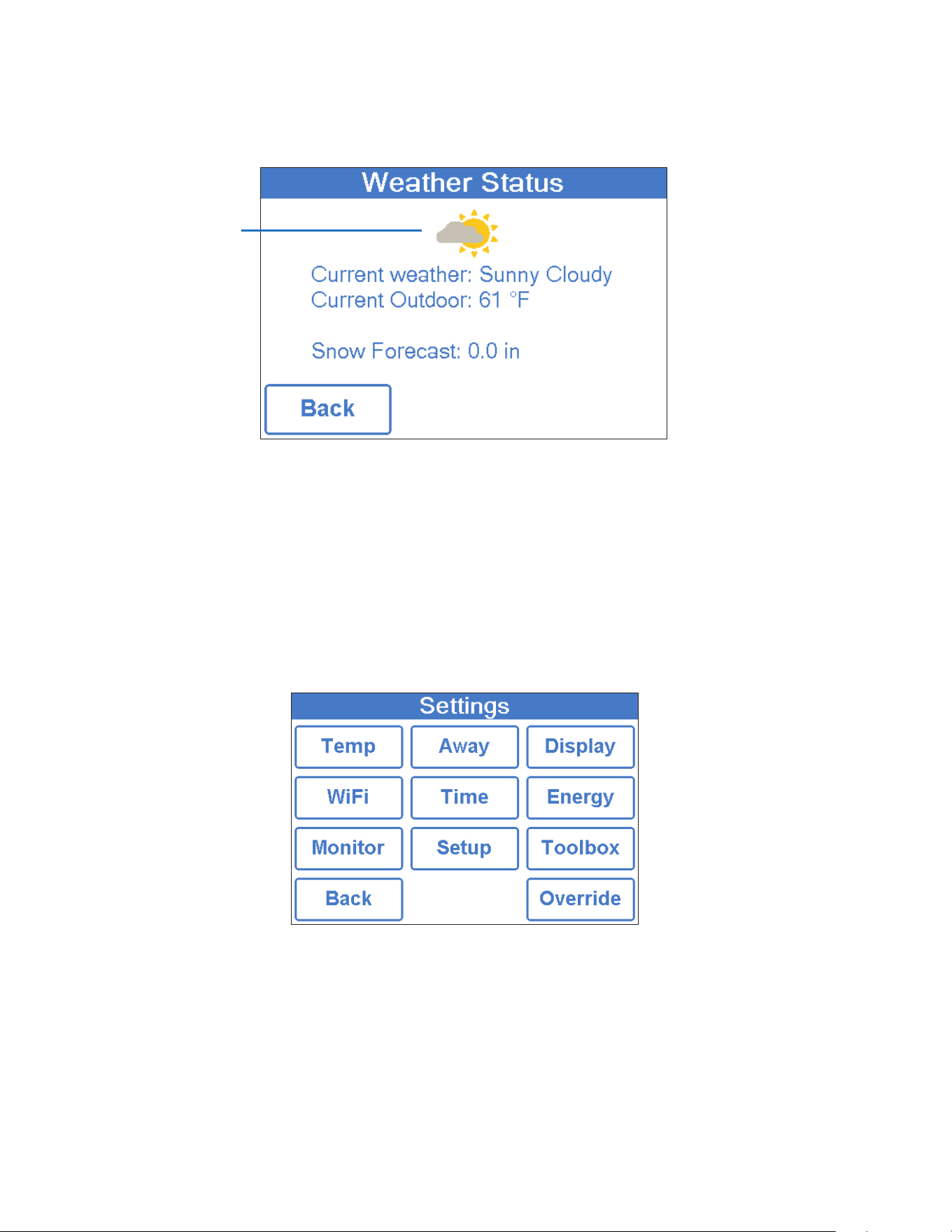
Current outdoor conditions
When WiFi is turned on, the control receives weather data from the Internet. The current weather,
outdoor temperature and forecast snow fall information is displayed.
Step 1 - Press the Settings button on the Home Screen.
Step 2 - Press one of the ten buttons.
Step 3 - Press up or down buttons to scroll through the list.
Step 4 - Press the highlighted setting name to change the setting value.
Weather Status Screen
Settings Menu Navigation
17

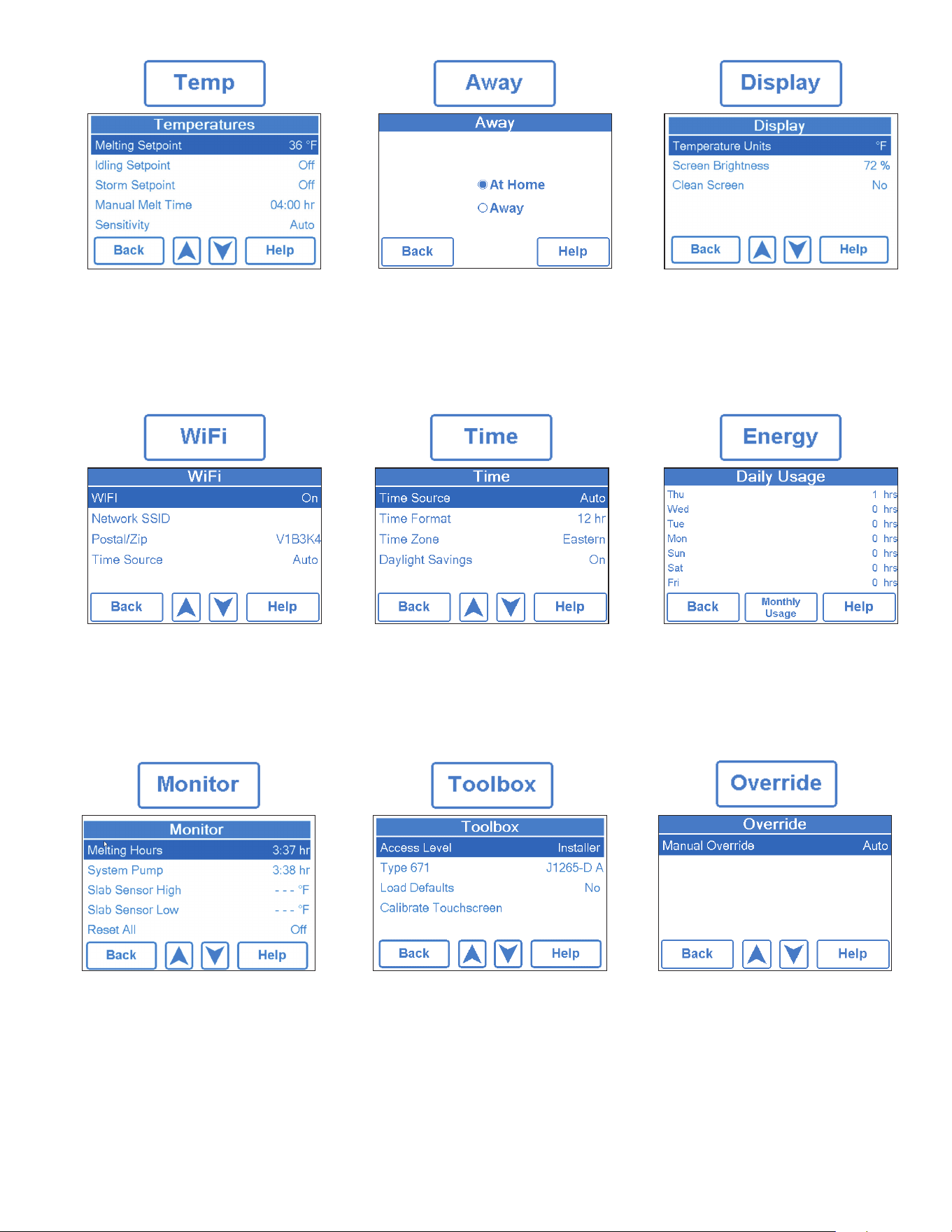
18
Description Range Access
MELTING SETPOINT
Select the desired temperature of the snow melt surface when melting.
32 to 95°F
(0.0 to 35.0°C)
Default = 36°F
(2.0°C)
User
Installer
IDLING SETPOINT
Select the desired temperature of the snow melt surface when idling. Idling preheats the slab
when the slab is dry but cold and allows faster reaction time to reach the melting temperature
when snow is detected. Recommended for commercial use only.
OFF, 20 to 95°F
(-6.5 to 35.0°C)
Default = Off
User
Installer
STORM SETPOINT
Select the desired temperature of the snow melt surface while operating in the storm operation.
Storm operation temporarily preheats the slab to allow faster reaction time to reach the melting
temperature when snow is detected. Storm operation is automatically activated by the Internet
weather forecast or manually started by a User Switch or Gateway.
Conditions: Always available.
OFF, 20 to 95°F
(-6.5 to 35.0°C)
Default = Off
User
Installer
MANUAL MELT TIME
Select the amount of running time when manually starting the system.
0:30 to 24:00 hours
Default = 4:00 hours
User
Installer
ADD MELT TIME
Select the amount of additional melting time after the Snow/Ice Sensor is dry. This allows low
spots on the slab to fully dry before the snow melting system is shut off
0:00 to 6:00 hours
Default = 0:00 hours
Installer
STORM RUN TIME
Select the amount of storm run time to pre-heat the slab when advised of a winter
storm warning.
0:30 to 24:00 hours
Default = 8:00 hours
Installer
SENSITIVITY
Select how sensitive Snow/Ice Sensor is to water detection.
Auto, Min, -2, -1,
Mid, +1, +2, Max
Default = Auto
Installer
WWSD
Select the temperature above which the snow melting system is shut off during warm weather.
This allows the snow or ice to melt off the slab naturally.
Auto, 32 to 95°F
(0.0 to 35.0°C)
Default = Auto
Installer
CWCO
Select the temperature below which the snow melting system is shut off during extremely cold
weather. Below this temperature, the heat loss of the slab exceeds the capacity of the boiler or
heating appliance.
Off, -30 to 50°F
(-34.5 to 10.0°C)
Default = 10°F
(-12.0°C)
Installer
Temp Menu
19
Description Range Access
TEMPERATURE UNITS
Select Fahrenheit or Celsius temperature units.
Conditions: Always available.
°F or°C
User
Installer
SCREEN BRIGHTNESS
Select the screen brightness.
Conditions: Always available.
0 to 100%
Default = 75%
User
Installer
CLEAN SCREEN
The Clean Screen timer locks the screen for 10 seconds allowing the user to wipe the screen
with a moist cloth. Do not use solvents to clean the screen.
Conditions: Always available.
No,Yes
User
Installer
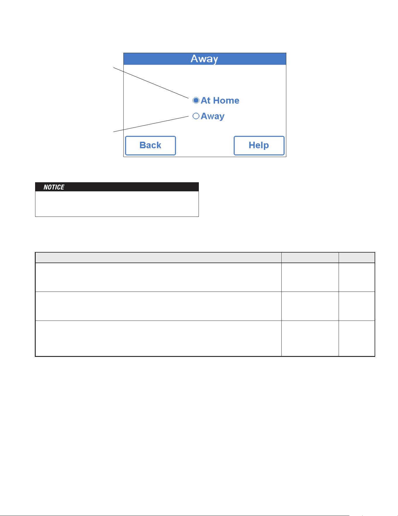
Away
Select away to prevent snow
melting operation and save energy.
At Home
Select at home to allow automatic
snow melting operation.
The home/away changes devices system-wide. All thermostats
and controls that are grouped together on a tekmarNet system
will also change together.
Away Menu
Display Menu
20
Description Range Access
WIFI
Enable or disable WiFi connectivity. The help screen displays the following information:
IP Address
Subnet Mask
Gateway
MAC Address
Conditions: Always available.
Off or On
User
Installer
NETWORK SSID
Select the WiFi network from the list.
Conditions: WiFi is set to On.
List of WiFi
Networks
User
Installer
ZIP/POSTAL CODE
Enter a US ZIP or Canadian postal code. The ZIP/Postal Code is used to provide the location
for the weather information. The weather service is available in the USA and Canada only
Conditions: WiFi is set to On.
US ZIP format
12345
Canada Postal Code
format A1B2C3
User
Installer
TIME SOURCE
Select to set to the time automatically or manually.
Conditions: WiFi is set to On.
Auto,
Manual
User
Installer
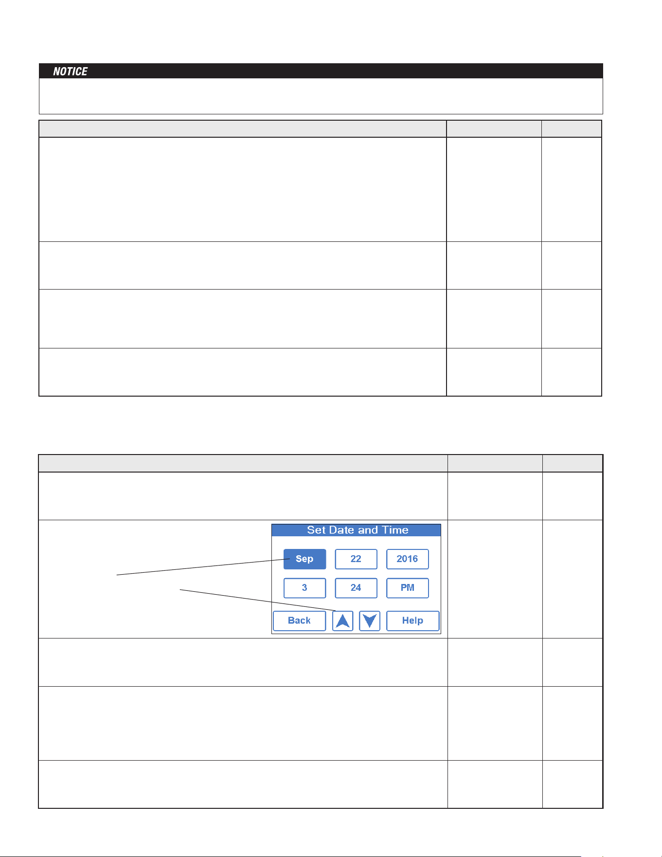
Description Range Access
TIME SOURCE
Select to set to the time automatically or manually. Auto is only available when WiFi is set to On.
Conditions: Always available.
Auto,
Manual
User
Installer
SET TIME AND DATE
Conditions: Time source set to manual.
N/A
User
Installer
TIME FORMAT
Select either 12 or 24 hour format.
Conditions: Always available.
12 hr,
24 hr
Default = 12 hr
User
Installer
TIME ZONE
Select the location’s time zone.
Conditions: Available when Time Source is set to Manual.
Hawaii, Alaska,
Pacific, Mountain,
Central, Eastern,
Atlantic,
NFLD,
(Newfoundland)
User
Installer
DAYLIGHT SAVINGS
Set Daylight Savings to On to automatically adjust for time changes in the spring and fall.
Conditions: Always available.
Off or On
Default = On
User
Installer
Before using the WiFi features of this product, you must accept the Terms of Use, as amended from time to time and available at
Watts.com/terms-of-use. If you do not accept these terms, this product can still be used without WiFi features.
• Press box field.
• Then adjust with arrow buttons.
WiFi Menu
Time Menu
21
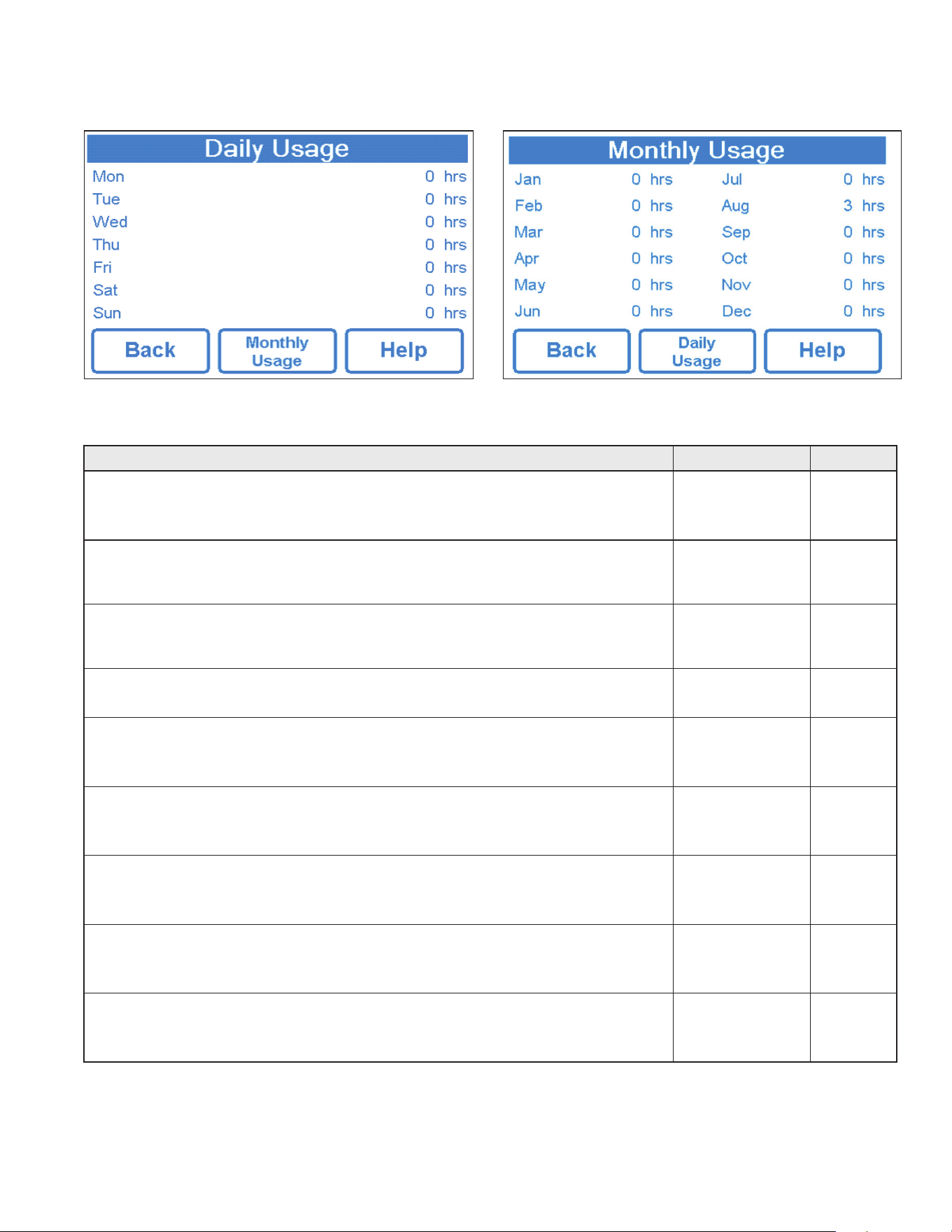
Amount of time the system has been on in hours per day. Amount of time the system has been on in hours per month.
Description Range Access
MELTING HOURS
Records the number of melting hours since the counter was last reset.
Conditions: Always available.
0 to 999999 hours
User
Installer
HEAT HOURS
Records the number of hours the boiler fired or the electric cable heated since the counter was
last reset.
0 to 999999 hours
User
Installer
HEAT CYCLES
Records the number of cycles the boiler turned on or the electric cable heated since the counter
was last reset.
0 to 999999 cycles Installer
SYSTEM PUMP
Records the number of hours the system pump has operated since the counter was last reset.
0 to 999999 hours Installer
SLAB SENSOR HIGH
Records the highest measured slab temperature since the counter was last reset.
Conditions: Available when Snow/Ice is set to In-slab or Slab Sensor is set to On
-58 to 167°F
(-50.0 to 75.0°C)
Installer
SLAB SENSOR LOW
Records the lowest measured slab temperature since the counter was last reset.
Conditions: Available when Snow/Ice is set to In-slab or Slab Sensor is set to On
-58 to 167°F
(-50.0 to 75.0°C)
Installer
OUTDOOR HIGH
Records the highest measured outdoor air temperature since the counter was last reset.
Conditions: Always available.
-67 to 149°F
(-55.0 to 65.0°C)
Installer
OUTDOOR LOW
Records the lowest measured outdoor air temperature since the counter was last reset.
Conditions: Always available.
-67 to 149°F
(-55.0 to 65.0°C)
Installer
RESET ALL?
Resets all the counters in the monitor menu at once.
Conditions: Always Available.
No, Yes Installer
Energy Menu
Monitor Menu
22
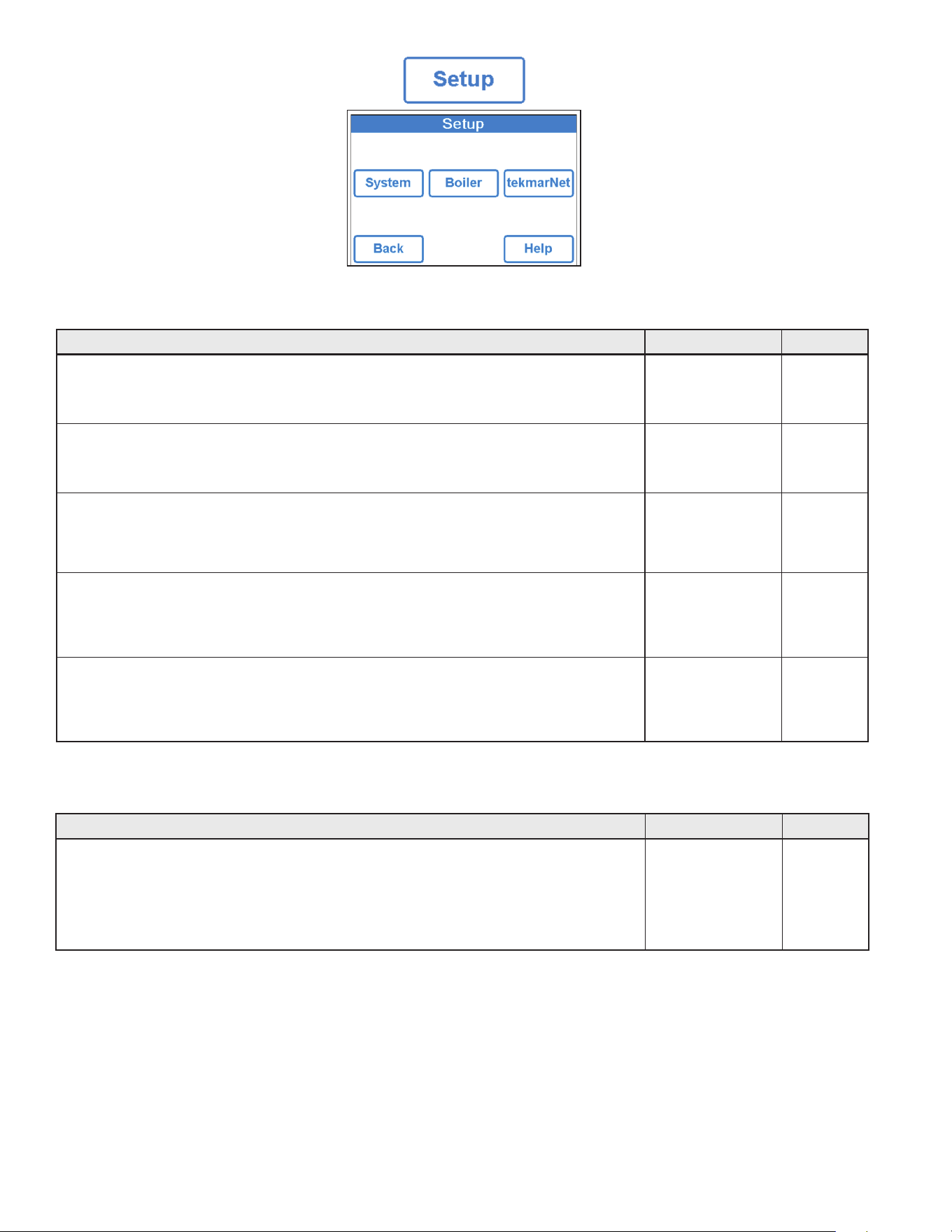
Description Range Access
SNOW/ICE SENSOR
Select if a Snow/Ice Sensor 090 or 094 “Inslab”, or a Snow Sensor 095 “Aerial” is installed.
Conditions: Always available.
None,
In-slab, Aerial
Default = In-slab
Installer
SLAB SENSOR
Select if a Slab Sensor 072 or 073 is installed.
Conditions: Available when snow/ice sensor is set to None or Aerial.
Off or On
Default = Off
Installer
ECONOMELT
EconoMelt allows the user to mechanically remove snow then manually start the system to melt
the remaining thin snow layer or ice with an automatic stop when the sensor is dry. Requires
snow/ice sensor to be set to in-slab
Off or On
Default = Off
Installer
MAX MELT DAYS
Limit the amount of melting run time after snow is automatically detected by a Snow/Ice Sensor
090 or 094, or a Snow Sensor 095.
Conditions: Always available.
Off, 0.5 to 7 days
Default = 3 days
Installer
OUTDOOR SENSOR
Select if the outdoor air temperature is measured by the control, by a tekmarNet system or by
the Internet weather service.
Conditions: Always available.
Control,
tekmarNet, Internet
Default = Control
Installer
Description Range Access
BOILER TYPE
Select the type of boiler operated by the control.
Enable = Boiler relay turns on the heat source.
Control = Call for heat to tekmarNet control.
Conditions: Available when the ProMelt Smart Controller is connected to a tekmarNet system.
Enable,
Control Installer
Setup – System Setup Menu
Setup – Boiler Setup Menu

23
Description Range Access
ADDRESSING
The tekmarNet address of this control. To manually set the address, use the up or
down buttons.
Auto,
x:01 to bus x:24,
Installer
AUTO ADDRESS
The tekmarNet address of this control.
Conditions: Addressing is set to Auto
Auto
b:01 to b:24
1:01 to 1:24
2:01 to 2:24
3:01 to 3:24
Installer
MANUAL ADDRESS
The tekmarNet address of this control when manually assigned
Conditions: Addressing is set to Manual
Manual
b:01 to b:24
1:01 to 1:24
2:01 to 2:24
3:01 to 3:24
DEVICE COUNT
Provides a count of all the tekmarNet thermostats, setpoint controls and snow melting controls
on the tekmarNet System.
1 to 24 Installer
SNOW MELT ZONE
Select the snow melting zone that this control operates. Snow zone 1 has the highest priority
while snow zone 12 has the lowest priority.
1 to 12 Installer
TRACK ZONE
Select to track and record the running hours of snow zone 1 and repeat this run time on this
control. This allows snow melting zones without a snow/ice sensor to automatically start.
Off or On Installer
MELT GROUP
A User Switch or Gateway may be used to manually start melting the zone. Set the Melt Group
number to the corresponding Setpoint Enable number on the User Switch.
1 to 12 Installer
STORM GROUP
A User Switch may be used to manually start storm operation of the snow zone. Set the Melt
Group number to the corresponding Setpoint Enable number on the User Switch.
1 to 12 Installer
PRIORITY
Select the priority of the snow melting system.
Off, Conditional, Full
Default = Off
Installer
AWAY SCENE
Select if the control should accept or ignore the away command from a tekmarNet system.
Conditions: Always available.
Off or On
Default = On
Installer
TN4 SYSTEM PUMP
Select if the system pump located on the tekmarNet System Control should operate when the
snow melt zone is heating.
Off or On Installer
tekmarNet Menu

24
Description Range Access
ERROR CODE
The current error code is displayed.
Conditions: Always available.
See Error Code
Section
User
Installer
ACCESS LEVEL
Select the access level of the control. This determines which menus and items are available
through the user interface.
Conditions: Always available.
User or Installer
Default = Installer
User
Installer
TYPE 671
Product information.
SW: J1288 1.0.0
SVN: XXX
Conditions: Always available.
J1288
Last 3 numbers
indicate software
version
User
Installer
LOAD DEFAULTS
Select “Yes” to reload the factory defaults on the control.
Conditions: Always available.
No, Yes
User
Installer
Description Range Access
MANUAL OVERRIDE
Manually override the normal automatic operation of the control to test the equipment or
operate the system at the maximum temperature limits.
Auto = Normal operation.
Max Heat = Operate hydronic system at maximum heat.
Hand = Manual override of each relay output.
Purge = Hydronic system purge operates pumps to help bleed air from the system.
Auto,
Hand,
Max Heat,
Purge,
Off
User
Installer
SYSTEM PUMP
Manually turn on the system pump during the HAND Manual Override.
Off or On
Default = Off
User
Installer
HEAT RELAY
Manually turn on the heat relay during the HAND Manual Override.
Off or On
Default = Off
User
Installer
BOILER ENABLE
Manually turn on the boiler during the HAND Manual Override.
Off or On
Default = Off
User
Installer
HAND DURATION
Select the amount of time that the HAND Override is in effect before returning to Automatic
operation.
0:10 to 72:00 hours
Default = 0:10 hour
User
Installer
MAX HEAT DURATION
Select the amount of time that Max Heat is in effect before returning to Automatic operation.
0:10 to 72:00 hours
Default = 24:00 hour
User
Installer
PURGE DURATION
Select the amount of time that the Purge is in effect before returning to Automatic operation.
0:10 to 72:00 hours
Default = 0:10 hour
User
Installer
Toolbox Menu
Override Menu

25
Watts
®
Home App
Before using the WiFi features of this product, you must accept
the Terms of Use, as amended from time to time and available
at Watts.com/terms-of-use. If you do not accept these terms,
this product can still be used without WiFi features.
This product requires WiFi WPA2 security. WiFi networks with
security disabled or that use WEP are not supported.
To view and adjust the ProMelt Smart Controller using a mobile
phone or tablet, download the Watts Home mobile app from the
Apple
®
iTunes
®
Store or from the Google Play
®
Store.
Step 1 - Create a new account. Then sign in using your user-
name and password.
Step 2 - On the control, go to the WiFi menu and press Regis-
ter Device.
Step 3 - Press the Location name and Add New Device.
Step 4 - Enter the 8 digit code from the control into the mobile
app. Then enter the control's device name.
The control is now listed on the Devices page. Controller will
show tekmar brand on your Home app.
26
Sequence of Operation
A snow melting system can offer a safe, convenient, and cost
effective way of removing snow and ice from the snow melting
slab and similar surfaces. Safety is increased by activating the
snow melting system as soon as the snow falls rather than wait-
ing for mechanical snow removal after snow has accumulated.
This eliminates slip hazards and reduces the risk of injury by
mechanized snow melting equipment, thereby reducing potential
liability costs. The elimination of snow plow equipment and cor-
rosive salts also reduces damage to the slab surface and to the
environment. When controlled correctly, snow melting systems
can be cost competitive compared to mechanical snow removal.
The snow melting control can operate in one of four different ways:
Melt Heats the slab to melt snow or ice. Default is 36°F (2°C)
Idle Preheats the slab just below freezing to shorten the time
required to melt snow. Default is off.
Storm Temporarily preheats the slab just below freezing to
shorten the time required to melt snow. Default is off.
Off Snow melting system is off
The display shows the control operation in the home screen.
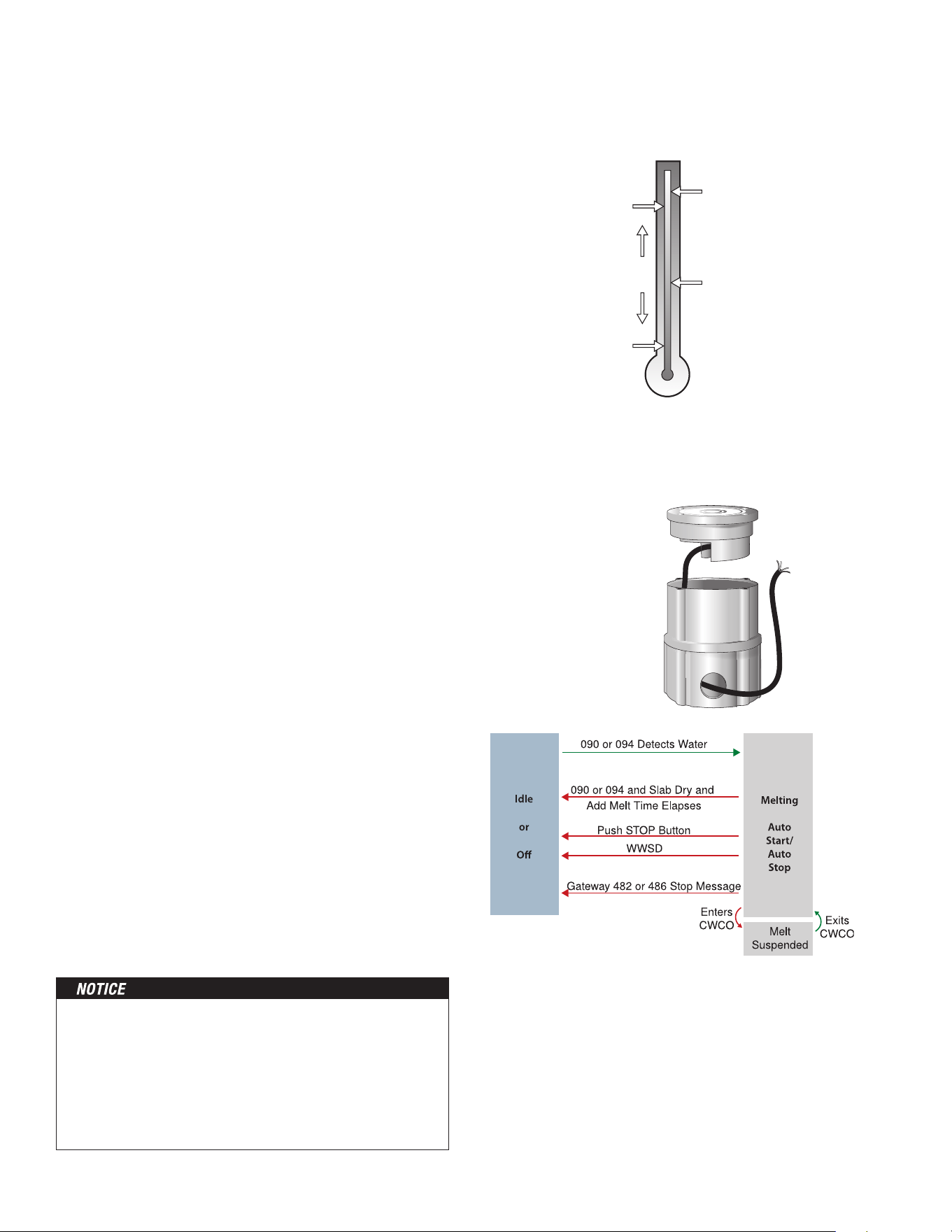
Automatic start and stop operation requires the installation of
a Snow/Ice Sensor 090 (65' or 20 m cable) or 094 (208' or 63
m cable). The sensor is installed in-slab level with the melting
surface. The control continually monitors the sensor for the
presence of moisture and slab temperature conditions in which
snow or ice may be present. When moisture is detected, the
control shows “Sensor Water Status – Wet” in the Slab Status
menu. When the sensor is dry the control shows “Sensor
Water Status – Dry”. The control includes a Sensitivity setting in
the Temperatures menu that allows the installer to adjust the
amount of moisture required to start and stop the melting
operation. In areas with low amounts of dust and/or air pol-
lution, the sensitivity may need to be increased. The default
sensitivity setting is Auto. This setting allows the control to
automatically determine the best suitable sensitivity setting for
the installation.
When moisture is detected and the control is not in WWSD or
CWCO or Away, the control will automatically start the snow
melting system. As the snow or ice melts and the slab dries off,
the sensor also dries off at the same time. When the sensor is
dry, the snow melt system automatically shuts off. If there are
low spots on the slab surface that dry off slower than the sen-
sor, additional melting run time can be included by adjusting the
Additional Melt Time setting in the Temperatures menu.
If the snow melting system is manually stopped, the
snow/ice sensor must fully dry before it is able to detect
a new snow fall and automatically start the snow
melting system.
Snow/Ice Sensor
090 or 094
Outdoor
Temperature
Slab
Temperature
MELT
IDLE or STORM
WWSD
CWCO
Control enters
Idle and waits
for Melt Enable
Snow Melting Overview
Melt – Automatic Start and Stop
The slab temperature must reach the slab target in order for
the system to shut off automatically. The capacity of the heat
source must be sized to ensure melting as low as the cold
weather cut off. In addition, the heat source maximum tem-
perature setting must be set to provide the full capacity of the
heating appliance. For example, boiler aquastats should be set
to 180°F (82°C). Failure to meet these requirements may result
in the snow melting system not automatically shutting off when
the slab is dry.
27
When a Snow/Ice Sensor 090 or 094 is installed, the installer
can choose to select to either automatically or manually start the
snow melting system. Selecting EconoMelt to On allows snow
removal using a snow plow or shovel. The remaining thin layer of
snow or ice that mechanical snow removal methods are unable
to remove can be melted using the manual start operation. The
snow melting system stops when the sensor is dry. The factory
default for EconoMelt is Off.
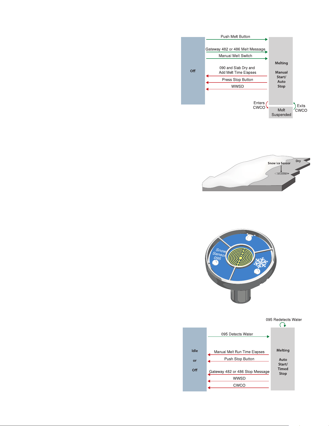
Automatic start with a timed stop operation requires the instal-
lation of a Snow Sensor 095. The sensor is aerial mounted on a
pole near the melting surface. It is highly recommended to also
install a Slab Sensor 072 (20' or 6 m cable) or 073 (40' or 12
m cable) in order to regulate the slab temperature and operate
the snow melting system at the highest possible efficiency. The
control continually monitors the snow sensor for the presence
of moisture and slab temperature conditions in which snow or
ice may be present. When moisture is detected, the control will
show “Sensor Water Status Wet” in the Slab Status menu. When
the sensor is dry the control will show “Sensor Water Status Dry”.
The control includes a Sensitivity setting in the Temperatures
menu that allows the installer to adjust the amount of moisture
required to start and stop the melting operation. In areas with low
amounts of dust and/or air pollution, the sensitivity may need to
be increased. The default sensitivity setting is Auto. This setting
allows the control to automatically determine the best suitable
sensitivity setting for the installation.
When moisture is detected and the control is not in WWSD or
CWCO or Away, the control automatically starts the snow melting
system. The snow melting system operates to heat the slab to
the slab target temperature and continues to operate until the
time set by the Manual Melt Run Time in the Temperatures menu
elapses. If the 095 re-detects water, the timer is restarted to
operate for the full run time.
Snow
Sensor 095
A Snow/Ice Sensor 090 or 094 automatically shuts off the snow
melting system when the water sensor is dry. Due to the con-
struction of the slab and the layout of the heating pipe or electri-
cal cable, there may be areas that do not melt completely. The
Additional Melt Time setting in the Temperatures menu allows the
installer to set addition melting time after the sensor is dry.
Melt – EconoMelt
Additional Melting Time
Melt – Automatic Start and Timed Stop
28
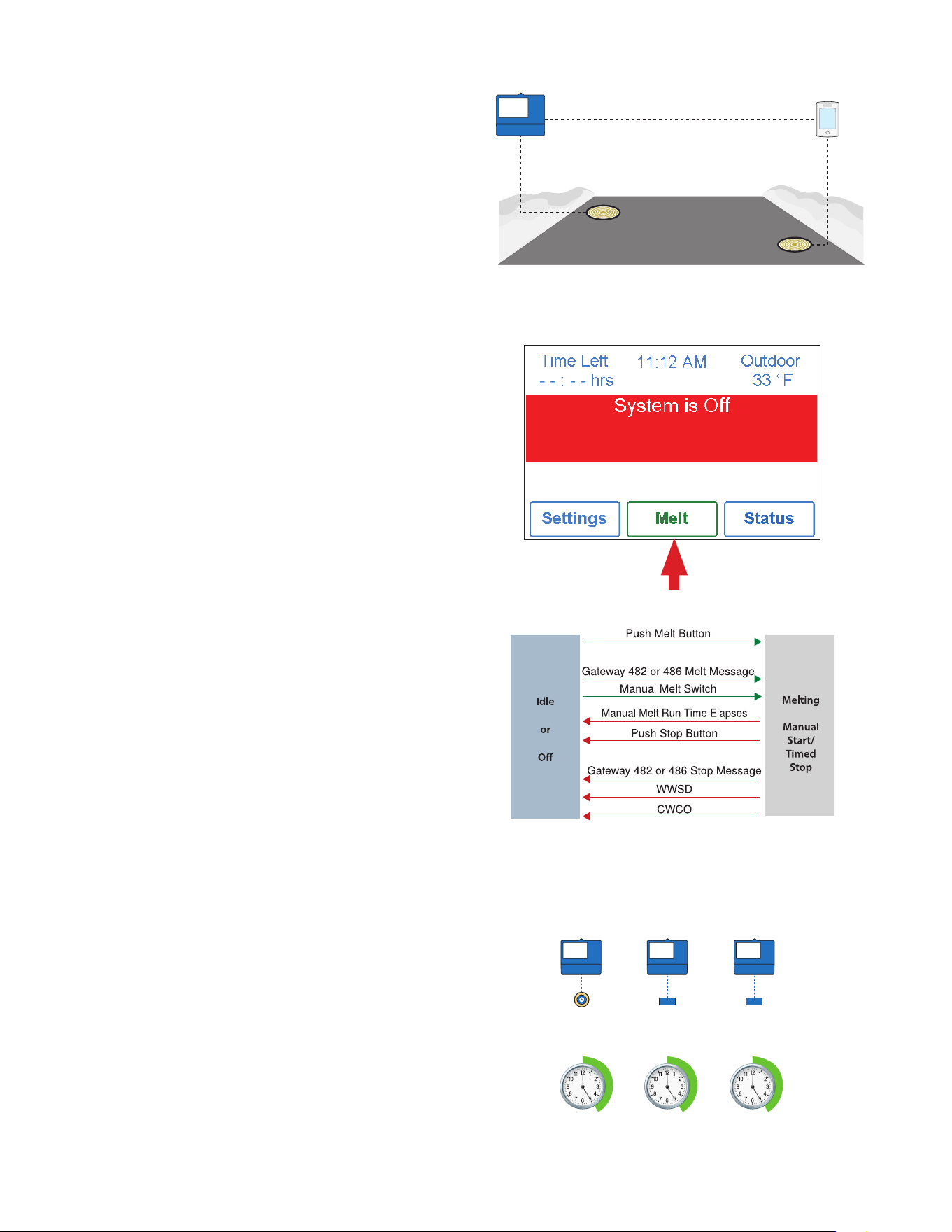
The snow melting system can be started manually by one of the
different methods:
• Touch the Melt button on the control display
• Through a Gateway 482 or 486 melt request message
• By manually connecting the Manual Melt and Com wiring
terminals 8 and 9 together.
• Through your Watts Home App
Once manually started and the slab warms up to the slab target,
the snow melting system runs until the time set by the Manual
Melt Run Time setting in the Temperatures menu elapses.
If a manual start has been provided and a Snow/Ice Sensor
detects water, the control changes from manual melt to
automatic operation. The snow melting system runs until the
sensor is dry and the Additional Melt Time elapses.
The ProMelt Smart Controller can be paired together with a
654/653 to allow two Snow/Ice sensors 090 or 094 or Snow
Sensors 095 to be installed for a single zone. This provides full
redundancy and increases the snow detection area.
Both sensors are used to detect snow or ice and if either sensor
is wet the snow melting zone starts melting. The control contin-
ues to operate until both sensors are dry. This allows snow or
ice detection over a wider area. In the event of a sensor failure,
the control continues to operate normally, giving building mainte-
nance staff time to troubleshoot and replace the faulty sensor
if necessary.
Press Melt button to start melting operation
The snow melting system can have multiple zones. Zones have
the option to track the melting run time of zone 1. This is useful
in cases where zone 1 has an automatic Snow / Ice Sensor
installed and the remaining zones do not. This allows zones 2
to 12 to gain the functionality of automatic starting and stopping
with only one Snow / Ice sensor installed in the system.
When zone 1 detects snow or ice, it starts melting. Zones with
tracking enabled can also start melting unless priority is selected.
When the sensor in zone 1 is dry or the Manual Melt Run Time
has fully elapsed, it sends a signal to the tracked zones that zone
1 has stopped. Each zone can continue to operate to complete
their own Additional Melt Time after which the zone stops heat-
ing and returns to the Off or Idle operation. Zones with priority
selected start after zone 1 has finished melting and repeat the
same run time as zone 1.
Zone 1
Track Melt Start and Stop
Records
Run Time
Snow / Ice
Sensor
Slab
Sensor
Slab
Sensor
Zone 2 Zone 3
Repeats
Zone 1 Run
Time + Add
Melt Time
Repeats
Zone 1 Run
Time + A
dd
Melt Time
Tandem Snow/Ice Detection
Melt – Manual Start and Timed Stop
Melt - Tracked Start and Stop
29
When the snow melting system starts from a cold temperature,
there may be a long time delay before the slab is warm enough
to melt snow. This time delay allows snow to accumulate on the
slab which is not acceptable in some commercial and institution-
al applications. To decrease the start-up time, the slab can be
pre-heated to maintain a minimum temperature. This is known
as the Idle temperature. Idling requires large energy consumption
and is generally recommended for institutional and/or commer-
cial installations where safety concerns are paramount. The
display shows “System is Idling” when the control is in
idle operation.
When designing a snow melting system, an engineer may specify
the amount of allowed snow accumulation as the Snow-Free
Area Ratio. There are three different levels. A Snow-Free Area
Ratio of 1 is defined as a system that melts all snow as it falls
with no allowed accumulation. This requires that the Idle tem-
perature be set just below freezing. Examples of these types of
applications include:
• Hospital emergency areas
• Helicopter landing pads
• Parking garage ramps
A Snow-Free Area Ratio of 0.5 is defined as a system with partial
snow accumulation on the slab but not in all areas. These types
of systems may also use Idling but usually set at a
temperature several degrees below freezing to reduce energy
consumption. Applications may include:
• Steep residential driveways
• Commercial sidewalks
• Loading docks
A Snow-Free Area Ratio of 0 is defined as a system that allows
snow accumulation. These systems operate the snow melting
system from a cold start resulting in the lowest energy consump-
tion costs and the longest times to start melting snow. In this
case set the Idle to off. This is recommended for most residential
applications such as:
• Flat residential driveways
• Patios
• Residential sidewalks
Some systems are designed for keeping a slab surface free of
ice rather than free of snow. The most common applications
include:
• Car wash bays and aprons
• Aircraft hanger aprons
• Turf conditioning on golf course greens
These systems require the use of Idling at or near freezing through-
out the winter and may result in high energy consumption.
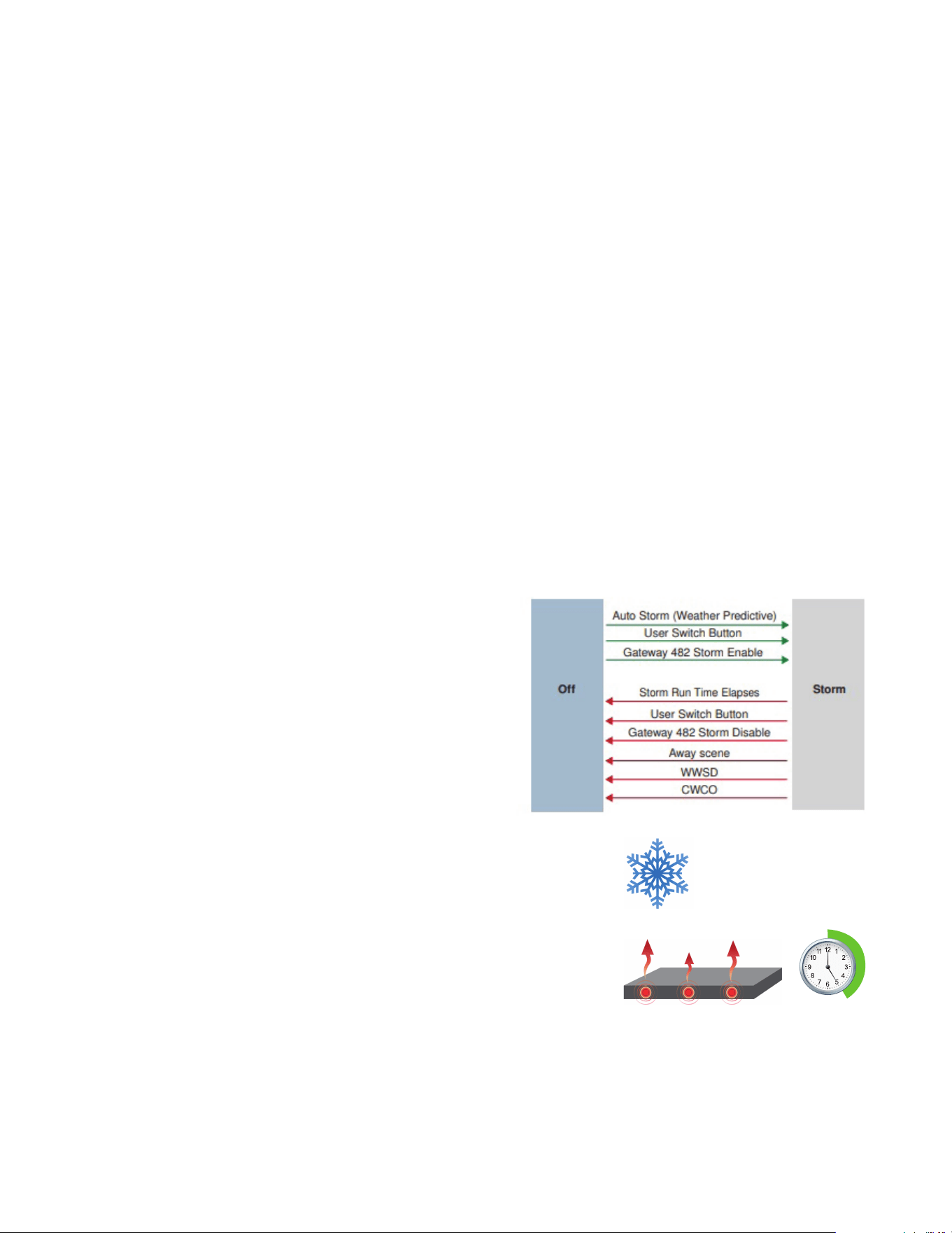
The Storm operation combines the benefits of a fast response
time together with lower operating costs. Typically the storm tem-
perature is set below freezing to maximize energy savings.
When the storm operation is manually started, the snow melt
system heats the slab up to the melting temperature and
completes a melting cycle.
Auto Storm
The control automatically checks an Internet weather service to
determine the snowfall forecast for a region based upon the US
ZIP or Canadian postal code. When the Storm feature is on and
snowfall is predicted, the control automatically heats the slab to
the storm setting.
When connected using tekmarNet, a 671 can automatically start
the storm operation on a Snow Melting Control 654. To do this
set the 671 and the 654 to use the same Storm Group number.
Manual Storm
The storm operation is manually started by a User Switch 480
and 481 or a Gateway 482. The manual storm uses the Storm
Group number in the tekmarNet menu.
Setup Procedure
Step 1 - Set the ProMelt Smart Controller Storm Group
number from 1 to 12. The default is 12.
Step 2 - Set the User Switch or the Gateway to use the
corresponding Storm Group number.
When the User Switch button is pressed, the ProMelt Smart
Controller will enter the Storm Operation. Likewise, activating the
Storm Group on the Gateway cause the ProMelt Smart Controller
to enter the Storm Operation.
If
Then
fo recast
Idle Operation
Storm Operation
30
Dividing a system into a number of snow melting zones and pri-
oritizing the zone operation reduces the size requirements of the
hydronic heating plant or the amperage of the electrical service
panel. This results in lower initial capital cost of the snow melting
system. The trade off is that some snow melt zones may not be
able to melt as soon as the snow fall begins and the user must
tolerate snow accumulation on the slab.
The snow melt system using Snow Melting Control ProMelt
Smart Controller may have up to 12 snow melt zones. Zone 1
has the highest priority and zone 12 has the lowest. The priority
setting in the tekmarNet® menu allows the installer to select the
level of zone priority for the entire snow melt system. Changing
the priority setting on one control will update on all other snow
melt controls at the same time. The zone priority has 3 setting
levels. There is some risk that lower priority zones may ice up
when they are shut off by the higher priority zone. For example, if
a high priority zone should finish melting and allow a lower priority
zone to start melting, and then a new snow fall occurs, the high
priority zone will shut off the lower priority zones. This may poten-
tially allow the lower priority zones to ice over. The limitations of
zoning and using priority must be carefully considered and dis-
cussed with the building owners and occupants when designing
the snow melting system.
Priority does not apply when the application mode is set to Boiler.
In this mode, the boiler is dedicated to a single snow
melting zone so priority is no longer applicable.
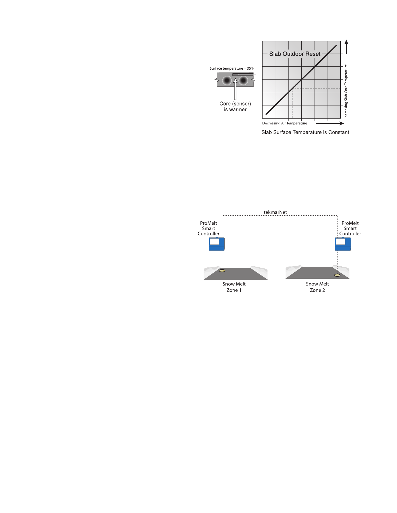
Controlling the slab temperature is critical to minimizing the cost
of snow melting. This requires that either a Snow/Ice Sensor
090 or 094 or a Slab Sensor 072 or 073 is installed. The Snow/
Ice Sensor contains a built-in slab temperature sensor. While the
control can operate without a slab sensor installed, operating
costs are much higher.
The slab is operated using slab outdoor reset. As the outdoor
temperature gets colder, the heat loss of the slab increases. In
order to keep the slab surface at a constant temperature while
operating, the inner core of the slab must be heated above the
melt, idle or storm temperature setting. The amount that the slab
inner core temperature is above the melt, idle or storm setting is
proportional to the outdoor temperature. Since the slab sensor
is installed below the surface of the slab, it is not measuring the
true slab surface temperature but rather the inner core tempera-
ture. The control automatically compensates for this temperature
difference. The Slab item in the Status menu displays the actual
measured temperature, so it is normal to view slab temperatures
that exceed the melt, idle, or storm temperature settings.
Slab Temperature Control
Snow Melt Zones and Priority
31
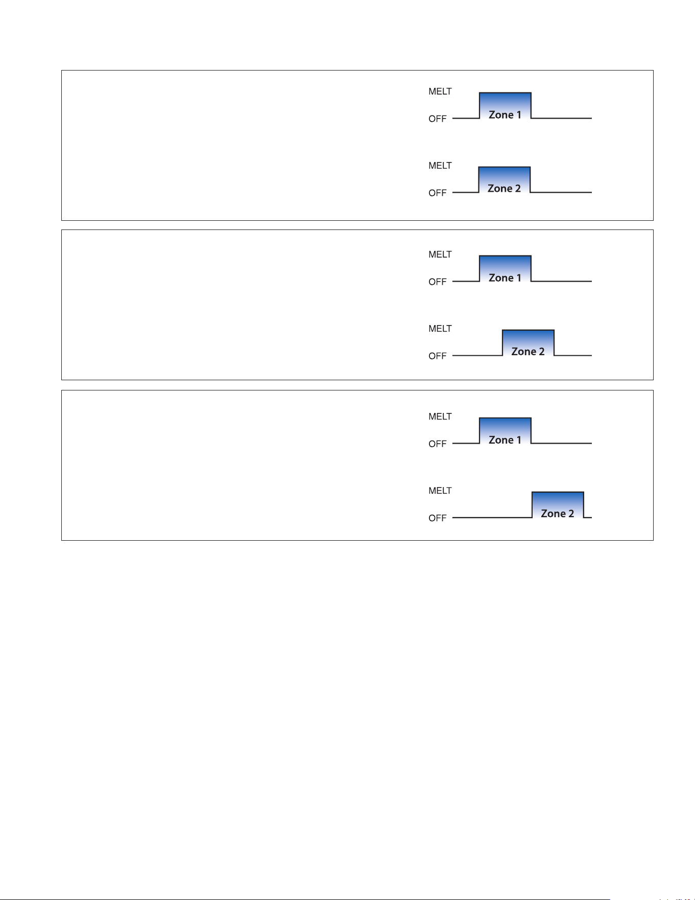
Priority = None
All zones have the same priority and can operate at the same time.
This setting is recommended when the boiler plant capacity is sized
larger than the heat loss of all zones at design conditions.
Priority = Conditional
The zone with the lower priority starts melting when the zone
with higher priority is warm enough to melt snow or ice.
This setting is recommended when the boiler plant capacity is
sized to be larger than the heat loss of each zone with some
extra capacity.
Priority = Full
The zone with the lower priority starts melting once the zone
with higher priority has finished melting all snow or ice from
the slab.
This setting is recommended when the boiler plant capacity is
sized to be the same as the heat loss of each zone at design
conditions.
Hydronic Priority Levels

32
The control has a built-in time clock that can be set manually. A
battery-less backup allows the control to keep time for up to 4
hours without power. The time clock supports automatic adjust-
ment for Daylight Saving Time (DST) once the day, month and
year are entered. Use the Time menu to set the correct time, day,
month and year.
While on vacation and away from a building, it may not be nec-
essary to operate the snow melting system. The away feature
allows the user to shut off the snow melting system to maximize
energy savings. The Away feature can be activated through the:
• Away menu
• tekmarNet User Switch 480 or 481
• tekmarNet Gateway 482 or 486
The tekmarNet system supports up to 8 scenes.
The ProMelt Smart Controller supports tekmarNet scenes
1 (normal operation) and 2 (away).
During tekmarNet scenes 3 through 8, the ProMelt Smart
Controller remains in scene 1 (normal operation).
During warm weather, the slab is warm enough to naturally
melt snow or ice. The control has a Warm Weather Shut Down
(WWSD) setting in the Temperatures menu that prevents the con-
trol from entering Melt, Idle or Storm operation in order to con-
serve energy. The control shows, “System is Off – Warm Weather
Shut Down” on the display when WWSD is in effect.
Automatic (Auto)
The control enters WWSD when both the slab temperature and
the outdoor temperature exceed the Melting Setpoint tempera-
ture setting by more than 2°F (1°C).
Manual WWSD
The control enters WWSD when the outdoor air temperature
exceeds the WWSD setting by 1°F (0.5°C) and when the slab
temperature exceeds 34°F (1°C). The control exits WWSD when
the outdoor air temperature falls 1°F (0.5°C) below the WWSD
setting or if the slab temperature falls below 34°F (1°C). This
allows the Melting Setpoint setting to be set higher than the
WWSD. This is useful when high slab temperatures are required
to melt the snow or ice. An example of this are installations using
paving bricks on top of sand and concrete layers.
Maintaining the melting or idling setpoint temperature during
extremely cold temperatures is not only expensive but may be
impossible if the heat loss of the slab exceeds the input capac-
ity of the heating plant or electric cable. The control turns the
snow melting system off when the outdoor air temperature drops
below the Cold Weather Cut Off (CWCO) temperature. This is a
safety and energy saving measure. The control shows, “System
is Off – Cold Weather Cut Off” on the display when CWCO is in
effect. When the temperature reaches the CWCO setting in an
actively melting system with an 090 or 094, melting is suspended
until the outdoor temperature rises above the CWCO setting at
which time melting is resumed. If an 090 or 094 is not installed,
melting is stopped when CWCO is in effect and melting does not
resume when the temperature rises above the CWCO setting.
Warm Weather Shut Down
Cold Weather Cut Off
Time Clock
Away Operation
tekmarNet Scene Operation

33
The control operates the system pump to operate continuously
during melt, idle and storm operation. The boiler relays and heat
pumps relays operate on a 20-minute pulse width modulation
cycle. The relay on time is determined by the calculated slab tar-
get and by the measured slab temperature reading. As the slab
temperature reaches the slab target, the on time per cycle of the
relay is reduced to prevent the slab temperature from overshoot-
ing. If no slab sensor is installed the heat relay remains on 100%
of the time until the Melt circle has completed.
When connected to a tekmarNet system, the ProMelt Smart
Controller can operate a boiler (Boiler Type set to Enable) or it
can call for heat from the tekmarNet boiler control (Boiler Type
set to Control)
Relay operation:
• System pump — operates continuously during melting, idling
or storm
• Heat relay — cycles on/off using Pulse Width Modulation to
control the slab temperature
• Boiler — cycles on/off using Pulse Width Modulation to con-
trol the slab temperature
The control operates the system pump and heat relay every 3
days to prevent pump and valve seizure.
The boiler or heat source is shut off and the snow melting system
continues to operate for 20 seconds to post purge heat from the
boiler to the load.
An outdoor air temperature is required for proper operation. The
control has the option to measure an outdoor air sensor or the
outdoor temperature can be provided through the tekmarNet
system or through the Internet weather service. This is selected
by the Outdoor Sensor setting in the System Setup menu.
Pulse Width Modulation Zone Operation
Outdoor Sensor
Exercising
Post Purge

34
1. Find: If the control shows the Warning Symbol on the screen, it is indicating a problem on the system.
2. Identify: Press the Warning Symbol to view the error code.
3. Solve: Use the chart below to match the error code to the one on the control. Use the description to solve the problem.
Description
TEMPERATURE MENU MEMORY ERROR
A memory error occurred and the control reloaded the factory default settings. The control stops operation until all settings in the
Setpoints menu are checked. To clear the error, set the access level to Installer and check all settings in the Temp menu.
SYSTEM SETUP MENU MEMORY ERROR
A memory error occurred and the control reloaded the factory default settings. The control stops operation until all settings in
the System Setup menu are checked. To clear the error, set the access level to Installer and check all settings in the System
Setup menu.
BOILER SETUP MENU MEMORY ERROR
A memory error occurred and the control reloaded the factory default settings. The control stops operation until all settings in the
Boiler Setup menu are checked. To clear the error, set the access level to Installer and check all settings in the Boiler Setup menu.
TEKMARNET MENU MEMORY ERROR
A memory error occurred and the control reloaded the factory default settings. The control continues operation as normal. To clear
the error, set the access level to Installer and check all settings in the tekmarNet menu.
WIFI MENU MEMORY ERROR
A memory error occurred and the control reloaded the factory default settings. The control continues operation as normal. To clear
the error, set the access level to Installer and check all settings in the WiFi menu.
MAX MELT DAYS ERROR
The control has operated in melting for the time set by the Maximum Melt Days setting. This error is usually created when there is a
mechanical system failure resulting in the snow melt slab not heating correctly. Clear the error message by touching the Reset button
while viewing the error message.
TEKMARNET COMMUNICATIONS ERROR
The tekmarNet communication bus has either an open or a short circuit. The result is that there are no communications. The error
clears automatically once the wiring fault has been corrected. To force the error to clear while allowing a short or open circuit to
continue, touch the Reset key.
ADDRESS TAKEN ERROR
Two devices have been manually set to the same address. The device continues to operate with this error but does not communicate
with the tekmarNet system. To clear this error, select an unused tekmarNet address or select automatic addressing.
SNOW ZONE TAKEN ERROR
Two snow melting controls have been manually set to the same snow zone number. The control continues to operate with this error.
To clear this error, select an unused snow zone number.
SYSTEM CONTROL LOST ERROR
The thermostat can no longer communicate to the tekmarNet system control. Check for open or short circuits in the tekmarNet
communication wiring. The error automatically clears once the tekmarNet system control has been detected. If the tekmarNet
system control was intentionally removed from the system, press the Reset button.
TANDEM SNOW/ICE SENSOR ERROR
There are two Snow / Ice Sensors installed in the zone and the tandem snow melting control 654 sensor has a problem. Locate
the other snow melting control and navigate to the Toolbox menu to determine and correct the problem. The control continues to
operate with this error. Press the Reset button to clear the error.
Troubleshooting
!
It is recommended to complete all wiring to ensure trouble free operation. Should an error occur, simply follow these steps:
Error Messages (1 of 2)

35
Description
DEVICE LIMIT ERROR
More than 24 devices have been connected to the tekmarNet communication bus. To clear the error, remove and relocate devices
to other available buses until the device count is 24 or less.
OUTDOOR SENSOR OPEN CIRCUIT ERROR
The control is unable to read the Outdoor Sensor 070. The control continues to operate and assumes an outdoor temperature of
32°F (0°C). Check for wiring faults and it may be necessary to replace the sensor. Once the error has been corrected, the error
message automatically clears.
OUTDOOR SENSOR SHORT CIRCUIT ERROR
The control is unable to read the Outdoor Sensor 070. The control continues to operate and assumes an outdoor temperature of
32°F (0°C). Check for wiring faults and it may be necessary to replace the sensor. Once the error has been corrected, the error
message automatically clears.
SLAB SENSOR OPEN CIRCUIT
The control is unable to read the Slab Sensor 072 or 073. Check for wiring faults and it may be necessary to replace the slab sensor.
Once the error has been corrected, the error message automatically clears.
SLAB SENSOR SHORT CIRCUIT
The control is unable to read the Slab Sensor 072 or 073. Check the wire for faults and it may be necessary to replace the slab
sensor. Once the error has been corrected, the error message automatically clears.
SNOW SENSOR YELLOW WIRE OPEN CIRCUIT
The control is unable to read the yellow wire connected to the Snow/Ice Sensor 090 or 094 or the Snow Sensor 095. Automatic
operation is disabled but manual start is still available. Check the snow/ice sensor yellow and black wires and any wire splices for
faults. It may be necessary to replace the sensor. Once the error has been corrected, the error message automatically clears.
SNOW SENSOR BLUE WIRE OPEN CIRCUIT ERROR
Due to an open circuit, the control is unable to read the blue wire connected to the Snow/Ice Sensor 090 or 094, or the Snow Sensor
095 on terminals 2 and 3. The control can no longer automatically detect snow or ice, but manual start of the snow melting system is
still available.
Check the snow/ice sensor or snow sensor blue and black wires and any wire splices for open circuits according to the sensor instal-
lation manual. It may be necessary to replace the sensor. Once the error has been corrected, the error message automatically clears.
SNOW SENSOR BROWN WIRE SHORT CIRCUIT ERROR
The control is unable to read the brown wire connected to the Snow/Ice Sensor 090 or 094. Check the snow/ice sensor brown
and black wires for faults. It may be necessary to replace the sensor. Once the error has been corrected, the error message
automatically clears.
SNOW SENSOR BROWN WIRE OPEN CIRCUIT ERROR
Due to an open circuit, the control is unable to read the brown wire connected to the Snow/Ice Sensor 090 or 094 on terminals 2 and
5. Idling and Storm is disabled and energy saving features such as Warm Weather Shut Down (WWSD) and Cold Weather Cut Off
(CWCO) are operated using the outdoor temperature only.
Check the snow/ice sensor brown and black wires for open circuits according to the sensor installation manual. It may be necessary
to replace the sensor. Once the error has been corrected, the error message automatically clears.
SNOW/ICE SENSOR ERROR
The control is unable to properly detect the Snow/Ice Sensor 090 or 094 on terminals 1, 2, 3, 4 and 5. The control can no longer
automatically detect snow or ice, but manual start of the snow melting system is still available.
Check the snow/ice sensor brown, yellow, red and black wires according to the sensor installation manual. It is important to check
any cable splices for loose wiring connections. It may be necessary to replace the sensor. Once the error has been corrected, the
error message automatically clears.
SNOW SENSOR ERROR
The control is unable to properly detect the Snow Sensor 095 on terminals 1, 2, 3, and 4. The control can no longer automatically
detect snow but manual start of the snow melting system is still available.
Check the snow sensor yellow, red and black wires according to the sensor installation manual. It may be necessary to replace the
sensor. Once the error has been corrected, the error message automatically clears.
Error Messages (2 of 2)

36
Symptom Look For... Corrective Action
Touchscreen is off Power to control Use electrical meter to measure 115 V (ac) voltage on input power L and N terminals.
System pump
always on
Display shows Idle
Idle operation requires that the system pump operate continuously while below the
melting temperature setting.
Blue short
Dirt or salt on snow/
ice sensor
The snow/ice sensor requires regular cleaning. Avoid using road salt on the snow
melting slab.
Slab is above melt
temperature
Slab Target The slab is heated to the slab target.
System running
with no snow
System is Idling Idling heats the slab when the temperature falls below the Idle temperature.
System is Melting
During cold weather cut off (CWCO), the system is shut off. If it shuts off during
a melt cycle, the system resumes melting once the outdoor temperature is
above CWCO.
Remaining Run Time System manually started.
Slab and Slab Target
The slab must reach the slab target temperature in order for the system to shut off.
Lower the cold weather cut off (CWCO) or increase the boiler aquastat setting.
Snow on slab but
system did not start
System is Off
System has been manually stopped and the automatic snow/ice sensor never
dried, thereby preventing the system from automatically starting.
Cannot register
device
Check WiFi signal
strength
May need to move control or router location.
Frequently Asked Questions

37
This page intentionally left blank

38
This page intentionally left blank

39
Technical Data
PROMELT SMART CONTROLLER
Literature PSC_A, PSC_C, PSC_U
Control Microprocessor control. This is not a safety (limit) control.
Packaged weight 4.3 lb. (1960 g)
Dimensions 6
5
/8" H x 7
9
/16" W x 2
13
/16" D (170 x 193 x 72 mm)
Display 3.5", color touchscreen
Enclosure Blue PVC plastic, NEMA type 1
Approvals CSA C US, meets class B: ICES & FCC Part 15
Ambient conditions -4 to 122°F (-20 to 50°C), < 90% RH non-condensing, outdoor use permitted when used in NEMA 3 enclosure
Power supply 115 V (ac) ±10%, 60 Hz, 20 VA
Relays 230 V (ac), 5 A, 1/3 hp
Manual melt call Short or 0 - 32 V(ac)
Communications WiFi 802.11n, 2.4 GHz, WPA2 encryption
Mobile app Apple
®
iOS 12 or higher, Android™ 10 or higher
Sensors NTC thermistor, 10 kΩ @ 77°F (25°C ±0.2°C) ß=3892
–Included Outdoor Sensor 070
–Optional Type: 072, 073, 087, 090, 094, 095

Limited Warranty: SunTouch (the “Company”) warrants each product to be free from defects in material and workmanship under normal usage for a period of one year from the date of original
shipment. In the event of such defects within the warranty period, the Company will, at its option, replace or recondition the product without charge.
THE WARRANTY SET FORTH HEREIN IS GIVEN EXPRESSLY AND IS THE ONLY WARRANTY GIVEN BY THE COMPANY WITH RESPECT TO THE PRODUCT. THE COMPANY MAKES NO OTHER
WARRANTIES, EXPRESS OR IMPLIED. THE COMPANY HEREBY SPECIFICALLY DISCLAIMS ALL OTHER WARRANTIES, EXPRESS OR IMPLIED, INCLUDING BUT NOT LIMITED TO THE IMPLIED
WARRANTIES OF MERCHANTABILITY AND FITNESS FOR A PARTICULAR PURPOSE.
The remedy described in the first paragraph of this warranty shall constitute the sole and exclusive remedy for breach of warranty, and the Company shall not be responsible for any incidental, special
or consequential damages, including without limitation, lost profits or the cost of repairing or replacing other property which is damaged if this product does not work properly, other costs resulting
from labor charges, delays, vandalism, negligence, fouling caused by foreign material, damage from adverse water conditions, chemical, or any other circumstances over which the Company has no
control. This warranty shall be invalidated by any abuse, misuse, misapplication, improper installation or improper maintenance or alteration of the product.
Some States do not allow limitations on how long an implied warranty lasts, and some States do not allow the exclusion or limitation of incidental or consequential damages. Therefore the above limita-
tions may not apply to you. This Limited Warranty gives you specific legal rights, and you may have other rights that vary from State to State. You should consult applicable state laws to determine your
rights. SO FAR AS IS CONSISTENT WITH APPLICABLE STATE LAW, ANY IMPLIED WARRANTIES THAT MAY NOT BE DISCLAIMED, INCLUDING THE IMPLIED WARRANTIES OF MERCHANTABILITY
AND FITNESS FOR A PARTICULAR PURPOSE, ARE LIMITED IN DURATION TO ONE YEAR FROM THE DATE OF ORIGINAL SHIPMENT.
IOM-ST-ProMeltSmartController 2349 EDP# 81020614 © 2023 Watts
USA: T: (888) 432-8932 • F: (417) 831-4067 • SunTouch.com
Canada: T: (888) 208-8927 • F: (905) 481-2316
Latin America: T: (52) 55-4122-0138 • SunTouch.com
Limited Warranty and Product Return Procedure
