P a g e | 1
JkorkM
1
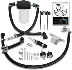
Gen 2.1 - 6.7L Power Stroke CP4 Disaster Prevention Kit
CP4-6.7F-BP-G2.1
2011-2023 Ford Truck – 6.7L Power Stroke Diesel
Installation Instructions
P a g e | 2
JkorkM
2
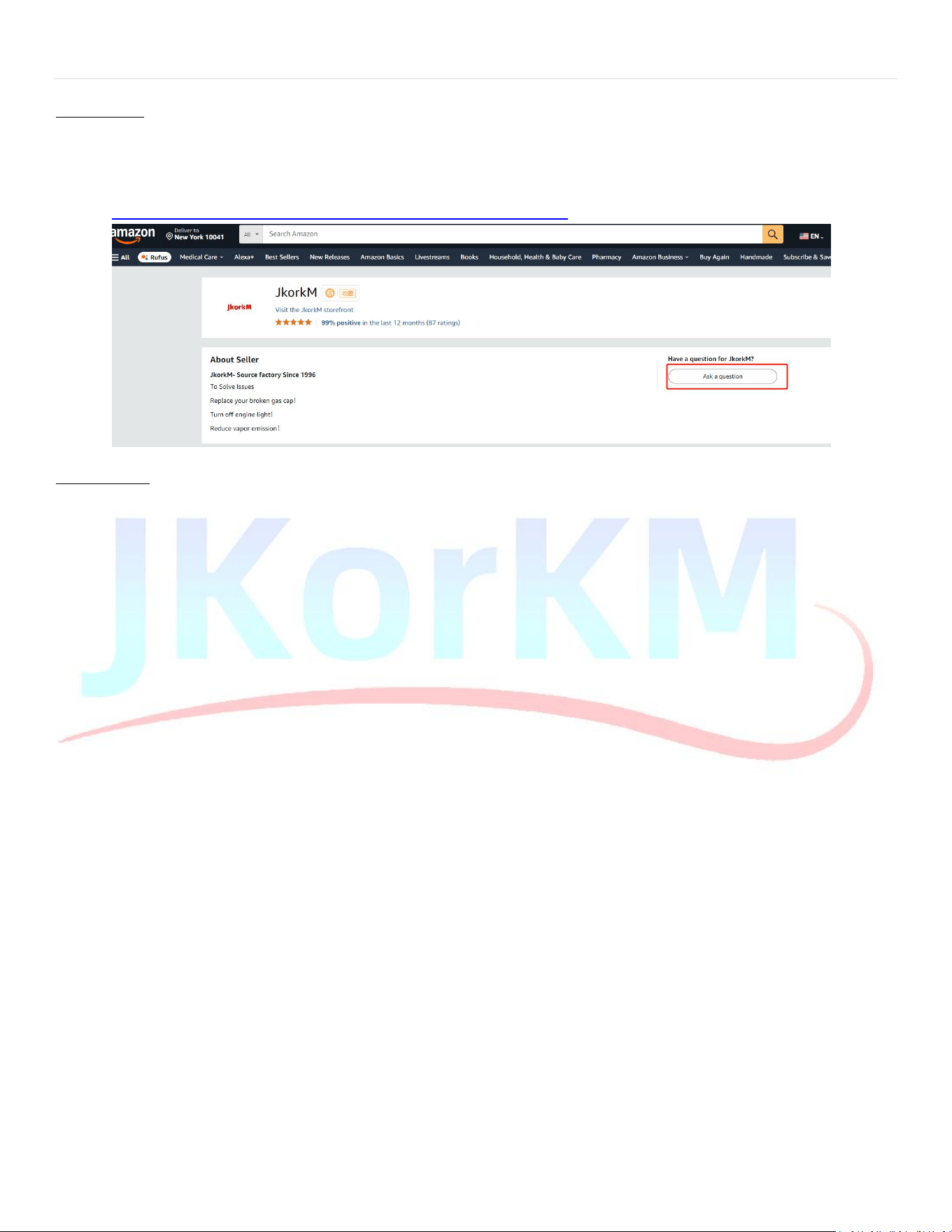
Install Video
Video instructions demonstrated on a 2021 F250 can be found by searching “Gen2.1 Ford CP4 Disaster
Prevention Kit” on YouTube。
If you can't find it, please feel free to contact the seller -JkorkM!
https://www.amazon.com/sp?ie=UTF8&seller=A1MP0INAE0ZYV6
Tips & Tricks:
Use compressed air to clean all components before installation to prevent contaminants from entering the fuel
system. Common rail diesel systems are highly sensitive to debris, so maintaining cleanliness during
installation
.
iscrucial.
If you suspect a failed CP4 high-pressure fuel pump after installing the kit, the fastest way to verify is by
cutting open the
Donaldson return fuel filter and checking the filter media for metal debris. (Longacre 52-
77750)
In rare instances on early model years, removing the casting flash on the lower intake may be required to
increase clearance for the Fuel Control Actuator (FCA) electrical connector on top of the CP4 fuel pump when
the Bypass Block is installed . Ensure proper clearance before the final intake assembly.
If you have prior experience removing the intake system, skip to Step 4 for Bypass Kit-specific instruc.tions.
Steps 1-3 detail the intake removal process to access the CP4 High-Pressure Fuel Pump (HPFP) (early models shown).
1. Remove the intake tube between the air filter and lower intake.
a. 2 hose clamps 8mm, some models may be 7mm.
b. Some models have an additional bolt holding the plastic resonator chamber that must be removed.
2. Remove the hot side charge pipe from turbo outlet and intercooler inlet for more room andaccessibility.
* The intake design changed in 2020, steps 2, 3, and 4 represent model years 2011-2019. For detailed instructions on
2020+ models, use the video found on page 2.
3. Remove the plastic upper intake. (Intake design changed in 2020, For trucks model year 2020 and higher, see
video instruction link on page 2)
Required Tools:
¼” drive sockets (deep well and short)
Universal joint
Wobble socket
Procedure:
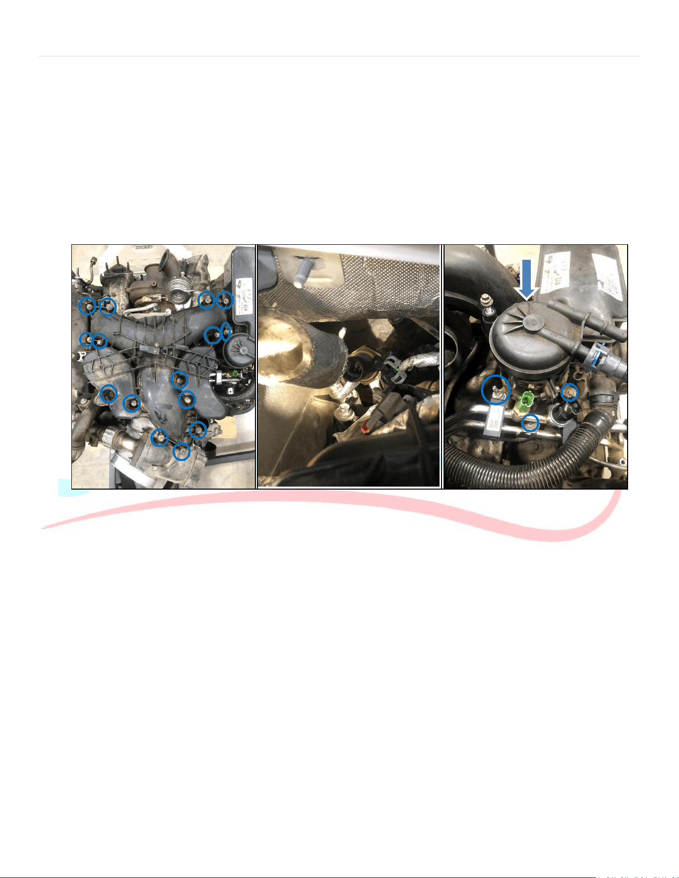
1.Remove Bolts:
There are a total of 15 bolts to be removed, each measuring 8mm (see Figure 1). Utilize the appropriate
sockets to facilitate removal.
2.Dipstick Fastener:
Note that one of the bolts also serves as a fastener for the dipstick (10mm nut). Make sure to remove this as
well.
P a g e | 3
JkorkM
3
3.Additional Bolts:
Remove the other two bolts securing the dipstick to the intake manifold and to each other.
4.Electrical Connections:
Disconnect all electrical connections and wires from the intake manifold. Additionally, removing the
insulation from the exhaust pressure sensor (see Figure 2) and its wire clip will improve access to the intake
fasteners.
5.Fuel Filter Housing:
To gain extra clearance for removing the intake manifold, disconnect the fuel filter housing. There are 4 bolts
to remove (see Figure 3). You might need to push or rotate the fuel hardline upwards to access the bolt
underneath. Once the fuel line is detached, place it back on the lower hardline to keep it clean. Be cautious to
avoid introducing any debris into the filter or fuel line.
Figure 1: Intake removal Figure 2: Insulation Removal Figure 3: Fuel Filter housing removal
4. Remove the EGR tube between the cooler and lower intake
a. Quantity: 4 bolts, 8mm.
b. Gasket Management: Ensure that you keep track of the gaskets, as they will be reused during reassembly.
c. Electrical Connection: Disconnect the electrical connection and remove the wire clip from the bottom of the
lower intake manifold.
P a g e | 4
JkorkM
4
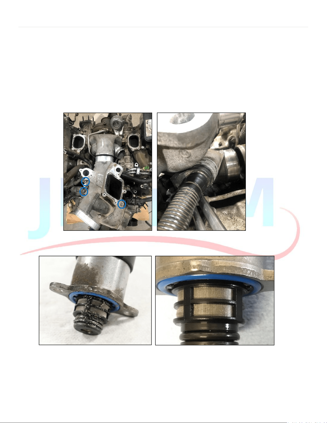
5. Remove the Lower Intake
a. Remove Quantity: 3 bolts, 10mm (refer to Figure 4)
b. Crankcase Breather: Detach the crankcase breather (see Figure 5). This hose may be quite brittle, so handle
with care to avoid damage.
c. Hose Clamps: Loosen the hose clamps securing the intake to the turbocharger.
d. Charge Tube Removal: Use a flat screwdriver to remove the clip and detach the charge tube from the
throttle body assembly.
e. Throttle Body Connection: Disconnect the electrical connection from the throttle body.
Figure 4: Lower Intake Bolts Figure 5: Crankcase Breather
Figure 6: Failing CP4 FCA without Bypass Kit installed Figure 7: Clean FCA
P a g e | 5
JkorkM
5
6. Install the Bypass Block **(For 2020+ see page 7 for specialinstructions)**
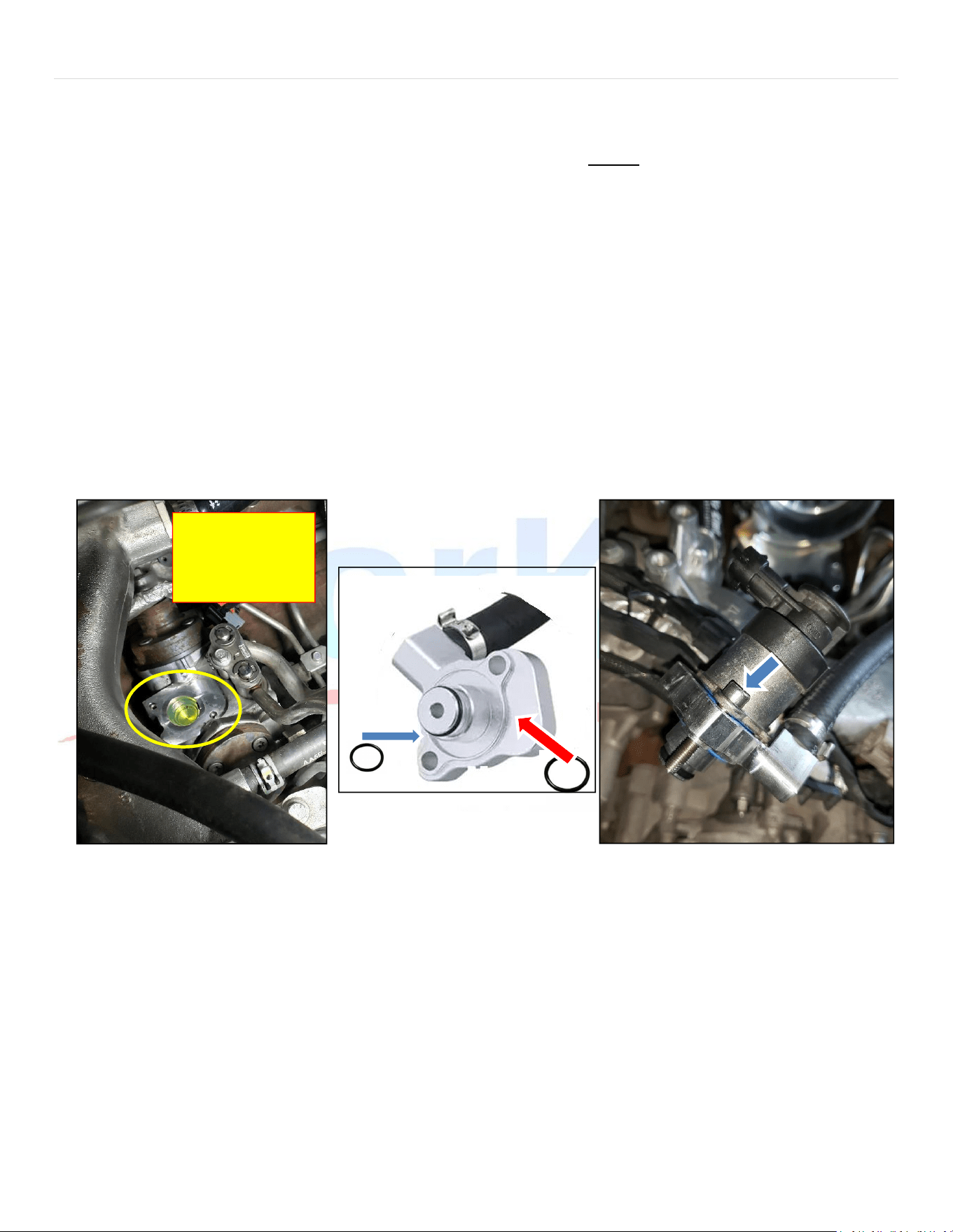
a. You should now have easy access to the Fuel Control Actuator (FCA) on the CP4. Thoroughly clean the
area around the FCA with brake cleaner and compressed air before removing the FCA (Figure 8 ).
i. ENSURE NO DEBRIS ENTERS THE INLET OF THE PUMP WITH THE FCA REMOVED (Figure8).
b. Remove the FCA using a T25 Torx and ensure the pump is healthy by checking the metering unit for
debris (Figure 7 above). If it looks like figure 6, the pump and fuel system must bereplaced.
c. Remove dust covers from the bypass hose assembly quick connects and blow out hoses with
compressed air while being careful to not damage O-rings inside the quick connect fittings. (The hoses
are clean before shipping, but blowing them out again ensures no debris was able to enter the bypass
block passages and hose during transport or handling).
d. Install the large and small O-ring onto the Bypass Block (Figure 9).
e. It is easiest to install the FCA into the bypass block and insert the‘front of truck’ bolt prior to installing
the bypass block into the pump (Figure10).
i. Align the holes and hand thread the ‘rear of truck’ bolt first, then the ‘front of truck’ bolt taking
care not to cross thread the bolts into the fuel pump.
f. Install Bypass Block and FCA onto the CP4 using supplied 4mm Allen head bolts. Torque to 60 inch-lbs.
Figure 8: FCA Removed (no debris) Figure 9: Install O-Rings Figure 10: Subassemble Block, FCA, and front bolt
7. Reinstall the lower intake
a. Torque QTY: 3, 10mm bolts to 18 ft-lb
b. Tighten hose clamps
8. Reinstall the EGR Tube with gaskets in place
a. Torque QTY: 4, 8mm bolts to 89 in-lb
9. Reinstall the upper plastic intake
a. Torque Specification: Tighten 15 pieces of 8mm bolts to 89 in-lb.
b. Install Dipstick Fasteners: Secure the fasteners for the dipsticks.
c. Reconnect Electrical Connections: Re-establish all electrical connections and reinstall the insulation on the
pressure sensor.
d. Wire Routing: Make sure all wires are routed away from hot exhaust components, maintaining the
original layout.
10. Install the fuel filter and housing
Avoid letting
debris enter the
pump inlet!
P a g e | 6
JkorkM
6
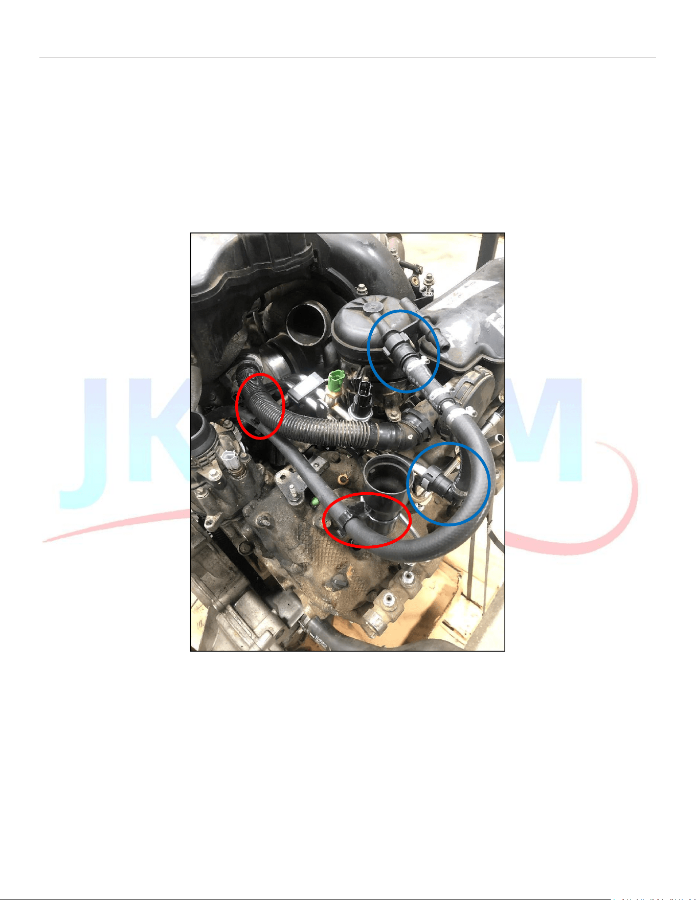
11. Complete bypass kit installation
a. Reattach Crankcase Breather Hose: Secure the crankcase breather hose back onto the lower intake, taking extra care if the hose is
brittle.
b.
Remove Factory Fuel Line: Detach the factory fuel line from the lower hard line.
c.
Take Off Dust Covers: Remove the dust covers from the cleaned bypass kit's quick connect fittings.
d.Connect Quick Connect Fittings: Firmly push the quick connect fittings onto their corresponding barbs (as shown in Figure 11) until
you hear a distinct click. Tug lightly to ensure they are fully seated.
e. Use Zip Tie Hose Clips: Employ the provided zip tie hose clips to prevent the hose from chafing against nearby components (refer to
Figure 11).
i. Use one clip on the crankcase vent and, if necessary, another on the oil filler neck (marked with red circles).
ii. Adjust as needed to ensure the hose does not rub against adjacent components.
Figure 11: Hose Routing & Zip Tie locations
12. Install the hot side compressor outlet to intercooler pipe
P a g e | 7
JkorkM
7
2020+ Special Instructions
Additional parts provided:
- Hose clamp
- Hose and male quick connect assembly
1. Remove the factory plastic line and quick connect assembly
a. For optimal results, it is recommended to remove the factory supply and return line assembly. Use a
heat gun to carefully soften the hose, making it easier to detach from the factory hardline, as illustrated
below.
2. Install the supplied hose and quick connect barb assembly
a. Carefully slide the hose onto the barbs of the factory supply tube, making sure that there is no metal-to-
metal contact between the aluminum fitting and the tube inside the hose.
b. Securely tighten the hose clamp just behind the second barb (see reference image below).
c. Exercise caution to avoid introducing any debris into the system.
d. Install the OEM metal lines along with the adapter assembly.
e. Proceed with the installation as outlined in step 6.
P a g e | 8
JkorkM
8
Gen 2.1 - 6.7L Power Stroke CP4 Return Filter Assembly
CP4-6.7F-BP-G2.1-RFA
2011-2023 Ford Truck – 6.7L Power Stroke Diesel
Installation Instructions
P a g e | 9
JkorkM
9
Recommended Tools
Wrenches:
o 10mm, 7/16”
Deep well Socket
o
15mm
Torque Wrench capable of 120 in-lb (10 ft-lb)
4mm Allen Wrench
Flat Blade Screwdriver
Flush cuts for zip ties
Plastic Fastener Removal Tool
o
Similar to Lisle PN: 35260
Tips & Tricks
Before installation, use compressed air to clean all components to prevent contaminants from entering the fuel system.
Common rail diesel systems are highly sensitive to debris, so it is essential to maintain cleanliness during the installation
process.
If you suspect that the CP4 high-pressure fuel pump has failed after installing the kit, the quickest way to verify this is by
cutting open the Donaldson return fuel filter and checking the filter media for any metal debris. (Model: Longacre 52-
77750)
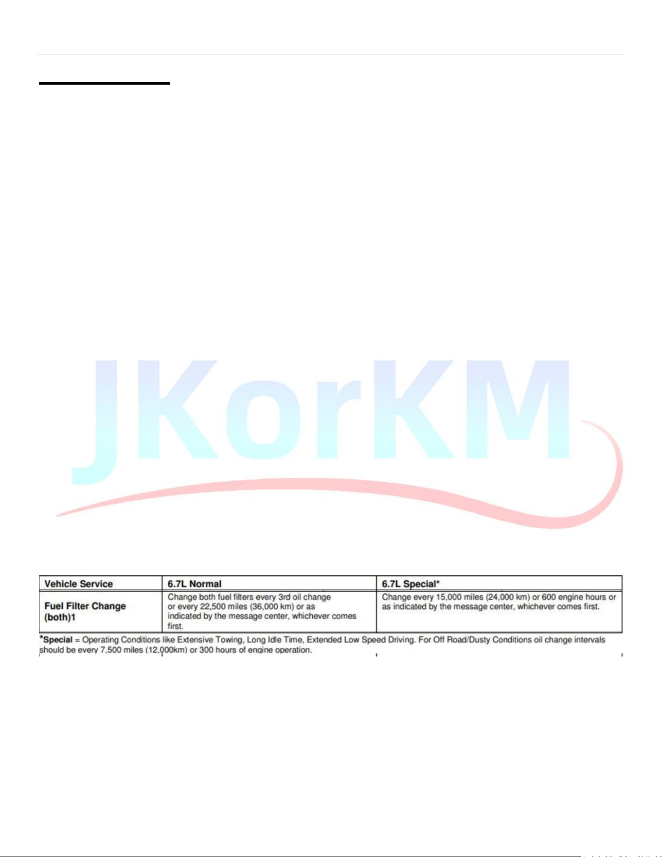
Filter Change Interval:
The filter is designed to be easily serviceable.
o JkorkM Product Number: JM-7031190
o Donaldson Part Number: P550943
The return side fuel filter recommended change interval is the same as the other fuel filters on the vehicle. See
below for the factory Ford filter change recommendations based on duty cycle and operatingconditions.
P a g e | 10
10
Filter Head Assembly
1. O-Ring Installation: Place the small o-rings onto the aluminum filter head fittings, then hand-thread the fittings
into the filter head.
2. Torque Specifications: Using a 15mm deep-well socket, tighten both fittings to a torque of 120 in-lb (10 ft-lb).
Caution: Do not overtighten, as this may lead to damage (refer to Figure 1).
Figure 1: Torque Fittings to 120 in-lb (10 ft-lb) Figure 2: Model Year clarity for bracket to truck
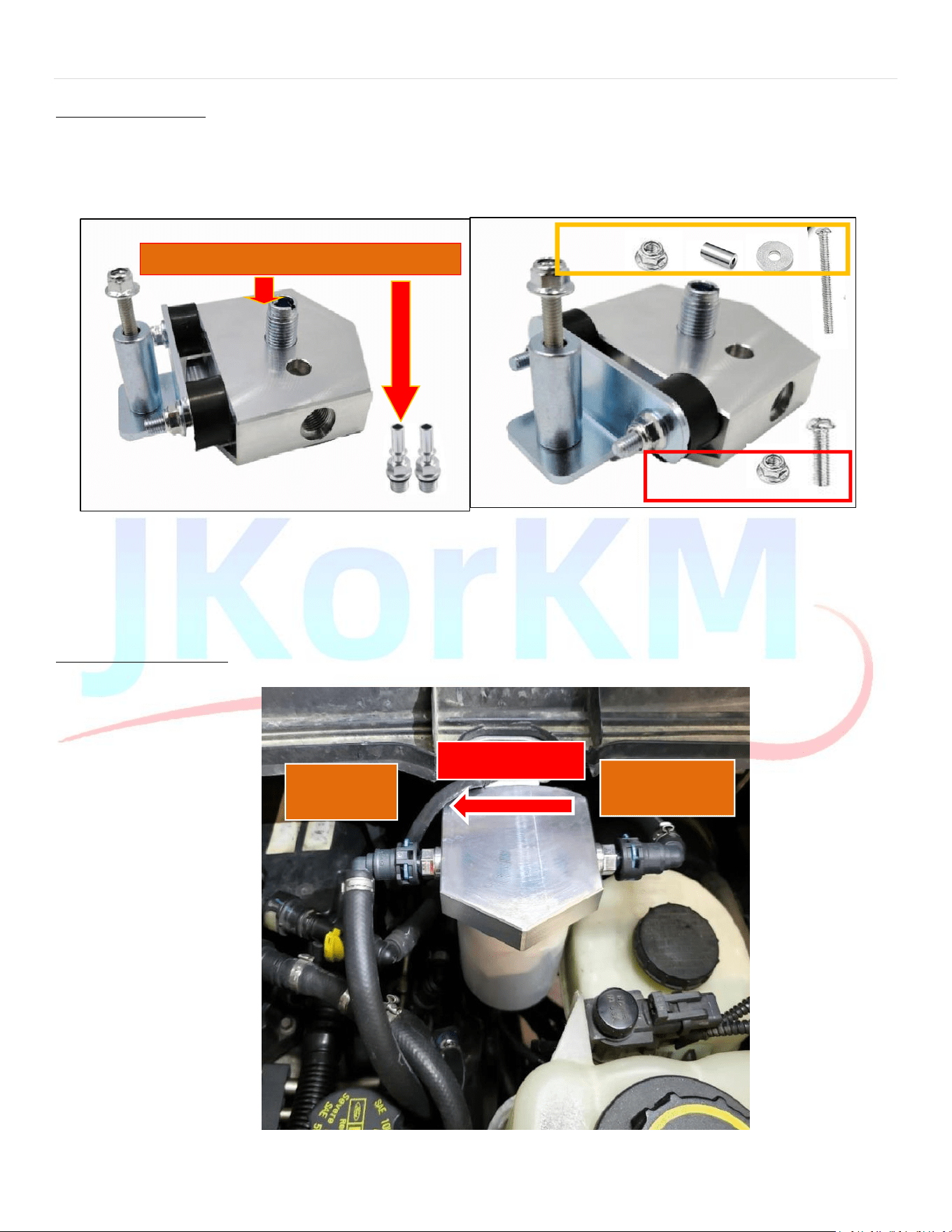
1.Rubber Isolator Installation: Screw the rubber isolators into the back of the filter head until they are hand-tight.
2.Bracket and Nut Assembly: Install the bracket along with the serrated flanged nuts (refer to Figure 2).
a.Use 7/16” wrench to tighten the nuts
Return Hose Installation
1. Filter Flow Diagram
Figure 3: Filter hose orientation and flow direction
Flow Direction
Return Fuel
from Engine
Return Fuel
to Tank
Do not damage these sealing surfaces
2017+
2011-2016
P a g e | 11
11
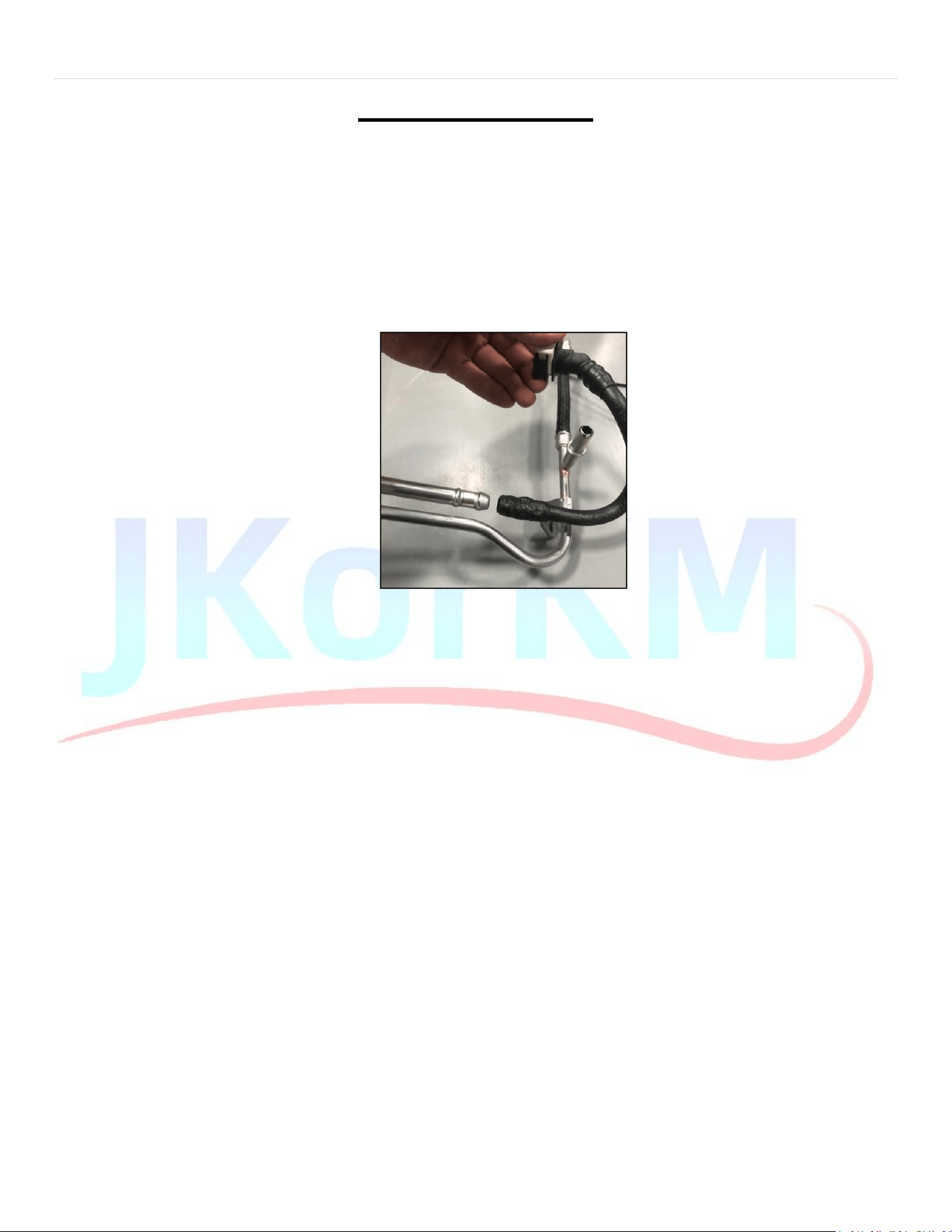
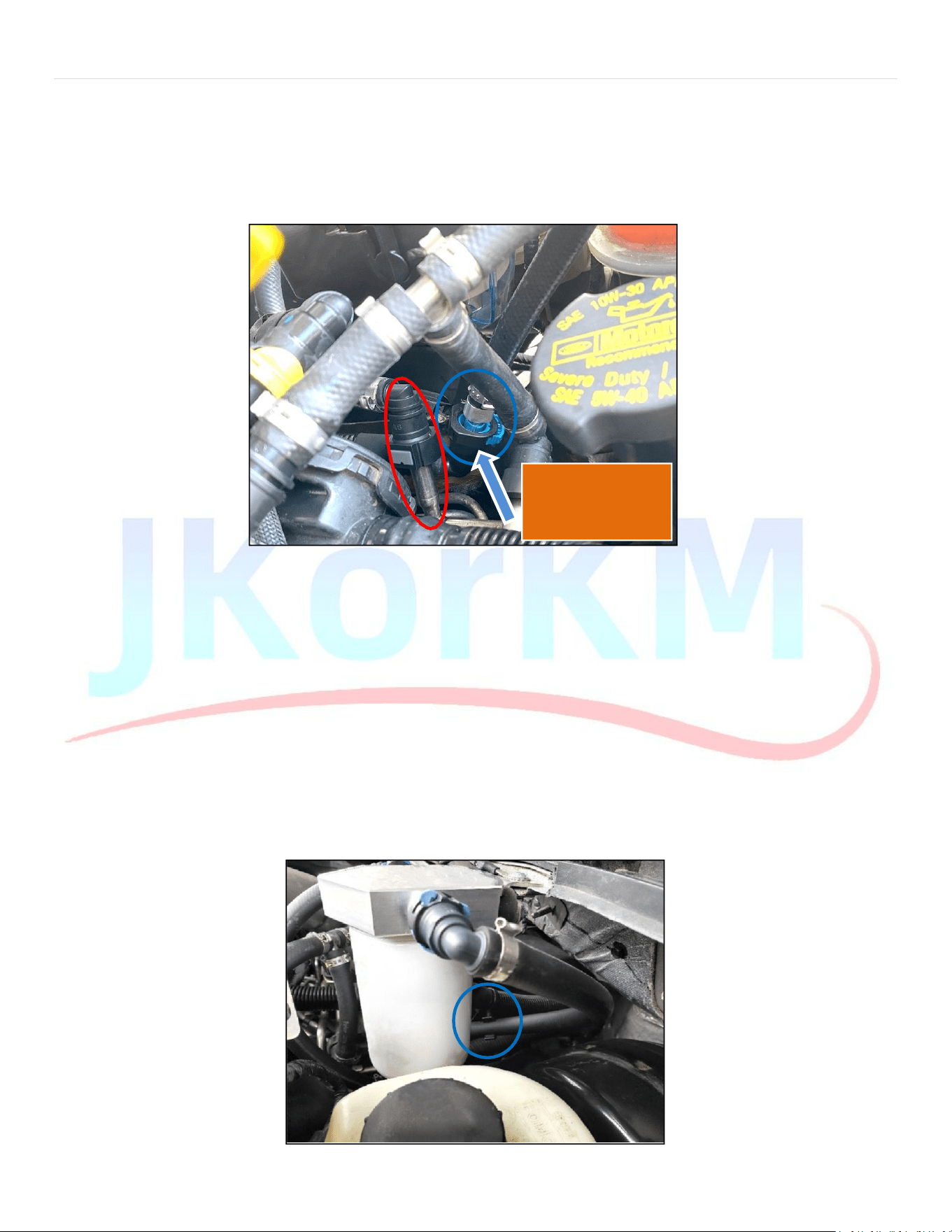
2. Disconnect the return side quick connect and rotate the plastic fitting in the tube to pointupward
a. Position absorbent towels around the joint to catch any spilled diesel fuel.
b. Disconnect the return line quick-connect fitting (highlighted in blue in Figure 4) from the factory metal return
barb (highlighted in red in Figure 4).
c. Grasp the factory plastic line and rotate the plastic female quick-connect fitting inside the molded tube 180° so
that it faces upward. This may require slight adjustments later on.
Plastic OEM
connector
rotated upwards
Figure 4: Quick connect to remove and rotate up (blue circle)
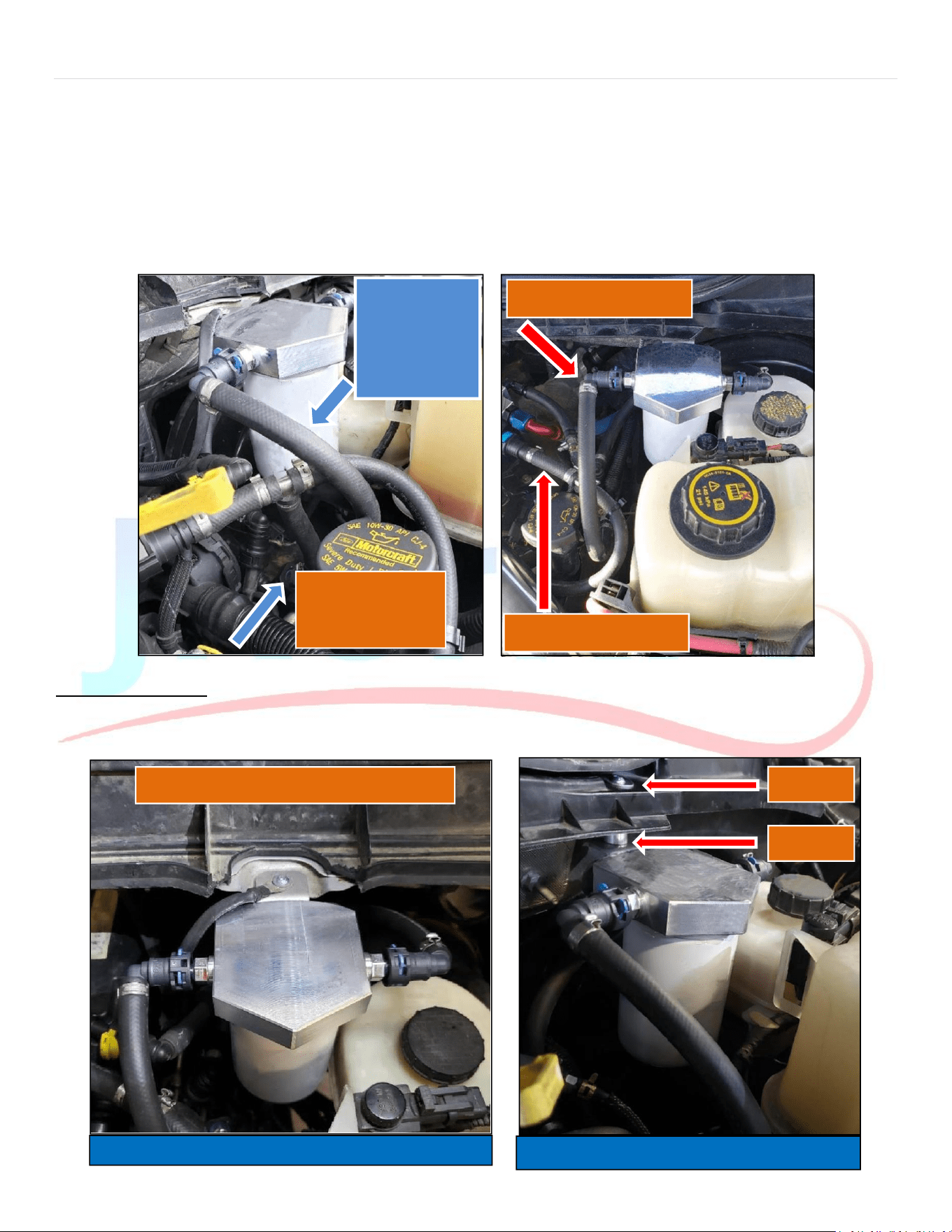
3. Install the JkorkM hose with a plastic connector on both ends(right side of the filter – “Return Fuel from Engine”)
d. Install the Larger Quick Connect: Secure the larger quick-connect fitting onto the OEM metal barb from
which you previously detached the factory fitting (see Figure 4).
e. Route the Hose and Make the Connection: Guide the hose around the back of the filter, then attach the
blue plastic quick-connect fitting to the right side of the filter head, which is designated for return fuel
from the engine.
4. Install the supplied zip tie hose clip
f. Secure the Hose with a Zip Tie: Wrap a zip tie around the factory fuel supply line and fasten the hose to
it. Make any necessary adjustments to ensure the hose remains clear of the brake booster and
reservoir (refer to Figure 5).
Figure 5: Zip tie clip placement
P a g e | 12
12
5. Install the shorter left side hose (left side of the filter – “Return Fuel to Tank”)
g. Insert the Aluminum Barb: Insert the JkorkM aluminum barb into the OEM quick-connect fitting that you
previously disconnected and positioned upward.
h. Connect to the Filter Head: Fasten the opposite end of the aluminum barb to the left side of the filter
head, which is designated for returning fuel to the tank.
i. Finalize the Connection to the Filter Head: Ensure the other end of the aluminum barb is securely
attached to the left side of the filter head, also designated for returning fuel to the tank.
Figure 6: Left Side hose installation Figure 7: Left Side hose installation (2017+)
Filter Head Mounting
The filter head mounting is slightly different between 2011-2016 and 2017+ model years.
2011-2016 2017+
Return hose
from OEM
connector to
left side of
filter head
Plastic OEM
connector
rotated upwards
Use short panhead bolt –
no washer or spacer
Fuel Return to Tank
Washer
Fuel Feed to pump
Spacer
2011-2016 model years
2017+ model years
P a g e | 13
13
2011-2016 Model Years
1. Remove the Ground Strap Bolt: Detach the bolt that secures the ground strap to the upper firewall/cowl
located above the brake fluid reservoir.
2. Install the Filter Head Bracket: Position the filter head bracket on top of the metal cowl. Place the ground
strap on top of the bracket and secure it using the provided short panhead bolt.
a. Tighten the Bolt: Use a 4mm Allen wrench to tighten the bolt into the factory threaded hole for the
ground strap.
3. Attach the Fuel Filter to the Filter Head:
a. Lubricate the O-Ring: Apply a thin layer of motor oil, diesel fuel, or a similar lubricant to the O-ring of the
fuel filter.
b. Install the Filter: Screw the filter onto the filter head until the rubber seal makes contact, then turn an
additional half turn by hand to ensure a tight fit.
4. Purge Air and Check for Leaks:
a. Cycle the Key: Turn the key to the accessory position, allowing the electric fuel pump to run for 30
seconds to purge any air before starting the engine.
b. b. Start the Engine: Once the engine is running, inspect for any leaks around the filter and connections
2017+ Model Years
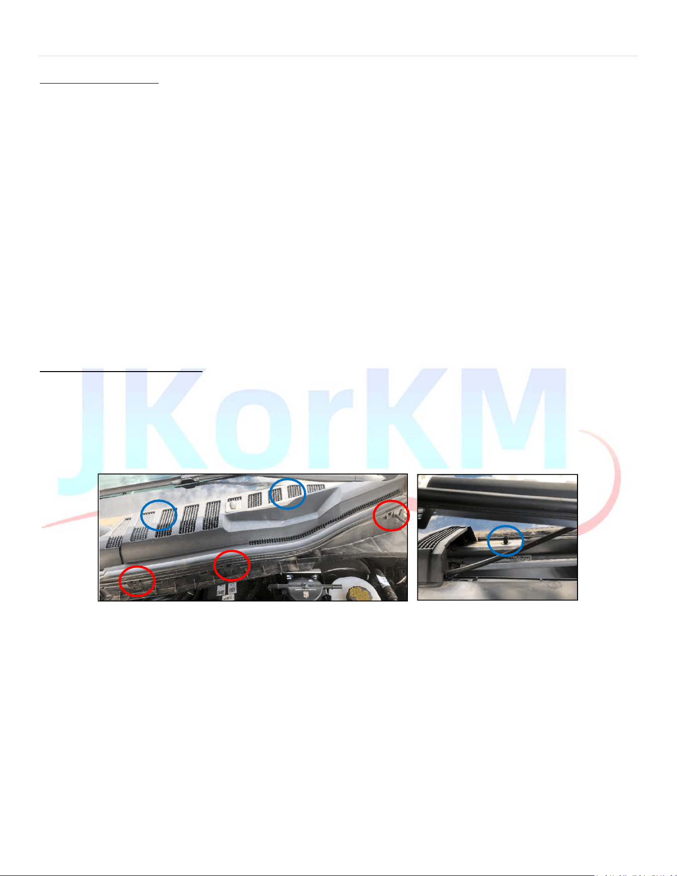
1. Loosen the cowl to access the hole for installing the fuel filter.
a. Detach the Clips: Carefully release the three clips located at the front (marked by the red circle) and
the two clips underneath (near the blue circles). Gently wiggle and pry up on the cowl to detach them
(see Figure 8).
b. If you break a clip (Figure 9) the part number is: W708771-S300
Figure 8: Clip Locations Figure 9: Clip under the cowl x2
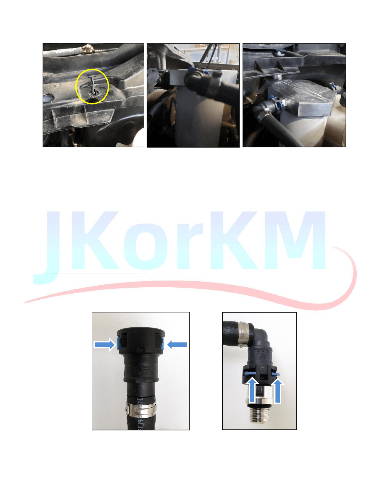
2. Remove the plastic fastener from cowl (Figure 10).
3. Install the provided long filter bracket bolt and washer through thishole.
a. Prepare the Washer: Place the washer onto the long bolt.
b. Assemble the Components: Insert the provided long bolt through the designated hole, then add the
spacer, followed by the filter bracket (refer to Figure 12).
P a g e | 14
14
c. Tighten the provided nylon lock nut with 10mm wrench (nut) and 4mm Allen wrench(bolt).
Figure 10: Remove plastic fastener Figure 11: Spacer below cowl Figure 12: Filter Head Installed – 2017+
4. Install fuel filter to filter head.
a. Lubricate the O-Ring: Apply a thin layer of motor oil, diesel fuel, or a suitable lubricant to the O-ring of the
filter.
b. Spin the filter on until the rubber seal makes contact with the filter head, then rotate it an additional half
turn.
5. Purge air and check for leaks.
c. Prime the Fuel System: Turn the key to the accessory position and allow the electric fuel pump to
run for 30 seconds. This will help purge any air from the system before starting the engine.
d. Start the Engine: Start the engine and carefully check for any signs of leaks.
Quick Connect Removal Guide
Quick Connect Style #1 – Push-Button: Disconnect the Connector: To release it, firmly press the buttons and gently pull the
connector away. (See Figure 1).
Quick Connect Style #2 – Locking Tabs: Release the Locking Tabs: To disengage the locking tabs on the quick-connect fittings
of the filter head, slide both tabs away from the filter head and press them downward toward the male fitting. This action will
unlock the connector, allowing it to be removed from the filter head fitting (refer to Figure 2).
Figure 1: Push-Button QC Figure 2: Locking Tab QC
P a g e | 15
15
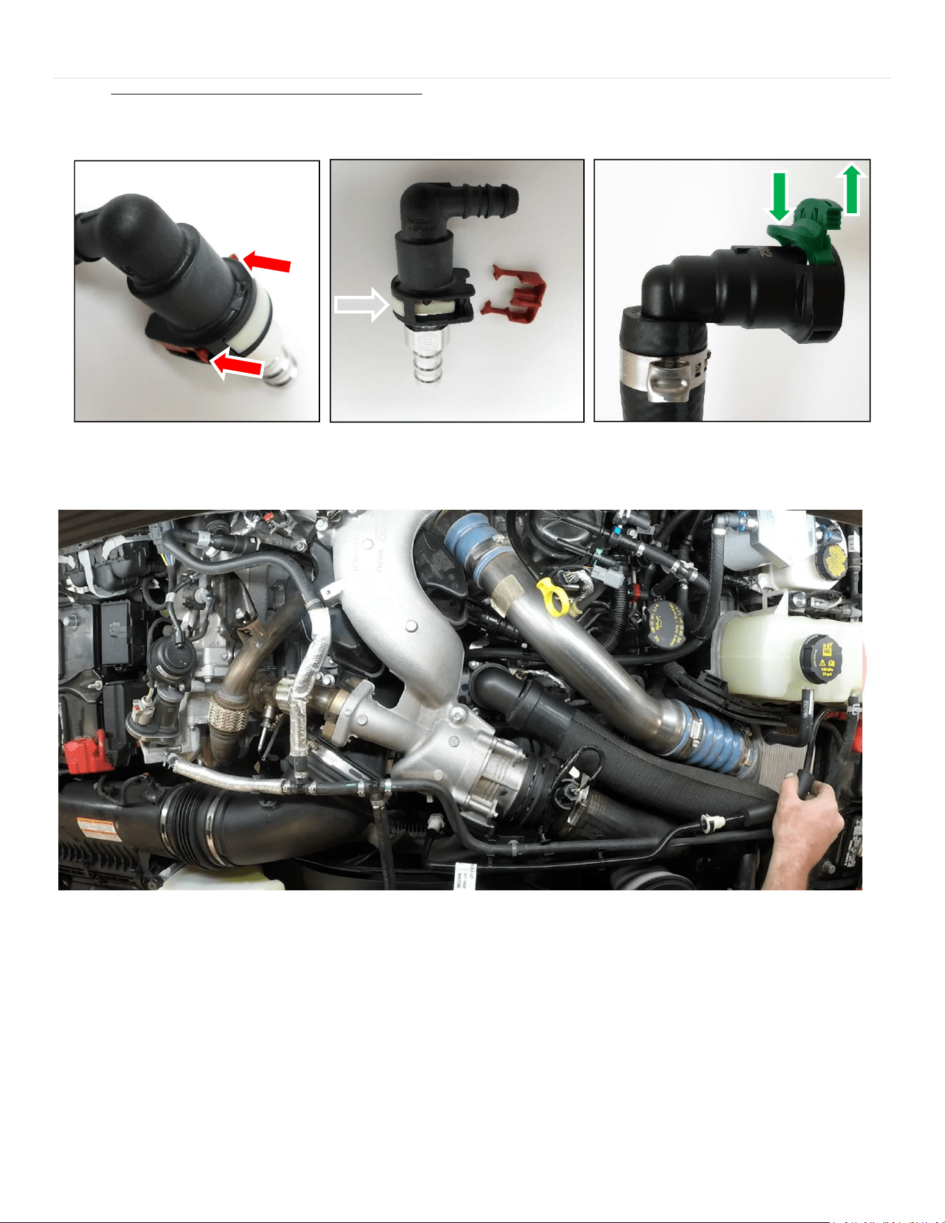
Quick Connect Style #3 – Lock plus Push-Button: Unlocking the Connector: To release the lock, pull the red tabs away
from the connector and press down until the lock reaches its lowest position, or completely remove the lock as
illustrated. After the lock is disengaged, press the button firmly and pull the connector off the fitting (see Figure 3). For
the green connector, simply lift the lock upward and then press down on the button (refer to Figure 4).
Figure 3: RED Lock + Push-Button QC – 2-step process Figure 4: GREEN Lock + Push-Button QC
Complete top view