08/2026
Read these instructions carefully before using your appliance, and keep it carefully.
If you follow the instructions, your appliance will provide you with many years of good service.
INSTRUCTION MANUAL
ENGLISH
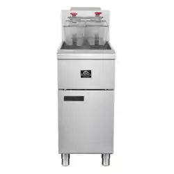
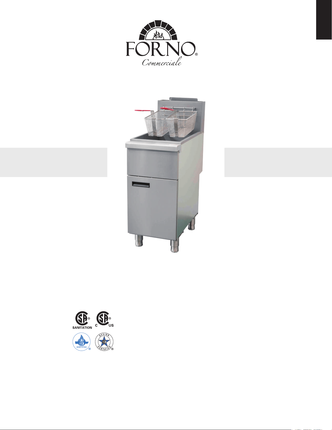
FORNO COMMERCIAL GAS DEEP FRYER, 3-BURNER Liquid Propane Gas
FCMGF0016
ANSI Z83.11 • CSA 1.8-(2016) Food Service Equip.
Conforms to ANSI STD Z83.11-2016
Certified to CSA STD 1.8-2016 Food Service Equip.
CONFORMS TO NSF/ANSI 4:2020

TABLE OF CONTENTS
Customer Care 4
Warning 5
Product Dimension 7
Installation 8
Operation 15
Cooking Hints and Cleaning
Service
Warranty
17
19
23
4
Thank you for purchasing a Forno product. Please read the entire instruction manual before operating your new appliance
practices, features, operation and care recommendations of your appliance.
Both the model and serial number are listed inside the product. For warranty purposes, you will also need the date of
purchase .
Record this information below for future reference.
Services in Canada and Untied States
Keep the instruction manual handy to answer your questions. If you don’t understand something or need more assistance,
please visit our website for fast support. Please provide us your name, number, address,serial number of the product that
troubleshooting, proof of purchase, and a short description of the issue. A customer service representative will contact you
providers are carefully selected and rigorously trained by us.
Product Information Service Information
Model Number : _________________________________________
Use these numbers in any
correspondence or services calls
concerning your product.
If you received a damaged product,
immediately contact Forno.
To save time and money, before
you call for serviced, check the
troubleshooting guide. It listed the
causes of minor operation problems
that you can correct yourself.
Serial Number :
Date of Purchase :________________________________________
Purchase Address And Phone : _____________________________
_______________________________________________________
_______________________________________________________
Customer Care
“Need some quick help? Simply scan the qr code and get access
to our fast support form. We’re always here to assist you with any
questions or concerns you may have. So, don’t hesitate to reach out!”
5
WARNING
FOR YOUR SAFETY
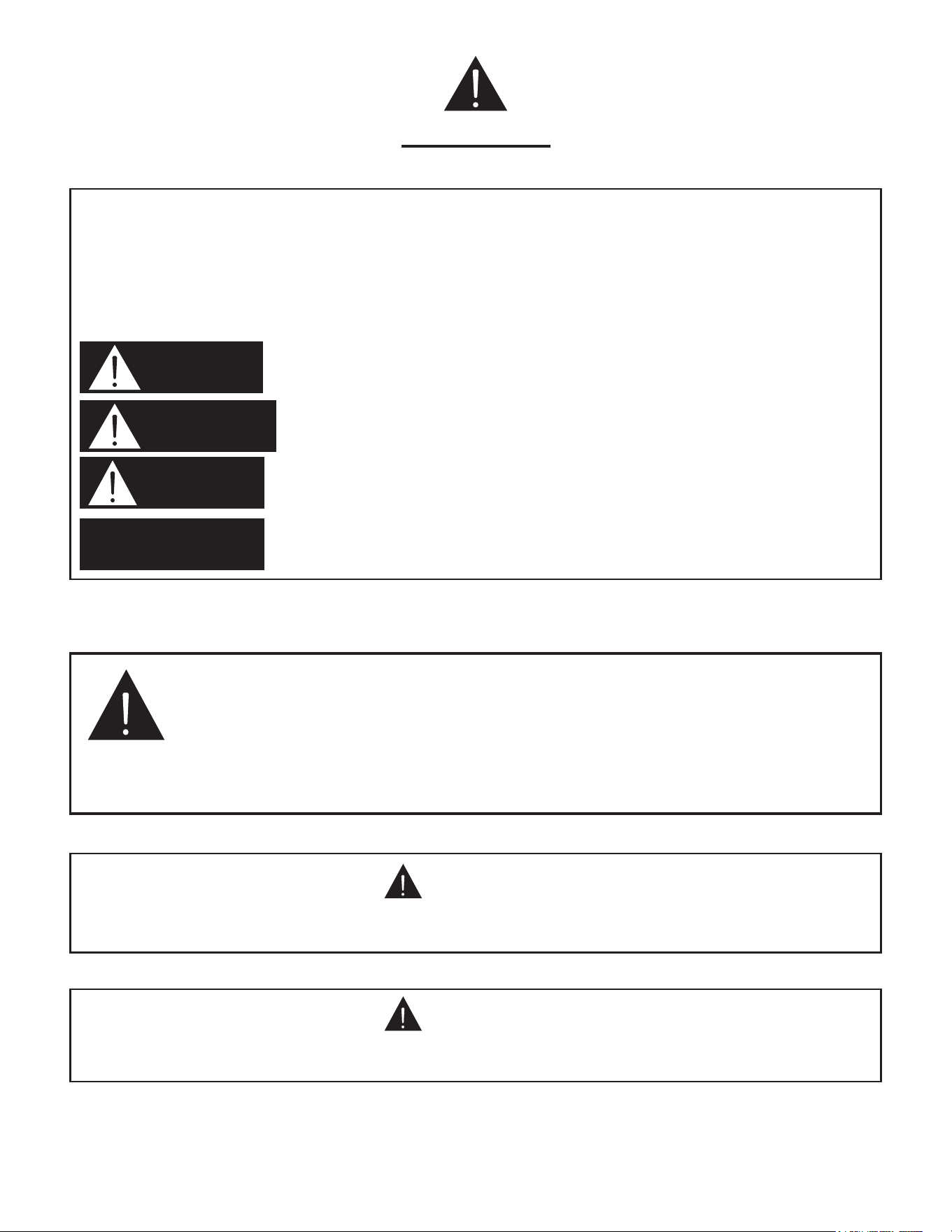
This symbol warns of immediate hazards that will result in severe injury or death.
This symbol refers to a potential hazard or unsafe practice that could result in injury
or death.
This symbol refers to a potential hazard or unsafe practice that could result in injury,
product damage, or property damage.
This symbol refers to information that needs special attention or must be fully
understood, even though not dangerous.
DANGER
WARNING
CAUTION
NOTICE
BURN Hazard
WARNING
Before installing and operating this equipment, be sure everyone involved in its operation is
fully trained and aware of precautions. Accidents and problems can be caused by failure to
follow fundamental rules and precautions.
The following symbols, found throughout this manual, alert you to potentially dangerous
conditions to the operator, service personnel, or to the equipment.
WARNING
Fire Hazard
FOR YOUR SAFETY
Do not store or use gasoline or other flammable vapors and liquids in the vicinity
of this or any other appliance.
Keep area around appliances free and clear of combustibles.
Purchaser of equipment must post in a prominent location, detailed instructions
to be followed in the event the operator smells gas. Obtain the instructions from
the local gas supplier..
Contact with hot oil will cause severe burns. Always use caution. Oil at 200F is more danger-
ous than boiling water.
In the event a gas odor is detected, shut down equipment at the combination gas valve and
contact the local gas company or gas supplier for service.
Congratulations! You have purchased one of the finest pieces of commercial cooking equipment on the
market.
You will find that your new equipment, has been designed and manufactured to meet the toughest standards
in the industry. Each equipment is carefully engineered and designs are verified through laboratory tests and
field installations. With proper care and field maintenance, you will experience years of reliable, trouble-free
operation. For best results, read this manual carefully.
RETAIN THIS MANUAL FOR FUTURE REFERENCE.
This manual is for Gas floor model Fryers with 40 lbs capacity frypot.
For gas floor model fryers, The recommended oil capacity minimum 32 lbs,maximum 40 lbs.
Read these instructions carefully before attempting installation. Installation and initial startup should be
performed by a qualified installer. Unless the installation instructions for this product are followed by a
qualified service technician (a person experienced in and knowledgeable with the installation of commercial
gas and/or electric cooking equipment) then the terms and conditions on the Manufacturer’s Limited
Warranty will be rendered void and no warranty of any kind shall apply.
6
WARNING
FOR YOUR SAFETY
NOTICE
NOTICE
Gas floor model fryers are intended for commercial use only. Not for household use.
Warranty will be void if service work is performed by other than a qualified technician, or if other
than genuine replacement parts are installed.
Be sure this Operator’s Manual and important papers are given to the proper authority to retain
for future reference.
7
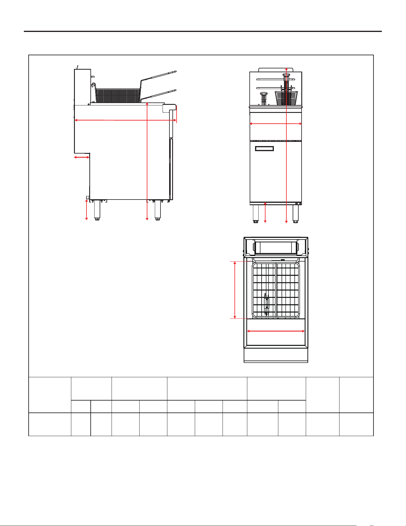
Product Dimension
Note: for mm, multiply inches by 25.4
Model
Width (in) Depth (in) Height (in) Gas Connection
(in)
Total
BTU/hr
Crated
Weight
(lbs)
A B C D E F G H I
3 burners
fryer
15.5 14.0 30.3 13.8 45.5 34.7 6.0 4.2 7.0 90,000 125
E
A
G
B
D
F
H
I
C
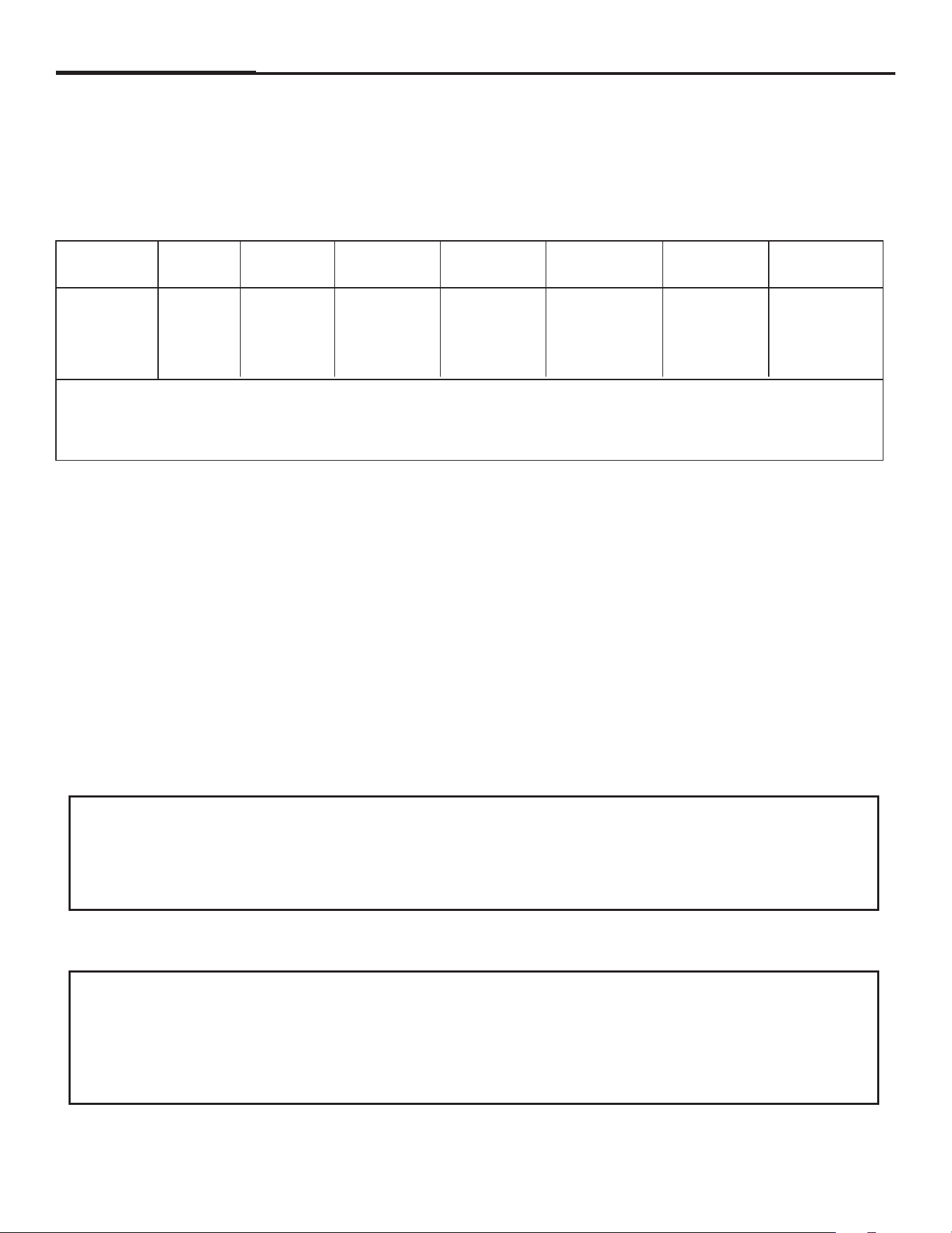
Supply pressure should be minimum of 4" W.C. for natural gas or 10" W.C. for liquid propane. The fryer comes
with ¾” NPT male connector on a ½” pipe, allowing you to connect with either ¾” or ½” NPT female connector.
8
INSTALLATION
INSTALLATION
NOTICE
Installation must conform with local codes, or in the absence of local codes, with the National Fuel Gas
Code, ANSI Z223.1, Natural Gas Installation Code, CAN/CGA-B149.1, or the Propane Installation Code,
CAN/CGA-B149.2, as applicable.
NOTICE
These installation procedures must be followed by qualified personnel or warranty will be void.
Local codes regarding installation vary greatly from one area to another. The National Fire Protection
Association, Inc. states in its NFPA 96 latest edition that local codes are the “authority having jurisdiction”
when it comes to installation requirements for equipment.
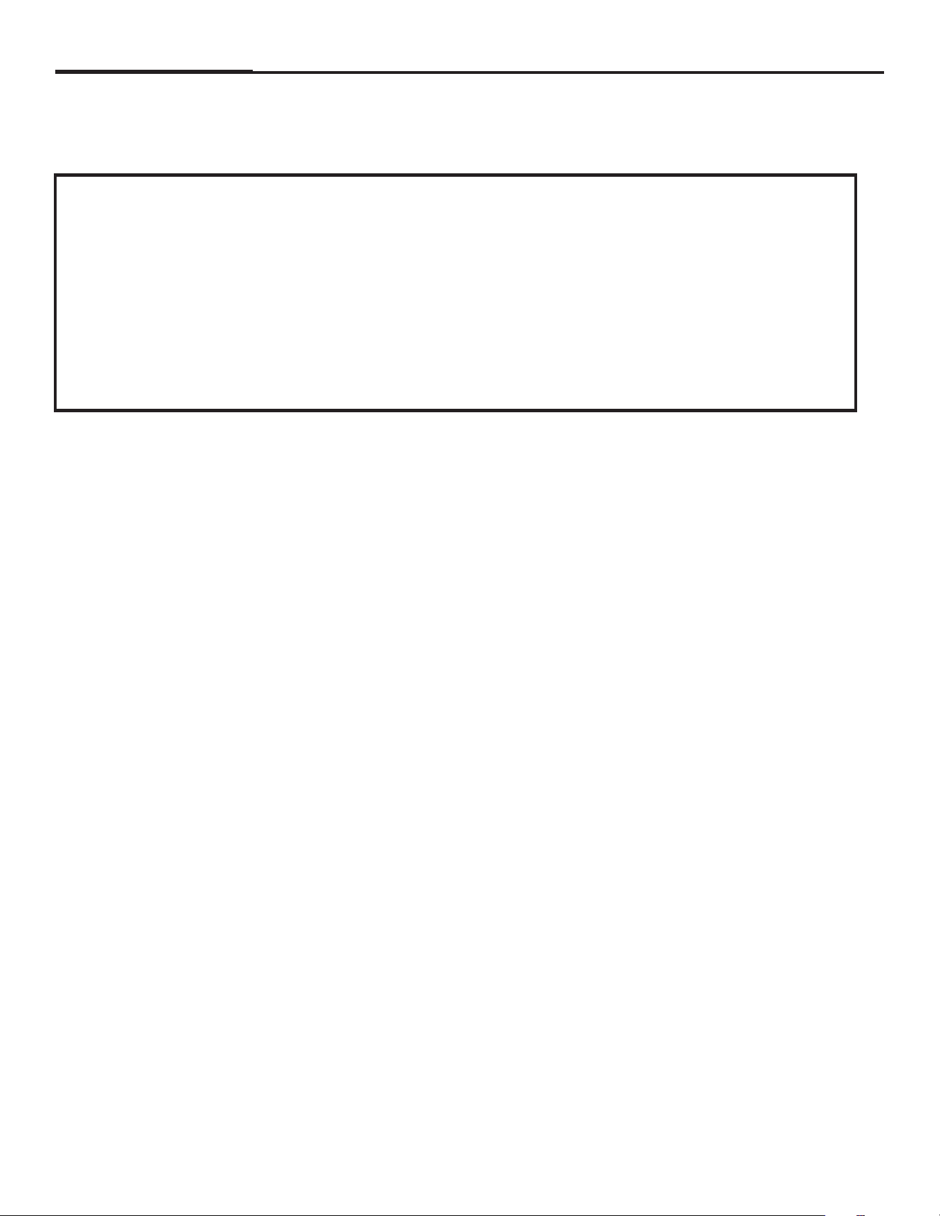
Model
Burners
Gas Type
Liquid
Propane
10”W.C.
3
30,000 90,000 #52
3 burners
fryer LP
Main
Manifold
Pressure
*Minimum supply pressure is 4" W.C. for natural gas and 10" W.C. for liquid propane.
** Orifice sizes are for units installed at altitudes between 0 and 3499 feet above sea level
Number of
hert tube
Rate Each
BTUs/Hour
Total Rate
BTUs/Hour
Orifice Size
9
INSTALLATION(continued)
Step 1: Unpack
Step 2: INSTALL THE LEGS (OR OPTIONAL CASTERS) AND RESTRAINTS
IMMEDIATELY INSPECT FOR SHIPPING DAMAGE
All containers should be examined for damage before and during unloading. The freight carrier has
assumed responsibility for safe transit and delivery. If damaged equipment is received, either
apparent or concealed, a claim must be made with the delivering carrier.
Apparent damage or loss must be noted on the freight bill at the time of delivery. The freight bill must
then be signed by the carrier representative (Driver). If the bill is not signed, the carrier may refuse
the claim. The carrier can supply the necessary forms.
A request for inspection must be made to the carrier within 15 days if there is concealed damage or
loss that is not apparent until after the equipment is uncrated. The carrier should arrange an
inspection. Be certain to hold all contents plus all packing material.
A set of legs is packed with the fryer. Casters are optional, purchased separately. Mounting fasteners are
pre-mounted on the base plates.
1. Raise fryer sufficiently to allow legs or casters to be screwed into the base plate. For safety, “shore up”
and support the fryer with an adequate blocking arrangement strong enough to support the load.
2. Screw the four legs or casters to the plate on the bottom of the fryer. When casters have been ordered,
the casters having a locking-brake should be attached under the front of the fryer.
3. Lower the fryer gently. Never drop or allow the fryer to fall.
4. Use a level to make sure that the fryer is level. Each caster, or the tubular-end of each leg, can be
screwed in or out to lower or raise each corner of the fryer.
5. Attach restraints as required by local codes.
6. Raise fryer sufficiently to allow legs or casters to be screwed into the base plate. For safety, “shore up”
and support the fryer with an adequate blocking arrangement strong enough to support the load.
7. Screw the four legs or casters to the plate on the bottom of the fryer. When casters have been ordered,
the casters having a locking-brake should be attached under the front of the fryer.
8. Lower the fryer gently. Never drop or allow the fryer to fall.
9. Use a level to make sure that the fryer is level. Each caster, or the tubular-end of each leg, can be
screwed in or out to lower or raise each corner of the fryer.
10. Attach restraints as required by local codes.
1. Uncrate carefully. Report any hidden damage to the freight carrier IMMEDIATELY.
2. Do not remove any tags or labels until unit is installed and working properly.
10
INSTALLATION (continued)
NOTICE
Unit must be level to assure maximum performance. Improper leveling may void warranty.
NOTICE
When this appliance is installed with casters, it must be installed with the casters supplied, a
connector complying with either ANSI Z21.69 CSA 6.16 and a quick-disconnect device complying
with ANSI Z21.41 CSA 6.9. It must also be installed with restraining means to guard against
transmission of strain to the connector, as specified in the appliance manufacturer instructions.
When this appliance is installed with casters, it must be installed with the casters supplied, a
connector complying with either ANSI Z21.69 or CAN/CGA-6.16 and a quick disconnect device
complying with either ANSI Z21.41 or CAN1-6.9. It must also be installed with restraining means to
guard against transmission of strain to the connector, as specified in the appliance manufacturer's
instructions.
WARNING
All fryers must be restrained to prevent tipping in order to avoid the splashing of hot liquid. The means
of restraint may be the manner of installation.
WARNING
If disconnection of the restraint is necessary to move the appliance for cleaning, etc.,
reconnect it when the appliance is moved to its original installed position.the ignition
source.
WARNING
WARNING
This product can expose you to chemicals including [Lead & Lead Compounds], which is [are] known
to the State of California to cause cancer, birth defects and / or reproductive harm. To minimize
exposure to these substances. Always operate this unit according the Owner’s Manual, and ensure
that you provide proper ventilation. For more information go to www.P65Warnings.ca.gov
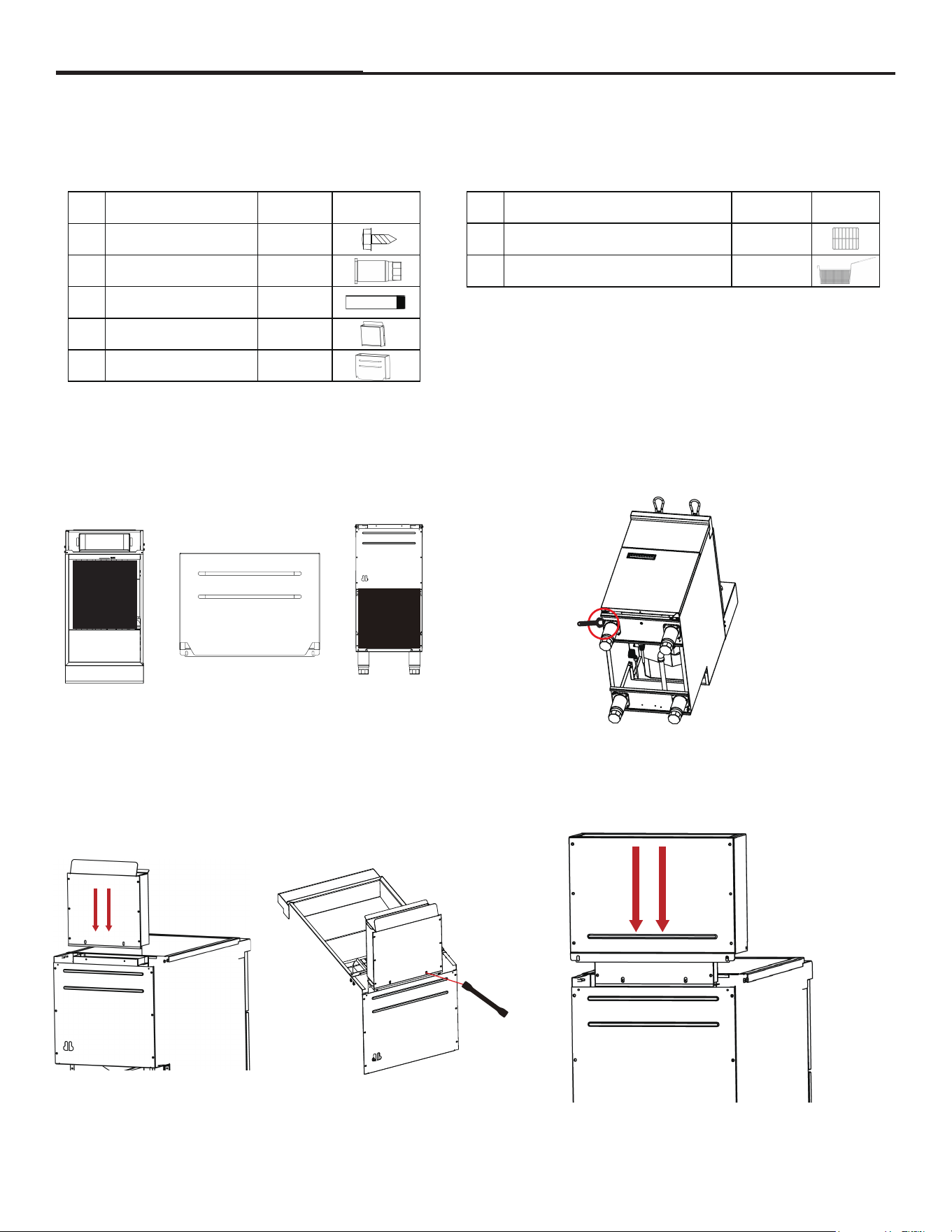
Step 3: Flue installation
11
INSTALLATION (continued)
3.Slide the inner flue box into frypot flue,and secure it
with the two self-tapping screws by a 5/16" socket
4.Slide the outer flue box into the
inner flue box
No.
1
2
3
4
5
Accessory
Screw
Leg
Drain extension
Inner flue box
Outer flue box
Accessory
Screen
Basket
Q'TY
10
4
1
1
1
Fig
No.
6
7
Q'TY
1
2
Fig
1.Unpack the Inner flue box and Outer flue box
lnner flue box
and Outer flue box
Outer flue box
Tank back
panel here
2.Locate the four adjusting feet and the fixing
screws and nuts. Use a wrench or socket to
tighten them from below,Level the equipment.
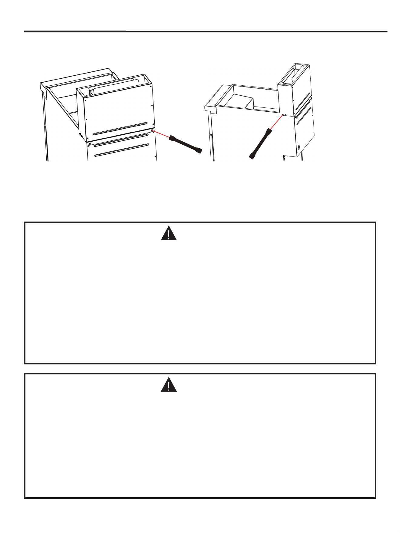
12
INSTALLATION (continued)
Step 4:Check Clearances and Ventilation
There must be adeguate clearance between fryer(s) and construction. Clearance must also be
provided in front for servicing and for operation.
Minimum Clearances:
From Combustible Construction
Sides 6 inches
Rear 6 inches
WARNING
ALL GAS FLOOR MODEL FRYERS SHALL BE INSTALLED WITH AT LEAST A 16 INCH SPACEBETWEEN THE
FRYER AND SURFACE FLAMES FROM ADJACENT EQUIPMENT. A FLAMEGUARD IS ACCEPTABLE IF
ALLOWED UNDER LOCAL CODE.
No additional side and rear clearance is required for service as the fryer is serviceable from the front.
Improper ventilation can result in personal injury or death. Ventilation that fails to prop-
erly remove flueproducts can cause headaches, drowsiness, nausea, or could result in
death.
Unit Must be installed under a ventilation hood
All units must be installed in such a manner that the flow of combustion and ventilation
air is notobstructed. Provisions for adequate air supply must also be provided. Do NOT
obstruct the bottomfront of the unit, as combustion air enters through this area. Be sure
to inspect and clean theventilation system according to the ventilation equipment manu-
facturer's instructions.
WARNING
5.Secure it with four self-tapping screws two on the back and one on each side using a 5/16" socket

Step 5: Gas connection
13
INSTALLATION (continued)
Due to the variety of problems that can be caused by outside weather conditions, venting by canopies or wall
fans is preferred over any type of direct venting. It is recommended that a canopy extend 6" past the appliance
and the bottom edge be located 6'6" from the floor. Filters should be installed at an angle of 45° or more from
the horizontal. This position prevents dripping of grease and facilitates collecting the run-off grease in a drip
pan, unusually installed with a filter. A strong exhaust fan tends to create a vacuum in the room and may
interfere with burner performance or may extinguish pilot flames. Fresh air openings
approximately equal to the fan area will relieve such a vacuum. In case of unsatisfactory performance on any
appliance, check the appliance with the exhaust fan in the “OFF” position. Do this only long enough to check
equipment performance, then turn hood back on and let it run to remove any exhaust that may have accumu-
lated during the test.
A 3/4" male NPT line for the gas connection is located near the lower right rear corner of the fryer. The serial plate
(located inside the front door of the fryer) indicates the type of gas the unit is equipped to burn (natural gas or
propane). The fryer should be connected ONLY to the type of gas for which it is equipped.
A circuit diagram is located inside the front door of the fryer.
This equipment is adjusted at the factory; however, pilot height should be checked at installation and adjusted, if
necessary.
For orifice sizes and pressure regulator settings, see the chart on page 4. If the fryer is being installed at over2,000
feet altitude and that information was not specified when ordered, contact the appropriate authorized Service
Representative or the Service Department. Failure to install with proper orifice sizing will result in poor performance
and may void the warranty.
If applicable, the vent line from the gas appliance pressure regulator shall be installed to the outdoors inaccordance
with local codes or, in the absence of local codes, with the National Fuel Gas Code, ANSI Z223.1, Natural Gas
Installation Code, CAN/CGA-B149.1, or the Propane Installation Code, CAN/CGAB149.2, as applicable.
An adequate gas supply is imperative. Undersized or low pressure lines will restrict the volume of gas necessary
for satisfactory performance. A combination gas valve and pressure regulator, which is provided with each unit, is
set to maintain a 4" W.C. manifold pressure for natural gas or 10.0" W.C. manifold pressure for propane gas.
However, to maintain these conditions the pressure on the supply line, when all units are operating simultaneously,
should not drop below 7" W.C. for natural gas or 11" W.C. for propane gas. Fluctuations of more than 25% on
natural gas or 10% on propane gas will create problems and affect burner operating characteristics. A 1/8" tap to
measure the manifold pressure is located on the combination gas
valve, which is on the burner manifold located directly below the burners inside the cabinet.
Purge the supply line to clean out dust, dirt, or other foreign matter before connecting the line to the unit.
It is recommended that an individual manual shutoff valve be installed in the gas supply line to the unit.
Use pipe joint compound that is suitable for use with both natural and LP gas on all threaded connections.
The exhaust fan should be installed at least 2 feet above the vent opening at the top of the fryer.
Make sure all ventilation meet local code requirement
This unit is not intended to be connected directly to an outside flue.
14
INSTALLATION (continued)
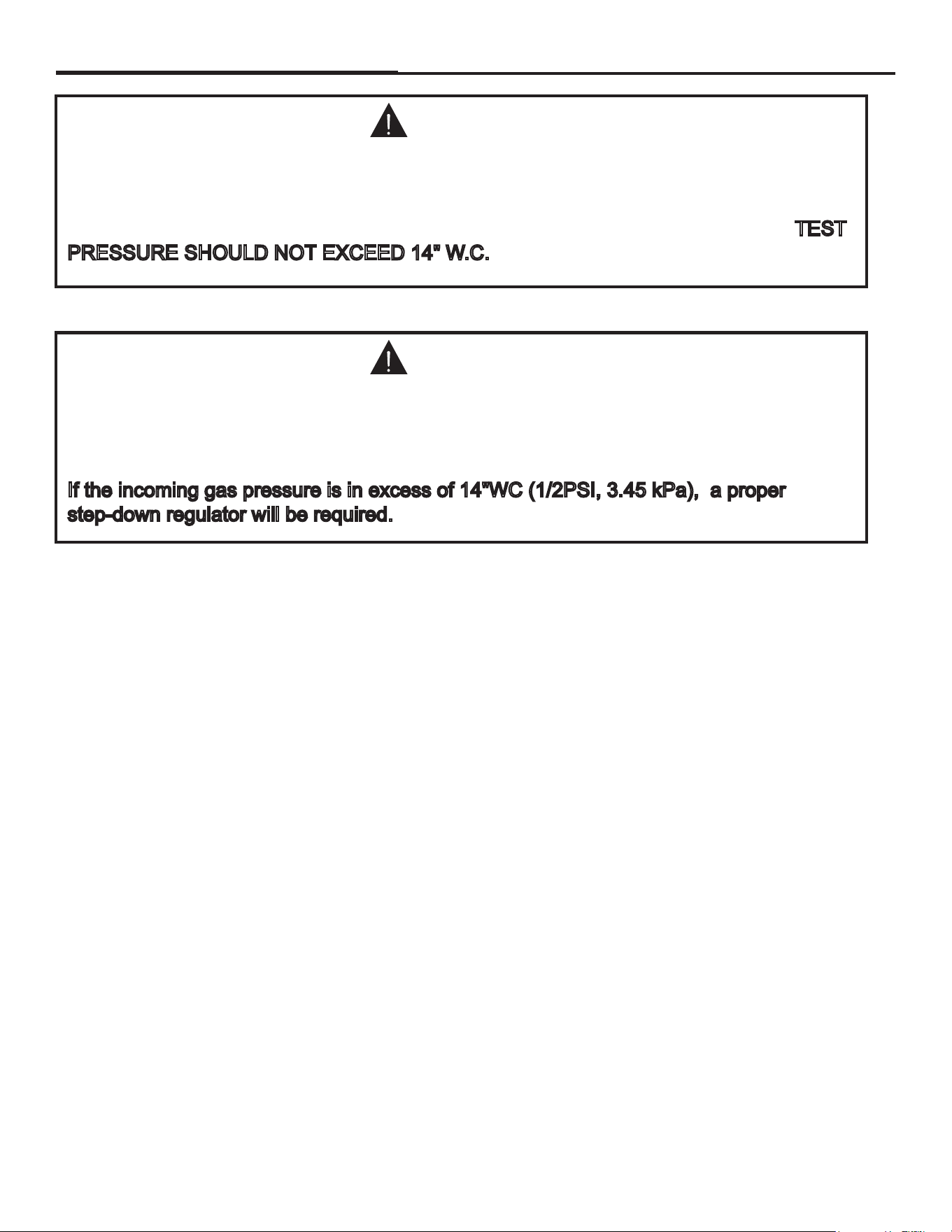
ALL PIPE JOINTS AND CONNECTIONS MUST BE TESTED THOROUGHLY FOR
GAS LEAKS. USE ONLY SOAPY WATER FOR TESTING ON ALL GASES. NEVER
USE AN OPEN FLAME TO CHECK FOR GAS LEAKS. ALL CONNECTIONS MUST BE
CHECKED FOR LEAKS AFTER THE UNIT HAS BEEN PUT INTO OPERATION. TEST
PRESSURE SHOULD NOT EXCEED 14" W.C.
CAUTION
THIS APPLIANCE AND ITS INDIVIDUAL COMBINATION GAS VALVE MUST BE DIS-
CONNECTED FROM THE GAS SUPPLY PIPING SYSTEM DURING ANY PRESSURE
TESTING OF THAT SYSTEM AT TEST PRESSURES IN EXCESS OF 14”WC (1/2
PSIG or 3.45 kPa).
If the incoming gas pressure is in excess of 14"WC (1/2PSI, 3.45 kPa), a proper
step-down regulator will be required.
CAUTION
OPERATION
15
OPERATION
LIGHTING
Open the burner compartment door and do the following:
1. Turn thermostat to “OFF”
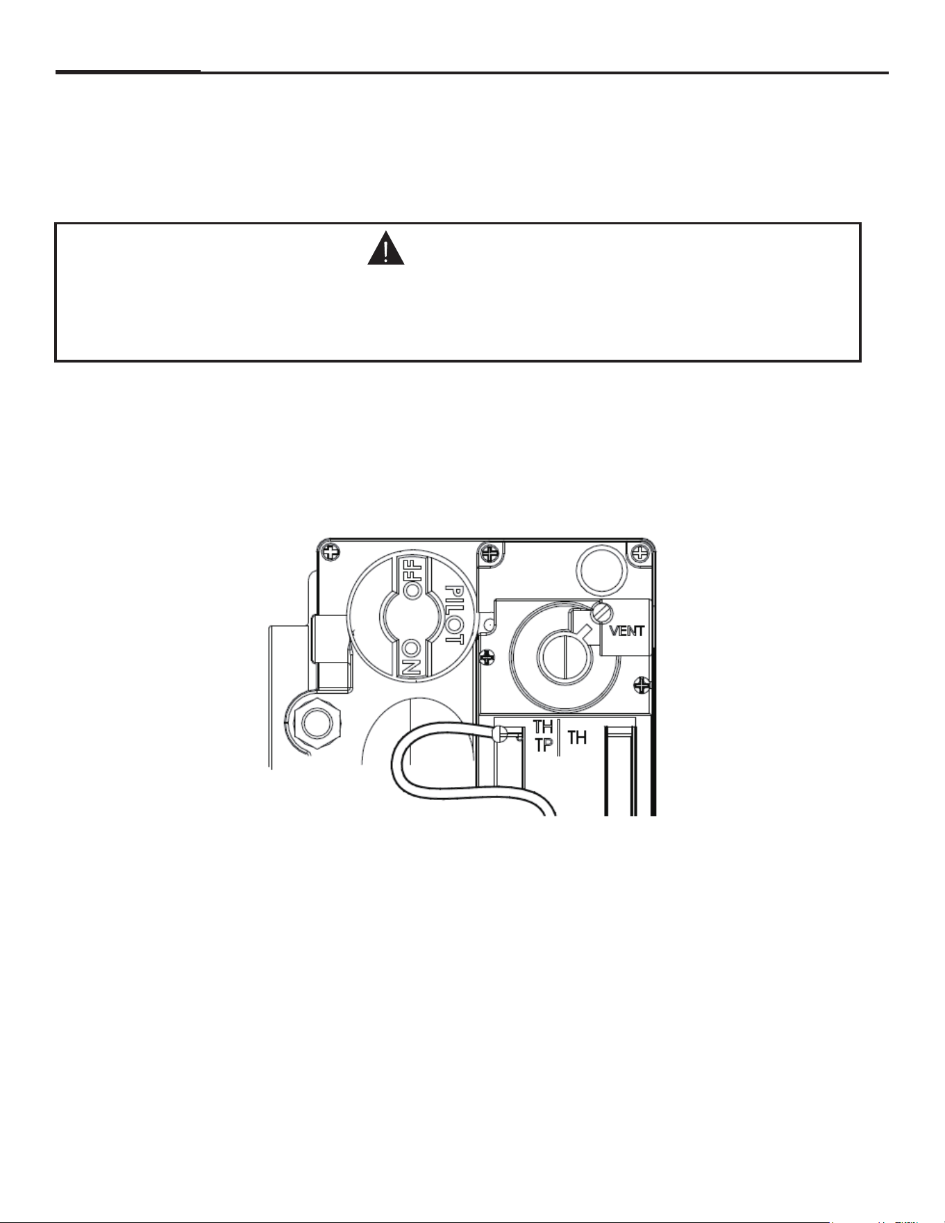
2. Press down the knob of the combination gas valve, turn it counterclockwise to the “PILOT” position
(shown), and continue to press the knob down.
3. While pressing the knob down, use a lit match to ignite the pilot. Continue to press the knob down for
about 30 seconds. If the pilot does not stay lit when the knob is released, repeat the lighting procedure
and keep the knob down longer. Adjustment of pilot flame may be necessary.
4. When the pilot stays lit, turn the knob counterclockwise to the “ON” position. Do not press down on
the knob in this step.
5. Do NOT turn the thermostat “ON” until the frypot is filled with oil or solid shortening.
6. Once the frypot is filled with shortening, set the thermostat to the desired temperature
IF YOU SMELL GAS DURING THE LIGHTING PROCEDURE, IMMEDIATELY SHUT OFF THE
GAS SUPPLY UNTIL THE LEAK HAS BEEN CORRECTED.
CAUTION
16
OPERATION (continued)
FILLING THE FRYPOT
SHUTDOWN PROCEDURE
AUTOMATIC PILOT VALVE
RELIGHTING
1. Close drain valve completely before filling the frypot.
2. When the fryer is new, fill the frypot with water and clean thoroughly (see “Weekly Cleaning” on page
15) in order to remove protective coatings and any foreign matter.
3. Remove the basket support frame when filling the frypot with solid shortening.
4. When solid shortening is used, be careful not to bend, break, or twist the thin capillary wires of the
sensing elements located in the frypot.
5. Pack solid shortening into the zone below the tubes, all spaces between the tubes, and at least an
inch above the top of the tubes before lighting the fryer. If any air spaces are left around the heat tube
surfaces when the heat is turned on, the tube surfaces will become red hot, burn the solid shortening,
weaken the frypot, and could result in a fire.
6. To prevent burning or scorching the solid shortening, keep the thermostat set at the lowest tempera-
ture until all the solid shortening between and above the tubes has been melted. Additional solid short-
ening can then be added until the desired frying depth has been reached.
7. Replace the basket support frame over the frypot heat tubes.
Standby: Turn knob on the combination gas valve to the “PILOT” position. At this setting, only the pilot
burner will remain ignited.
Complete Shutdown: Turn knob on the combination gas valve clockwise, press down on the knob and
continue to turn to the “OFF” position.
The Automatic Pilot Valve provides an automatic safety shutoff for the fryer when the pilot flame is
extinguished. When the pilot flame is burning, the valve is held open electromagnetically by the electri-
cal current from a thermopile in the pilot flame. When the pilot flame goes out, generation of current
ceases and the valve closes automatically.
1. Shut off all gas.
2. Wait five minutes.
3. Follow the “Lighting” procedure described on page 15.
NEVER ATTEMPT TO MELT A SOLID BLOCK OF SHORTENING ON TOP OF THE HEAT
TUBES.NEVER START THE BURNERS WHEN THE FRYPOT IS EMPTY.
CAUTION
In the event of a main burner ignition failure, a five minute purge period must be observed
prior to reestablishing the ignition source.
WARNING
COOKING HINTS
17
COOKING HINTS and CLEANING
HIGH LIMIT CONTROL
USER TIPS
DAILY CLEANING
Gas floor model fryers are equipped with a secondary heat control that prevents the oil temperature
from rising above 450℉. (Because of the accuracy tolerance of the sensor, the oil temperature may
reach as high as 475℉.)
In the event the fryer shuts down due to this condition, the oil must be cooled to below 400℉ before the
pilot burner can be re-ignited. When the oil has cooled, use the “Lighting” procedure on page 12 to
place the fryer back in operation. If the problem persists, contact your local Service Representative or
the Service Department.
• Smoking oil means that the temperature is too high, or that the oil has broken down.
• Gum in frypot denotes a need for thorough cleaning (see “Weekly Cleaning” on page 15)
• Use different oil for oily foods (mackerel, nutmeg, etc.) than for foods with water-soluble flavors (pota
toes,onions, etc.).
• Taste cool oil for quality. Replace it regularly.
• Poor oil cannot produce good food.
COOKING HINTS
The equipment is constructed with the best quality materials and is designed to provide durable service
when properly maintained. To expect the best performance, your equipment must be maintained in good
condition and cleaned daily. Naturally, the frequency and extent of cleaning depends on the amount and
degree of usage.
Following daily and more extensive periodic maintenance procedures will increase the life of your
equipment. Climatic conditions (e.g., salt air) may result in the need for more thorough and more
frequent cleaning in order to keep equipment performing at optimal levels.
1. Turn thermostat knob to “OFF” position.
2. Place hot-oil in a safe container under the drain and drain the frypot completely.
3. Remove the basket support frame (if applicable) and flush out any sediment remaining in the frypot
with a little hot oil.
If necessary to move the fryer for cleaning, etc., drain oil first to avoid death or serious injury.
WARNING: BURN HAZARD
If disconnection of the restraint is necessary to move the appliance for cleaning, etc., reconnect
it when the appliance is moved to it originally installed position.
WARNING
18
COOKING HINTS and CLEANING (continued)
WEEKLY CLEANING
4. Wipe off the basket support frame and the inside of the frypot with a clean cloth.
5. Close drain valve and strain the oil back into the frypot through several thicknesses of cheesecloth, or
filter it back using a filter machine.
6. Replace the basket support frame (if applicable)
7. Add oil or shortening to MIN oil level mark on rear of frypot.
8. To resume cooking, turn the combination gas valve knob to “ON” position.
1. Follow steps 1 through 4 of the Daily Cleaning procedure (see previous section).
2. Close drain valve and fill frypot with a solution of warm water and boil-out compound
3. Relight the fryer and bring the solution to a gentle boil for at least five minutes.
4. Turn off main burners and let the solution stand until the gum deposits are softened and the carbon
spots and burned grease spots can be rubbed off.
5. Scrub the frypot walls and heat tubes, then drain out frypot and rinse it with clean water.
6. Refill the frypot with clean water and boil again.
7. Turn off gas and drain and rinse well until clean.
8. Wipe dry with a clean cloth.
9. Refill as specified in the “Filling the Frypot” section (see page 13).
MONTHLY CLEANING
1. Perform the Weekly Cleaning procedure (see previous section).
2. Clean around burner and orifices if lint has accumulated.
3. Visually check that burner carry-over ports are unobstructed.
CLEANING STAINLESS STEEL SURFACES
To remove normal dirt, grease and product residue from stainless steel use ordinary soap and water
(with or without detergent) applied with a sponge or cloth. Dry thoroughly with a clean cloth. Never use
vinegar or any corrosive cleaner.
To remove grease and food splatter or condensed vapors that have baked on the equipment apply
cleanser to a damp cloth or sponge and rub cleanser on the metal in the direction of the polishing lines
on the metal. Rubbing cleanser, as gently as possible, in the direction of the polished lines will not mar
the finish of the stainless steel. NEVER RUB WITH A CIRCULAR MOTION. Soil and burnt deposits that
do not respond to the above procedure can usually be removed by rubbing the surface with
SCOTCH-BRITE™ scouring pads or STAINLESS scouring pads. DO NOT USE ORDINARY STEEL
WOOL, as any particles left on the surface will rust and further spoil the appearance of the finish.
NEVER USE A WIRE BRUSH, STEEL SCOURING PADS (EXCEPT STAINLESS), SCRAPER, FILE OR
OTHER STEEL TOOLS. Surfaces that are marred collect dirt more rapidly and become more difficult to
clean. Marring also increases the possibility of corrosive attack. Refinishing may then be required.
Darkened areas, called “heat tint,” sometimes appear on stainless steel surfaces where the area has
been subjected to excessive heat. These darkened areas are caused by thickening of the protective
surface of the stainless steel and are not harmful. Heat tint can normally be removed by the above
cleaning techniques, but tint which does not respond to that procedure calls for a vigorous scouring in
the direction of the polish lines, using SCOTCH-BRITE™ scouring pads or a STAINLESS scouring pad
in combination with a powered
SOME AREAS OF THE FRYPOT MAY BE HOT!
CAUTION
All units are adiusted at the factory. In case of problems in operation at initial installation, check type of
gasand manifold pressure and compare with information listed on the serial plate.
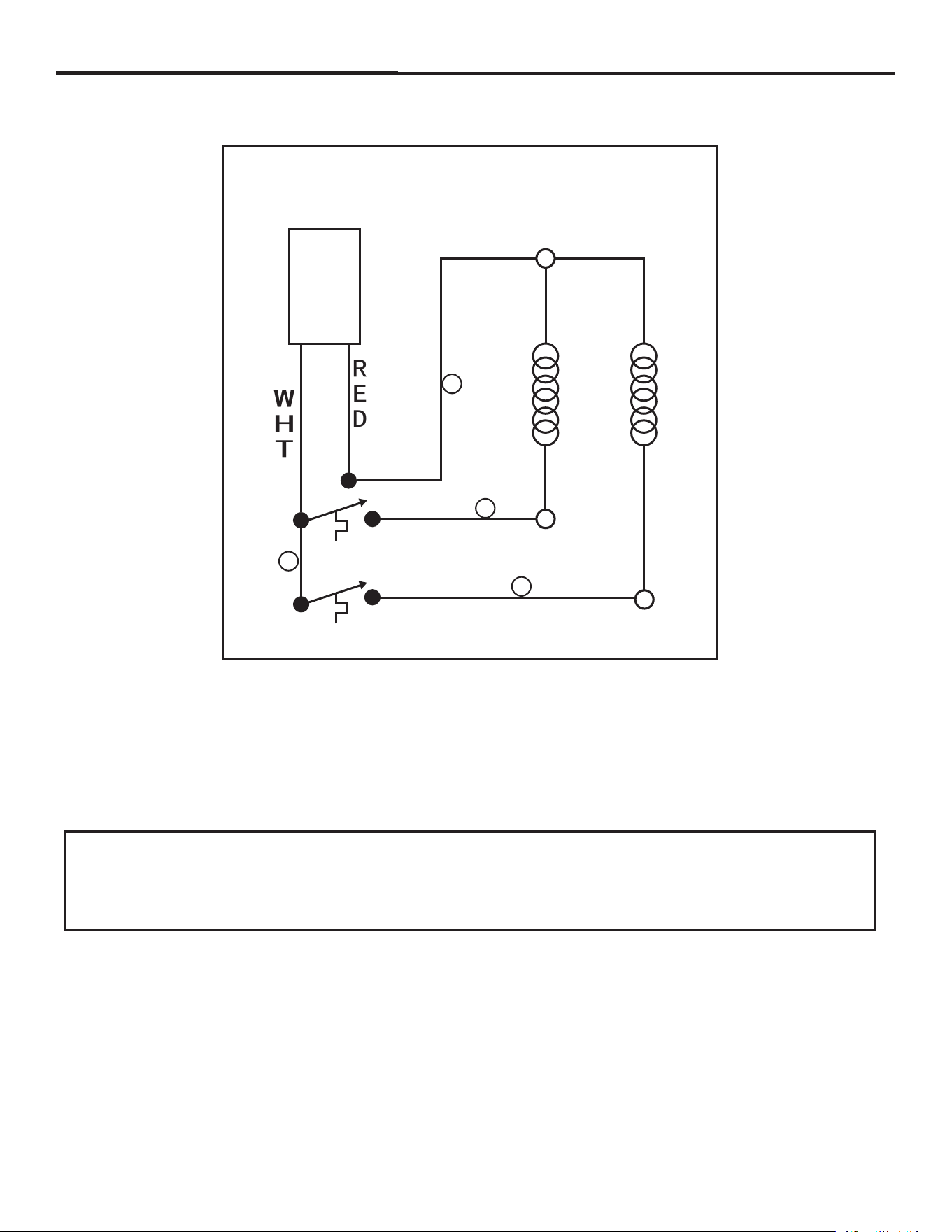
A mill voltage circuit diagram is located inside the front door of the fryer, and also on page 22
SERVICE
19
SERVICE
(FOR AUTHORIZED SERVICE TECHNICIAN ONLY)
cleanser. Heat tint action may be lessened by not applying or by reducing, heat to equipment during
slack periods.
Adjustments and service work may be performed only by a qualified technician who is experi-
enced in.and knowledgeable with, the operation of commercial gas cooking equipment.
However, to assureyour confidence, contact your Service Representative for reliable service,
dependable advice or otherassistance, and for genuine factory parts.
WARNING
Warranty will be void and the manufacturer is relieved of all liability if:
(A) Service work is performed by other than a qualified technician
OR
(B) Other than approved replacement parts are installed.
NOTICE
20
SERVICE (continued)
CHECKING AND ADJUSTING PRESSURE REGULATOR
The combination gas valve (includes pressure regulator) is factory set at 4" W.C. for natural gas and 10"
W.C. for propane gas. To check the manifold pressure, do the following:
1. Turn thermostat “OFF” and combination gas valve knob to the “PILOT” setting.
2. Remove pressure tap plug from burner manifold located directly below the burners in the cabinet.
3. Install a fitting appropriate to connect a manometer.
4. Turn combination gas valve to “ON” position and thermostat to “ON.” The burners will ignite. Be certain
that sufficient oil is covering the tubes.
5. With burners on, read manometer.
6. If the manometer does not read 4" W.C. for natural gas, or 10" W.C. for propane gas, adjust regulator.
7. Remove regulator adjustment screw cap (see diagram on page 15).
8. With small screwdriver rotate adjustment screw “CLOCKWISE” to increase or “COUNTERCLOCKWISE”
to decrease pressure. Be sure to adjust with burners “ON.”
9. Turn thermostat “OFF” and set combination gas valve knob to “PILOT” position.
10. Remove manometer and replace pressure tap plug.
11. Replace adjustment screw cap.
CHECKING AND ADJUSTING CALIBRATION OF THERMOSTAT
All thermostat controls are carefully calibrated at the factory (i.e., the dial is properly set to control appli-
ance
temperatures accurately). Only a qualified appliance service technician should perform this adjustment.
1. To check appliance temperatures, use a thermocouple-type temperature test instrument or reliable
thermometer. Place the thermocouple of test instrument or thermometer in the center of the frypot.
2. Turn the control dial to the temperature setting requiring the greatest accuracy. Allow enough time for
temperature to stabilize, or until several temperature readings are identical.
3. Recalibrate if setting and actual temperature differ by more than 10℉.
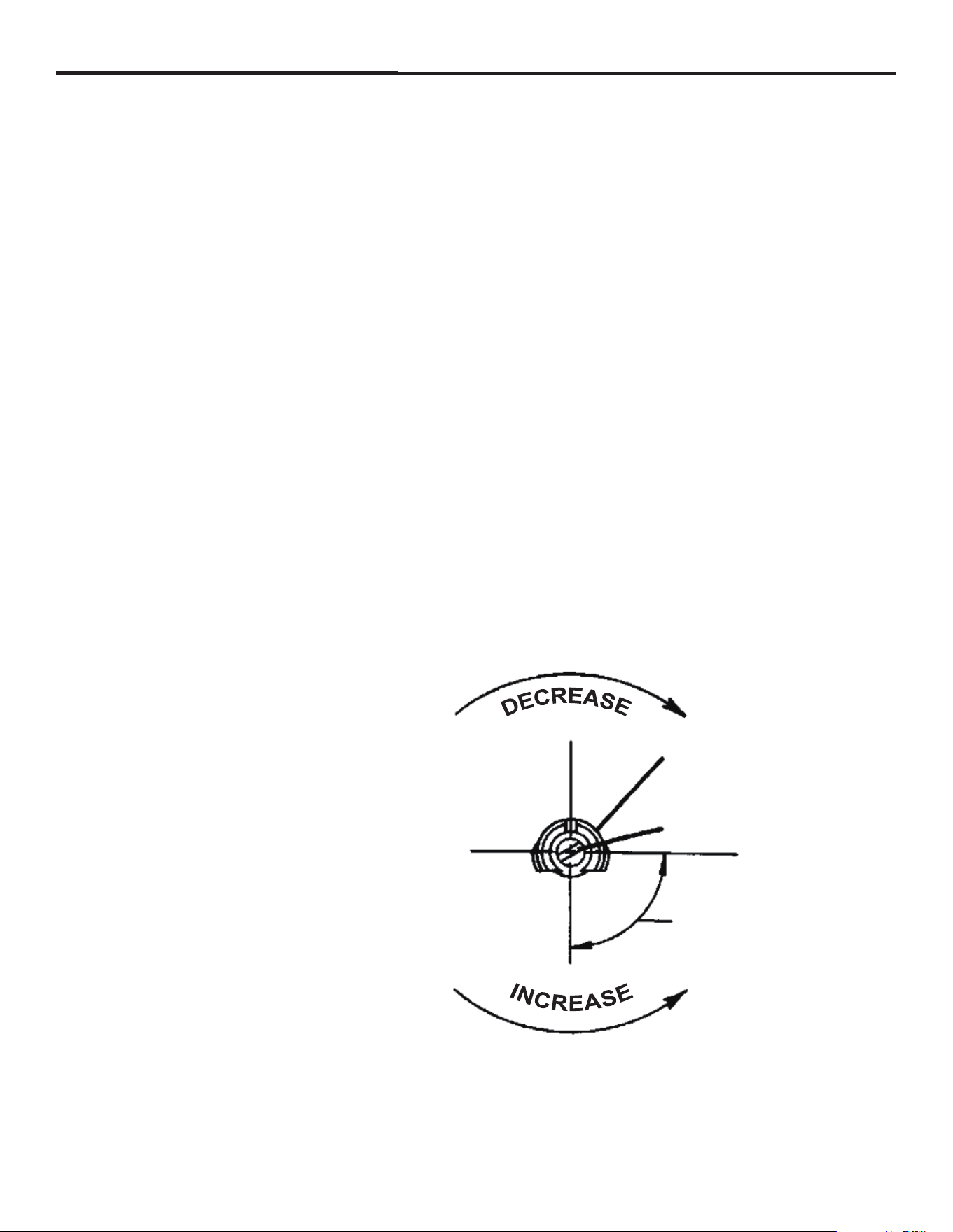
4. Remove dial from dial shaft “B.” Be careful that
dial shaft does not rotate in either direction (which
would change the dial setting).
5. Hold dial shaft “B” steady and with a screwdriver
turn calibration screw “A” clockwise to decrease the
temperature, or counterclockwise to increase the
temperature.
6. Replace dial. Let the appliance operate until the
temperature has stabilized before a final check is
made to determine whether or not the calibration
has been corrected.
7. Once correct, seal the calibration screw with
glyptol.
DIAL
SHAFT
“B”
CALIBRATION
SCREW“A”
1/4 TURN CHANGES
TEMPERATURE 18°
21
SERVICE (continued)
CHECKING AND ADJUSTING AUTO SAFETY PILOT
TROUBLESHOOTING
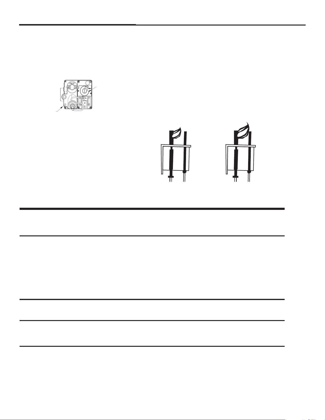
The pilot flame should surround the thermopile for 1/2". It must be large and sharp enough to cause the
thermopile to glow a dull red, or sufficient to hold the safety valve open.
NOTE: Vibrations or shock caused by shaking or pounding baskets on top surface or by slamming door
may cause Hi-Limit Control Switch to open. If this condition persists, additional cushioning may be
added to the rubber grommets supporting this control to absorb these shocks.
2. Adjust pilot key to provide properly
sized flame shown in diagram B.
Diagram A shows an improperly
adjusted pilot
3. Replace pilot adjustment cap.
Problem
Burners do not come on
Gas supply to unit off.
Combination gas valve is in “OFF” or “PILOT” position.
Pilot not ignited.
Thermostat not “ON.”
Combination gas valve is in “OFF” position.
Pilot gas not adjusted properly.
Gas supply to unit off.
Bad thermopile.
Dirty thermopile connections at combination gas valve
or high limit.
Clogged orifice.
Draft condition.
Air in gas line.
Improper ventilation system.
Unit connected to wrong gas supply.
Pressure not adjusted correctly.
Pilot gas not adjusted correctly.
Wrong size orifices.
Connected to wrong gas supply.
Pressure not adjusted correctly.
Flue obstructed.
Pilot will not stay ignited
Pilot produces carbon deposits
Burners produce carbon deposits
Likely Cause
1. Remove pilot adjustment cap
A B
Pressure Adjustment
Under this Cap
Pilot Adjustment
Under this Screw
INSTALLATION OF OTHER THAN GENUINE PARTS WILL VOID THE WARRANTY ON THIS
EQUIPMENT.
NOTICE
22
SERVICE (continued)
Wiring Diagram
PARTS
The serial plate is located inside the front door on the left side.
Replacement parts may be ordered either through a Authorized Parts Distributor or a Authorized Service
Agency.
When ordering parts, please supply the Model Number, Serial Number, Part Number, and Description.
WIRE DIAGRAM
TP
Limit
TP
(PP-L)
(TH-H)
TH/TP
TH
(TH-L)
T-stat
RED
WHT
1
2
3
4
23
Warranty
What this limited warranty covers:
• applies
exclusively to the original Forno appliance
an
authorized Forno dealer, distributor, or retailer, and installed
in the United S
must remain
within the country of original purchase.
•
year from the
date of original retail purchase and covers parts and labor.
•
• ited to commercial use. Any
residential use of the Product will void this warranty.
• Forno Appliances will repair or replace, at its discretion, any
component or part that proves to be defective due to
manufacturing defects in materials or workmanship under
normal commercial use during the warranty period. Repair or
replacement will be performed by a Forno Authorized Service
provider during normal working hours.
•
installation, misuse, abuse,
im
Purchaser is responsible for ensuring the Product is
reasonably accessible for service.
•
age is non-transferable. In the event of
replacement of parts or the entire Product, the replacement
will assume the remaining warranty period from the original
period will not be extended.
Important
Retain proof of original purchase to establish the warranty period.
liability on any claim of any kind, with respect to the
goods and/or services provided, shall in no event exceed the
value of the product, service, or part thereof which has given rise
to the claim.
30-Day Cosmetic Warranty
Purchaser must inspect the Product at the time of delivery.
Forno warrants that the Product is free from manufacturing-
related cosmetic defects in materials and workmanship for a
period of thirty
days from the date of original retail
purchase.
• Paint blemishes
•
Cosmetic warranty does NOT cover:
•
Damage resulting from improper transportation, handling, or
dents, warping, deformation, or
damaged components, cracked or damaged glass
components
• variations in painted or enameled parts
• Differences caused by lighting conditions, installation
location, or similar factors
• Stains, corrosion, or discoloration caused by external
substances or environmental conditions
• costs
• Display models, floor m open-box,
products, or demo units
What Exclusion: What is not covered
• Installation services at the time of purchase or during product
replacement.
• Use of the Product in any residential or non-commercial
application
• Use of the Product for purposes other than its intended use
• Service or repairs performed by anyone other than a Forno
Authorized Service provider
• Damage or repair services required to correct work performed
by unauthorized parties or the use of unauthorized parts.
• Installation not in accordance with local/state/county fire
codes, electrical codes, gas codes, plumbing codes, building
codes, laws or regulations.
• Defects or damage due to improper storage of the Product.
• Defects, damage or missing parts on products sold out of the
original factory packaging or from displays.
• Service calls or repairs to correct an incorrect installation of
the Product and/or related accessories.
• Replacement of parts/service calls to connect, convert or
otherwise repair the electrical wiring and/or gas line in order
to properly use the product.
• Replacement of parts/service calls to provide instructions and
information on the use of the Product.
• Replacement of parts or service calls to correct issues arising
from use of the Product in a manner inconsistent with normal
and customary commercial use.
• Replacement of parts/service calls due to wear and tear of
components such as seals, knobs, pan supports, shelving,
cutlery baskets, buttons, touch displays, scratched or broken
ceramic-glass tops.
• Replacement of parts/service calls for lack of/improper
maintenance, including but not limited to: build up of residues,
stains, scratches, discoloration, corrosion.
• Defects and damages arising from accidents, alteration,
misuse, abuse or improper installation.
• Defects and damages arising from Product transport, logistics
and handling. Inspection of the product must be made at time
of delivery. Following receipt and inspection, the selling
dealer/delivery company must be notified of any issues
arising from handling, transport and logistics.
• Defects or damage resulting from external forces beyond the
control of Forno Appliances, including but not limited to wind,
rain, sand, fire, flooding, mudslides, freezing temperatures,
excessive moisture or prolonged exposure to humidity, power
surges, lightning, structural failures surrounding the
appliance, or other natural phenomena.
• Products whose serial number has been altered/damaged/
tampered with. In no case shall Forno be held liable or
responsible for damage to surrounding property, including
furniture, cabinetry, flooring, panels, and other structures
surrounding the Product. Forno is neither liable nor
responsible for the Product if it is located in a remote area or
an area where certified trained technicians are not reasonably
available. Purchaser must bear any transportation and
delivery costs of the Product to the nearest Authorized
Service Center or the additional travel expenses of a certified
trained technician.
• Chips

24
Warranty (continued)
There are no warranties, either express or implied, other than those listed and described above, including but not limited
to any implied warranties of merchantability or fitness for a particular purpose, that shall apply after the express warranty
period stated above.
No other express warranty or guarantee given by any person, firm, or corporation with respect to this Product shall be
binding on Forno.
Forno shall not be liable for any loss of revenue or profits, failure to realize expected savings or other benefits, time away
from work, loss of food or beverages, travel or lodging expenses, costs to rent or purchase replacement appliances, or
any remodeling or construction expenses.
Forno shall also not be liable for any indirect, incidental, special, or consequential damages arising from the use, misuse,
or inability to use this Product, regardless of the legal theory on which the claim is based, and even if Forno has been
advised of the possibility of such damages.
In no event shall Forno’s total liability exceed the purchase price of the Product giving rise to the claim.
The Purchaser assumes all risk and liability for any loss, damage, or injury to persons or property resulting from the use,
misuse, or inability to use the Product, except where such damage is directly caused by the negligence of Forno.
This limited warranty is non-transferable, applies only to the original Purchaser, and constitutes the Purchaser’s
exclusive remedy.
DISCLAIMER OF WARRANTIES AND LIMITATION OF LIABILITY

Customer Support: Call 1-866-231-8893 or email: [email protected]