EN, English
Operator's manual
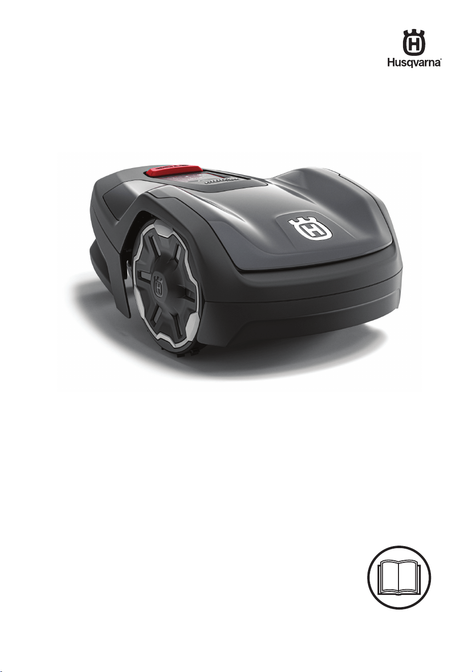
Automower
®
Aspire
™
R4
Read the operator's manual carefully and make sure that you
understand the instructions before you use the product.

Contents
1 Safety
1.1 Safety definitions...................................................3
1.2 General safety instructions....................................3
1.3 Safety instructions for installation..........................4
1.4 Safety instructions for operation............................4
1.5 Safety instructions for maintenance...................... 4
1.6 Battery safety........................................................ 5
1.7 To lift and move the product..................................5
1.8 Cyber security....................................................... 5
2 Introduction
2.1 Introduction........................................................... 7
2.2 Product overview...................................................8
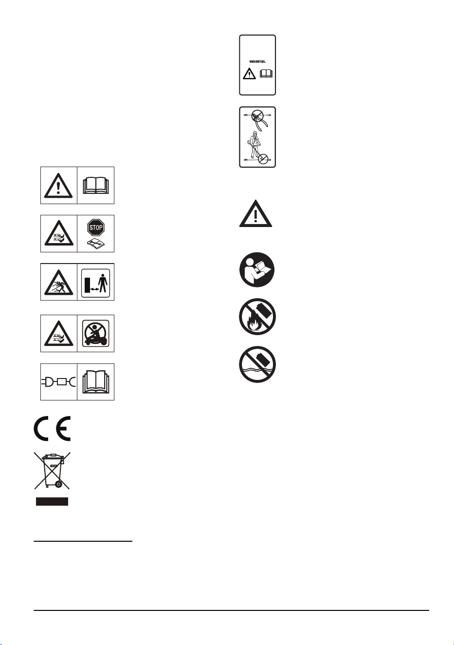
2.3 Symbols on the product........................................ 9
2.4 Symbols on the battery......................................... 9
2.5 General manual instructions................................. 9
2.6 Keypad.................................................................. 9
2.7 LED indicator on the keypad............................... 10
2.8 Product damage..................................................12
3 Installation
3.1 Introduction - Installation..................................... 13
3.2 Primary components for installation.................... 13
3.3 To prepare for installation................................... 13
3.4 Before the installation of the wires...................... 13
3.5 Installation of the product.................................... 18
3.6 To put the wire or the cable into position
with stakes................................................................ 20
3.7 To bury the wire or the cable...............................20
3.8 To extend the boundary wire or the guide wire... 20
3.9 After the installation of the product......................21
3.10 To install the Automower
®
Connect app........... 21
3.11 To start the product for the first time................. 21
4 Settings
4.1 Schedule............................................................. 22
4.2 Operation............................................................ 22
4.3 Installation........................................................... 23
4.4 Accessories.........................................................24
4.5 General............................................................... 24
4.6 Safety.................................................................. 24
4.7 Automower
®
Connect ........................................ 24
4.8 Download firmware over the air (Firmware
over the air FOTA).................................................... 24
5 Operation
5.1 To use the ON/OFF button..................................25
5.2 To start the product............................................. 25
5.3 Operating modes.................................................25
5.4 To stop the product............................................. 27
5.5 To set the product to OFF................................... 27
5.6 To charge the battery.......................................... 27
5.7 Cutting height adjustment................................... 27
6 Maintenance
6.1 Introduction - maintenance..................................29
6.2 Maintenance schedule........................................ 29
6.3 Clean the product................................................30
6.4 Replacement of the blades................................. 31
6.5 Battery.................................................................31
6.6 Winter service..................................................... 32
7 Troubleshooting
7.1 Introduction - troubleshooting..............................33
7.2 Fault messages...................................................33
7.3 Information and warning messages.................... 37
7.4 Indicator lamp in the charging station................. 38
7.5 Symptoms........................................................... 39
7.6 Find breaks in the loop wire................................ 40
8 Transportation, storage and disposal
8.1 Transportation..................................................... 43
8.2 To put the product into storage........................... 43
8.3 Disposal.............................................................. 43
9 Technical data
9.1 Technical data.....................................................45
9.2 Registered trademarks........................................47
2
1886 - 003 - 12.03.2026
1 Safety
1.1 Safety definitions
Warnings, cautions, and notes are used to point out
particularly important parts of the manual.
WARNING: Used if there is a risk of
injury or death for the operator or bystanders
if the instructions in the manual are not
obeyed.
CAUTION: Used if there is a risk of
damage to the product, other materials or
the adjacent area if the instructions in the
manual are not obeyed.
Note: Used to give more information that is necessary
in a given situation.
1.2 General safety instructions
WARNING: Read the warning
instructions that follow before you use the
product.
• Read the Operator’s manual carefully and make
sure you understand the instructions before you
use the product. Keep for future reference.
• This appliance is not intended for use by children
or persons with reduced physical, sensory or
mental capabilities (that could affect a safe
handling of the product), or lack of experience
and knowledge, unless they have been given
supervision or instruction concerning use of the
appliance by a person responsible for their safety.
However, EU requirements allows this appliance
to be used by children aged from 8 years and
above and persons with reduced physical, sensory
or mental capabilities or lack of experience and
knowledge, if they have been given supervision
or instruction concerning use of the appliance in
a safe way and understand the hazards involved.
Children shall not play with the appliance. Cleaning
and user maintenance shall not be made by
children without supervision.
• The product must only be used with the equipment
recommended by Husqvarna. All other types of
use are incorrect.
• The product is not a toy. The blades of the product
can cause injury to persons and animals.
• Do not let children less than 8 years of age be
in the work area during operation. Children and
animals must be supervised at all times during
operation.
• All persons must be a minimum of 3 m/10 ft away
from the product when it is in operation. Do not for
example sleep or sunbathe in the work area when
the product is in operation.
• Warning signs must be put around the work area
of the product if it operates in public areas. The
signs must have the text that follows: Warning!
Automatic lawn mower! Keep away from the
machine! Supervise children!
• Do not touch moving hazardous parts, such as the
blade disc, before it has come to a complete stop.
• To set the product to OFF, go behind the product
and push the STOP button and then push the
ON/OFF button for 3 seconds to set the product
to OFF. When the product is set to OFF, wait
minimum 3 seconds before you move the product.
• Set the product to OFF before you clear a
blockage, do maintenance or examine the product,
and if the product starts to vibrate abnormally.
Examine the product for damage before you start
the product again. Do not use the product if it is
damaged.
• If an injury or accident occur, get medical aid.
• Do not put power supply cable and extension cable
in the work area. This can cause damage to the
cables.
• Do not connect a damaged cable or plug, or touch
a damaged cable, before it is disconnected from
the power outlet. Disconnect the plug from the
power outlet if the cable becomes damaged while
in operation. A worn or damaged cable increases
the risk of electrical shock. A damaged cable must
be replaced by service personnel.
• When you connect the power supply to the power
outlet, use a residual-current device (RCD) with a
tripping current of maximum 30 mA.
• Only charge the product in the included charging
station. For safe disposal of the battery, refer to
Disposal on page 43
. Incorrect use may result in
electric shock, overheating or leaking of corrosive
liquid from the battery. In the event of leakage of
electrolyte, flush with water/neutralizing agent. Get
medical aid if corrosive liquid comes in your eyes.
• Use only original batteries recommended by
Husqvarna. Product safety cannot be guaranteed
with other than original batteries. Do not use non-
rechargeable batteries.
• Follow the installation instructions that includes to
specify the work area, refer to
Installation on page
13
.
• Follow the instructions about to start and operate
the product, refer to
Operation on page 25
.
1886 - 003 - 12.03.2026
Safety - 3
• If there is a risk of thunderstorm, Husqvarna
recommends that the power supply and all the
wires to the charging station are disconnected
to decrease the risk of damage to electrical
components. Connect the power supply and all
the wires again if there is no longer a risk of
thunderstorm. It is important that all wires are
connected correctly.
• Follow the maintenance instructions and if
necessary use Husqvarna original spare parts,
refer to
Maintenance on page 29
.
• For technical data such as weight, dimensions and
noise emission values, refer to
Technical data on
page 45
.
• The operator is responsible for accidents or
dangers that occurs to other persons or property.
• The product must only be operated, maintained
and repaired by persons that are fully conversant
with its special characteristics and safety
regulations.
• It is not permitted to change the initial design of the
product.
• Obey national regulations about electrical safety.
• Husqvarna does not guarantee full compatibility
between the product and other types of
wireless systems such as remote controls, radio
transmitters or equivalent.
• Operation and storage temperature range is 0–50
°C / 32–122 °F. Temperature range for charging is
0–45 °C / 32–113 °F. Too high temperatures can
cause damage to the product.
1.3 Safety instructions for installation
WARNING:
Read the warning
instructions that follow before you use the
product.
• Do not install the charging station in an area where
there is a risk that persons trip on it.
• Do not install the charging station, including any
accessory, at a location that is below, or within 60
cm / 24 in. from, any combustible material. In case
of malfunction, heating of the charging station and
the power supply may occur and create a potential
risk of fire.
• Do not put the power supply at a height where
there is a risk it can be put in water. Do not put the
power supply on the ground.
• Do not encapsulate the power supply. Condensed
water can harm the power supply and increase the
risk of electrical shock.
• Do not install the charging station where there are
pests, for example ants.
• Applicable to USA/Canada. If power supply is
installed outdoors: Risk of Electric Shock. Install
only to a covered Class A GFCI receptacle (RCD)
that has an enclosure that is weatherproof with the
attachment plug cap inserted or removed.
• Do not install the charging station where there is a
risk of standing water.
1.4 Safety instructions for operation
WARNING: Read the warning
instructions that follow before you use the
product.
• Keep your hands and feet away from the rotating
blades. Do not put your hands or feet near or
below the product when it is set to ON.
• Use the park mode or set the product to OFF
when persons, especially children or animals are
in the work area. Refer to
Park until further notice
on page 26
. Husqvarna recommends to set the
product to operate when the work area has no
activity. The product can cause injury to animals at
night in work area, for example hedgehogs. Refer
to
Park on page 26
.
• Make sure that there are no objects such as
stones, branches, tools or toys on the lawn. The
blades on the product and the objects can be
damaged.
• Do not lift the product or move it when it is set to
ON.
• Do not to let the product collide with persons or
animals. If a person or animal comes in the way of
the product, stop the product immediately. Refer to
To stop the product on page 27
.
• Do not put objects on top of the product or its
charging station.
• Do not use the product if the STOP button does
not work.
• Always set the product to OFF when it is not in
operation. The product can only start when you
enter the correct PIN code.
• Do not use the product at the same time as a
pop-up sprinkler. Use the
Schedule
function so the
product and pop-up sprinkler do not operate at the
same time. Refer to
Park on page 26
.
• Do not let the product operate when there is
standing water in the work area. For example when
heavy rain forms pools of water.
1.5 Safety instructions for maintenance
WARNING:
Read the warning
instructions that follow before you do
maintenance on the product.
• Set the product to OFF when you do maintenance
on the product.
• Do not use a high-pressure washer to clean the
product. Do not use solvents to clean the product.
4
- Safety 1886 - 003 - 12.03.2026
• Disconnect the plug to the charging station before
you clean or do maintenance of the charging
station.
1.6 Battery safety
WARNING: Read the warning
instructions that follow before you use the
product.
• Lithium-ion batteries can explode or cause fire if
disassembled, short-circuited, exposed to water,
fire, or high temperatures. Handle carefully, do
not dismantle, open the battery or use any type
of electrical/mechanical abuse. Avoid storage in
direct sunlight.
• Do not use a damaged battery. Dispose the battery
if it is damaged. Refer to
Disposal on page 43
.
1.7 To lift and move the product
WARNING: The product must be set
to OFF before you lift the product. The
product is disabled when the indicator on the
ON/OFF button goes off.
CAUTION: Do not lift the product when
it is parked in the charging station. It can
cause damage to the charging station and/or
the product. Push the STOP button and
pull the product out of the charging station
before you lift it.
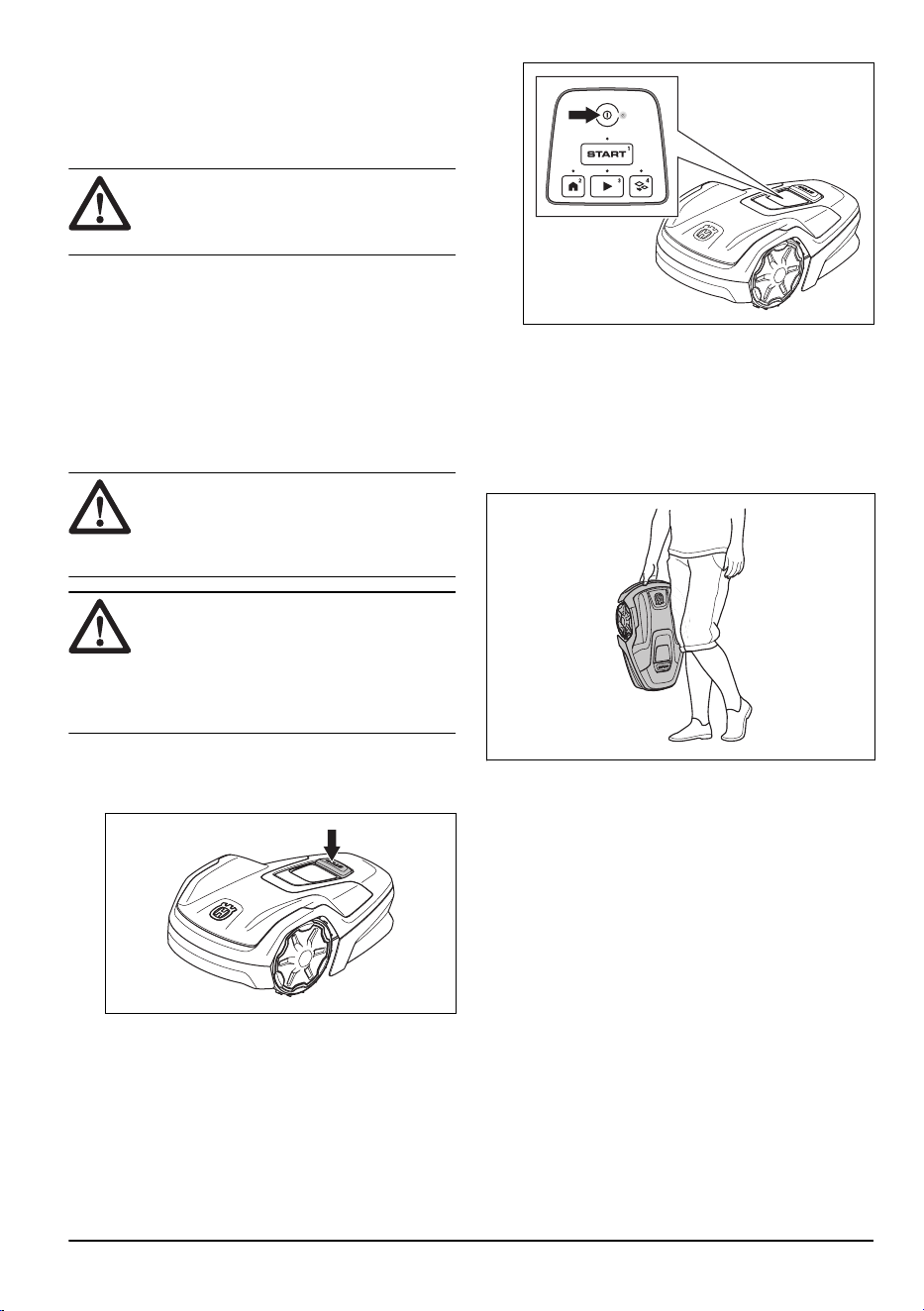
To safely move the product:
1. Push the STOP button to stop the product.
2. Push the ON/OFF button for 3 seconds to set the
product to OFF.
3. Enter the PIN code if it is necessary.
4. Make sure that the product is disabled. The
indicator on the ON/OFF button goes off when the
product is disabled. Refer to
LED indicator on the
keypad on page 10
.
5. Lift the product by the handle with the blade disc
away from your body.
1.8 Cyber security
Security recommendations:
• Do not set up or operate the product on untrusted
or public networks.
• At regular time intervals, do a check if there are
firmware updates available to install to keep the
system secure.
1.8.1 Bluetooth
®
interface
The Bluetooth
®
interface is enabled by default to help
with set up, mobile device connection, local device
control and configuration of the product with a mobile
device. The Bluetooth
®
connection uses a PIN code
or password that is different for each product through
the app. All device connection are made safe with a
standard BLE encryption. Use a strong, unique PIN to
increase security.
1.8.2 Wi-Fi interface
The Wi-Fi interface on the product enables connection
to your private Wi-Fi network for remote control through
1886 - 003 - 12.03.2026
Safety - 5

the companion app and for firmware updates, and
location-based services. The Wi-Fi connections are
protected with WPA2/WPA3 encryption protocols. Use
a strong, unique password for your private Wi-Fi network
and make sure that the product connects only to trusted
networks.
1.8.3 External services
These services are available through the network
interfaces:
• Backend Services: Enables secure management
and configuration of the product through
authenticated access with the companion app
or web-based portal, as well as telemetry data
exchange.
• Firmware update service: This service sends new
firmware over the air (FOTA) to the product. These
updates keep the product security and product
functions up to date.
6 - Safety 1886 - 003 - 12.03.2026
2 Introduction
2.1 Introduction
Serial number:
Product number:
PIN code:
The serial number and the product number are on the product rating plate and on the product carton.
• Register your product on www.husqvarna.com. Enter the serial number of the product, the product number and
the date of purchase to register your product.
2.1.1 Support
For support about the product, go to the Support section
on to access instructions, troubleshooting guides, or
to use the Husqvarna Self-Service and the Product
Assistant (if available in your market). For more support
about the product, speak to your Husqvarna servicing
dealer.
2.1.2 Product description
Note: Husqvarna regularly updates the appearance
and function of the products. Refer to
Support on page
7
.
The product is a robotic lawn mower. The product has a
battery power source and cuts the grass automatically. It
continuously alternates between mowing and charging.
The movement pattern is random, which means that the
lawn is mowed evenly and with less wear. The boundary
wire and the guide wire controls the movement of the
product within the work area. Sensors in the product
senses when it is approaching the boundary wire. The
front of the product always passes the boundary wire
by a specific distance before the product turns around.
When the product hits an obstacle or approaches the
boundary wire the product selects a new direction.
You can select the operation settings in the Automower
®
Connect or with the buttons on the keypad of the
product. The app and the LED status indicator show the
operation mode of the product.
The product has a maximum cutting time each day
because of the maximum capacity of the product. The
operation time of the product that includes to cut, search
and to charge is approximately 11-12 hours each day.
2.1.2.1 Mowing technique
The frequent cutting technique improves the grass
quality and decreases the use of fertilizers. Collection
of grass is not necessary.
2.1.2.2 Find the charging station
The product operates until the battery state of charge
is low, then the product starts to go to the charging
station. The guide wire is put from the charging station
to a remote part of the work area or through a narrow
passage. The guide wire is connected with the boundary
wire to make it easier and faster for the product to find
the charging station.
2.1.2.3 Automower
®
Connect
Automower
®
Connect is a free app for your mobile
device that makes it possible to select the operation
settings remotely. The product can connect to the app
with Bluetooth
®
and Wi-Fi. When you are near the
product you can connect with Bluetooth
®
. When the
product is connected to your Wi-Fi network you can
control the product from everywhere. Refer to
To install
the Automower
®
Connect app on page 21
.
1886 - 003 - 12.03.2026
Introduction - 7
2.2 Product overview
2
23
15
16
6
7
14
8
3
4
5
10
11
1
2
13
9
1
18
17
20
19
21
22
25
24
26
28
29
27
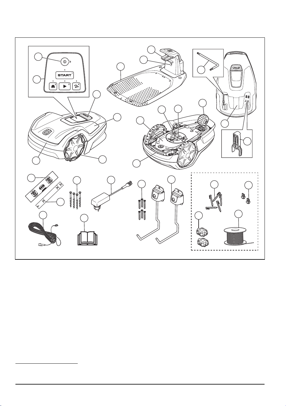
1. ON/OFF button
2. Keypad
3. Stop button
4. Top cover
5. Body
6. Front wheels
7. Charging station
8. Contact plates
9. LED for operation check of the charging station,
boundary wire and guide wire
10. Handle
11. Chassis box with electronics, battery and motors
12. Cutting system
13. Blade disc
14. Rear wheel
15. Torx key for cutting height adjustment
1
16. Rating plate
2
17. Drilling template (the drilling template is removed
from the carton of the product)
18. Measurement gauge for installation of the
boundary wire (the measurement gauge is
removed from the carton of the product)
19. Low-voltage cable
20. Screws to attach the charging station
21. Operator’s Manual and Quick Guide
1
Found below the top cover. The top cover must be removed to access it.
2
Found below the top cover. The top cover must be removed to access it.
8 - Introduction 1886 - 003 - 12.03.2026
22. Power supply
3
23. Maintenance tool
4
24. Screws to attach the storage hook
25. Storage hook
26. Stakes
5
27. Couplers for the loop wire
6
28. Connectors for the loop wire
7
29. Loop wire for boundary wire and guide wire
8
2.3 Symbols on the product
These symbols can be found on the product. Make sure
that you understand them.
WARNING: Read the opera-
tor instructions before you op-
erate the product.
WARNING: Disable the prod-
uct before maintenance or
before you lift the product.
WARNING: Keep a safe dis-
tance from the product when
it is in operation. Keep your
hands and feet away from the
rotating blades of the product.
WARNING: Do not sit on
the product. Do not put your
hands or feet near or below
the product.
Use a detachable power sup-
ply as specified on the rating
plate adjacent to the symbol.
This product complies with the applicable
EU Directives.
The product is not domestic waste.
Recycle the product at an approved
disposal location for electrical and
electronic equipment.
Warranty seal. The warranty will not be
applicable if the seal is broken.
Do not make modifications on the low-
voltage cable.
Do not use a hedge trimmer or a grass
trimmer near the low-voltage cable.
2.4 Symbols on the battery
WARNING: Lithium-ion batteries can
explode or cause fire if disassembled,
short-circuited or handled roughly. Do not
expose to water, fire or high temperature.
Read the user instructions.
Do not discard the battery into fire and do
not expose the battery to a heat source.
Do not immerse the battery into water.
2.5 General manual instructions
The following system is used in the Operator’s manual
to make it easier to use:
• Text written in
italics
is a text that is shown in
the app or is a reference to another section in the
Operator’s manual.
• Text written in bold is one of the buttons on the
product.
2.6 Keypad
The keypad on the product is used to enter the PIN code
and to select an operation mode for the product. Refer
3
The appearance can be different for different markets.
4
Found below the top cover. The top cover must be removed to access it.
5
Only included in the installation kit.
6
Only included in the installation kit.
7
Only included in the installation kit.
8
Only included in the installation kit.
1886 - 003 - 12.03.2026 Introduction - 9
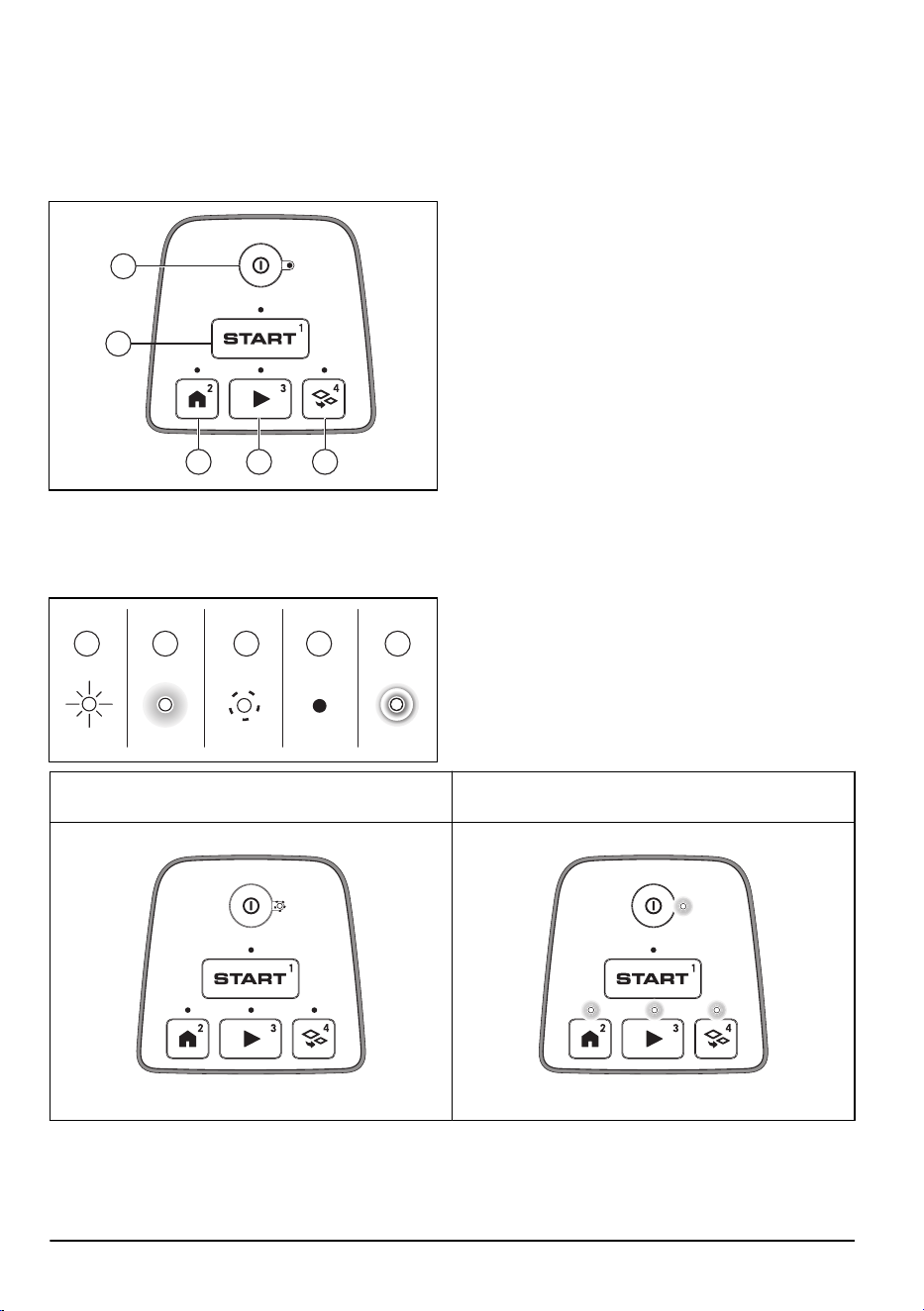
to
Operating modes on page 25
. The buttons on the
keypad with flashing lights are the available operating
modes for the product that you can select. You must
enter the PIN code for the product before you can select
an operating mode. The buttons that have a number are
used to enter the PIN code. Refer to
PIN code on page
24
.
EDC
A
B
• The ON/OFF button (A) is used to set the product
to ON or to OFF.
• The Start button (B) is used to start the operation
of the product.
• The Park button (C) is used to send the product to
the charging station.
• The Play button (D) is used to cut the main area.
• The Secondary area button (E) is used to cut the
secondary area.
2.7 LED indicator on the keypad
The LED indicator on the keypad shows the product status. There are 5 light modes on the LED indicator: the light
flashes quickly (A), the light is solid (B), the light flashes slowly (C), the light is out (D), and the light pulsates (E).
A B C D E
Standby: When the product is not in use for 3 minutes,
the product sets to standby mode.
Idle: The product is ON and in idle mode until you select
an operating mode.
10 - Introduction 1886 - 003 - 12.03.2026
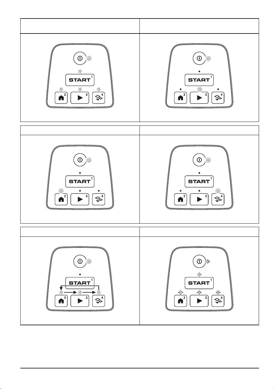
Waiting for PIN code.
Cutting main area as specified in the set
Schedule
or
Override Schedule
.
Parked, until
Next schedule
or until
Further notice
. Cutting
Secondary area
.
Firmware installation in progress. Error. LED indicator flashes continuously.
1886 - 003 - 12.03.2026 Introduction - 11
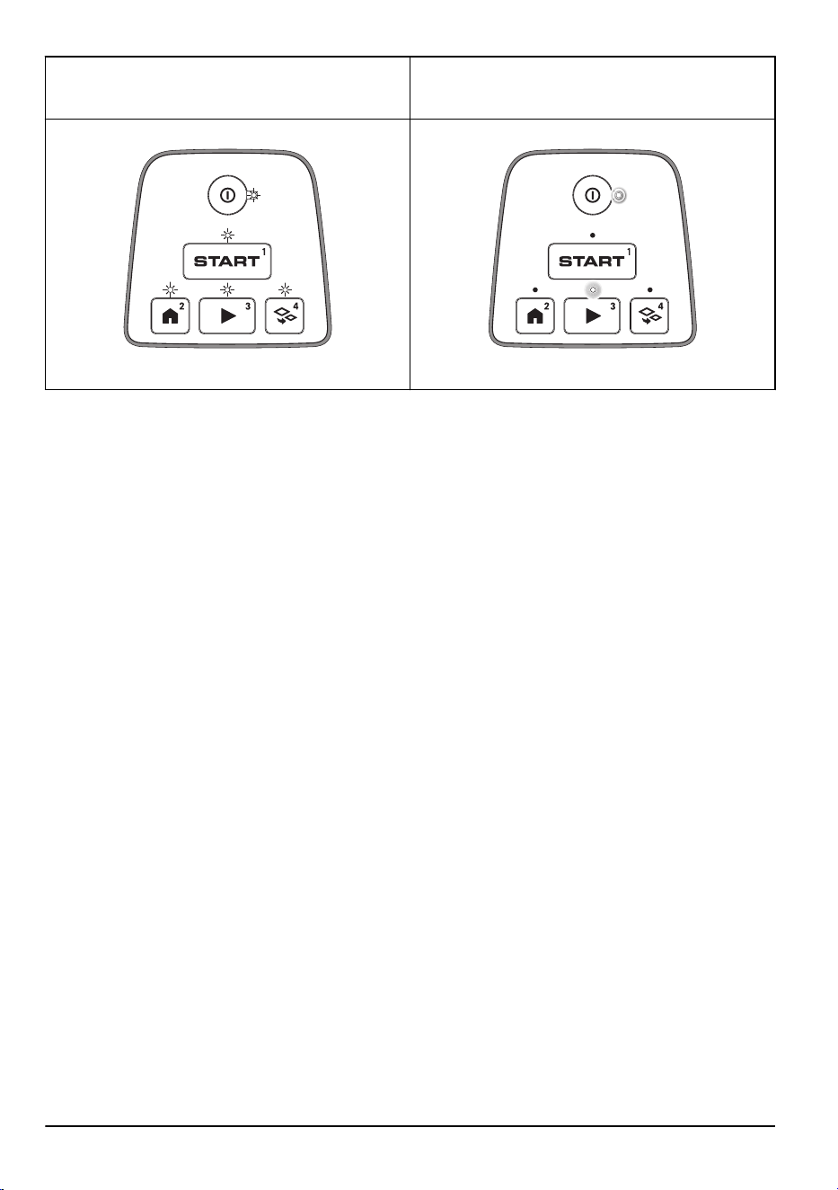
Firmware installation error. The LED indicator flashes
quickly 4 times, stops and then flashes quickly 4 times
again continuously.
Charging
2.8 Product damage
We are not responsible for damages to our product if:
• the product is incorrectly repaired.
• the product is repaired with parts that are not
from the manufacturer or not approved by the
manufacturer.
• the product has an accessory that is not from the
manufacturer or not approved by the manufacturer.
• the product is not repaired at an approved service
center or by an approved authority.
12 - Introduction 1886 - 003 - 12.03.2026
3 Installation
3.1 Introduction - Installation
Refer to www.husqvarna.com for more information
about installation and instruction videos.
We recommend you to update the firmware before you
install the product to make sure that the product has the
latest firmware. Refer to
Download firmware over the air
(Firmware over the air FOTA) on page 24
.
WARNING: Read and understand the
safety chapter before you install the product.
CAUTION: Use original spare parts and
installation material.
3.2 Primary components for installation
The installation involves the following components:
• A robotic lawn mower that mows the lawn
automatically.
• A charging station, which has 3 functions:
• To send control signals along the boundary
wire.
• To send control signals along the guide wire
so that the product can follow the guide wire
to specific remote areas in the garden and
can find its way back to the charging station.
• To charge the product.
• A power supply, which is connected to the
charging station and a 100-240V power outlet.
• Loop wire, which is laid around the work area
and around objects and plants that the product
must not run into. The loop wire is used both as
boundary wire and guide wire.
3.3 To prepare for installation
Read the installation chapter before you start the
installation. Prepare the installation carefully to make the
product operate satisfactorily.
• Make a blueprint of the work area and include all
obstacles. This makes it easier to examine where
to put the charging station, the boundary wire and
the guide wire.
• Make a mark on the blueprint where to put the
charging station, the boundary wire and the guide
wire.
• Make a mark on the blueprint where the guide wire
connects to the boundary wire. Refer to
To install
the guide wire on page 19
.
• Fill in holes in the lawn to make the ground level.
CAUTION:
Holes with water in
the lawn can cause damage to the
product.
• Make sure that the product has Wi-Fi coverage
when it is in the charging station. Refer to
Download firmware over the air (Firmware over the
air FOTA) on page 24
.
Note: New firmware only downloads when the
product is in the charging station.
• Make sure that you have Wi-Fi coverage in the
work area if you use the Automower
®
Connect app
remotely. Refer to
Automower
®
Connect on page
7
.
Note: We recommend you to have Wi-Fi
coverage in the work area. If you have Wi-Fi
coverage, you can control and make settings
for the product remotely with the Automower
®
Connect app. The product automatically connects
to Wi-Fi when it is in an area that has Wi-Fi
coverage.
• Cut the grass before you install the product. Make
sure that the grass is maximum 4 cm / 1.6 in.
Note: The first weeks after installation the sound level
when the product cuts the grass can be higher than
usual. The sound level decreases after some time.
3.4 Before the installation of the wires
You can select to attach the wires with stakes or bury
them. You can use the 2 procedures for the same work
area.
CAUTION:
If you use a dethatcher
in the work area, bury the boundary wire
and the guide wire to prevent them from
damage.
3.4.1 To examine where to put the charging
station
• Keep a minimum 2 m / 6.6 ft. of free space in front
of the charging station. Refer to
To examine where
to put the guide wire on page 17
.
• Keep a minimum of 30 cm / 12 in. of free space
to the right and left of the center of the charging
station.
1886 - 003 - 12.03.2026
Installation - 13
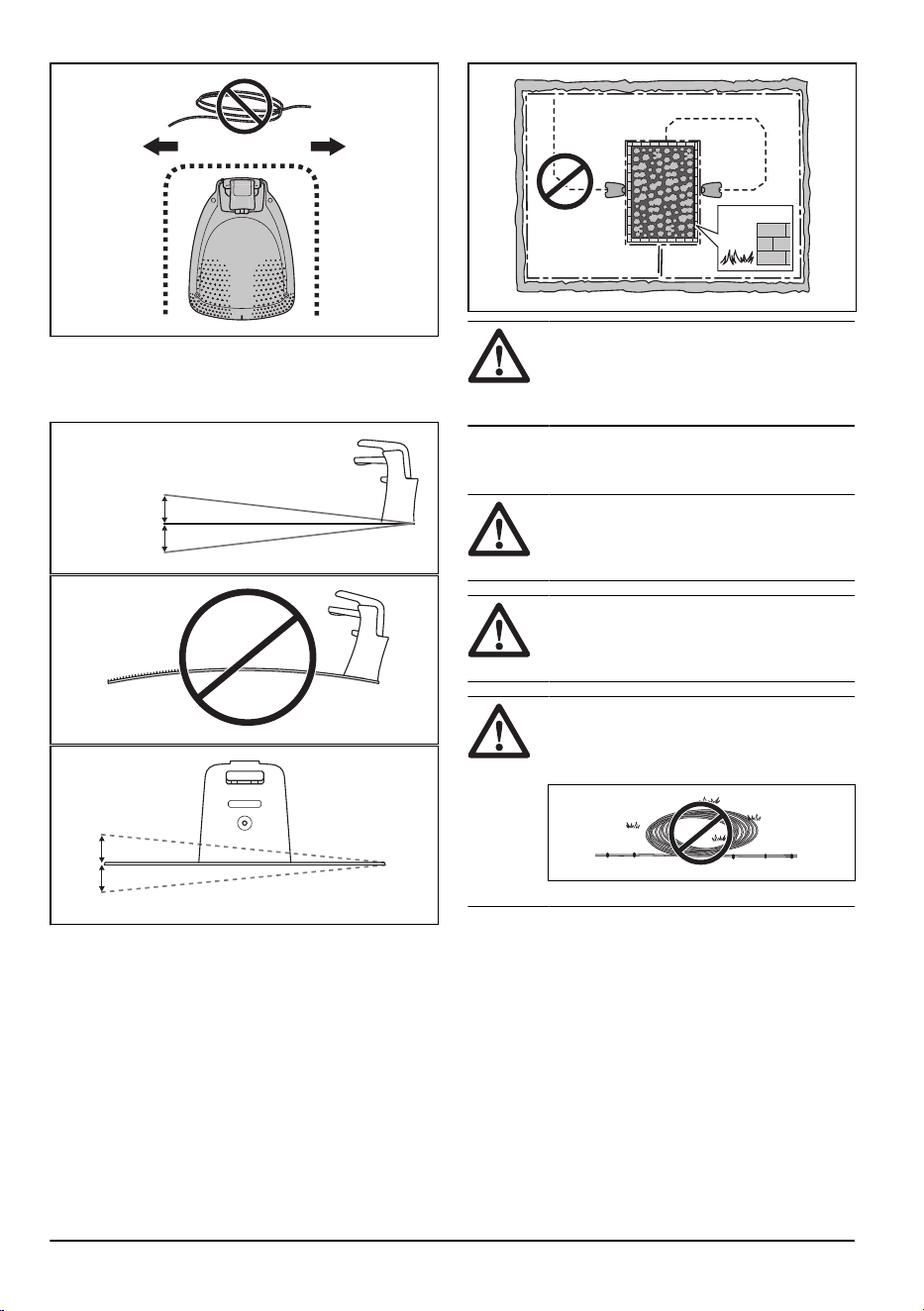
60- cm / 24- in.
• Put the charging station near a power outlet.
• Put the charging station on a level surface.
• The baseplate of the charging station must not be
bent.
Max 3 cm/1.2"
Max 3 cm/1.2"
Max +/- 2 cm / 0.8 in.
• If the work area has two parts separated with a
steep slope, we recommend to put the charging
station in the lower section.
• Put the charging station in an area with protection
from the sun.
• Put the charging station where there is Wi-Fi
coverage to download new firmware. Refer to
Download firmware over the air (Firmware over the
air FOTA) on page 24
.
• If the charging station is installed on an island,
make sure to connect the guide wire to the island.
Refer to
Mowing technique on page 7
.
CAUTION:
Do not install the charging
station where there are metal objects
in the ground. Metal objects can cause
interference with the charging station signal.
3.4.2 To examine where to put the power
supply
WARNING: Do not cut or extend
the low-voltage cable. There is a risk of
electrical shock.
CAUTION: Make sure that the blades
on the product do not cut the low-voltage
cable.
CAUTION: Do not put the low-voltage
cable in a coil or below the charging station
plate. The coil causes interference with the
signal from the charging station.
• Put the power supply in an area with a roof and
protection from the sun and rain.
• Put the power supply in an area with good airflow.
• Use a residual-current device (RCD) with a tripping
current of maximum 30 mA when you connect the
power supply to the power outlet.
Low-voltage cables of different lengths are available as
accessories.
14
- Installation 1886 - 003 - 12.03.2026
3.4.3 To examine where to put the
boundary wire
CAUTION: There must be a barrier of
minimum 15 cm / 6 in. in height between
the boundary wire and water bodies, slopes,
precipices or public roads. This will prevent
damage to the product.
CAUTION: Do not let the product
operate on gravel.
CAUTION: Do not make sharp bends
when you install the boundary wire.
CAUTION: For careful operation
without noise, isolate all obstacles such as
trees, roots and stones.
The boundary wire should be put as a loop around the
work area. Sensors in the product senses when the
product approaches the boundary wire, and the product
selects another direction. All parts of the work area must
be maximum 15 m / 50 ft. from the boundary wire.
To make the connection easier between the guide wire
and the boundary wire, it is recommended to make an
eyelet where the guide wire will be connected. Make the
eyelet with approximately 20 cm / 8 in. of the boundary
wire.
Note:
Make a blueprint of the work area before you
install the boundary wire and guide wire.
A
B
C
E
D
F
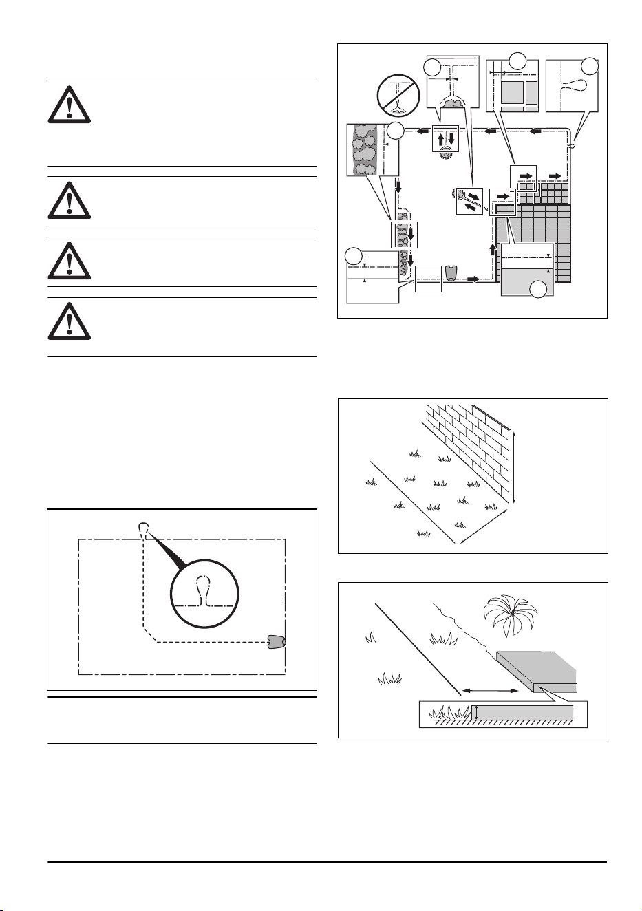
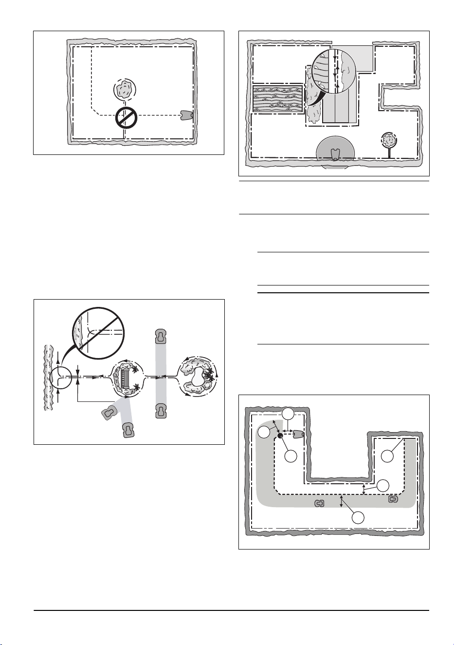
• Put the boundary wire around all of the work area
(A). Adapt the distance between the boundary wire
and obstacles.
• Put the boundary wire 35 cm / 14 in. (B) from an
obstacle that is more than 3.5 cm / 1.4 in. high.
35 cm /14
"
> 3.5 cm / 1.4
"
• Put the boundary wire 30 cm / 12 in. (C) from an
obstacle that is 1-3.5 cm / 0.4-1.4 in. high.
1-3.5 cm / 0.4-1.4"
30 cm / 12"
• Put the boundary wire 10 cm / 4 in. (D) from an
obstacle that is less than 1 cm / 0.4 in. high.
1886 - 003 - 12.03.2026
Installation - 15
10 cm / 4"
max 1 cm / 0.4"
• If you have a paving stone path that is in level with
the lawn, put the boundary wire below the paving
stone.
Note: If the paving stone is minimum 30 cm / 12
in. wide, use the factory setting for the
Drive Past
Wire
function to cut all the grass adjacent to the
paving stone. Refer to
Drive Past Wire function on
page 23
.
• If you make an island, put the boundary wire that
runs to and from the island near together (E). Put
the wires in the same stake. Refer to
To make an
island on page 16
.
• Make an eyelet (F) where the guide wire is to be
connected to the boundary wire.
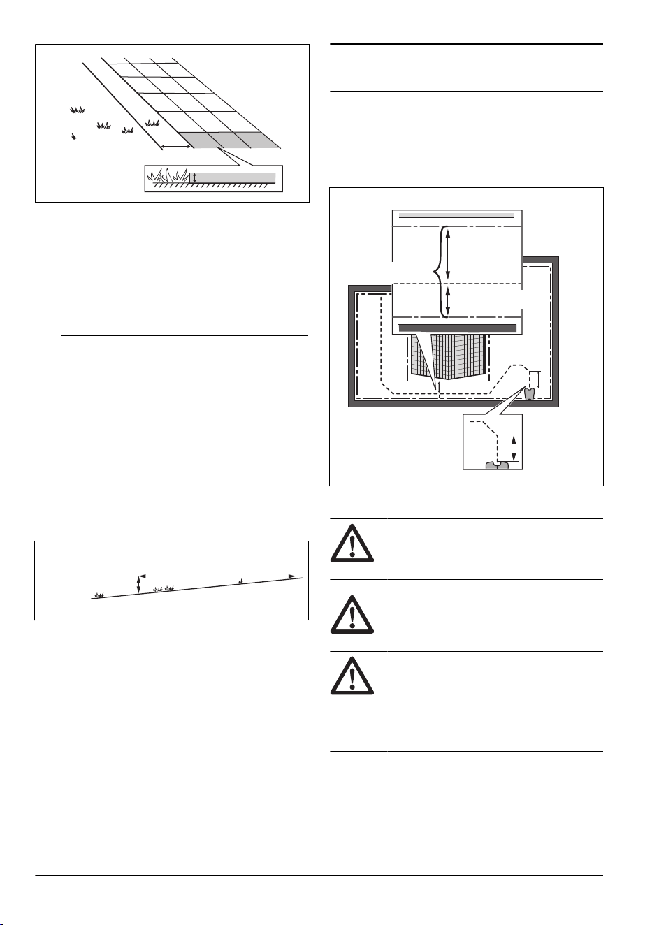
3.4.3.1 To put the boundary wire in a slope
Slopes that are too steep must be isolated with the
boundary wire. The gradient (%) is calculated as the
vertical height divided by the horizontal distance.
Example:
• 10 cm / 100 cm = 10%.
• in / in = 10%.
10 cm/ 4"
100 cm/ 40"
10%
• For slopes that are too steep inside the work area,
isolate the slope with boundary wire.
• For slopes steeper than 10% along the outer edge
of the lawn, put the boundary wire 20 cm / 8 in. (A)
from the edge.
• For slopes adjacent to a public road, put a barrier
of minimum 15 cm / 6 in. along the outer edge of
the slope. You can use a wall or a fence as a
barrier.
3.4.3.2 Passages
A passage is a section that has boundary wire on each
side and that connects 2 parts of the work area. The
distance between the boundary wire on each side in the
passage must be a minimum of 60 cm / 24 in.
Note:
If a passage is less than 2 m / 6.5 ft. wide,
install a guide wire through the passage.
The recommended minimum distance between the
guide wire and the boundary wire is 30 cm / 12 in. The
product always runs to the left of the guide wire as seen
facing the charging station. It is recommended to have
as much free area as possible to the left of the guide
wire (A).
>2 m / 6.5 ft
A
>30 cm / 12"
>60 cm / 24"
3.4.3.3 To make an island
CAUTION:
Do not put the boundary
wires across each other. The sections of
boundary wire must be parallel.
CAUTION: Do not put the guide wire
across the boundary wire.
CAUTION: Isolate or remove obstacles
that are less than 15 cm / 5.9 in. in height.
Isolate or remove obstacles that slope
slightly, for example, stones, trees or roots.
This will prevent damage to the blades of the
product.
16 - Installation 1886 - 003 - 12.03.2026
To make an island, isolate areas in the work area with
the boundary wire. We recommend to isolate all stable
objects in the work area.
Some obstacles are resistant to a collision, for example,
trees or bushes that are more than 15 cm / 5.9 in. in
height. The product will collide with the obstacle and
then select a new direction.
• Put the boundary wire to and around the obstacle
to make an island.
• Put the 2 sections of boundary wire to and from the
island close together. This will make the product
run across the wire.
• Put the 2 sections of boundary wire in the same
stake.
0 cm / 0
"
3.4.3.4 To make a secondary area
Make a secondary area (B) if the work area has 2 areas
that are not connected with a passage. The work area
with the charging station is the main area (A).
B
A
Note:
The product must be manually moved between
the main area and the secondary area.
• Put the boundary wire around the secondary area
(B) to make an island. Refer to
To make an island
on page 16
.
Note: The boundary wire must be put as 1 loop
around all of the work area (A + B).
Note: When the product cuts grass in the
secondary area, the
Secondary area
mode must
be selected. Refer to
Secondary area on page
25
.
3.4.4 To examine where to put the guide
wire
Put the guide wire from the charging station through the
work area and connect it to the boundary wire.
F
D
C E
A
B
• Put the guide wire in a line at a minimum of 1 m /
3.3 ft. in front of the charging station (A).
• Put the guide wire minimum 30 cm / 1 ft. from the
boundary wire (B).
1886 - 003 - 12.03.2026
Installation - 17
• Starting point (C). Refer to
To set the charging
station starting point on page 23
.
• Minimum distance 60 cm / 2 ft. from the starting
point to perpendicular to the boundary wire (D).
Refer to
To install the guide wire on page 19
.
• Where the guide wire is connected to the boundary
wire (E).
• Guide corridor (F). The product always runs to the
left of the guide wire as seen facing the charging
station. Make sure that the guide wire has as much
free area as possible to the left of the guide wire.
The guide corridor can be maximum 1.2 m / 4 ft.
Note: The product always runs in the guide
corridor but changes the distance to the guide
wire.
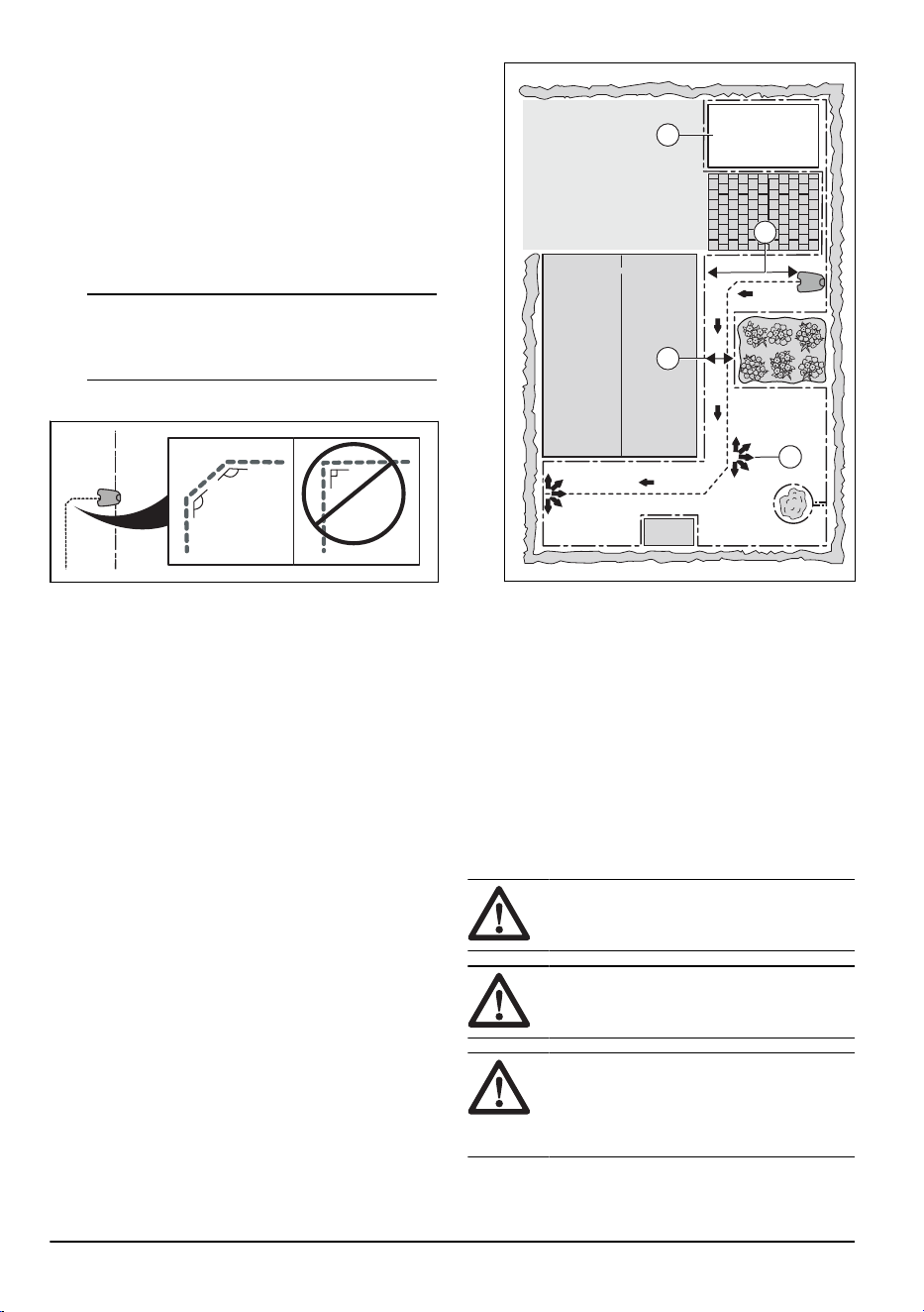
• Do not make sharp bends when you install the
guide wire.
135º
135º
90º
3.4.5 Work area examples
• If the charging station is put in a small area (A),
make sure that the distance to the boundary wire is
at a minimum 2 m / 6.6 ft. in front of the charging
station.
• If the work area has a passage (B) with no guide
wire installed, the minimum distance between the
boundary wires is 2 m / 6.5 ft. With a guide
wire installed through the passage, the minimum
distance between the boundary wires is 60 cm / 24
in.
• If the work area has areas which are connected
by a narrow passage (B), you can set the product
to first follow and then leave the guide wire
after a certain distance (C). The settings can
be changed in
Lawn Coverage and Systematic
Passage Mowing on page 23
.
• If the work area includes a secondary area
(D), refer to
Secondary area on page 25
. Put
the product in the secondary area and select
Secondary area mode
.
B
D
C
A
3.5 Installation of the product
3.5.1 Installation tools
• Hammer/plastic mallet: To simplify putting the
stakes into the ground.
• Edge cutter/straight spade: To bury the boundary
wire.
• Combination pliers: For cutting the boundary wire
and pressing the connectors together.
• Adjustable plier: For pressing the couplers
together.
3.5.2 To install the charging station
CAUTION: Do not make new holes in
the charging station plate.
CAUTION: Do not put your feet on the
baseplate of the charging station.
WARNING: Make sure that the plugs of
the low-voltage cable and the power supply
unit are clean and dry before you connect
them.
18 - Installation 1886 - 003 - 12.03.2026
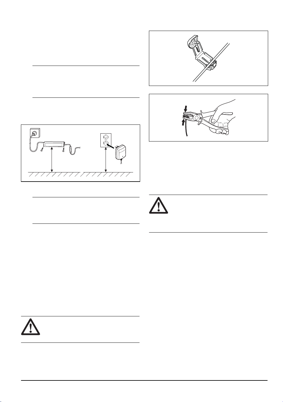
When connecting the power supply, only use a power
outlet that is connected to an residual-current (RCD)
device.
1. Read and understand the instructions about the
charging station. Refer to
To examine where to put
the charging station on page 13
.
2. Put the charging station in the selected area.
Note: Do not attach the charging station to the
ground with the screws until the guide wire is
installed. Refer to
To install the guide wire on page
19
.
3. Connect the low-voltage cable to the charging
station and to the power supply unit.
4. Put the power supply at a minimum height of 30
cm / 12 in.
min 30 cm / 12”
5. Connect the power supply cable to a 100-240V
power outlet.
Note: The product can be put in the charging
station to charge while you install the boundary
wire and the guide wire.
6. Put the low-voltage cable in the ground with stakes
or bury the cable. Refer to
To put the wire or the
cable into position with stakes on page 20
or
To
bury the wire or the cable on page 20
.
7. Connect the wires to the charging station after
the installation of boundary wire and guide wire is
complete. Refer to
To install the boundary wire on
page 19
and
To install the guide wire on page
19
.
8. Attach the charging station to the ground with the
supplied screws after the guide wire is installed.
Refer to
Safety instructions for operation on page
4
.
3.5.3 To install the boundary wire
CAUTION:
Do not put remaining wire in
a coil. The coil causes interference with the
product.
1. Put the boundary wire around all of the work
area. Start and complete the installation behind the
charging station.
2. Open the connector and put the boundary wire in
the connector.
3. Close the connector with a pair of pliers.
4. Cut the boundary wire 1-2 cm / 0.4-0.8 in. above
each connector.
5. Push the right connector onto the metal pin on the
charging station with the mark "R".
6. Push the left connector onto the metal pin on the
charging station with the mark "L".
3.5.4 To install the guide wire
CAUTION: Twinned cables, or a
screw terminal block that is insulated with
insulation tape are not satisfactory splices.
Soil moisture will cause the wire to oxidize
and after a time result in a broken circuit.
1. Open the connector and put the wire in the
connector.
2. Close the connector with a pair of pliers.
3. Cut the guide wire 1-2 cm / 0.4-0.8 in. above each
connector.
4. Push the guide wire through the slot in the
charging station plate.
5. Push the connector onto the metal pin on the
charging station with the mark "G".
6. Disconnect the charging station from the power
outlet.
7. Put the end of the guide wire at the eyelet on the
boundary wire.
8. Cut the boundary wire with a pair of wire cutters.
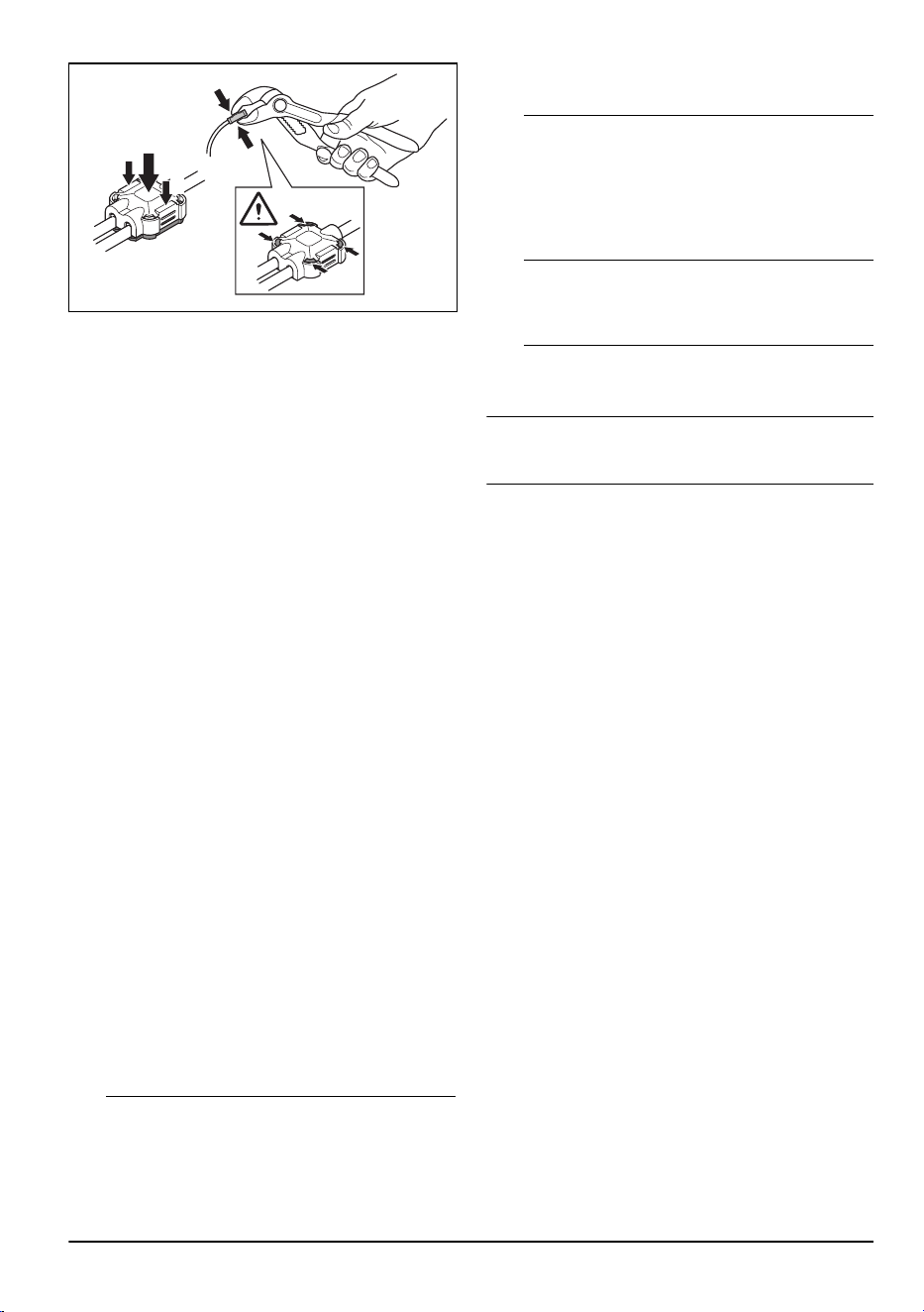
9. Connect the guide wire to the boundary wire with a
coupler.
1886 - 003 - 12.03.2026
Installation - 19
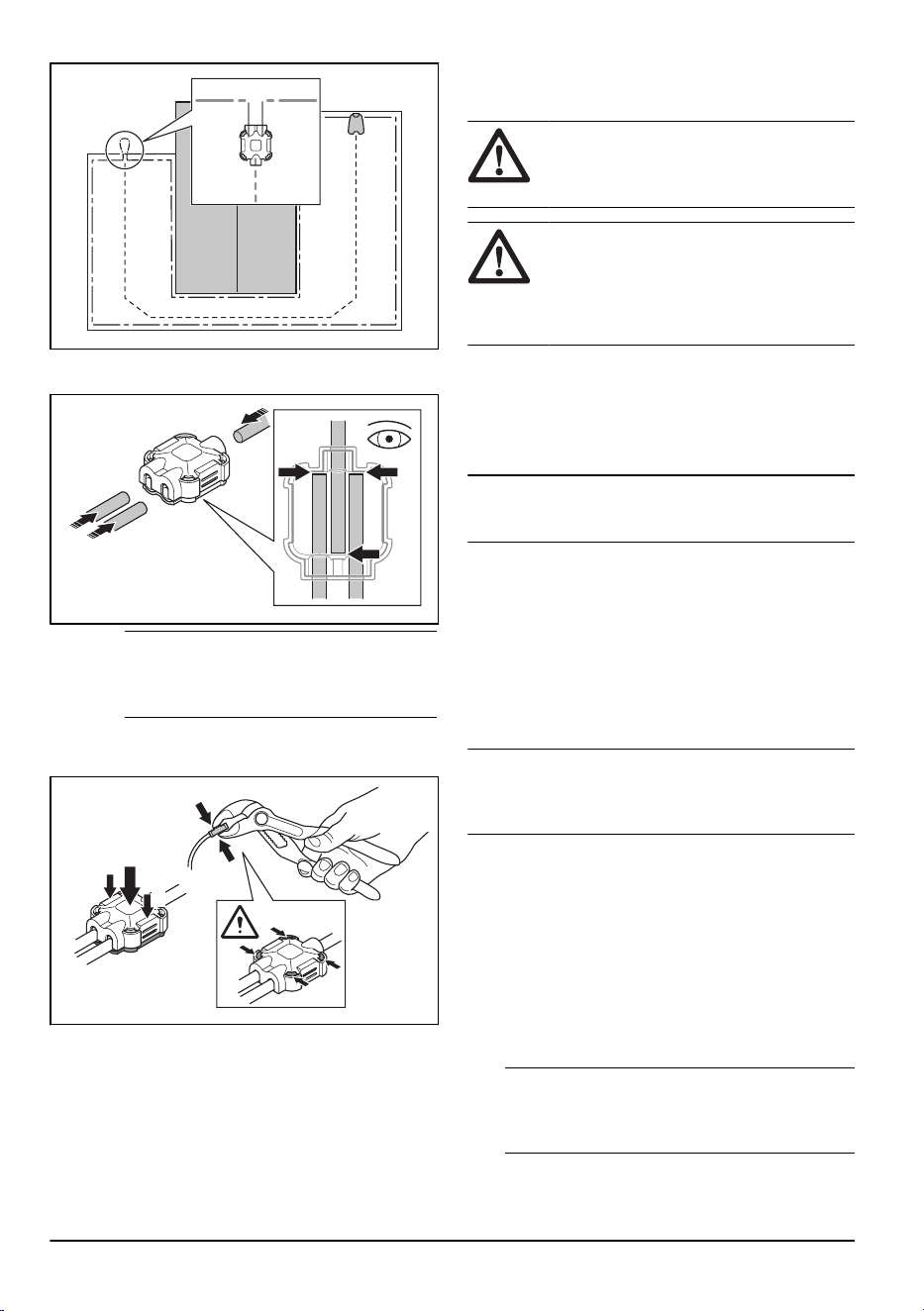
a) Put the 2 ends of the boundary wire and the
end of the guide wire fully into the coupler.
Note: Make sure that you have put the
wires fully into the coupler for a correct
installation.
b) Push down the cover on the coupler with
adjustable pliers to attach the wires in the
coupler.
1
2
2
10. Attach the guide wire to the ground with stakes or
bury the guide wire in the ground. Refer to
To put
the wire or the cable into position with stakes on
page 20
or
To bury the wire or the cable on page
20
.
11. Connect the charging station to the power outlet.
3.6 To put the wire or the cable into
position with stakes
CAUTION: Make sure that the stakes
hold the wire or the cable against the
ground.
CAUTION: Cutting the grass too low
right after installation can damage the wire
or the cable insulation. Damage to the
insulation may not cause disruptions until
several weeks or months later.
1. Put the wire or the cable on the ground.
2. Put the stakes at a maximum of 75 cm / 30 in.
distance from each other.
3. Attach the stakes to the ground with a hammer or a
plastic mallet.
Note: The wire or the cable is overgrown with grass
and not visible after a few weeks.
3.7 To bury the wire or the cable
• Cut a groove in the ground with an edge cutter or a
straight shovel.
• Put the wire or the cable 1-20 cm / 0.4-8 in. into the
ground.
3.8 To extend the boundary wire or the
guide wire
Note:
Extend the boundary wire or the guide wire if it
is too short for the work area. Use original spare parts,
for example couplers.
1. Disconnect the charging station from the power
outlet.
2. Cut the boundary wire or the guide wire with a pair
of wire cutters where it is necessary to install the
extension.
3. Add wire where it is necessary to install the
extension.
4. Put the boundary wire or the guide wire into
position.
5. Put the wire ends into a coupler.
Note:
Make sure that you can see the ends of
the boundary wire or the guide wire through the
transparent area of the coupler.
6. Push down the cover on the coupler with
adjustable pliers to attach the wires in the coupler.
20
- Installation 1886 - 003 - 12.03.2026
1
2
2
7. Put the boundary wire or the guide wire into
position with stakes.
8. Connect the charging station to the power outlet.
3.9 After the installation of the product
3.9.1 To do a visual check of the charging
station
1. Make sure that the indicator LED lamp on the
charging station has a green light. Refer to
Indicator lamp in the charging station on page 38
for information about the LED indicator.
2. If the indicator LED lamp does not have a green
light, do a check of the installation. Refer to
Indicator lamp in the charging station on page 38
and
To install the charging station on page 18
.
3.10 To install the Automower
®
Connect app
1. Download the Automower
®
Connect app on your
mobile device.
2. Sign up for a Husqvarna account in the
Automower
®
Connect app.
3. An e-mail is sent to the registered e-mail address.
Follow the instructions in the e-mail in less than 24
hours to validate your account.
4. Log in to your Husqvarna account in the
Automower
®
Connect app.
3.11 To start the product for the first
time
1. Push the ON/OFF button for 3 seconds to set the
product to ON. Enter the PIN code when the LED
indicators flashes. Refer to
PIN code on page 24
.
2. Use the keypad on the product to enter the factory
PIN code 1234.
Note:
The Bluetooth
®
pairing operation mode
of the product is enabled for 3 minutes. If the
pairing operation between the product and the
mobile device is not completed correctly, restart
the product to enable Bluetooth
®
again.
3. Log on to your Husqvarna account in the
Automower
®
Connect app.
4. Start Bluetooth
®
on your mobile device.
5. Select
My mowers
in the Automower
®
Connect
app, and add your product.
6. Enter the factory PIN code 1234 in the app.
Note: We recommend that you change the
factory PIN code to a personal PIN code. Refer to
PIN code on page 24
.
7. Follow the instructions in the app to make settings,
select your Wi-Fi network and to connect to
Husqvarna Cloud.
Note: It is only necessary to do a pairing operation of
the Automower
®
Connect app and the product one time.
1886 - 003 - 12.03.2026 Installation - 21
4 Settings
Use the Automower
®
Connect app for product settings.
The factory settings are applicable for almost all work
areas, but the settings can be adapted to the conditions
for each work area.
4.1 Schedule
In
Schedule
you can change the schedule settings for
the product.
The
Schedule
function controls which hours the product
operates. When the product does not operate, it is
parked in the charging station. You can see which hours
and days the product operates in the schedule overview
in the app.
You can set the Schedule if the work area is less
than the maximum area capacity of the product. This
prevents wear on the grass and the product. The factory
schedule setting lets the product operate around the
clock 7 days a week.
To calculate the schedule setting, refer to
Schedule on
page 22
.
4.1.1 Make an estimate of the necessary
operating time
If the work area is less than maximum product capacity,
the schedule must be set to decrease the wear on the
lawn and the product. The product has a maximum
cutting time each day. You can set the operating time of
the product in the schedule. The operating time includes
cutting, searching and charging. The operating time can
be different because of many reasons, for example the
layout of the work area, the grass growth and age of the
battery. When the product has operated to the maximum
cutting time in a day, the message
Today's mowing
complete
is shown in the display of the app.
The recommended operating times for some work area
examples are shown in the table below. If the result is
not satisfactory, increase the operating time.
Area, m
2
Recommended operating
time, h
200 5-6
400 11-12
4.2 Operation
In
Operation
you can change the operation settings of
the product.
4.2.1 Weather timer
Weather timer
automatically adjust the cutting time to
the growth of the grass. The product is not permitted to
operate more than the schedule settings.
Note: When using
Weather timer
, it is recommended
to make as much operating time as possible available
for
Weather timer
. Do not restrict the schedule more
than necessary.
The first operation of the day is set by the schedule
settings. The product always complete 1 mowing cycle,
and then
Weather timer
selects if the product will
continue to operate or not.
Note:
Weather timer
is reset if the product does not
operate for more than 50 hours, or if a
Reset of all user
settings
is done.
Weather timer
is not changed if a
Reset
of schedule settings
is done.
4.2.2 ECO mode
ECO mode
disables the signal in the boundary wire,
guide wire and the charging station, when the product is
parked or is charging. The LED indicator of the charging
station flashes green when the loop signal is disabled.
Note: Use
ECO mode
to save energy and to prevent
interference with other equipment, for example hearing
loops or garage doors.
Note: To start the product manually in the work area
you must first enable the loop signal.
4.2.2.1 To enable the loop signal
1. Set the product to ON.
2. Put the product in the charging station.
3. Push the STOP button.
4. Wait 2 seconds and then remove the product from
the charging station.
5. Make sure that the LED indicator of the charging
station is solid green.
6. Put the product where you want it to start to cut.
4.2.3 Frost Guard
The grass is more sensitive to wear if there is frost on
the grass. If the
Frost Guard
is enabled, the product
22
- Settings 1886 - 003 - 12.03.2026
does not start to cut the grass if the temperature is less
than 5° C / 41° F.
Note: The frost sensor is at the inner side of
the chassis. There can be a temperature difference
compared to the ambient temperature.
4.3 Installation
In
Installation
you can change the installation settings of
the product.
4.3.1 Lawn Coverage and Systematic
Passage Mowing
If the work area includes remote parts that are
connected with narrow passages, the
Lawn Coverage
and
Systematic Passage Mowing
function are useful to
be able to maintain a well-cut lawn in all parts of the
yard. The
Lawn Coverage
function is used to guide
the product to remote parts of the work area. The
Systematic Passage Mowing
function is used for narrow
passage mowing. A guide wire must be installed to use
these functions. You can set a maximum of 3 remote
areas.
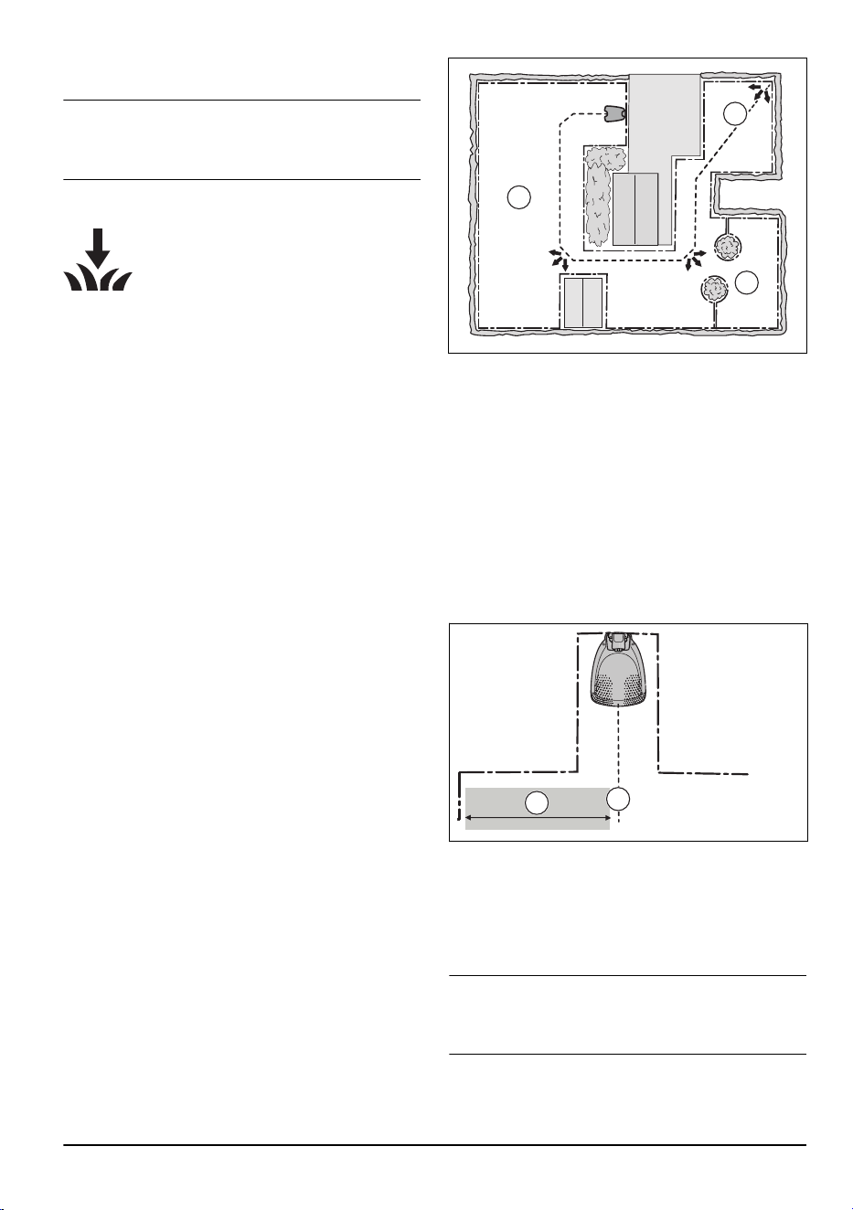
With the
Lawn Coverage
function the product first
follows and then leaves the guide wire after a certain
distance and starts to mow the lawn.
The
Systematic Passage Mowing
function is suitable
to mow narrow passages of 60 cm - 1.5 m / 2 in. -
4.9 ft. width. The product moves in a pattern to cover
the passage width. The product starts the
Systematic
Passage Mowing
at the set distance from the charging
station. When the product reaches the end of the narrow
passage, the product continues and cuts the lawn as
normal.
Area A, approximately 50%
Area B, approximately 30%
Area C, approximately 20%
A
C
B
4.3.2 To set the charging station starting
point
The product starts to operate at the starting point. The
starting point is set to control how far the product
moves along the guide wire from the charging station.
The product straddles the guide wire from the charging
station to the starting point. The factory setting is 60 cm /
2 ft.
• Set the starting point at a short distance from the
charging station to prevent tracks on the lawn.
• If the charging station is put in a small area, set the
starting point (A) where the minimum distance (B)
to the boundary wire is 60 cm / 2 ft.
B
A
4.3.3 Drive Past Wire function
The front of the product always moves past the
boundary wire by a specified distance. Then the product
moves rearward and changes direction. The factory
setting is 32 cm / 12 in. You can select a distance of
25–35 cm / 10–14 in.
Note:
If you change the distance for
Drive Past Wire
,
the distance will change along the boundary wire in all
parts of the work area.
1886 - 003 - 12.03.2026 Settings - 23
4.4 Accessories
In
Accessories
you can change the settings of the
product accessories.
4.4.1 Avoid collisions with Husqvarna
mower house
If you have installed a Husqvarna mower house
9
, the
wear on the product and the mower house decreases
when you select
Avoid house collisions
. In the factory
setting this function is disabled.
Note: If
Avoid house collisions
is selected it can result
in grass that is not cut around the charging station.
4.4.2 FlexiFence
If you install the FlexiFence accessory, you must enable
the FlexiFence function in the Automower
®
Connect
app.
4.5 General
In the
General
menu you can set the time and date, or
reset to factory settings.
This menu is only available when your mobile device is
connected to the product with Bluetooth
®
.
4.5.1 Time & date
The time and date can be changed manually, or by
using the time and date from the mobile device.
4.5.2 Reset to factory settings
The user settings can be reset to factory settings.
Note:
PIN code, Loop signal, Messages
and
Date &
Time
will not be reset.
4.6 Safety
In the
Safety
menu you can set the safety settings of the
product.
4.6.1 New loop signal
The loop signal is randomly selected to create a unique
link between the product and the charging station. In
rare cases, there may be a need to generate a new
signal, for instance if two adjacent installations have
a very similar signal. Put the product in the charging
station before you make a new loop signal.
4.6.2 PIN code
When you use the product for the first time you must
enter the factory PIN code 1234. You can change the
PIN code in the app. The PIN code must have 4 digits.
You can use the numbers 1-4 to set a new PIN code.
Refer to
Keypad on page 9
.
4.7 Automower
®
Connect
In
Automower
®
Connect
you can connect the product to
a Wi-Fi network. You can also see the signal strength
and connectivity status.
This menu is only available when your mobile device is
connected to the product with Bluetooth
®
.
4.8 Download firmware over the air
(Firmware over the air FOTA)
The product has a function that automatically downloads
new firmware. The product downloads new firmware
when it is parked in the charging station and has
Wi-Fi coverage. When a new firmware is available, a
notification shows in the app where you can select to
install the new firmware.
9
Available as accessory
24 - Settings 1886 - 003 - 12.03.2026
5 Operation
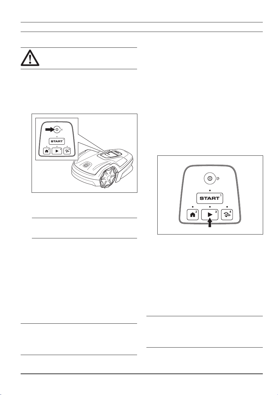
5.1 To use the ON/OFF button
WARNING: Read and understand the
safety chapter before you use the product.
• Push the ON/OFF button for 3 seconds to set the
product to ON. Make sure that the LED indicator
comes on.
• The product is ON and in power save mode if the
LED indicator flashes. To get out of power save
mode, push the ON/OFF button for 3 seconds.
• Push the ON/OFF button for 3 seconds to set the
product to OFF. Make sure that the LED indicator
goes off.
Note:
The product cannot be set to OFF when it
is in the charging station.
5.1.1 The indicator lamp
The indicator lamps on the keypad show the operating
modes of the product, refer to
LED indicator on the
keypad on page 10
.
5.2 To start the product
1. Push the ON/OFF button for 3 seconds.
2. Use the buttons on the keypad to enter the PIN
code and then push the OK button. Refer to
PIN
code on page 24
.
3. Select an operating mode. Refer to
Operating
modes on page 25
.
Note:
The first weeks after installation the perceived
sound level when cutting the grass may be higher than
expected. When the product has cut the grass for some
time, the perceived sound level is much lower.
5.3 Operating modes
The following operating modes are available:
•
Main area
•
Secondary area
•
Park
•
Park / Schedule
•
Override schedule
5.3.1 Main area
Main area
is the standard operating mode where the
product mows and charges automatically.
5.3.1.1 To set the product to operate in Main area
This can be set in the dashboard in the app or with the
keypad on the product:
1. Push the STOP button.
2. Push the Play button.
3. Push the START button.
5.3.2 Secondary area
To mow secondary areas the operating mode
Secondary area
must be selected. In this mode, the
operator must move the product manually between the
main area and the secondary area. The product mows
until the battery is empty. When the battery is empty, put
the product in the charging station to charge the battery.
When the battery is charged, the product moves out
of the charging station and stops. The product is now
prepared to start operation, but needs confirmation from
the operator first.
Note:
Put the product in the charging station and
change the operating mode to
Main area
in the app or
with the keypad on the product if you want to cut the
main area after the battery is charged.
1886 - 003 - 12.03.2026 Operation - 25
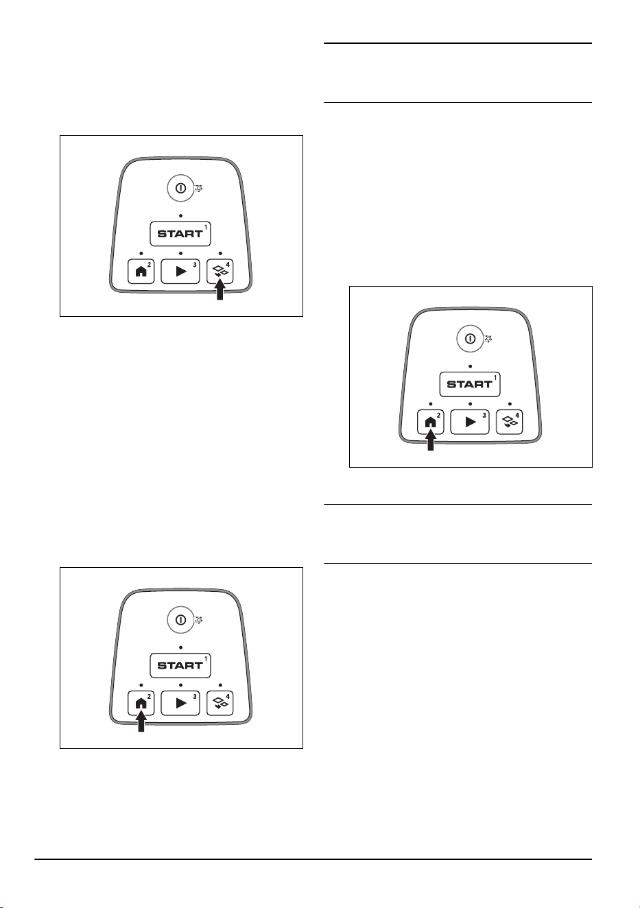
5.3.2.1 To set the product to operate in Secondary area
This can be set in the dashboard in the app or with the
keypad on the product:
1. Push the STOP button.
2. Push the Secondary area button.
3. Push the START button.
5.3.3 Park
Operating mode
Park / Schedule
means that the product
goes back to the charging station where it stays until the
next schedule. If the product has operated the maximum
cutting time for the day, it will start to operate again the
next day. Refer to
Make an estimate of the necessary
operating time on page 22
.
5.3.3.1 To park the product and start again with the next
schedule
This can be set in the dashboard in the app or with the
keypad on the product:
1. Push the STOP button.
2. Push the Park button.
3. Push the START button.
Note:
To change the operating mode of the product,
push the STOP button and the product will be in idle
mode where you can set an operating mode.
5.3.4 Park until further notice
Use the operating mode
Park until further notice
for the
product to go back to the charging station. The product
will stay in the charging station until you select a new
operating mode.
5.3.4.1 To park the product
This can be set in the dashboard in the app or with the
keypad on the product:
1. Push the STOP button.
2. Push the Park button for 2 seconds.
3. Push the START button.
Note:
To change the operating mode of the product,
push the STOP button and the product will be in idle
mode where you can set an operating mode.
5.3.5 Override schedule
Select
Override schedule
to temporarily override the
schedule settings. You can select to override the
schedule settings for 3 hours. The product cannot be
set to cut more than the maximum cutting time for each
day.
5.3.5.1 To override the schedule
This can be set in the dashboard in the app or with the
keypad on the product:
1. Push the STOP button.
2. Push the Play button for 2 seconds.
26
- Operation 1886 - 003 - 12.03.2026
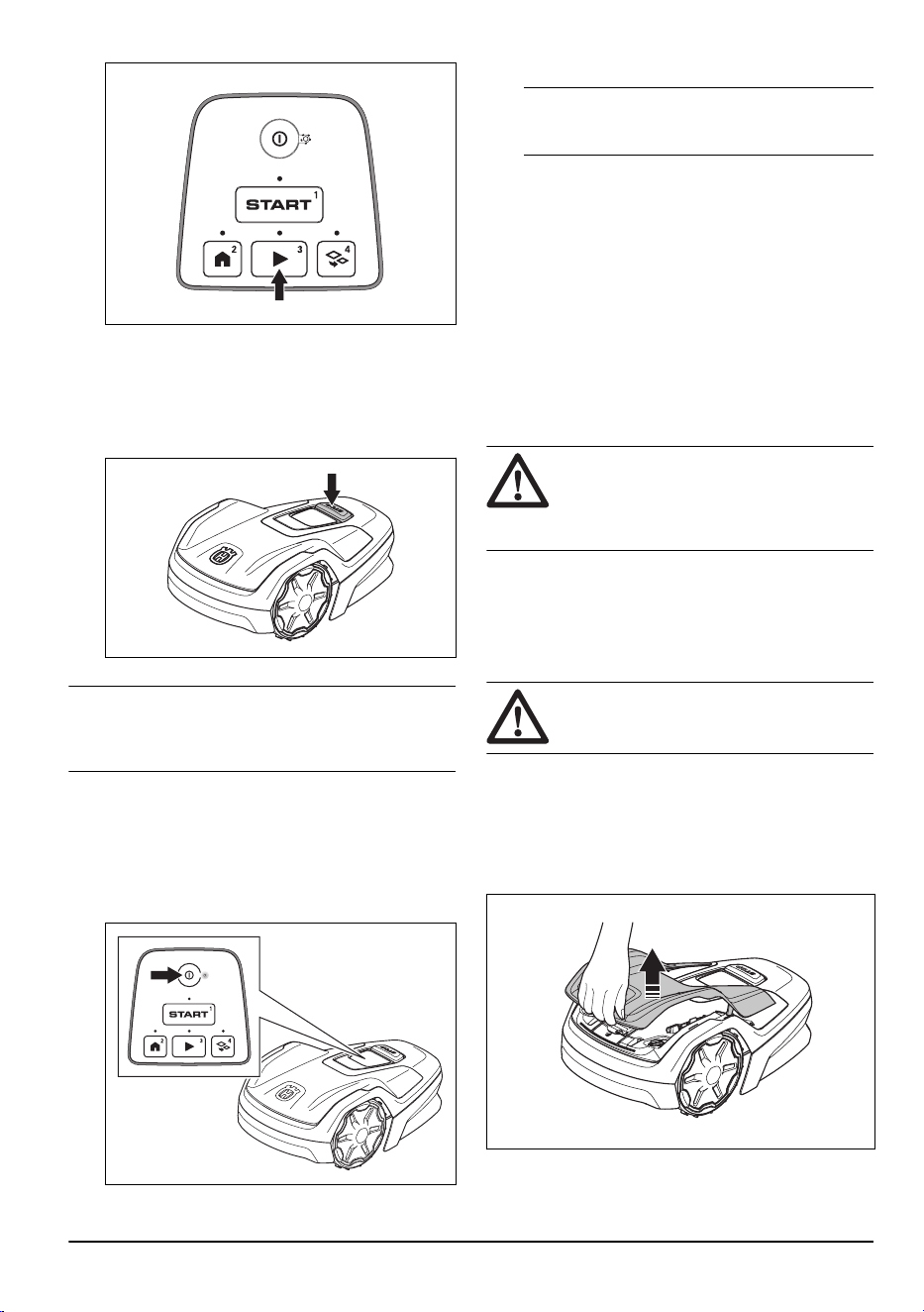
3. Push the START button.
5.4 To stop the product
1. Push the STOP button on top of the product.
Note:
When the STOP button is pushed the product
will be idle. The product stops and the cutting motor
stops.
5.5 To set the product to OFF
1. Push the STOP button.
2. Push the ON/OFF button for 3 seconds to set the
product to OFF. Make sure that the LED indicator
goes off.
Note: The product cannot be set to OFF when it
is in the charging station.
5.6 To charge the battery
When the product is new or after long-term storage, the
battery can be empty. Charge the battery before you
start the product. In the
Main area
mode, the product
cuts and charges automatically.
1. Push the ON/OFF button to start the product.
2. Put the product into the charging station until the
charging plates touch the contact plates.
3. Make sure that the LED on the ON/OFF button
pulsates.
5.7 Cutting height adjustment
CAUTION: The first weeks after a new
installation, set the cutting height to 3 to
prevent damage to the loop wire. You can
then lower the cutting height each week.
You can select between 3 different cutting height steps.
The blade disc has marks for each step. Step 1 is the
lowest height, step 2 is the middle height, and step 3 is
the highest height. The factory setting is set to 3.
5.7.1 To adjust the cutting height
WARNING: Use protective gloves.
1. Push the ON/OFF button for 3 seconds to set the
product to OFF.
2. Make sure that the product is disabled. The LED
indicator on the ON/OFF button is not on when the
product is disabled. Refer to
Keypad on page 9
.
3. Lift the top cover by the front and remove it.
4. Remove the torx key from the body of the product.
5. Put the product with the blade disc up.
1886 - 003 - 12.03.2026
Operation - 27
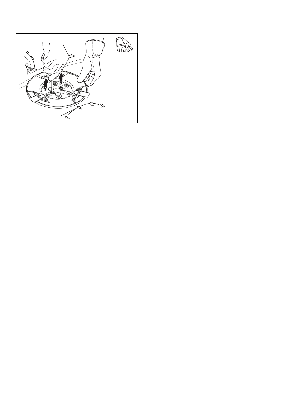
6. Remove the 2 screws on the blade disc.
7. Remove the blade disc.
8. Select a cutting height and align the 2 holes on the
blade disc with the 2 holes on the shaft.
9. Attach the 2 screws on the blade disc to install the
shaft on the blade disc.
10. Attach the torx key on the body of the product.
11. Attach the top cover on the product.
28 - Operation 1886 - 003 - 12.03.2026
6 Maintenance
6.1 Introduction - maintenance
WARNING: Set the product to OFF
before you do maintenance on the product.
WARNING: Use protective gloves.
For better operation and lifetime of the product, make
sure to clean the product regularly and replace worn
parts.
When the product is new, examine the blade discs and
blades each week. If the wear is low, you can increase
the interval for the next time you examine the blade
discs and blades. Examine the blade discs and the
blades more regularly if there is much wear.
It is important that the blade disc rotates easily and that
the edges of the blades are not damaged. The usual
lifetime of the blades are 4 to 7 weeks. The conditions
that follow can increase or decrease the lifetime of the
blades:
• Operation time and dimension of the work area.
• Length and thickness of the grass.
• Soil, sand and use of fertilizers.
• Objects such as cones, tools, stones and roots in
the work area.
Note: The cutting result can be unsatisfactory if the
blades are blunt. Refer to
Replacement of the blades on
page 31
on how to replace the blades.
6.2 Maintenance schedule
The maintenance schedule shows how to do
servicing and maintenance on the product. Follow the
maintenance schedule for a better operation and to
increase the lifetime of the product.
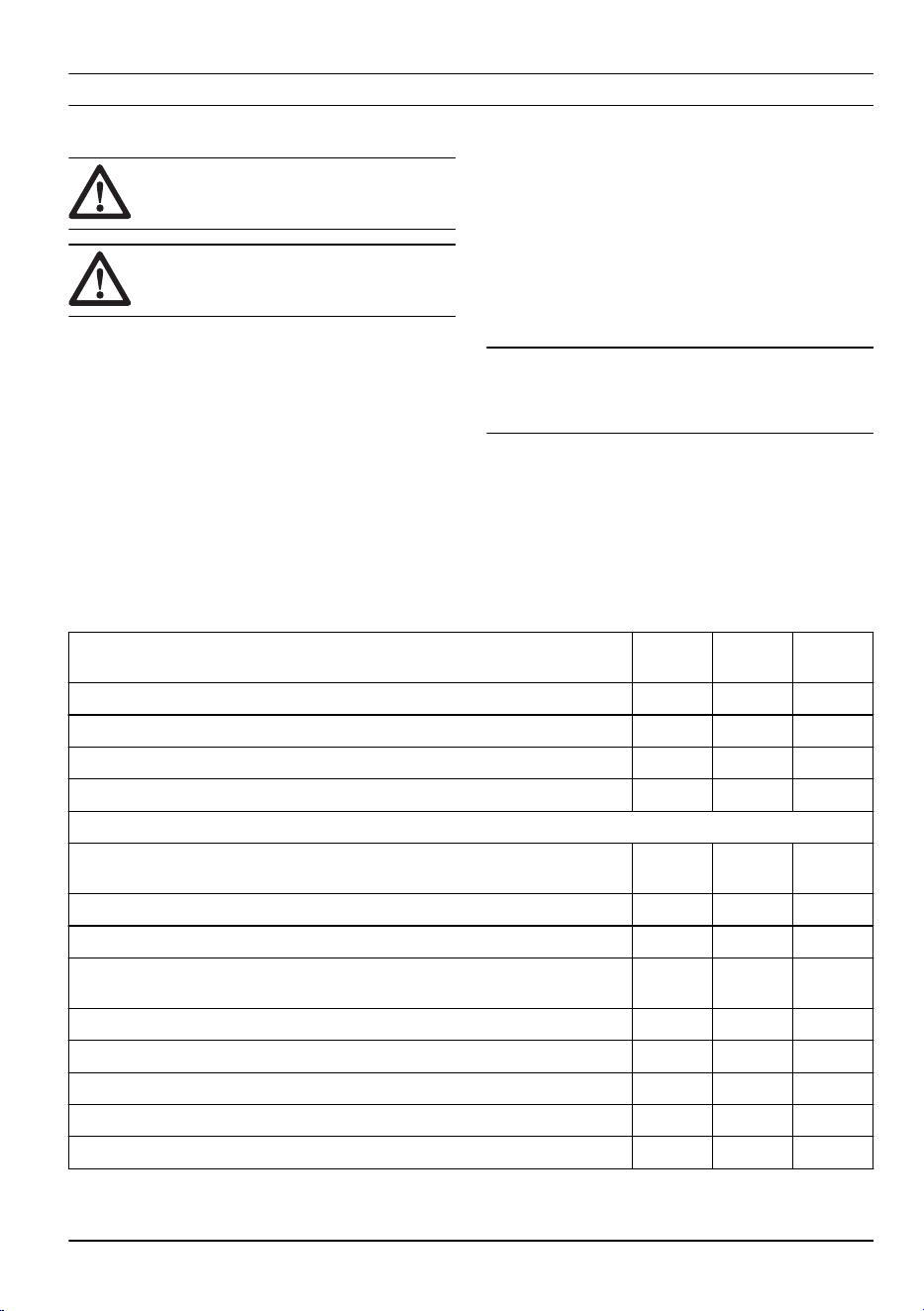
X = The instructions are given in this operator's manual.
O = The instructions are not given in this operator's
manual. Speak to your approved servicing dealer.
To prepare Weekly Every
year
Every
third year
Clean the product. Refer to
Clean the product on page 30
. X
Examine the product for damage and wear. X
Do an update of the firmware. X
Do a check of the servicing messages for recommended upgrades. O
Servicing
Examine the blades and replace the blades and blade screws if it is necessary.
Refer to
Replacement of the blades on page 31
.
X
Examine and polish the contact plates on the charging station. X
Examine and polish the charging plates on the product. X
Charge the battery fully before you put the product into storage. Refer to
To
charge the battery on page 27
.
X
Make sure that the product is docking and charging correctly. O
Examine and clean the airflow filter. O
Replace the airflow filter. O
Do a check of the tightening torque of chassis screws. O
Open the chassis and replace all sealing strips. O
1886 - 003 - 12.03.2026 Maintenance - 29
To prepare Weekly Every
year
Every
third year
Last step
Use a software service tool to do a function test of the functions of the product. O
6.3 Clean the product
CAUTION: Do not use a high-pressure
washer to clean the product. Do not use
solvents for cleaning.
WARNING: Use protective gloves.
Husqvarna recommends to use a special cleaning and
maintenance kit. Speak to your Husqvarna service for
more information.
6.3.1 To clean the chassis and blade disc
Examine the blade discs and blades weekly. Remove
the body of the product to clean it fully.
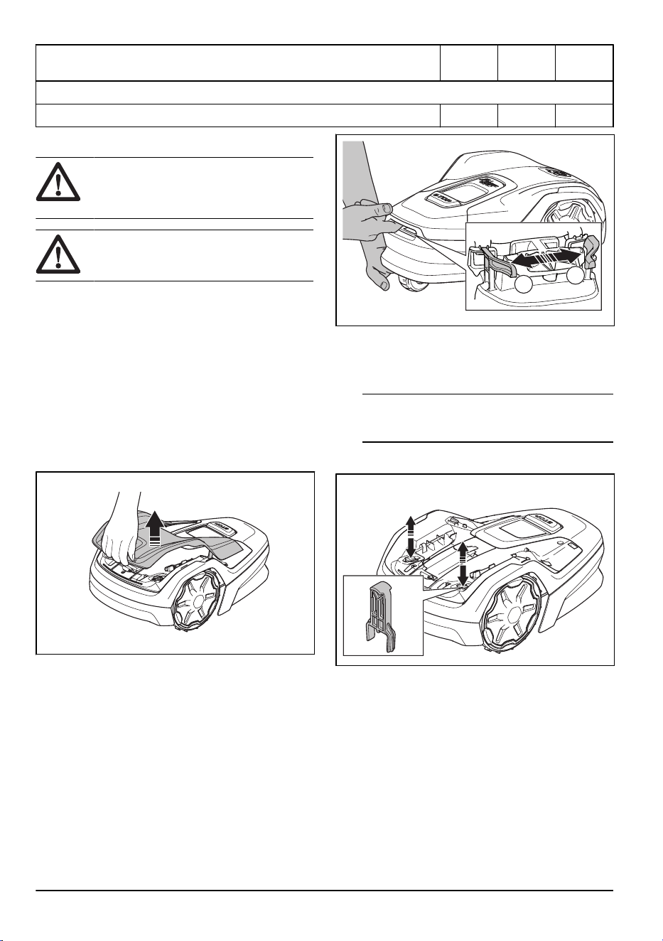
1. Push the STOP button.
2. Push the ON/OFF button for 3 seconds to set the
product to OFF. Make sure that the LED indicator
on the keypad goes out.
3. Lift the top cover by the front and remove it.
4. Remove the maintenance tool from the body of the
product.
5. Hold the rear wheel with one hand.
A
B
6. Push the back of the hand up to lift the body of the
product.
7. With your other hand, push the left clip (A) and
then the right clip (B).
Note: You cannot see the clip (A) and (B). You
find the clips in the hole at the front of the product.
8. Push the maintenance tool into the 2 holes to
loosen the body of the product.
9. Remove the body of the product.
10. Put the product onto its side.
11. Make sure that the blades are not damaged and
that the blades and blade discs can rotate freely.
12. Clean the blade discs and chassis with a brush
and running water.
6.3.2 To clean the wheels
The product does not operate satisfactorily in slopes if
the wheels are blocked with grass.
• Use a soft brush to clean the wheels.
30
- Maintenance 1886 - 003 - 12.03.2026
6.3.3 To clean the body of the product
• Use a moist cloth and a weak soap solution to
clean the body of the product.
6.3.4 To clean the charging plates and
contact plates
1. Use a fine grade emery cloth to clean the charging
plates and the contact plates.
2. Lubricate the charging plates and contact plates
with grease.
6.3.5 To clean the charging station
WARNING: Disconnect the power
supply from the power outlet before
maintenance, or when you clean the
charging station or power supply.
CAUTION: Do not use a high-pressure
washer or running water to clean the
charging station.
Note: The product cannot enter the charging station
if there are objects in the charging station. Clean the
charging station regularly.
• Remove grass, twigs and other objects from the
charging station.
6.4 Replacement of the blades
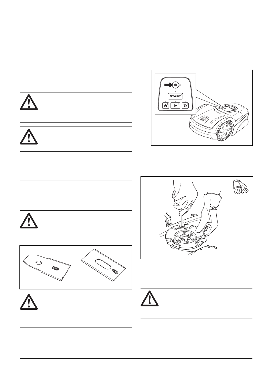
WARNING:
Husqvarna can only
guarantee safety if you use Husqvarna
original blades with the embossed crowned
H-mark logotype.
WARNING: You must replace the
screws when you replace the blades. The
used screws can wear quickly and make the
blade come loose, this can cause serious
injury.
Replace worn or damaged blades for a safe operation.
Replace the blades regularly for a satisfactory cut result
and a low energy use. All 3 blades and screws must
be replaced at the same time to get a balanced cutting
system.
6.4.1 To replace the blades
1. Push the STOP button.
2. Push the ON/OFF button for 3 seconds to set the
product to OFF. Make sure that the LED indicator
on the keypad goes out.
3. Put the product with the blade disc up on a soft
and clean surface.
4. Remove the 3 screws and blades for each cutting
disc.
5. Attach new blades and screws.
6. Make sure that the blades can pivot freely.
6.5 Battery
CAUTION:
Charge the battery fully
before you put the product into storage. If
the battery is not fully charged it can cause
damage to the battery.
If the operating time of the product is shorter than usual
between charges, this means that the battery is at the
end of its life cycle. Replace the battery to extend the
operating time.
1886 - 003 - 12.03.2026
Maintenance - 31

Note: The battery life is related to the length of
the season and how many hours a day the product
operates. A long season or many hours of operation
a day means that the battery must be replaced more
frequently.
6.6 Winter service
Take your product to your Husqvarna service for service
prior to winter storage. Regular winter service will
maintain the product in good condition and create
the best conditions for a new season without any
disruptions.
Service usually includes the following:
• Thorough cleaning of the body, the chassis, the
blade disc and all other moving parts.
• Testing of the product’s function and components.
• Checking and, if required, replacing wear items
such as blades and bearings.
• Testing the product’s battery capacity as well as a
recommendation to replace battery if necessary.
• If new firmware is available, the product is
updated.
32 - Maintenance 1886 - 003 - 12.03.2026
7 Troubleshooting
7.1 Introduction - troubleshooting
In this chapter you can find information and help about faults and symptoms of the product. You can find more
information and FAQ (Frequently Asked Questions) on www.husqvarna.com.
7.2 Fault messages
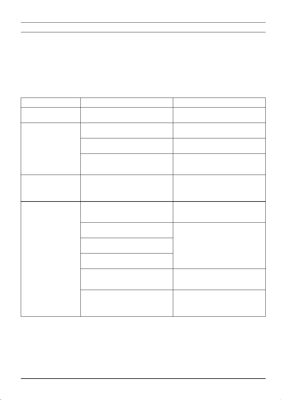
The fault messages in the table below are shown in the app. Speak to your Husqvarna service if the same message
shows frequently.
Message Cause Action
Wheel motor blocked, left/
right
Grass or other object around the drive
wheel.
Remove grass or other object.
Cutting system blocked
Grass or other object around the blade
disc.
Remove grass or other object.
The blade disc is in water. Move the product and prevent the collec-
tion of water in the work area.
The grass is too high. Cut the grass before you install the prod-
uct. Make sure that the grass is maximum
4 cm / 1.6 in.
Trapped
The product is behind a number of obsta-
cles in a small area.
Remove the obstacles or put the boundary
wire around the obstacle to make an is-
land. Refer to
To make an island on page
16
.
Outside working area
A section of boundary wire is put across
the other section of boundary wire to the
charging station.
Make sure that the boundary wire is con-
nected correctly.
The boundary wire is too near the edge of
the work area.
Make sure that the boundary wire is instal-
led correctly. Refer to
To install the boun-
dary wire on page 19
.
The work area slopes much by the boun-
dary loop.
The boundary wire is put in the incorrect
direction around an island.
Interference to the boundary wire from
metal objects such as fences, reinforce-
ment steel or buried cables nearby.
Move the boundary wire.
The product can not find the correct loop
signal because of interference with a loop
signal from a different product installation
nearby.
Put the product in the charging station and
generate a new loop signal.
1886 - 003 - 12.03.2026 Troubleshooting - 33
Message Cause Action
Empty battery
The product cannot find the charging sta-
tion.
Change the position of the guide wire. Re-
fer to
To install the guide wire on page 19
.
The battery is at the end of its life cycle. Replace the battery. Speak to your Husq-
varna service.
The antenna of the charging station is de-
fective.
Do a check if the indicator lamp in the
charging station flashes red. Refer to
Indi-
cator lamp in the charging station on page
38
.
The charging plates on the product or con-
tact plates on the charging station are de-
fective because of corrosion.
Clean the charging plates and contact
plates. Refer to
To clean the charging
plates and contact plates on page 31
. If
the problem stays speak to your Husqvar-
na service.
Wrong PIN code
An incorrect PIN code has been entered. 5
tries are permitted, and the product is then
blocked for a period of time.
Enter the correct PIN code. If you do
not know the correct PIN code, go to
www.husqvarna.com to get information
about how to get the PIN code or speak
to your Husqvarna service.
No drive
The product has got caught in something
and has been slipping.
Free the product and correct the cause of
problem. If it is because of wet grass, wait
until the lawn is dry before you use the
product.
The work area includes a steep slope. Steep slopes must be isolated. Refer to
To
examine where to put the boundary wire
on page 15
.
The guide wire is not put diagonally in the
slope.
Make sure that the guide wire is installed
diagonally across the slope. Refer to
To
put the boundary wire in a slope on page
16
.
Wheel motor overloaded,
left/right
Grass or other object around the drive
wheel.
Remove grass or object from the drive
wheel.
Collision sensor problem
The front wheels on the product are
blocked.
Free the product and correct the cause
of problem. If the problem stays speak to
your Husqvarna service.
Charging station blocked
The contact between the charging plates
on the product and the contact plates on
the charging station is not good. The prod-
uct has made a number of tries to charge.
Put the product in the charging station and
make sure that the charging plates and
contact plates are connected.
An object prevents the product to enter the
charging station.
Remove the object.
The charging station is tilted or bent. Put the baseplate on level ground.
The guide wire is not installed correctly. Install the guide wire correctly. Refer to
To
install the guide wire on page 19
.
There is dirt on the wheels that prevents
the product to enter the charging station.
Clean the product fully.
34 - Troubleshooting 1886 - 003 - 12.03.2026
Message Cause Action
Stuck in charging station
An object prevents the product to move
out from the charging station.
Remove the object.
There is dirt on the wheels that prevents
the product to enter the charging station.
Clean the product fully.
Upside down
The product is in an incorrect position, the
product is tilting too much or is upside
down.
Put the product in the correct position.
Lifted
The lift sensor has been enabled because
the product has been lifted.
Make sure that the product body can move
freely around its chassis. Remove or cre-
ate an island around objects that can
cause the chassis to be lifted. If the prob-
lem stays speak to your Husqvarna serv-
ice.
Wheel drive problem, right/
left
Grass or other object around the drive
wheel.
Clean the wheels and around the wheels.
Electronic problem
Temporary electronic or firmware related
problem in the product.
Restart the product. If the problem stays
speak to your Husqvarna service.
Loop sensor problem,
front/rear
Tilt sensor problem
Temporary problem
Invalid sub-device combi-
nation
Temporary battery prob-
lem
Safety function faulty
Charging system problem
Incorrect type of battery. Use original batteries recommended by
the manufacturer.
Battery problem
Temporary battery or firmware related
problem in the product.
Restart the product. If the problem stays
speak to your Husqvarna service.
Incorrect type of battery. Use original batteries recommended by
the manufacturer.
Temperature restriction
The temperature in the battery is too high
or too low to start operation.
The temperature in the battery is not in its
operating limits and charging/mowing has
stopped. Charging/mowing will start when
the temperature is restored to its limits.
Charging current too high
Incorrect or defective power supply unit. Restart the product. If the problem stays
speak to your Husqvarna service.
1886 - 003 - 12.03.2026 Troubleshooting - 35
Message Cause Action
No loop signal
The power supply or low-voltage cable are
not connected.
If the LED status indicator on the charging
station is not lit, it shows that there is no
power. Examine the power outlet connection
and the residual-current device. Make sure
that the low-voltage cable is connected to the
charging station.
The power supply or low-voltage cable are
damaged or not connected.
Replace the power supply or low-voltage ca-
ble.
The boundary wire is not connected to the
charging station.
Connect the boundary wire to the charging
station. Replace the connectors if damaged.
Refer to
To install the boundary wire on page
19
.
The boundary wire is damaged. Do a check of the LED status indicator on the
charging station. If it shows damage in the
boundary wire, replace the damaged section
with new boundary wire.
The product has tried to start but it is not in
the charging station and
ECO mode
is ena-
bled.
Put the product in the charging station and
start the product.
A section of the boundary wire is across the
other section of boundary wire to and from
an island.
Install the boundary wire in the correct direc-
tion around the island. Refer to
To install the
boundary wire on page 19
.
Problem with the pairing between the product
and the charging station.
Put the product in the charging station and
make a new loop signal. Refer to
New loop
signal on page 24
.
Interference from metal objects such as fen-
ces, reinforcement steel or buried cables
nearby.
Move the boundary wire and/or make islands
in the work area to increase the signal
strength.
The product is too far from the boundary
wire.
Install the boundary wire to make all parts of
the work area maximum 15 m / 50 ft. from
the boundary wire.
Mower tilted
The product is tilted more than the maximum
angle.
Move the product to a level area.
Invalid firmware con-
figuration
The firmware in the product is not updated. Put the product in the charging station and
update the firmware via FOTA. If the problem
stays speak to your Husqvarna service.
36 - Troubleshooting 1886 - 003 - 12.03.2026
7.3 Information and warning messages
The information messages in the table below are shown in the app. Speak to your Husqvarna service if the same
message shows frequently.
Message Cause Action
Settings restored
A
Reset all user settings
has been done. Usual operation of the product.
FlexiFence problem
The battery of the FlexiFence accessory
is low. The FlexiFence does not operate
when the battery is empty. The product
can cut in the stay-out zone if you start the
product before you charge the FlexiFence.
Park the product and charge the Flex-
iFence accessory before you start the
product.
The temperature in the FlexiFence acces-
sory is a higher than the maximum limit
and is set to off.
Put the product in an area with protec-
tion from the sun. Let the temperature of
the FlexiFence accessory decrease before
you start the product.
Guide not found
The guide wire is not connected to the
charging station.
Connect the guide wire to the charging
station. Refer to
To install the guide wire
on page 19
.
Damage in the guide wire. Replace the damaged section with new
guide wire.
The guide wire is not connected to the
boundary loop.
Connect the guide wire correctly to the
boundary loop. Refer to
To install the
guide wire on page 19
.
Loop signal created
New loop signal changed. Usual operation of the product.
Needs manual charging
The product is set to the
Secondary area
operating mode.
Put the product in the charging station.
Next start hh:mm
The schedule setting prevents the product
from operating.
Change the schedule settings. Refer to
Schedule on page 22
.
The product has operated the maximum
cutting time for the day.
Usual operation of the product.
Today's mowing comple-
ted
The product has operated the maximum
cutting time for the day.
Usual operation of the product. Refer to
Schedule on page 22
.
Connection NOT changed
The loop signal was not changed because
of an error.
Make a
New loop signal
a number of
times. Refer to
New loop signal on page
24
. If the problem stays speak to your
Husqvarna service.
1886 - 003 - 12.03.2026 Troubleshooting - 37
7.4 Indicator lamp in the charging station
The indicator lamp in the charging station must show a solid or flashing green light for a correct installation. If not,
follow the instructions in the troubleshooting table below.
Speak to your Husqvarna service for more information.
Light Cause Action
Green solid light Good signals. Usual operation of the product.
Green flashing light The signals are good and
ECO mode
is ena-
bled.
Usual operation of the product. Refer to
ECO
mode on page 22
.
Blue flashing light The boundary wire is not connected to the
charging station.
Make sure that the boundary wire is correctly
installed in the charging station. Refer to
To
install the boundary wire on page 19
.
Damage in the boundary wire. Find out where the damage is. Replace the
damaged section with new boundary wire.
Yellow flashing light The guide wire is not connected to the charg-
ing station.
Make sure that the guide wire is correctly
installed in the charging station. Refer to
To
install the guide wire on page 19
Damage in the guide wire. Find out where the damage is. Replace the
damaged section with new guide wire.
Red flashing light Interference in the antenna of the charging
station.
Speak to your Husqvarna service.
Red solid light Error in the circuit board or incorrect power
supply in the charging station. The error must
be corrected by your Husqvarna service
Speak to your Husqvarna service.
38 - Troubleshooting 1886 - 003 - 12.03.2026
7.5 Symptoms
If the product does not operate as usual, follow the symptoms table below. Speak to your Husqvarna service if you
cannot find the cause for the fault.
Symptoms Cause Action
The product has diffi-
culty docking.
The guide wire is not put straight in a line
and correct distance from the charging sta-
tion.
Do a check of the installation of the charging
station. Refer to
To install the charging sta-
tion on page 18
.
The guide wire is not put in the slot in the
charging station plate.
Make sure that the guide wire is put straight
in a line and put in the slot in the charging
station plate. Refer to
To install the guide
wire on page 19
.
The charging station is not on a level sur-
face.
Put the charging station on a level surface.
Refer to
To examine where to put the charg-
ing station on page 13
.
Dirt on the product prevents the product to
enter the charging station.
Clean the product fully. Refer to
Clean the
product on page 30
.
The charging plates on the product or con-
tact plates on the charging station are defec-
tive because of corrosion.
Clean the charging plates and contact plates.
Refer to
To clean the charging plates and
contact plates on page 31
.
The product operates
at the wrong time.
The start and stop times for operating are
incorrect.
Change the schedule settings. Refer to
Schedule on page 22
.
The time in the product is incorrect. Set the time in the
General
menu in the app.
The product vibrates. The cutting system is not in balance because
of damaged blades.
Examine the blades and screws and replace
them if necessary. Refer to
Replacement of
the blades on page 31
.
The cutting system is not in balance because
of too many blades in the same position.
Do a check that only one blade is attached to
each screw.
Different thickness of blades are installed on
the product.
Do a check if the blades are of different thick-
ness and replace if necessary.
The cutting disc is not installed correctly. Make sure that the screws for the cutting disc
are attached correctly.
The product oper-
ates, but the blade
disc does not rotate.
The product searches for the charging sta-
tion, or is moving to the starting point.
Usual operation for the product. The blade
disc does not rotate when the product is
searching for the charging station.
The product operates
for shorter periods
than usual between
charges.
Grass or other object causes a blockage to
the blade disc.
Remove and clean the blade disc. Refer to
To clean the chassis and blade disc on page
30
.
The battery is at the end of its life cycle. Replace the battery. Speak to your Husqvar-
na service.
Blunt blades. More energy is necessary
when cutting the grass.
Replace the blades. Refer to
Replacement of
the blades on page 31
.
Mowing and charg-
ing times are shorter
than usual.
The battery is at the end of its life cycle. Replace the battery. Speak to your Husqvar-
na service.
1886 - 003 - 12.03.2026 Troubleshooting - 39
Symptoms Cause Action
There is an error with
the installation of new
firmware via FOTA.
The firmware did not download correctly. Push a button on the display to start the firm-
ware installation again. If the problem stays
speak to your Husqvarna service.
The product is
parked for hours in
the charging station.
The product has operated the maximum cut-
ting time for the day.
Usual operation for the product. Refer to
Make an estimate of the necessary operating
time on page 22
.
The STOP button has been pushed. Enter the PIN code and push the Start but-
ton.
Parking mode is enabled. Change the operating mode. Refer to
Oper-
ating modes on page 25
.
The product does not operate if the battery
temperature is too high or too low.
Make sure that the charging station is put in
an area with protection from the sun.
Uneven mowing re-
sults.
The product operates for a small number of
hours per day.
Increase the cutting time. Refer to
Make an
estimate of the necessary operating time on
page 22
.
For the shape of the work area it is necessa-
ry to adjust the settings for
Lawn Coverage
to cover all parts of the work area.
Change the settings of the areas where the
product starts to cut and how often. Refer
to
Lawn Coverage and Systematic Passage
Mowing on page 23
.
The work area is too large. Decrease the size of the work area or extend
the schedule. Refer to
Make an estimate of
the necessary operating time on page 22
.
Blunt blades. Replace all the blades. Refer to
Replace-
ment of the blades on page 31
.
Long grass in relation to the set cutting
height.
Increase the cutting height and then lower it
when the grass is shorter.
Collection of grass by the blade disc or
around the motor shaft.
Remove the collection of grass and clean the
product. Refer to
Clean the product on page
30
.
The battery state
of charge is high,
but the product goes
back to the charging
station.
To prevent to become blocked in a small
area, the product follows the guide wire to
the charging station.
Usual operation for the product.
7.6 Find breaks in the loop wire
Breaks in the loop wire are usually the result of
unintentional physical damage to the wire such as when
gardening with a shovel. In countries with ground frost,
also sharp stones that move in the ground can damage
the wire. Breaks can also occur due to the wire being
stretched excessively during installation.
Mowing the grass too low right after the installation can
damage wire insulation. Damage to the insulation may
not cause disruptions until several weeks or months
later. To avoid this, always select the maximum cutting
height the first weeks after installation and then lower
the height one step at a time every second week until
the desired cutting height has been reached.
A damaged splicing of the loop wire can also lead to
disruptions several weeks after the splice was done.
A faulty splice can, for example, be the result of the
coupler not being pressed together hard enough with a
pair of pliers, or that a coupler of lower quality than the
original coupler has been used. Please first check all
known splices before further troubleshooting is done.
A wire break can be located by gradually halving the
distance of the loop where the break may have occurred
until there is only a very short section of the wire left.
The following method does not work if
ECO mode
is
activated. Make sure first that
ECO mode
is switched
off. Refer to
ECO mode on page 22
.
40 - Troubleshooting 1886 - 003 - 12.03.2026
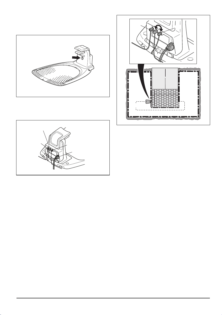
1. Check that the indicator lamp in the charging
station flashes blue, which indicates a break in
the boundary loop. Refer to
Indicator lamp in the
charging station on page 38
.
2. Check that the boundary wire connections to the
charging station are properly connected and not
damaged. Check that the indicator lamp in the
charging station is still flashing blue.
R
GUIDE
L
POWER
3. Switch the connections between the guide wire
and the boundary wire in the charging station.
Start by switching connection L and GUIDE.
If the indicator lamp has a solid green light, then
the break is somewhere on the boundary wire
between L and the point where the guide wire is
connected to the boundary wire (thick black line in
the illustration).
Guide
GUIDE
L
To rectify the fault you will need boundary wire,
connector(s) and coupler(s):
a) If the suspected boundary wire is short then it
is easiest to exchange all of the boundary wire
between L and the point where the guide wire is
connected to the boundary wire (thick black line).
b) If the suspected boundary wire is long (thick
black line) then do as follows: Put L and GUIDE
back to their original positions. Then disconnect
R. Connect a new loop wire to R. Connect the
other end of this new loop wire at the middle of the
suspected wire section.
1886 - 003 - 12.03.2026
Troubleshooting - 41
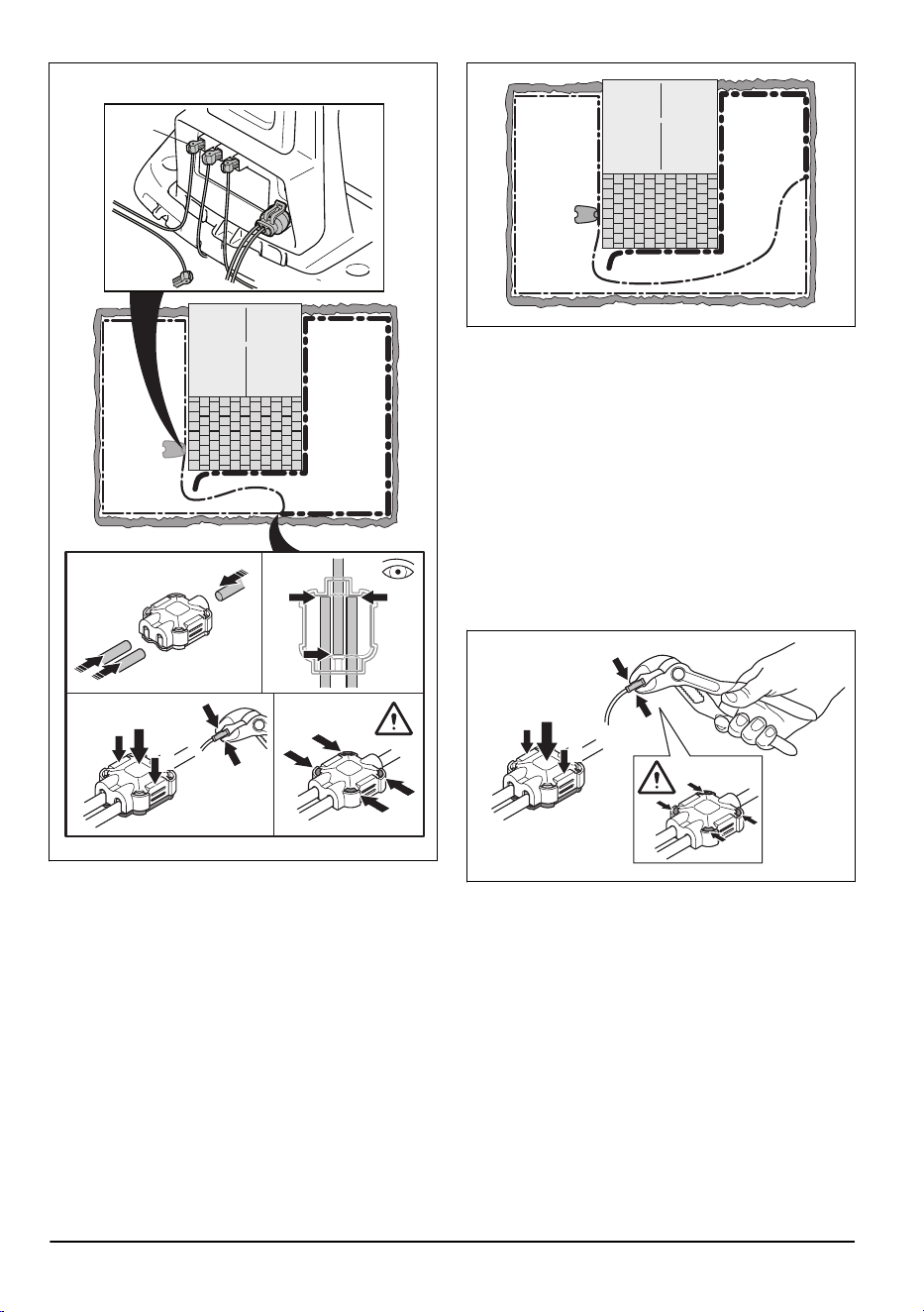
1
2
2
R
If the indicator lamp now is green, then the
break is somewhere in the wire between the
disconnected end to the point where the new wire
is connected (thick black line below). In that case,
move the connection for the new wire closer to
the disconnected end (roughly at the middle of
the suspected wire section) and check again if the
indicator lamp is green.
Continue until only a very short section of the wire
remains which is the difference between a solid
green light and a flashing blue light. Then follow
instruction in step 5 below.
4. If indicator lamp still flashes blue in step 3
above:Put L and GUIDE back in their original
positions. Then switch R and GUIDE. If indicator
lamp now is lit with a solid green light then
disconnect L and connect a new boundary wire to
L. Connect the other end of this new wire at the
middle of the suspected wire section. Follow the
same approach as in 3a) and 3b) above.
5. When the break is found, the damaged section
must be replaced with a new wire. Always use
original couplers.
1
2
2
42 - Troubleshooting 1886 - 003 - 12.03.2026
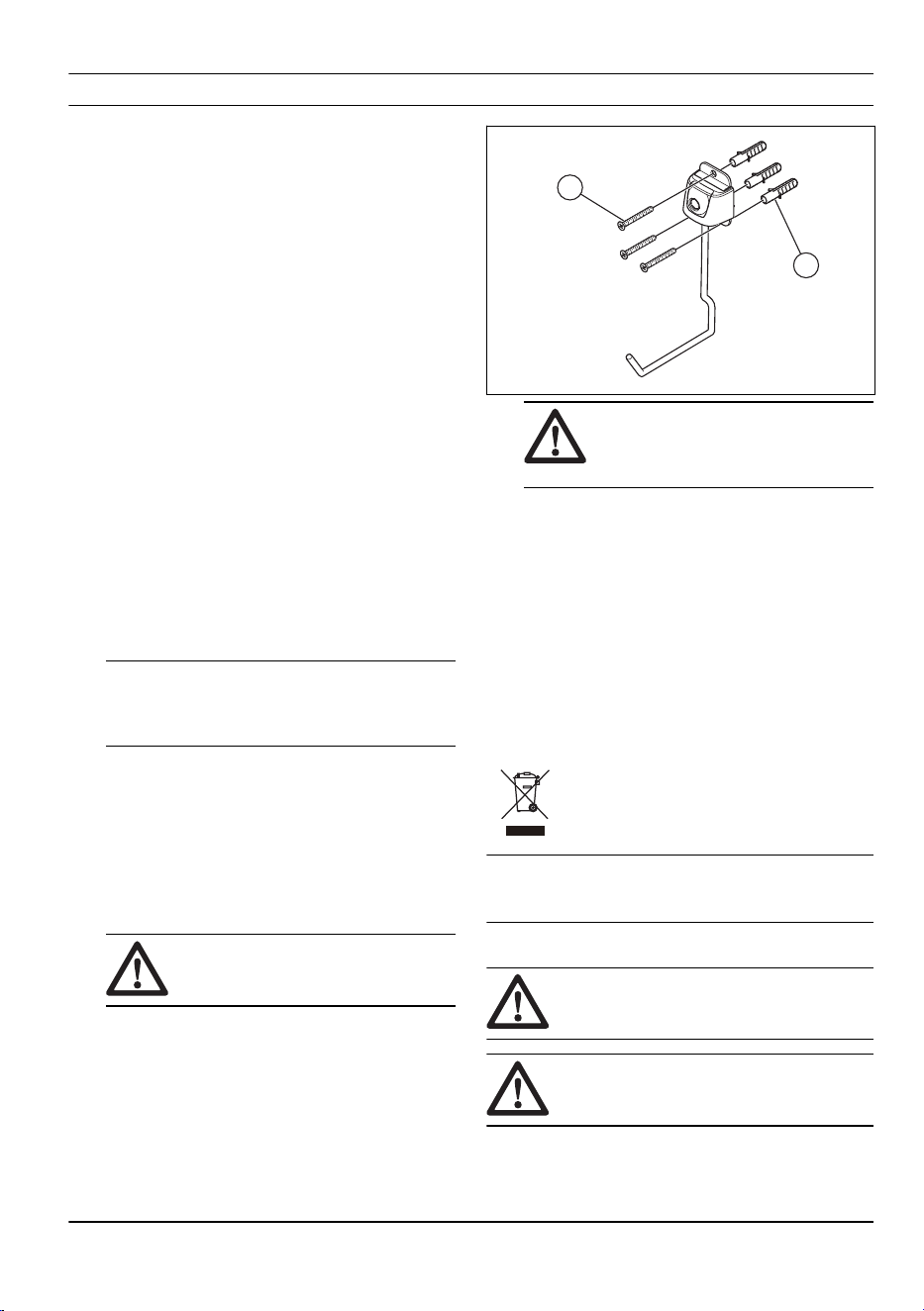
8 Transportation, storage and disposal
8.1 Transportation
The supplied Li-ion batteries obey the Dangerous Goods
Legislation requirements.
• Obey all applicable national regulations.
• Obey the special requirement on package and
labels for commercial transportations, including by
third parties and forwarding agents.
8.2 To put the product into storage
• Fully charge the product. Refer to
To charge the
battery on page 27
.
• Set the product to OFF. Refer to
To set the product
to OFF on page 27
.
• Clean the product. Refer to
Clean the product on
page 30
.
• Keep the product in a dry, frost free space.
• Keep the product with all wheels on level ground
or hang it on the wall with the storage hook. Refer
to
To install the storage hook on the wall on page
43
.
• If you keep the charging station indoors,
disconnect and remove the power supply and
all the connectors from the charging station. Put
the end of each connector wire in a connector
protection box.
Note: If you keep the charging station outdoors,
do not disconnect the power supply and the
connectors.
• Speak to your Husqvarna service for information
about available storage accessories for your
product.
8.2.1 To install the storage hook on the wall
• Install the storage hook indoors.
• Keep the storage hook out of sunlight.
• Install the storage hook on a drywall, wood or
concrete wall.
CAUTION: Make sure that the
wall can hold loads of minimum 30 kg.
• Remove the drill template from the carton of the
product to use it to install the storage hook on the
wall.
• Install the storage hook on the wall with the 3
screws (A). Use wall plugs (B) if it is necessary.
A
B
CAUTION:
Make sure that the
screws are applicable for your wall
type.
• Speak to your Husqvarna service agent for
information about available storage accessories for
your product.
8.3 Disposal
The symbol means that the product is not domestic
waste. Recycle it through your local collection system
for electrical and electronic equipment. This contributes
to proper end of life waste management. Contact
local authorities, domestic waste services, your dealer
or retailer for information. Incorrect disposal may
have potential negative effects on the environment
and human health, due to the potential presence of
hazardous substances.
Note:
The symbol shows on the product or package of
the product.
8.3.1 To remove the battery
WARNING: Use protective gloves.
CAUTION: Do not touch the circuit
boards.
1. Push the ON/OFF button for 3 seconds to switch
off the product.
1886 - 003 - 12.03.2026
Transportation, storage
and disposal - 43
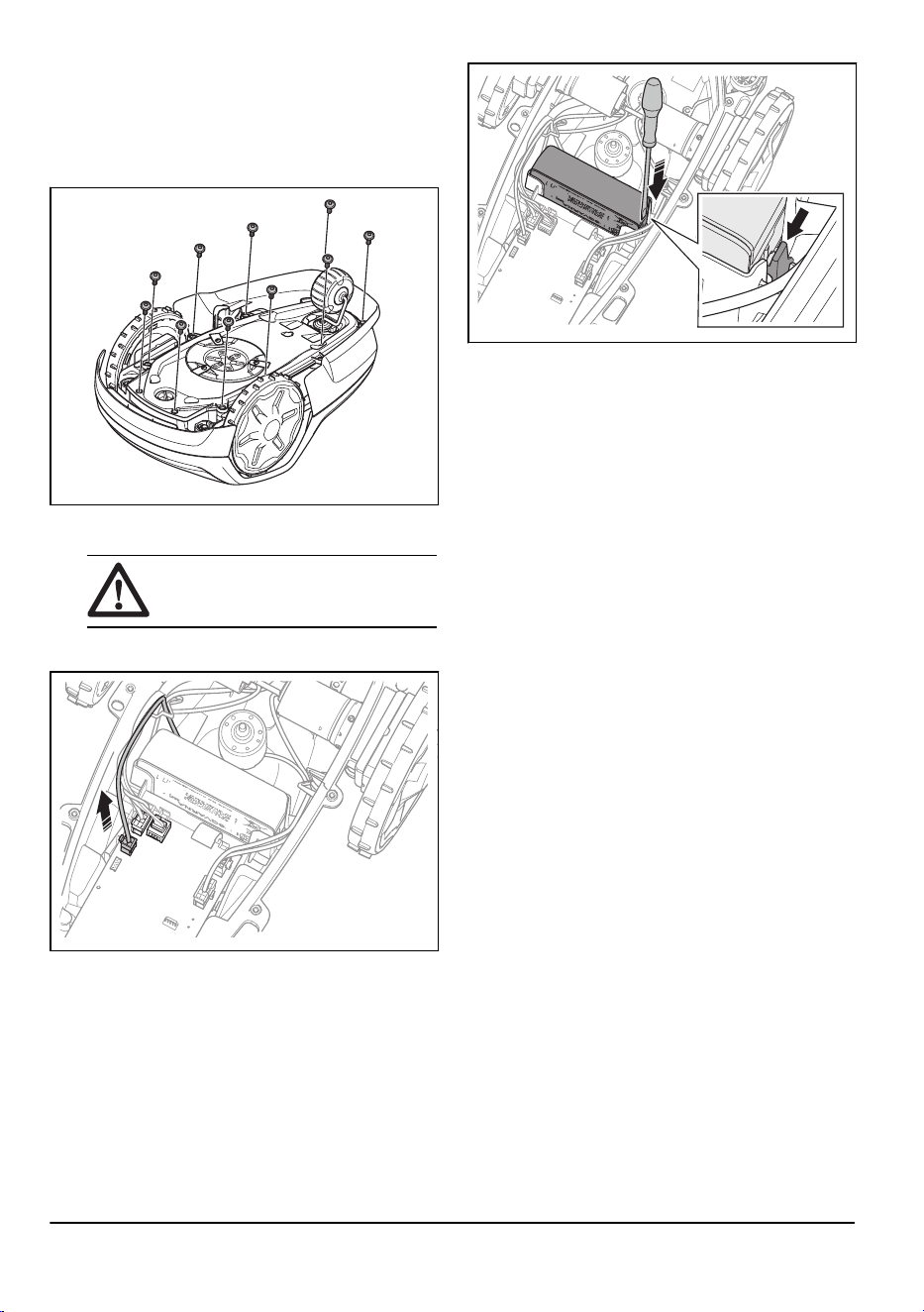
2. Make sure that the product is disabled. The
indicator lamp on the ON/OFF button is not
on when the product is disabled. Refer to
LED
indicator on the keypad on page 10
.
3. Put the product with the blade disc up.
4. Remove the 10 screws with a Torx 20.
5. Carefully lift the lower section of the chassis and
put it adjacent to the upper chassis.
CAUTION: Be careful, the cable is
connected to the main board.
6. Disconnect the battery cable from the main circuit
board.
7. Use a screwdriver to push the clips on each side of
the battery to remove it.
44
- Transportation, storage and
disposal
1886 - 003 - 12.03.2026
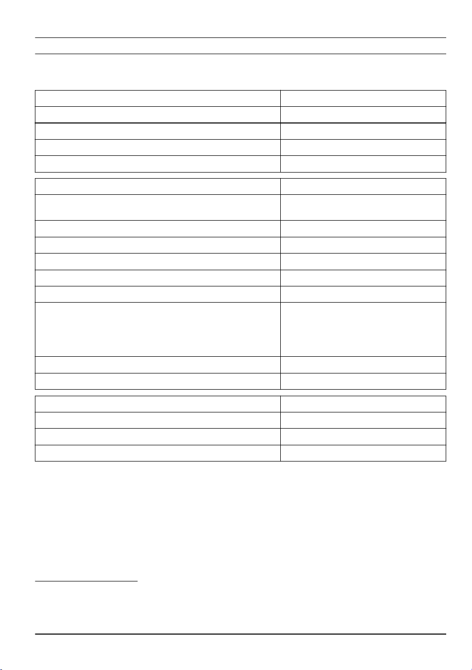
9 Technical data
9.1 Technical data
Dimensions Automower
®
Aspire
™
R4
Length, cm / in. 55 / 21.7
Width, cm / in. 33 / 13.0
Height, cm / in. 22 / 8.7
Weight, kg / lb 5.9 / 13.0
Electrical system Automower
®
Aspire
™
R4
Battery, Lithium-Ion 18 V/2.0 Ah Art.No 590 21 42-04, 590 21 42-10, 590 21 42-11,
590 21 42-12
Battery, Lithium-Ion 18.5 V/2.0 Ah Art.No 590 21 42-07, 590 21 42-08, 590 21 42-09
Power supply (28V DC), V AC 100-240
Low-voltage cable length, m / ft. 5 / 16.4
Mean energy consumption at maximum use 3 kWh/month in a 400m
2
work area
Charge current, A DC 1 / 1.3
Type of Power Supply Unit
10
ADP-28AW XX, ADP-28AR
XX, ADP-40KR XX, ADP-40FW
XX, FW7313/28/D/XX/Y/1.0/PI,
FW7313/28/D/XX/Y/1.3,
FW7313/28/D/XX/Y/1.3/PI
Average mowing time, min 70
Average charging time, min 75 / 60
Boundary wire antenna Automower
®
Aspire
™
R4
Operating Frequency Band, Hz 100-80000
Maximum magnetic field
11
, dBuA/m 82
Maximum Radio-frequency power
12
, mW @60m <25
10
XX, YY can be any alphanumeric characters or blank for marketing purpose only, no technical differences.
The "XX" specifies the country version, such as JP, and the "Y" specifies the product revision, such as V.
11
Measured according to EN 303 447.
12
Maximum active output power to antennas in the frequency band in which the radio equipment operates.
1886 - 003 - 12.03.2026 Technical data - 45
Sound data
13
Automower
®
Aspire
™
R4
Sound level, perceived, dB (A) 59
Measured sound power noise level, dB (A) 58
Noise emissions uncertainties K
WA
, dB (A) 2
Sound pressure noise level at the operator’s ear
14
, dB (A) 50
Mowing Automower
®
Aspire
™
R4
Area capacity m² / acre +/- 20% 400 / 0.1
Cutting system 3 pivoted cutting blades
Cutting motor speed, rpm 2670
Power consumption during cutting, W +/- 20 % 20
Cutting height, cm / in. 2-4.5 / 0.8-1.8
Cutting width, cm / in. 16 / 6.3
Narrowest possible passage, cm / in. 60 / 24
Maximum slope for cutting area, % 25
Maximum slope for boundary wire, % 10
Maximum length boundary wire, m / ft. 300 / 980
Maximum length guide loop
15
, m / ft. 150 / 490
IP-code Automower
®
Aspire
™
R4
Product IPX5
Charging station IPX5
Power supply IPX4/IP44
Bluetooth
®
Automower
®
Aspire
™
R4
Operating frequency band, MHz 2402-2480
Maximum transmitted power, dBm 9
Wi-Fi Automower
®
Aspire
™
R4
Frequency band support
16
Channel 1-11 (2412-2462 MHz)
Channel 12-13 (2467-2484 MHz)
Channel 14
Operating frequency band, MHz 2402-2480
Maximum transmitted power, dBm 20
13
Determined according to Directive 2006/42/EC and standard EN 50636-2-107. Except Sound level, perceived
that is measured according to ISO 11094:1991.
14
Sound pressure noise uncertainties K
pA
, 2-4 dB (A)
15
The guide loop is the loop that if formed by the guide wire and the part of the boundary wire from the junction
with the guide wire to the right connection in the charging station.
16
Channel 12-14 only used in countries where it is available.
46 - Technical data 1886 - 003 - 12.03.2026

Husqvarna AB does not guarantee full compatibility between the product and other types of wireless systems such as
remote controls, radio transmitters, hearing loops, underground electric animal fencing or similar.
The products are made in England or the Czech Republic. Refer to information on the rating plate. Refer to
Introduction on page 7
.
9.2 Registered trademarks
The
Bluetooth
®
word mark and logos are registered trademarks owned by
Bluetooth SIG, inc.
and any use of such
marks by Husqvarna is under license.
The Wi-Fi CERTIFIED
™
logo is a registered trademark of Wi-Fi Alliance
®
. This product is Wi-Fi Alliance
®
certified.
1886 - 003 - 12.03.2026 Technical data - 47

www.husqvarna.com
Original instructions
1147118-26
2026-03-24