1
H
U
N
T
E
R
.
US
E
R
MAN
U
AL
H
U
N
T
E
R
.
US
E
R
MAN
U
AL
D
o
c
um
e
nt
v
e
rs
i
on
S
afe
ty
I
n
f
orm
a
t
i
on
A
tt
e
nt
i
on
CON
T
EN
TS
H
U
N
T
E
R
.
I
ntro
d
u
c
t
i
on
.
C
ompon
e
nt
li
st
.
T
ech
sp
eci
fi
ca
t
i
ons
.
R
e
qu
i
r
e
m
e
nt
f
or
de
v
el
opm
e
nt
T
he
B
a
s
ic
s
.
S
t
a
tus
i
n
dica
t
i
on
.
I
nstru
c
t
i
ons
on
elec
tr
ical
i
nt
e
r
face
s
..
T
op
elec
tr
ical
i
nt
e
r
face
..
R
ea
r
elec
tr
ical
i
nt
e
r
face
.
R
e
mot
e
c
ontro
l
i
nstru
c
t
i
ons
.
I
nstru
c
t
i
ons
on
c
ontro
l
de
m
a
n
d
s
a
n
d
mov
e
m
e
nts
G
e
tt
i
n
g
S
t
a
rt
ed
.
U
s
e
a
n
d
op
e
r
a
t
i
on
.
C
ha
r
gi
n
g
a
n
d
ba
tt
e
ry
r
e
p
lace
m
e
nt
.
D
e
v
el
opm
e
nt
..
CAN
m
e
ss
age
proto
c
o
l
..
CAN
cable
c
onn
ec
t
i
on
..
I
mp
le
m
e
nt
a
t
i
on
o
f
CAN
c
omm
a
n
d
c
ontro
l
.
F
i
rmw
a
r
e
up
g
r
ade
s
.
H
U
N
T
E
R
.
R
O
S
P
ackage
Q
&
A
P
ro
d
u
c
t
D
i
m
e
ns
i
ons
.
I
ll
ustr
a
t
i
on
diag
r
a
m
o
f
pro
d
u
c
t
e
xt
e
rn
al
di
m
e
ns
i
ons
3
1 V.2.0.0 2023/03/12
吴
忠
义
Document
creation,
image
update
2 V.2.0.1 2023/04/19
吴
忠
义
Sync GitHub
commands
3 V.2.0.2 2023/08/21
吴
忠
义
1. Delete DB9
(RS232)
related
content
2. Update the
firmware
upgrade
tutorial
3. Pictures
and
instructions of
the remote
control
4. Increase
the
precautions
when charging
4 V2.0.3 2023/09/07
何
⼠
⽟
Optimize
layout
4
This chapter contains important safety information, before the robot is powered on for he
fi
rst
time, any individual or organization must read and understand this information before using the
device. If you have any questions about use, please contact us at support@agilex.ai. Please
follow and implement all assembly instructions and guidelines in the chapters of this manual,
which is very important. Particular attention should be paid to the text related to the warning
signs.
The information in this manual does not include the design, installation and operation of a
complete robot application, nor does it include all peripheral equipment that may a
ff
ect the
safety of the complete system. The design and use of the complete system need to comply with
the safety requirements established in the standards and regulations of the country where the
robot is installed. HUNTER 2.0 integrators and end customers have the responsibility to ensure
compliance with the applicable laws and regulations of relevant countries, and to ensure that
there are no major dangers in the complete robot application. This includes but is not limited to
the following:
Safety Information
5 V2.0.4 2023/09/08
吴
忠
义
1.Synchroniza
tion
parameter
list
2.Robot
charging
diagram
3.Updated
product
dimensions
description
diagram
5
E
ff
ectiveness and responsibility
Make a risk assessment of the complete robot system.
Connect the additional safety equipment of other machinery de
fi
ned by the risk assessment
together.
Con
fi
rm that the design and installation of the entire robot system's peripheral equipment,
including software and hardware systems, are correct.
This robot does not have a complete autonomous mobile robot, including but not limited to
automatic anti-collision, anti-falling, biological approach warning and other related safety
functions. Related functions require integrators and end customers to follow relevant
regulations and feasible laws and regulations for safety assessment , To ensure that the
developed robot does not have any major hazards and safety hazards in actual applications.
Collect all the documents in the technical
fi
le: including risk assessment and this manual.
Environmental Considerations
For the
fi
rst-time use,please read this manual carefully to understand the basic operating
content and operating speci
fi
ca-tion.
No passengers.
For remote control operation, select a relatively open area to use HUNTER 2.0, because
HUNTER 2.0 is not equipped with any automatic obstacle avoidance sensor. Please keep a
safe distance of more than 2 meters when operating HUNTER 2.0.
Use HUNTER 2.0 always between -10
℃
~45
℃
ambient temperature.
If HUNTER 2.0 is not con
fi
gured with separate custom IP protection, its water and dust
protection will be IP22 ONLY.
Pre-work Checklist
Make sure each device has su
ffi
cient power.
Make sure HUNTER 2.0 does not have any obvious defects.
Check if the remote controller battery has su
ffi
cient power.
When using, make sure the emergency stop switch has been released.
Operation
●
●
●
●
●
●
●
●
●
●
●
●
●
●
6
In remote control operation, make sure the area around is relatively spacious.
Make sure to operate the Hunter 2.0 within the visual range. The maximum load of HUNTER
2.0 is 150KG. When in use, ensure that the payload does not exceed 150KG.
When installing an external extension on HUNTER 2.0, con
fi
rm the position of the center of
mass of the extension and make sure it is at the center of rotation.
Please charge in time when the device is low battery alarm. When HUNTER 2.0 has a defect,
please immediately stop using it to avoid secondary damage.
When HUNTER 2.0 has had a defect, please contact the relevant technical to deal with it, do
not handle the defect by yourself.
Always use HUNTER 2.0 in the environment with the protection level requires for the
equipment.
It is forbidden to push the chassis in the parking status, and the parking can be manually
released in an emergency status.
When charging, make sure the temperature is above 0
℃
.
Maintenance
Regularly check the pressure of the tire, and keep the tire pressure is maintained at 0.8bar.
If the tire is severely worn or burst, please replace it in time.
If the battery plan not to use for a long time, it need to be charged periodically in every 2 to
3 months.
This section includes some precautions that should be paid attention to for HUNTER 2.0 use and
development.
Battery
The battery supplied with HUNTER 2.0 is not fully charged in the factory setting, but its
speci
fi
c power capacity can be displayed on the voltmeter at real end of HUNTER 2.0
chassis or read via CAN bus communication interface. The battery recharging can be
stopped when the green LED on the charger turns green. Note that if you keep the charger
●
●
●
●
●
●
●
●
●
●
●
Attention
●
7
connected after the green LED gets on, the charger will continue to charge the battery with
about 0.1A current for about 30 minutes more to get the battery fully charged;
Please do not charge the battery after its power has been depleted, and please charge the
battery in time when low battery level alarm is on;
Static storage conditions: The best temperature for battery storage is -10
℃
to 45
℃
; in case
of storage for no use, the battery must be recharged and discharged once about every 2
months, and then stored in full voltage state. Please do not put the battery in
fi
re or heat up
the battery, and please do not store the battery in high-temperature environment;
Charging: The battery must be charged with a dedicated lithium battery charger; lithium-ion
batteries cannot be charged below 0°C (32°F) and modifying or replacing the original
batteries are strictly prohibited.
HUNTER 2.0 only supports the replacement and use of the battery provided by us, and the
battery can be charged separately.
Notes while charging
When charging, do not cover the charger with anything, and do not block the air inlet and outlet.
The charger should be placed in a place out of reach of children.
When charging, the charger and battery should be used in an indoor environment with good
ventilation and heat dissipation. It is strictly prohibited to use it in an environment with humidity,
high temperature, or flammable and explosive gases.
Please do not carry the charger with you while driving to avoid vibration damage.
There is high voltage inside the casing. Non-professionals are not allowed to disassemble it.
Please read the instructions carefully before use. The manufacturer is not responsible for any
damage caused by failure to operate in the correct manner.
Operational environment
The operating temperature of HUNTER 2.0 is -10
℃
to 45
℃
; Please do not use it below -10
℃
and above 45
℃
;
The requirements for relative humidity in the use environment of HUNTER 2.0 are: maximum
80%, minimum 30%;
Please do not use it in the environment with corrosive and
fl
ammable gases or closed to
combustible substances;
Do not place it near heaters or heating elements such as large coiled resistors, etc.;
●
●
●
●
●
●
●
●
●
●
●
●
●
●
8
Except for specially customized version (IP protection class customized), HUNTER 2.0 is not
water-proof, thus please do not use it in rainy, snowy or water-accumulated environment;
The elevation of recommended use environment should not exceed 1,000m;
The temperature di
ff
erence between day and night of recommended use environment should
not exceed 25
℃
;
Electrical/extension cords
For the extended power supply on top, the current should not exceed 10A and the total
power should not exceed 240W;
For the extended power supply of top and tail, each ports must not be greater than 24V10A,
the total output current must not be greater than 15A, total power should not exceed 360W.
When the system detects that the battery voltage is lower than the safe voltage class,
external power supply extensions will be actively switched to. Therefore, users are suggested
to notice if external extensions involve the storage of important data and have no power-o
ff
protection.
Other notes
When handling and setting up, please do not fall o
ff
or place the chassis upside down;
For non-professionals, please do not disassemble the chassis without permission.
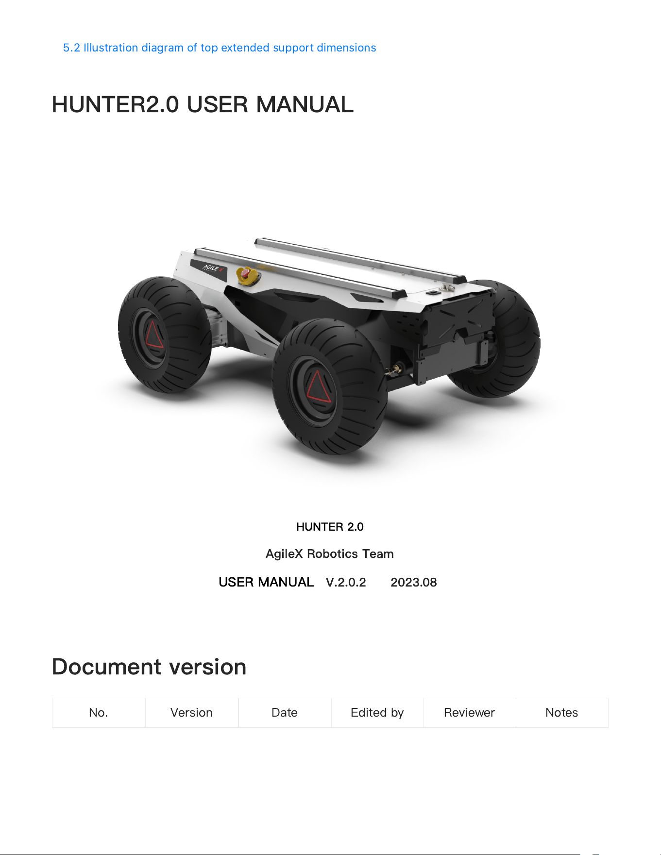
HUNTER 2.0 is designed as a programmable UGV( UNMANNED GROUND CHASSIS) upon
Ackermann model, of which the chassis is based on Ackermann steering. Therefore, it has similar
characteristics to cars but has more signi
fi
cant advantages on Portland cement and asphalt
roads over them. Compared to the four-wheel di
ff
erential chassis, HUNTER 2.0 chassis has a
higher load carrying capacity and can reach higher movement speed with less wear of structure
and tires for long-term operation. Although HUNTER 2.0 is not designed as suitable for all kinds
of terrains, it is equipped with a rocker arm suspension which can pass common obstacles such
as speed bumps, etc. Additional components such as stereo camera, laser radar, GPS, IMU and
robotic manipulator can be optionally installed on HUNTER 2.0 for advanced navigation and
●
●
●
●
●
●
●
●
CONTENTS
1 HUNTER 2.0 Introduction
9
computer vision applications. HUNTER 2.0 is frequently used for autonomous driving education
and research, indoor and outdoor security patrolling, environment sensing, general logistics and
transportation.
1.1 Component list
1.2 Tech speci
fi
cations
Name
Quantity
HUNTER 2.0 Robot body
x1
Battery charger(AC 220V)
x1
Aviation plug(male, 4-pin)
x1
Remote control transmitter(optional)
x1
USB to CAN communication module
x1
Parameter Types
Items
Values
Mechanical specifications
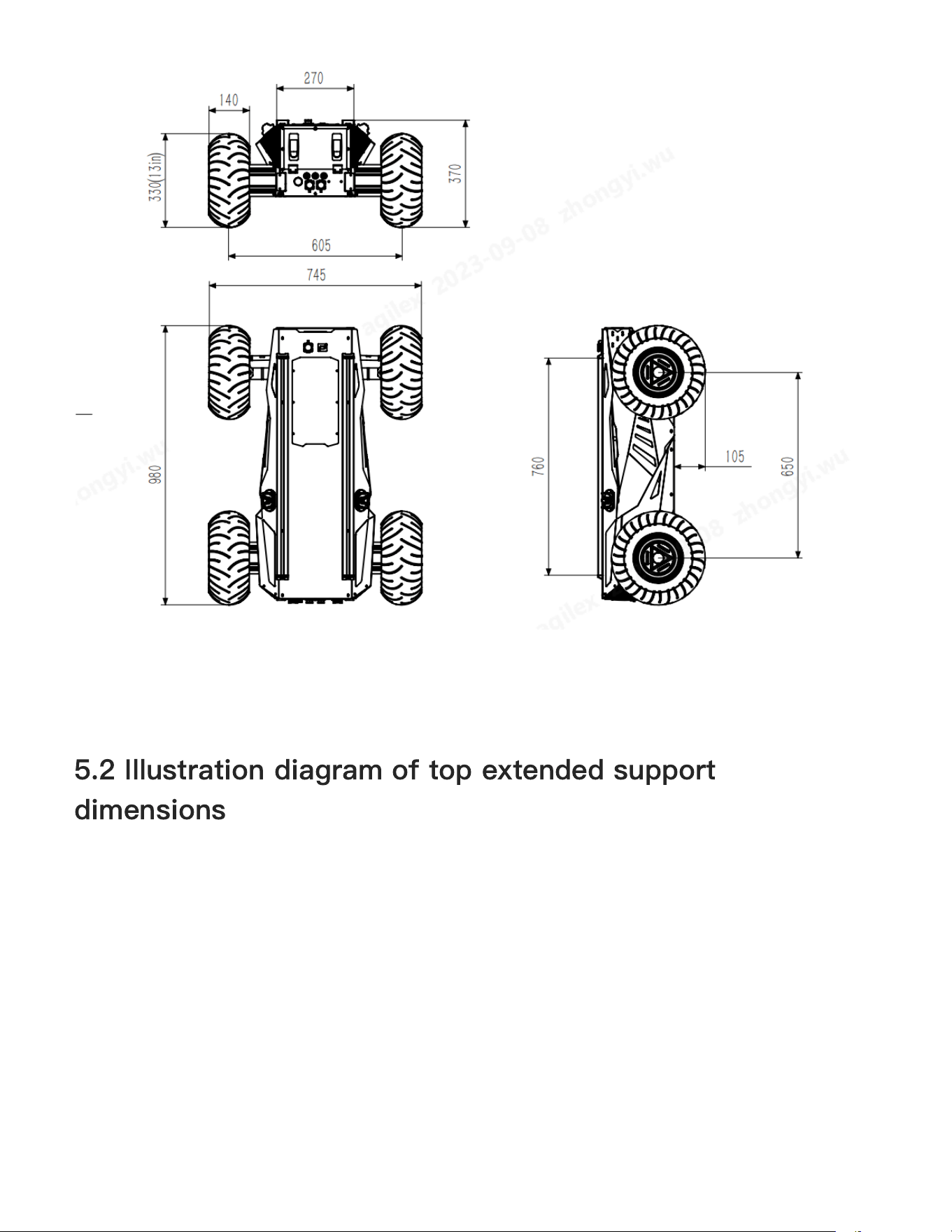
L × W × H (mm)
980 × 745 × 370
Wheelbase (mm)
650
Front/rear wheel base (mm)
605
Weight of chassis body (kg)
65/70
Battery Type Lithium battery
Battery parameters
24V 30Ah/60Ah
Power drive motor
DC brushless 2 ×400W
Steering drive motor
DC brushless 400W
Parking mode
Power off electromagnetic band
type brake
Steering
Front wheel Ackermann
10
FS RC transmitter is provided (optional) in the factory setting pf HUNTER 2.0, which allows users
to control the chassis of robot to move and turn; CAN interfaces on HUNTER 2.0 can be used for
1.3 Requirement for development
Suspension form Front wheel non-independent
suspension
Steering motor reduction
ratio
-
Steering motor encoder -
Drive motor reduction ratio 1
:
40
Drive motor sensor Magnetic braiding 2500
Performance parameters
IP Grade
IP22
Maximum speed (km/h)
1.5
Minimum turning radius (m)
1.6
Maximum gradeability (°)
10°
Ground clearance (mm)
100mm
Maximum battery life (h)
8
Maximum distance (km)
20KM (24V30Ah
battery
)
40KM (24V60Ah
battery
)
Charging time (h)
3h (24V30Ah
battery
)
6h (24V60Ah
battery
)
Working temperature (
℃
)
-10~40
Control
Control mode
Remote control Control
Command control mode
RC transmitter
2.4G/extreme distance 200M
System interface
CAN
11
user
’
s customization.
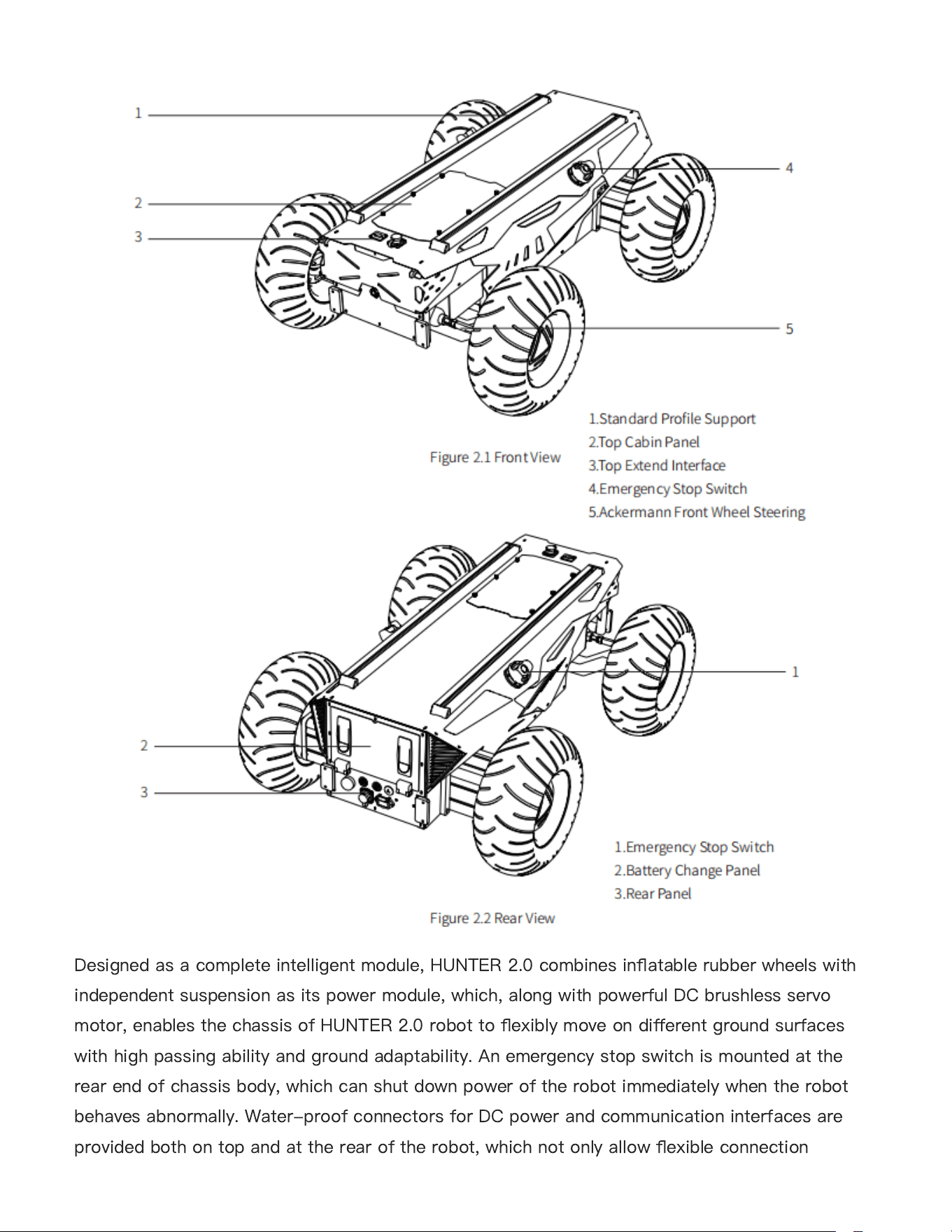
The section provides a brief introduction to the HUNTER 2.0 mobile robot platform, as shown in
Figure 2.1 and 2.2
2 The Basics
12
Designed as a complete intelligent module, HUNTER 2.0 combines in
fl
atable rubber wheels with
independent suspension as its power module, which, along with powerful DC brushless servo
motor, enables the chassis of HUNTER 2.0 robot to
fl
exibly move on di
ff
erent ground surfaces
with high passing ability and ground adaptability. An emergency stop switch is mounted at the
rear end of chassis body, which can shut down power of the robot immediately when the robot
behaves abnormally. Water-proof connectors for DC power and communication interfaces are
provided both on top and at the rear of the robot, which not only allow
fl
exible connection
13
between the robot and external components but also ensures necessary protection to the internal
of the robot even under severe operating conditions.
Users can identify the status of chassis body through the voltmeter, the beeper and lights
mounted on HUNTER 2.0. For details, please refer to Table 2.1.
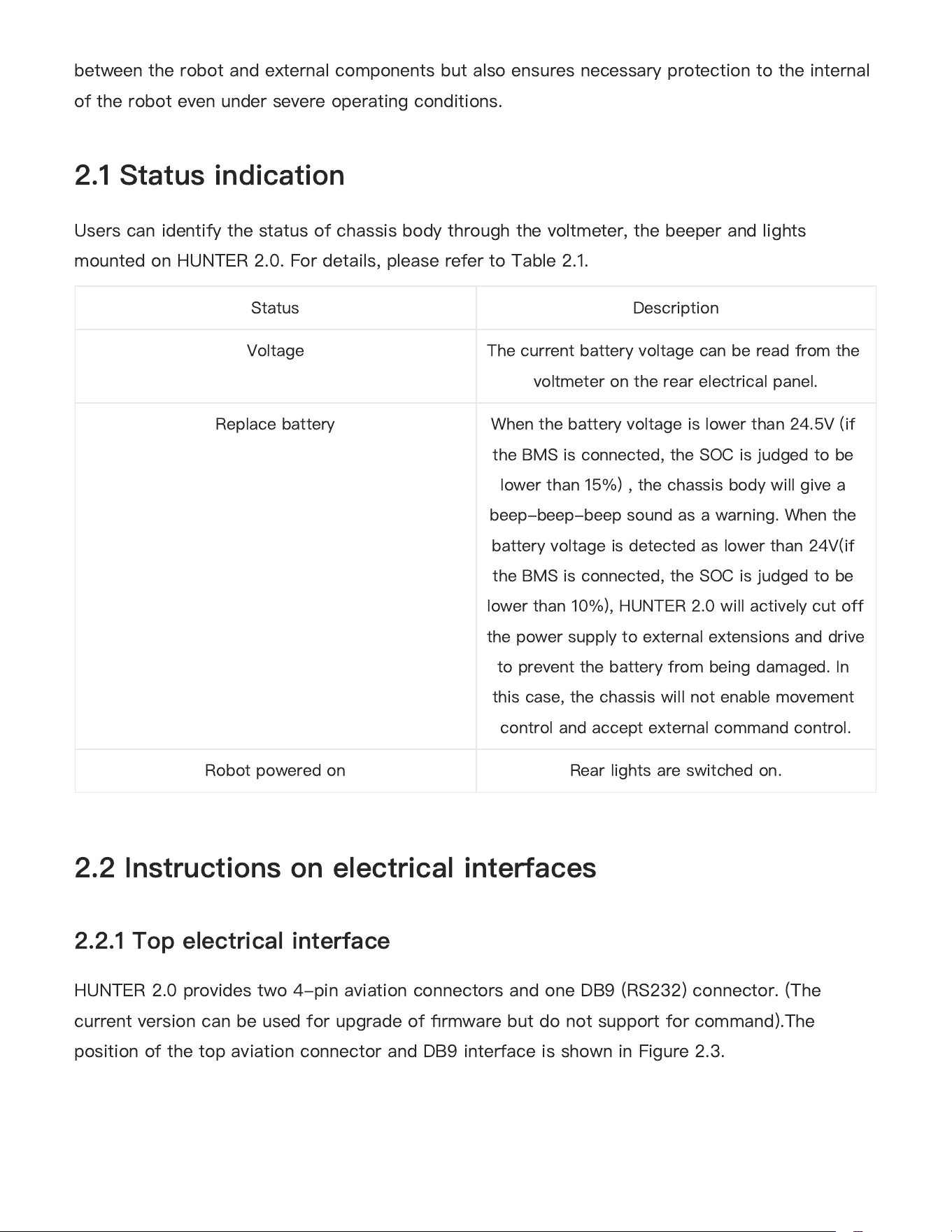
HUNTER 2.0 provides two 4-pin aviation connectors and one DB9 (RS232) connector. (The
current version can be used for upgrade of
fi
rmware but do not support for command).The
position of the top aviation connector and DB9 interface is shown in Figure 2.3.
2.1 Status indication
2.2 Instructions on electrical interfaces
2.2.1 Top electrical interface
Status
Description
Voltage
The current battery voltage can be read from the
voltmeter on the rear electrical panel.
Replace battery
When the battery voltage is lower than 24.5V (if
the BMS is connected, the SOC is judged to be
lower than 15%) , the chassis body will give a
beep-beep-beep sound as a warning. When the
battery voltage is detected as lower than 24V(if
the BMS is connected, the SOC is judged to be
lower than 10%), HUNTER 2.0 will actively cut off
the power supply to external extensions and drive
to prevent the battery from being damaged. In
this case, the chassis will not enable movement
control and accept external command control.
Robot powered on
Rear lights are switched on.
14
Figure 2.3 Schematic Diagram of HUNTER 2.0 Electrical Interface on Top
HUNTER 2.0 has each aviation extension interface respectively on top and at rear end which is
con
fi
gured with a set of power supply and a set of CAN communication interface. These
interfaces can be used to supply power to extended devices and establish communication. The
speci
fi
c de
fi
nitions of pins are shown in Figure 2.4.
It should be noted that, the extended power supply here is internally controlled, which means the
power supply will be actively cut o
ff
once the battery voltage drops below the pre-speci
fi
ed
threshold voltage. Therefore, users need to notice that HUNTER 2.0 platform will send a low
voltage alarm before the threshold voltage is reached and also pay attention to battery
recharging during use.
Figure 2.4 Description of Top Aviation Interface Pins
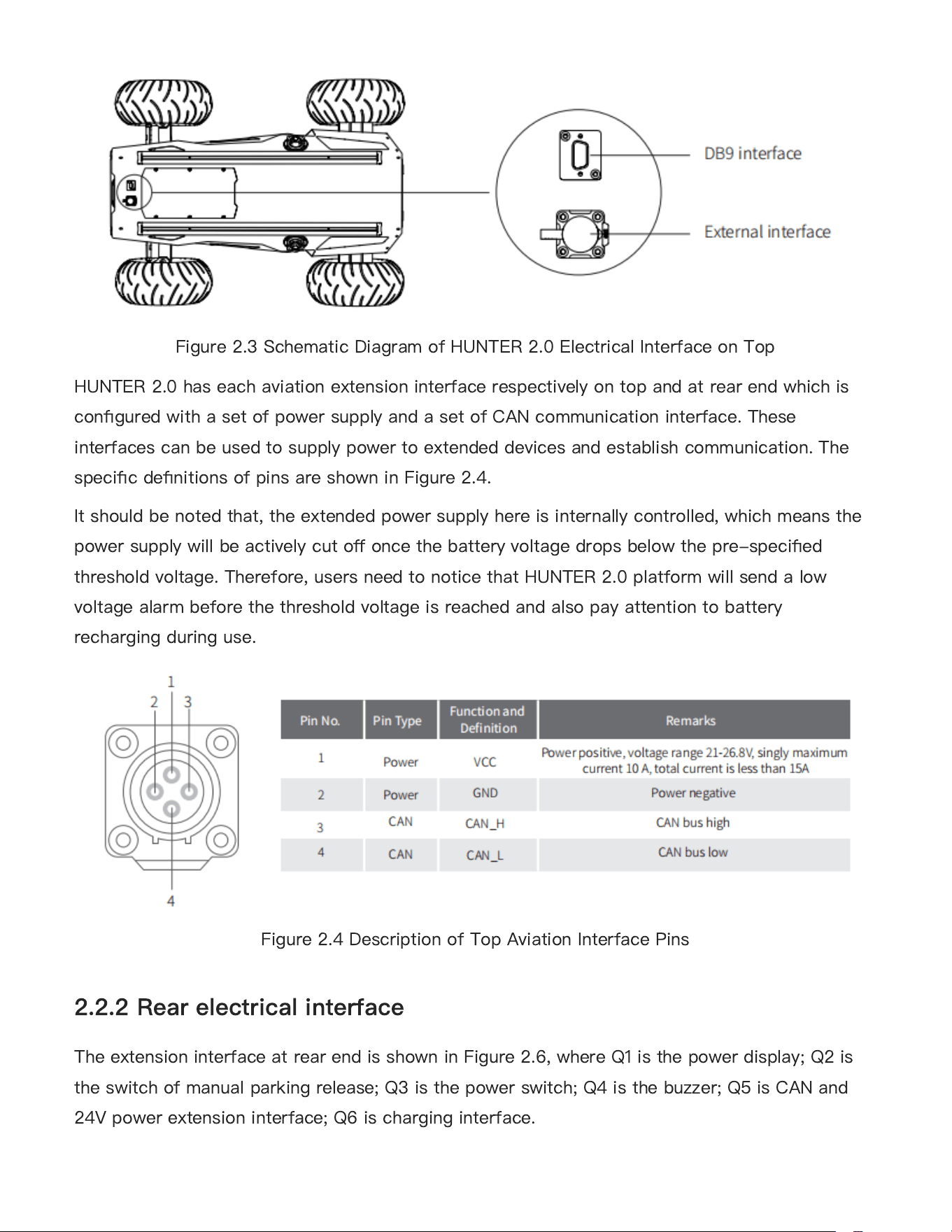
The extension interface at rear end is shown in Figure 2.6, where Q1 is the power display; Q2 is
the switch of manual parking release; Q3 is the power switch; Q4 is the buzzer; Q5 is CAN and
24V power extension interface; Q6 is charging interface.
2.2.2 Rear electrical interface
15
Figure 2.6 Rear View
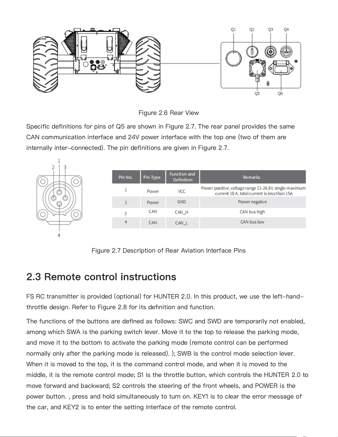
Specific definitions for pins of Q5 are shown in Figure 2.7. The rear panel provides the same
CAN communication interface and 24V power interface with the top one (two of them are
internally inter-connected). The pin definitions are given in Figure 2.7.
Figure 2.7 Description of Rear Aviation Interface Pins
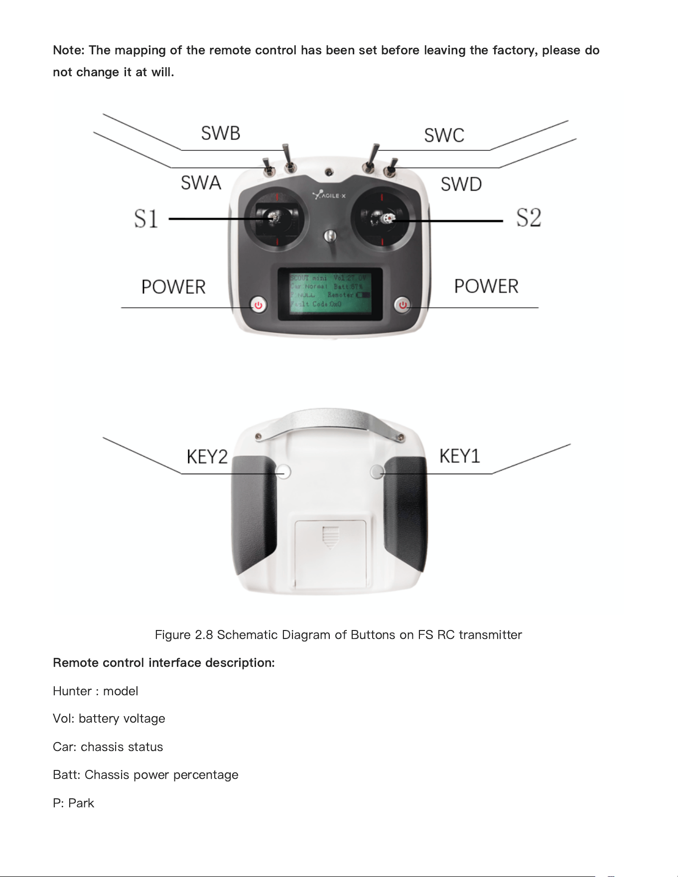
FS RC transmitter is provided (optional) for HUNTER 2.0. In this product, we use the left-hand-
throttle design. Refer to Figure 2.8 for its de
fi
nition and function.
The functions of the buttons are defined as follows: SWC and SWD are temporarily not enabled,
among which SWA is the parking switch lever. Move it to the top to release the parking mode,
and move it to the bottom to activate the parking mode (remote control can be performed
normally only after the parking mode is released). ); SWB is the control mode selection lever.
When it is moved to the top, it is the command control mode, and when it is moved to the
middle, it is the remote control mode; S1 is the throttle button, which controls the HUNTER 2.0 to
move forward and backward; S2 controls the steering of the front wheels, and POWER is the
power button. , press and hold simultaneously to turn on. KEY1 is to clear the error message of
the car, and KEY2 is to enter the setting interface of the remote control.
2.3 Remote control instructions
16
Note: The mapping of the remote control has been set before leaving the factory, please do
not change it at will.
Figure 2.8 Schematic Diagram of Buttons on FS RC transmitter
Remote control interface description:
Hunter : model
Vol: battery voltage
Car: chassis status
Batt: Chassis power percentage
P: Park
17
Remoter: remote control battery level
Fault Code: Error information (Represents byte [5] in 211 frame)
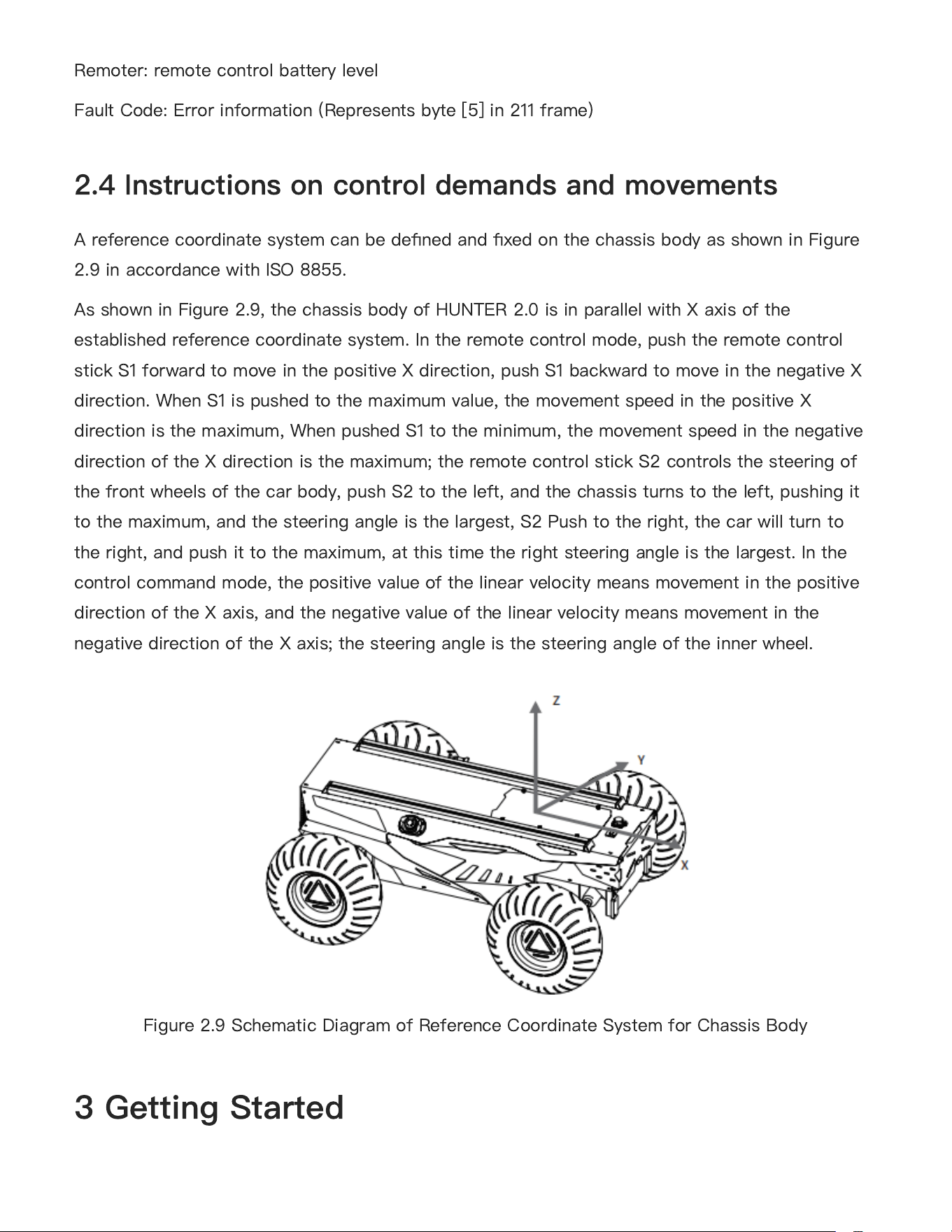
A reference coordinate system can be de
fi
ned and
fi
xed on the chassis body as shown in Figure
2.9 in accordance with ISO 8855.
As shown in Figure 2.9, the chassis body of HUNTER 2.0 is in parallel with X axis of the
established reference coordinate system. In the remote control mode, push the remote control
stick S1 forward to move in the positive X direction, push S1 backward to move in the negative X
direction. When S1 is pushed to the maximum value, the movement speed in the positive X
direction is the maximum, When pushed S1 to the minimum, the movement speed in the negative
direction of the X direction is the maximum; the remote control stick S2 controls the steering of
the front wheels of the car body, push S2 to the left, and the chassis turns to the left, pushing it
to the maximum, and the steering angle is the largest, S2 Push to the right, the car will turn to
the right, and push it to the maximum, at this time the right steering angle is the largest. In the
control command mode, the positive value of the linear velocity means movement in the positive
direction of the X axis, and the negative value of the linear velocity means movement in the
negative direction of the X axis; the steering angle is the steering angle of the inner wheel.
Figure 2.9 Schematic Diagram of Reference Coordinate System for Chassis Body
2.4 Instructions on control demands and movements
3 Getting Started
18
This section introduces the basic operation and development of the HUNTER 2.0 platform using
the CAN bus interface.
The basic operating procedure of startup is shown as follows:
Check
Check the condition of HUNTER 2.0. Check whether there are signi
fi
cant anomalies; if so,
please contact the after-sale service personal for support;
Check the state of emergency-stop switches. Make sure both emergency stop buttons are
released;
For
fi
rst-time use, check whether Q3 (drive power supply switch) on the rear panel has been
pressed down; if so, please release it, and then the drive will be powered o
ff
.
Startup
Press Q3 button, and normally, the voltmeter will display correct battery voltage and front
and rear lights will be both switched on;
Check the battery voltage, the normally voltage range is 24~26.8V, if there is continuous
“
beep-beep-beep...
”
sound from beeper,it means the battery voltage is low, please charge
the battery.
Shutdown
Press the button Q3 to cut o
ff
the power supply.
Emergency stop
Press down emergency push button on the top of HUNTER 2.0 chassis body.
Basic operating procedure of remote control
After the chassis of HUNTER 2.0 mobile robot is started correctly, turn on the RC
transmitter and push the SWB to the remote control mode, then, HUNTER 2.0 platform
movement can be controlled by the RC transmitter.
Parking
3.1 Use and operation
●
●
●
●
●
●
●
●
19
The parking brake adopts a power o
ff
electromagnetic band type brake to realize the parking
function, so when the chassis is running, the parking function must be turned o
ff
before
moving;
In the remote control mode, SWA is the parking function switch. You can control movement
after turning the stick to the top to turn o
ff
the parking function. Turn the stick to the
bottom to turn on the parking mode, if the chassis speed is not 0 at this time, it will
automatically decelerate to 0 and turn on the parking function.
In the command mode, the parking mode is the default when the power is turned on. At this
time, there is no response to the speed command, and the parking release command needs
to be sent before the speed command can be sent for control. If you need to park after the
motion control is completed, just send a parking command.
When the emergency stop is triggered, the parking will automatically start. At this time,
released the emergency stop, no matter where the remote control SWA is located, it needs
to be unlocked again for normal movement. If the power fails to be re-powered after a
power failure (such as low battery voltage), you can use the Q2 knob switch to manually
unlock the parking to facilitate moving the chassis or trailer. It should be noted that the
manual (tail knob switch Q2) unlocking the parking has the highest priority, which will
invalidate the parking in the program, so it is limited to special circumstances. Please close
it in time after use.
Ramp parking, when HUNTER 2.0 is on the slope, if the speed is 0, HUNTER 2.0 will check
the current automatically. When it reaches a certain value and continues for a period of time,
HUNTER 2.0 will turn on the ramp parking function automatically. After receiving the motion
command again, the ramp parking will relieve automatically and start to running.
HUNTER 2.0 products are equipped with a 10A charger by default, which can meet the charging
needs of customers. During normal charging, there is no indicator light on the chassis to indicate
the charging status of the vehicle. Please judge whether it is currently charging according to the
charger status indicator light.
The detailed operating procedure of charging is shown as follows:
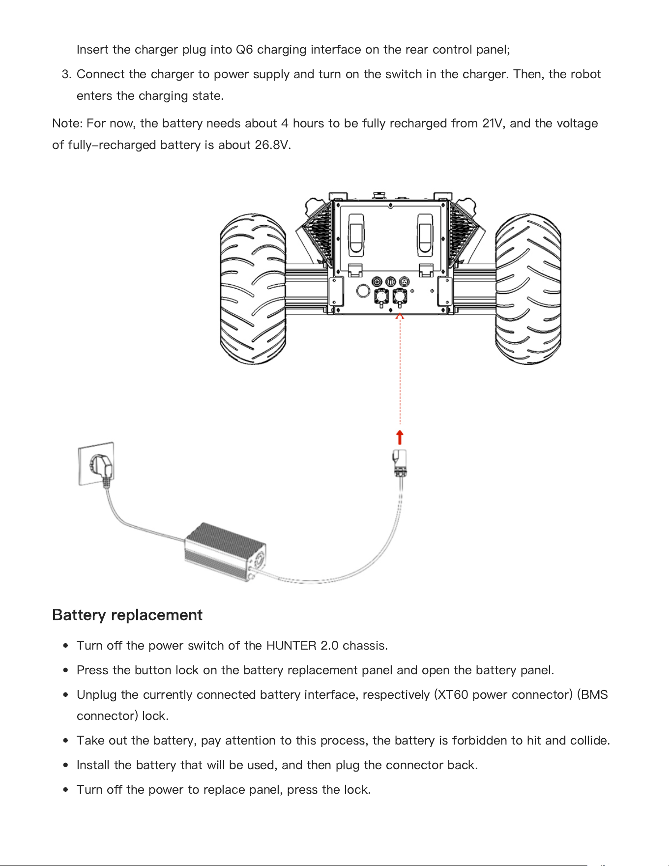
1.
Make sure the electricity of HUNTER 2.0 chassis is powered o
ff
. Before charging, please
make sure the power switch in the rear control console is turned o
ff
;
●
●
●
●
●
3.2 Charging and battery replacement
20
2.
Insert the charger plug into Q6 charging interface on the rear control panel;
3.
Connect the charger to power supply and turn on the switch in the charger. Then, the robot
enters the charging state.
Note: For now, the battery needs about 4 hours to be fully recharged from 21V, and the voltage
of fully-recharged battery is about 26.8V.
Battery replacement
Turn o
ff
the power switch of the HUNTER 2.0 chassis.
Press the button lock on the battery replacement panel and open the battery panel.
Unplug the currently connected battery interface, respectively (XT60 power connector) (BMS
connector) lock.
Take out the battery, pay attention to this process, the battery is forbidden to hit and collide.
Install the battery that will be used, and then plug the connector back.
Turn o
ff
the power to replace panel, press the lock.
●
●
●
●
●
●
21
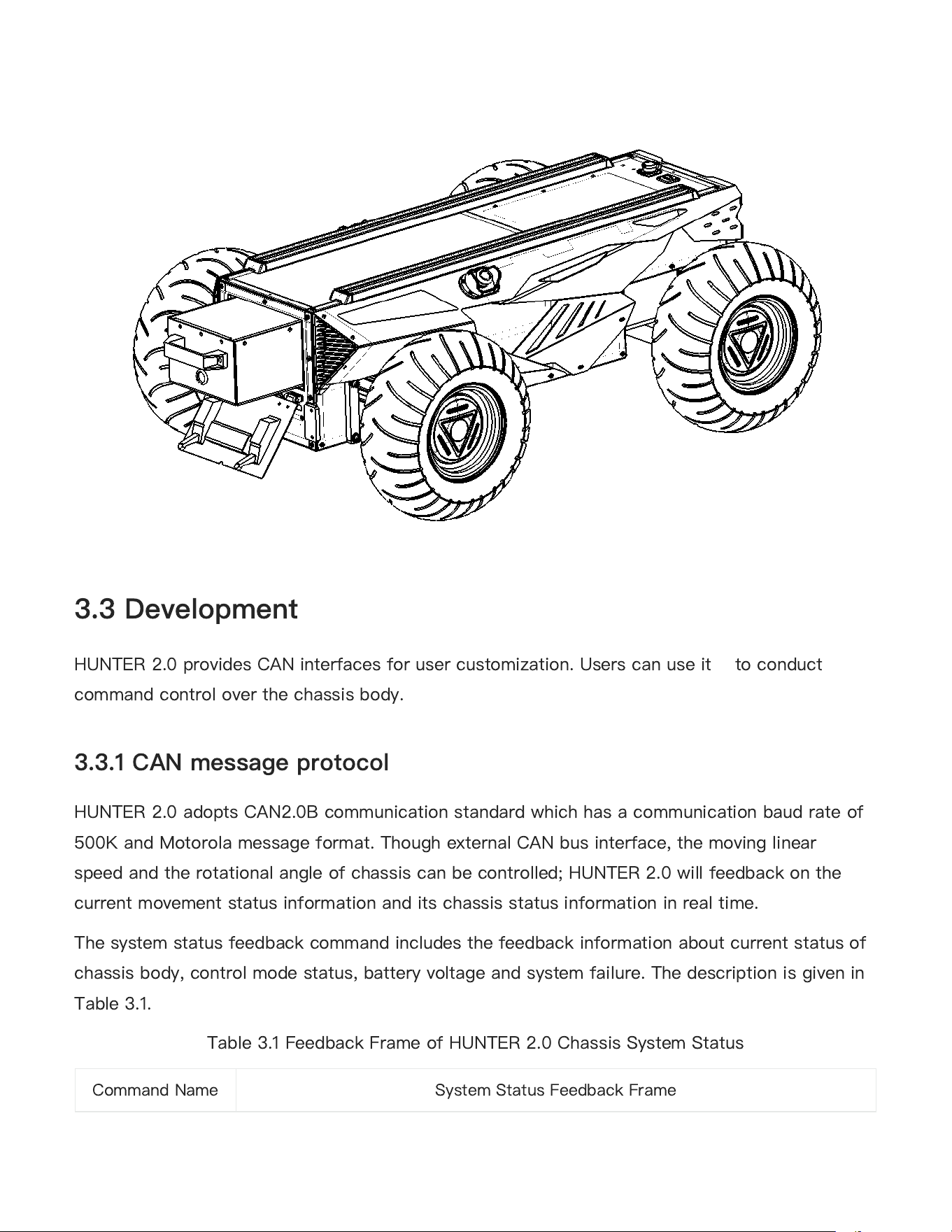
HUNTER 2.0 provides CAN interfaces for user customization. Users can use it to conduct
command control over the chassis body.
HUNTER 2.0 adopts CAN2.0B communication standard which has a communication baud rate of
500K and Motorola message format. Though external CAN bus interface, the moving linear
speed and the rotational angle of chassis can be controlled; HUNTER 2.0 will feedback on the
current movement status information and its chassis status information in real time.
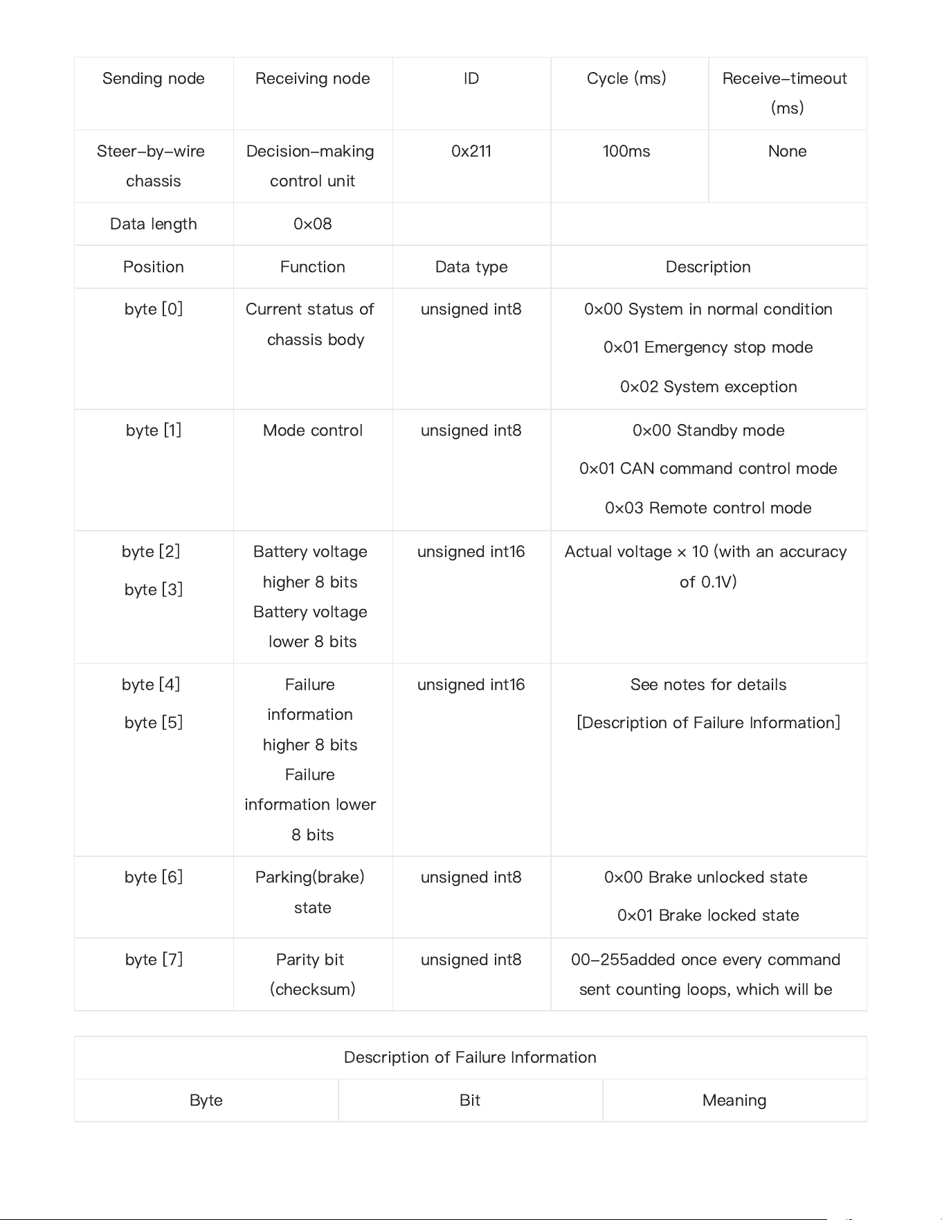
The system status feedback command includes the feedback information about current status of
chassis body, control mode status, battery voltage and system failure. The description is given in
Table 3.1.
Table 3.1 Feedback Frame of HUNTER 2.0 Chassis System Status
3.3 Development
3.3.1 CAN message protocol
Command Name
System Status Feedback Frame
22
Sending node
Receiving node
ID
Cycle (ms)
Receive-timeout
(ms)
Steer-by-wire
chassis
Decision-making
control unit
0x211
100ms
None
Data length
0×08
Position
Function
Data type
Description
byte [0]
Current status of
chassis body
unsigned int8
0×00 System in normal condition
0×01 Emergency stop mode
0×02 System exception
byte [1]
Mode control
unsigned int8
0×00 Standby mode
0×01 CAN command control mode
0×03 Remote control mode
byte [2]
byte [3]
Battery voltage
higher 8 bits
Battery voltage
lower 8 bits
unsigned int16
Actual voltage × 10 (with an accuracy
of 0.1V)
byte [4]
byte [5]
Failure
information
higher 8 bits
Failure
information lower
8 bits
unsigned int16
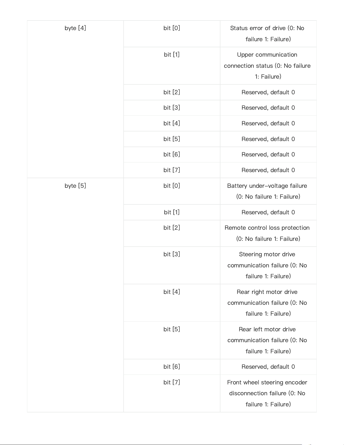
See notes for details
[Description of Failure Information]
byte [6]
Parking(brake)
state
unsigned int8
0×00 Brake unlocked state
0×01 Brake locked state
byte [7]
Parity bit
(checksum)
unsigned int8
00-255added once every command
sent counting loops, which will be
Description of Failure Information
Byte
Bit
Meaning
23
byte [4]
bit [0]
Status error of drive (0: No
failure 1: Failure)
bit [1]
Upper communication
connection status (0: No failure
1: Failure)
bit [2]
Reserved, default 0
bit [3]
Reserved, default 0
bit [4]
Reserved, default 0
bit [5]
Reserved, default 0
bit [6]
Reserved, default 0
bit [7]
Reserved, default 0
byte [5]
bit [0]
Battery under-voltage failure
(0: No failure 1: Failure)
bit [1]
Reserved, default 0
bit [2]
Remote control loss protection
(0: No failure 1: Failure)
bit [3]
Steering motor drive
communication failure (0: No
failure 1: Failure)
bit [4]
Rear right motor drive
communication failure (0: No
failure 1: Failure)
bit [5]
Rear left motor drive
communication failure (0: No
failure 1: Failure)
bit [6]
Reserved, default 0
bit [7]
Front wheel steering encoder
disconnection failure (0: No
failure 1: Failure)
24
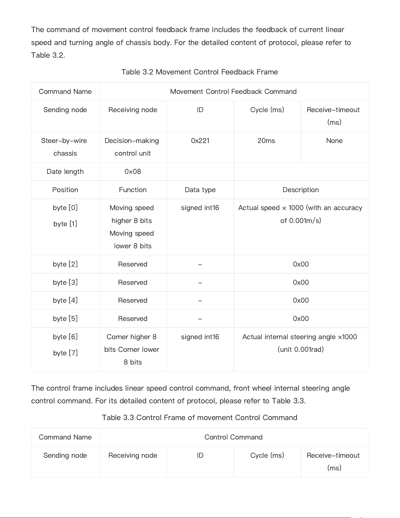
The command of movement control feedback frame includes the feedback of current linear
speed and turning angle of chassis body. For the detailed content of protocol, please refer to
Table 3.2.
Table 3.2 Movement Control Feedback Frame
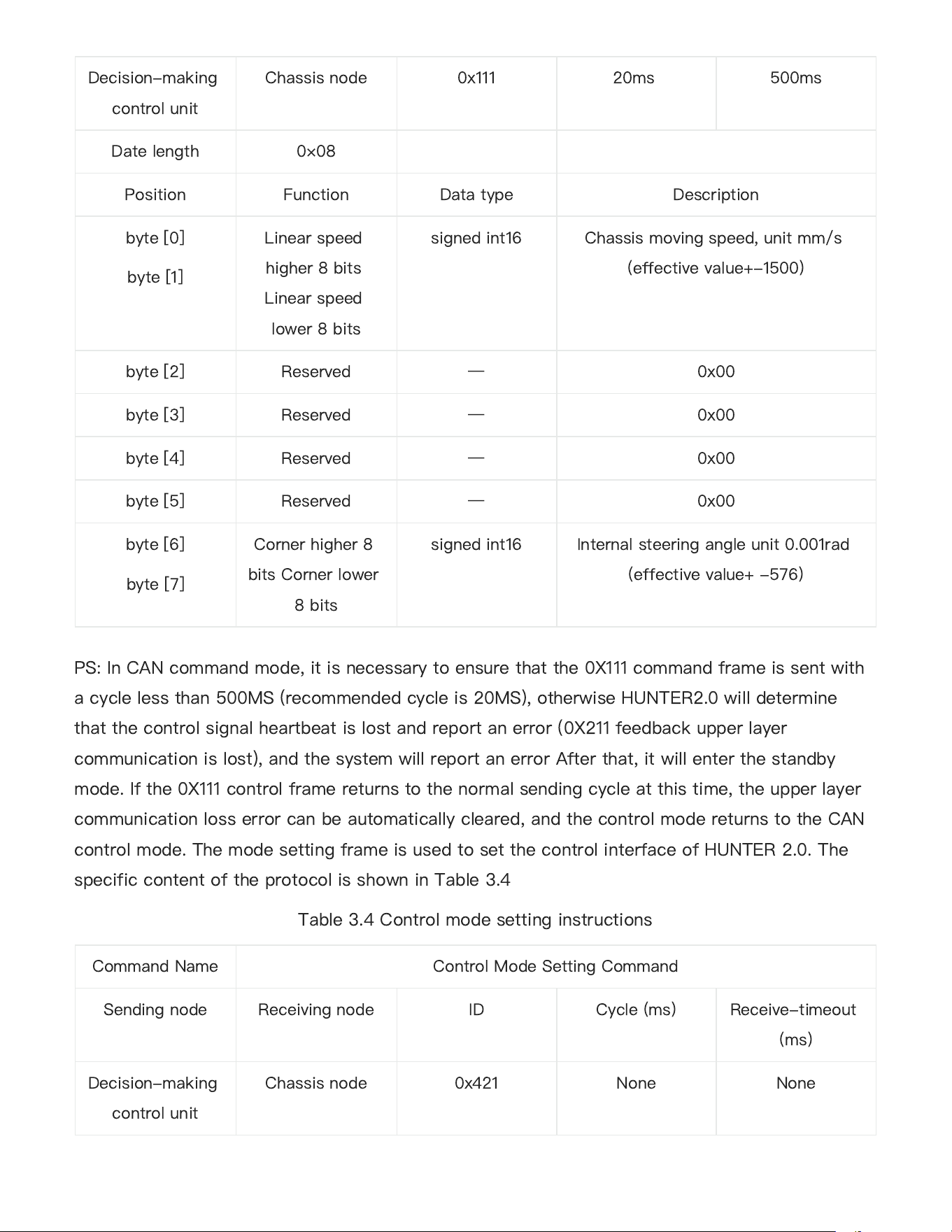
The control frame includes linear speed control command, front wheel internal steering angle
control command. For its detailed content of protocol, please refer to Table 3.3.
Table 3.3 Control Frame of movement Control Command
Command Name
Movement Control Feedback Command
Sending node
Receiving node
ID
Cycle (ms)
Receive-timeout
(ms)
Steer-by-wire
chassis
Decision-making
control unit
0x221
20ms
None
Date length 0×08
Position
Function
Data type
Description
byte [0]
byte [1]
Moving speed
higher 8 bits
Moving speed
lower 8 bits
signed int16
Actual speed × 1000 (with an accuracy
of 0.001m/s)
byte [2]
Reserved
-
0x00
byte [3]
Reserved
-
0x00
byte [4]
Reserved
-
0x00
byte [5]
Reserved
-
0x00
byte [6]
byte [7]
Corner higher 8
bits Corner lower
8 bits
signed int16
Actual internal steering angle ×1000
(unit 0.001rad)
Command Name
Control Command
Sending node
Receiving node
ID
Cycle (ms)
Receive-timeout
(ms)
25
PS: In CAN command mode, it is necessary to ensure that the 0X111 command frame is sent with
a cycle less than 500MS (recommended cycle is 20MS), otherwise HUNTER2.0 will determine
that the control signal heartbeat is lost and report an error (0X211 feedback upper layer
communication is lost), and the system will report an error After that, it will enter the standby
mode. If the 0X111 control frame returns to the normal sending cycle at this time, the upper layer
communication loss error can be automatically cleared, and the control mode returns to the CAN
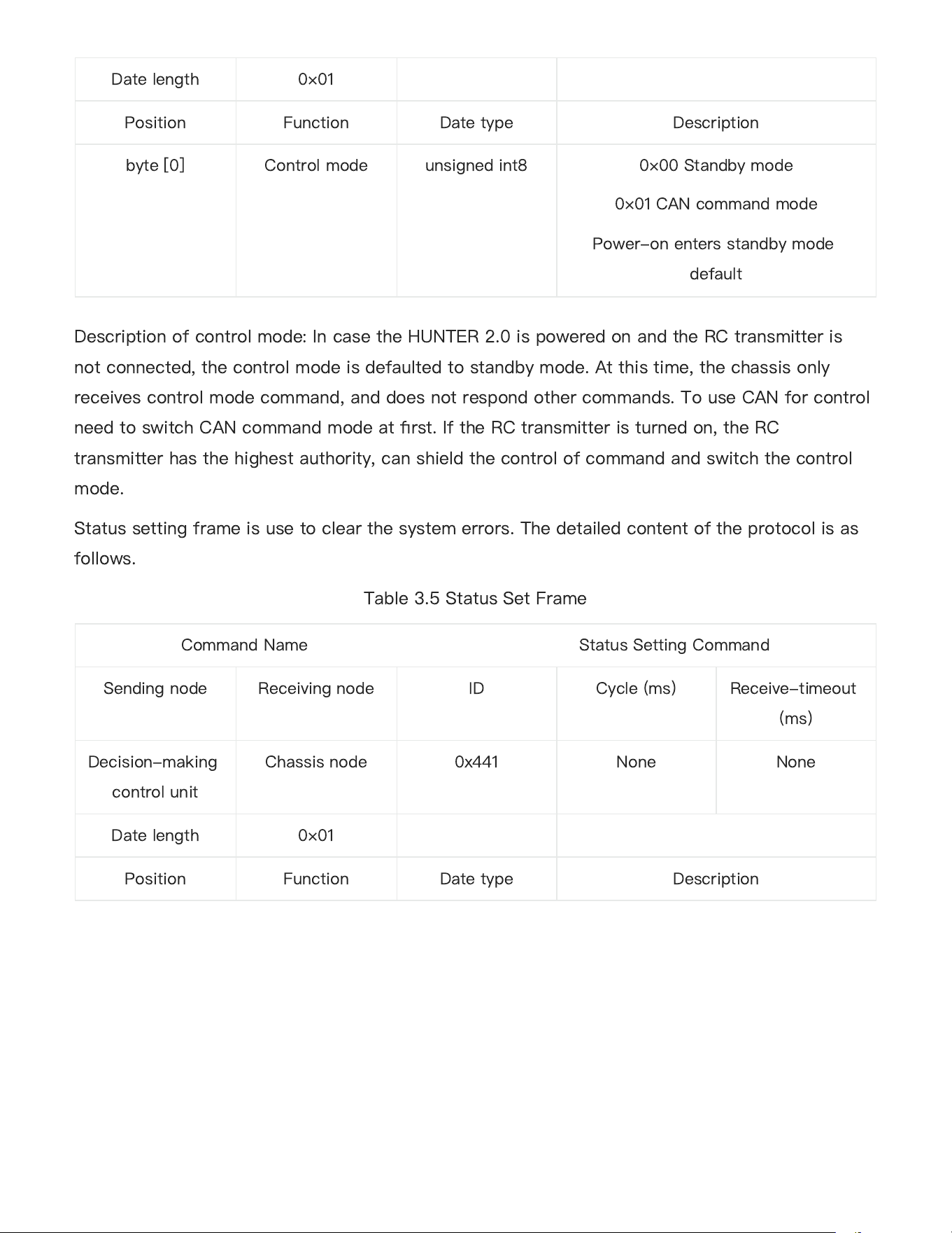
control mode. The mode setting frame is used to set the control interface of HUNTER 2.0. The
specific content of the protocol is shown in Table 3.4
Table 3.4 Control mode setting instructions
Decision-making
control unit
Chassis node
0x111
20ms
500ms
Date length 0×08
Position
Function
Data type
Description
byte [0]
byte [1]
Linear speed
higher 8 bits
Linear speed
lower 8 bits
signed int16
Chassis moving speed, unit mm/s
(effective value+-1500)
byte [2]
Reserved
—
0x00
byte [3]
Reserved
—
0x00
byte [4]
Reserved
—
0x00
byte [5]
Reserved
—
0x00
byte [6]
byte [7]
Corner higher 8
bits Corner lower
8 bits
signed int16
Internal steering angle unit 0.001rad
(effective value+ -576)
Command Name
Control Mode Setting Command
Sending node
Receiving node
ID
Cycle (ms)
Receive-timeout
(ms)
Decision-making
control unit
Chassis node
0x421
None
None
26
Description of control mode: In case the HUNTER 2.0 is powered on and the RC transmitter is
not connected, the control mode is defaulted to standby mode. At this time, the chassis only
receives control mode command, and does not respond other commands. To use CAN for control
need to switch CAN command mode at
fi
rst. If the RC transmitter is turned on, the RC
transmitter has the highest authority, can shield the control of command and switch the control
mode.
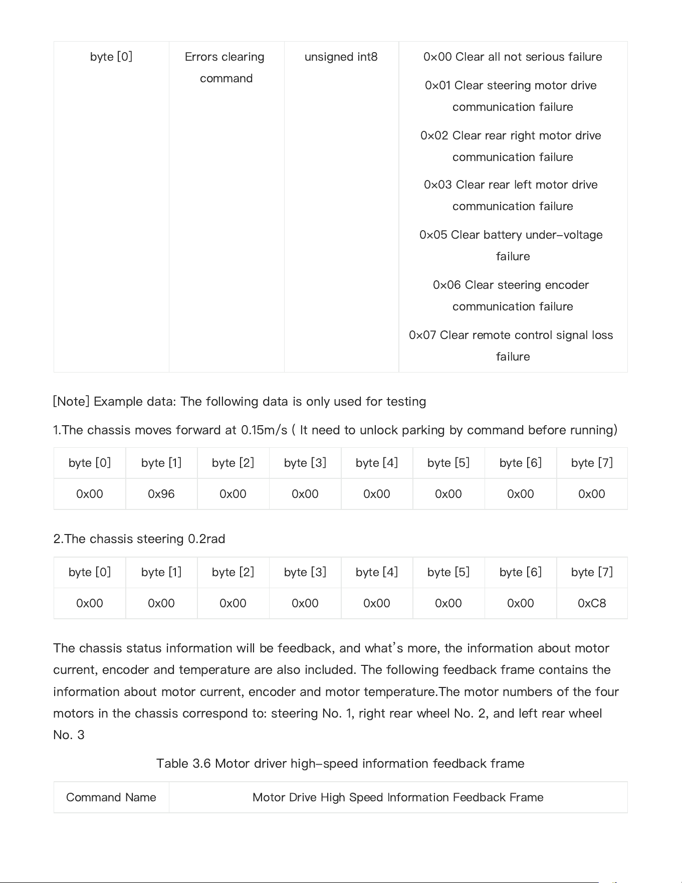
Status setting frame is use to clear the system errors. The detailed content of the protocol is as
follows.
Table 3.5 Status Set Frame
Date length 0×01
Position
Function
Date type
Description
byte [0]
Control mode
unsigned int8
0×00 Standby mode
0×01 CAN command mode
Power-on enters standby mode
default
Command Name Status Setting Command
Sending node
Receiving node
ID
Cycle (ms)
Receive-timeout
(ms)
Decision-making
control unit
Chassis node
0x441
None
None
Date length 0×01
Position
Function
Date type
Description
27
[Note] Example data: The following data is only used for testing
1.The chassis moves forward at 0.15m/s ( It need to unlock parking by command before running)
2.The chassis steering 0.2rad
The chassis status information will be feedback, and what
’
s more, the information about motor
current, encoder and temperature are also included. The following feedback frame contains the
information about motor current, encoder and motor temperature.The motor numbers of the four
motors in the chassis correspond to: steering No. 1, right rear wheel No. 2, and left rear wheel
No. 3
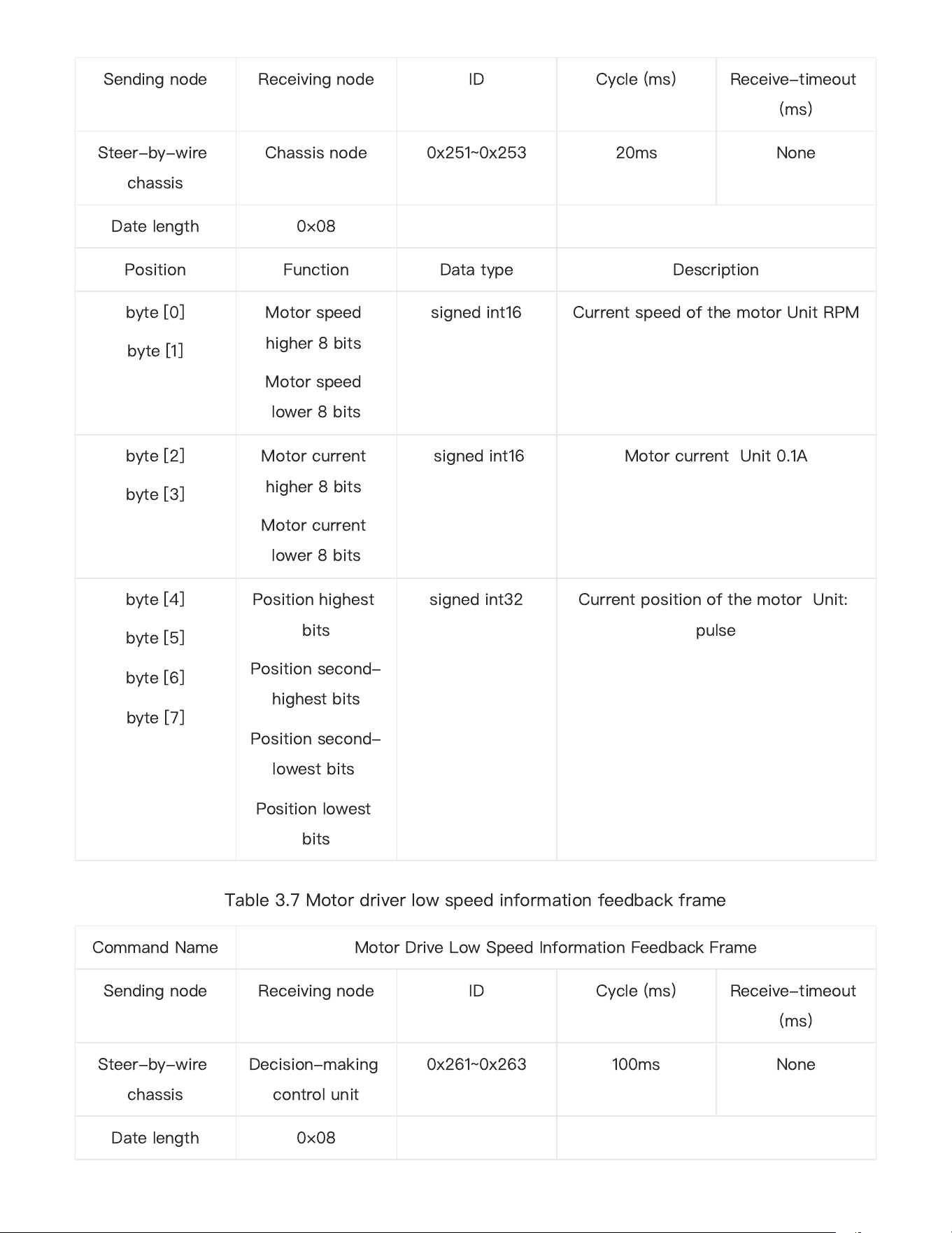
Table 3.6 Motor driver high-speed information feedback frame
byte [0]
Errors clearing
command
unsigned int8
0×00 Clear all not serious failure
0×01 Clear steering motor drive
communication failure
0×02 Clear rear right motor drive
communication failure
0×03 Clear rear left motor drive
communication failure
0×05 Clear battery under-voltage
failure
0×06 Clear steering encoder
communication failure
0×07 Clear remote control signal loss
failure
byte[0]
byte[1]
byte[2]
byte[3]
byte[4]
byte[5]
byte[6]
byte[7]
0x00
0x96
0x00
0x00
0x00
0x00
0x00
0x00
byte[0]
byte[1]
byte[2]
byte[3]
byte[4]
byte[5]
byte[6]
byte[7]
0x00
0x00
0x00
0x00
0x00
0x00
0x00
0xC8
Command Name
Motor Drive High Speed Information Feedback Frame
28
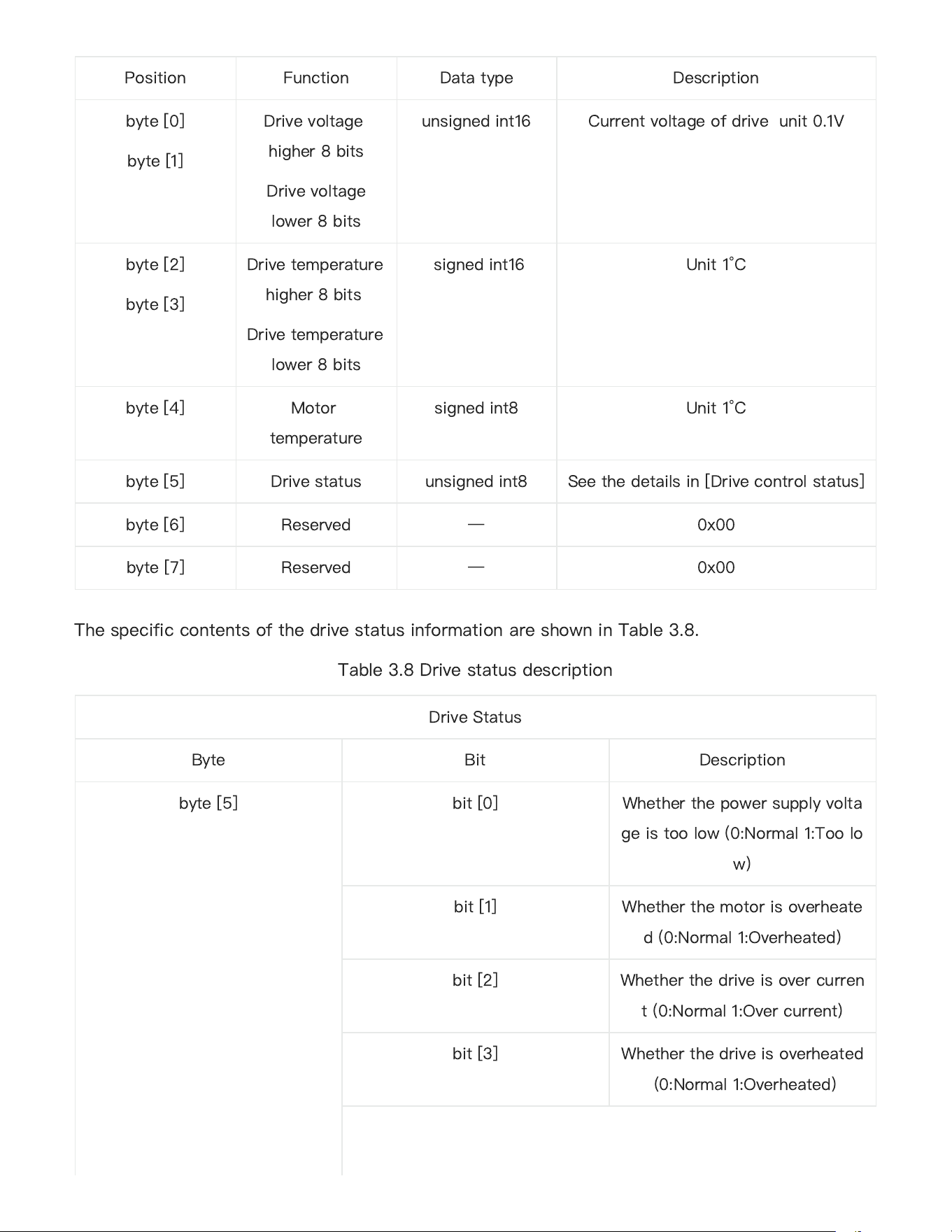
Table 3.7 Motor driver low speed information feedback frame
Sending node
Receiving node
ID
Cycle (ms)
Receive-timeout
(ms)
Steer-by-wire
chassis
Chassis node
0x251~0x253
20ms
None
Date length 0×08
Position
Function
Data type
Description
byte [0]
byte [1]
Motor speed
higher 8 bits
Motor speed
lower 8 bits
signed int16
Current speed of the motor Unit RPM
byte [2]
byte [3]
Motor current
higher 8 bits
Motor current
lower 8 bits
signed int16
Motor current Unit 0.1A
byte [4]
byte [5]
byte [6]
byte [7]
Position highest
bits
Position second-
highest bits
Position second-
lowest bits
Position lowest
bits
signed int32
Current position of the motor Unit:
pulse
Command Name
Motor Drive Low Speed Information Feedback Frame
Sending node
Receiving node
ID
Cycle (ms)
Receive-timeout
(ms)
Steer-by-wire
chassis
Decision-making
control unit
0x261~0x263
100ms
None
Date length 0×08
29
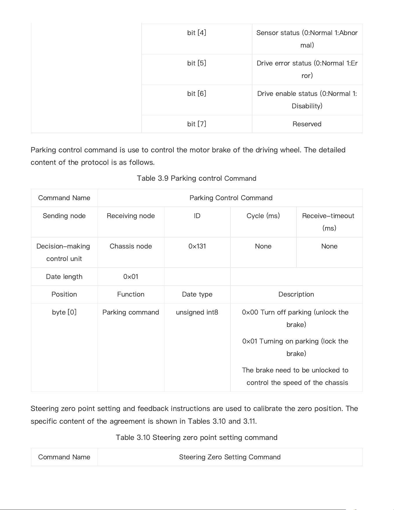
The specific contents of the drive status information are shown in Table 3.8.
Table 3.8 Drive status description
Position
Function
Data type
Description
byte [0]
byte [1]
Drive voltage
higher 8 bits
Drive voltage
lower 8 bits
unsigned int16
Current voltage of drive unit 0.1V
byte [2]
byte [3]
Drive temperature
higher 8 bits
Drive temperature
lower 8 bits
signed int16
Unit 1°C
byte [4]
Motor
temperature
signed int8
Unit 1°C
byte [5]
Drive status
unsigned int8
See the details in [Drive control status]
byte [6]
Reserved
—
0x00
byte [7]
Reserved
—
0x00
DriveStatus
Byte
Bit
Description
byte[5]
bit[0]
Whetherthepowersupplyvolta
geistoolow(0:Normal1:Toolo
w)
bit[1]
Whetherthemotorisoverheate
d(0:Normal1:Overheated)
bit[2]
Whetherthedriveisovercurren
t(0:Normal1:Overcurrent)
bit[3]
Whetherthedriveisoverheated
(0:Normal1:Overheated)
30
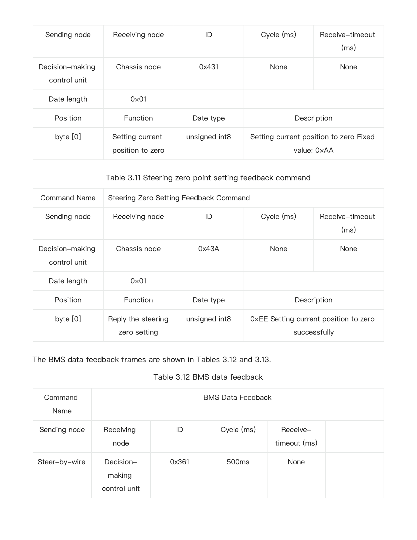
Parking control command is use to control the motor brake of the driving wheel. The detailed
content of the protocol is as follows.
Table 3.9 Parking control
Command
Steering zero point setting and feedback instructions are used to calibrate the zero position. The
specific content of the agreement is shown in Tables 3.10 and 3.11.
Table 3.10 Steering zero point setting command
bit[4]
Sensorstatus(0:Normal1:Abnor
mal)
bit[5]
Driveerrorstatus(0:Normal1:Er
ror)
bit[6]
Driveenablestatus(0:Normal1:
Disability)
bit[7]
Reserved
Command Name
Parking Control Command
Sending node
Receiving node
ID
Cycle (ms)
Receive-timeout
(ms)
Decision-making
control unit
Chassis node
0×131
None
None
Date length 0×01
Position
Function
Date type
Description
byte [0]
Parking command
unsigned int8
0×00 Turn off parking (unlock the
brake)
0×01 Turning on parking (lock the
brake)
The brake need to be unlocked to
control the speed of the chassis
Command Name
Steering Zero Setting Command
31
Table 3.11 Steering zero point setting feedback command
The BMS data feedback frames are shown in Tables 3.12 and 3.13.
Table 3.12 BMS data feedback
Sending node
Receiving node
ID
Cycle (ms)
Receive-timeout
(ms)
Decision-making
control unit
Chassis node
0x431
None
None
Date length 0×01
Position
Function
Date type
Description
byte [0]
Setting current
position to zero
unsigned int8
Setting current position to zero Fixed
value: 0×AA
Command Name
Steering Zero Setting Feedback Command
Sending node
Receiving node
ID
Cycle (ms)
Receive-timeout
(ms)
Decision-making
control unit
Chassis node
0x43A
None
None
Date length 0×01
Position
Function
Date type
Description
byte [0]
Reply the steering
zero setting
unsigned int8
0×EE Setting current position to zero
successfully
Command
Name
BMS Data Feedback
Sending node
Receiving
node
ID
Cycle (ms)
Receive-
timeout (ms)
Steer-by-wire
Decision-
making
control unit
0x361
500ms
None
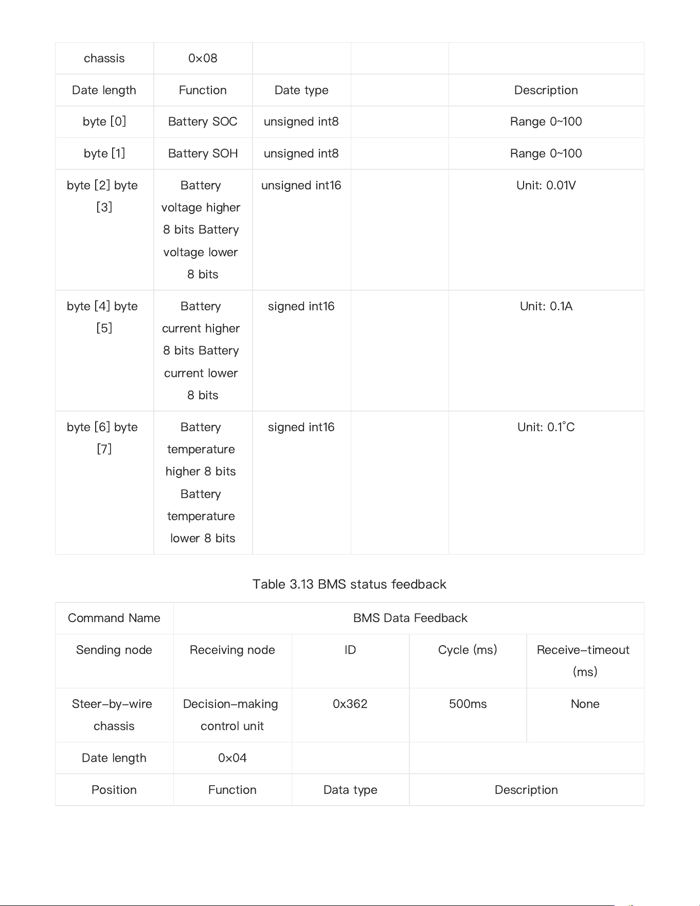
32
Table 3.13 BMS status feedback
chassis
0×08
Date length
Function
Date type
Description
byte [0]
Battery SOC
unsigned int8
Range 0~100
byte [1]
Battery SOH
unsigned int8
Range 0~100
byte [2] byte
[3]
Battery
voltage higher
8 bits Battery
voltage lower
8 bits
unsigned int16
Unit: 0.01V
byte [4] byte
[5]
Battery
current higher
8 bits Battery
current lower
8 bits
signed int16
Unit: 0.1A
byte [6] byte
[7]
Battery
temperature
higher 8 bits
Battery
temperature
lower 8 bits
signed int16
Unit: 0.1°C
Command Name
BMS Data Feedback
Sending node
Receiving node
ID
Cycle (ms)
Receive-timeout
(ms)
Steer-by-wire
chassis
Decision-making
control unit
0x362
500ms
None
Date length 0×04
Position
Function
Data type
Description
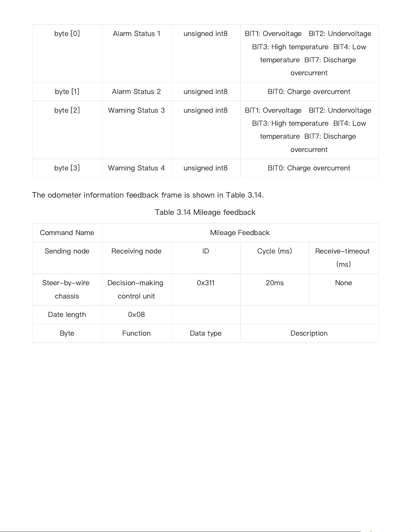
33
The odometer information feedback frame is shown in Table 3.14.
Table 3.14 Mileage feedback
byte [0]
Alarm Status 1
unsigned int8
BIT1: Overvoltage BIT2: Undervoltage
BIT3: High temperature BIT4: Low
temperature BIT7: Discharge
overcurrent
byte [1]
Alarm Status 2
unsigned int8
BIT0: Charge overcurrent
byte [2]
Warning Status 3
unsigned int8
BIT1: Overvoltage BIT2: Undervoltage
BIT3: High temperature BIT4: Low
temperature BIT7: Discharge
overcurrent
byte [3]
Warning Status 4
unsigned int8
BIT0: Charge overcurrent
Command Name
Mileage Feedback
Sending node
Receiving node
ID
Cycle (ms)
Receive-timeout
(ms)
Steer-by-wire
chassis
Decision-making
control unit
0x311
20ms
None
Date length 0×08
Byte
Function
Data type
Description
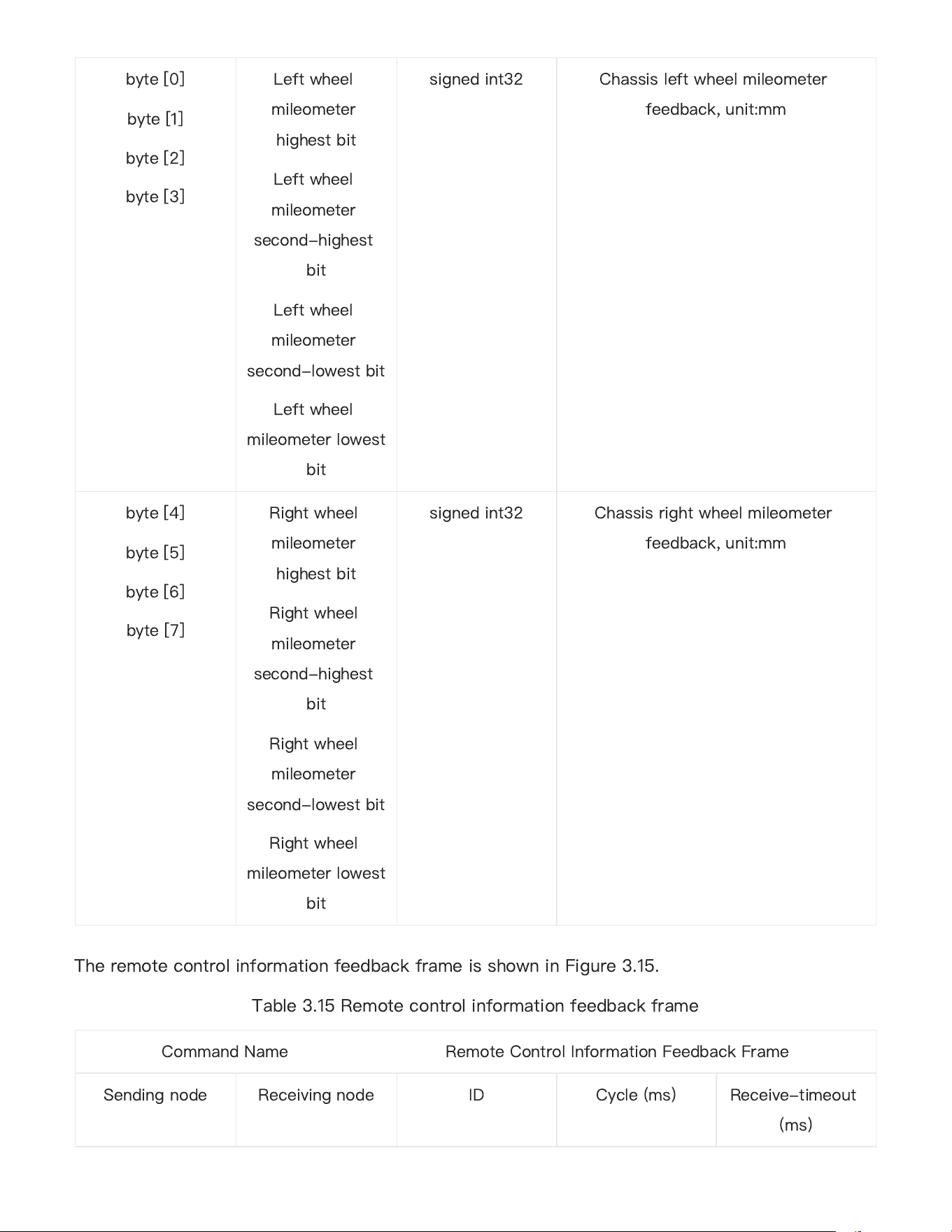
34
The remote control information feedback frame is shown in Figure 3.15.
Table 3.15 Remote control information feedback frame
byte [0]
byte [1]
byte [2]
byte [3]
Left wheel
mileometer
highest bit
Left wheel
mileometer
second-highest
bit
Left wheel
mileometer
second-lowest bit
Left wheel
mileometer lowest
bit
signed int32
Chassis left wheel mileometer
feedback, unit:mm
byte [4]
byte [5]
byte [6]
byte [7]
Right wheel
mileometer
highest bit
Right wheel
mileometer
second-highest
bit
Right wheel
mileometer
second-lowest bit
Right wheel
mileometer lowest
bit
signed int32
Chassis right wheel mileometer
feedback, unit:mm
CommandName RemoteControl InformationFeedback Frame
Sending node
Receiving node
ID
Cycle (ms)
Receive-timeout
(ms)
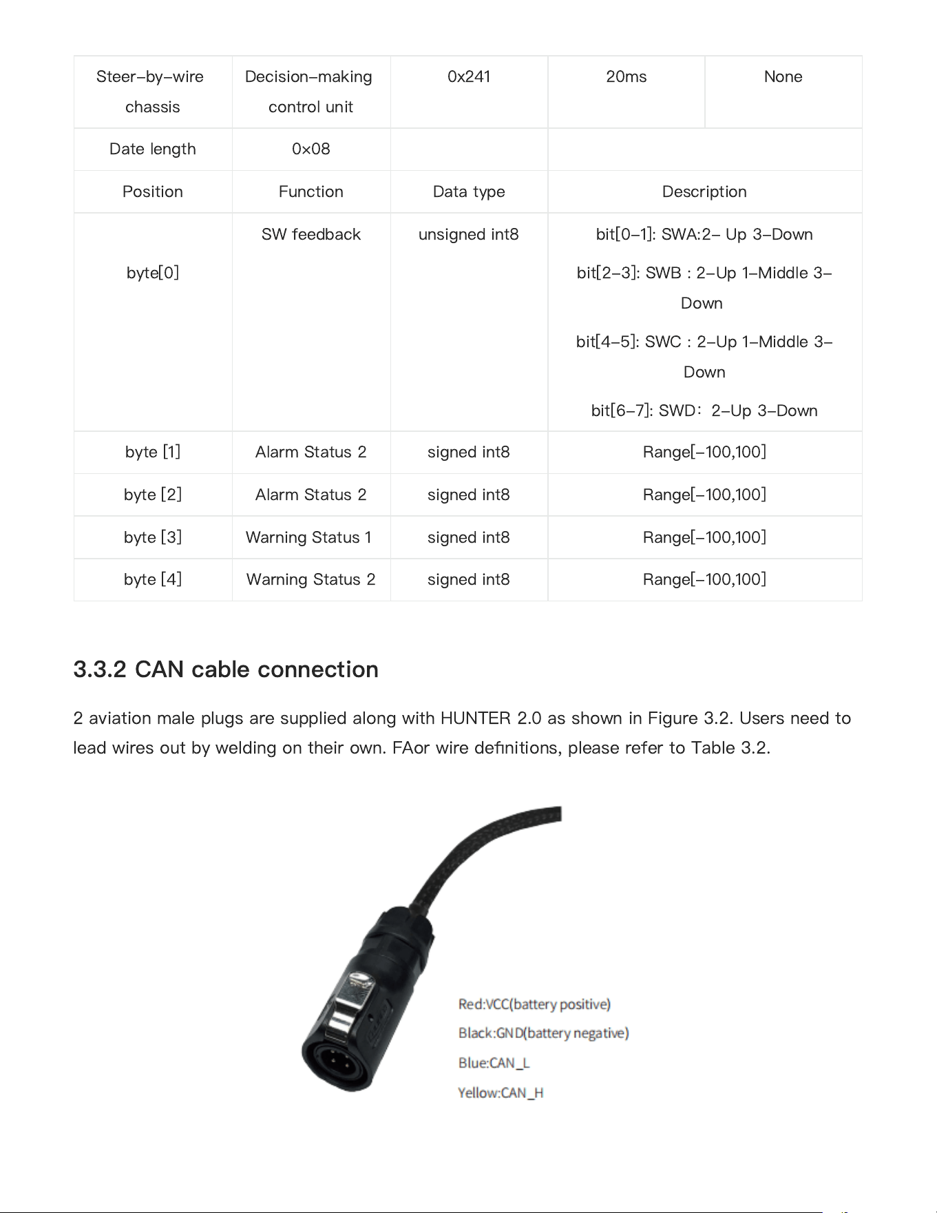
35
2 aviation male plugs are supplied along with HUNTER 2.0 as shown in Figure 3.2. Users need to
lead wires out by welding on their own. FAor wire de
fi
nitions, please refer to Table 3.2.
3.3.2 CAN cable connection
Steer-by-wire
chassis
Decision-making
control unit
0x241
20ms
None
Date length 0×08
Position
Function
Data type
Description
byte[0]
SWfeedback
unsignedint8
bit[0-1]: SWA:2- Up 3-Down
bit[2-3]:SWB:2-Up1-Middle3-
Down
bit[4-5]:SWC:2-Up1-Middle3-
Down
bit[6-7]:SWD
:
2-Up3-Down
byte [1]
Alarm Status 2
signed int8
Range[-100,100]
byte [2]
Alarm Status 2
signed int8
Range[-100,100]
byte [3]
Warning Status 1
signed int8
Range[-100,100]
byte [4]
Warning Status 2
signed int8
Range[-100,100]
36
Figure 3.2 Schematic Diagram of Aviation Male Plug
Correctly start the chassis of HUNTER 2.0 mobile robot, and turn on RC transmitter. Then,
switch to the command control mode, i.e. toggling S1 mode of RC transmitter to the top. At this
point, HUNTER 2.0 chassis will accept the command from CAN interface, and the host can also
parse the current state of chassis with the real-time data fed back from CAN bus. For the
detailed content of protocol, please refer to CAN communication protocol.
In order to facilitate users to upgrade the
fi
rmware version used by HUNTER 2.0 and bring
customers a more complete experience, HUNTER 2.0 provides a
fi
rmware upgrade hardware
interface and corresponding client software.
Upgrade Preparation
AgilexCAN debugging moduleX 1
Micro USB cableX 1
HUNTER 2.0 chassisX 1
A computer (WINDOWS OS (Operating System))X 1
Upgrade Process
1.Plug in the USBTOCAN module on the computer, and then open the
AgxCandoUpgradeToolV1.3_boxed.exesoftware (the sequence cannot be wrong, first open the
software and then plug in the module, the device will not be recognized).
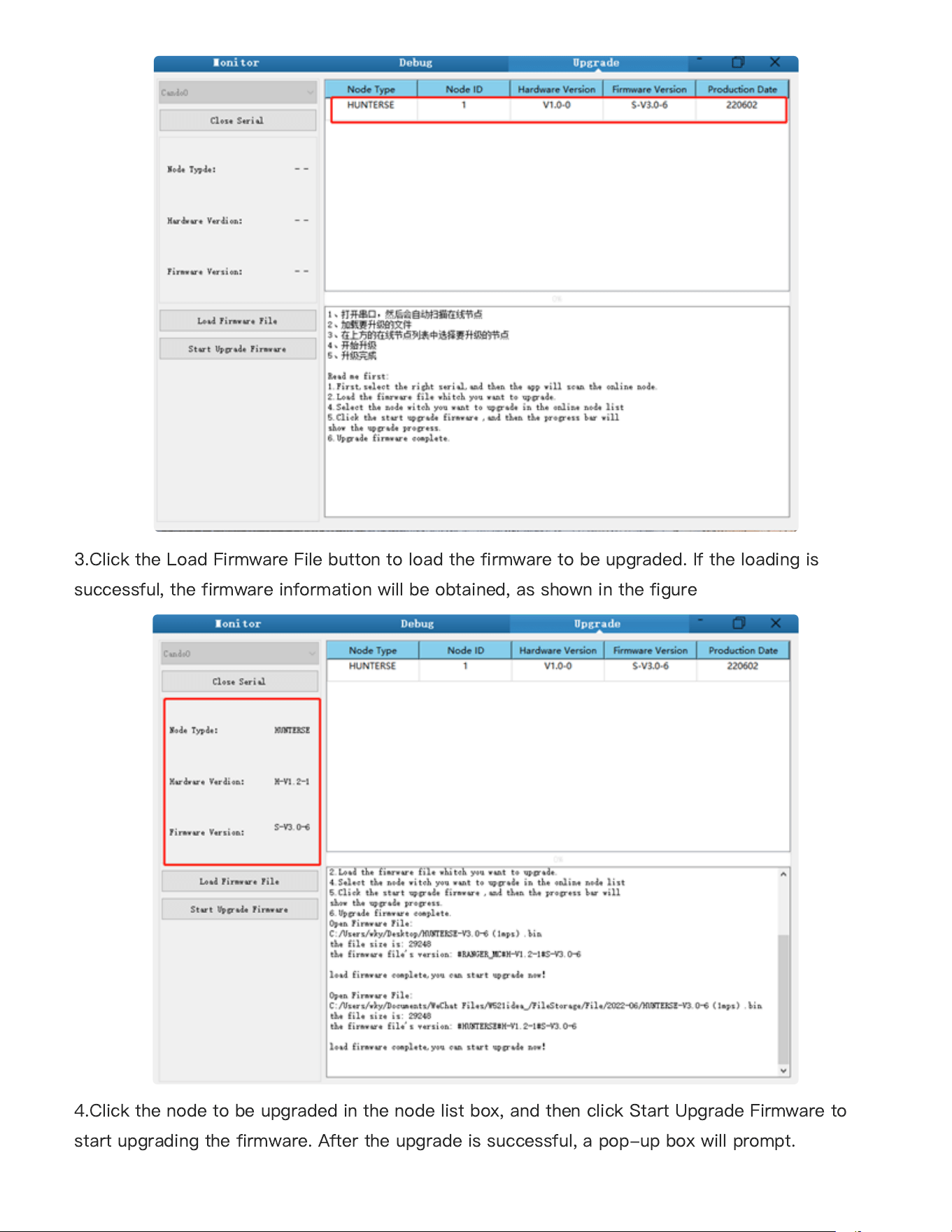
2.Click the Open Serialbutton, and then press the power button on the car body. If the
connection is successful, the version information of the main control will be recognized, as
shown in the figure.
3.3.3 Implementation of CAN command control
3.4 Firmware upgrades
●
●
●
●
37
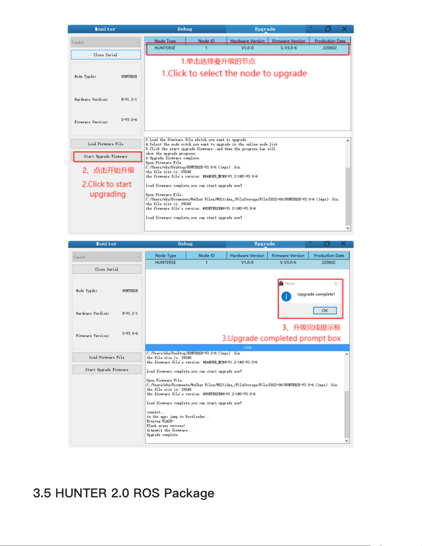
3.Click the Load Firmware Filebutton to load the firmware to be upgraded. If the loading is
successful, the firmware information will be obtained, as shown in the figure
4.Click the node to be upgraded in the node list box, and then click Start Upgrade Firmware to
start upgrading the firmware. After the upgrade is successful, a pop-up box will prompt.
38
3.5 HUNTER 2.0 ROS Package
39
ROS provide some standard operating system services, such as hardware abstraction, low-level
device control, implementation of common function, interprocess message and data packet
management. ROS is based on a graph architecture, so that process of di
ff
erent nodes can
receive, and aggregate various information (such as sensing, control, status, planning, etc.)
Currently ROS mainly support UBUNTU.
Development Preparation
Hardware preparation
CANlight can communication module ×1
Thinkpad E470 notebook ×1
AGILEX HUNTER 2.0 mobile robot chassis ×1
AGILEX HUNTER 2.0 remote control FS-i6s ×1
AGILEX HUNTER 2.0 top aviation power socket ×1
Use example environment description
Ubuntu 18.04 LTS
ROS melodic
Git
Hardware connection and preparation
Lead out the CAN wire of the HUNTER 2.0 top aviation plug or the tail plug, and connect
CAN_H and CAN_L in the CAN wire to the CAN_TO_USB adapter respectively;
Turn on the knob switch on the HUNTER 2.0 mobile robot chassis, and check whether the
emergency stop switches on both sides are released
;
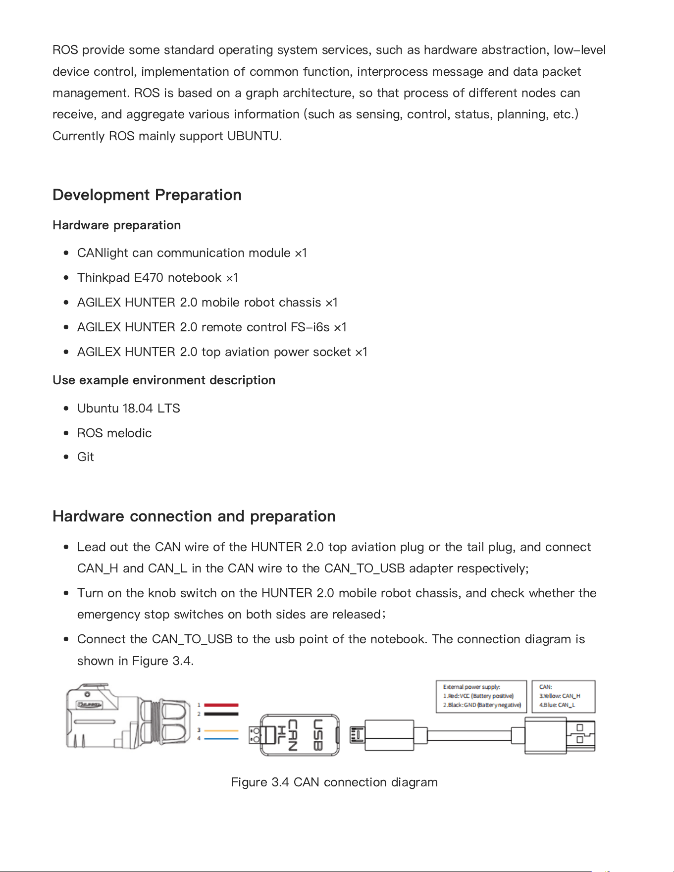
Connect the CAN_TO_USB to the usb point of the notebook. The connection diagram is
shown in Figure 3.4.
Figure 3.4 CAN connection diagram
●
●
●
●
●
●
●
●
●
●
●
40
ROS installation and environment setting
For installation details, please refer to
http://wiki.ros.org/kinetic/Installation/Ubuntu
Test CANABLE hardware and CAN communication
Setting CAN-TO-USB adaptor
Enable gs_usb kernel module
sudo modprobe gs_usb
Setting 500k Baud rate and enable can-to-usb adaptor
sudo ip link set can0 up type can bitrate 500000
If no error occurred in the previous steps, you should be able to use the command to view
the can device immediately
ifconfig -a
Install and use can-utils to test hardware
sudo apt install can-utils
If the can-to-usb has been connected to the HUNTER 2.0 robot this time, and the car has
been turned on, use the following commands to monitor the data from the HUNTER 2.0
chassis
candump can0
Please refer to:
[1] https://github.com/agilexrobotics/agx_sdk
[2] https://wiki.rdu.im/_pages/Notes/Embedded-System/Li-nux/can-bus-in-linux.html
AGILEX HUNTER 2.0 ROS PACKAGE download and compile
Download ros package
$ sudo apt install -y ros-$ROS_DISTRO-teleop-twist-keyboard
Clone compile hunter_ros code
$ cd ~/catkin_ws/src
●
●
●
●
●
●
●
41
$ git clone https://github.com/agilexrobotics/ugv_sdk.git
$ git clone https://github.com/agilexrobotics/hunter_ros.git
$ cd ..
$ catkin_make
Please refer to: https://github.com/agilexrobotics/hunter_2_ros
Start the ROS node
Start the based node
$ roslaunch hunter_bringup hunter_robot_base.launch
Start the keyboard remote operation node
$ roslaunch hunter_bringup hunter_teleop_keyboard.launch
Github ROS development package directory and usage instructions
*_base:: The core node for the chassis to send and receive hierarchical CAN messages. Based
on the communication mechanism of ros, it can control the movement of the chassis and read
the status of the bunker through the topic.
*_msgs: Define the specific message format of the chassis status feedback topic.
*_bringup: startup files for chassis nodes and keyboard control nodes, and scripts to enable the
usb_to_can module.
Q: HUNTER 2.0 is started up correctly, but why cannot the RC transmitter control the chassis
body to move?
A: First, check whether the drive power supply is in normal condition, whether the drive power
switch is pressed down and whether E-stop switches are released; then, check whether the
control mode selected with the top left mode selection switch on the RC transmitter is correct,
check whether the parking switch is turn o
ff
.
Q: HUNTER 2.0 remote control is in normal condition, and the information about chassis
status and movement can be received correctly, but when the control frame protocol is issued,
●
●
4 Q&A
42
why cannot the chassis body control mode be switched and the chassis respond to the control
frame protocol?
A: Normally, if HUNTER 2.0 can be controlled by a RC transmitter, it means the chassis
movement is under proper control; if the chassis feedback frame can be accepted, it means CAN
extension link is in normal condition. Please check the CAN control frame sent to see whether
the data check is correct and whether the control mode is in command control mode. You can
check the status of error
fl
ag from the error bit in the chassis status feedback frame.
Q: HUNTER 2.0 gives a "beep-beep-beep..." sound in operation, how to deal with this
problem?
A: If HUNTER 2.0 gives this "beep-beep-beep" sound continuously, it means the battery is in the
alarm voltage state. Please charge the battery in time.
5 Product Dimensions
5.1 Illustration diagram of product external dimensions
43
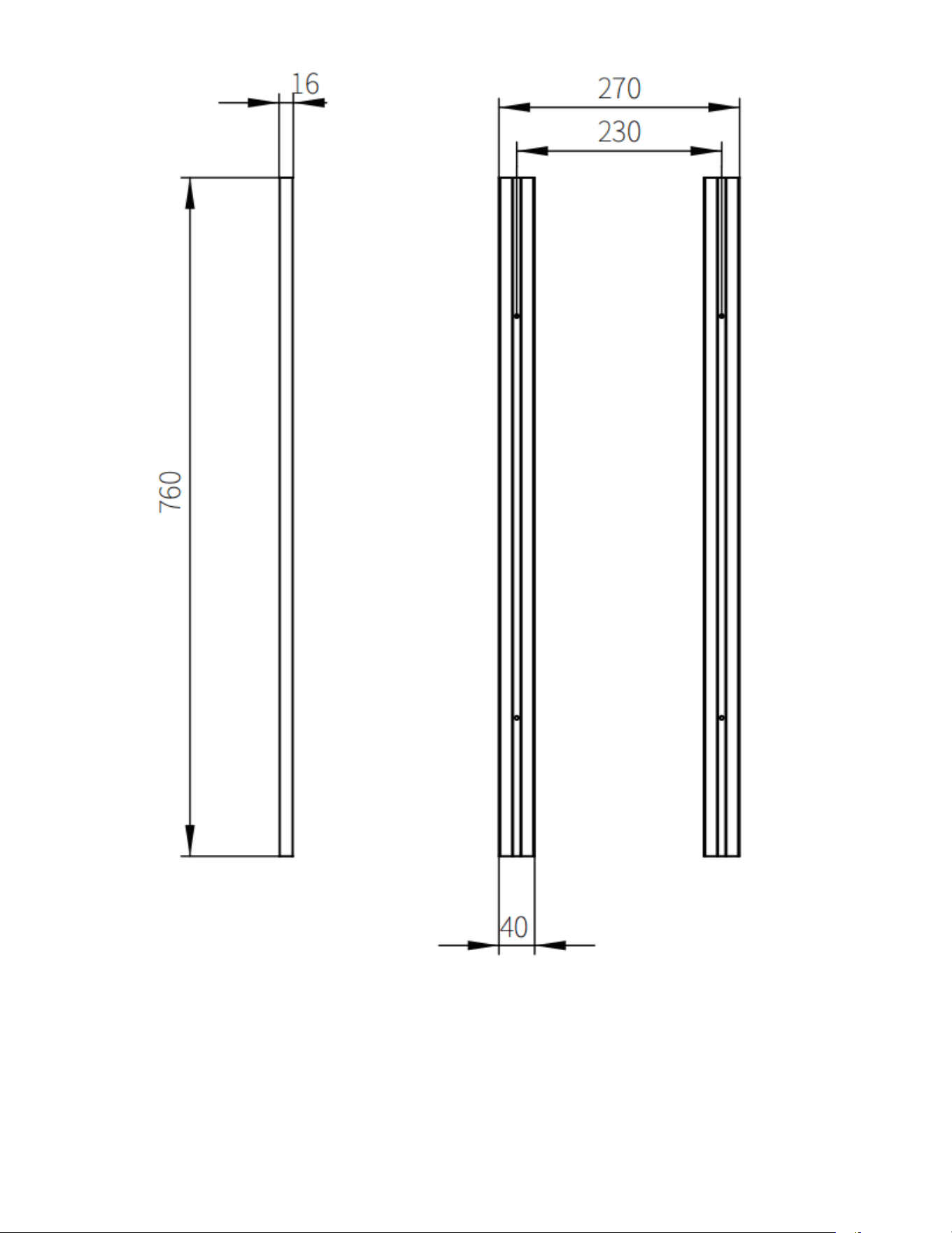
5.2 Illustration diagram of top extended support
dimensions
44
45

