1
R
ANGE
R
MINI
.
U
s
e
r
M
a
nu
al
R
ANGE
R
MINI
.
U
s
e
r
M
a
nu
al
D
o
c
um
e
nt
v
e
rs
i
on
I
mport
a
nt
S
afe
ty
I
n
f
orm
a
t
i
on
P
r
eca
ut
i
ons
CON
T
EN
TS
I
ntro
d
u
c
t
i
on
to
t
he
R
ANGE
R
MINI
.
.
P
ro
d
u
c
t
L
i
st
.
S
p
ecifica
t
i
ons
.
R
e
qu
i
r
ed
f
or
D
e
v
el
opm
e
nt
B
a
s
ic
I
ntro
d
u
c
t
i
on
.
S
t
a
tus
o
f
t
he
R
ANGE
R
MINI
.
.
D
e
s
c
r
i
pt
i
on
o
f
E
lec
tr
ical
I
nt
e
r
face
s
.
R
e
mot
e
C
ontro
l
I
nstru
c
t
i
ons
U
s
age
a
n
d
D
e
v
el
opm
e
nt
.
O
p
e
r
a
t
i
on
.
CAN C
ommun
ica
t
i
on
P
roto
c
o
l
.
R
ANGE
R
MINI
.
us
e
m
a
nu
al
f
or
R
O
S
.
F
i
rmw
a
r
e
U
p
g
r
ade
P
ro
d
u
c
t
S
i
z
e
RANGER MINI 3.0 User Manual
2
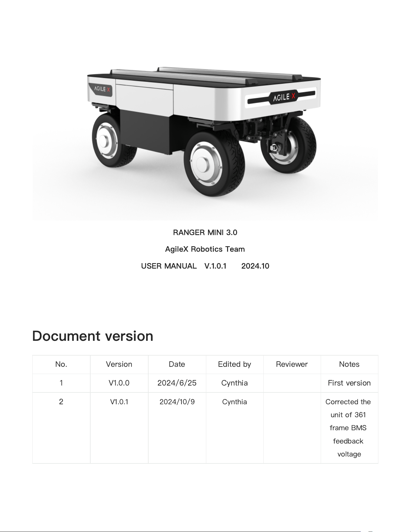
RANGER MINI 3.0
AgileXRoboticsTeam
USER MANUALV.1.0.1 2024.10
Document version
No. Version Date Edited by Reviewer Notes
1 V1.0.0 2024/6/25 Cynthia First version
2
V1.0.1
2024/10/9 Cynthia
Corrected the
unit of 361
frame BMS
feedback
voltage
3
Before using the robot, any individual or organization must read and understand the manual. If
you have any questions about it, please do not hesitate to contact us at support@agilex.ai. It is
very important that you shouldfollow and implement all instructions and guidelines in this
manual. Please pay extra attention to the warnings.
This manual does not cover the design, installation, and operation of a robotic application, nor
does it include any equipment that may affect the safety of a robotic system. A robotsystem
that uses the RANGER MINI 3.0should bedesigned and used in compliance with the safety
requirements and other standards of the corresponding countries.
Anyusersof the RANGER MINI 3.0should comply with laws and regulations of relevant countries
and ensure that there are no obvious hazards in the application of the RANGER MINI 3.0. This
includes but is not limited to the following:
E
ff
ectiveness and responsibility
Do a risk assessment of the robotic system that uses the RANGERMINI 3.0.
The risk assessment should include additional safety equipment to other machinery.
Please ensurethat the equipment of the whole robotic system, including software and
hardware, are designed, and installed correctly.
The RANGER MINI 3.0is notanautonomous mobile robot with anti-collision, anti-fall,
biological approach warning, and other safety functions. These safetyfunctions
areexpected to be developedand assessed by system integrators and end customers under
relevant safety regulations and laws to ensure there are not anymajor dangers and potential
safety hazards in their practical applications.
Read all technical documents: including the risk assessment and this manual.
Know the possible safety risks before using the RANGER MINI 3.0.
Use Environment
For the first use, please read this manual carefully to understand the basic operation and
operating specifications.
Remote control operation should be in a relatively open area. The RANGER MINI 3.0does
not have any automatic obstacle avoidance sensors.
Important Safety Information
●
●
●
●
●
●
●
●
4
Please use the RANGER MINI 3.0under the ambient temperature of -10
℃
~40
℃
.
The RANGERMINI 3.0
’
swaterproof and dustproof levelisIP54 if it is not customized.
Check
Make sure each device is fully charged.
Make sure the RANGER MINI 3.0 has no obvious abnormalities.
Make sure the remote control has sufficient battery power.
Operation Precautions
Ensure that the surrounding area is relatively open when operating the RANGER.
Please do remote control within sight.
The maximum load of the RANGER MINI 3.0is 120 KG. Please ensure that the payload does
not exceed 120 KG when using.
When installingexternal equipment on the RANGERMINI 3.0, Please ensure theircentroid
location is at the RANGERMINI 3.0
’
scenter of rotation.
Please charge the RANGER MINI 3.0in time after low-battery alarm.
When the RANGER MINI 3.0is abnormal, please stop using it immediately to avoid
secondary injury.
When the RANGER MINI 3.0is abnormal, please contact the technical support immediately,
and do not handle it without professional suggestion.
Please use the RANGER MINI 3.0in an environment that does not exceed itsIP protection
level.
Do not push the RANGER MINI 3.0directly.
The current of the tail extension power supply does not exceed 15A, and the total power
does not exceed 720w.
Battery
The battery of RANGER MINI products is not fully charged when it leaves the factory. The
specific battery voltage and power can be displayed through vol and batt on the RANGER
MINI remote control.
Please do not charge the battery after it is exhausted, please charge it in time when the low
battery of the RANGER MINI remote control is less than 15%
●
●
●
●
●
Precautions
●
●
●
●
●
●
●
●
●
●
●
●
5
Static storage conditions: The optimal storage temperature is -10
℃
~40
℃
. When the battery
is not in use, it must be charged and discharged once every month, and then stored at full
voltage. Do not store the battery Place in fire, or heat the battery. Do not store batteries at
high temperatures.
Charging: You must use the matching lithium battery charger for charging. Do not charge the
battery below 0°C. Do not use non-original standard batteries, power supplies, and chargers.
Usage environment
The operating temperature of RANGER MINI is -10°C~40°C, please do not use it in an
environment where the temperature is lower than -10°C and higher than 40°C
Do not use it in an environment with corrosive or flammable gases or near flammable
substances.
Please do not use it around heating elements such as heaters or large winding resistors
RANGER MINI is waterproof and dustproof rated IP54
It is recommended that the altitude of the use environment should not exceed 1000M
It is recommended that the temperature difference between day and night in the use
environment does not exceed 25
℃
Safety
If you have any questions about the use process, please follow the relevant instruction
manual or consult relevant technical personnel.
Before using the equipment, pay attention to the on-site conditions to avoid improper
operation that may cause personal safety problems.
In case of emergency, press the emergency stop button to power off the equipment.
Do not modify the internal equipment structure without technical support and permission
When the equipment is abnormal, please stop using it immediately to avoid secondary injury
When an abnormality occurs in the equipment, please contact the relevant technical
personnel and do not handle it without authorization.
●
●
●
●
●
●
●
●
●
●
●
●
●
●
CONTENTS
6
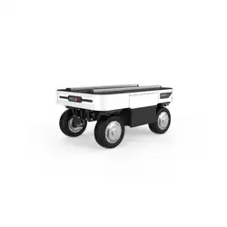
The RANGER MINI 3.0is a programmable omnidirectional UGV (UNMANNED GROUND VEHICLE),
which is a chassis with a modular design. Compared with the four-wheel differential chassis, the
RANGER MINI 3.0has obvious advantages when running on ordinary cement roadsand asphalt
roads. It not only has higher speed and load capacity, but also reduces the wear and tear on the
structure and tires. Itis also more stable and safer. Compared with Ackermann chassis,the
RANGER MINI3.0 not only reduces the turning radius, but also can turn at 0 angle.The RANGER
MINI 3.0combines the advantages of differential chassis and Ackermann chassis, which is
suitable for various complex terrains. What
’
smore, it can be equipped with stereo cameras,
LiDAR, GNSS, IMU, manipulators and other equipment to beapplied in fields such as unmanned
inspection, security, scientific research, exploration and logistics.
1 Introduction to theRANGERMINI 3.0
1.1 Product List
1.2 Specifications
Name Quantity
RANGER MINI 3 body ×1
Battery charger (AC 220V) ×1
Aviation plug male (4Pin) ×1
FS remote controller(optional) ×1
USB to CAN communication module ×1
Type
Items
Parameters
Mechanical
Dimensions (mm)
720×500×345
Axle Track (mm)
494
Front/rear track (mm)
364
Total weight (Kg)
75
7
Battery type
Lithium iron phosphate
Battery parameters
48V24AH
Power drive motor
350W×4
Steering drive motor
100W×4
Parkingtype
Electronic brake
Steering type
4 wheels steering
Suspension
Independent suspension
Steering motor reduction
ratio
1:51
Steering motor encoder
Dual Encoder
Drive motor reduction ratio
1:4.428
Drive motor sensor
Encoder
Performation
IP grade
IP54
Maximum speed
(
km/h
)
7.2
Minimum turning radius (mm)
0mm
(
Spin mode
)
810mm
(
Ackermann model
)
Maximum climbing abilitiy (°)
15° (25kg)
Crossing width
120mm
Ground clearance (mm)
105
Maximum endurance (h)
7
Maximum travel (km)
35
Charging time (h)
1.5
Working temperature (
℃
)
-10~40
Control
Control mode
Remote control mode
Command control mode
Remote controller
2.4G/limit distance 100M
8
The RANGER MINI 3.0can be equipped with FS remote control when buying. Users can use it to
control the 4WDchassis, complete mode switching, movement and steering. The RANGER MINI
3.0hasa standard CAN (Controller Area Network) communication interfaceto facilitate
secondary development.
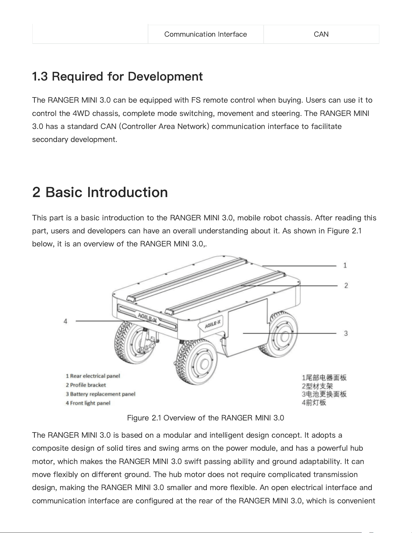
This part is a basic introduction to the RANGERMINI 3.0, mobile robot chassis. After reading this
part, users and developers can have an overall understanding about it. As shown in Figure 2.1
below, it is an overview of the RANGERMINI 3.0,.
Figure 2.1 Overview of the RANGERMINI 3.0
The RANGER MINI 3.0is based on a modular and intelligent design concept. It adopts a
composite design of solid tires and swing armsonthe power module, and has a powerful hub
motor, which makes the RANGER MINI 3.0 swift passing ability andground adaptability. It can
move flexibly on different ground. The hub motor does not requirecomplicated transmission
design, making the RANGER MINI 3.0smaller and more flexible. An open electrical interface and
communication interface are configured at the rear of the RANGERMINI 3.0, which is convenient
1.3 Required for Development
2 Basic Introduction
Communication Interface
CAN
9
for users to carry out secondary development. The electrical interface adopts aviation waterproof
connectors, which is not onlyconducive to the expansion and use, but also allows the RANGER
MINI 3.0tobe used in some harsh environments. A standard aluminum extension bracket is
installed on the RANGERMINI 3.0, which is convenient for users to carry external equipment.
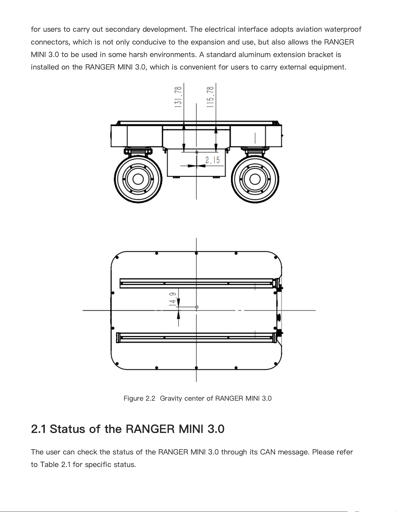
Figure 2.2 Gravity center of RANGERMINI 3.0
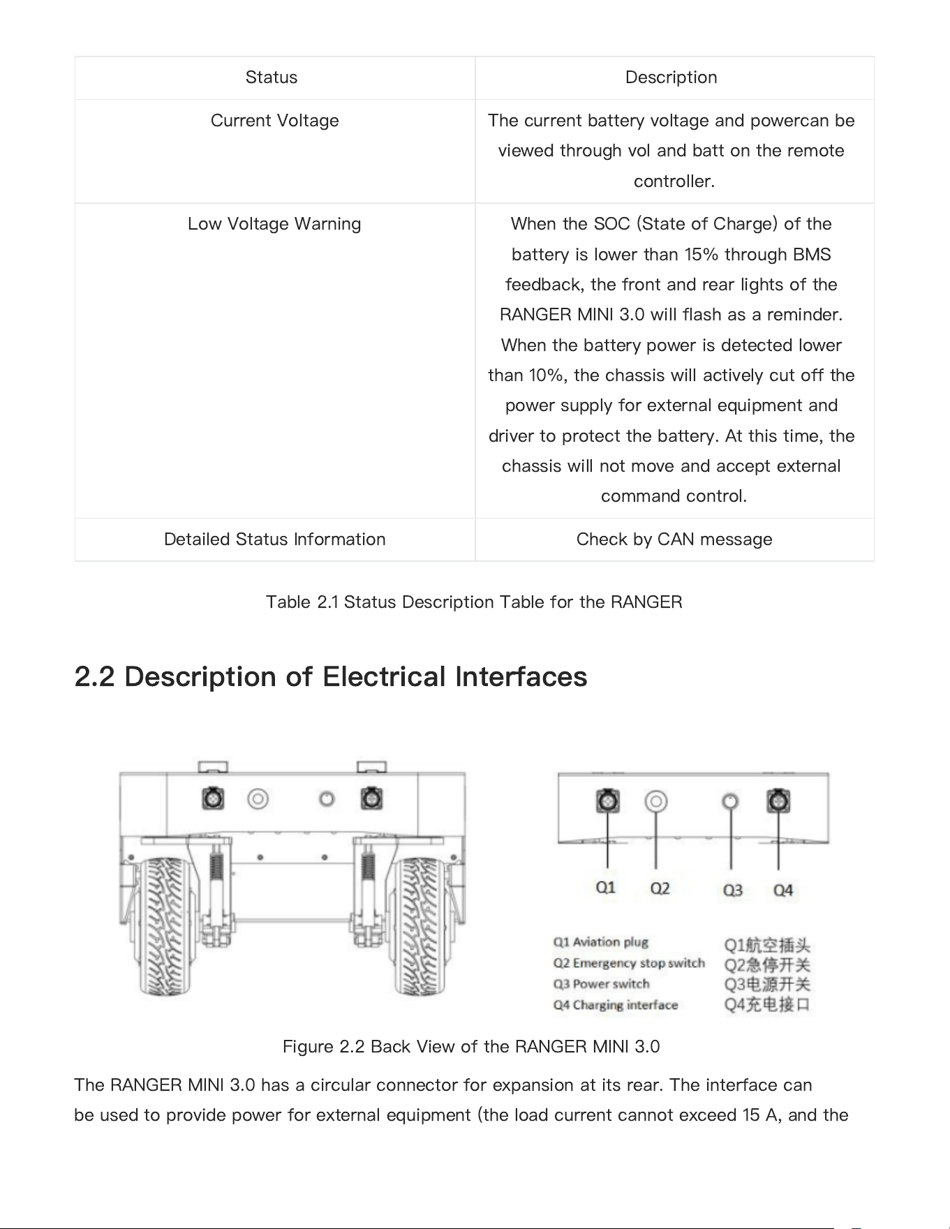
The user can check the status of the RANGER MINI 3.0through its CAN message. Please refer
to Table 2.1 for specific status.
2.1Status of the RANGERMINI 3.0
10
Table 2.1 Status Description Table for the RANGER
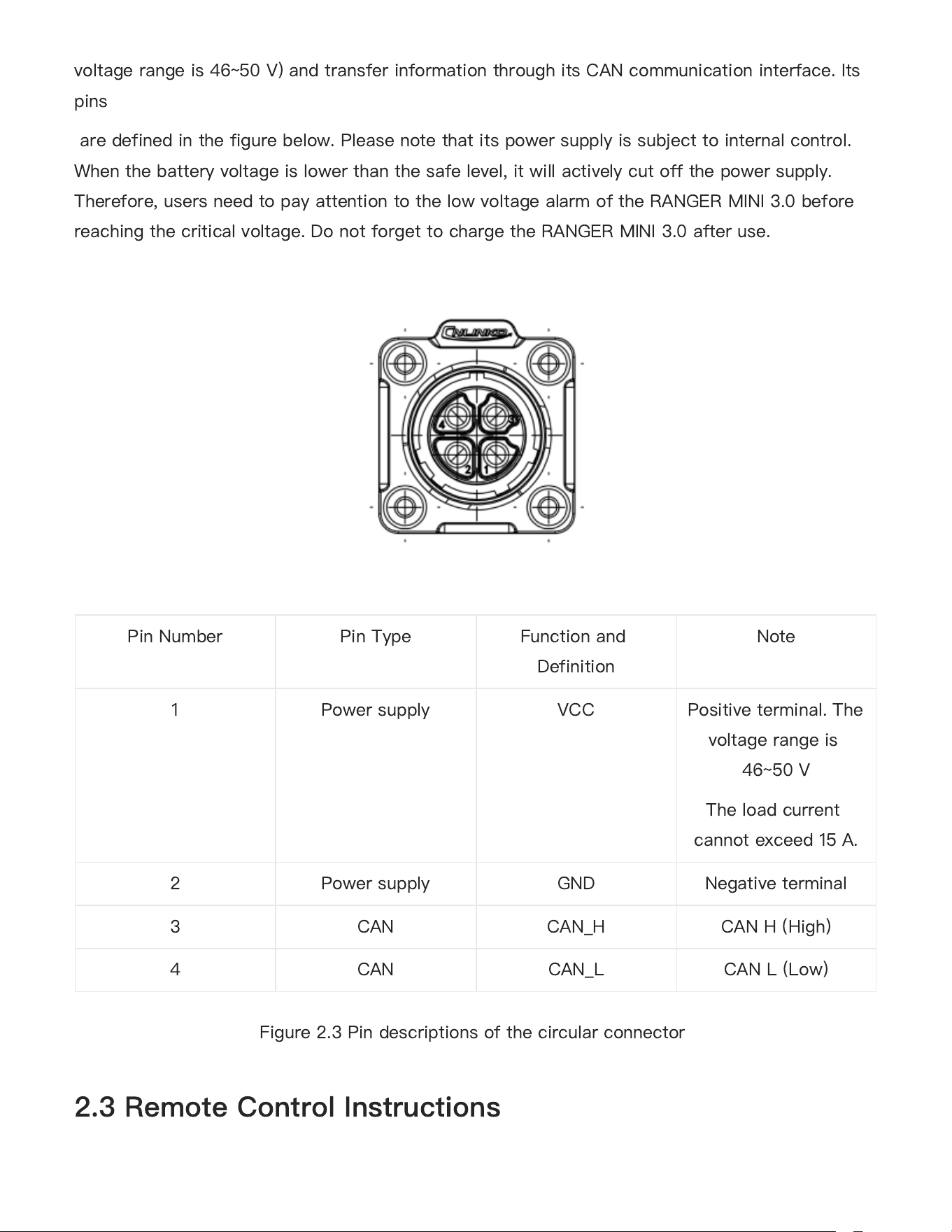
Figure 2.2 Back View of theRANGER MINI 3.0
The RANGER MINI 3.0has acircular connector for expansion at its rear. The interface can
beused to provide power for external equipment (the load current cannot exceed 15 A, and the
2.2 Description of Electrical Interfaces
Status Description
Current Voltage The current battery voltage and powercan be
viewed through vol and batt on the remote
controller.
Low Voltage Warning When the SOC (State of Charge) ofthe
battery is lower than 15% through BMS
feedback, the front and rear lights of the
RANGER MINI 3.0 will flash as a reminder.
When the battery power is detected lower
than 10%, the chassis will actively cut off the
power supply for external equipmentand
driver to protectthebattery. At this time, the
chassis will not move and accept external
command control.
Detailed Status Information Check by CAN message
11
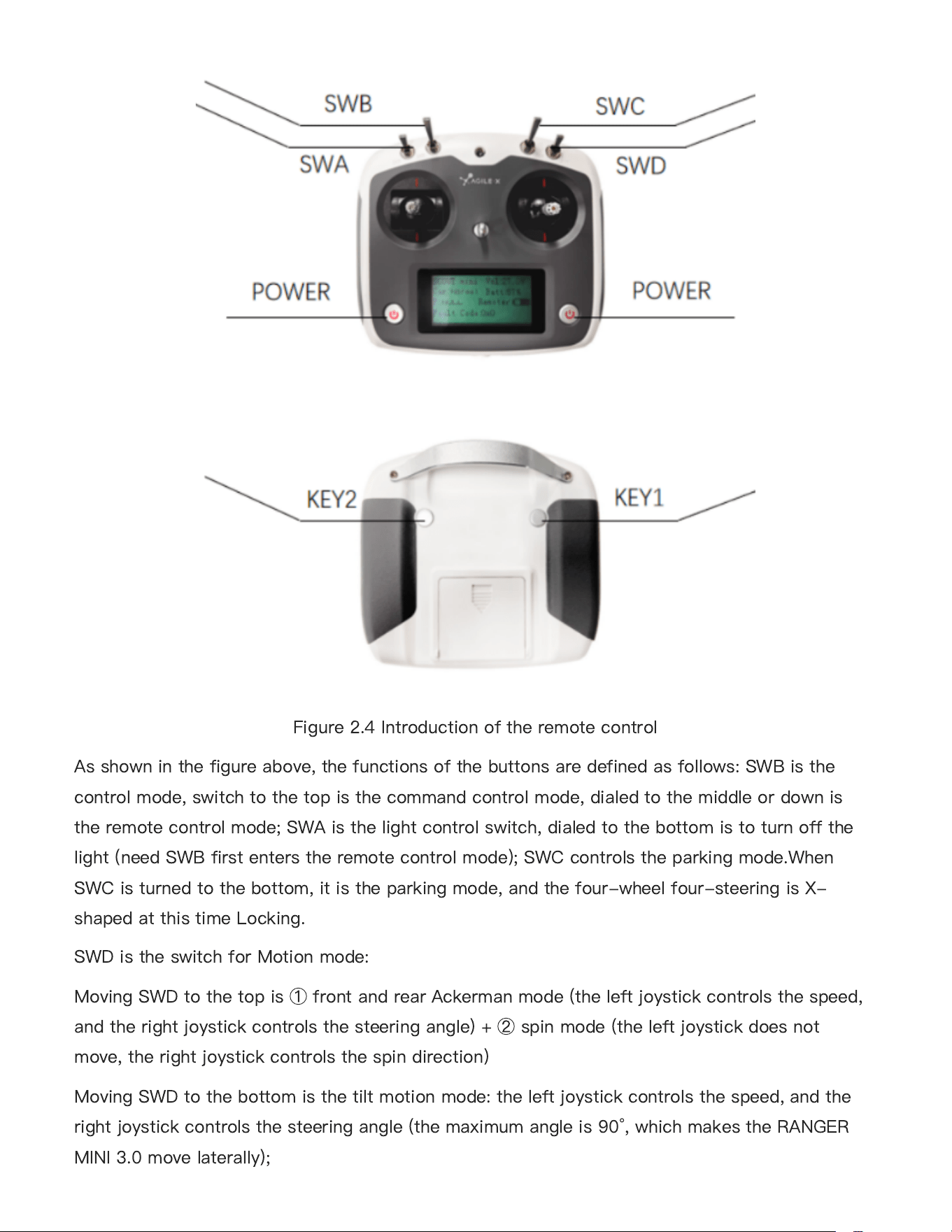
voltage range is 46~50 V) and transfer information through its CAN communication interface. Its
pins
are defined in the figure below. Please note that its power supply is subject to internal control.
When the battery voltage is lower than the safe level, it will actively cut off the power supply.
Therefore, users need to pay attention to the low voltage alarm of the RANGER MINI 3.0before
reaching the critical voltage. Do not forget to charge the RANGER MINI 3.0after use.
Figure 2.3 Pin descriptionsof the circular connector
2.3 Remote Control Instructions
Pin Number Pin Type Function and
Definition
Note
1 Power supply VCC Positiveterminal. The
voltage range is
46~50 V
The load current
cannot exceed 15 A.
2 Power supply GND Negative terminal
3 CAN CAN_H CAN H (High)
4 CAN CAN_L CAN L (Low)
12
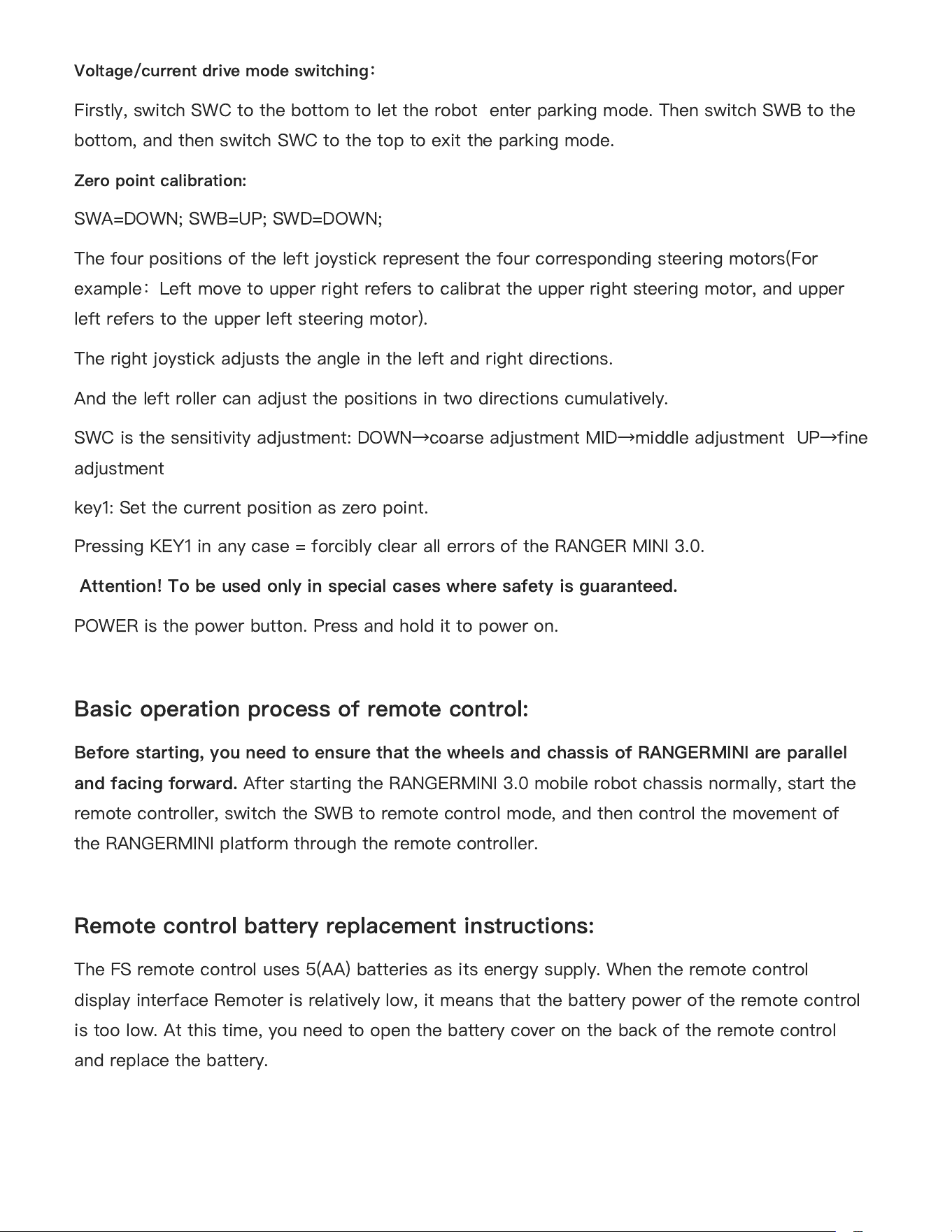
Figure 2.4 Introductionof the remote control
As shown in the figure above, the functions of the buttons are defined as follows: SWB is the
control mode, switch to the top is the command control mode, dialed to the middle or down is
the remote control mode; SWA is the light control switch, dialed to the bottom is to turn off the
light (need SWB first enters the remote control mode); SWC controls the parking mode.When
SWC is turned to the bottom, it is the parking mode, and the four-wheel four-steering is X-
shaped at this time Locking.
SWD is the switch for Motion mode:
MovingSWD to the top is
①
front and rear Ackerman mode(the left joystick controls the speed,
and the right joystick controls the steeringangle)+
②
spin mode (the left joystick does not
move, theright joystick controls the spindirection)
MovingSWD to the bottom is the tilt motion mode: the left joystick controls the speed, and the
right joystick controls the steeringangle (the maximum angle is 90°, which makesthe RANGER
MINI 3.0 move laterally);
13
Voltage/current drive mode switching
:
Firstly, switch SWC to the bottom to let the robot enter parking mode. Then switch SWB to the
bottom, and then switch SWC to the top to exit the parking mode.
Zero point calibration:
SWA=DOWN; SWB=UP; SWD=DOWN;
The four positions of the left joystick represent the four corresponding steering motors(For
example
:
Left move to upper right refers to calibrat the upper right steering motor, and upper
left refers to the upper left steering motor).
The right joystick adjusts the angle in the left and right directions.
And the left roller can adjust the positions in two directions cumulatively.
SWC is the sensitivity adjustment: DOWN
→
coarse adjustment MID
→
middle adjustment UP
→
fine
adjustment
key1: Set the current position as zero point.
PressingKEY1 in any case = forcibly clear all errors of the RANGER MINI 3.0.
Attention! To be used only in special cases where safety is guaranteed.
POWER is the power button. Press and hold itto power on.
Basic operation process of remote control:
Before starting, you need to ensure that the wheels and chassis of RANGERMINI are parallel
and facing forward.
After starting the RANGERMINI 3.0 mobile robot chassis normally, start the
remote controller, switch the SWB to remote control mode, and then control the movement of
the RANGERMINI platform through the remote controller.
Remote control battery replacement instructions:
The FS remote control uses 5(AA) batteries as its energy supply. When the remote control
display interface Remoter is relatively low, it means that the battery power of the remote control
is too low. At this time, you need to open the battery cover on the back of the remote control
and replace the battery.
14
This part mainly introduces the basic operation and usageof the RANGER MINI 3.0, and how to
carry out secondary development through the external CAN interface and the CAN bus protocol.
Check
Check the RANGER MINI 3.0status
Check whether there is any obvious abnormality in the RANGERMINI 3.0; if so, please contact
after-sales support;
When using it for the first time, check whether the e-stop switch(Q2)in the rear electrical panel
is pressed, if pressed, please release it.
PAY ATTENTION
:
After the emergency stop button is released, you need to manually press key1
to clear the emergency stop error in remote control mode. In command mode, you need to clear
the emergency stop error through the clear error command.
Power on and off
The Q3 button on the tail is a switch button. When pressed, the power is turned on and the robot
is powered on.
Charge
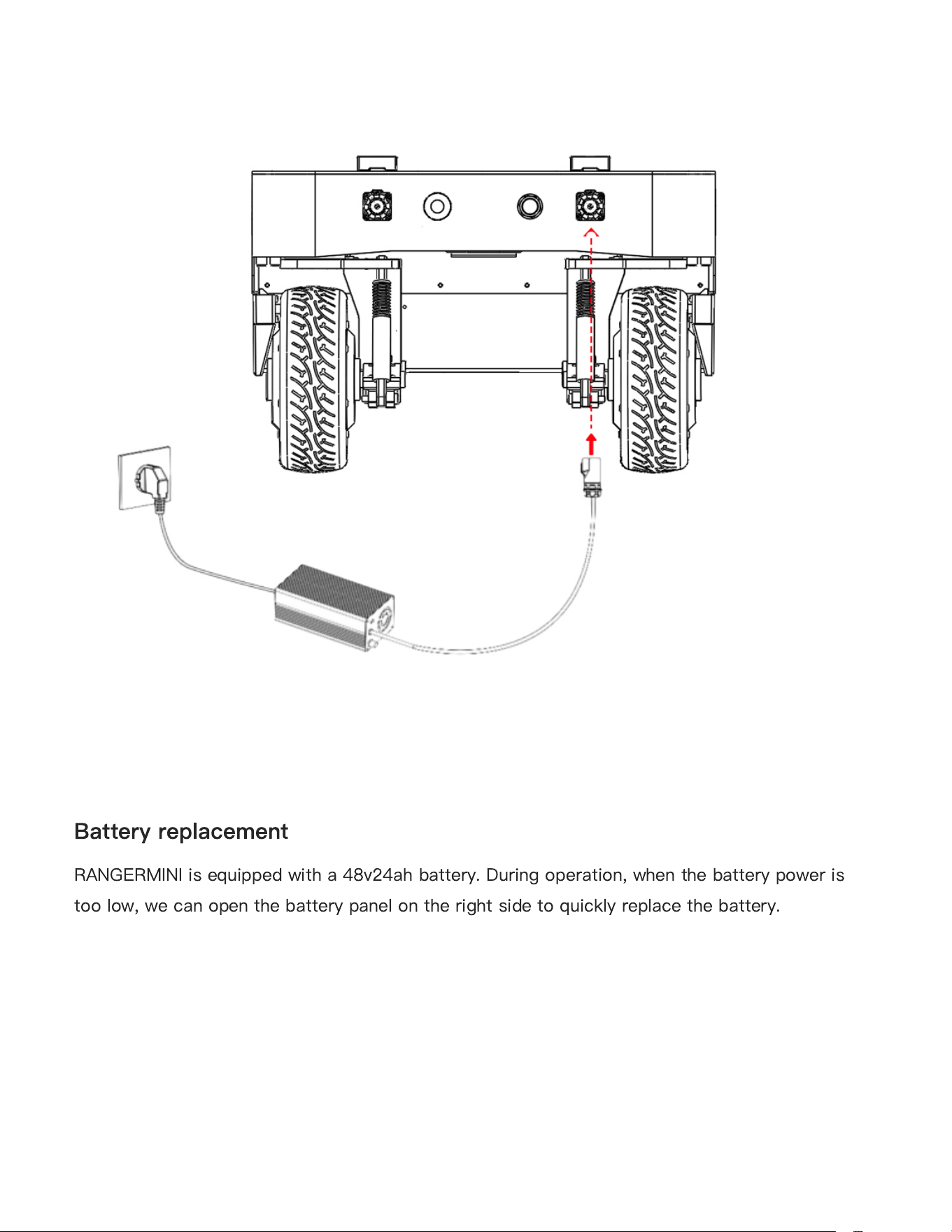
Check the battery voltage, the normal voltage range is 45-54V, if the front light flashes, it means
the battery voltage is too low, please charge it in time. This product is equipped with a 10A
charger by default. Insert the plug of the charger into the Q4 charging socket on the back of the
chassis, connect the charger to the power supply, and turn on the switch on the charger to enter
the charging state.
3 Usageand Development
3.1Operation
15
Battery replacement
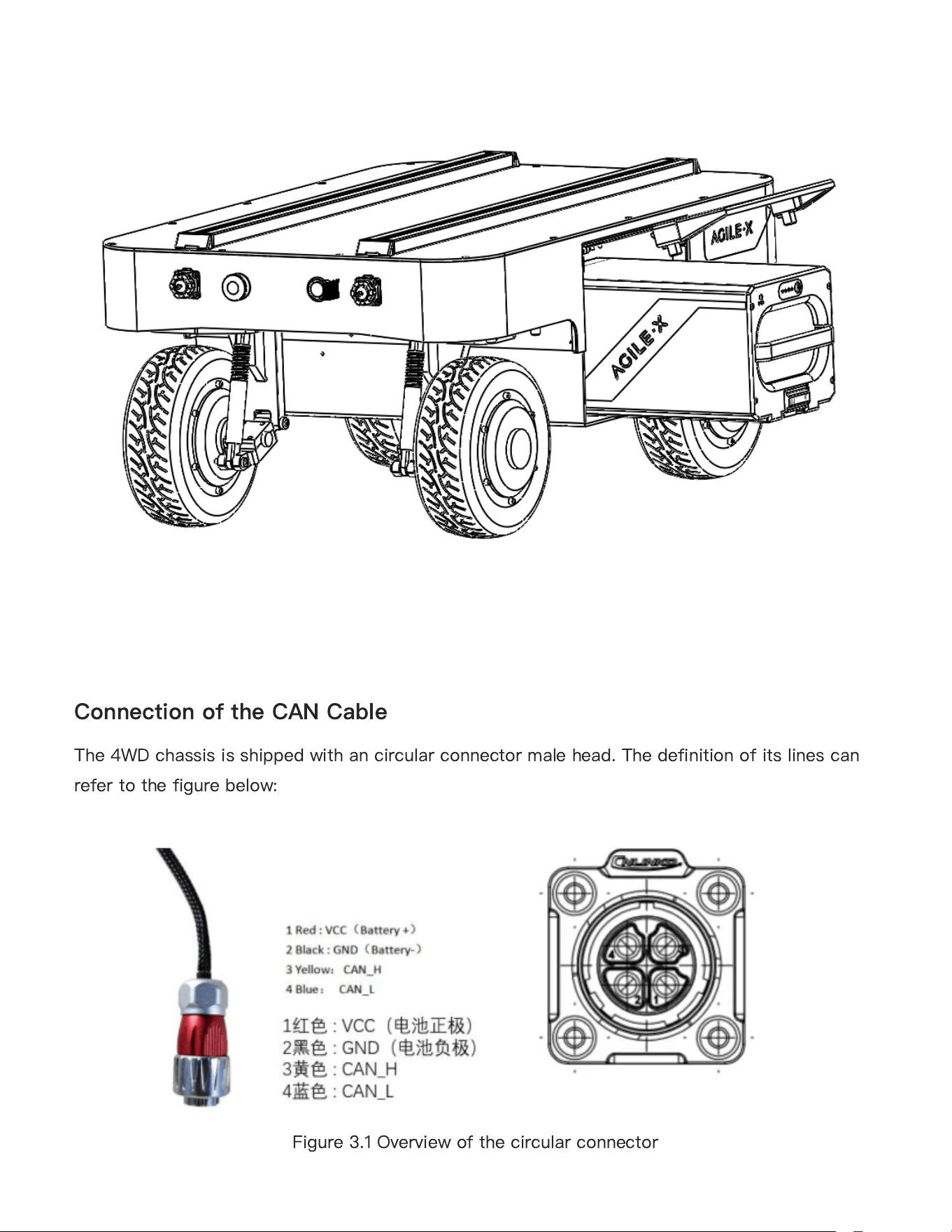
RANGERMINI is equipped with a 48v24ah battery. During operation, when the battery power is
too low, we can open the battery panel on the right side to quickly replace the battery.
16
Connection of the CAN Cable
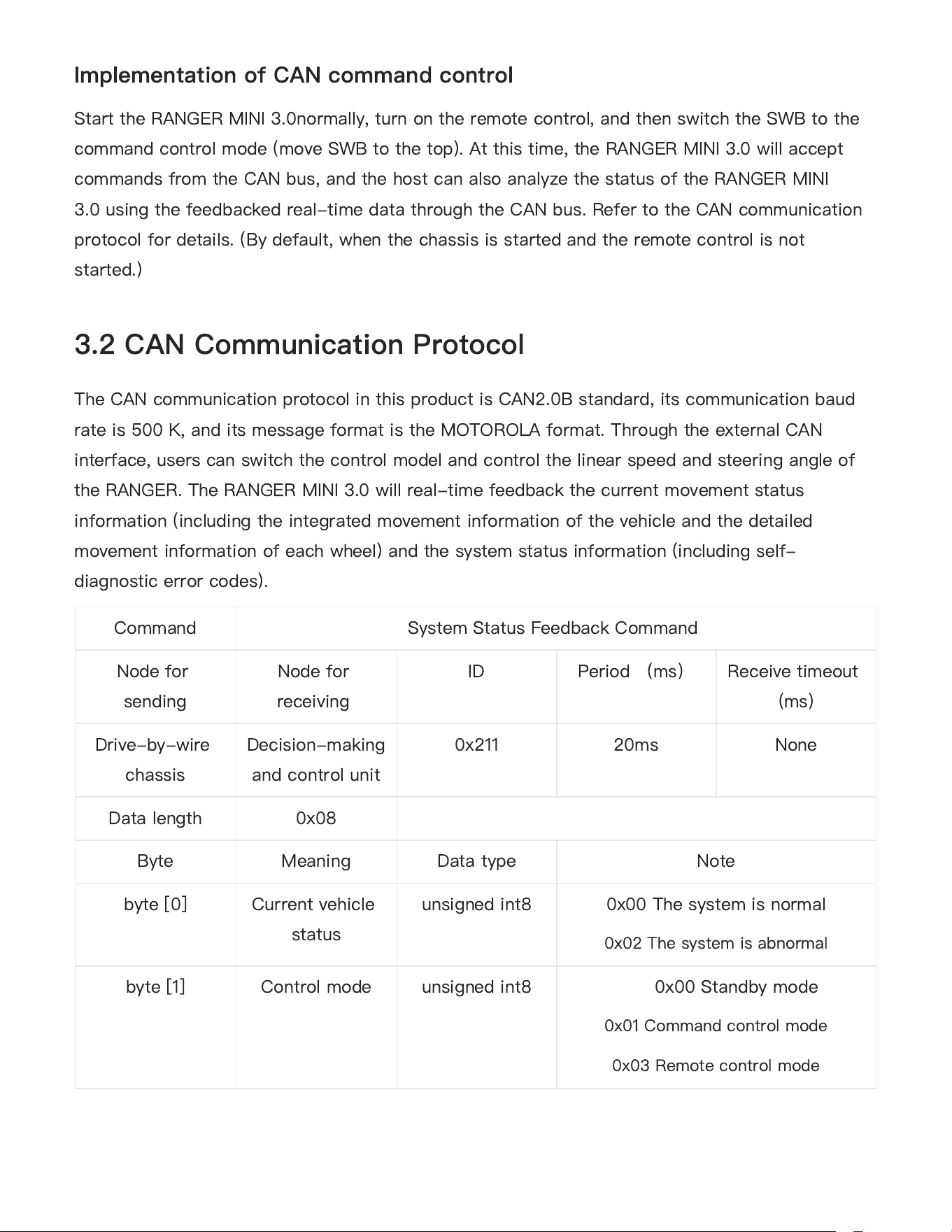
The 4WDchassis is shipped with ancircular connectormale head. The definition of its linescan
refer to the figure below:
Figure 3.1 Overview of the circular connector
17
Implementation of CAN command control
Start the RANGER MINI 3.0normally, turn on the remote control, and then switch the SWB to the
command control mode (move SWB to the top). At this time, the RANGER MINI 3.0will accept
commands from the CAN bus, and the host can also analyze the status of the RANGER MINI
3.0using the feedbackedreal-time data through the CAN bus. Refer to the CAN communication
protocol for details. (By default, when the chassis is started and the remote control is not
started.)
The CAN communication protocol in this product isCAN2.0B standard, its communication baud
rate is 500 K, and its message format is the MOTOROLA format. Through the external CAN
interface, users can switch the control model and control the linear speed and steering angle of
the RANGER. The RANGER MINI 3.0 will real-time feedback the current movement status
information (including the integrated movement information of the vehicle and the detailed
movement information of each wheel) and the system status information (including self-
diagnostic error codes).
3.2 CAN Communication Protocol
Command System Status Feedback Command
Node for
sending
Node for
receiving
ID Period
(
ms
)
Receive timeout
(ms)
Drive-by-wire
chassis
Decision-making
and control unit
0x211 20ms None
Data length 0x08
Byte Meaning Data type Note
byte [0] Current vehicle
status
unsigned int8 0x00 The system is normal
0x02 The system is abnormal
byte [1] Control mode unsigned int8 0x00 Standby mode
0x01 Command control mode
0x03 Remote control mode
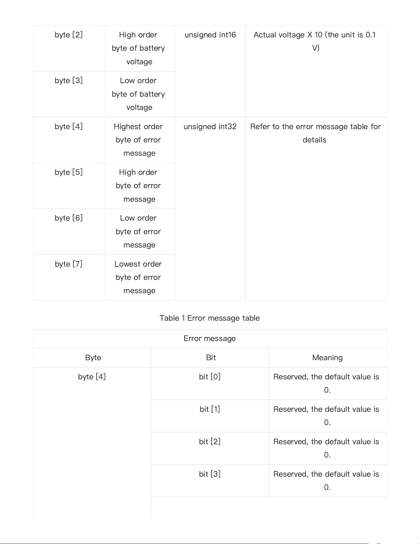
18
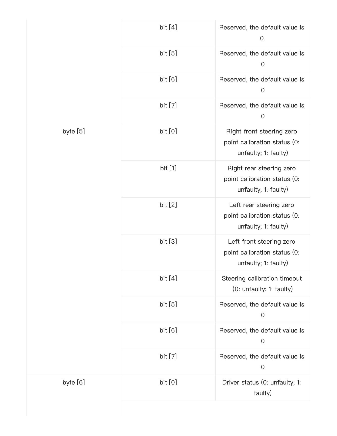
Table 1 Error message table
byte [2] High order
byteof battery
voltage
unsigned int16 Actual voltage X 10 (the unit is 0.1
V)
byte [3] Low order
byteof battery
voltage
byte [4] Highest order
byteof error
message
unsigned int32 Refer to the error message table for
details
byte [5] High order
byteof error
message
byte [6] Low order
byteof error
message
byte [7] Lowest order
byteof error
message
Error message
Byte Bit Meaning
byte [4] bit [0] Reserved, the default value is
0.
bit [1] Reserved, the default value is
0.
bit [2] Reserved, the default value is
0.
bit [3] Reserved, the default value is
0.
19
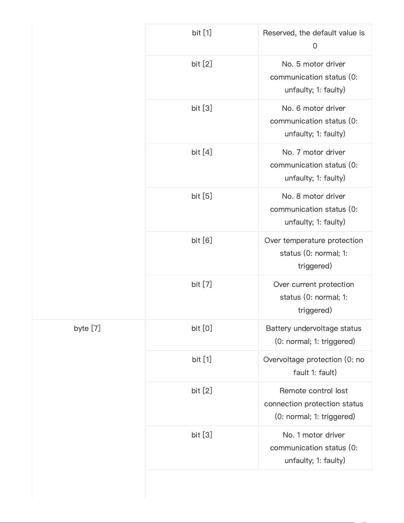
bit [4] Reserved, the default value is
0.
bit [5] Reserved, the default value is
0
bit [6] Reserved, the default value is
0
bit [7] Reserved, the default value is
0
byte [5] bit [0] Right front steering zero
pointcalibration status (0:
unfaulty; 1: faulty)
bit [1] Right rear steering zero
pointcalibration status (0:
unfaulty; 1: faulty)
bit [2] Left rearsteering zero
pointcalibration status (0:
unfaulty; 1: faulty)
bit [3] Left front steering zero
pointcalibration status (0:
unfaulty; 1: faulty)
bit [4] Steering calibration timeout
(0: unfaulty; 1: faulty)
bit [5] Reserved, the default value is
0
bit [6] Reserved, the default value is
0
bit [7] Reserved, the default value is
0
byte [6] bit [0] Driverstatus (0: unfaulty; 1:
faulty)
20
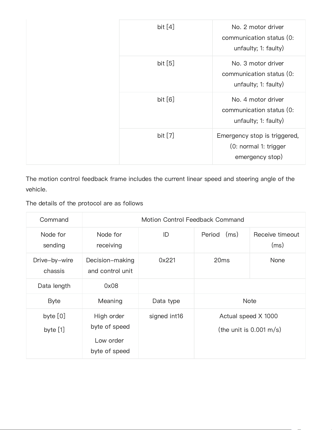
bit [1] Reserved, the default value is
0
bit [2] No. 5 motor driver
communication status (0:
unfaulty; 1: faulty)
bit [3] No. 6 motor driver
communication status (0:
unfaulty; 1: faulty)
bit [4] No. 7 motor driver
communication status (0:
unfaulty; 1: faulty)
bit [5] No. 8 motor driver
communication status (0:
unfaulty; 1: faulty)
bit [6] Over temperature protection
status (0: normal; 1:
triggered)
bit [7] Over current protection
status (0: normal; 1:
triggered)
byte [7] bit [0] Battery undervoltage status
(0: normal; 1: triggered)
bit [1] Overvoltage protection (0: no
fault 1: fault)
bit [2] Remote control lost
connection protection status
(0: normal; 1: triggered)
bit [3] No. 1 motor driver
communication status (0:
unfaulty; 1: faulty)
21
The motion control feedback frame includes thecurrentlinear speed and steering angle of the
vehicle.
The details of the protocol are as follows
bit [4] No. 2 motor driver
communication status (0:
unfaulty; 1: faulty)
bit [5] No. 3 motor driver
communication status (0:
unfaulty; 1: faulty)
bit [6] No. 4 motor driver
communication status (0:
unfaulty; 1: faulty)
bit [7] Emergency stop is triggered,
(0: normal 1: trigger
emergency stop)
Command Motion Control Feedback Command
Node for
sending
Node for
receiving
ID Period
(
ms
)
Receive timeout
(ms)
Drive-by-wire
chassis
Decision-making
and control unit
0x221 20ms None
Data length 0x08
Byte Meaning Data type Note
byte [0]
byte [1]
High order
byteof speed
Low order
byteof speed
signed int16 Actual speed X 1000
(the unit is 0.001 m/s)
22
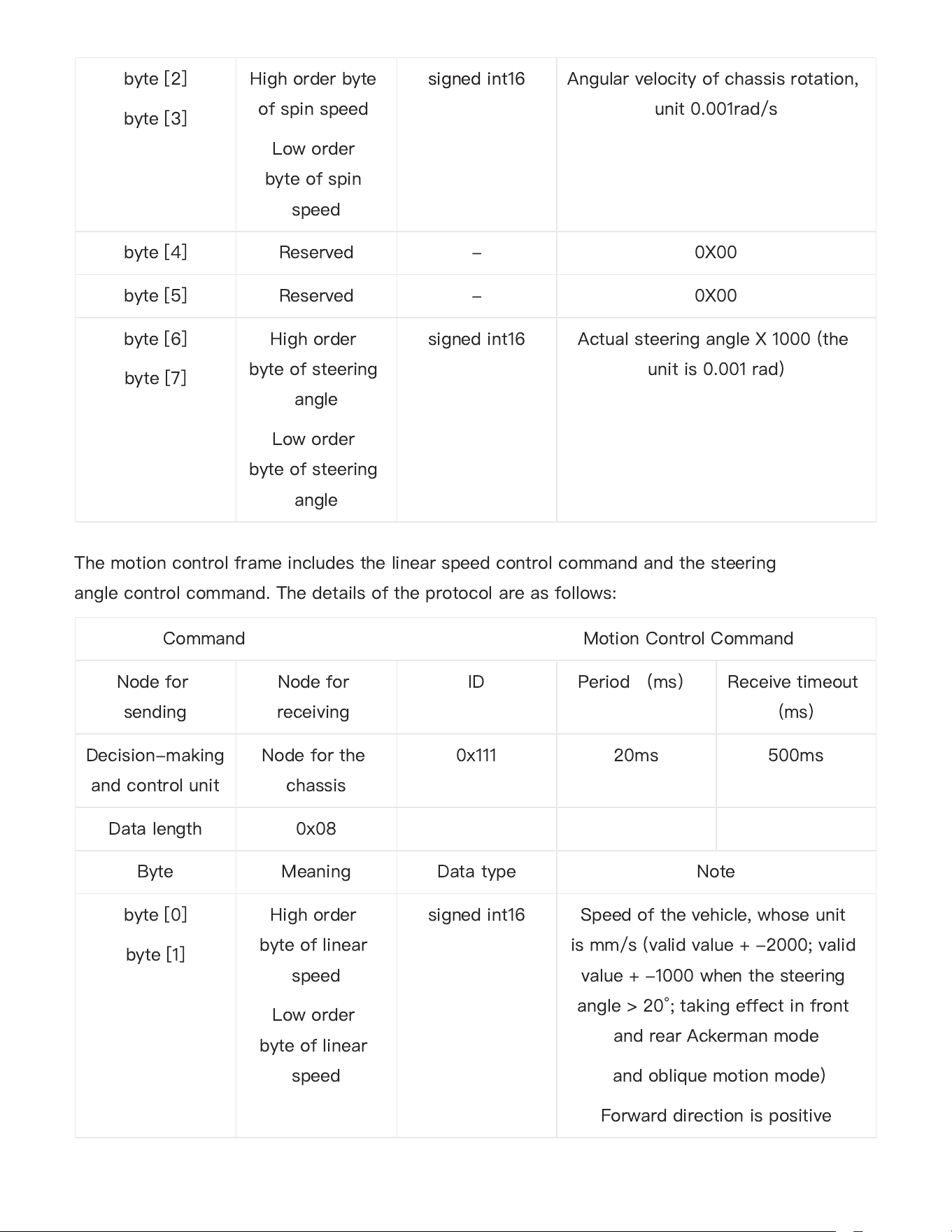
The motion control frame includes the linear speed control command and the steering
anglecontrol command. The details of the protocol are as follows:
byte [2]
byte [3]
High order byte
of spin speed
Low order
byteof spin
speed
signed int16 Angular velocity of chassis rotation,
unit 0.001rad/s
byte [4] Reserved - 0X00
byte [5] Reserved - 0X00
byte [6]
byte [7]
High order
byteof steering
angle
Low order
byteof steering
angle
signed int16 Actual steering angleX 1000 (the
unit is 0.001 rad)
Command Motion Control Command
Node for
sending
Node for
receiving
ID Period
(
ms
)
Receive timeout
(ms)
Decision-making
and control unit
Node for the
chassis
0x111 20ms 500ms
Data length 0x08
Byte Meaning Data type Note
byte [0]
byte [1]
High order
byteof linear
speed
Low order
byteof linear
speed
signed int16 Speed of the vehicle, whose unit
ismm/s (valid value + -2000; valid
value + -1000 when the steering
angle > 20°; taking effect in front
and rear Ackerman mode
and oblique motion mode)
Forward direction is positive
23
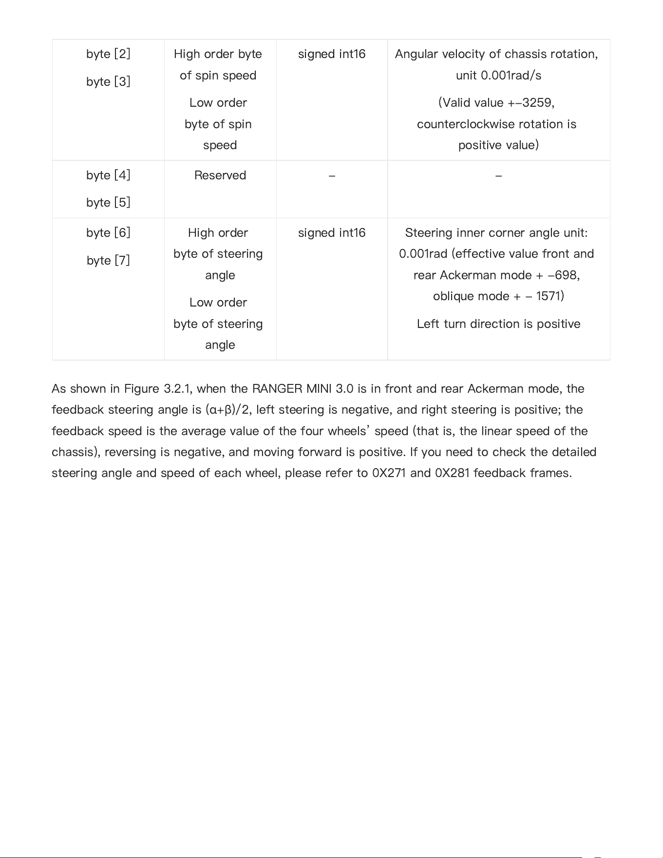
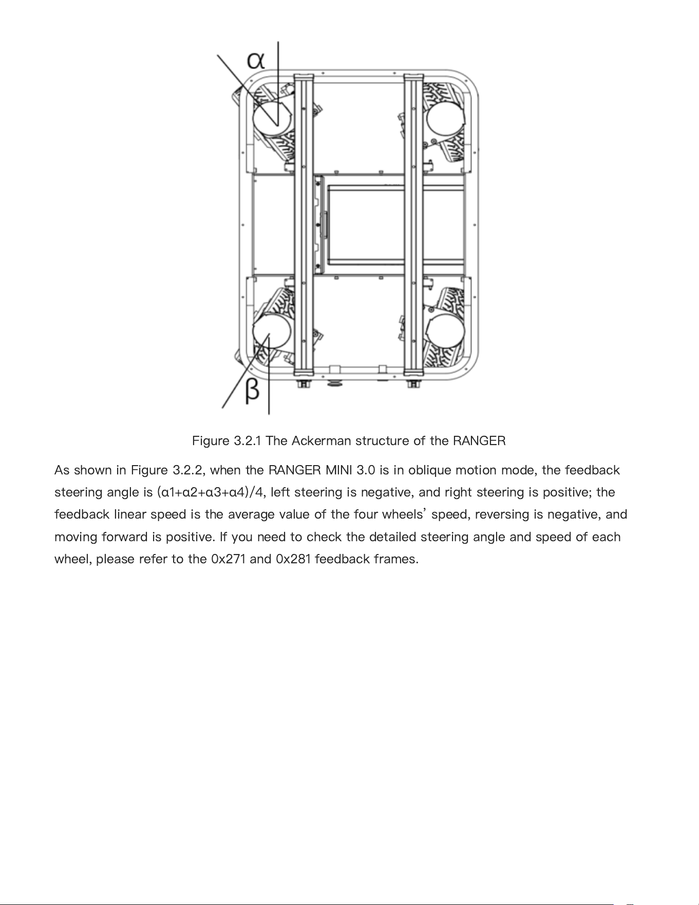
As shown in Figure 3.2.1, when the RANGER MINI 3.0is in front and rear Ackerman mode, the
feedback steering angle is (
α
+
β
)/2, left steering is negative, and right steering ispositive; the
feedback speed is the average value of the four wheels
’
speed(that is, the linear speed of the
chassis), reversing is negative, and moving forwardis positive. If you need to check the detailed
steering angle and speed of each wheel, please refer to 0X271 and 0X281 feedback frames.
byte [2]
byte [3]
High order byte
of spin speed
Low order
byteof spin
speed
signed int16 Angular velocity of chassis rotation,
unit 0.001rad/s
(Valid value +-3259,
counterclockwise rotation is
positive value)
byte [4]
byte [5]
Reserved - -
byte [6]
byte [7]
High order
byteof steering
angle
Low order
byteof steering
angle
signed int16 Steering inner corner angle unit:
0.001rad (effective value front and
rear Ackerman mode + -698,
oblique mode + - 1571)
Left turn direction is positive
24
Figure 3.2.1 The Ackerman structure of the RANGER
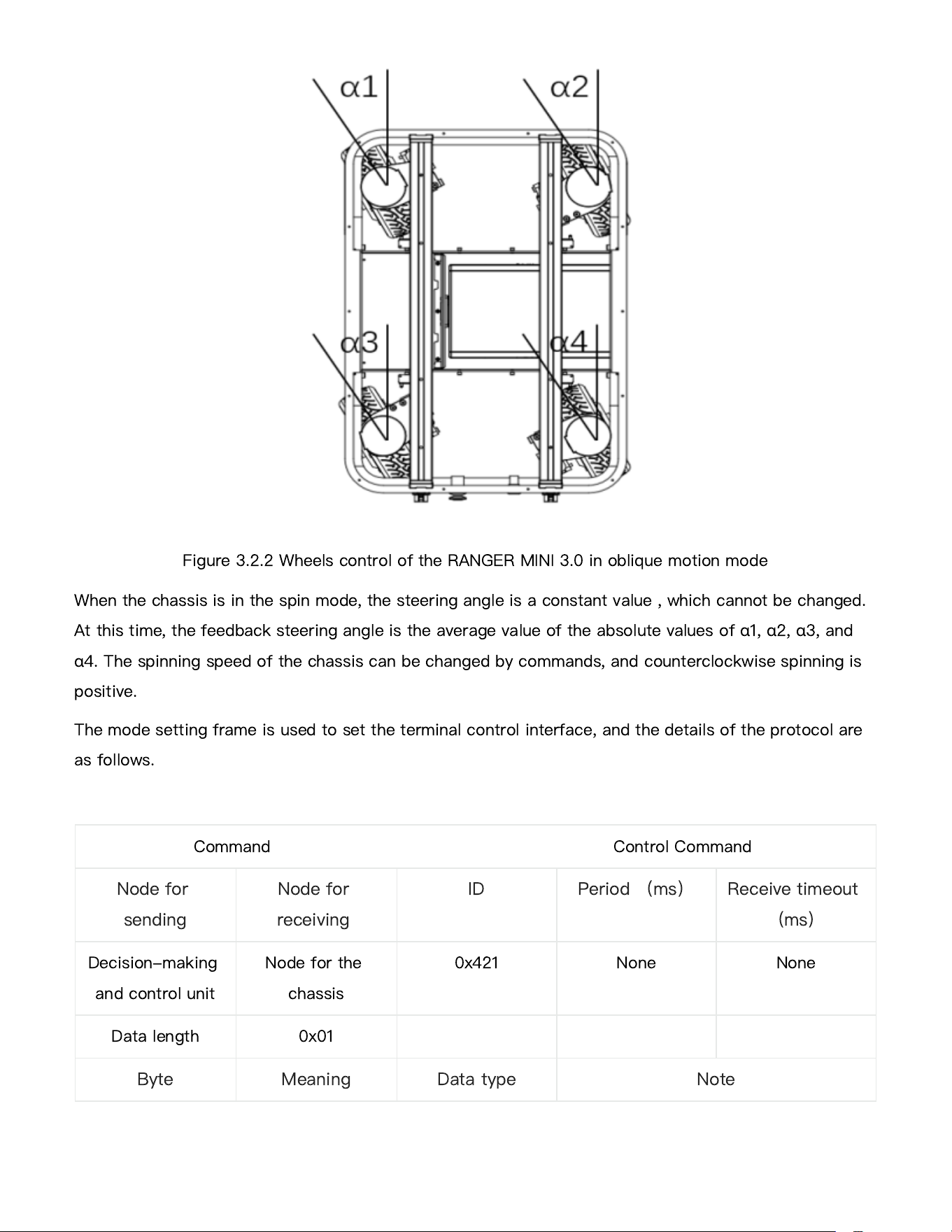
As shown in Figure 3.2.2, when the RANGER MINI 3.0is in oblique motion mode, the feedback
steering angle is (
α
1+
α
2+
α
3+
α
4)/4, left steering is negative, and right steering ispositive; the
feedback linear speed is the average value of the four wheels
’
speed, reversing is negative, and
moving forwardis positive. If you need to check the detailed steering angle and speed of each
wheel, please refer to the 0x271 and 0x281 feedback frames.
25
Figure 3.2.2 Wheels control of the RANGER MINI 3.0in oblique motionmode
When the chassis is in the spin mode, the steering angle is a constant value , which cannot be changed.
At this time, the feedback steering angle is the average value of the absolute values of
α
1,
α
2,
α
3, and
α
4. The spinning speed of the chassis can be changedby commands, and counterclockwise spinningis
positive.
The mode setting frame is used to set the terminal control interface, and the details of the protocol are
as follows.
Command ControlCommand
Node for
sending
Node for
receiving
ID Period
(
ms
)
Receive timeout
(ms)
Decision-making
and control unit
Node for the
chassis
0x421
None
None
Data length
0x01
Byte Meaning Data type Note
26
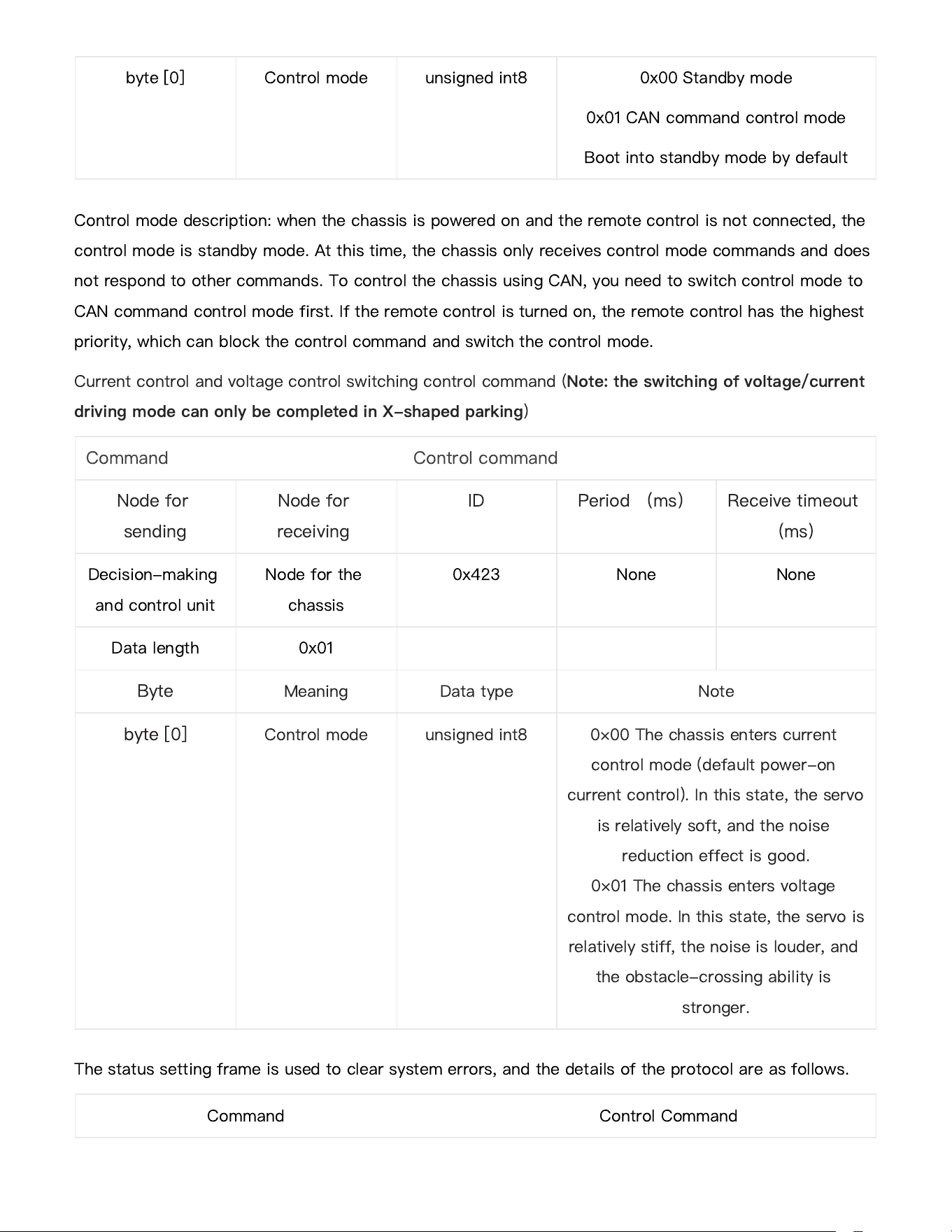
Control mode description: when the chassis is powered on and the remote control is not connected, the
control mode is standby mode. At this time, the chassis only receives control mode commands and does
not respond to other commands. To control the chassis using CAN, you need to switch control mode to
CAN command control mode first. If the remote control is turned on, the remote control has the highest
priority, which can block the control command and switch the control mode.
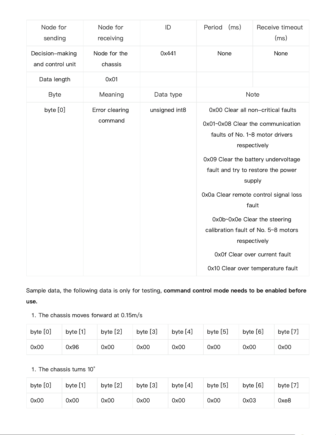
Current control and voltage control switching control command (
Note: the switching of voltage/current
driving mode can only be completed in X-shaped parking
)
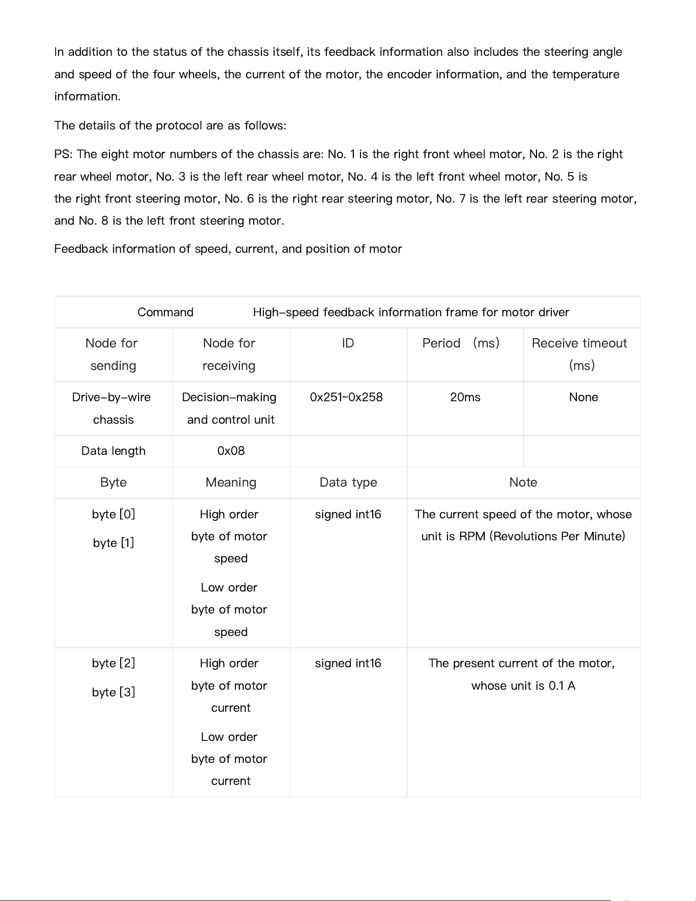
The status setting frame is used to clear system errors, and the details of the protocol are as follows.
byte [0]
Control mode
unsigned int8
0x00 Standby mode
0x01 CANcommand control mode
Boot into standby mode by default
Command Control command
Node for
sending
Node for
receiving
ID Period
(
ms
)
Receive timeout
(ms)
Decision-making
and control unit
Node for the
chassis
0x423
None
None
Data length
0x01
Byte
Meaning
Data type
Note
byte[0]
Control mode
unsigned int8
0×00 The chassis enters current
control mode (default power-on
current control). In this state, the servo
is relatively soft, and the noise
reduction effect is good.
0×01 The chassis enters voltage
control mode. In this state, the servo is
relatively stiff, the noise is louder, and
the obstacle-crossing ability is
stronger.
Command Control Command
27
Sample data, the following data is only for testing,
command control mode needs to be enabled before
use.
1.
The chassis moves forward at 0.15m/s
1.
The chassis turns 10°
Node for
sending
Node for
receiving
ID Period
(
ms
)
Receive timeout
(ms)
Decision-making
and control unit
Node for the
chassis
0x441
None
None
Data length
0x01
Byte Meaning Data type Note
byte [0]
Error clearing
command
unsigned int8
0x00 Clear all non-critical faults
0x01~0x08
Clear the communication
faults of No. 1~8 motor drivers
respectively
0x09 Clear the battery undervoltage
fault and try to restore the power
supply
0x0a Clear remote control signal loss
fault
0x0b~0x0e Clear the steering
calibration fault of No. 5~8 motors
respectively
0x0f Clear over current fault
0x10 Clear over temperature fault
byte [0]
byte [1]
byte [2]
byte [3]
byte [4]
byte [5]
byte [6]
byte [7]
0x00
0x96
0x00
0x00
0x00
0x00
0x00
0x00
byte [0]
byte [1]
byte [2]
byte [3]
byte [4]
byte [5]
byte [6]
byte [7]
0x00
0x00
0x00
0x00
0x00
0x00
0x03
0xe8
28
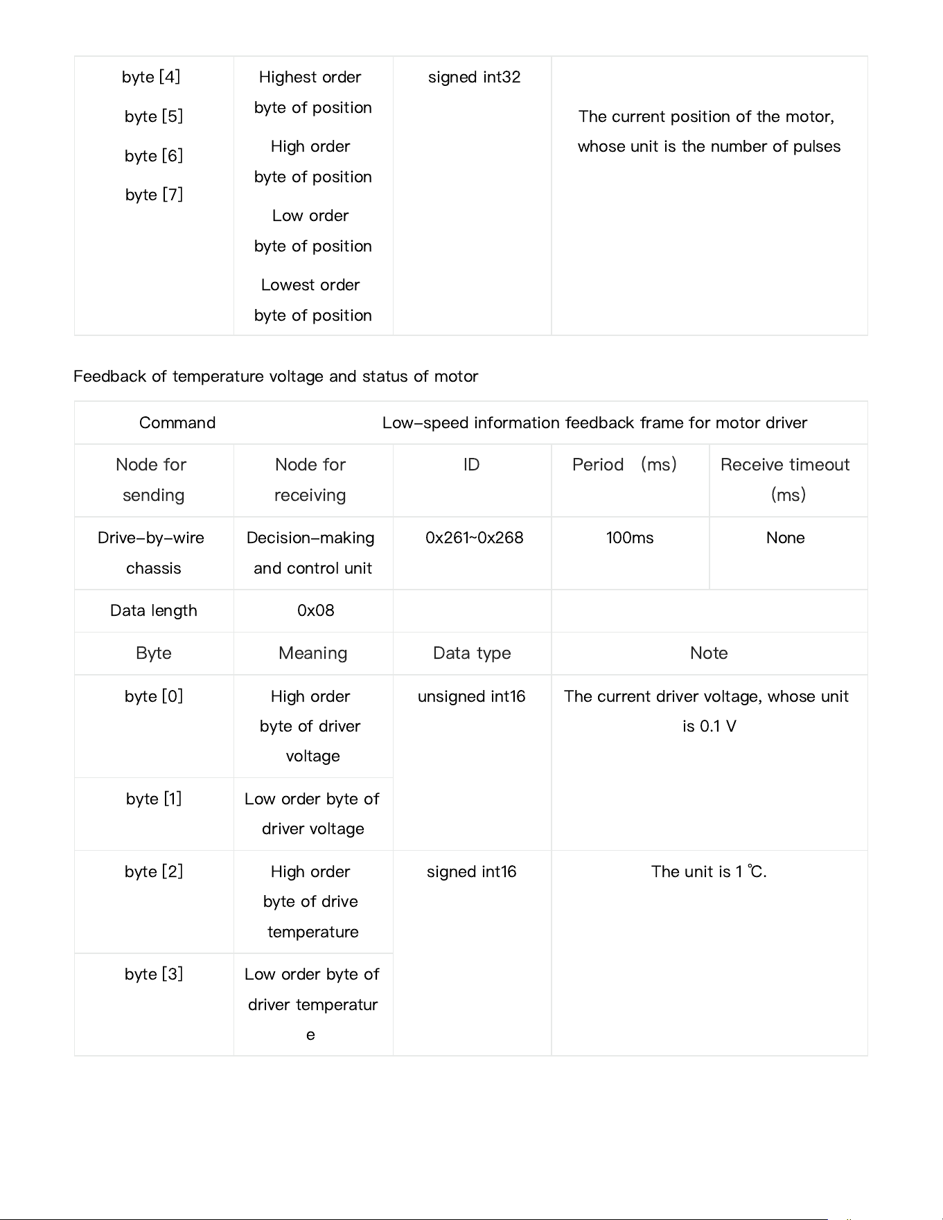
In addition to the status of the chassis itself, its feedback information also includes the steering angle
and speed of the four wheels, the current of the motor, the encoder information, and the temperature
information.
The details of the protocol are as follows:
PS: The eight motor numbers of the chassis are: No. 1 is theright front wheel motor, No. 2 is theright
rear wheel motor, No. 3 is theleft rear wheel motor, No. 4 is the left front wheel motor, No. 5 is
theright front steering motor, No. 6 is theright rear steering motor, No. 7 is the left rear steering motor,
andNo. 8 is the left front steering motor.
Feedback information of speed, current, andposition of motor
Command High-speed feedback information frame for motor driver
Node for
sending
Node for
receiving
ID Period
(
ms
)
Receive timeout
(ms)
Drive-by-wire
chassis
Decision-making
and control unit
0x251~0x258
20ms
None
Data length
0x08
Byte Meaning Data type Note
byte [0]
byte [1]
High order
byteofmotor
speed
Low order
byteofmotor
speed
signed int16
The current speed of the motor, whose
unit is RPM (Revolutions Per Minute)
byte [2]
byte [3]
High order
byteofmotor
current
Low order
byteofmotor
current
signed int16
The present current of the motor,
whose unit is 0.1 A
29
Feedback of temperature voltage and status of motor
byte [4]
byte [5]
byte [6]
byte [7]
Highest order
byteofposition
High order
byteofposition
Low order
byteofposition
Lowest order
byteofposition
signed int32
The current position of the motor,
whose unit is the number of pulses
Command Low-speed information feedback frame for motor driver
Node for
sending
Node for
receiving
ID Period
(
ms
)
Receive timeout
(ms)
Drive-by-wire
chassis
Decision-making
and control unit
0x261~0x268
100ms
None
Data length
0x08
Byte Meaning Data type Note
byte [0]
High order
byteof driver
voltage
unsigned int16
The current driver voltage, whose unit
is 0.1 V
byte [1]
Low order byteof
driver voltage
byte [2]
High order
byteof drive
temperature
signed int16
The unit is 1
℃
.
byte [3]
Low order byteof
drivertemperatur
e
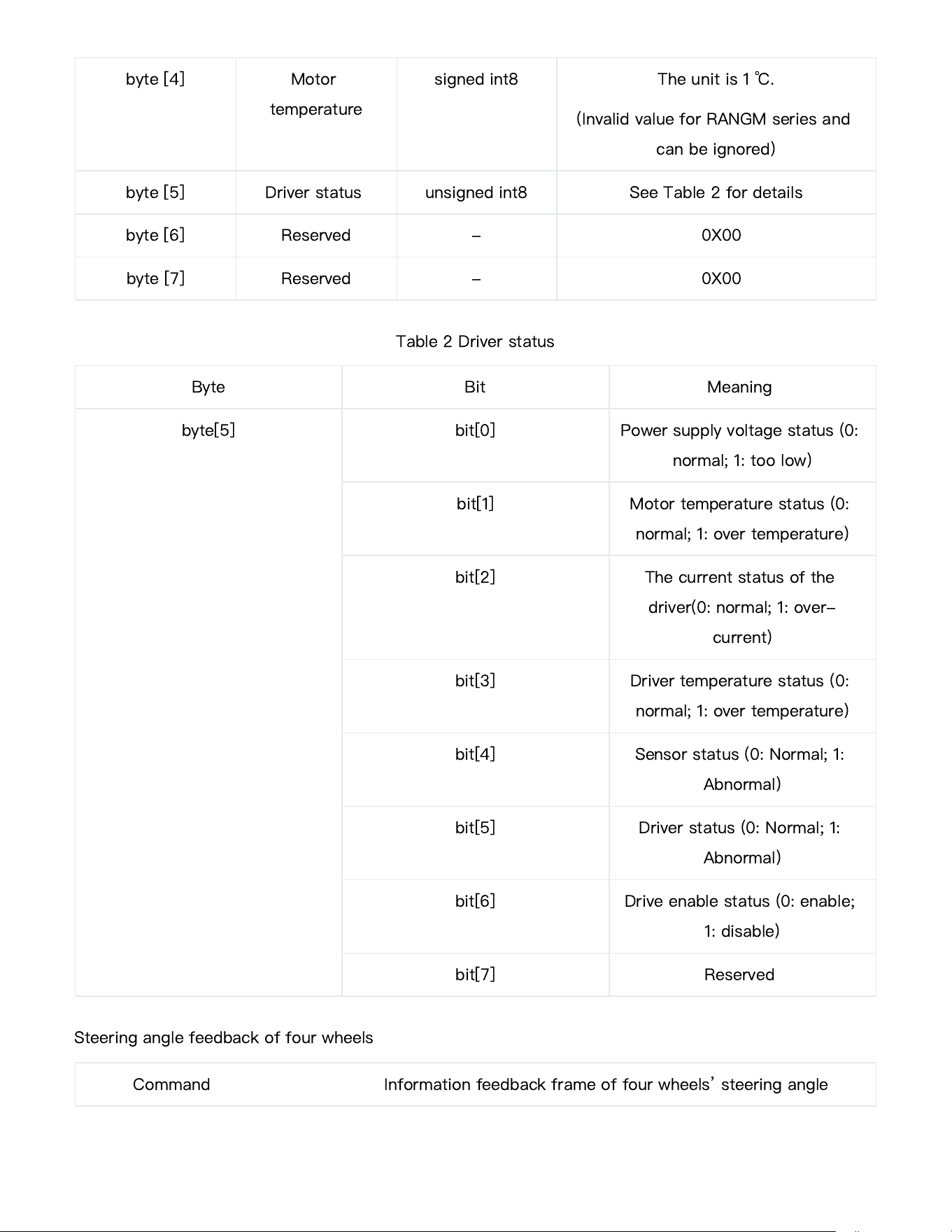
30
Table 2 Driver status
Steering angle feedback of four wheels
byte [4]
Motor
temperature
signed int8
The unit is 1
℃
.
(Invalid value for RANGM series and
can be ignored)
byte [5]
Driver status
unsigned int8
See Table 2 for details
byte [6]
Reserved
-
0X00
byte [7]
Reserved
-
0X00
Byte
Bit
Meaning
byte[5]
bit[0]
Power supply voltage status (0:
normal; 1: too low)
bit[1]
Motor temperature status (0:
normal; 1: over temperature)
bit[2]
The current statusof the
driver(0: normal; 1: over-
current)
bit[3]
Driver temperature status (0:
normal; 1: over temperature)
bit[4]
Sensor status (0: Normal; 1:
Abnormal)
bit[5]
Driver status (0: Normal; 1:
Abnormal)
bit[6]
Drive enable status (0: enable;
1: disable)
bit[7]
Reserved
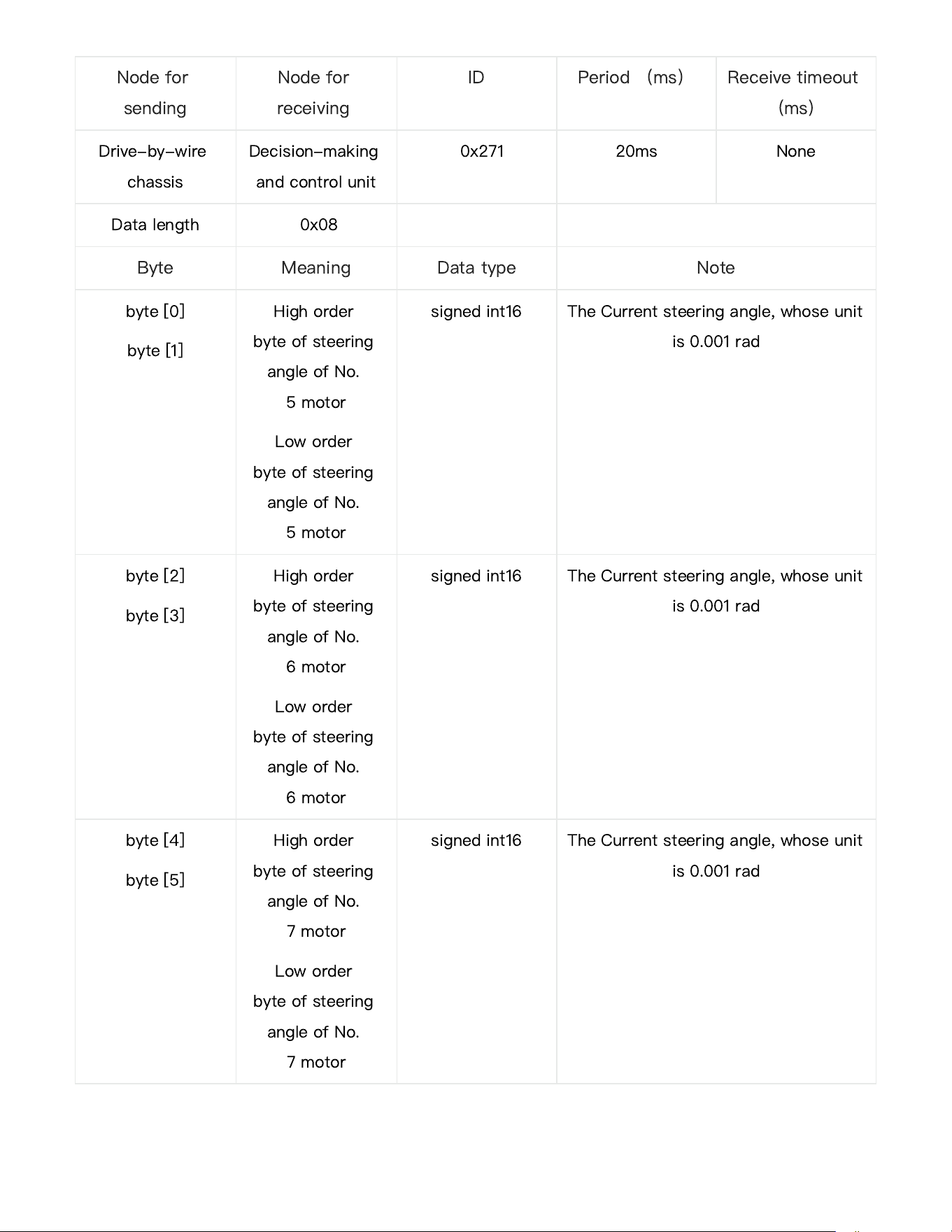
Command Information feedback frame of four wheels
’
steering angle
31
Node for
sending
Node for
receiving
ID Period
(
ms
)
Receive timeout
(ms)
Drive-by-wire
chassis
Decision-making
and control unit
0x271
20ms
None
Data length
0x08
Byte Meaning Data type Note
byte [0]
byte [1]
High order
byteofsteering
angle of No.
5motor
Loworder
byteofsteering
angle of No.
5motor
signed int16
The Current steering angle, whoseunit
is0.001 rad
byte [2]
byte [3]
High order
byteofsteering
angle of No.
6motor
Loworder
byteofsteering
angle of No.
6motor
signed int16
The Current steering angle, whoseunit
is0.001 rad
byte [4]
byte [5]
High order
byteofsteering
angle of No.
7motor
Loworder
byteofsteering
angle of No.
7motor
signed int16
The Current steering angle, whoseunit
is0.001 rad
32
Rotational speed feedback of four wheels
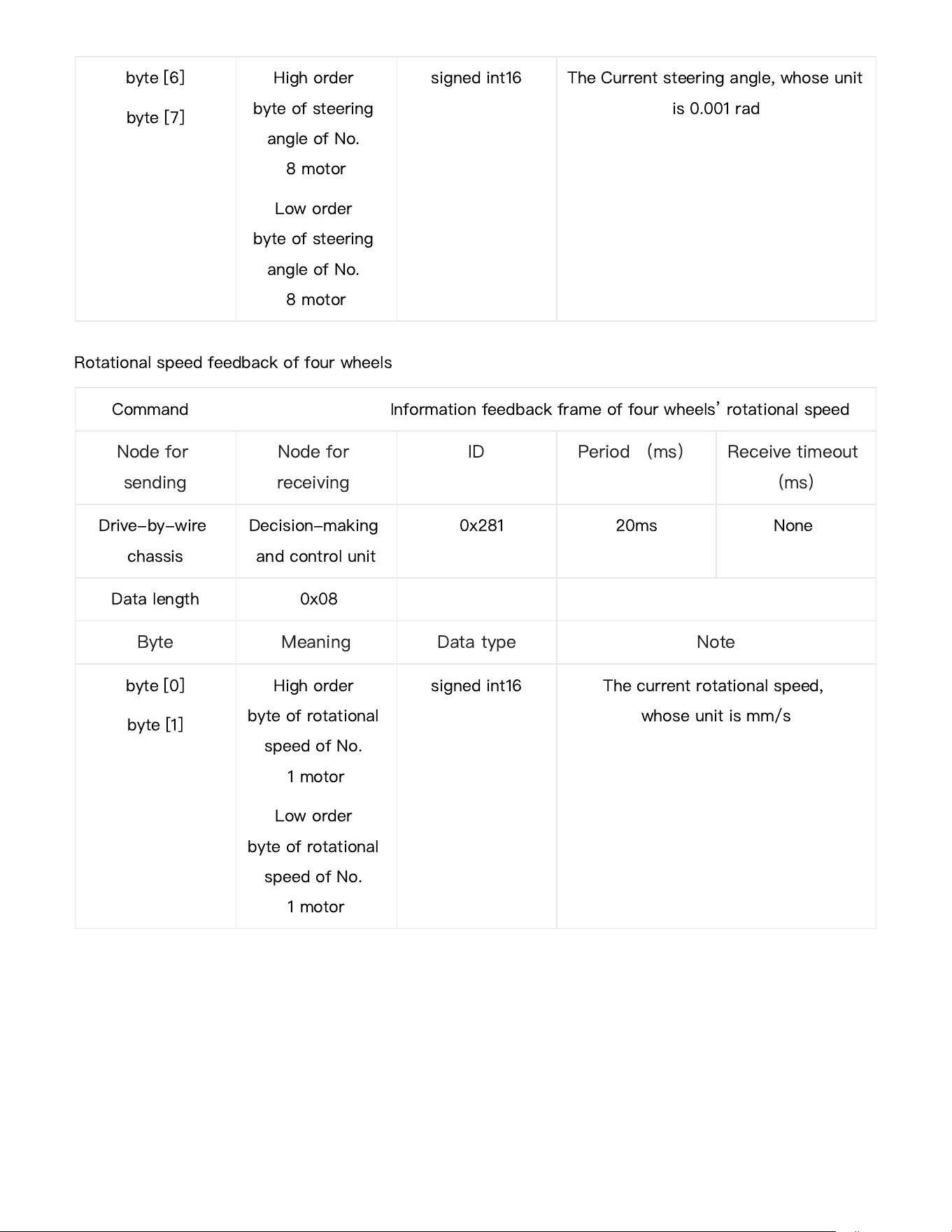
byte [6]
byte [7]
High order
byteofsteering
angle of No.
8motor
Loworder
byteofsteering
angle of No.
8motor
signed int16
The Current steering angle, whoseunit
is0.001 rad
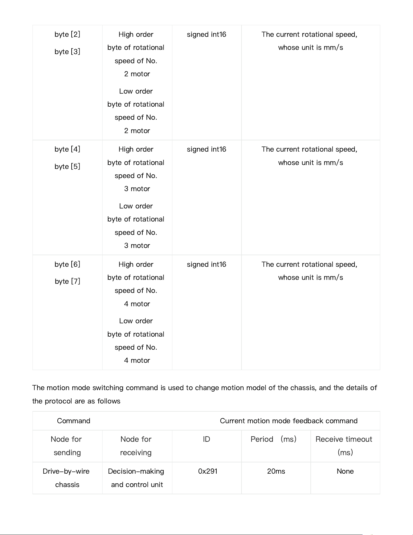
Command Information feedback frame of four wheels
’
rotational speed
Node for
sending
Node for
receiving
ID Period
(
ms
)
Receive timeout
(ms)
Drive-by-wire
chassis
Decision-making
and control unit
0x281
20ms
None
Data length
0x08
Byte Meaning Data type Note
byte [0]
byte [1]
High order
byteofrotational
speedof No.
1motor
Low order
byteofrotational
speedof No.
1motor
signed int16
The current rotational speed,
whoseunit is mm/s
33
The motion mode switching command is used to changemotion model of the chassis, and the details of
the protocol are as follows
byte [2]
byte [3]
High order
byteofrotational
speedof No.
2motor
Low order
byteofrotational
speedof No.
2motor
signed int16
The current rotational speed,
whoseunit is mm/s
byte [4]
byte [5]
High order
byteofrotational
speedof No.
3motor
Low order
byteofrotational
speedof No.
3motor
signed int16
The current rotational speed,
whoseunit is mm/s
byte [6]
byte [7]
High order
byteofrotational
speedof No.
4motor
Low order
byteofrotational
speedof No.
4motor
signed int16
The current rotational speed,
whoseunit is mm/s
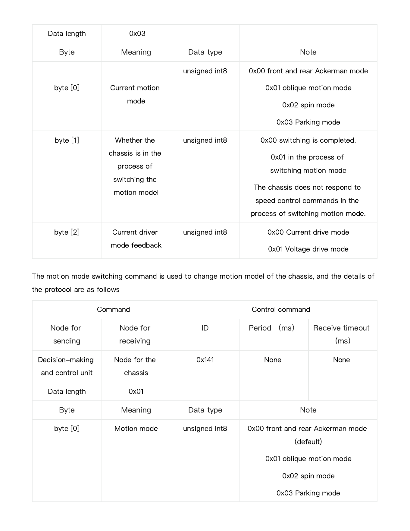
Command Current motionmode feedback command
Node for
sending
Node for
receiving
ID Period
(
ms
)
Receive timeout
(ms)
Drive-by-wire
chassis
Decision-making
and control unit
0x291
20ms
None
34
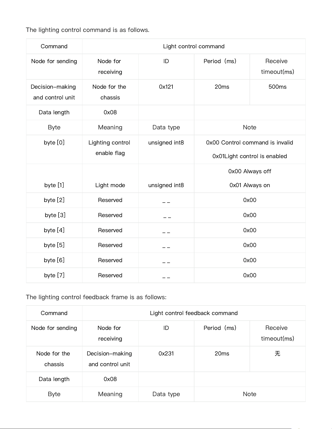
The motion mode switching command is used to changemotion model of the chassis, and the details of
the protocol are as follows
Data length
0x03
Byte Meaning Data type Note
byte [0]
Current motion
mode
unsigned int8
0x00 front and rear Ackerman mode
0x01oblique motion mode
0x02spin mode
0x03 Parking mode
byte [1]
Whether the
chassisis in the
process of
switching the
motion model
unsigned int8
0x00switching is completed.
0x01in theprocess of
switchingmotion mode
The chassis does not respond to
speed control commands in the
process of switchingmotion mode.
byte [2]
Current driver
mode feedback
unsigned int8
0x00 Current drive mode
0x01 Voltage drive mode
Command Control command
Node for
sending
Node for
receiving
ID Period
(
ms
)
Receive timeout
(ms)
Decision-making
and control unit
Node for the
chassis
0x141
None
None
Data length
0x01
Byte Meaning Data type Note
byte [0]
Motion mode
unsigned int8
0x00front and rear Ackerman mode
(default)
0x01oblique motion mode
0x02spin mode
0x03 Parking mode
35
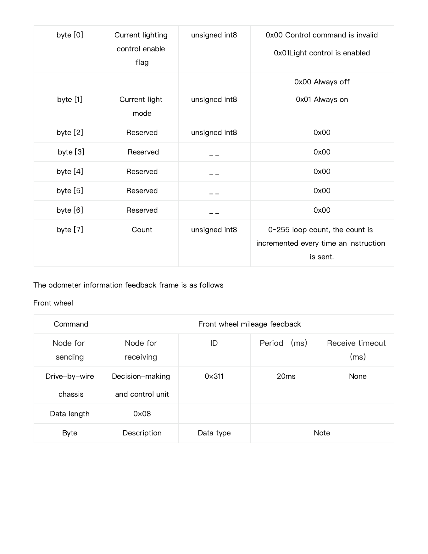
The lighting control command is as follows.
The lighting control feedback frame is as follows:
Command
Light control command
Node for sending
Node for
receiving
ID
Period
(
ms
)
Receive
timeout
(ms)
Decision-making
and control unit
Node for the
chassis
0x121
20ms
500ms
Data length
0x08
Byte Meaning Data type Note
byte [0]
Lighting control
enable flag
unsigned int8
0x00 Control command is invalid
0x01Light control is enabled
byte [1]
Light mode
unsigned int8
0x00 Always off
0x01 Always on
byte [2]
Reserved
_ _
0x00
byte [3]
Reserved
_ _
0x00
byte [4]
Reserved
_ _
0x00
byte [5]
Reserved
_ _
0x00
byte [6]
Reserved
_ _
0x00
byte [7]
Reserved
_ _
0x00
Command
Light control feedback command
Node for sending
Node for
receiving
ID
Period
(
ms
)
Receive
timeout
(ms)
Node for the
chassis
Decision-making
and control unit
0x231
20ms
⽆
Data length
0x08
Byte Meaning Data type Note
36
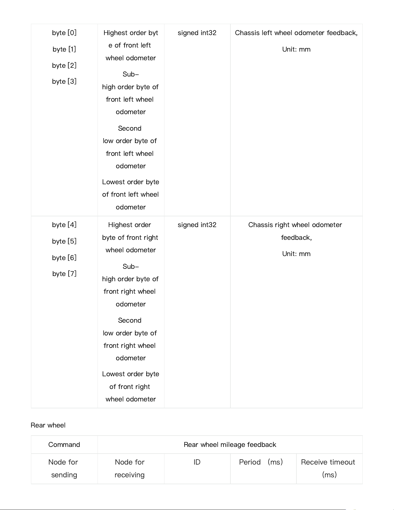
The odometer information feedback frame is as follows
Front wheel
byte [0]
Current lighting
control enable
flag
unsigned int8
0x00 Control command is invalid
0x01Light control is enabled
byte [1]
Current light
mode
unsigned int8
0x00 Always off
0x01 Always on
byte [2]
Reserved
unsigned int8
0x00
byte [3]
Reserved
_ _
0x00
byte [4]
Reserved
_ _
0x00
byte [5]
Reserved
_ _
0x00
byte [6]
Reserved
_ _
0x00
byte [7]
Count
unsigned int8
0~255 loop count, the count is
incremented every time an instruction
is sent.
Command
Front wheel mileage feedback
Node for
sending
Node for
receiving
ID Period
(
ms
)
Receive timeout
(ms)
Drive-by-wire
chassis
Decision-making
and control unit
0×311
20ms
None
Data length
0×08
Byte
Description
Data type
Note
37
Rear wheel
byte [0]
byte [1]
byte [2]
byte [3]
Highestorderbyt
e of front left
wheel odometer
Sub-
highorderbyte of
front left wheel
odometer
Second
loworderbyte of
front left wheel
odometer
Lowestorderbyte
of front left wheel
odometer
signed int32
Chassis left wheel odometer feedback,
Unit: mm
byte [4]
byte [5]
byte [6]
byte [7]
Highest order
byte of front right
wheel odometer
Sub-
highorderbyte of
front right wheel
odometer
Second
loworderbyte of
front right wheel
odometer
Lowestorderbyte
of front right
wheel odometer
signed int32
Chassis right wheel odometer
feedback,
Unit: mm
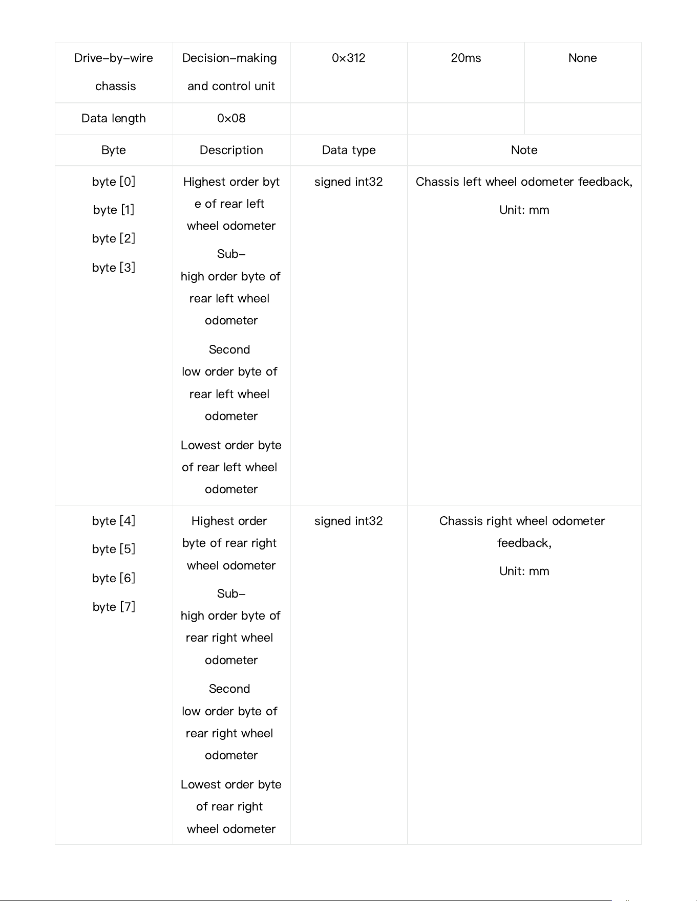
Command
Rear wheel mileage feedback
Node for
sending
Node for
receiving
ID Period
(
ms
)
Receive timeout
(ms)
38
Drive-by-wire
chassis
Decision-making
and control unit
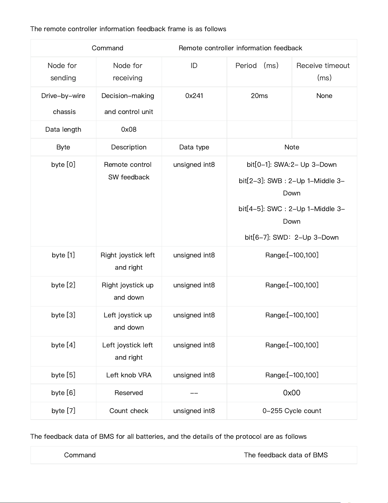
0×312
20ms
None
Data length
0×08
Byte
Description
Data type
Note
byte [0]
byte [1]
byte [2]
byte [3]
Highestorderbyt
e of rear left
wheel odometer
Sub-
highorderbyte of
rear left wheel
odometer
Second
loworderbyte of
rear left wheel
odometer
Lowestorderbyte
of rear left wheel
odometer
signed int32
Chassis left wheel odometer feedback,
Unit: mm
byte [4]
byte [5]
byte [6]
byte [7]
Highest order
byte of rear right
wheel odometer
Sub-
highorderbyte of
rear right wheel
odometer
Second
loworderbyte of
rear right wheel
odometer
Lowestorderbyte
of rear right
wheel odometer
signed int32
Chassis right wheel odometer
feedback,
Unit: mm
39
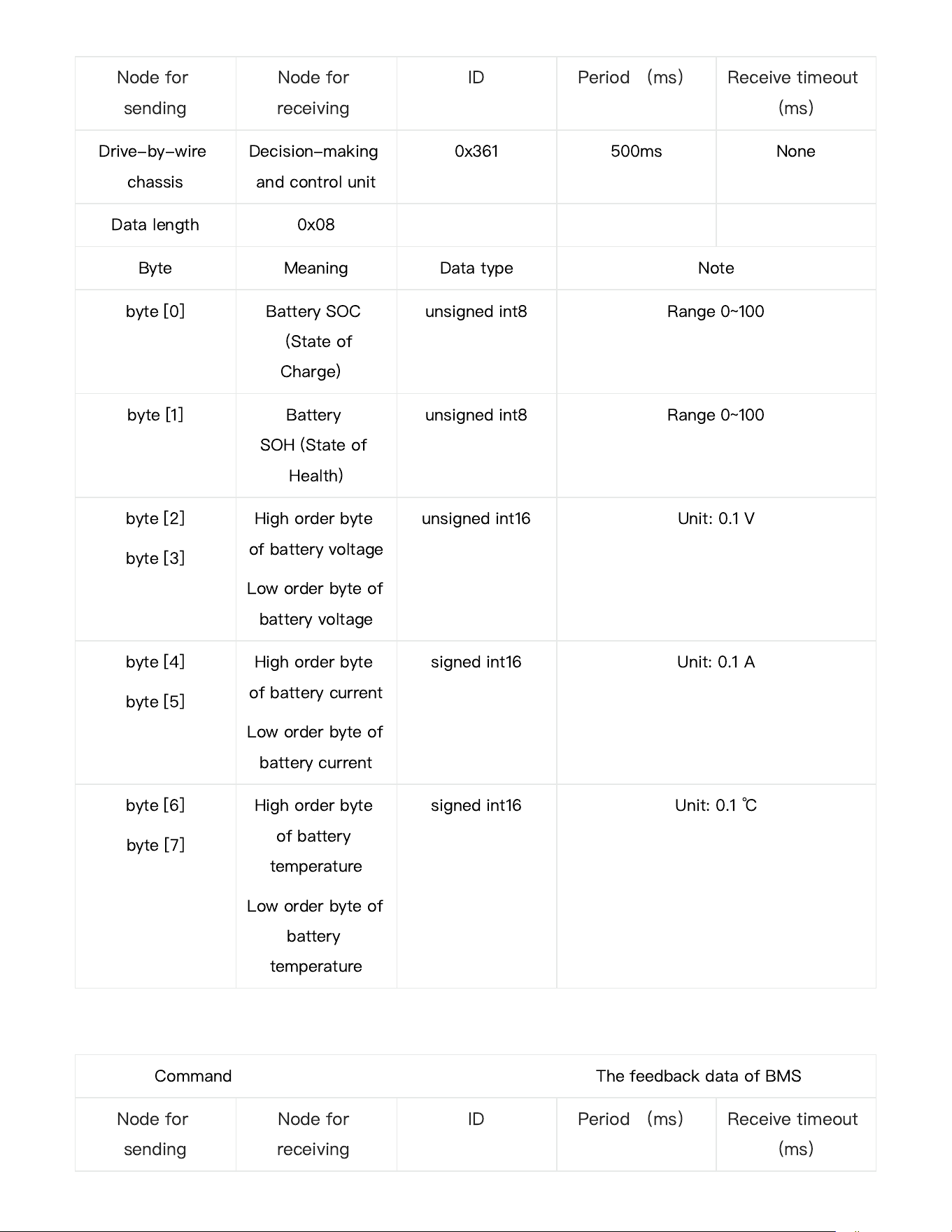
The remote controller information feedback frame is as follows
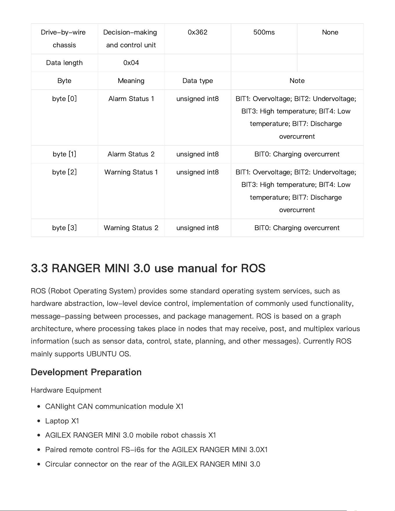
The feedback data ofBMS for all batteries, and the details of the protocol are as follows
CommandRemote controller
information feedback
Node for
sending
Node for
receiving
ID Period
(
ms
)
Receive timeout
(ms)
Drive-by-wire
chassis
Decision-making
and control unit
0x241
20ms
None
Data length
0x08
Byte
Description
Data type
Note
byte [0]
Remote control
SW feedback
unsigned int8
bit[0-1]: SWA:2- Up 3-Down
bit[2-3]: SWB : 2-Up 1-Middle 3-
Down
bit[4-5]: SWC : 2-Up 1-Middle 3-
Down
bit[6-7]: SWD
:
2-Up 3-Down
byte [1]
Right joystick left
and right
unsigned int8
Range:[-100,100]
byte [2]
Right joystick up
and down
unsigned int8
Range:[-100,100]
byte [3]
Left joystick up
and down
unsigned int8
Range:[-100,100]
byte [4]
Left joystick left
and right
unsigned int8
Range:[-100,100]
byte [5]
Left knob VRA
unsigned int8
Range:[-100,100]
byte [6]
Reserved
--
0x00
byte [7]
Count check
unsigned int8
0-255 Cycle count
Command The feedback data of BMS
40
Node for
sending
Node for
receiving
ID Period
(
ms
)
Receive timeout
(ms)
Drive-by-wire
chassis
Decision-making
and control unit
0x361
500ms
None
Data length
0x08
Byte
Meaning
Data type
Note
byte [0]
Battery SOC
(
State of
Charge
)
unsigned int8
Range 0~100
byte [1]
Battery
SOH(State of
Health)
unsigned int8
Range 0~100
byte [2]
byte [3]
High order byte
of battery voltage
Low order byte of
battery voltage
unsigned int16
Unit: 0.1 V
byte [4]
byte [5]
High order byte
of battery current
Low order byte of
battery current
signed int16
Unit: 0.1 A
byte [6]
byte [7]
High order byte
of battery
temperature
Low order byte of
battery
temperature
signed int16
Unit: 0.1
℃
Command The feedback data of BMS
Node for
sending
Node for
receiving
ID Period
(
ms
)
Receive timeout
(ms)
41
ROS (Robot Operating System) provides some standard operating system services, such as
hardware abstraction, low-level device control, implementation of commonly used functionality,
message-passing between processes, and package management. ROS is based on a graph
architecture, where processing takes place in nodes that may receive, post, and multiplex various
information (such as sensor data, control, state, planning, and other messages). Currently ROS
mainly supports UBUNTU OS.
Development Preparation
Hardware Equipment
CANlight CANcommunication module X1
Laptop X1
AGILEX RANGER MINI 3.0mobile robot chassis X1
Paired remote control FS-i6s for the AGILEX RANGER MINI 3.0X1
Circular connector on the rear of the AGILEX RANGER MINI 3.0
3.3 RANGER MINI 3.0use manual for ROS
●
●
●
●
●
Drive-by-wire
chassis
Decision-making
and control unit
0x362
500ms
None
Data length
0x04
Byte
Meaning
Data type
Note
byte [0]
Alarm Status 1
unsigned int8
BIT1: Overvoltage; BIT2: Undervoltage;
BIT3: High temperature; BIT4: Low
temperature; BIT7: Discharge
overcurrent
byte [1]
Alarm Status 2
unsigned int8
BIT0: Charging overcurrent
byte [2]
Warning Status 1
unsigned int8
BIT1: Overvoltage; BIT2: Undervoltage;
BIT3: High temperature; BIT4: Low
temperature; BIT7: Discharge
overcurrent
byte [3]
Warning Status 2
unsigned int8
BIT0: Charging overcurrent
42
Tested Development Environment
Ubuntu 18.04
ROS melodic
Git
Hardware Connection and Preparation
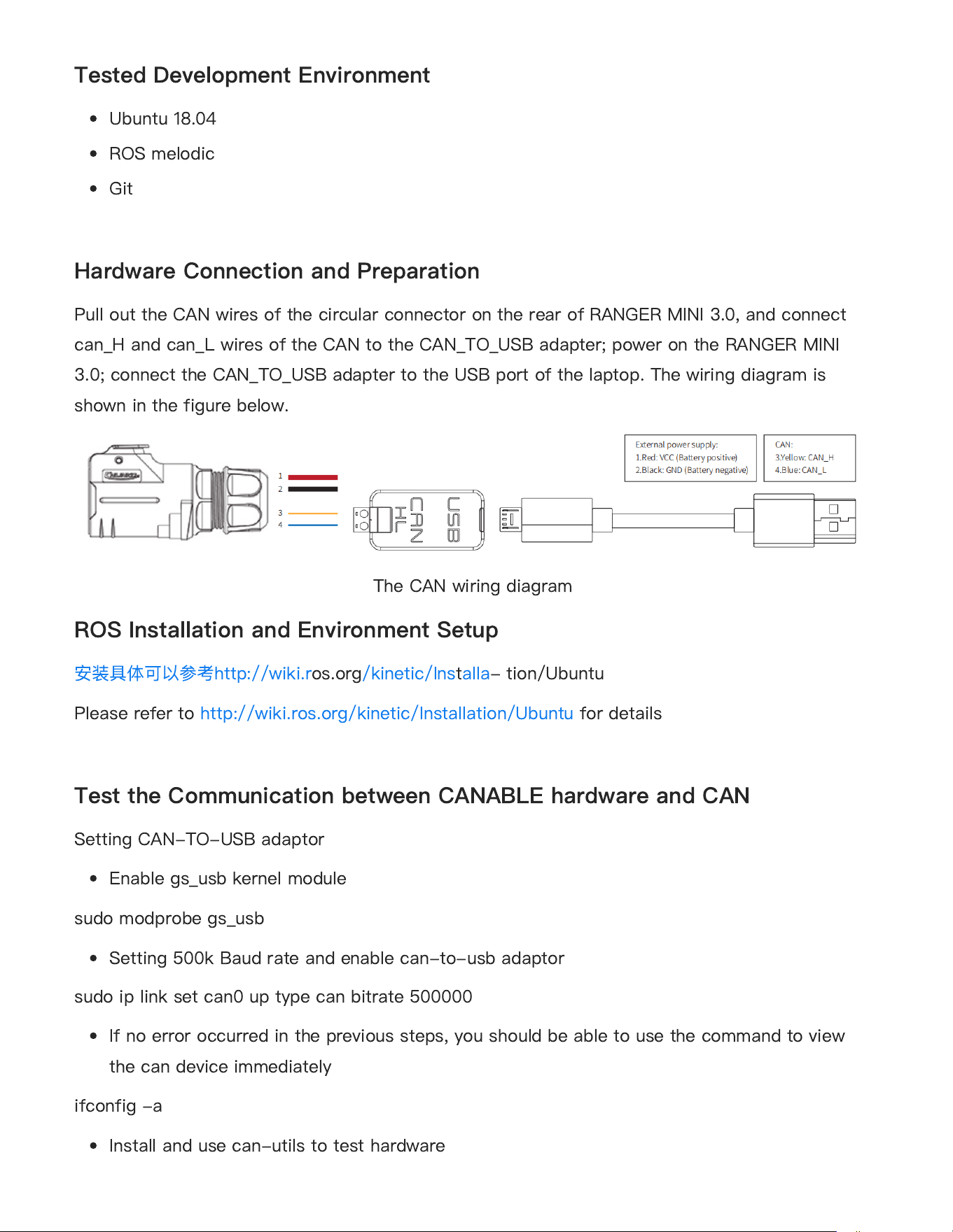
Pull out the CANwires of the circular connector on the rear of RANGER MINI 3.0, and connect
can_H and can_L wires of the CANto the CAN_TO_USB adapter; power onthe RANGER MINI
3.0; connect the CAN_TO_USB adapter to the USBport of the laptop. The wiring diagram is
shown in the figure below.
The CAN wiring diagram
ROS Installation and Environment Setup
安
装
具
体
可
以
参
考
http://wiki.ros.org/kinetic/Installa- tion/Ubuntu
Please refer to http://wiki.ros.org/kinetic/Installation/Ubuntu for details
Test the Communication between CANABLE hardware and CAN
Setting CAN-TO-USB adaptor
Enable gs_usb kernel module
sudo modprobe gs_usb
Setting 500k Baud rate and enable can-to-usb adaptor
sudo ip link set can0 up type can bitrate 500000
If no error occurred in the previous steps, you should be able to use the command to view
the can device immediately
ifconfig -a
Install and use can-utils to test hardware
●
●
●
●
●
●
●
43
sudo apt install can-utils
If the can-to-usb has been connected to the BUNKER robot this time, and the car has been
turned on, use the following commands to monitor the data from the BUNKER chassis
candump can0
Please refer to:
[1]https://github.com/agilexrobotics/agx_sdk
[2]https://wi-ki.rdu.im/_pages/Notes/Embedded-System/Linux/-can-bus-in-linux.html
AGILEX RANGER ROS PACKAGE download and compile
Download ros package
$ sudo apt install libasio-dev
$ sudo apt install ros-$ROS_DISTRO-teleop-twist-keyboard
Clone compile hunter_ros code
$ cd ~/catkin_ws/src
$ git clone --recursive https://github.com/agilexrobotics/ugv_sdk.git
$ git clone https://github.com/agilexrobotics/ranger_ros.git
$ cd ..
$ catkin_make
Please refer to
:
https://github.com/agilexrobotics/ranger_ros
Start the ROS node
Start the based node
roslaunch ranger_bringup ranger_minimal.launch
Note that the usb_to_can module equipped with Songling needs to be enabled before starting.
The enabling command is as follows: rosrun ranger_bringup bringup_can2usb.bash.
This command only needs to be executed once each time the usb_to_can module is powered on.
Start the keyboard remote operation node
roslaunch ranger_bringup ranger_teleop_keyboard.launch
●
●
●
●
●
44
Pay attention to the terminal printout and use the designated keys to control the RANGERMINI
movement.
Github ROS development package directory and usage instructions
*_base:: The core node for the chassis to send and receive hierarchical CAN messages. Based
on the communication mechanism of ros, it can control the movement of the chassis and read
the status of the RANGERMINI through the topic.
*_msgs: Define the specific message format of the chassis status feedback topic.
*_bringup: startup files for chassis nodes and keyboard control nodes, and scripts to enable the
usb_to_can module
In order to facilitate users to upgrade the
fi
rmware version used by RANGERMINI 3.0 and bring
customers a more complete experience, RANGERMINI 3.0 provides a
fi
rmware upgrade hardware
interface and corresponding client software.
Upgrade Preparation
AgilexCAN debugging moduleX 1
Micro USB cableX 1
RANGERMINI 3.0 chassisX 1
A computer (WINDOWS OS (Operating System))X 1
Upgrade Process
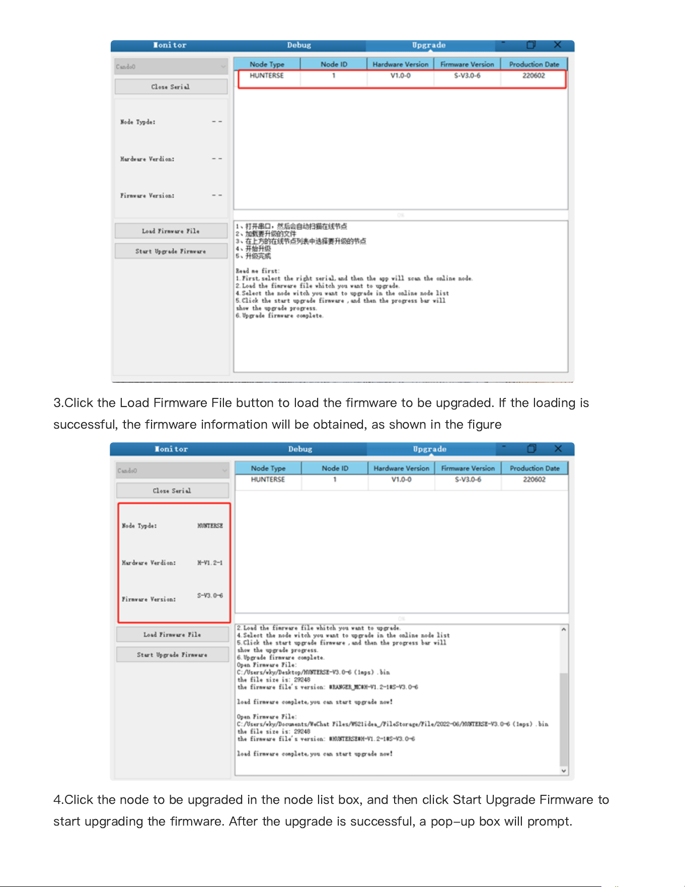
1.Plug in the USBTOCAN module on the computer, and then open the
AgxCandoUpgradeToolV1.3_boxed.exesoftware (the sequence cannot be wrong, first open the
software and then plug in the module, the device will not be recognized).
2.Click the Open Serialbutton, and then press the power button on the car body. If the
connection is successful, the version information of the main control will be recognized, as
shown in the figure.
3.4 Firmware Upgrade
●
●
●
●
45
3.Click the Load Firmware Filebutton to load the firmware to be upgraded. If the loading is
successful, the firmware information will be obtained, as shown in the figure
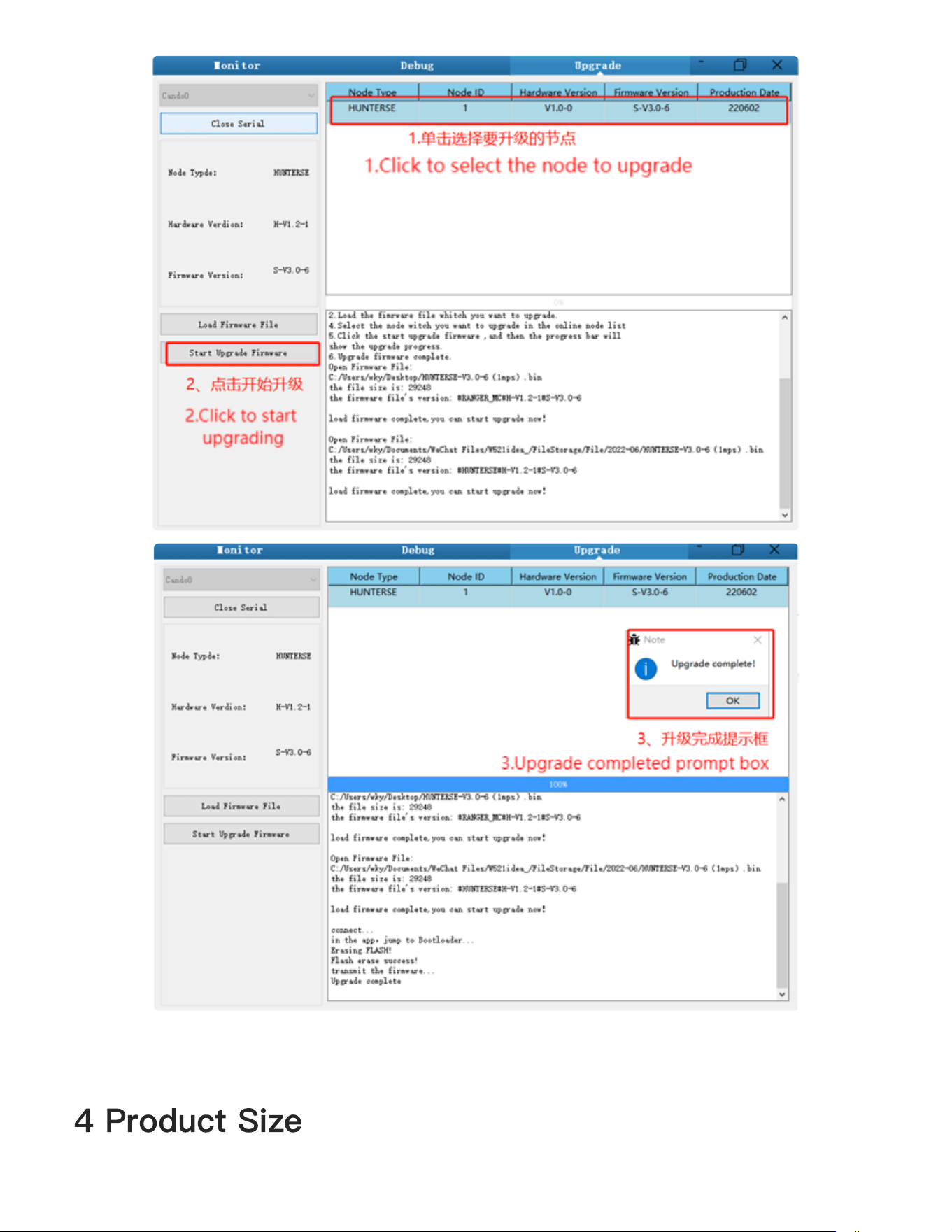
4.Click the node to be upgraded in the node list box, and then click Start Upgrade Firmware to
start upgrading the firmware. After the upgrade is successful, a pop-up box will prompt.
46
4Product Size

47