BFVK10B
OWNER’S MANUAL
BFVK10B-240821
2
IMPORTANT SAFETY INSTRUCTIONS
Before beginning any tness program, you should obtain a complete physical examination from your physician.
Il est conseille de subir un examen medical complet avant d’entreprendre tout programme d’exercise. Si vous
avez des etourdissements ou des faiblesses, arretez les exercices immediatement.
Antes de comenzar cualquier programma de ejercicios, deberias tener un examen sico con su doctor.
When using exercise equipment, you
should always take basic precautions,
including the following:
• Read all instructions before using the BFVK10B. These
instructions are written to ensure your safety and to
protect the unit.
• Do not allow children on or near the equipment.
• Use the equipment only for its intended purpose as
described in this guide. Do not use accessory
attachments that are not recommended by the
manufacturer. Such attachments might cause injuries.
• Wear proper exercise clothing and shoes for your
workout, no loose clothing.
• Use care when getting on or off the unit.
• Do not overexert yourself or work to exhaustion.
• If you feel any pain or abnormal symptoms, stop your
workout immediately and consult your physician.
• Never operate unit when it has been dropped or
damaged. Return the equipment to a service center for
examination and repair.
• Never drop or insert objects into any opening in the
equipment.
• Always check the unit and its cables before each
use. Make sure that all fasteners and cables are secure
and in good working condition.
• Do not use the equipment outdoors or near water.
• Max Chin Up User Weight - 250lb.
• Max Dip Bar User Weight - 250lb.
• Max Knee Raise User Weight - 300lb.
Personal Safety During Assembly
• It is strongly recommended that a qualified dealer
assemble the equipment. Assistance is required.
• Before beginning assembly, please take the time to
read the instructions thoroughly.
• Read each step in the assembly instructions and
follow the steps in sequence. Do not skip ahead. If
you skip ahead, you may learn later that you have to
disassemble components and that you may have
damaged the equipment.
• Assemble and operate the BFVK10B on a solid, level
surface. Locate the unit a few feet from the walls or
furniture to provide easy access.
The BFVK10B is designed for your enjoyment. By
following these precautions and using common
sense, you will have many safe and pleasurable hours
of healthful exercise with your Best Fitness BFVK10B.
After assembly, you should check all functions to
ensure correct operation. If you experience problems,
rst recheck the assembly instructions to locate any
possible errors made during assembly. If you are unable
to correct the problem, call the dealer from whom
you purchased the machine or call 1-800-556-3113
for the dealer nearest you.
Obtaining Service
Please use this Owner’s Manual to make sure that all
parts have been included in your shipment. When
ordering parts, you must use the part number and
description from this Owner’s Manual. Use only
Best Fitness replacement parts when servicing this
machine. Failure to do so will void your warranty and
could result in personal injury.
For information about product operation or service,
go to www.besttness.com or contact an authorized
Best Fitness dealer or a Best Fitness factory-authorized
service company or contact Best Fitness customer
service at one of the following:
Toll Free: 1-800-556-3113
Phone: 1-708-427-3555
Fax: 1-708-427-3556
Hours: M-F 8:30-5:00 CST
E-Mail: [email protected]
Or write to: Best Fitness
Service Department
1900 S. Des Plaines Ave.
Forest Park, IL 60130 USA
Retain this Owner’s Manual for future
reference. If you need to order replacement
parts please be prepared to provide the
following information when contacting us so we
can assist you better.
1. Model Number
2. Place of Purchase
3. Serial Number (S/N)
4. Part # and Description
3
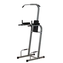
Thank you for purchasing the Best Fitness BFVK10B. This gym is part of the Best Fitness quality strength
training machines, which lets you target speci
c muscle groups to achieve better muscle tone and overall body
conditioning. To maximize your use of the equipment please study this Owner’s Manual thoroughly.
BEFORE YOU BEGIN
Body-Solid continually seeks ways to improve the performance, specications and product manuals in order to
ensure that only superior products are released from our factories. Please take the time to carefully read through this
manual thoroughly. Instructions contained in this document are not intended to cover all details or variations possible
with Body-Solid equipment, or to cover every contingency that may be met in conjunction with installation, operation,
maintenance or troubleshooting of the equipment. Even though we have prepared this manual with extreme care, nei-
ther the publisher nor the author can accept responsability for any errors in, or omission from, the information given.
Should additional information be required, or should situations arise that are not covered by this manual, the matter
should be directed to your local Body-Solid representative, or the Service Department at Body-Solid Inc. in Forest
Park, Illinois.
Any Questions?
Call (800) 556-3113
Required Tools
The basic tools that you must obtain before assembling
the BFVK10B include but are not limited to:
- Standard Wrench Set
- Metric Wrench Set
- Adjustable Wrench
Installation Requirements
Follow these installation requirements when assembling
the BFVK10B:
Set up the BFVK10B on a solid, flat surface. A smooth,
at surface under the unit helps keep it level. A
level unit has fewer malfunctions.
Provide ample space around the unit. Open
space around the machine allows for easier access.
Insert all bolts in the same direction. For aesthetic
purposes, insert all bolts in the same direction unless
specied (in text or illustrations) to do otherwise.
Leave room for adjustments. Tighten fasteners such as
bolts, nuts, and screws so the unit is stable, but leave
room for adjustments. Do not fully tighten fasteners
until instructed in the assembly steps to do so.
Fill out and mail the warranty card.
Assembly Tips
Read all “Notes” on each page before beginning each
step.
While you may be able to assemble the BFVK10B using
the illustrations only, important safety notes and other
tips are included in the text.
Some pieces may have extra holes that you will not use.
Use only those holes indicated in the instructions and
illustrations.
NOTE: With so many assembled parts, proper
alignment and adjustment is critical. While
tightening the nuts and bolts, be sure to leave
room for adjustments.
NOTE: The bottles that are marked “Poison” is your
touch up paint. Keep away from children.
CAUTION: Obtain assistance! If you feel like you
can’t assemble the BFVK10B by yourself
then do not attempt to do so as this could
result in injury. Review the Installation
Requirements before proceeding with the
following steps.
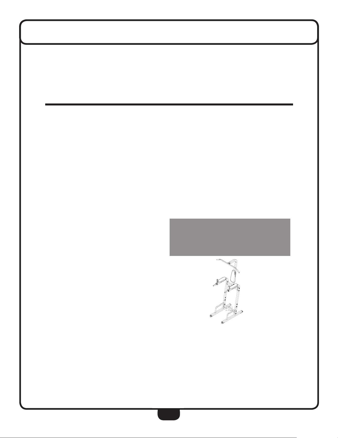
Your S/N# can be
found here.
↑

4
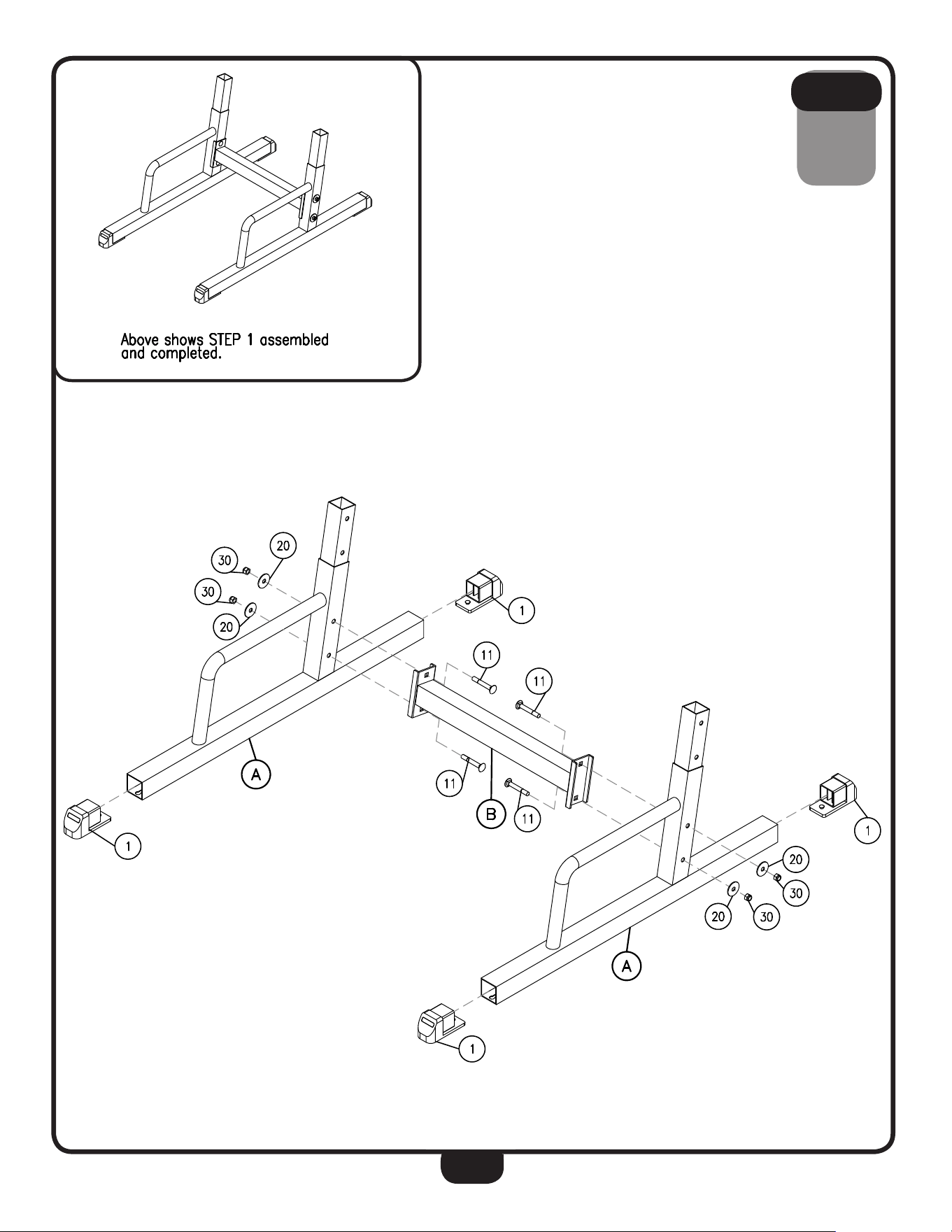
1A. Attach Foot Tube Assembly (A) to Lower Middle Tube Assembly (B) using:
Two 11 (M10X65mm Carriage Bolt)
Two 20 (M10 Large Washer)
Two 30 (M10 Nylon Lock Nut)
1B. Attach second Foot Tube Assembly (A) to Lower Middle Tube Assembly (B) using:
Two 11 (M10X65mm Carriage Bolt)
Two 20 (M10 Large Washer)
Two 30 (M10 Nylon Lock Nut)
1C. Install four 50X50mm Foot Caps (1) to the ends of both Foot Tube Assemblies (A)
as shown in the diagram.
STEP
1
Be careful to assemble all components
in the sequence they are presented.
NOTE:
Finger tighten all hardware in this step. DO NOT wrench tighten until the last step.
Some components may be pre-assembled. Nylon lock nuts will not fully screw onto
bolts, they must be wrench tighten to fully go on.
5
STEP
1
6
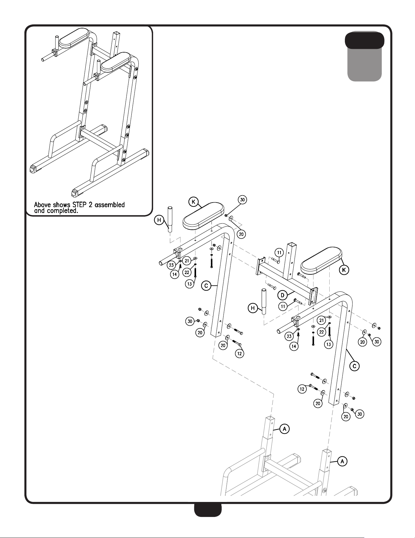
2A. Slide both Elbow Tube Assembly (C) onto Foot Tube Assembly (A).
2B. Atach Upper Tube Assembly (D) to each Elbow Tube Assembly (C) using a total of:
Four 11 (M10X65mm Carriage Bolt)
Four 20 (M10 Large Washer)
Four 30 (M10 Nylon Lock Nut)
2C. Secure each Elbow Tube Assembly (C) to Foot Tube Assembly (A) using a total of:
Four 12 (M10X65mm Hex Head Bolt)
Four 20 (M10 Large Washer)
Four 30 (M10 Nylon Lock Nut)
2D. Install an Elbow Pad (K) to each Elbow Tube Assembly (C) using a total of:
Four 13 (M8X65mm Hex Head Bolt)
Four 22 (M8 Spring Washer)
Four 21 (M8 Washer)
2E. Connect a Handle Tube (H) to each Elbow Tube Assembly (C) using a total of:
Two 14 (M10X20mm Hex Head Bolt)
Two 23 (M10 Washer)
STEP
2
Be careful to assemble all components
in the sequence they are presented.
NOTE:
Finger tighten all hardware in this step. DO NOT wrench tighten until the last step.
Some components may be pre-assembled. Nylon lock nuts will not fully screw onto
bolts, they must be wrench tighten to fully go on.
7
STEP
2

8
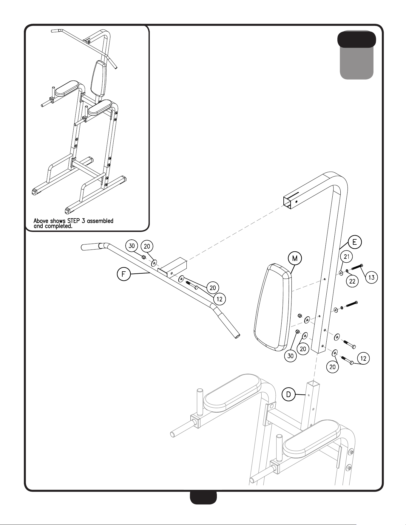
3A. Slide Back Tube Assembly (E) onto Upper Tube Assembly (D) and connect using:
Two 12 (M10X65mm Hex Head Bolt)
Four 20 (M10 Large Washer)
Two 30 (M10 Nylon Lock Nut)
3B. Attach Back Pad (M) onto Back Tube Assembly (E) using:
Two 13 (M8X65mm Hex Head Bolt)
Two 22 (M8 Spring Washer)
Two 21 (M8 Washer)
3C. Slide Lat Bar Assembly (F) onto Back Tube Assembly (E) and secure using:
One 12 (M10X65mm Hex Head Bolt)
Two 20 (M10 Large Washer)
One 30 (M10 Nylon Lock Nut)
STEP
3
Be careful to assemble all components
in the sequence they are presented.
NOTE:
Finger tighten all hardware in this step. DO NOT wrench tighten until the last step.
Some components may be pre-assembled. Nylon lock nuts will not fully screw onto
bolts, they must be wrench tighten to fully go on.
9
STEP
3
10
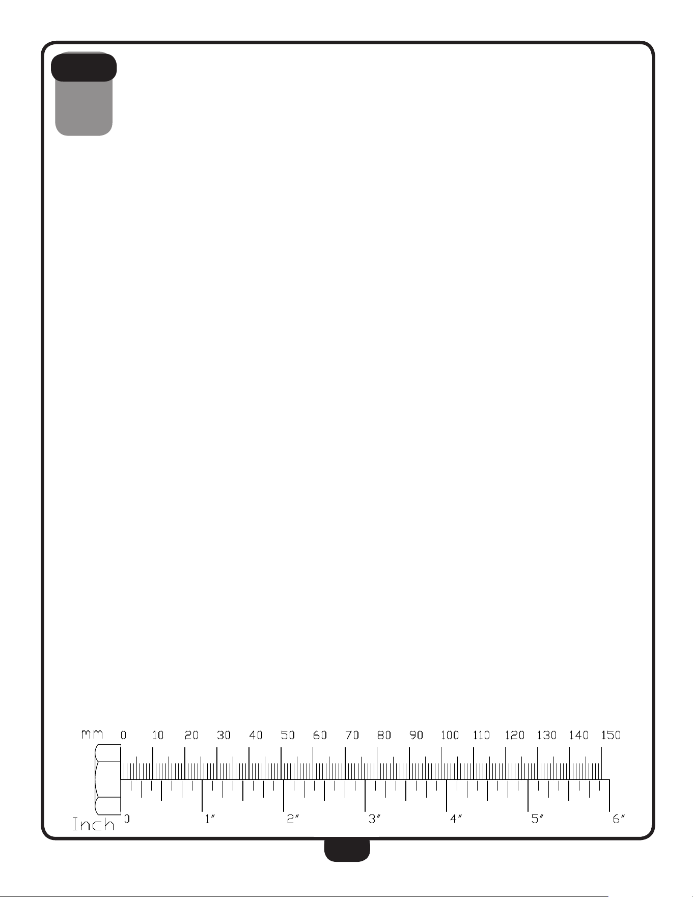
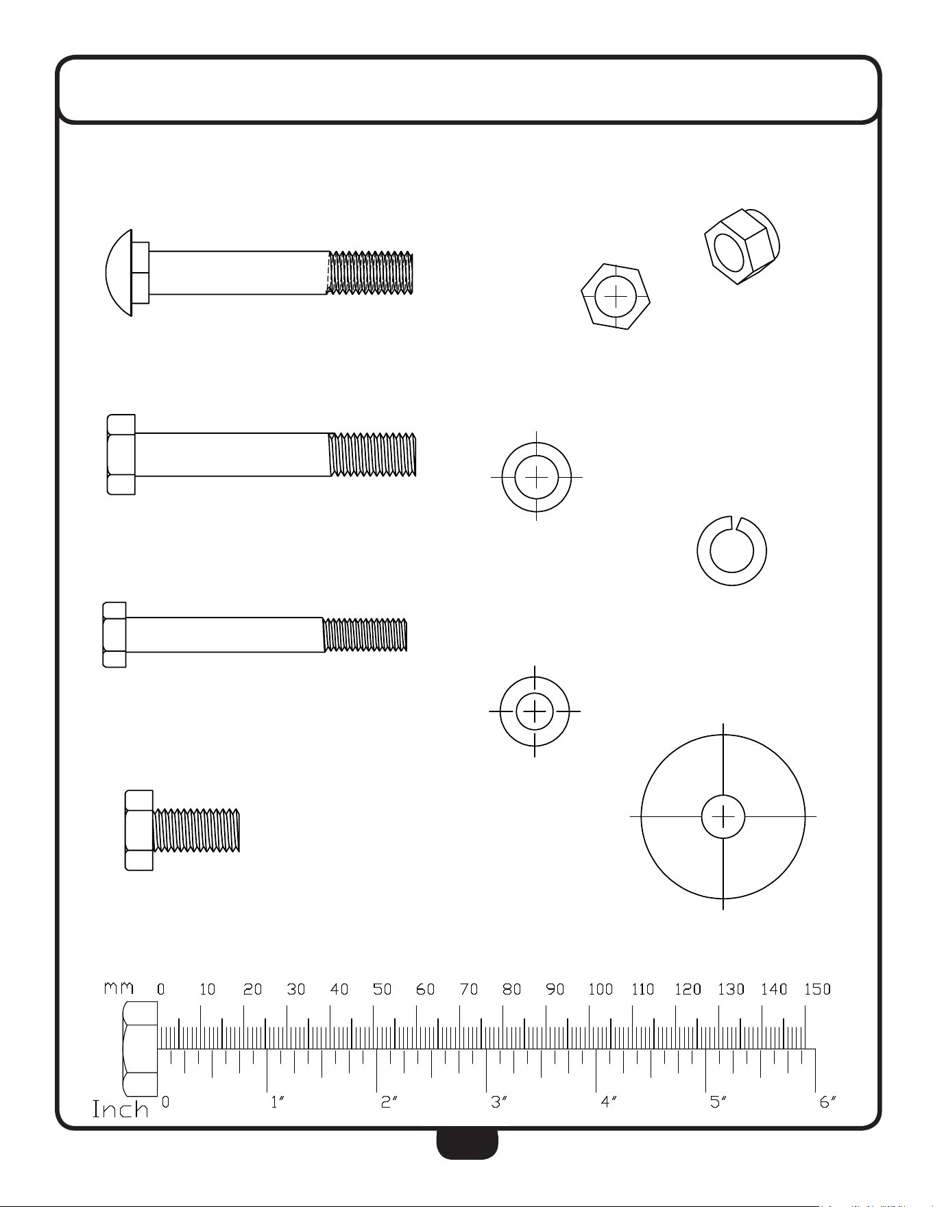
HARDWARE
(Actual Size Shown)
KEY #11 M10X65 Carriage Bolt
KEY #12 M10X65 Hex Head Bolt
KEY #13 M8X65 Hex Head Bolt
KEY #14 M10X20 Hex Head Bolt
HARDWARE
(Actual Size Shown)
KEY #30 M10 Nylon Lock Nut
KEY #21 φ8 Washer
KEY #22 φ8 Spring Washer
KEY #23 φ10 Washer
KEY #20 φ10 Large Washer
HARDWARE
(Actual Size Shown)
KEY #30 M10 Nylon Lock Nut
KEY #21 φ8 Washer
KEY #22 φ8 Spring Washer
KEY #23 φ10 Washer
KEY #20 φ10 Large Washer
HARDWARE
(Actual Size Shown)
KEY #30 M10 Nylon Lock Nut
KEY #21 φ8 Washer
KEY #22 φ8 Spring Washer
KEY #23 φ10 Washer
KEY #20 φ10 Large Washer
HARDWARE
(Actual Size Shown)
KEY #30 M10 Nylon Lock Nut
KEY #21 φ8 Washer
KEY #22 φ8 Spring Washer
KEY #23 φ10 Washer
KEY #20 φ10 Large Washer
HARDWARE
(Actual Size Shown)
KEY #30 M10 Nylon Lock Nut
KEY #21 φ8 Washer
KEY #22 φ8 Spring Washer
KEY #23 φ10 Washer
KEY #20 φ10 Large Washer
HARDWARE
(Actual Size Shown)
11
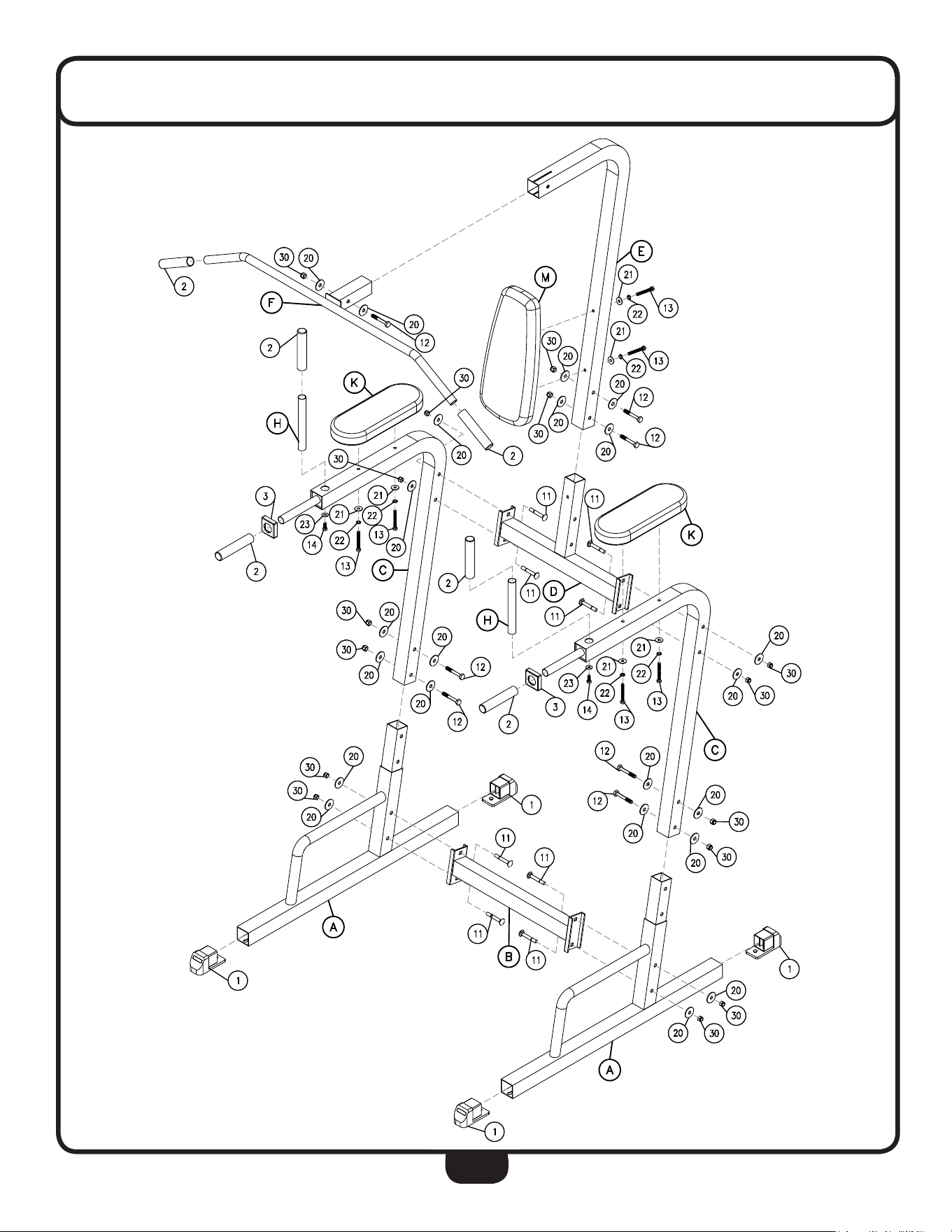
HARDWARE LIST
PART# QTY DESCRIPTION
A 2 Foot Tube Assembly
B 1 Lower Middle Tube Assembly
C 2 Elbow Tube Assembly
D 1 Upper Tube Assembly
E 1 Back Tube Assembly
F 1 Lat Bar Assembly
H 2 Handle Tube
K 2 Elbow Pad
M 1 Back Pad
1 4 M50X50mm Foot Cap
2 6 Plastic Sleeve
3 2 M50 End Cap
11 8 M10X65mm Carriage Bolt
12 7 M10X65mm Hex Head Bolt
13 6 M8X65mm Hex Head Bolt
14 2 M10X20mm Hex Head Bolt
20 22 M10 Large Washer
21 6 M8 Washer
22 6 M8 Spring Washer
23 2 M10 Washer
30 15 M10 Nylon Lock Nut
Part numbers are required when ordering parts.
12
EXPLODED VIEW DIAGRAM

13
BFVK10B NOTES

1900 S. Des Plaines Ave.
Forest Park, Il 60130
1 (800) 556-3113
Hours: M-F 8:30 - 5:00 CST
c
Copyright 2003. Body-Solid. All rights reserved. Body-Solid reserves the right to change design and specications when we feel it will improve
the product.
www.BestFitness.com
BFVK10B
S/N # 002692-��-��-����-����
please write your serial number in the boxes below