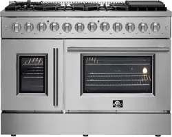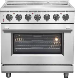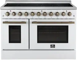
FORNO 48” Electric Range
FFSEL6011-48
FFSEL6011-48WHT
FFSEL6011-48BLK
1
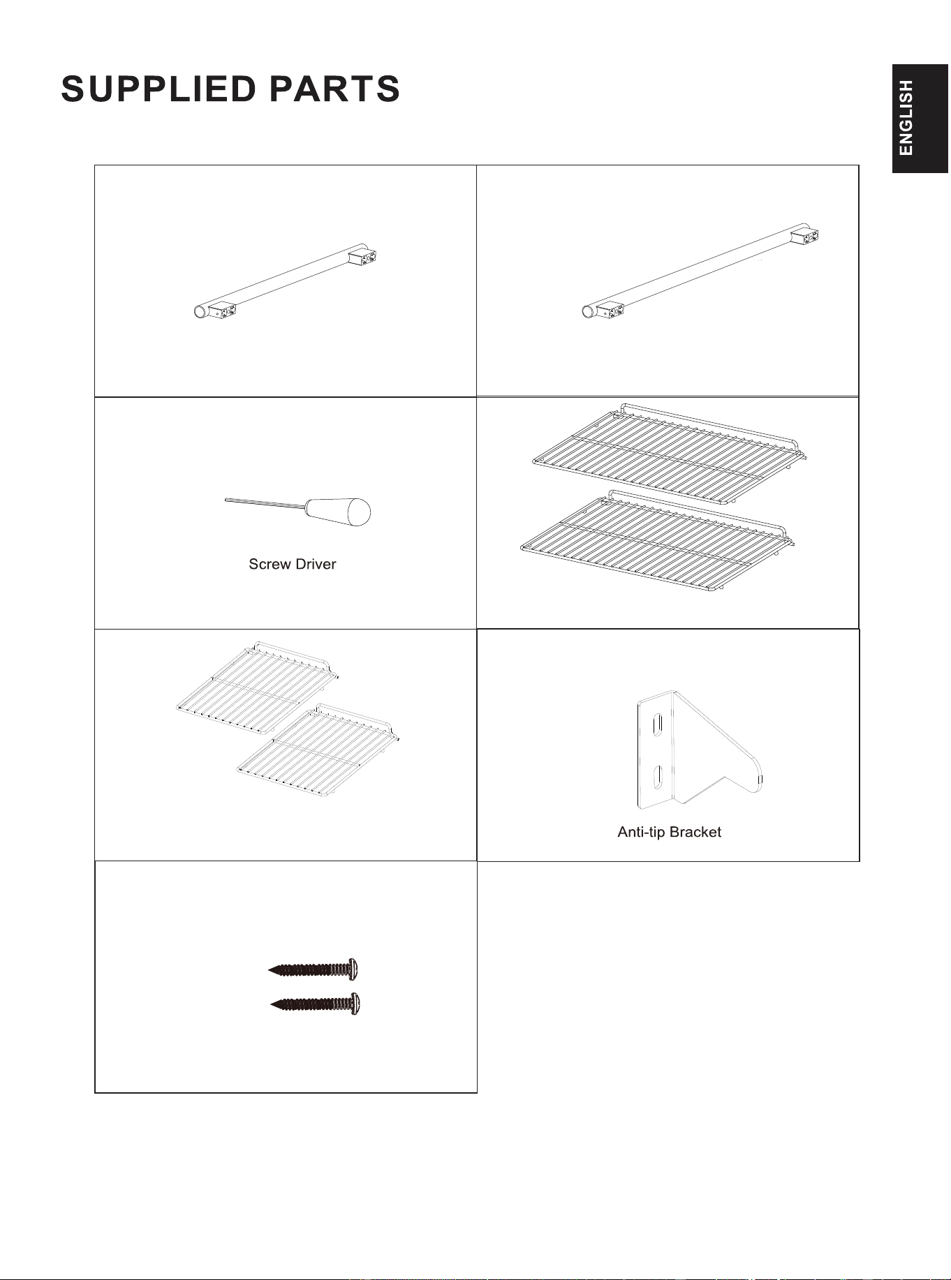
(1PC)
ST 1/5”x 2 1/5”Screws (2PCS)
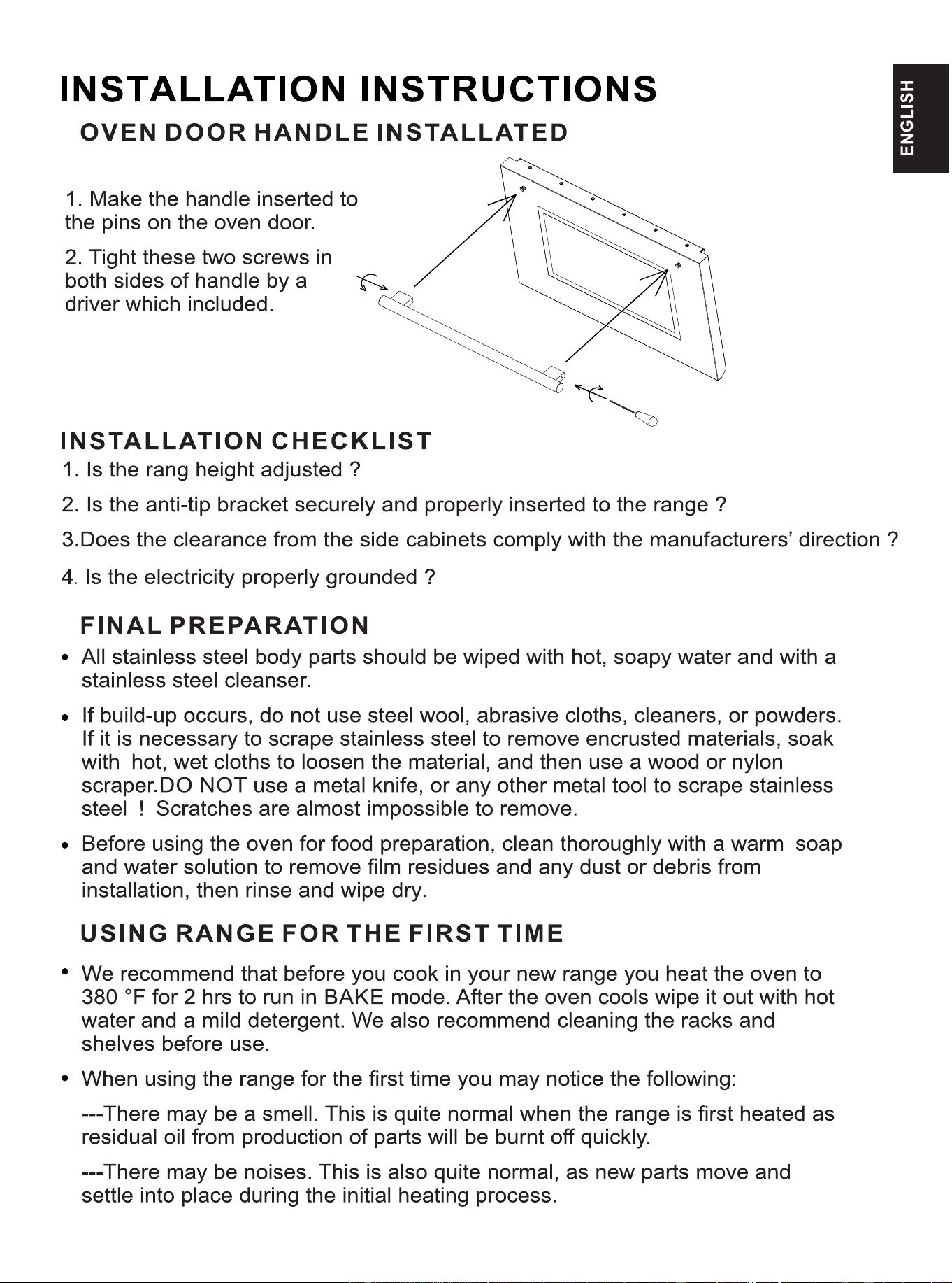
18” Oven Door Handle (1PC) 30” Oven Door Handle (1PC)
18” Oven Shelf (2pcs)
30” Oven Shelf (2pcs)
(1PC)
2
3
4
6
7
8
9
10
11
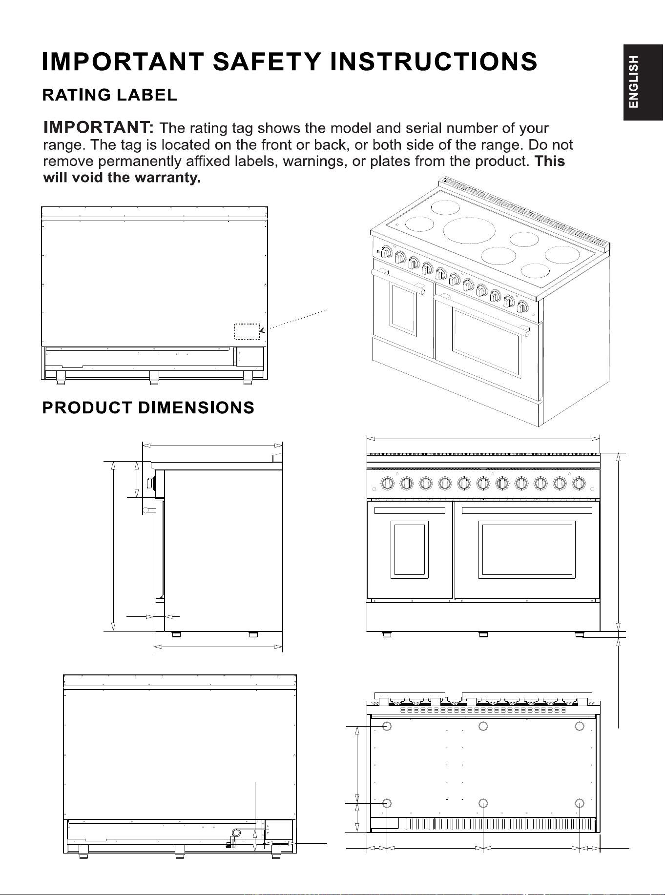
Rating label
100W
1200W
1200W
1200W
2000W
2000W
3300W
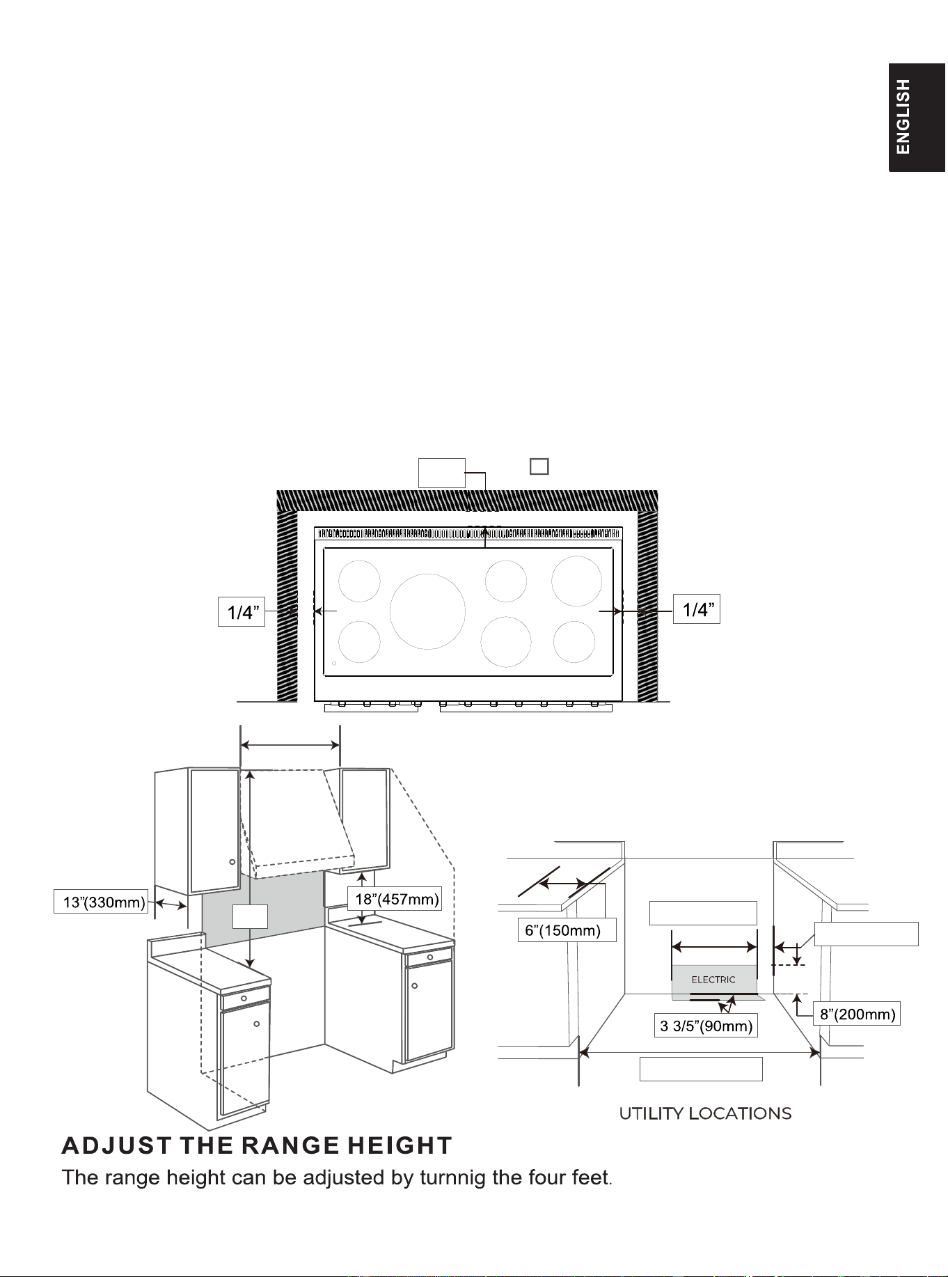
48”
36 7/10”1 3/20”(adjustable)
48”
7 1/2”
34 17/20”
1 3/4”
26”
4 1/5” 19 4/5”
19 4/5”
4 1/5”
15 4/5”
6”
4 4/5”
6 1/2”
12
1”
Counter
Top
48”(1220mm)
48 1/2”(1232mm)
Counter
Top
4”(100mm)
31 1/2”(800mm)
A = 30 inches(760mm) minimum clearance between
the top of the cooking surface and the bottom
of an unprotected wood or metal cabinet
muZ
A
13
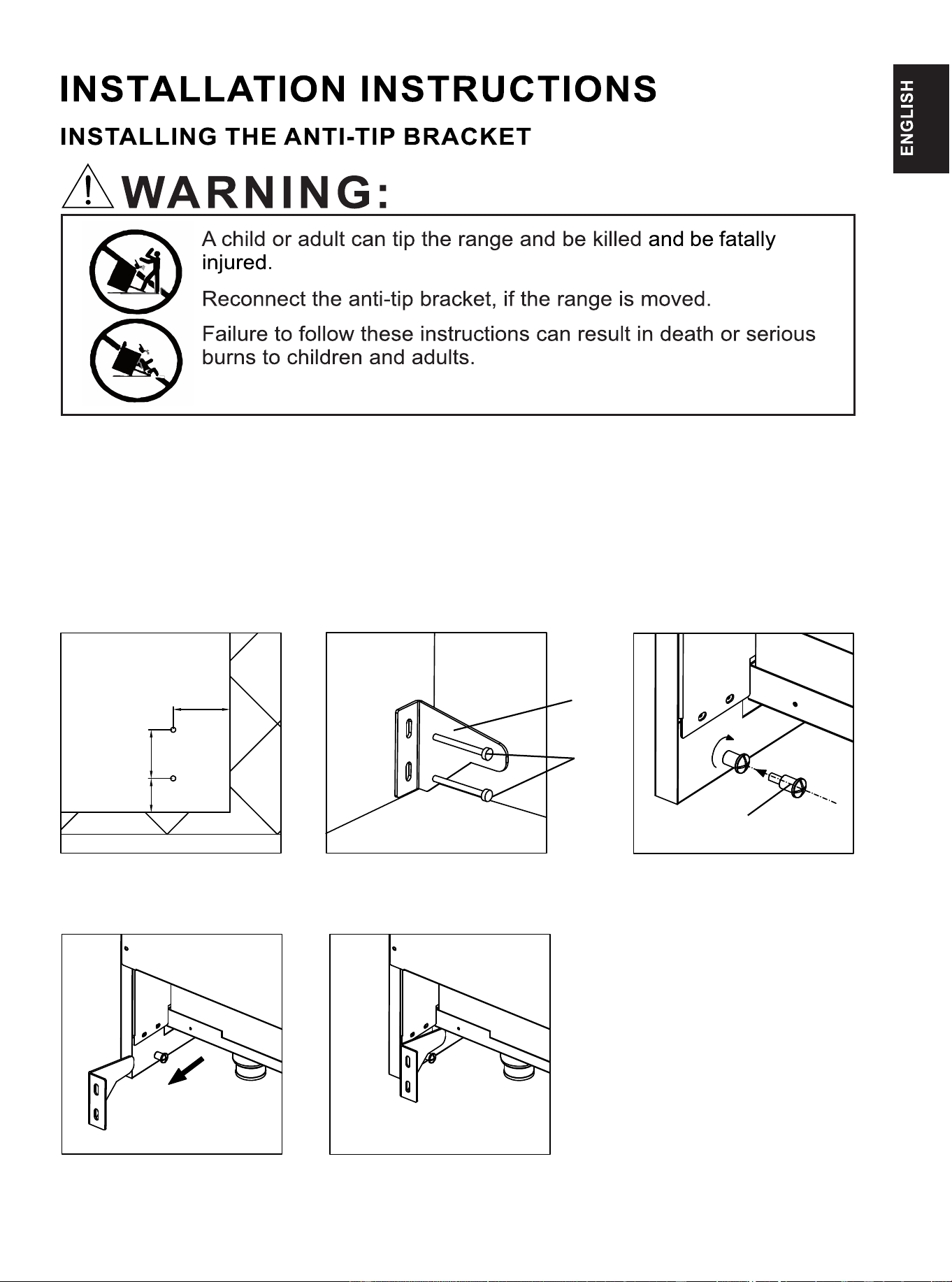
To reduce the risk of tipping the appliance, the appliance must be secured by
properly installed anti-tip device packed with the appliance. All ranges can tip and cause injuries.
Install anti-tip device packaged with range.Follow all Installation Instructions.
Make sure the anti-tip bracket is installed:
Slide range forward.
Make sure the anti-tip bracket is securely attached to the wall behind the range.
Safely tilt the front of the range upward slightly and move back against wall, making sure the
pin slides under bracket.
1 4/5”
1”
1 1/2”
A)Locate the installation
position of the anti-tip bracket
on the wall
①
②
NO TE:
① Anti-tip Bracket (1)
② ST 1/5”x 2 1/5”Screws (2)
③ M6 Step Screw (1)(It has been
preinstalled on the side panels)
③
B)The anti-tip bracket must be
securely mounted to the wall.
C)Make sure the step screw is
tightened in the nut hole of
the side panels
D)Slide the oven close to the
wall and make sure the step
screw under the anti-tip bracket
14
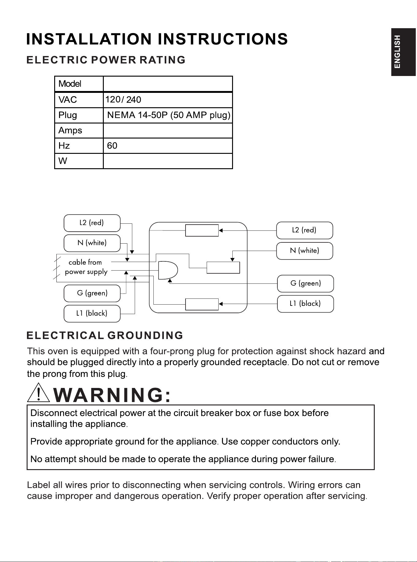
FFSEL6011-48
50
17000
15
2x6/2x8 AWG
16
17
18
ENERGY REGULATOR
Each radiant cooker element has its own energy regulator, which is used to control
the working frequency of the radiant element to achieve different heating effects.
From LO to HI, the working frequency is gradually increased, and the heating time is
also increased.
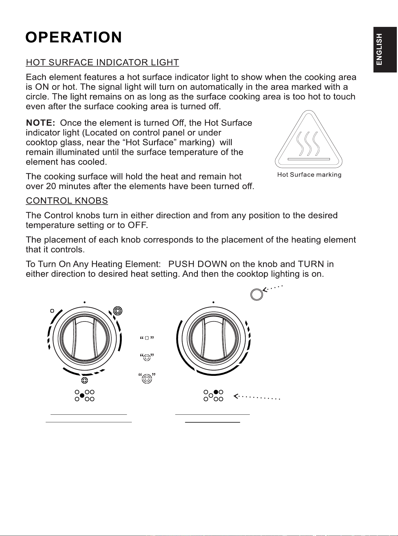
RADIANT ELEMENT
This type of electric element uses a wire ribbon located under the glass surface to
provide the heat for cooking. Turn the knob from LO to HI, the radiant element will be
turn on and off frequently with the working time.
LO
HI
HI
HI
LO
LO
Push
OFF OFF
HI
LO
Push
Cooktop
19
Eclairage
BOUTON DE L'ÉLÉMENT
RADIANT À TRIPLE ANNEAU
BOUTON DE L'ÉLÉMENT
RADIANT SIMPLE
Marquage de l'emplacement
de l'élément chauffant
Bague en anneau
Double anneau
anneau triple
20
21
22
The control knob can be turn both side for setting cooking function. After the knob
(red light)
turn on, the indicator light is on.
This setting uses the top outer heating element , bottom
Low Bake:
This setting uses both the top inner and outer heating element.
Take care to reset all worktop/ oven controls to the OFF position after use of
the appliance.
This setting uses the rear heating element , the bottom
heating element and the convection fan.
This setting uses both the top heating element and the
This setting uses only the bottom heating element.
convection fan.
heating element and convection fan.
23
30” OVEN CONTROL KNOBS
The control knob can be turn both side for setting cooking function. After the knob
(red light)
turn on, the indicator light is on.
This setting uses the top outer heating element , bottom
Take care to reset all worktop/ oven controls to the OFF position after use of
the appliance.
This setting uses the bottom heating element and the
convection fan.
heating element and convection fan.
This setting uses the top heating element and the
convection fan.
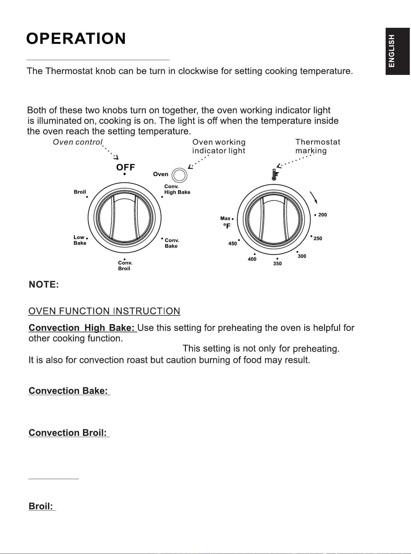
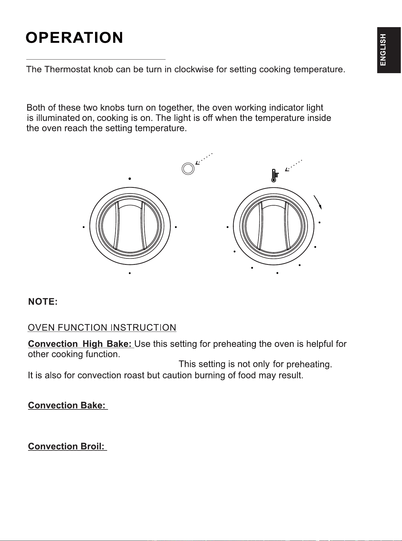
Max
450
400
350
300
250
200
°F
OFF
Conv.
High
Bake
Conv.
Bake
Conv.
Broil
Oven
Oven working
indicator light
Thermostat
marking
24
18” OVEN CONTROL KNOBS
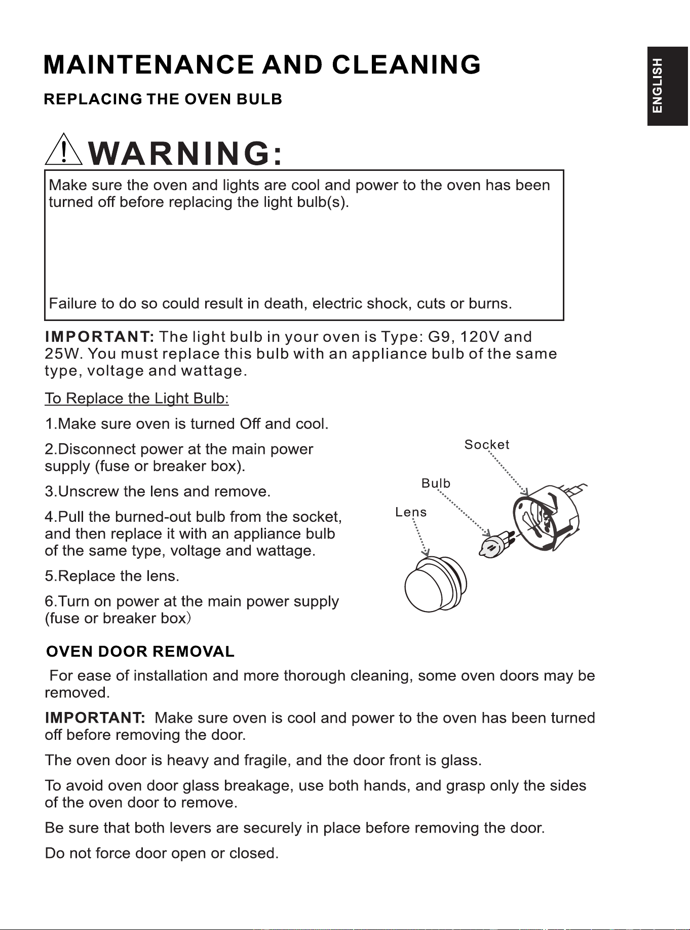
The lens must be in place when using the oven.
The lens serves to protect the light bulb from breaking.
The lens is made of glass.Handle carefully to avoid breakage.
25
26
27
28
29
30
31
32
33