
One-Touch Remote Control for ACO DSPs
CONDUCTOR / PRO
User Manual
Bedienungsanleitung
de
en

2
Inhaltsverzeichnis
1. Allgemeine Hinweise ................................................................................................................... 4
2. Einbauhinweise & Installation ..................................................................................................... 5
2.1 Montage des CONDUCTOR PROs ....................................................................................................................5
2.2 Montage des CONDUCTORs .............................................................................................................................6
2.3 Anschluss des CONDUCTOR / PRO an einen DSP / DSP-Verstärker ............................................................ 7
3. Bedienung des CONDUCTOR / PROs ........................................................................................... 8
3.1 VolumeControlConguration(Lautstärkemenü1-4) ................................................................................. 10
3.2 ToneControl menu ............................................................................................................................................ 10
3.3 SignalInputselectionmenu(Signalquellenauswahlmenü) ......................................................................... 11
3.4 SoundSetupselectionmenu(SoundSetup-Auswahlmenü) ....................................................................... 11
3.5 BluetoothPlaybackControlmenu(BluetoothWiedergabesteuerungsmenü) ........................................... 12
4.KongurationinderDSPPC-ToolSoftware .............................................................................. 13
4.1 GeneralConguration(AllgemeineKonguration) ...................................................................................... 13
4.1.1 Mainmenu(Hauptmenü) ....................................................................................................................... 13
4.1.2 AutomaticswitchbacktoMainmenu(AutomatischeUmschaltungzumHauptmenü) .................. 13
4.1.3 Menü-Aktivierung ................................................................................................................................... 14
4.1.4LEDbrightness(LED-Helligkeit) ........................................................................................................... 14
4.1.5 LEDDimming(LED-Dimmung) ............................................................................................................. 14
4.1.6 Installationorientation(AnpassungandieEinbauposition) ............................................................. 14
4.2 VolumeControlConguration(KongurationderLautstärkeregelungen) ................................................ 14
4.2.1 Lautstärkenauswahl ............................................................................................................................... 14
4.2.2 AssignedVolumecontrol(Lautstärkezuweisung) .............................................................................. 14
4.2.3 Assignedcolor(Farbzuweisung) .......................................................................................................... 15
4.2.4 Volumecontrolrange(Lautstärkeregelbereich) .................................................................................. 15
4.2.5 StartupVolume(Einschalt-Lautstärke) ................................................................................................ 15
4.3 ToneControl ...................................................................................................................................................... 16
4.4 CONDUCTORStatus ........................................................................................................................................16
4.5 CONDUCTOREinstellungenladenundzurücksetzen ..................................................................................16
5.Standard-Konfiguration ............................................................................................................. 17
6.Problembehandlung ................................................................................................................... 18
7. Technische Daten ....................................................................................................................... 20
8. Rechtliche Hinweise .................................................................................................................. 22

3
HerzlichenGlückwunsch
Sehr geehrter Kunde,
Wir gratulieren Ihnen zum Kauf dieser hochwertigen Bedieneinheit mit RGB-LED Feedback.
Der CONDUCTOR / PRO wurde von uns nach neuesten technischen Erkenntnissen entwickelt und zeichnet sich durch
eine hervorragende Verarbeitung und eine überzeugende Anwendung ausgereifter Technologien aus.
Viel Freude an diesem Produkt wünscht Ihnen das
Team von
AUDIOTEC FISCHER
de
4
1.AllgemeineHinweise
Um alle Möglichkeiten des Produktes optimal ausschöpfen zu können, lesen Sie bitte sorgfältig die nachfolgenden In-
stallationshinweise. Wir garantieren, dass jedes Gerät vor Versand auf seinen einwandfreien Zustand überprüft wurde.
Wir empfehlen, die Installation von einem Einbauspezialisten vornehmen zu lassen, da der Nachweis eines fachge-
rechten Einbaus und Anschlusses des Gerätes Voraussetzung für die Garantieleistungen sind.
Installieren Sie Ihren CONDUCTOR an einer trockenen Stelle im Auto. Montieren Sie das Gerät nicht in der Nähe von
wärmeabstrahlenden Teilen oder elektronischen Steuerungen des Fahrzeuges.
ImSinnederUnfallsicherheitmussderCONDUCTORprofessionellbefestigtwerden,damitdieBedieneinheit
keineGefahrfürdieInsassenund/oderdasFahrzeugwährendeinerkritischenFahrsituation,wiebeispiels-
weiseeinerGefahrenbremsung,darstellt.
Informationen zum fachgerechten Einbau nden Sie im Kapitel „Einbauhinweise & Installation“ auf den folgenden Seiten.
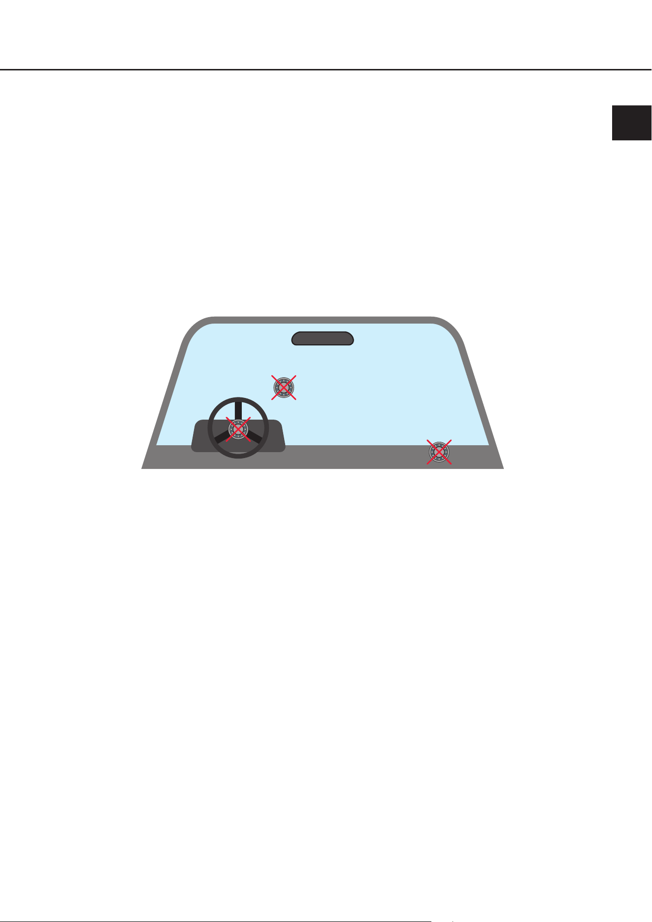
Wichtig: Achten Sie bei der Montage darauf, dass keine Sicherheitssysteme Ihres Fahrzeugs (bspw. Airbag) in ihrer
Wirkung beeinträchtigt werden können.
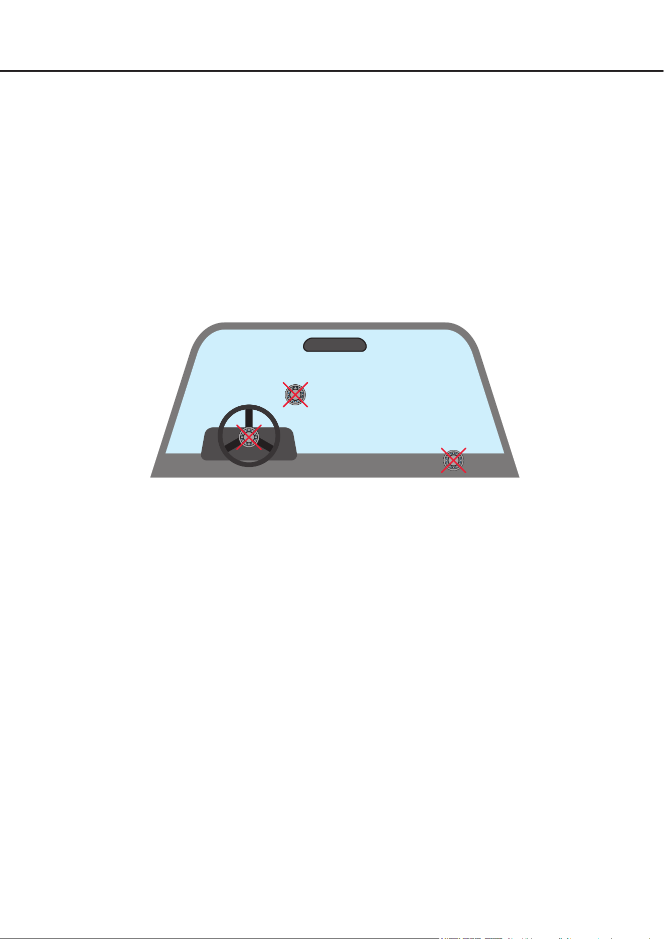
• Befestigen Sie den CONDUCTOR nicht in einer Abdeckung eines Airbags (bspw. Lenkrad, A-Säule oder Armaturen-
brett Beifahrerseite)
• Befestigen Sie die Bedieneinheit nicht im Sichtfeld des Fahrers
• Legen Sie den CONDUCTOR nicht unbefestigt auf dem Armaturenbrett ab
Bevor Sie den Lochausschnitt zur Befestigung anfertigen, vergewissern Sie sich, dass keine elektrischen Kabel und
Komponenten etc. dahinter verborgen sind. Diese könnten sonst beschädigt werden. Achten Sie bitte darauf, dass sich
solche Teile auch in einer doppelten Wandverkleidung verbergen können.
Die Kabelverbindungen müssen so verlegt sein, dass keine Klemm-, Quetsch- oder Bruchgefahr besteht. Bei scharfen
Kanten (Blechdurchführungen) müssen alle Kabel gegen Durchscheuern gepolstert sein. Ferner darf das Anschluss-
kabel niemals mit Zuleitungen zu Vorrichtungen des Kfz (Lüftermotoren, Brandkontrollmodulen, Benzinleitungen etc.)
verlegt werden.
5
2.Einbauhinweise&Installation
de
46
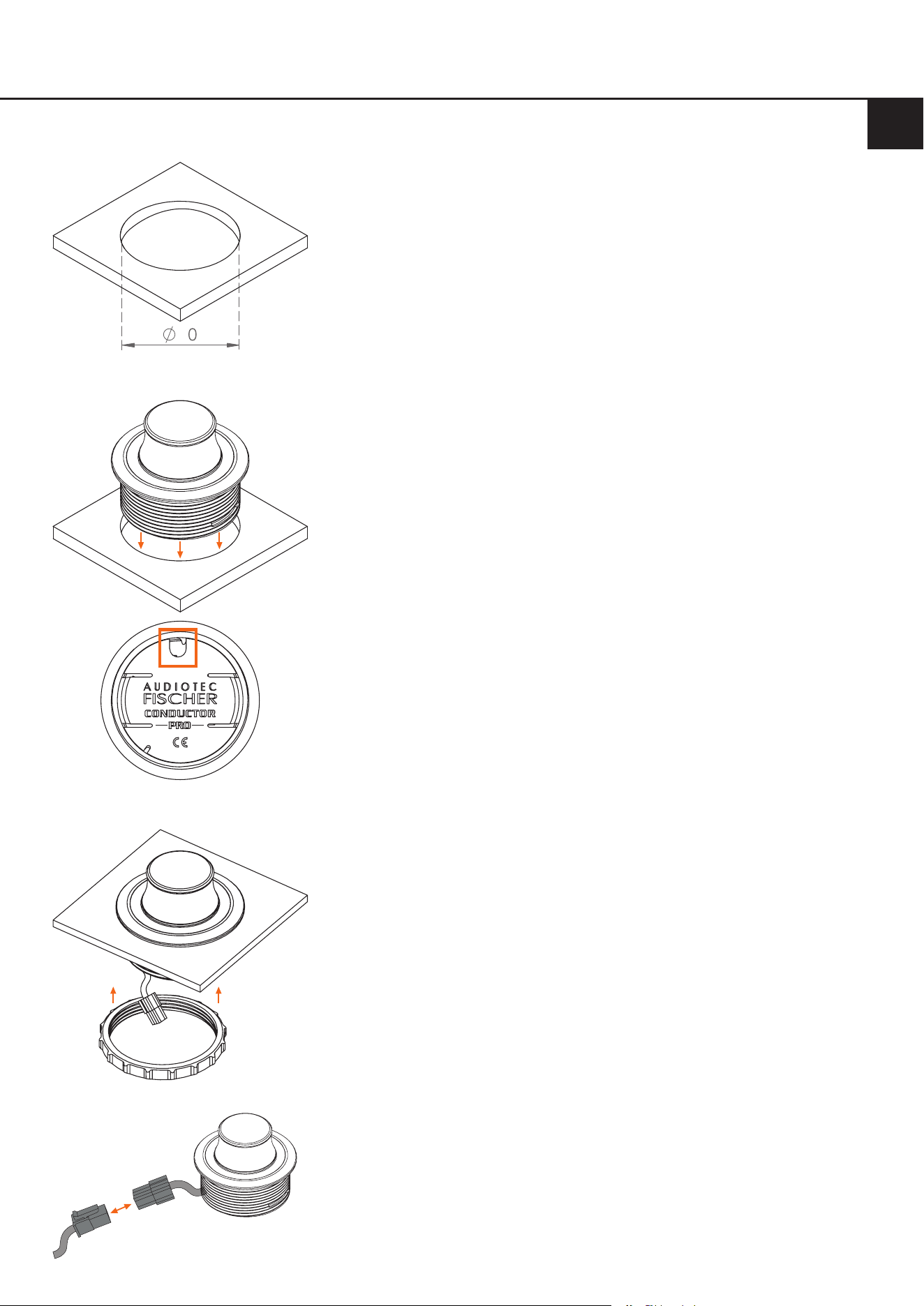
Lochausschnitt
i.
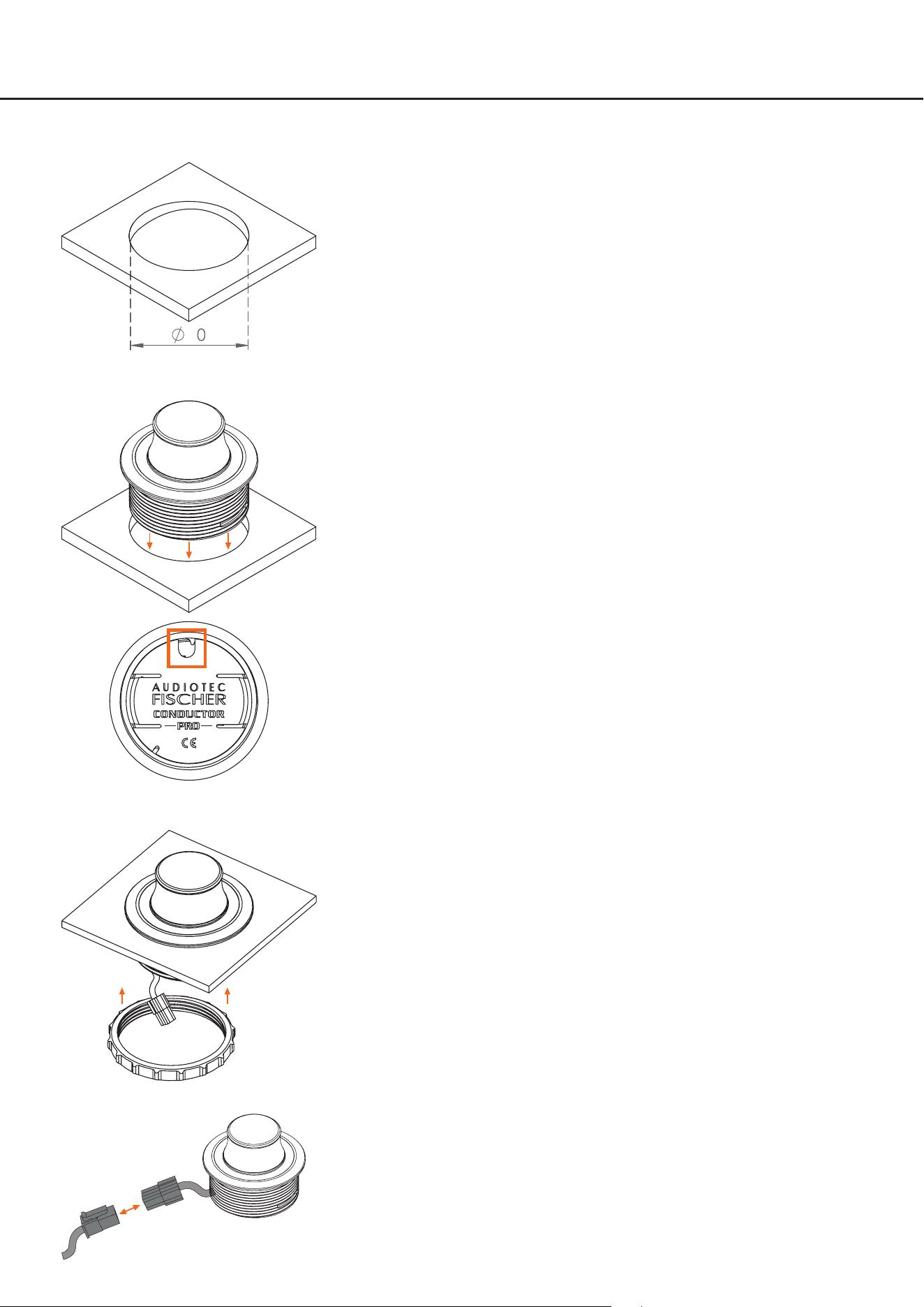
Lochausschnittanfertigen
Um eine sichere und fachgerechte Montage zu gewährleisten, darf der Loch-
ausschnitt nicht mehr als 40 mm betragen. Achten Sie darauf, dass der Platz
zwischen dem CONDUCTOR PRO und anderen Teilen, wie z.B. Schaltern,
Bedienelementen etc. ausreichend und genügend Einbautiefe vorhanden
ist. Dies ist besonders wichtig, wenn Einbauplätze ausgeschnitten werden
müssen. Vollständige Daten über die Einbautiefe und den Durchmesser des
CONDUCTOR PROs nden Sie in den technischen Daten dieser Anleitung.
Bitte stellen Sie sicher, dass die Auageäche möglichst plan und stabil ist.
CONDUCTOR PRO einsetzen
Setzen Sie das Gehäuse gleichmäßig in den Lochausschnitt.
WICHTIG: Um Beschädigungen zu vermeiden, drücken Sie zur Montage nie-
mals auf den Drehknopf in der Mitte des CONDUCTOR PROs, sondern aus-
schließlich auf dessen umliegendes Gehäuse.
Um den CONDUCTOR PRO korrekt auszurichten, orientieren Sie sich an der
Kabeldurchführung auf der Rückseite des Gehäuses (siehe dritte Abbildung
links).
Die Kabeldurchführung ist im eingebauten Zustand in der 12-Uhr-Position
auszurichten. Falls dies aufgrund der Einbausituation nicht realisierbar ist,
kann der CONDUCTOR PRO auch in 30°-Schritten gedreht eingebaut wer-
den. Die LED-Anzeige lässt sich anschließend in der DSP PC-Tool Software
an die Einbauposition anpassen (siehe Seite 14, „Installation orientation“).
CONDUCTORPROxieren
Sobald der CONDUCTOR PRO in seiner nalen Einbauposition sitzt und
das Aluminiumgehäuse plan auiegt, führen Sie das 20 cm CONDUCTOR
PRO-Kabel durch den Befestigungsring und schrauben diesen anschließend
auf das Gehäuse.
Ziehen Sie den Ring handfest an. Achten Sie darauf, ihn nicht zu fest anzu-
ziehen, um Beschädigungen am CONDUCTOR PRO oder an der Fahrzeug-
verkleidung zu vermeiden.
CONDUCTOR PRO-Anschlusskabel verlegen und anschließen
Verlegen Sie das 4,8 m lange Verbindungskabel und verbinden Sie es mit
dem 20 cm CONDUCTOR PRO-Kabel.
2.1 Montage des CONDUCTOR PROs
iii.
v.
ii.
CONDUCTOR-
Kabel
Verbindungs-
kabel
iv.
6
2.Einbauhinweise&Installation
46
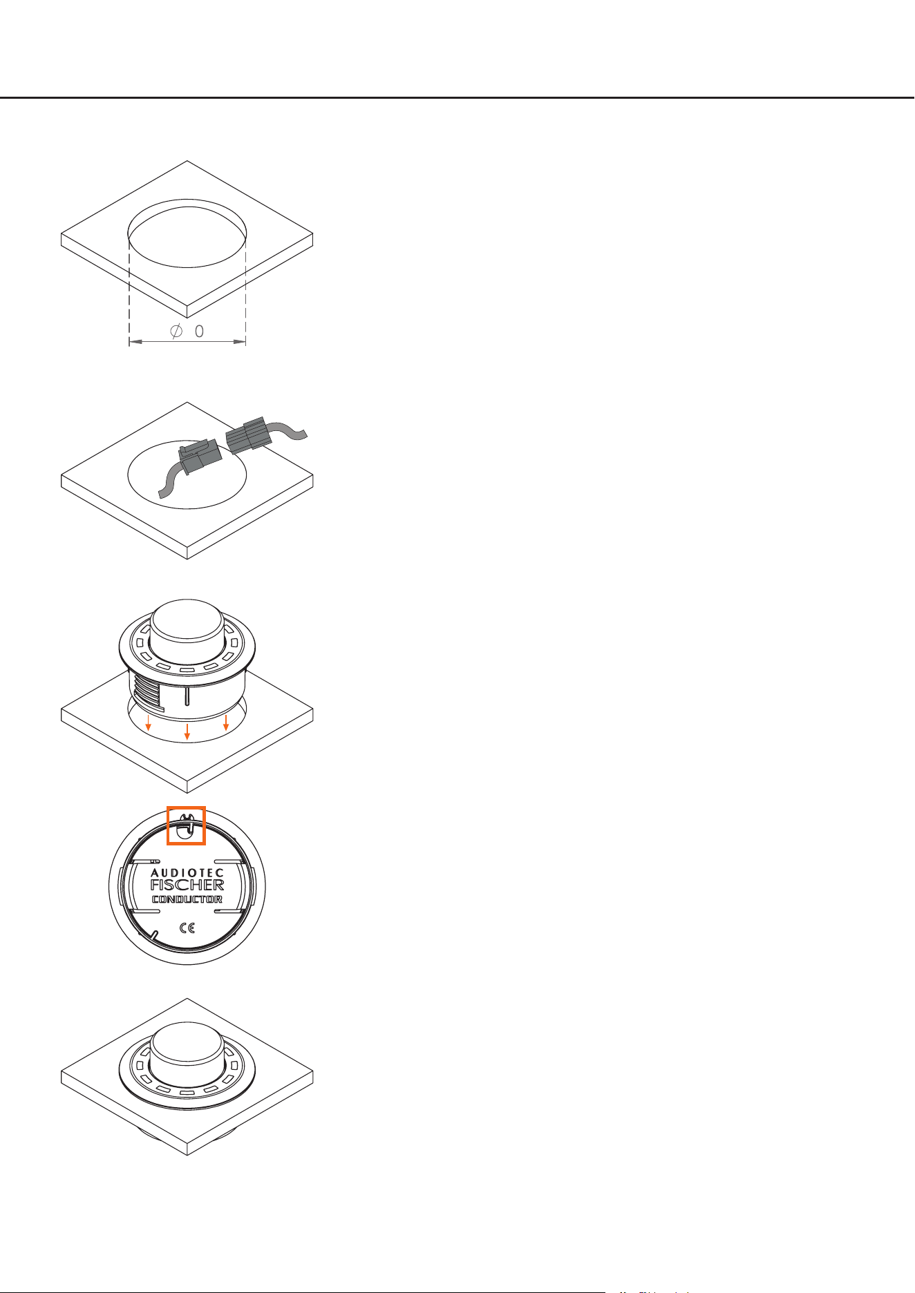
Lochausschnitt
i. Lochausschnittanfertigen
Um eine sichere und fachgerechte Montage zu gewährleisten, darf der
Lochausschnitt nicht mehr als 40 mm betragen. Achten Sie darauf, dass der
Platz zwischen dem CONDUCTOR und anderen Teilen, wie z.B. Schaltern,
Bedienelementen etc. ausreichend und genügend Einbautiefe vorhanden
ist. Dies ist besonders wichtig, wenn Einbauplätze ausgeschnitten werden
müssen. Vollständige Daten über die Einbautiefe und den Durchmesser des
CONDUCTORS nden Sie in den technischen Daten dieser Anleitung. Bitte
stellen Sie sicher, dass die Auageäche möglichst plan und stabil ist.
CONDUCTOR-Anschlusskabel verlegen und anschließen
Verlegen Sie das 4,8 m lange Verbindungskabel und führen dies von hin-
ten durch die Einbauönung. Anschließend verbinden Sie das Kabel mit dem
20 cm CONDUCTOR-Kabel.
CONDUCTOR einsetzen
Drücken Sie das Gehäuse gleichmäßig in den Lochausschnitt.
WICHTIG: Um Beschädigungen zu vermeiden, drücken Sie zur Montage
niemals auf den Aluminium Knopf in der Mitte des CONDUCTORs, sondern
ausschließlich auf dessen umliegendes Kunststo-Gehäuse.
Um den CONDUCTOR auszurichten, orientieren Sie sich an der 12 Uhr Mar-
kierung auf dem Gehäuse (siehe vierte Abbildung links).
Sollte es aufgrund der Einbausituation nicht möglich sein den CONDUCTOR
in der 12-Uhr Position einzubauen, kann dieser auch in 30°-Schritten ge-
dreht verbaut werden. Die LED-Anzeige kann anschließend in der DSP PC-
Tool Software der Einbauposition entsprechend angepasst werden (Siehe
Seite 14, „Installation orientation“).
Wenn Sie den CONDUCTOR in seine nale Einbauposition gebracht haben,
sollte das Kunststo-Gehäuse plan auiegen.
2.2 Montage des CONDUCTORs
iii.
v.
ii.
CONDUCTOR-
Kabel
Verbindungs-
kabel
iv.
7
2.Einbauhinweise&Installation
de
2.3 Anschluss des CONDUCTOR / PRO an einen DSP / DSP-Verstärker
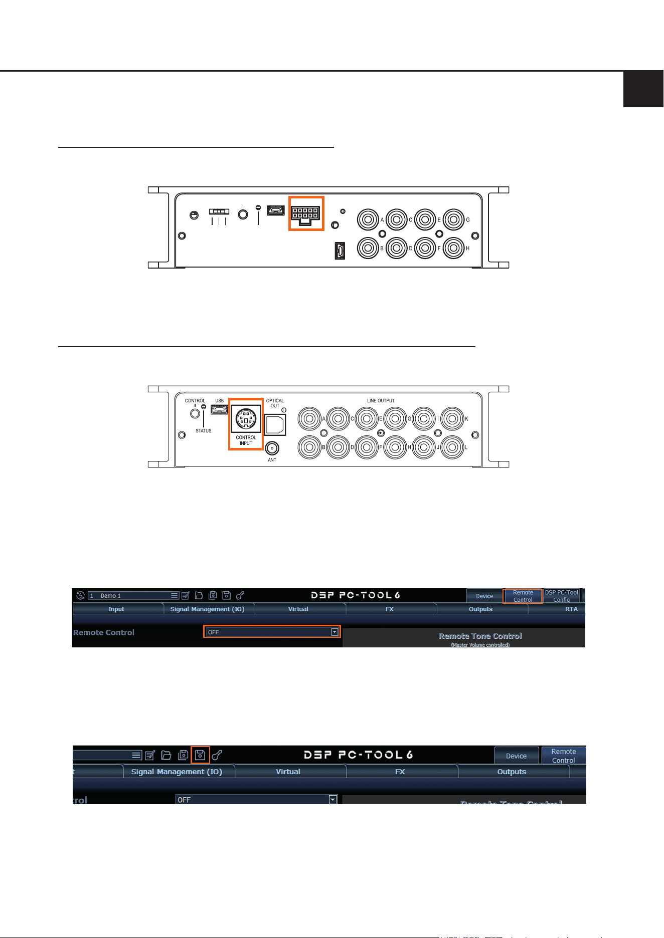
1. Verbinden Sie das Anschlusskabel des CONDUCTORs mit dem DSP / DSP Verstärker
1.1 DSP / DSP-Verstärker mit SCP (Smart Control Port)
Stecken Sie den SCP-Stecker des CONDUCTOR Verbindungskabels in den Multifunktionsanschluß (SCP) des
DSPs / DSP-Verstärkers.
USB-AUDIO
GND
ISO 200Ω
CONTROL
STATUS
USB LINE OUTPUT
SCP
Hinweis: Sofern Ihr CONDUCTOR keinen SCP-Stecker besitzt („for Control Input“ Variante), ist ein SCP-to-Control
Input Adapter (Art-Nr. M141313) optional bei Ihrem Fachhändler erhältlich.
1.2 DSP / DSP-Verstärker mit Control Input (nur bei CONDUCTOR für Control Input)
Ist ihr DSP-Produkt noch mit einem Control-Input ausgestattet, stecken Sie den Rundstecker des CONDUCTOR
Verbindungskabels in den Multifunktionsanschluß (Control Input) des DSPs / DSP-Verstärkers.
2. Schalten Sie Ihr Soundsystem ein und starten anschließend die DSP PC-Tool Software. Die Software nden Sie auf
www.audiotec-scher.de/dsp-pc-tool (Kompatibel ab DSP PC-Tool Software Version 5).
Der CONDUCTOR wird über den DSP mit Spannung versorgt und automatisch mit eingeschaltet.
3. Önen Sie das „Remote Control“-Menü (1) im DSP PC-Tool. Dort (2) können Sie nun den CONDUCTOR / PRO
auswählen (2) und so dessen Kongurationsmenü önen.
2
1
4. Nun können Sie weitere Einstellungen des CONDUCTOR vornehmen. Weitere Informationen zur Konguration
nden Sie auf Seite 13 ., „Konguration in der DSP PC-Tool Software“.
5. Um den Vorgang abzuschließen, speichern Sie die durchgeführten Einstellungen und die Aktivierung des
CONDUCTOR im DSP / DSP-Verstärker durch das Klicken auf den „Speichern“ Button im DSP PC-Tool.

8
3. Bedienung des CONDUCTOR / PROs
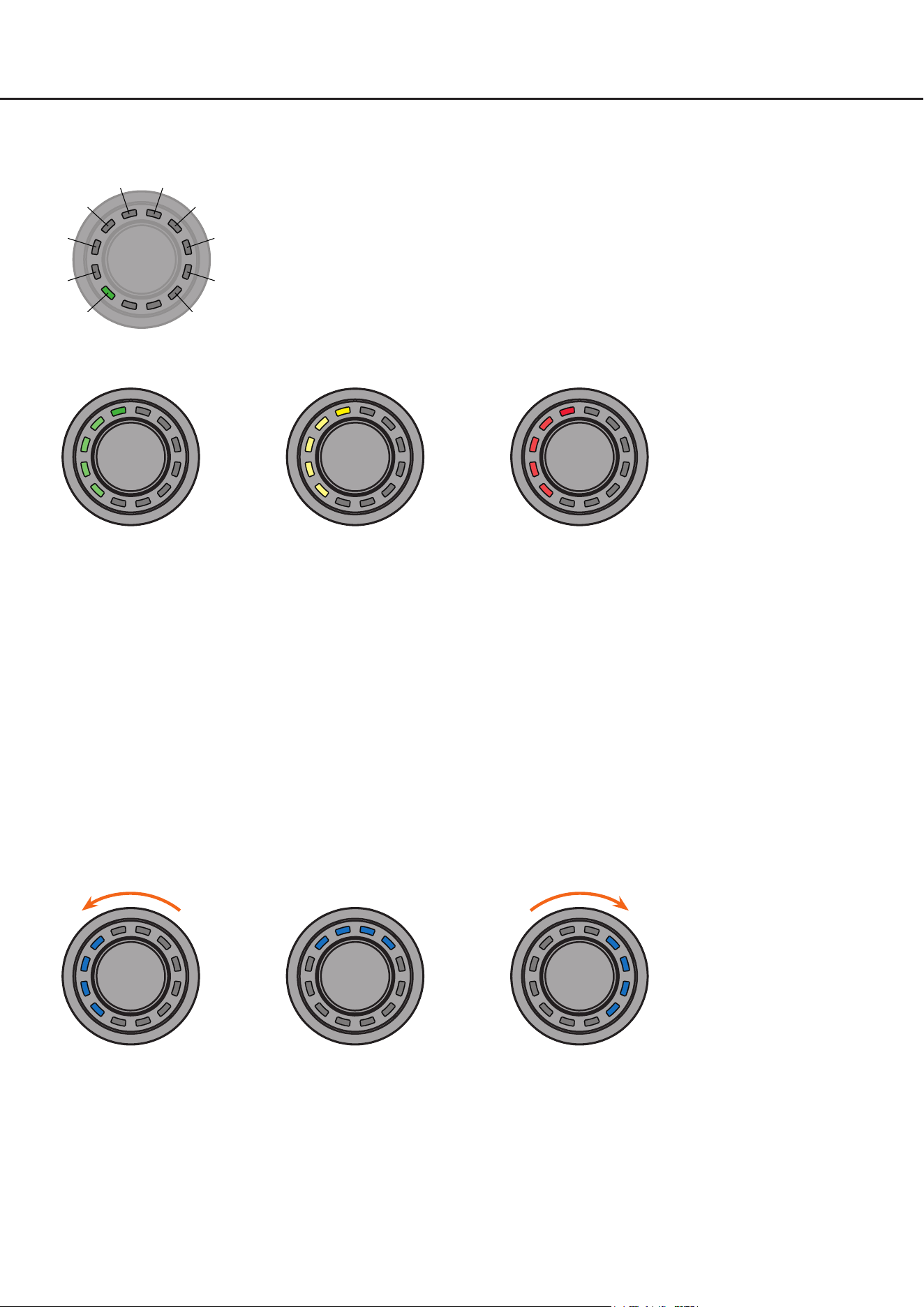
Die Bedienung des CONDUCTOR erfolgt durch Drehen und Drücken des Drehreglers. Die LED-Beleuchtung gibt dabei
Feedback zum ausgewählten Menü und der durchgeführten Aktion.
Drehregler
RGB-LED
Die verschiedenen Menüs können durch einen kurzen Tastendruck gewechselt werden. Die Regelung der jeweiligen
Lautstärke, bzw. die Auswahl der verfügbaren Menüoptionen, erfolgt durch Drehen des Drehreglers. Über einen langen
Tastendruck wird die jeweilige Auswahl bestätigt oder die ausgewählte Volume gemutet. Zudem kann bei verbautem
Bluetooth Modul (BT Extension Card) in jedem Volume Menü die „Nächster Titel“-Funktion durch einen Doppelklick
bzw. die „Vorheriger Titel“-Funktion über einen Dreifachklick aktiviert werden. Weitere Informationen zum Funktionsum-
fang und dem LED-Feedback eines Menüs nden Sie auf den nachfolgenden Seiten.
Hinweis: Ist ein Menü oder eine Volume im DSP PC-Tool nicht aktiviert, wird das nächste aktive Menü oder aktive
Volume angewählt.
9
* Nur bei Geräten mit optional verbauter Extension Card BT
Volume 1
Drehen: Lautstärke regeln
Lang drücken: Mute / Demute
2 x kurz drücken: Nächster Titel*
3 x kurz drücken: Vorheriger Titel*
Extra lang drücken (5 Sek.): Bluetooth Pairing starten*
Volume 2
Drehen: Lautstärke regeln
Lang drücken: Mute / Demute
2 x kurz drücken: Nächster Titel*
3 x kurz drücken: Vorheriger Titel*
Extra lang drücken (5 Sek.): Bluetooth Pairing starten*
Volume 3
Drehen: Lautstärke regeln
Lang drücken: Mute / Demute
2 x kurz drücken: Nächster Titel*
3 x kurz drücken: Vorheriger Titel*
Extra lang drücken (5 Sek.): Bluetooth Pairing starten*
Volume 4
Drehen: Lautstärke regeln
Lang drücken: Mute / Demute
2 x kurz drücken: Nächster Titel*
3 x kurz drücken: Vorheriger Titel*
Extra lang drücken (5 Sek.): Bluetooth Pairing starten*
Sound Setup selection
Drehen: Sound Setup wählen
Lang drücken: Sound Setup aktivieren
Farben: Grün (Aktiv), Gelb (Inaktiv), Rot (nicht vorhanden)
ToneControl
Drehen: ToneControl Gain regeln
Lang drücken: ToneControl Frequenzbereich wechseln
Farben: Lila (Low Frequency), Gelb (High Frequency)
Bluetooth Playback Control*
Lang drücken: Play / Pause
Linksdrehung: Titel zurück
Rechtsdrehung: Titel vor
Extra lang drücken (5 Sek.): Bluetooth Pairing starten
1 x kurz drücken
1 x kurz drücken
1 x kurz drücken
1 x kurz drücken
1 x kurz drücken
1 x kurz drücken
1 x kurz drücken
de
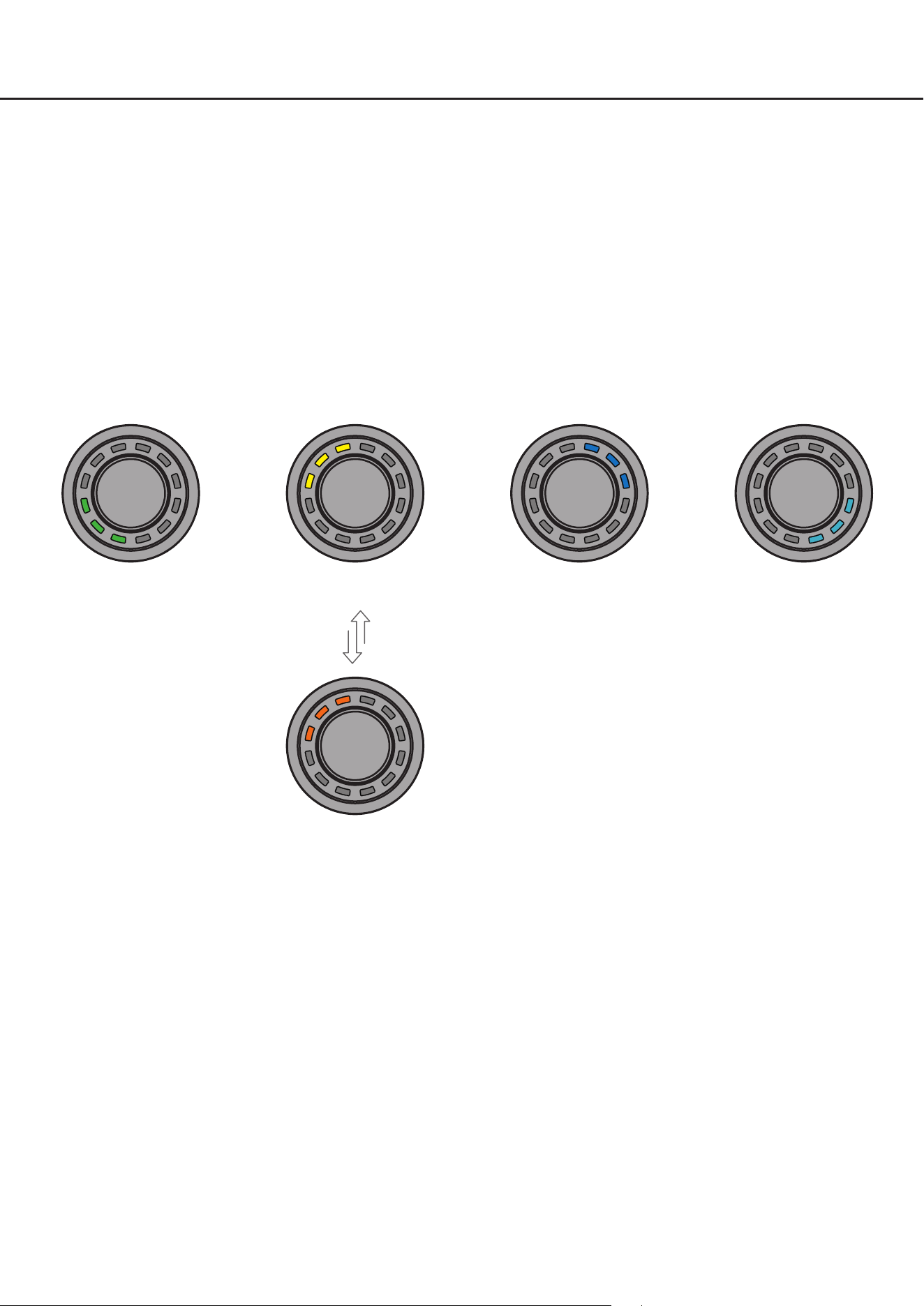
Signal Input selection
Drehen: Signaleingang wählen
Lang drücken: Signaleingang aktivieren
Farben: Grün (Main), Gelb (Optical Digital Input),
Blau (HEC1), Türkis (HEC2)
Aktivierung des Koaxialeingangs
Optischer Digitaleingang (gelb) aktiviert
Lang drücken für Umschaltung
zwischen optischem und koaxialen
Eingang (orange)
1 x kurz drücken
Hinweis: Die Menüführung ist zyklisch. Die Menüfolge beginnt im voreingestellten Menü.
10
3.1VolumeControlConguration(Lautstärkemenü1-4)
Mit Hilfe der vier Lautstärkemenüs ist eine separate Regelung von bis zu 4 unterschiedlichen Lautstärken (Master-,
Digital-, HEC/AUX-, Subwoofer-Lautstärke, Rear Attenuation etc.) möglich. Diese können wie unter Punkt 4.2 „Volume
Control Conguration“ auf Seite 14 festgelegt werden.
Die Lautstärke-Menüs werden nach einem Neustart des Systems mit den zuletzt eingestellten Werten wiederherge-
stellt. Sofern die „Startup Volume“ Option (siehe Seite 15, Punkt 4.2.5) konguriert wurde, wird die Lautstärke mit dem
maximal eingestellten Limit-Pegel wieder eingeschaltet, sofern dieser beim Ausschalten überschritten wurde.
Wird eine Volume komplett runtergeregelt, wird unabhängig vom eingestellten Regelumfang die Volume gemutet.
Aktionen:
Drehen: Lautstärkepegel einstellen
Lang drücken: Mute / De-Mute
2 x kurz drücken: Titel vor*
3 x kurz drücken: Titel zurück*
Extra lang drücken (5 Sek.): Bluetooth Pairing starten*
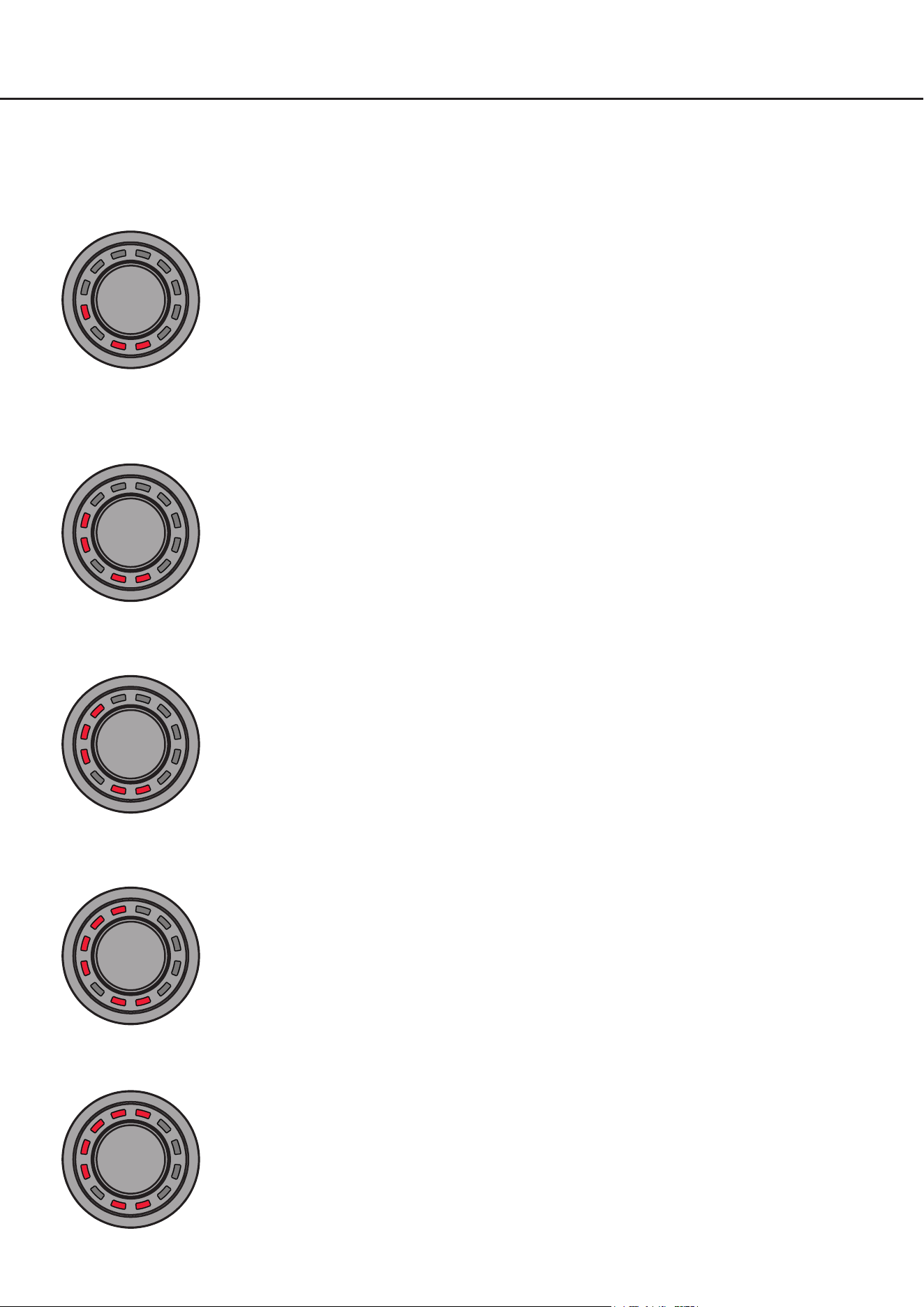
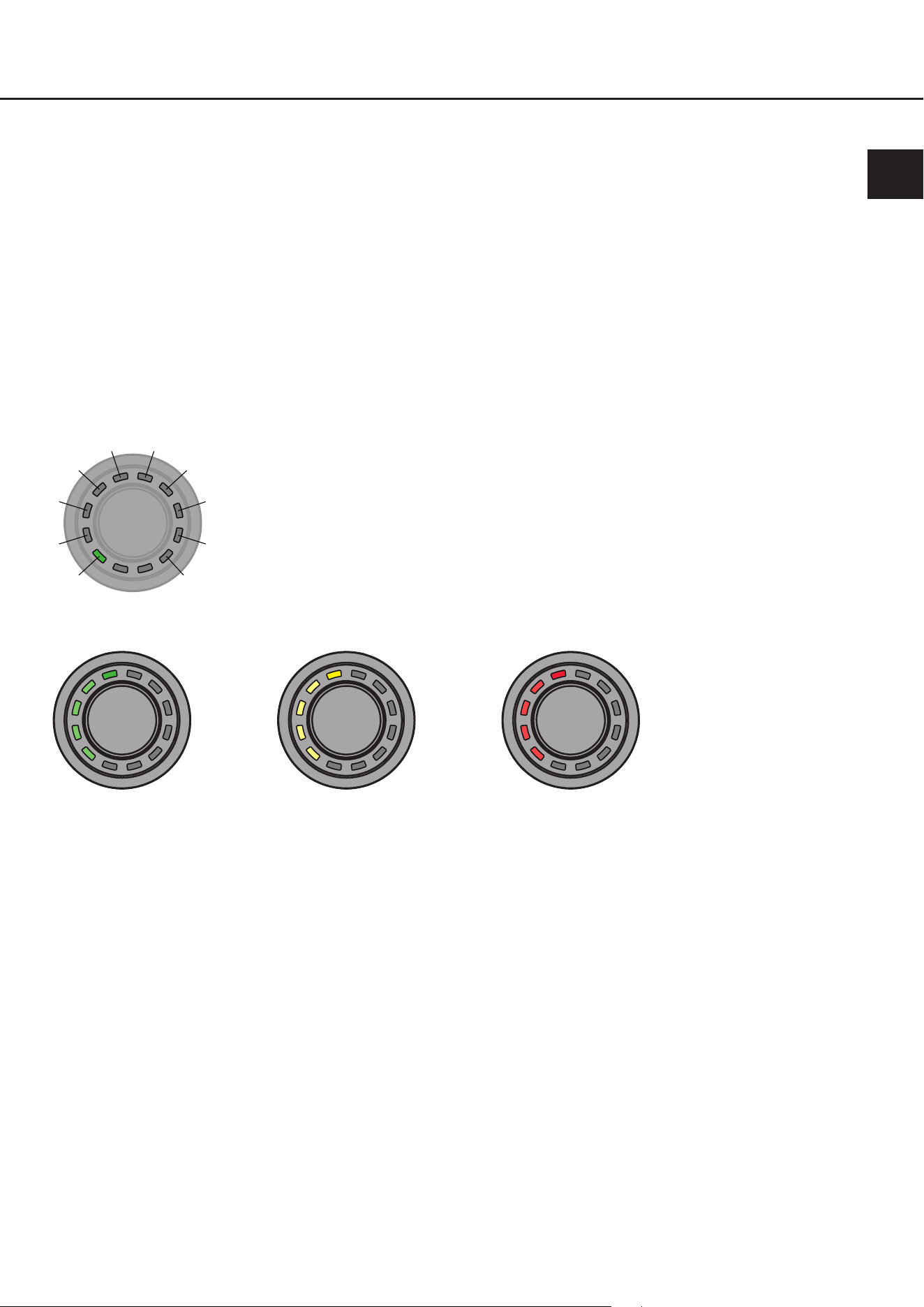
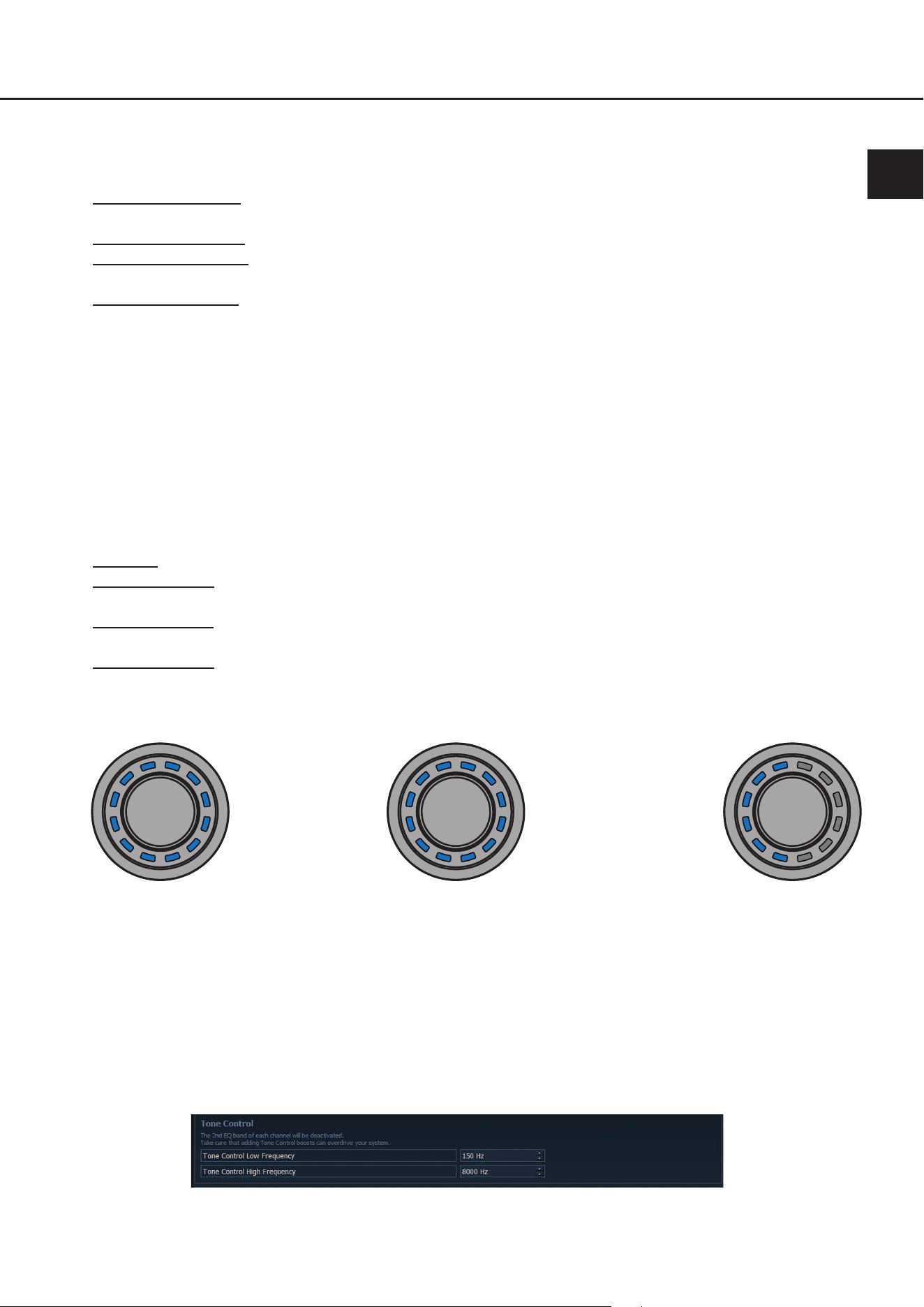
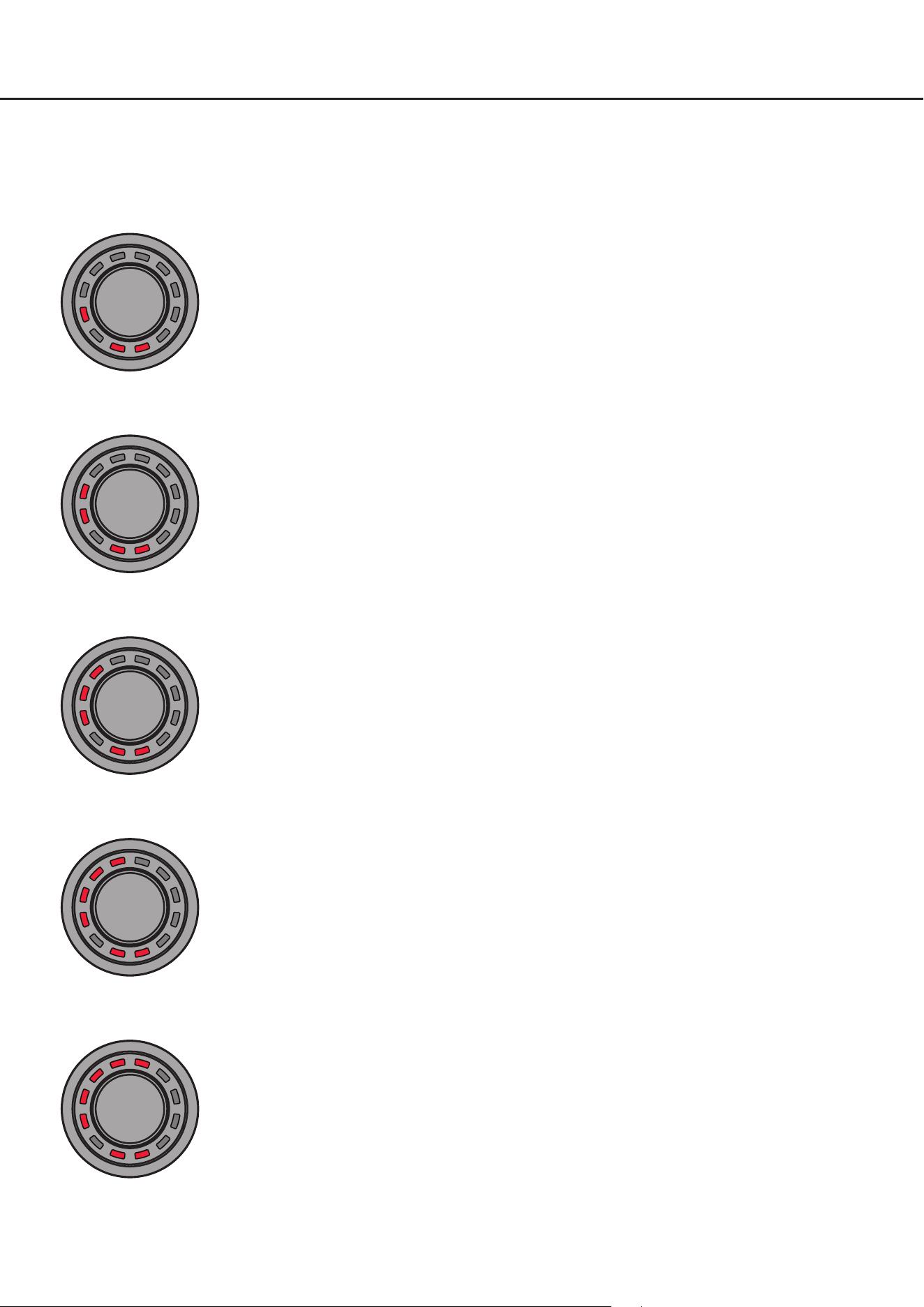
LED-Feedback:
Der eingestellte Lautstärkepegel wird von der linken unteren LED im Uhrzeigersinn verlaufend in der für die Volume
zugewiesenen Farbe angezeigt. Der Mute (lang drücken) wird durch eine einzelne, rotierende LED signalisiert.
Wird die Lautstärke im gemuteten Zustand geregelt, wird die Stumschaltung aufgehoben.
Minimal-Lautstärke Maximal-Lautstärke½ Lautstärke
3.2 ToneControl menu
Das ToneControl-Menü ermöglicht eine Klanganpassung über einen High- und Low-Shelf-Filter. Die Lautstärke kann
dabei im Bereich von -6 dB bis +6 dB verändert werden, sodass Höhen und Tiefen gezielt angehoben oder abgesenkt
werden können.
Die Frequenzen für den High- und Low-Shelf Filter können individuell in der DSP PC-Tool Software ( siehe Seite 16,
Punkt 4.3) deniert werden.
Aktionen:
Drehen: ToneControl Gain regeln
Lang drücken: ToneControl Frequenzbereiche wechseln (High Frequency / Low Frequency)
LED-Feedback:
Lila: Low Frequency
Gelb: High Frequency
0 dB +6 dB-6 dB
* Nur bei Geräten mit optional verbauter Extension Card BT
3. Bedienung des CONDUCTOR / PROs
11
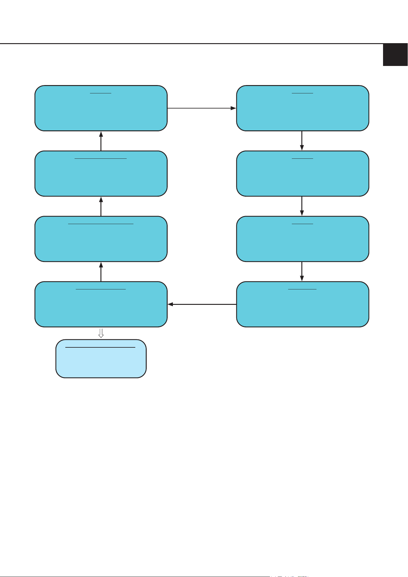
3.3 Signal Input selection menu(Signalquellenauswahlmenü)
Mit Hilfe des „Signal Input selection“ Menüs kann zwischen den am DSP / DSP-Verstärker angeschlossenen Signal-
quellen umgeschaltet werden. Das Menü startet mit dem aktuell ausgewählten bzw. zuletzt aktiven Eingang.
Aktionen:
Drehen: Signaleingang wählen
Lang drücken: Signaleingang aktivieren
LED-Feedback:
Grün: Main Input
Gelb: Optischer Digitaleingang (Optical Input)
Orange: Koaxialer Digitaleingang (Coax Input / Eingang nur über aktivierten, optischen Digitaleingang anwähl-
bar / siehe unten)
Blau: Extension Card 1 (HEC1)
Türkis: Extension Card 2 (HEC2 – nur BRAX DSP)
Main Input Digital Input
optisch
HEC1 HEC2
Digital Input
koaxial
Bei aktiviertem Digitaleingang
lange drücken um zwischen
optischem und koaxialem
Eingang umzuschalten
Hinweis: Der CONDUCTOR erkennt die Signaleingänge des angeschlossenen DSP / DSP-Verstärkers automatisch.
Es können ausschließlich die vorhandenen Signaleingänge angewählt werden. Alle anderen Eingänge werden nicht
per LED-Feedback angezeigt und sind auch nicht anwählbar.
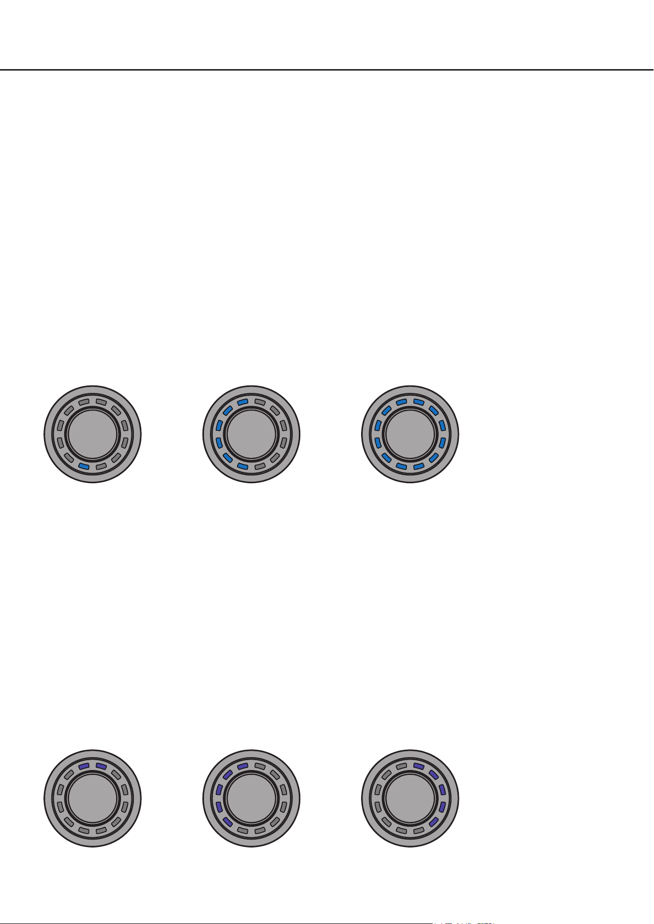
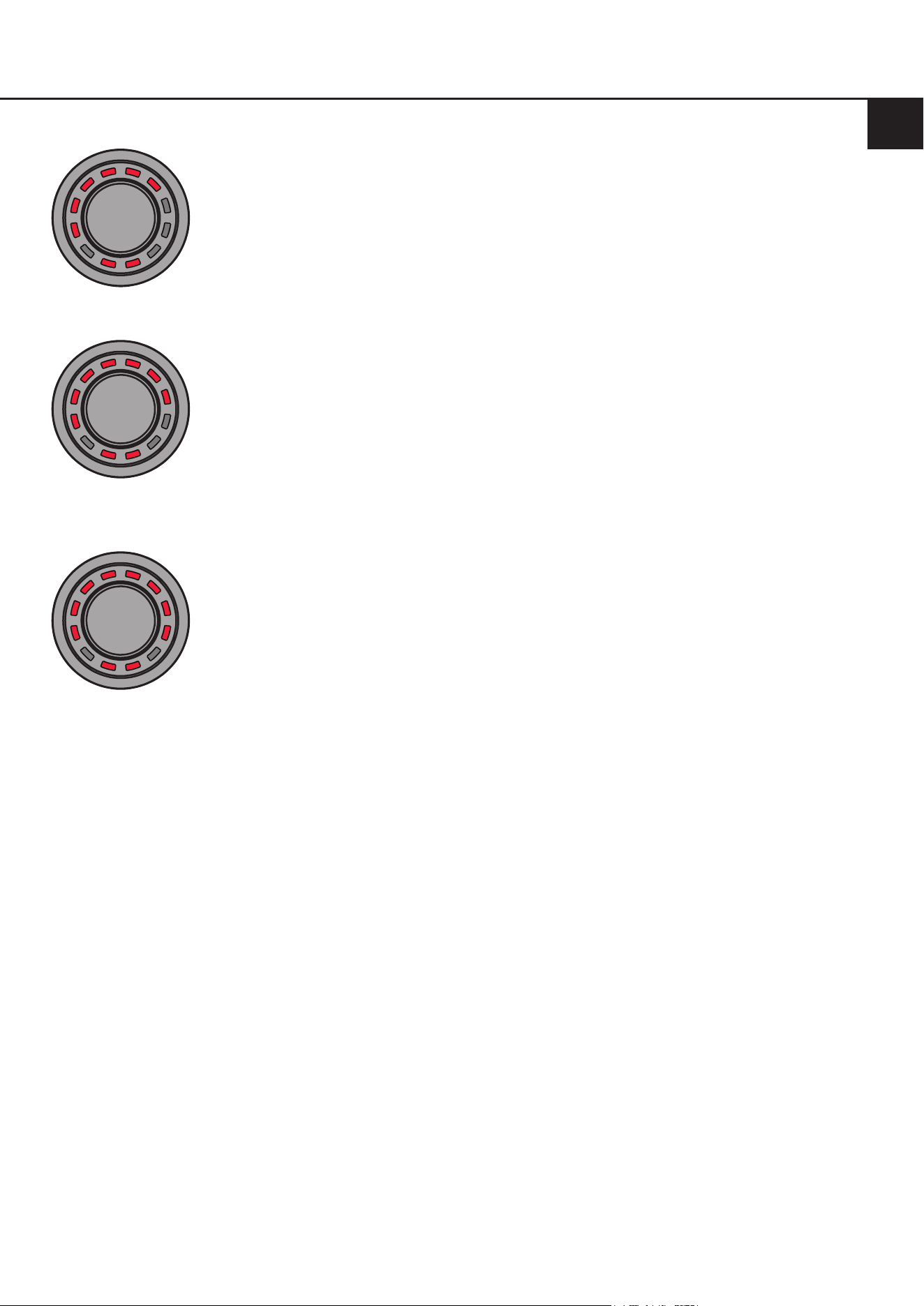
3.4SoundSetupselectionmenu(SoundSetup-Auswahlmenü)
Mit Hilfe des „Sound Setup selection“ Menüs lässt sich zwischen den bis zu 10 Sound Setups des DSPs umschalten.
Das Menü startet mit dem aktuell ausgewählten bzw. zuletzt aktiven Sound Setup.
Aktionen:
Drehen: Sound Setup wählen
Lang drücken: Sound Setup aktivieren
LED-Feedback:
Grün: Sound Setup aktiv
Gelb: Sound Setup Speicherplatz belegt, Setup inaktiv
Rot: Sound Setup Speicherplatz leer, kann nicht ausgewählt werden
de
12
Mit dem CONDUCTOR können die 10 Sound Setup Speicherplätze des DSPs angewählt und aktiviert werden. Die
Speicherplätze werden wie folgt angezeigt:
1
2
3
4
5 6
7
8
9
10
Beispiele für das LED-Feedback im „Sound Setup selection“ Menü:
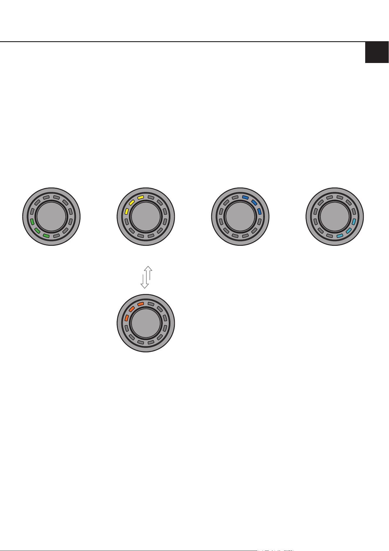
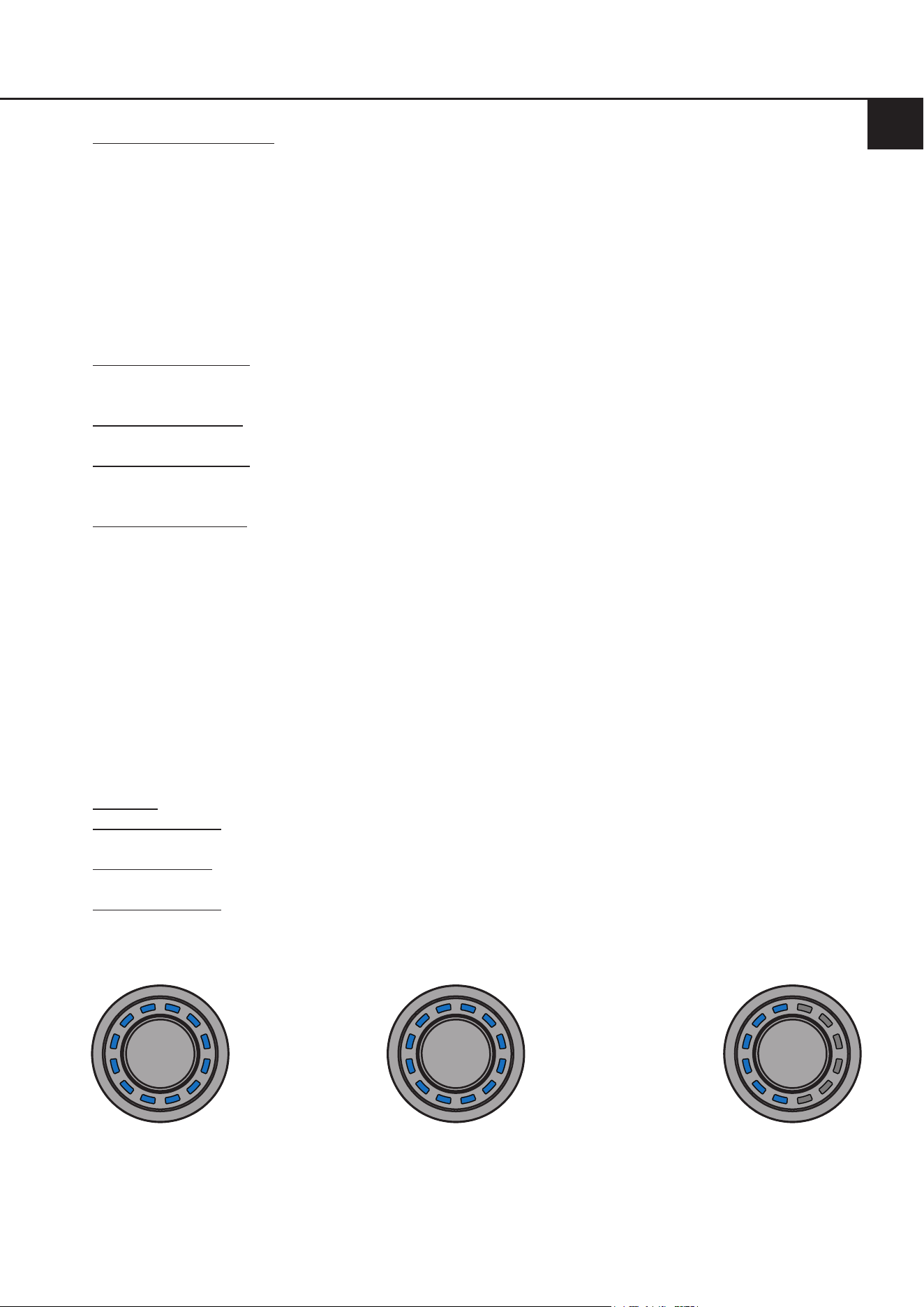
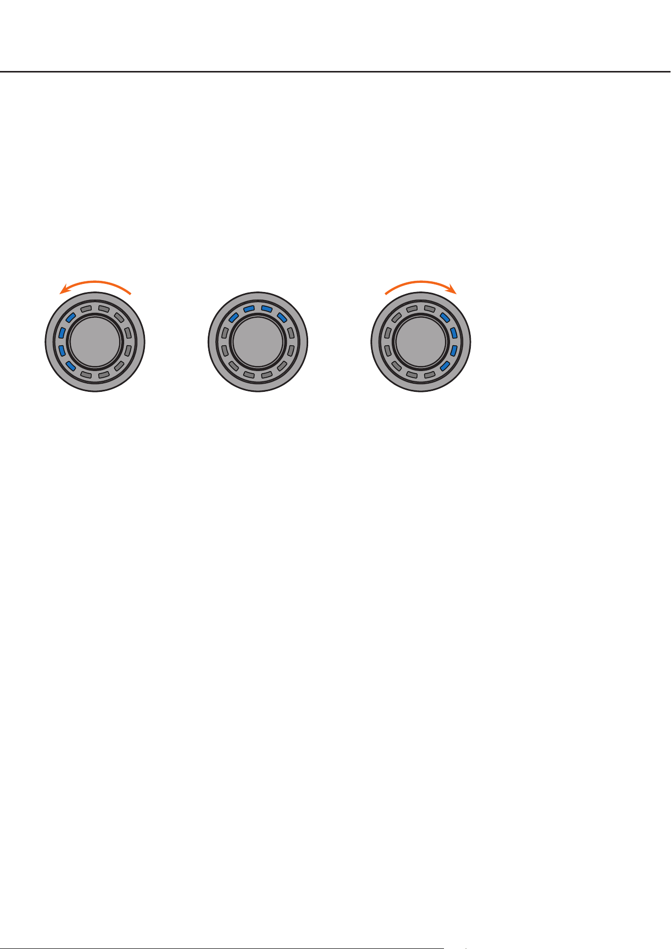
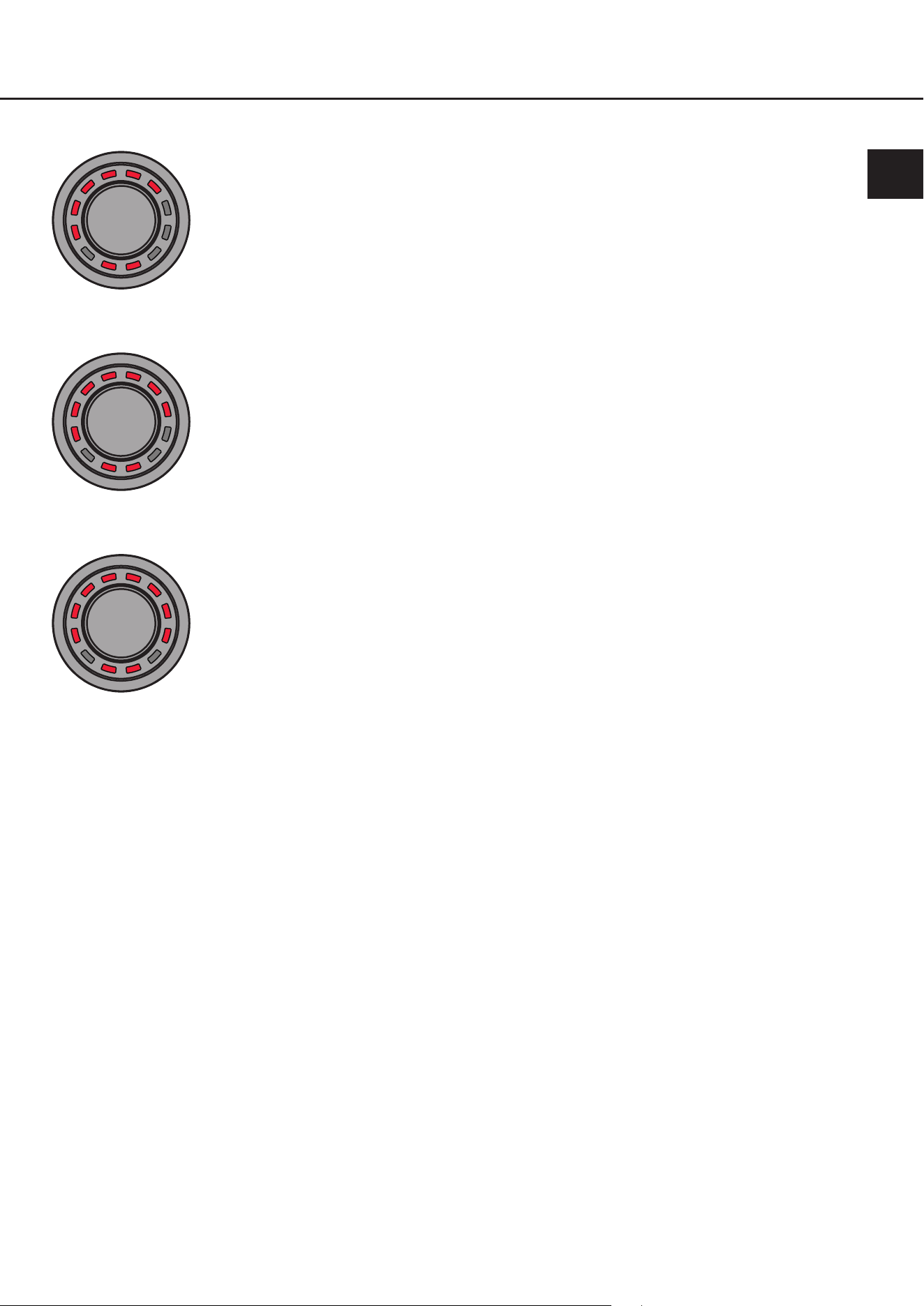
3.5BluetoothPlaybackControlmenu(BluetoothWiedergabesteuerungsmenü)*
Das „Bluetooth Playback Control“ Menü ermöglicht die Steuerung eines optional verbauten Bluetooth-Moduls (Play/
Pause, Track vor/zurück, Aktivierung des Pairing-Modus). Das Menü startet immer mit der Play / Pause Funktion (vier
LEDs oben an).
Aktionen:
Drehen: Aktion automatisch ausführen
Linksdrehung: Gegen den Uhrzeigersinn: Titel zurück
Rechtsdrehung: Im Uhrzeigersinn: Titel vor
Lang drücken: Play / Pause
Extra lang drücken (5 Sek.): Bluetooth Pairing starten
LED-Feedback:
Track zurück Play / Pause per langem
Tastendruck
Track vor
Sound Setup Nr. 5
aktiviert
Sound Setup Nr. 5 nicht
belegt und auch nicht
auswählbar
Sound Setup Nr. 5
verfügbar – kann durch
einen langen Tasten-
druck aktiviert werden
* Nur bei Geräten mit optional verbauter Extension Card BT
3. Bedienung des CONDUCTOR / PROs
13
4.KongurationinderDSPPC-ToolSoftware
Hinweis: Die nachfolgende Konguration wird anhand der DSP PC-Tool Software Version 6 beschrieben;
bei älteren Versionen können Menüstruktur und Bezeichnungen abweichen.
ÜbersichtKongurationsmenü
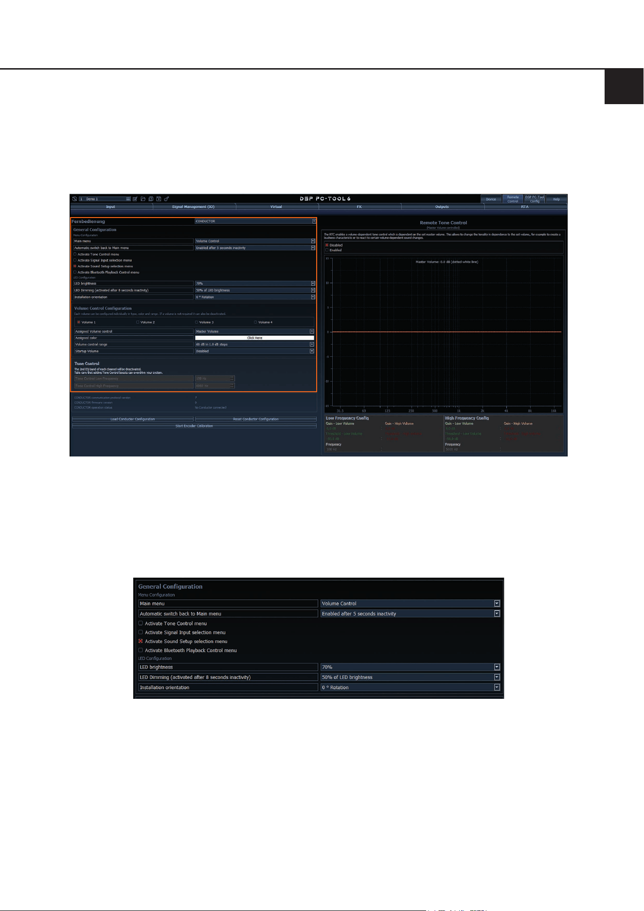
Das Kongurationsmenü bendet sich im „Remote Control“-Menü der DSP PC-Tool Software. Das Menü ist jedoch nur
sichtbar, wenn Sie den CONDUCTOR / PRO wie auf Seite 7 beschrieben angewählt haben.
Im Kongurationsmenü werden sämtliche Einstellungen des CONDUCTOR / PROs vorgenommen.
Das Menü ist unterteilt in den „General Conguration“-, „Volume Control Conguration“- und Status-Bereich.
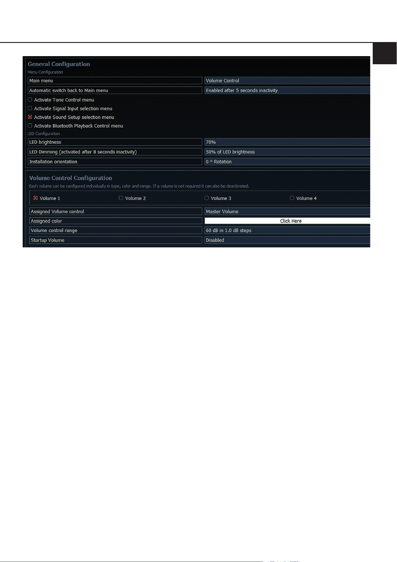
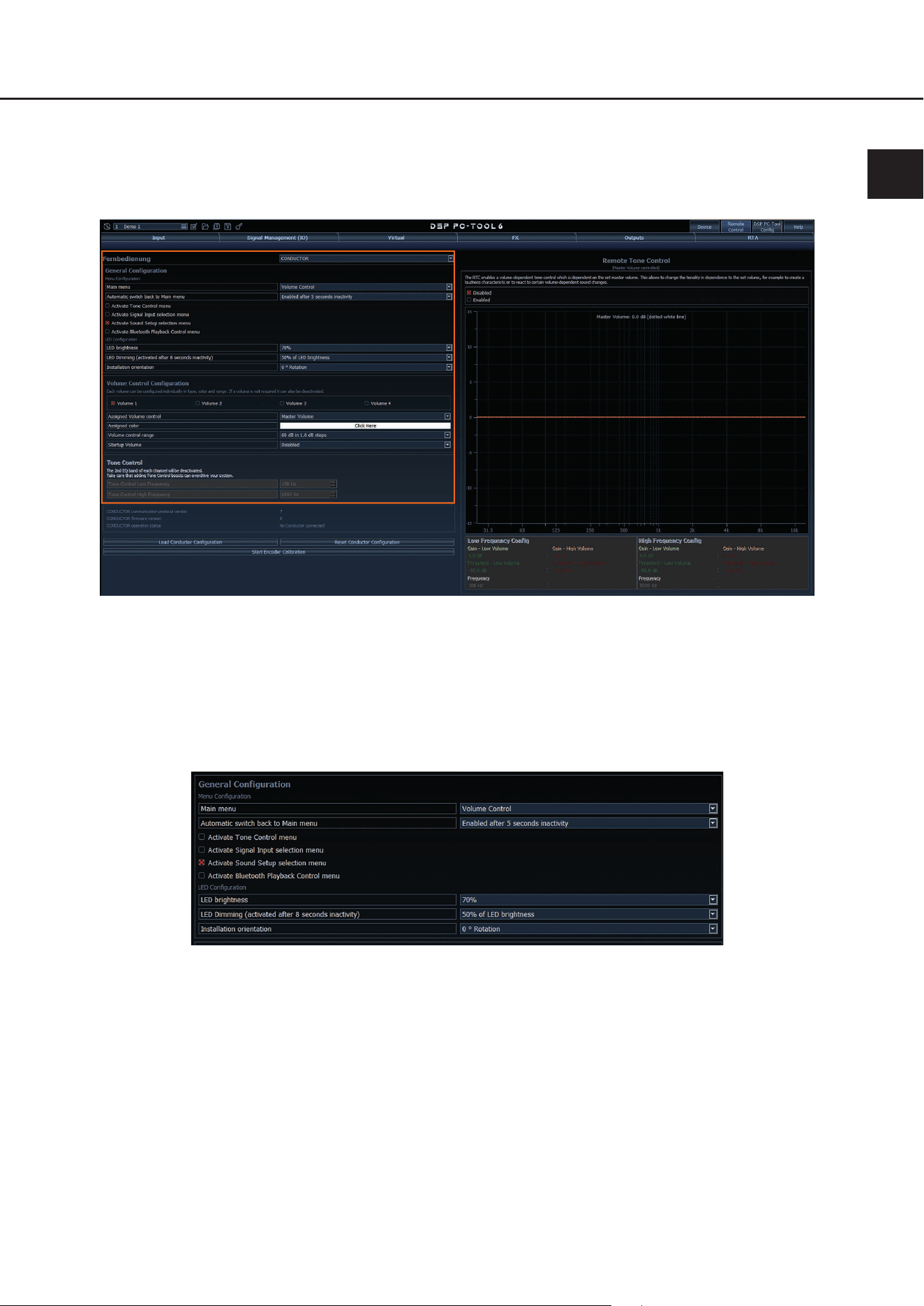
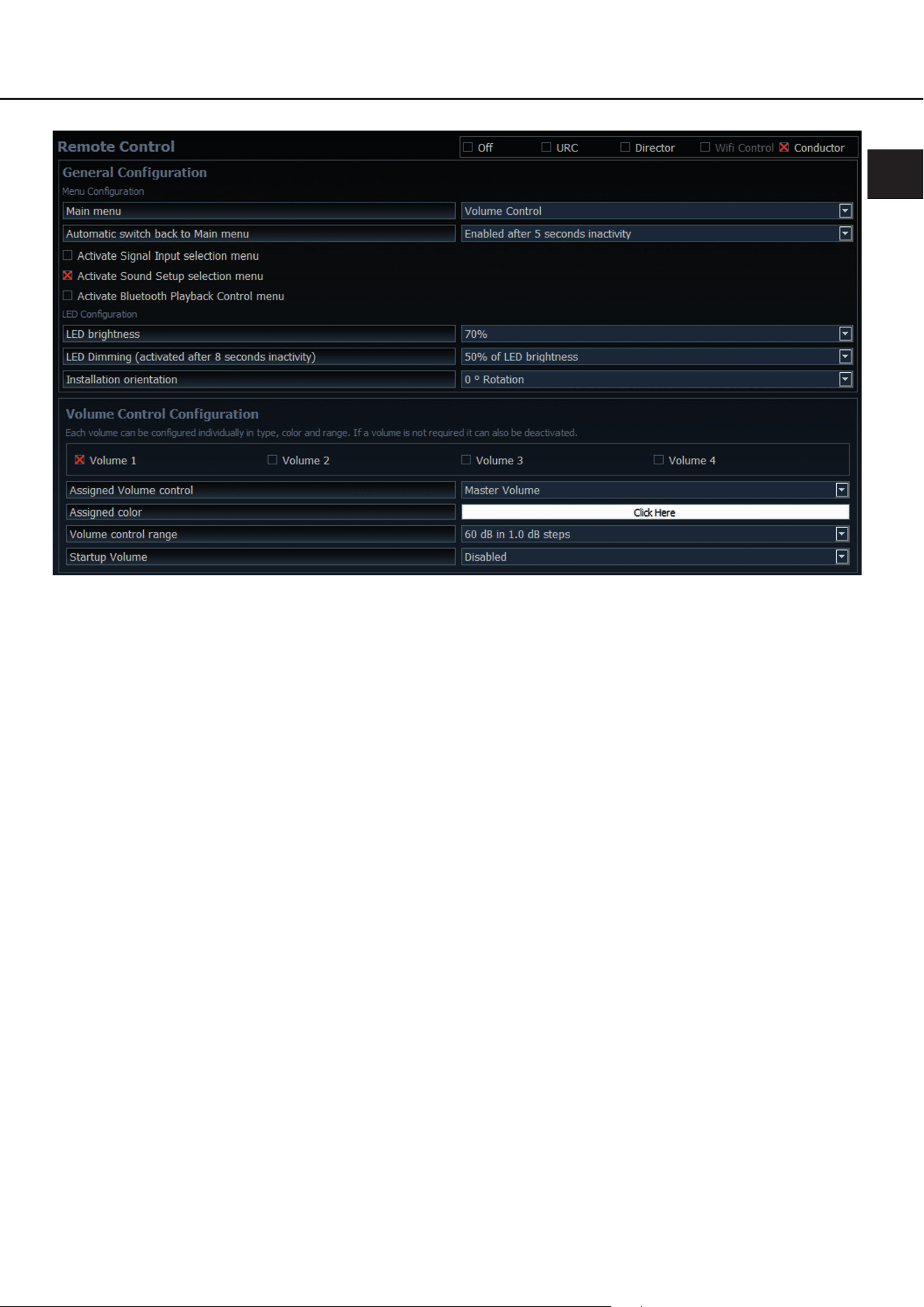
4.1GeneralConguration(AllgemeineKonguration)
In der „General Conguration“ werden alle grundlegenden Einstellungen der Menü-Konguration (Menu Conguration)
sowie die LED-Display Einstellungen (LED Conguration) vorgenommen.
4.1.1Mainmenu(Hauptmenü)
An dieser Stelle wird das Startmenü des CONDUCTOR festgelegt, welches direkt nach dem Einschalten des
DSPs aufgerufen wird.
Zur Auswahl stehen das Volume Control-, Signal Input selection-, Sound Setup selection- und Bluetooth Playback
Control-Menü.
4.1.2AutomaticswitchbacktoMainmenu(AutomatischeUmschaltungzumHauptmenü)
Ist die Funktion aktiviert (Enabled after 5 seconds inactivity) schaltet der CONDUCTOR nach ca. 5 Sekunden
auf das eingestellte „Main menu“ zurück, sofern zuvor ein anderes Menü angewählt wurde. Ist die Funktion aus-
geschaltet (Disabled) bleibt das derzeit angewählte Menü so lange ausgewählt, bis dieses durch einen kurzen
Tastendruck manuell gewechselt wird.
de
14
4.1.3Menü-Aktivierung
An dieser Stelle können neben den Lautstärkestellern auch weitere Menüs aktiviert bzw. deaktiviert werden. So-
fern ein Menü deaktiviert ist, kann dieses nicht über den CONDUCTOR angewählt werden.
Hinweis: Das „Volume Menu“ ist immer aktiviert und kann nur durch die Deaktivierung aller vier Volumes in der
„Volume Control Conguration“ ausgeschaltet werden (siehe Punkt 4.2).
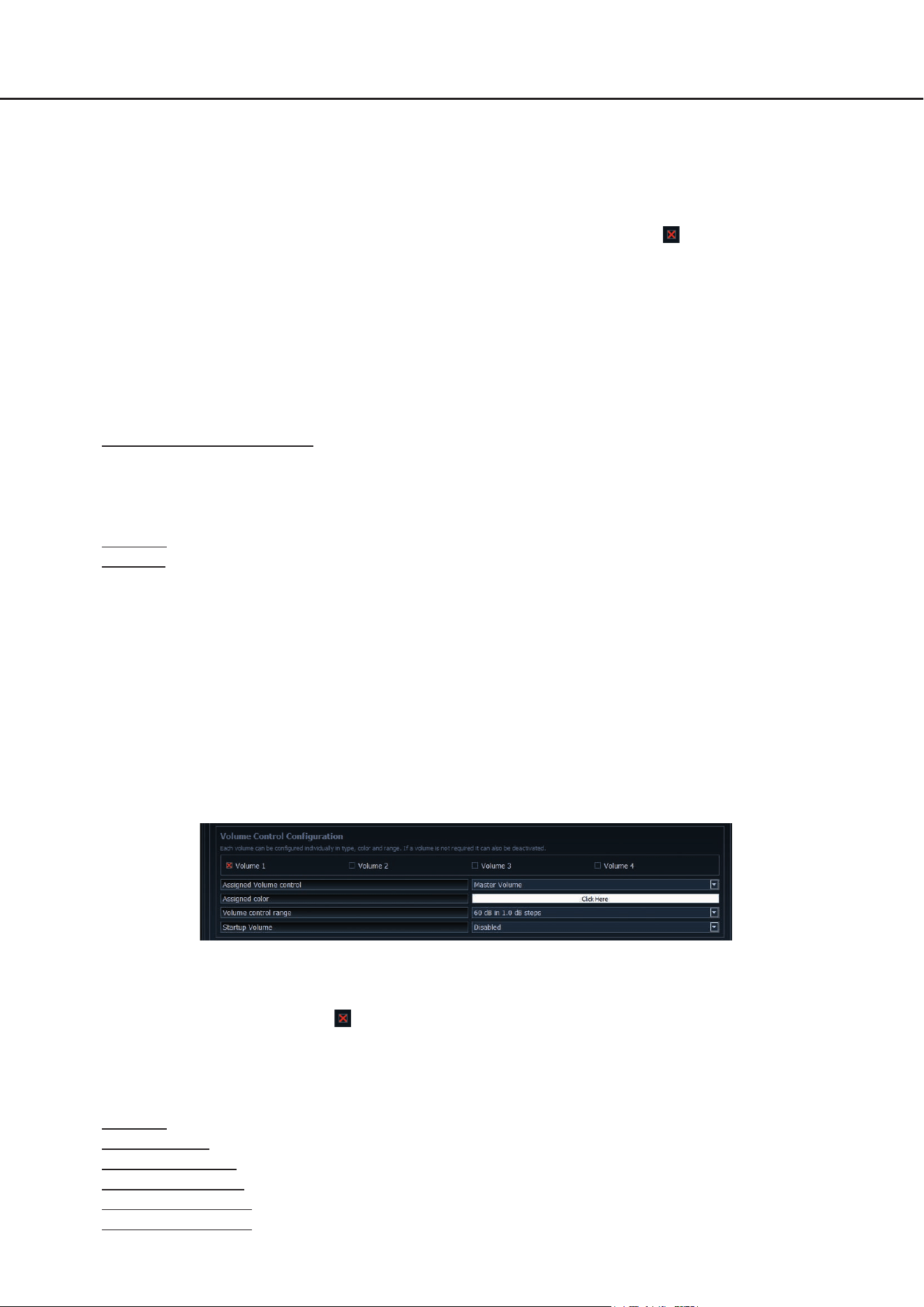
Ein aktiviertes Menü ist an einem roten Kreuz vor dem Menünamen zu erkennen.
Hinweis: Das im „Main menu“ eingestellte Startmenü wird automatisch aktiviert.
4.1.4LEDbrightness(LED-Helligkeit)
Hier kann die Helligkeit der LED-Beleuchtung eingestellt werden. Standardmäßig ist diese auf 70 % eingestellt.
4.1.5LEDDimming(LED-Dimmung)
In diesem Menü kann eine optionale Dimmung der LEDs konguriert werden. Bei Aktivierung dieser Funktion
werden die LEDs nach 8 Sekunden Inaktivität automatisch um den kongurierten Wert abgedunkelt oder ganz
ausgeschaltet.
5 % - 75 % of LED brightness: Die LEDs werden, ausgehend von der eingestellten LED-Helligkeit, um den ein-
gestellten Prozentbereich gedimmt. Standardmäßig ist eine Dimmung von 50 % eingestellt. Der Auswahlbereich
kann je nach eingestellter Helligkeit der LED-Beleuchtung (LED brightness) beschränkt werden.
Beispiel: LED brightness 50 %, LED Dimming 50 %
Die eingestellte LED-Helligkeit von 50 % wird nun noch einmal um 50 % abgedimmt.
Disabled: Schaltet das „LED Dimming“ aus.
LEDs o: Schaltet die LED-Beleuchtung komplett ab.
4.1.6Installationorientation(AnpassungandieEinbauposition)
Sollte es aufgrund der Einbausituation nicht möglich sein den CONDUCTOR in der 12-Uhr Position einzubau-
en, kann dieser auch in 30°-Schritten gedreht verbaut werden. Die LED-Anzeige kann anschließend in der
DSP PC-Tool Software der Einbauposition entsprechend angepasst werden ( siehe Seite 5 - 6, Montage des
CONDUCTORs).
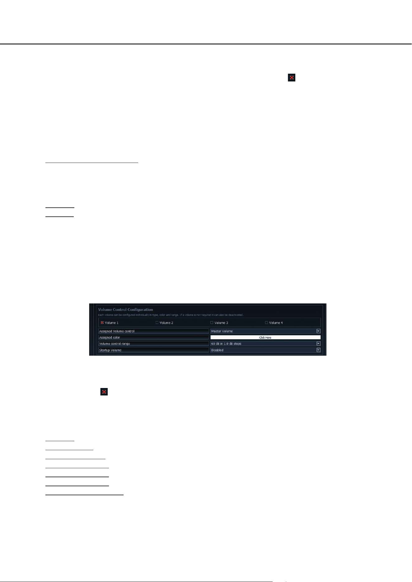
4.2VolumeControlConguration(KongurationderLautstärkeregelungen)
In diesem Bereich können bis zu vier auswählbare Lautstärken individuell konguriert werden. Wird eine Lautstärke
nicht benötigt, kann diese auch deaktiviert werden.
Hinweis: Werden alle vier Lautstärken ausgeschaltet (Disabled) ist das gesamte „Volume Control“-Menü deaktiviert.
4.2.1Lautstärkenauswahl
Hier kann die Lautstärke ausgewählt werden, welche konguriert werden soll. Das rote Kreuz zeigt an, welche der
vier Lautstärken konguriert wird.
4.2.2AssignedVolumecontrol(Lautstärkezuweisung)
An dieser Stelle kann der zuvor ausgewählten Volume eine Lautstärkeregelung zugewiesen werden. Je nach
DSP- Produkt kann die Auswahl variieren.
Disabled: Schaltet die ausgewählte Volume aus
Master Volume: Lautstärkeregelung der globalen Gesamtlautstärke
Subwoofer Volume: Lautstärkeregelung des Subwoofers
Digital Input Volume: Lautstärkeregelung des Digitaleingangs (optisch & elektrisch)
HEC / AUX 1 Volume: Lautstärkeregelung einer optional verbauten Extension Card oder einer AUX Quelle
HEC / AUX 2 Volume:
Lautstärkeregelung einer optional verbauten Extension Card oder einer AUX Quelle (Nur
BRAX DSP)
4.KongurationinderDSPPC-ToolSoftware
15
Rear Attenuation Volume: Bei DSP-Produkten mit VCP kann bei aktiviertem Virtual Channel Processing die
Lautstärke der virtuellen Kanäle „Rear L Full“ und “Rear R Full“ separat geregelt werden.
4.2.3Assignedcolor(Farbzuweisung)
Hier kann jeder Volume eine individuelle Farbe zugewiesen werden, um die unterschiedlichen Volumes schnell
und einfach unterscheiden zu können.
Alle weiteren Menüs haben fest denierte Farbkonzepte.
4.2.4Volumecontrolrange(Lautstärkeregelbereich)
Für jede der vier Volumes kann die Abstufung der Lautstärkeeinstellung der Anwendung entsprechend eingestellt
werden.
60 dB in 1.0 dB steps: Diese Einstellung ist für die meisten Anwendungen die optimale Einstellung. Durch den
großen Regelumfang mit guter Abstufung eignet sie sich vor allem für die Master und Source Volumes (HEC /
AUX / Digital Input).
60 dB in 0.5 dB steps: Durch die sehr kleinen Einstellschritte kann eine sehr genaue Lautstärkeeinstellung vorge-
nommen werden.
24 dB in 0.5 dB steps: Diese Einstellung bietet einen kleineren Regelumfang und eignet sich daher besonders
für die Rear Attenuation Volume, da diese Lautstärke häug nur in geringem Maße an die Wiedergabe angepasst
wird.
12 dB in 0.5 dB steps: Diese Einstellung bietet einen kleinen Regelumfang und eignet sich daher besonders für
die Subwoofer Volume, da diese Lautstärke häug nur in geringem Maße an die Wiedergabe angepasst wird.
4.2.5StartupVolume(Einschalt-Lautstärke)
An dieser Stelle kann eine Lautstärkelimitierung zur Einschaltlautstärke vorgenommen werden. Wenn diese Opti-
on auf „Disabled“ steht, wird nach dem Einschalten des Systems immer die zuletzt eingestellte Lautstärke wieder
hergestellt. Um zu vermeiden, dass das System mit hoher Lautstärke eingeschaltet wird, kann an dieser Stelle die
maximale Einschaltlautstärke limitiert werden. Diese Limitierung gilt nur für den Einschaltvorgang und hat keinen
Einuss auf die maximal einstellbare Lautstärke im Betrieb.
Beispiel: Wird das Soundsystem bei komplett hochgeregelter Master Volume ausgeschaltet, wird dies ohne Ein-
schalten der Startup Volume auch mit voller Lautstärke wieder eingeschaltet. Bei Nutzung der Startup Volume
wird die Lautstärke beim Wiedereinschalten des Systems auf den jeweils eingestellten Wert abgesenkt, sofern
dieser zuvor höher eingestellt war. Wird das System mit geringem Pegel ausgeschaltet, so wird in jedem Fall die
geringe Lautstärke wieder hergestellt, unabhängig welche Option hier gewählt wird.
Disabled: Die Lautstärke wird beim Wiedereinschalten immer auf den zuletzt genutzten Wert gesetzt.
Limited to -15 dB: Die Lautstärke wird beim Wiedereinschalten auf maximal -15 dB (max. 3/4 des gesamten
Regelbereichs) gesetzt, sofern die Lautstärke den Wert beim Ausschalten überschritten hat.
Limited to -30 dB: Die Lautstärke wird beim Wiedereinschalten auf maximal -30 dB (max. die Hälfte des gesamten
Regelbereichs) gesetzt, sofern die Lautstärke den Wert beim Ausschalten überschritten hat.
Limited to -45 dB: Die Lautstärke wird beim Wiedereinschalten auf maximal -45 dB (max. 1/4 des gesamten
Regelbereichs) gesetzt, sofern die Lautstärke den Wert beim Ausschalten überschritten hat.
Anwendungsbeispiel bei 100 % Lautstärkepegel:
Disabled –
Lautstärke nach
Wiedereinschalten
(100 %)
Lautstärkepegel vor
Ausschalten (100 %)
Limited to -30 dB –
Lautstärke nach
Wiedereinschalten
(50 %)
de
16
4.KongurationinderDSPPC-ToolSoftware
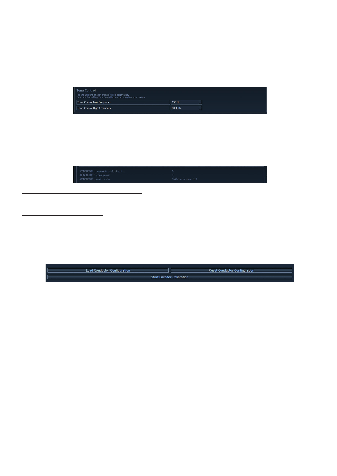
4.3ToneControl
In diesem Menü können die Frequenzen festgelegt werden, in deren Bereich eine Anhebung oder Absenkung der Laut-
stärke wirkt. Der Gain-Regelbereich ist fest auf −6 dB bis +6 dB begrenzt und kann nicht verändert werden.
Um Einstellungen vornehmen zu können, muss das Menü zuvor in der Menü-Aktivierung aktiviert werden (siehe Sei-
te 14, Punkt 4.1.3).
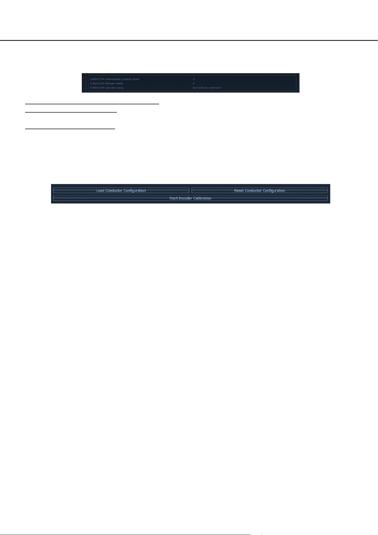
4.4CONDUCTORStatus
Hier können alle wichtigen Status-Informationen des CONDUCTORs abgelesen werden.
CONDUCTOR communication protocol version: Zeigt die aktuelle Version des Kommunikationsprotokolls an.
CONDUCTOR rmware version: Zeigt die aktuelle Firmware-Version des CONDUCTORs an. Die Firmware wird auto-
matisch beim Önen der DSP PC-Tool Software auf den aktuellsten Stand gebracht.
CONDUCTOR operation status: Zeigt den Betriebszustand des CONDUCTORs an.
4.5CONDUCTOREinstellungenladen&zurücksetzen
An dieser Stelle lassen sich Kongurationseinstellungen eines CONDUCTORs aus älteren DSP PC-Tool Versionen
(4.75a bis 5) über eine CONDUCTOR-Kongurationsdatei („.afcc“-Datei) in das DSP PC-Tool 6 importieren.
Zudem kann die gesamte Konguration auf die Standardwerte zurückgesetzt werden.
17
5.Standard-Konguration
Im Auslieferungszustand sind folgende Optionen konguriert:
• Main menu: Volume Control → Der CONDUCTOR startet immer mit ausgewählter Master Volume.
• Automatic switch back to Main menu: Enabled → Der CONDCUTOR schaltet nach 5 Sekunden Inaktivität automa-
tisch wieder auf das Master Volume Menü zurück.
• Standardmäßig ist nur das „Sound Setup selection“ Menü aktiviert, in welchem zwischen den verschiedenen
DSP-Speicherplätzen umgeschaltet werden kann. Das „Signal Input selection“ Menü sowie das „Bluetooth Playback
Control“ Menü sind standardmäßig deaktiviert. Somit sind im Auslieferungszustand zwei „Volume Control“ Menüs
(Master und Subwoofer Volume) sowie das „Sound Setup selection“ Menü aktiv.
• LED Brightness: 70 % → Die Standard-Helligkeit beträgt 70 % der Maximalhelligkeit.
• LED Dimming: 50 % of LED Brightness → Nach 8 Sekunden Inaktivität wird die Helligkeit um 50 % reduziert.
• Installation Orientation: 0° Rotation → Standardmäßig ist die Rotation aus, so dass die Rastkerbe des CONDCUTORs
auf der 12 Uhr Position steht.
• Volume 1 → Diese Volume ist standardmäßig als „Master Volume“ (Gesamtlautstärke) konguriert. Die Volume hat
die Farbe weiß und einen Regelbereich von 60 dB, welcher sich in 1 dB Schritten regeln lässt. Das Startup Volume
ist standardmäßig deaktiviert (disabled), so dass bei jedem Systemstart die zuvor eingestellte Lautstärke wieder
hergestellt wird.
• Volume 2 → Diese Volume ist standardmäßig als „Subwoofer Volume“ (Subwooferlautstärke) konguriert. Die Volu-
me hat die Farbe rot und einen Regelbereich von 24 dB, welcher sich in 0,5 dB Schritten regeln lässt. Das Startup
Volume ist standardmäßig deaktiviert (disabled), da diese Funktion bei der Subwoofer-Volume nicht benötigt wird.
de
18
Problem:CONDUCTORzeigtFehlercodean
Sollte es zu einem Problem bei Verbindungsaufbau kommen, zeigt der CONDUCTOR verschiedene Fehlercodes an.
Fehlercode1:
Ursache: Das angeschlossene Gerät wird nicht unterstützt. Der CONDUCTOR ist nur
kompatibel mit Geräten, welche mit der ACO-Plattform ausgestattet sind.
Ebenso kann eine Unterbrechung in der Zuleitung vorliegen, wodurch keine Ver-
bindung zwischen dem DSP und CONDUCTOR zustande kommt.
Problemlösung: Bitte überprüfen Sie die Zuleitung und die Steckverbindung, um sicherzustellen,
dass alles korrekt verbunden ist.
Fehlercode2:
Ursache: Die CONDUCTOR Software ist nicht auf dem aktuellsten Stand und benötigt ein
Update.
Problemlösung: Verbinden Sie Ihren DSP / DSP-Verstärker mit einem PC und starten die ak-
tuellste DSP PC-Tool Software. Das CONDUCTOR Update wird anschließend
automatisch durchgeführt.
Fehlercode3:
Ursache: Die ACO-Plattform des DSP / DSP-Verstärkers ist nicht auf dem aktuellsten
Stand und benötigt ein Update.
Problemlösung: Verbinden Sie Ihren DSP / DSP-Verstärker mit einem PC und starten die aktu-
ellste Version der DSP PC-Tool Software. Das ACO Update wird anschließend
automatisch gestartet.
Fehlercode4:
Ursache: Der CONDUCTOR ist im DSP / DSP-Verstärker nicht aktiviert.
Problemlösung: Aktivieren Sie den CONDUCTOR wie auf Seite 7 im Kapitel 2.3 „Anschluss des
CONDUCTORs an einen DSP / DSP Verstärker“ beschrieben.
Fehlercode5:
Ursache: Es sind vermehrt Übertragungsfehler zwischen dem CONDUCTOR und der
ACO-Plattform des DSP / DSP-Verstärkers aufgetreten.
Problemlösung: Überprüfen Sie das Kabel auf Beschädigungen und die Steckverbinder auf
einen festen Sitz.
6. Problembehandlung
19
Fehlercode6:
Ursache: DSP im Signalprozessor / DSP-Verstärker ist nicht gestartet.
Problemlösung: Verbinden Sie Ihren DSP / DSP-Verstärker mit einem PC und starten die
aktuellste DSP PC-Tool Software. DSP Software mit aktuellem DSP PC-Tool
updaten.
Fehlercode7:
Ursache: Das angeschlossene Gerät bendet sich im Protection Mode.
Problemlösung: Beheben Sie die Ursache für den Protection Mode. Informationen dazu nden
Sie in der jeweiligen Bedienungsanleitung des DSPs / DSP-Verstärkers unter
dem Punkt „Stauts LED“.
Fehlercode8:
Ursache: Ein unbekannter Fehler ist aufgetreten.
Problemlösung: Überprüfen Sie alle Steckverbindungen und nutzen Sie die aktuellste DSP PC-
Tool Version.
Problem:CONDUCTORschaltetnichtein
Mögliche Ursache: Steckverbindung fehlerhaft.
Problemlösung: Steckverbinder auf festen Sitz prüfen.
Problem:LED-Beleuchtunggehtaus
Mögliche Ursache: Die „LED Dimming“ Einstellung ist auf „LEDs o“ konguriert, wodurch die Beleuchtung nach
8 Sekunden Inaktivität abgeschaltet wird. Sollte dies nicht der Fall sein, überprüfen Sie die Verka-
belung.
Problemlösung: Überprüfen Sie die Einstellung „LED Dimming“ wie auf Seite 14 im Punkt 4.1.5 beschrieben.
Problem:KeinTon
Mögliche Ursache: Lautstärke zu gering eingestellt; Mute aktiviert; falsche Eingangsquelle.
Problemlösung: Lautstärkepegel der Volumes 1 - 4 überprüfen und ob diese im DSP PC-Tool aktiviert sind; Mute
deaktivieren (Der Mute wird durch eine rotierende, einzelne LED signalisiert / De-Mute: Der Dreh-
regler muss bei angewähltem Volume Menü lange gedrückt oder gedreht werden); Eingangsquelle
umschalten.
Problem:KeineVerbindungmitkompatiblemGerätmöglich
Mögliche Ursache: Übertragungsproblem zum DSP; inkompatible Softwareversionen.
Problemlösung: CONDUCTOR Steckverbinder auf festen Sitz prüfen; CONDUCTOR und ACO-Software mit aktu-
ellem DSP PC-Tool updaten.
de

20
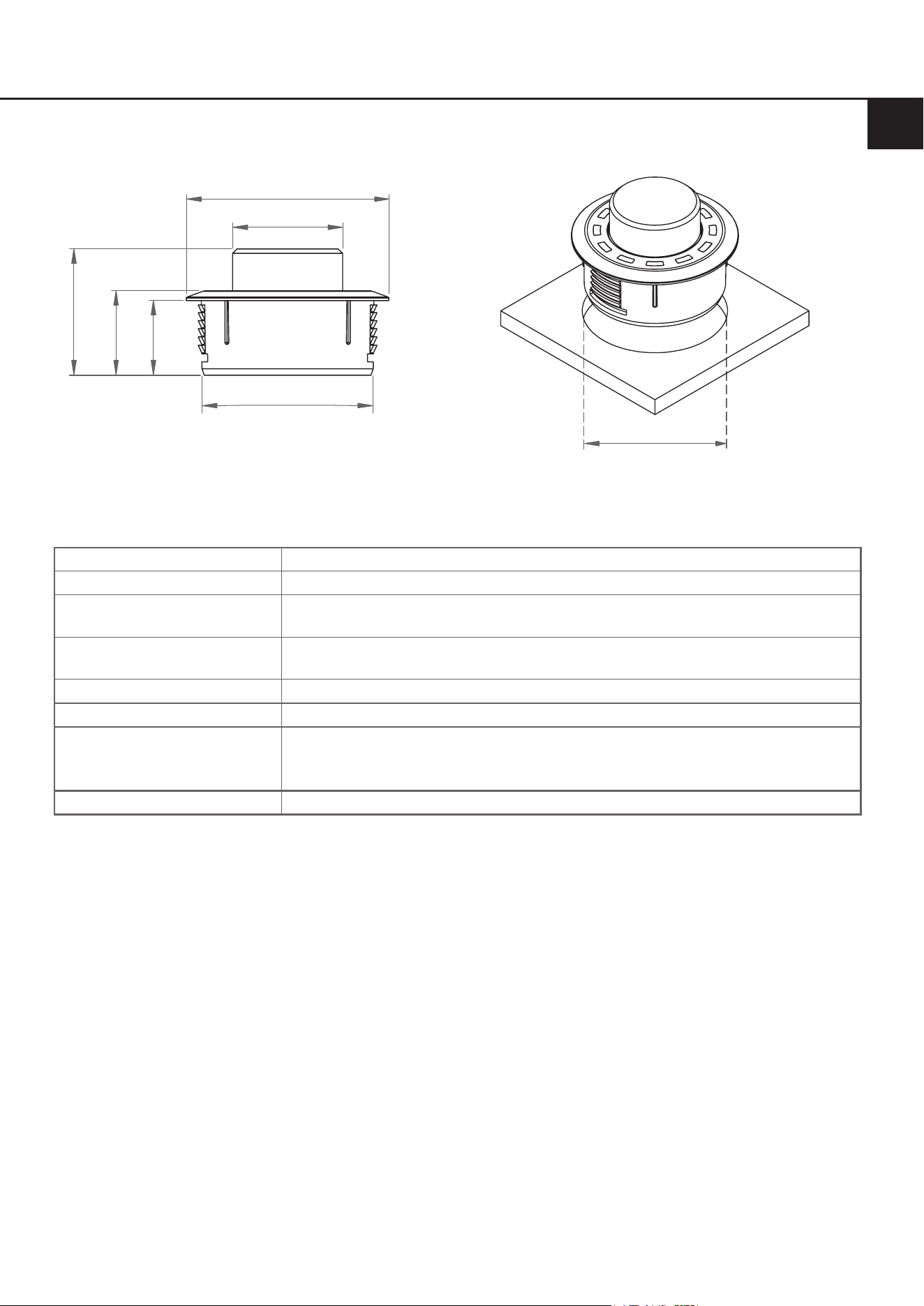
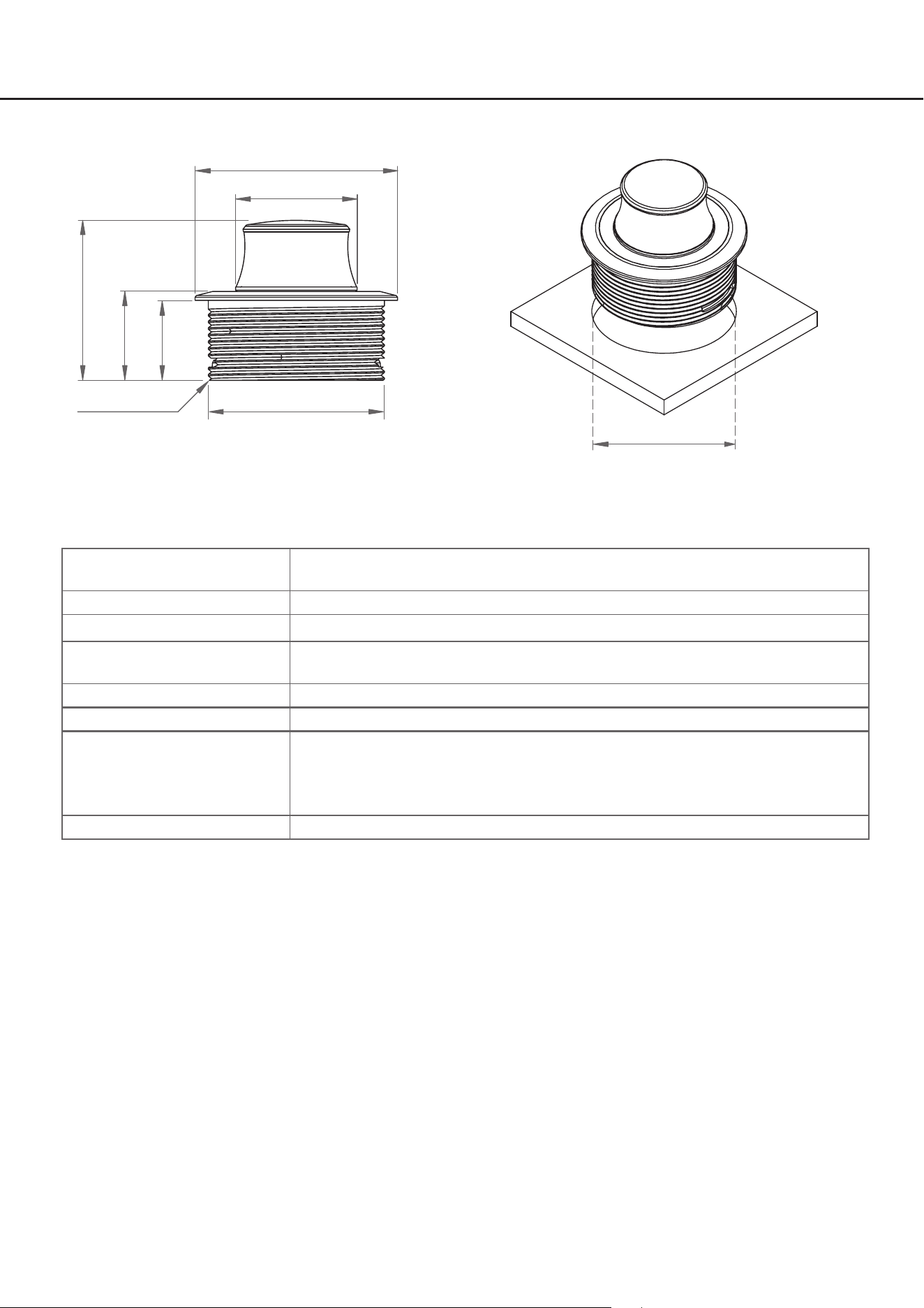
7. Technische Daten
* Alle Abmessungen in mm
Lochausschnitt
CONDUCTOR PRO
Ø 27,6
Ø 46
Ø 40
36
20
18
M40 x 1,5
Ø 40
Gehäuse Aluminium-Gehäuse mit ergonomischem Drehknopf mit Rubber-Touch-Beschich-
tung an der Seite
Hardware Dreh-Encoder, 12 x RGB-LEDs & 48 MHz ARM Prozessor
Anschluss SCP (Smart Control Port) / keine separate Stromversorgung notwendig
Kabellänge 5 m – trennbar, 4,8 m Verbindungskabel
+ 0,2 m CONDUCTOR PRO-Kabel
Abmessungen(Ø xH) Ø 46 x 36 mm
Einbautiefe 18 mm
Kompatibilität Der CONDUCTOR PRO ist ausschließlich für BRAX, HELIX und MATCH DSPs /
DSP-Verstärker mit ACO (Advanced CoProcessor) und SCP (Smart Control Port)
geeignet.
Eine aktuelle Kompatibilitäsübersicht nden Sie auf
www.audiotec-scher.de/ conductor-pro
DSPPC-ToolKompatibilität Version 5 und höher
21
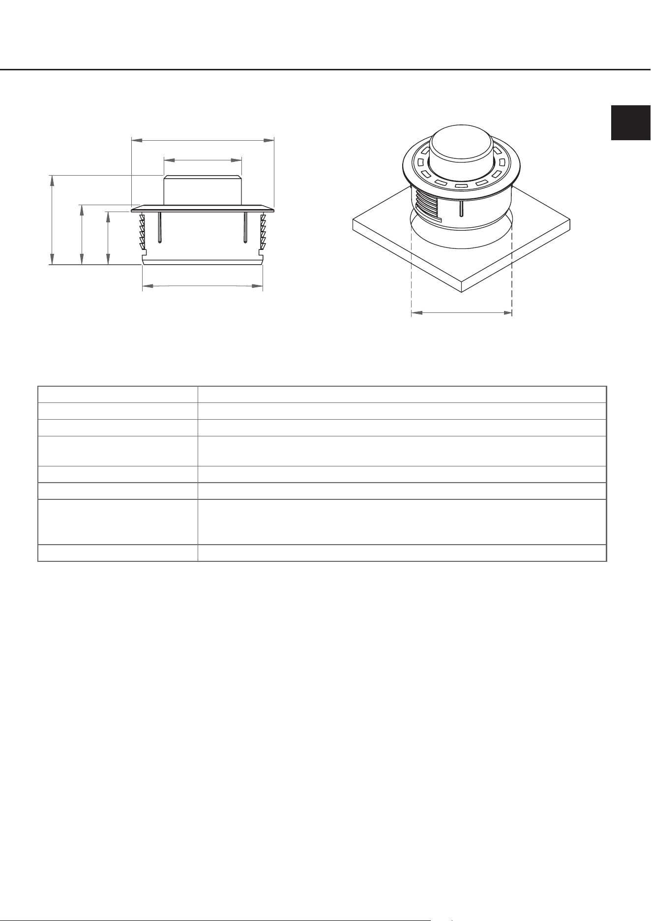
* Alle Abmessungen in mm
Lochausschnitt
CONDUCTOR
Ø 40
Ø 39,2
Ø 46
Ø 25
17
19,2
28,7
de
Gehäuse ABS Gehäuse mit gebürstetem Aluminium-Knopf
Hardware Dreh-Encoder, 12 x RGB-LEDs & 48 MHz ARM Prozessor
Anschluss SCP (Smart Control Port) oder Control Input / keine separate Stromversorgung
notwendig
Kabellänge 5 m – trennbar, 4,8 m Verbindungskabel
+ 0,2 m CONDUCTOR-Kabel
Abmessungen(Ø xH) Ø 46 x 28,7 mm
Einbautiefe 17 mm
Kompatibilität Der CONDUCTOR ist ausschließlich für BRAX, HELIX und MATCH DSPs /
DSP-Verstärker mit ACO (Advanced CoProcessor) geeignet. Eine aktuelle Kom-
patibilitäsübersicht nden Sie auf www.audiotec-scher.de/conductor
DSPPC-ToolKompatibilität Version 4.75a und höher
22
8.RechtlicheHinweise
Garantiehinweise
Die Garantieleistung entspricht der gesetzlichen Regelung. Von der Garantieleistung ausgeschlossen sind Defekte
und Schäden, die durch Überlastung oder unsachgemäße Behandlung entstanden sind. Eine Rücksendung kann
nur nach vorheriger Absprache in der Originalverpackung, einer detaillierten Fehlerbeschreibung und einem gültigen
Kaufbeleg erfolgen. Technische Änderungen, Druckfehler und Irrtümer vorbehalten! Für Schäden am Fahrzeug oder
Gerätedefekte, hervorgerufen durch Bedienungsfehler des Gerätes, können wir keine Haftung übernehmen.
Markenzeichen
Die Bluetooth
®
Wortmarke und die Logos sind eingetragene Warenzeichen der Bluetooth SIG,
Inc. und jegliche Nutzung dieser Marken durch die Audiotec Fischer GmbH geschieht unter
Lizenz. Andere Handelsmarken und Handelsnamen gehören den jeweiligen Inhabern.
HinweisezurEntsorgung
Dieses Symbol bedeutet, dass das Produkt nicht über den Hausmüll entsorgt werden darf, sondern bei
einer entsprechenden Sammelstelle zum Recycling abgegeben werden muss. Befolgen Sie die ört-
lichen Vorschriften und entsorgen Sie das Produkt niemals mit dem normalen Hausmüll. Die ordnungs-
gemäße Entsorgung von Altgeräten trägt zur Vermeidung von Umwelt- und Gesundheitsschäden bei.
RegulatorischeHinweise
Dieses Produkt ist mit einer CE-Kennzeichnung versehen. Damit ist das Gerät für den Betrieb in Fahr-
zeugen innerhalb der Europäischen Union (EU) zertiziert.
Dieses Produkt ist mit einer UKCA-Kennzeichnung versehen. Damit ist das Gerät für den Betrieb in Fahr-
zeugen innerhalb des Vereinigten Königreichs zertiziert.
Dieses Produkt ist mit einer EAC-Kennzeichnung versehen. Damit ist das Gerät für den Betrieb in Fahr-
zeugen innerhalb der Eurasian Customs Union zertiziert.

23
Table of contents
1.Generalinformation ................................................................................................................... 25
2.Installationinstructions............................................................................................................. 26
2.1 Assembling the CONDUCTOR PRO ...............................................................................................................26
2.2 Assembling the CONDUCTOR ........................................................................................................................27
2.3 ConnectingtheCONDUCTOR/PROtoaDSP/DSPamplier .................................................................... 28
3.OperatingtheCONDUCTOR/PRO ............................................................................................. 29
3.1 VolumeControlconguration(Volumemenu1-4) ...................................................................................... 31
3.2 ToneControl menu ............................................................................................................................................ 32
3.3 Signal Input selection menu ............................................................................................................................ 32
3.4 SoundSetupselectionmenu .......................................................................................................................... 33
3.5 Bluetooth Playback Control menu .................................................................................................................. 34
4.CongurationintheDSPPC-Toolsoftware ............................................................................... 35
4.1 Generalconguration ...................................................................................................................................... 35
4.1.1 Mainmenu...............................................................................................................................................35
4.1.2 Automaticswitchbacktomainmenu .................................................................................................. 35
4.1.3 Menuactivation ...................................................................................................................................... 35
4.1.4LEDbrightness ....................................................................................................................................... 36
4.1.5 LEDDimming .......................................................................................................................................... 36
4.1.6 Installationorientation ........................................................................................................................... 36
4.2 VolumeControlConguration ........................................................................................................................ 36
4.2.1 Volumeselection .................................................................................................................................... 36
4.2.2 AssignedVolumecontrol ...................................................................................................................... 36
4.2.3 Assignedcolor ....................................................................................................................................... 36
4.2.4 Volumecontrolrange ............................................................................................................................. 37
4.2.5 StartupVolume ....................................................................................................................................... 37
4.3 ToneControl ...................................................................................................................................................... 37
4.4 CONDUCTORstatus ........................................................................................................................................37
4.5 LoadingandresettingCONDUCTORsettings ...............................................................................................38
5.Defaultconfiguration ................................................................................................................. 39
6.Troubleshooting ......................................................................................................................... 40
7. Technical data ............................................................................................................................ 42
8.Legalinformation ....................................................................................................................... 44
en

24
Congratulations
Dear Customer,
Congratulations on purchasing this high-quality control unit with RGB-LED feedback.
We developed the CONDUCTOR based on state-of-the-art engineering and this is reected in its exceptional quality
and the impressive use of sophisticated technologies.
We hope you enjoy using this product.
The
AUDIOTEC FISCHER Team
25
1.Generalinformation
To make optimal use of all the possibilities aorded by the product, please carefully read through the following installa-
tion instructions. We guarantee that the awless condition of every device has been checked before delivery.
We recommend appointing a specialist to install the product, as the verication of professional installation and connec-
tion of the device is a prerequisite for the warranty services.
Install your CONDUCTOR in a dry place in the car. Do not t the device near parts that radiate heat or near the vehicle’s
electronic control units.
Toprotectagainstaccidents,theCONDUCTORmustbeprofessionallymountedsothatthecontrolunitdoes
notpose a danger to passengers and/or the vehicleduringa critical driving situation, such as emergency
braking.
Information on professional installation is provided in the “Installation instructions” chapter on the following pages.
Important: During assembly, make sure that none of your vehicle’s safety systems (e.g. airbag) are negatively aected
in their function.
• Do not mount the CONDUCTOR on an airbag cover (e.g. steering wheel, A pillar or dashboard on the passenger
side)
• Do not fasten the control unit in the driver’s eld of vision
• Do not place the CONDUCTOR loose on the dashboard
Before cutting the slot to mount the device, make sure that no electrical cables and components, etc., are concealed
in the area behind it. Otherwise, these could be damaged. Please be aware that these kinds of parts may also be con-
cealed in double-skin panelling.
The cable connections must be routed so that no risk of clamping, crushing or breakage exists. In case of sharp edges
(sheet metal cutouts), all cables must be cushioned against chang. In addition, the connecting cable must never be
routed together with lines / cables for vehicle appliances (fan motors, re detection modules, fuel lines, etc.).
en
26
2. Installation instructions
2.1 Assembling the CONDUCTOR PRO
46
Lochausschnitt
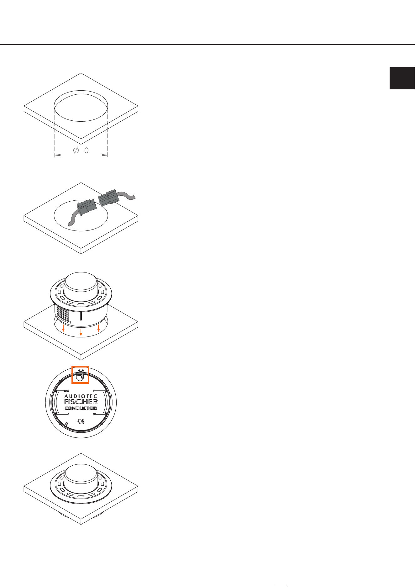
i. Cutting out the mounting slot
To ensure a safe and professional assembly, the cutout must not be more than
40 mm in size. Please make sure that the space between the CONDUCTOR
PRO and other parts, such as switches, control elements, etc., is adequate
with a sucient installation depth. This is particularly important if installation
slots need to be cut out. All the data on the installation depth and the diameter
of the CONDUCTOR PRO is provided in the technical data in these instruc-
tions. Please make sure that the contact surface is as level and stable as
possible.
Inserting the CONDUCTOR PRO
Insert the housing evenly into the panel cutout.
IMPORTANT: To avoid damage, never apply pressure to the rotary knob in
the center of the CONDUCTOR PRO during installation. Press only on the
surrounding housing.
For correct alignment of the CONDUCTOR PRO, use the cable entry on the
rear of the housing as a reference (see third gure on the left).
In the installed position, the cable entry must be aligned to the 12 o’clock
position. If the installation situation prevents the CONDUCTOR PRO from
being installed in the 12 o’clock position, it can also be rotated in 30° steps for
installation. The LED display can then be adjusted to the installation position
in the DSP PC-Tool software (see page 36, “Installation orientation”).
Securing the CONDUCTOR PRO
Once the CONDUCTOR PRO is in its nal mounting position and the alumi-
num housing sits ush, route the 20 cm CONDUCTOR PRO cable through
the mounting ring and then screw the ring onto the housing. Tighten the ring
by hand.
Do not overtighten the ring, as this may cause damage to the CONDUCTOR
PRO or the vehicle interior.
Routing and connecting the CONDUCTOR PRO connection cable
Route the 4.8 m connecting cable and connect it to the 20 cm CONDUCTOR
PRO cable.
iii.
v.
ii.
CONDUCTOR
cable
Connection
cable
iv.
27
en
46
Slot
i. Cutting out the mounting slot
To ensure a safe and professional assembly, the cutout must not be more
than 40 mm in size. Please make sure that the space between the CONDUC-
TOR and other parts, such as switches, control elements, etc., is adequate
with a sucient installation depth. This is particularly important if installation
slots need to be cut out. All the data on the installation depth and the diameter
of the CONDUCTOR is provided in the technical data in these instructions.
Please make sure that the contact surface is as level and stable as possible.
Routing and connecting the CONDUCTOR connection cable
Route the 4.8 m connecting cable and guide it through the installation open-
ing from the rear. Then connect the cable to the 20 cm CONDUCTOR cable.
Inserting the CONDUCTOR
Press the housing evenly into the panel cutout.
IMPORTANT: To avoid damage, never push on the aluminum button in the
center of the CONDUCTOR during assembly, only on the surrounding plastic
housing.
Use the 12 o’clock marking on the housing (see fourth gure on the left) as a
guide to align the CONDUCTOR.
If the installation situation prevents the CONDUCTOR from being installed in
the 12 o’clock position, it can also be rotated in 30° steps for installation. The
LED display can then be adjusted to the installation position in the DSP PC-
Tool software (see page 36, “Installation orientation”).
The plastic housing should lie ush once you have moved the CONDUCTOR
to its nal installation position.
2.1 Assembling the CONDUCTOR
iii.
v.
ii.
CONDUCTOR
cable
Connection
cable
iv.
28
2. Installation instructions
2.3ConnectingtheCONDUCTOR/PROtoaDSP/DSPamplier
1. Connect the CONDUCTOR connection cable to the DSP / DSP amplier
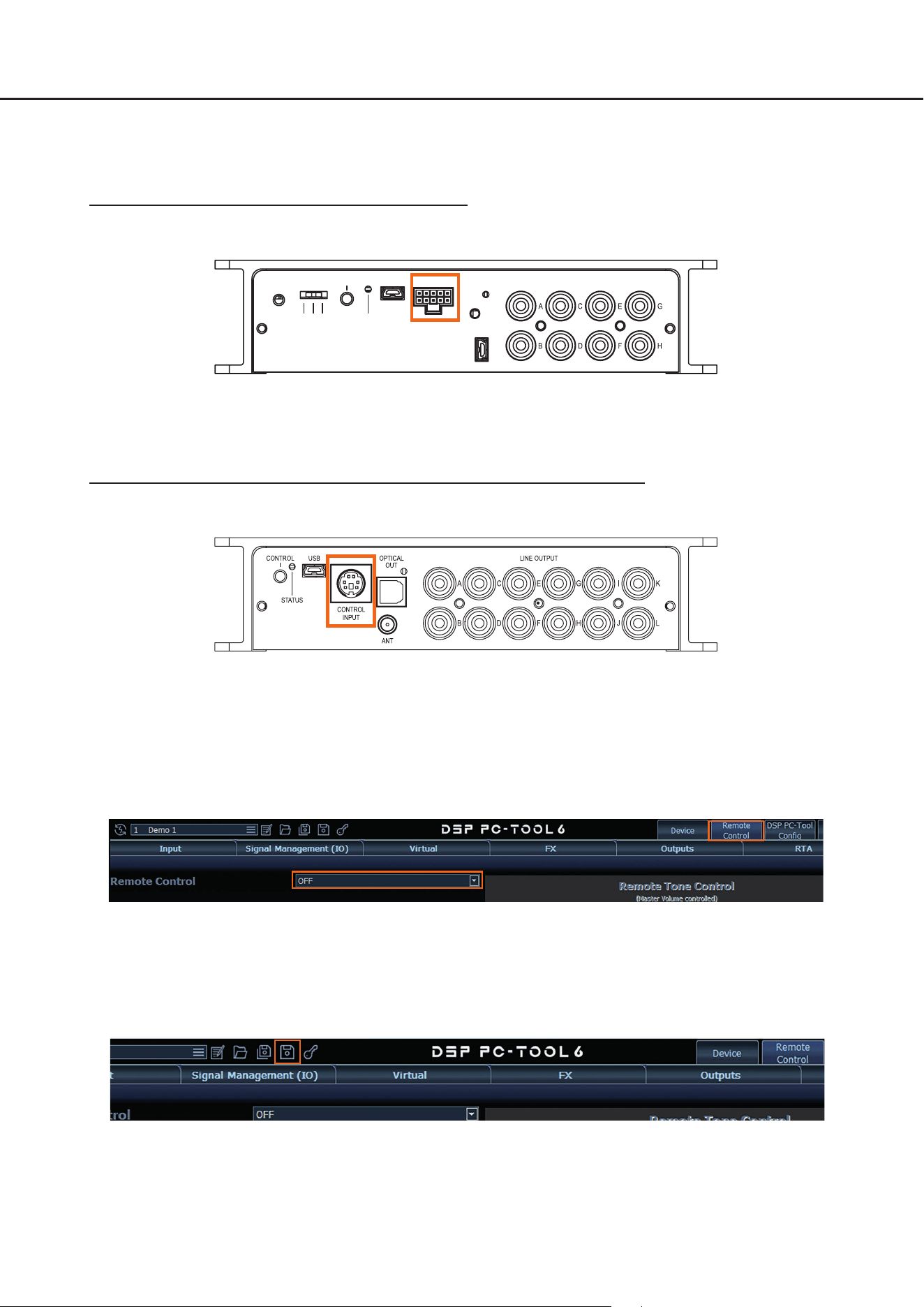
1.1 DSP / DSP amplier with SCP (Smart Control Port)
Insert the SCP connector of the CONDUCTOR connection cable into the multifunction port (SCP) of the DSP /
DSP amplier.
USB-AUDIO
GND
ISO 200Ω
CONTROL
STATUS
USB LINE OUTPUT
SCP
Note: If your CONDUCTOR is not equipped with a SCP connector (“for Control Input” version), an SCP-to-Control
Input adaptor (art. no. M141313) is optionally available from your authorized dealer.
1.2 DSP / DSP amplier with Control Input (only CONDUCTOR for Control Input)
If your DSP device is still equipped with a Control Input, insert the round connector of the CONDUCTOR con-
nection cable into the multifunction port (Control Input) of the DSP / DSP amplier.
Turn your sound system on and then start the DSP PC-Tool software. You can nd the software at
www.audiotec-scher.de/dsp-pc-tool (compatible from DSP PC-Tool software version 5).
Power is supplied to the CONDUCTOR / PRO via the DSP and it is switched on automatically.
2. Open the „Remote Control“ menu (1) in the DSP PC-Tool. There (2), select the CONDUCTOR / PRO to open its
conguration menu.
2
1
3. You can now change other CONDUCTOR / PRO settings. More information on the conguration is provided on
page 35 et seq., “Conguration in the DSP PC-Tool software”.
4. To complete the process, save the settings and the activation of the CONDUCTOR / PRO in the DSP / DSP ampli-
er by clicking on the “Save” button in the DSP PC-Tool.

29
3. Operating the CONDUCTOR / PRO
The CONDUCTOR is operated by turning and pressing the knob. The LED lighting provides feedback on the selected
menu and the action performed.
Knob
RGB LED
You can switch between the various menus by briey pressing the button. The volume and the available menu options
are selected by turning the knob. Pressing and holding the button conrms the selection or mutes the selected volume.
In addition, if a Bluetooth module (BT Extension Card) is installed, the “Next track” function can be enabled by dou-
ble-press and the “Previous track” function is enabled by triple-press in every volume menu. Further information on the
functions and the LED feedback in a menu is provided on the following pages.
Note: If a menu or a volume is not enabled in the DSP PC-Tool, the next active menu or active volume is selected.
en
30
3. Operating the CONDUCTOR / PRO
*Only for devices with an optionally installed Extension Card BT
Volume 1
Turn: Adjust volume
Long press: Mute / demute
Double-press: Next track*
Triple-press: Previous track*
Extra-long press (5 sec.): Start Bluetooth pairing*
Volume 2
Turn: Adjust volume
Long press: Mute / demute
Double-press: Next track*
Triple-press: Previous track*
Extra-long press (5 sec.): Start Bluetooth pairing*
Volume 3
Turn: Adjust volume
Long press: Mute / demute
Double-press: Next track*
Triple-press: Previous track*
Extra-long press (5 sec.): Start Bluetooth pairing*
Volume 4
Turn: Adjust volume
Long press: Mute / demute
Double-press: Next track*
Triple-press: Previous track*
Extra-long press (5 sec.): Start Bluetooth pairing*
Sound Setup selection
Turn: Select Sound Setup
Long press: Activate Sound Setup
Colors: Green (active), yellow (inactive), red (not available)
ToneControl
Turn: Adjust ToneControl gain
Long press: Switch ToneControl frequency range
Colors: Lila (Low Frequency), yellow (high frequency)
Bluetooth Playback Control*
Long press: Play / pause
Left turn: Previous track
Right turn: Next track
Extra-long press (5 sec.): Start Bluetooth pairing
Short press 1x
Short press 1x
Short press 1x
Short press 1x
Short press 1x
Short press 1x
Activating digital coaxial input
Digital optical input (yellow) is activated
Long press: Switching between optical
and coaxial input (orange)
Note: Menu navigation is cyclic. The menu sequence begins in the present menu.
Short press 1 x
Signal Input selection
Turn: Select signal input
Long press: Activate signal input
Colors: Green (main), yellow (digital input), blue (HEC1),
turquoise (HEC2)
Short press 1 x
31
3.1VolumeControlConguration(Volumemenu1-4)
The four volume menus let you separately control up to 4 dierent volumes (master, digital, HEC/AUX, subwoofer vol-
ume, Rear Attenuation, etc.). These can be set as described under point 4.2 “Volume Control Conguration” on page 36.
The volume menus are restored to the most recently set values after restarting the system. If the “Startup volume” op-
tion (see page 37, point 4.2.5) has been congured, the volume is switched back on at the maximum set limit level, if
this was exceeded when the device was switched o.
If a volume is turned down completely, the volume is muted independent of the set range.
Actions:
Turn: Set volume level
Long press: Mute / demute
Double-press: Next track*
Triple-press: Previous track*
Extra-long press (5 sec.): Start Bluetooth pairing*
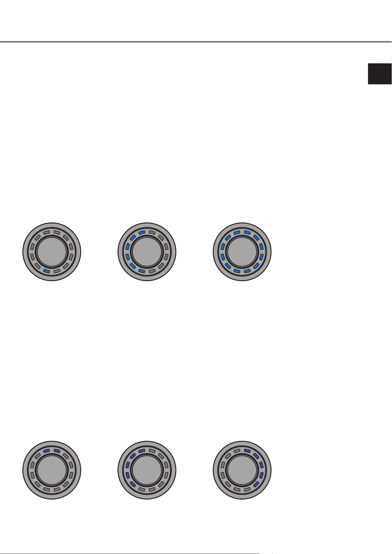
LEDfeedback:
The set volume level is displayed by the bottom-left LEDs in a clockwise direction in the color assigned for the volume.
Muting (long press) is signaled by a single rotating LED.
Changing the volume when muted cancels the muting.
Minimum volume Maximum volume50 % volume
3.2 ToneControl menu
The ToneControl menu allows you to adjust the sound using a high and low shelf lter. The volume can be changed in
the range from -6 dB to +6 dB, allowing you to boost or cut the highs and lows as desired.
The frequencies for the high and low shelf lters can be dened individually in the DSP PC-Tool software (see page 37,
point 4.3).
Actions:
Turn: Adjust ToneControl gain
Long press: Switch ToneControl frequency range (High Frequency / Low Frequency)
LEDfeedback:
Lila: Low Frequency
Ywellow: High Frequency
0 dB +6 dB-6 dB
* Only for devices with anoptionally installed Extension Card BT
en
32
3. Operating the CONDUCTOR / PRO
3.3 Signal Input selection menu
The “Signal Input selection” menu lets you switch between the signal sources connected to the DSP / DSP amplier.
The menu starts with the currently selected or most recently active input.
Actions:
Turn: Select signal input
Long press: Activate signal input
LEDfeedback:
Green: Main input
Yellow: Digital optical input
Orange: Digital coaxial input (Input can only be selected when the optical digital input is activated / see below)
Blue: Extension Card 1 (HEC1)
Turquoise: Extension Card 2 (HEC2 – only BRAX DSP)
Main input
Digital optical
input
HEC1 HEC2
Digital coaxial
input
With digital input activated,
press long to switch
between optical and coaxial
input
Note: The CONDUCTOR automatically detects the signal inputs of the connected DSP / DSP amplier. Only the avail-
able signal inputs can be selected. All other inputs are not displayed by LED feedback and cannot be selected.
33
3.4SoundSetupselectionmenu
The “Sound Setup selection” menu lets you switch between the DSP’s up to 10 Sound Setups. The menu starts with the
currently selected or most recently active Sound Setup.
Actions:
Turn: Select Sound Setup
Long press: Activate Sound Setup
LEDfeedback:
Green: Sound Setup active
Yellow: Sound Setup memory space occupied, setup inactive
Red: Sound Setup memory space empty, cannot be selected
You can use the CONDUCTOR to select and enable the DSP’s 10 Sound Setup memory spaces. The memory spaces
are displayed as follows:
1
2
3
4
5 6
7
8
9
10
Examples of the LED feedback in the “Sound Setup selection” menu:
Sound Setup no. 5
enabled
Sound Setup no. 5 not
occupied and can also
not be selected
Sound Setup no. 5 avail-
able – can be enabled
by holding down the
button
en
34
3. Operating the CONDUCTOR / PRO
3.5BluetoothPlaybackControlmenu*
The “Bluetooth Playback Control” menu lets you control an optionally installed Bluetooth module (play / pause, next /
previous track, enable pairing mode). The menu always starts with the play / pause function (four top LEDs lit).
Actions:
Turn: Perform action automatically
Left turn: Counter-clockwise: Previous track
Right turn: Clockwise: Next track
Long press: Play / pause
Extra-long press (5 sec.): Start Bluetooth pairing
LEDfeedback:
Previous track Play / pause by a long
press of the button
Next track
* Only for devices with an optionally installed Extension Card BT
35
4.CongurationintheDSPPC-Toolsoftware
Overviewofthecongurationmenu
The conguration menu is located in the “Remote Control” menu of the DSP PC-Tool software. However, the menu is
only visible if you have selected the CONDUCTOR / PRO as described on page 28.
All CONDUCTOR settings are changed in the conguration menu.
The menu is divided into the “General Conguration”, “Volume Control Conguration” and “Status” area.
4.1GeneralConguration
The “General Conguration” area is used for all the basic Menu Conguration and LED display (LED Conguration)
settings.
4.1.1Mainmenu
This is where the CONDUCTOR’s start menu, which is accessed immediately after the DSP is switched on, is
dened.
Volume Control, Signal Input selection, Sound Setup selection and Bluetooth Playback Control menu are avail-
able for selection.
4.1.2Automaticswitchbacktomainmenu
If the function is enabled, the CONDUCTOR switches back to the set “Main menu” after around 5 seconds, if
another menu was previously selected. If the function is disabled, the currently selected menu remains selected
until it is manually changed by briey pressing the button.
4.1.3Menuactivation
This lets you enable and disable the volume controls as well as other menus. If a menu is disabled, it cannot be
selected by the CONDUCTOR.
en
36
4.CongurationintheDSPPCToolsoftware
Note: The “Volume Menu” is always enabled and can only be switched o by disabling all four volumes in the
“Volume Control Conguration” (see point 4.2).
An enabled menu can be recognized by a red cross in front of the menu name.
Note: The start menu set in the “Main menu” is automatically enabled.
4.1.4LEDbrightness
This lets you set the brightness of the LED lighting. This is set to 70 % by default.
4.1.5LEDDimming
This menu lets you congure the optional dimming of the LEDs. When this function is enabled, the LEDs are au-
tomatically dimmed by the congured value or switched o completely after 8 seconds of inactivity.
5 % - 75 % of LED brightness: The LEDs are dimmed by the set percentage based on the set LED brightness. A
dimming level of 50 % is set by default. The selection range may be restricted depending on the set brightness of
the LED lighting (LED brightness).
Example: LED brightness 50 %, LED dimming 50 %
The set LED brightness of 50 % is now dimmed by an additional 50 %.
Disabled: Switches the “LED dimming” o.
LEDs o: Switches the LED lighting o completely.
4.1.6Installationorientation
If the installation situation prevents the CONDUCTOR from being installed in the 12 o’clock position, it can also
be rotated in 30° steps for installation. The LED display can then be adapted to the installation position in the DSP
PC-Tool software (see page 26 - 27, “Assembling the CONDUCTOR”).
4.2VolumeControlConguration
This lets you individually congure up to four selectable volumes. Any volume that is not required can also be disabled.
Note: If all four volumes are disabled, the entire “Volume Control” menu is disabled.
4.2.1Volumeselection
This is where the volume to be congured can be selected. The red cross indicates which of the four volumes is
being congured.
4.2.2AssignedVolumecontrol
This is where a volume control can be assigned to the previously selected volume. The selection may vary de-
pending on the DSP product.
Disabled: Switches the selected volume o
Master Volume: Volume control for the global master volume
Subwoofer Volume: Volume control for the subwoofer
Digital Input Volume: Volume for the digital input (optical and electric)
HEC/AUX 1 Volume: Volume for an optionally installed Extension Card or an AUX input
HEC/AUX 2 Volume:
Volume for an optionally installed Extension Card or an AUX input (only BRAX DSP)
Rear Attenuation Volume: For DSP products with VCP, the volume of the virtual channels “Rear L Full” and “Rear
R Full” can be controlled separately when Virtual Channel Processing is enabled.
4.2.3Assignedcolor
This is where an individual color can be assigned to every volume in order to quickly and easily distinguish be-
tween dierent volumes.
All other menus have xed color concepts.
37
4.2.4Volumecontrolrange
For each of the four volumes, the gradation of the volume control can be set separately for the relevant applica-
tion.
60 dB in 1.0 dB steps: This is the optimal setting for most applications. The large control range and good gradation
makes it particularly suitable for the master and source volumes (HEC / AUX / Digital Input).
60 dB in 0.5 dB steps: The ne individual steps enables a very precise volume setting.
24 dB in 0.5 dB steps: This setting provides a smaller control range, making it particularly suitable for the Rear
Attenuation volume, as this volume often only requires a minor adjustment to the rendition.
12 dB in 0.5 dB steps: This setting provides a smaller control range, making it particularly suitable for the subwoofer
volume, as this volume often only require a minor adjustment to the rendition.
4.2.5StartupVolume
This lets you limit the startup volume. If this option is “Disabled”, the most recently set volume is always restored
when the system is switched on. To prevent the system from being switched on at an excessive volume, this area
lets you limit the maximum “Startup Volume”. This limitation only applies for the startup process and has no inu-
ence on the maximum adjustable volume during operation.
Example: If the sound system is switched o while the master volume is turned all the way up, the system will also
use this volume when it is next switched on if “Startup Volume” is not activated. Using “Startup Volume” lowers the
volume to the set value when switching the system back on, if the volume previously set was higher. If the system
is switched o at a lower level, the lower volume is used when the system is switched back on regardless of which
option is selected here.
Disabled: The volume is always set to the most recently used value when the system is switched back on.
Limited to -15 dB: The volume is set to maximum -15 dB (max. 3/4 of the total volume range) when the system is
switched back on, if the volume exceeded the value when it was switched o.
Limited to -30 dB: The volume is set to maximum -30 dB (max. half of the total volume range) when the system is
switched back on, if the volume exceeded the value when it was switched o.
Limited to -45 dB: The volume is set to maximum -45 dB (max. 1/4 of the total volume range) when the system is
switched back on, if the volume exceeded the value when it was switched o.
Application example at 100 % volume level:
Disabled –
Volume after switch
back on (100 %)
Volume level before
switch o (100 %)
Limited to -30 dB –
Volume after switch
back on (50 %)
4.3ToneControl
In this menu, the frequency ranges in which the volume boost or attenuation is applied can be dened. The gain control
range is from −6 dB to +6 dB and cannot be changed.
To make adjustments, the menu must rst be enabled in the Menu Activation section (see page 35, section 4.1.3).
en
38
4.CongurationintheDSPPCToolsoftware
4.4CONDUCTORstatus
This is where all important information on the CONDUCTOR’s status can be found.
CONDUCTOR communication protocol version: Shows the current version of the communication protocol.
CONDUCTOR rmware version: Shows the currently installed CONDUCTOR rmware. The rmware is automatically
updated when opening the DSP PC-Tool software.
CONDUCTOR operation status: Shows the CONDUCTOR’s operation status.
4.5LoadingandresettingCONDUCTORsettings
At this point, conguration settings of a CONDUCTOR can be imported into DSP PC-Tool 6 from older DSP PC-Tool
versions (4.75a to 5) using a CONDUCTOR conguration le (“.afcc” le).
In addition, the entire conguration can be reset to the factory default settings.
39
The following options are congured in the as-delivered condition:
• Main menu: Volume Control → The CONDUCTOR always starts with the selected Master Volume.
• Automatic switch back to main menu: Enabled → The CONDCUTOR automatically switches back to the Master Vol-
ume menu after 5 seconds of inactivity.
• Only the “Sound Setup selection” menu is enabled by default, which lets you switch between the dierent DSP mem-
ory spaces. The “Signal Input selection” menu as well as the “Bluetooth Playback Control” menu are disabled by
default. This means that two “Volume Control” menus (master and subwoofer volume) as well as the “Sound Setup
selection” menu are active in the as-delivered condition.
• LED brightness: 70 % → The default brightness is 70% of the maximum brightness.
• LED dimming: 50 % of LED brightness → The brightness is reduced by 50 % after 8 seconds of inactivity.
• Installation orientation: 0 ° rotation → The rotation is set to o by default, so the conductor’s locking notch is in the
12 o’clock position.
• Volume 1 → This volume is congured as the “Master Volume” by default. The volume is white and has a control
range of 60 dB, which can be controlled in 1 dB steps. The “Startup Volume” is disabled by default, meaning that the
previously set volume is used whenever the system is restarted.
• Volume 2 → This volume is congured as the “Subwoofer Volume” by default. The volume is red and has a control
range of 24 dB, which can be controlled in 0.5 dB steps. The “Startup Volume” is disabled by default, since this func-
tion is not needed for the “Subwoofer Volume”.
5.Defaultconguration
en
40
Problem:CONDUCTORisdisplayinganerrorcode
If a problem occurs when establishing a connection, the CONDUCTOR displays various error codes.
Errorcode1:
Cause: The connected device is not supported. The CONDUCTOR is only compatible with
devices that are equipped with the ACO platform.
There may also be an interruption in the supply line, which prevents a connection be-
tween the DSP and CONDUCTOR.
Solution: Please check the cable and the plug connection to ensure that everything is connected
correctly.
Errorcode2:
Cause: The CONDUCTOR software is not current and requires an update.
Solution: Connect your DSP / DSP amplier to a PC and start the latest DSP PC-Tool software.
The CONDUCTOR is then updated automatically.
Errorcode3:
Cause: The ACO platform of the DSP / DSP amplier is not current and requires an update.
Solution: Connect your DSP / DSP amplier to a PC and start the latest DSP PC-Tool software.
The ACO update then starts automatically.
Errorcode4:
Cause: The CONDUCTOR is not enabled in the DSP / DSP amplier.
Solution: Enable the CONDUCTOR as described on page 28 in the Chapter 2.3 “Connecting
the CONDUCTOR to a DSP / DSP amplier”.
Errorcode5:
Cause: Repeated transmission errors have occurred between the CONDUCTOR and the
DSP / DSP amplier’s ACO platform.
Solution: Check the cable for damage and tight t of the plug connector.
6. Troubleshooting
41
Errorcode6:
Cause: DSP in the signal processor / DSP amplier is not started.
Solution: Connect your DSP / DSP amplier to a PC and start the latest DSP PC-Tool software.
Update the software of the DSP with the latest DSP PC-Tool.
Fehlercode7:
Cause: The connected device is in Protection Mode.
Solution: Fix the cause of the Protection Mode. Further information can be found in the respec-
tive manual of the DSP / DSP amplier under the point “Satuts LED”.
Errorcode8:
Cause: An unknown error has occurred.
Solution: Check all plug connections and use the latest version of the DSP PC-Tool.
Problem:CONDUCTORdoesnotturnon
Possible cause: Faulty plug connection.
Solution: Check the tight t of the plug connector.
Problem:LEDlightingo
Possible cause: The “LED Dimming” setting is congured to “LEDs o”, which will turn o the illumination after 8 sec-
onds of inactivity. If this is not the case, check the wiring.
Solution: Enable the LED feedback rendition as described on page 36 in point 4.1.5 “LED Dimming”.
Problem:Nosound
Possible cause: Volume set too low; mute activated; incorrect input source.
Solution: Check volume level of Volumes 1 - 4 and whether they have been activated in the DSP PC-Tool;
disable mute (muting is signalled by a single rotating LED / demuting: The knob must be pressed for
a long time or turned when the volume menu is selected); change input source.
Problem:Noconnectionwithcompatibledevicepossible
Possible cause: Transmission problem to the DSP; incompatible software versions.
Solution: Check the tight t of the CONDUCTOR plug connector; update the CONDUCTOR and ACO software
with the current DSP PC-Tool.
en
42
* All dimensions in mm
7. Technical data
Slot
Housing Aluminum housing with ergonomic rotary knob with rubber-touch surface on the
side
Hardware otary encoder, 12x RGB LEDs and 48 MHz ARM processor
Connection SCP (Smart Control Port) / no separate power supply required
Cable length 5 m – disconnectable, 4.8 m connecting cable
+ 0.2 m CONDUCTOR PRO cable
Dimensions(Ø xH) Ø 46 x 36 mm
Installation depth 18 mm / 0.71”
Compatibility The CONDUCTOR is exclusively intended for BRAX, HELIX and MATCH DSPs /
DSP ampliers with ACO (Advanced CoProcessor) and SCP (Smart Control Port).
A current compatibility overview is available at www.audiotec-scher.de/conduc-
tor-pro
DSP PC Tool compatibility Version 5 and higher
CONDUCTOR PRO
Ø 27,6
Ø 46
Ø 40
36
20
18
M40 x 1,5
Ø 40
43
* All dimensions in mm
Housing ABS housing with brushed aluminum button
Hardware Rotary encoder, 12x RGB LEDs and 48 MHz ARM processor
Connection SCP (Smart Control Port) or Control Input / no separate power supply required
Cable length 5 m – disconnectable, 4.8 m connecting cable
+ 0.2 m CONDUCTOR cable
Dimensions(Ø xH) Ø 46 x 28.7 mm
Installation depth 17 mm / 0.67”
Compatibility The CONDUCTOR is exclusively intended for BRAX, HELIX and MATCH DSPs /
DSP ampliers with ACO (Advanced CoProcessor). A current compatibility over-
view is available at www.audiotec-scher.de/conductor
DSP PC Tool compatibility Version 4.75a and higher
Slot
CONDUCTOR
Ø 40
Ø 39,2
Ø 46
Ø 25
17
19,2
28,7
en

44
Warrantydisclaimer
The warranty service is based on the statutory regulations. Defects and damage caused by overload or improper han-
dling are excluded from the warranty service. Any return can only take place following prior consultation, in the original
packaging together with a detailed description of the error and a valid proof of purchase.
Technical modications, misprints and errors excepted! For damages on the vehicle and the device, caused by han-
dling errors of the device, we can’t assume liability.
Trademarks
The Bluetooth
®
word mark and logos are registered trademarks owned by Bluetooth SIG, Inc.
and any use of such marks by Audiotec Fischer GmbH is under license. Other trademarks
and trade names are those of their respective owners
Correct disposal of this product
This symbol means the product must not be discarded as household waste, and should be delivered to
an appropriate collection facility for recycling. Follow local rules and never dispose of the product with
normal household waste. Correct disposal of old products helps prevent negative consequences for the
environment and human health.
Regular notes
This product has been issued a CE marking. This means that the device is certied for use in vehicles
within the European Union (EU).
This product has been issued an UKCA marking. This means that the device is certied for use in vehi-
cles within the United Kingdom.
This product has been issued an EAC marking. This means that the device is certied for use in vehicles
within the Eurasian Customs Union.
8.Legalinformation

45
en

Audiotec Fischer GmbH
Hünegräben 26 - 28 · 57392 Schmallenberg ·Germany
Tel.: +49 2972 9788 0 · Fax: +49 2972 9788 88
E-mail: helix@audiotec-scher.com · Internet: www.audiotec-scher.com
Made in China