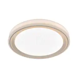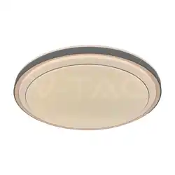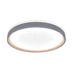
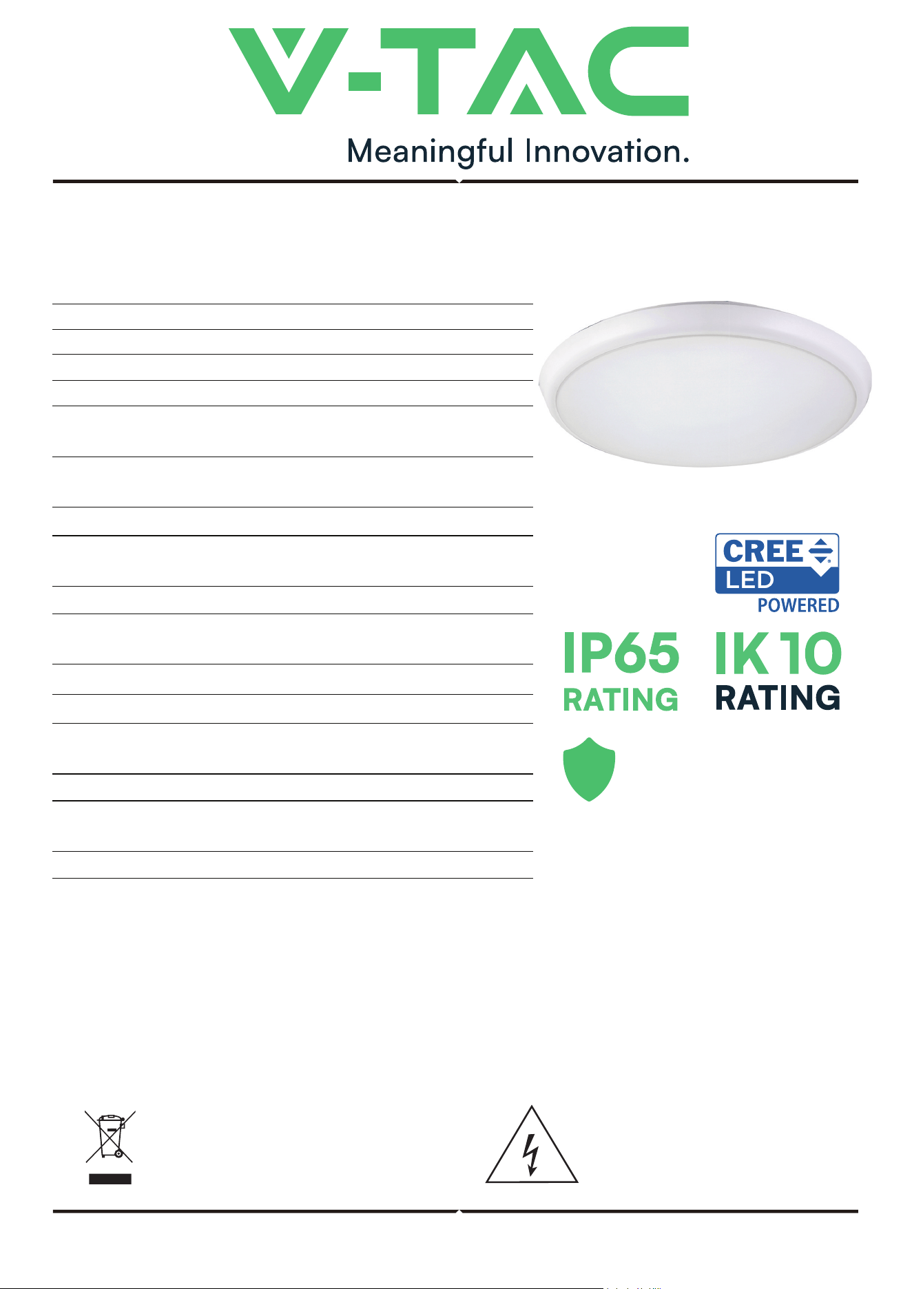
MICROWAVE SENSOR DOME LIGHT
TECHNICAL DATA
INTRODUCTION & WARRANTY
Thank you for selecting and buying V-TAC product. V-TAC will serve you the best. Please read these
instructions carefully before starting the installing and keep this manual handy for future reference. If you
have any another query, please contact our dealer or local vendor from whom you have purchased the
product. They are trained and ready to serve you at the best. The warranty is valid for 6 years from the date
of purchase. The warranty does not apply to damage caused by incorrect installation or abnormal wear
and tear. The company gives no warranty against damage to any surface due to incorrect removal and
installation of the product. The products are suitable for 10-12 Hours Daily operation. Usage of product for
24 Hours a day would void the warranty. This product is warranted for manufacturing defects only.
IN CASE OF ANY QUERY/ISSUE WITH THE PRODUCT, PLEASE REACH OUT TO US AT: [email protected] FOR
MORE PRODUCTS RANGE, INQUIRY PLEASE CONTACT OUR DISTRIBUTOR OR NEAREST DEALERS. V-TAC
EUROPE LTD. BULGARIA, PLOVDIV 4000, BUL.L.KARAVELOW 9B
This marking indicates that this
product should not be disposed
of with other household wastes.
Caution, risk of electric shock.
INSTRUCTION MANUAL
MODEL
SKU
DETECTION RANGE
INPUT VOLTAGE
POWER
TIME DELAY
AMBIENT LIGHT
DETECTION DISTANCE
INSTALLATION HEIGHT
HF SYSTEM
TRANSMISSION POWER
COLOR
TEMPERATURE
2700K, 3000K, 4000K,
5000K, 6500K (Adjustable)
8mW
STAND-BY PERIOD
0s, 90s, 5min, 10min,
30min, +∞(adjustable).
24GHz CW radar, ISM band
Wall : 1.5 - 3.5m
Ceiling : 2 - 4m
Wall : 1-5m (Adjustable)
Ceiling : 1-4m (Diameter), adjustable
<3-2000LUX (Adjustable)
Min. 10sec±3sec
Max. 12min±1min
20W, 25W, 30W, 35W, 40W
(Adjustable)
220-240V/AC,50/60Hz
360°
24360
VT-8179
DETECTION SPEED
0.6-1.5m/s
STAND-BY DIMMING LEVEL
7%
DIMENSION
Ø360x51mm
6
6 YEAR
WARRANTY*
FUNCTION
WARNING
• Please make sure to turn o the power before starting the installation.
• Installation should only be done by a certified electrician.
• Do not install the unit on uneven or unstable surfaces.
• Ensure there are no obstructions in front of the sensor that could interfere with detection.
• Avoid installation near metal or glass surfaces, as they may aect sensor performance.
• For safety reasons, do not open the casing if any malfunction is detected aer installation.
MULTI-LANGUAGE
MANUAL QR CODE
Please scan the QR code
to access the manual in
multiple languages.
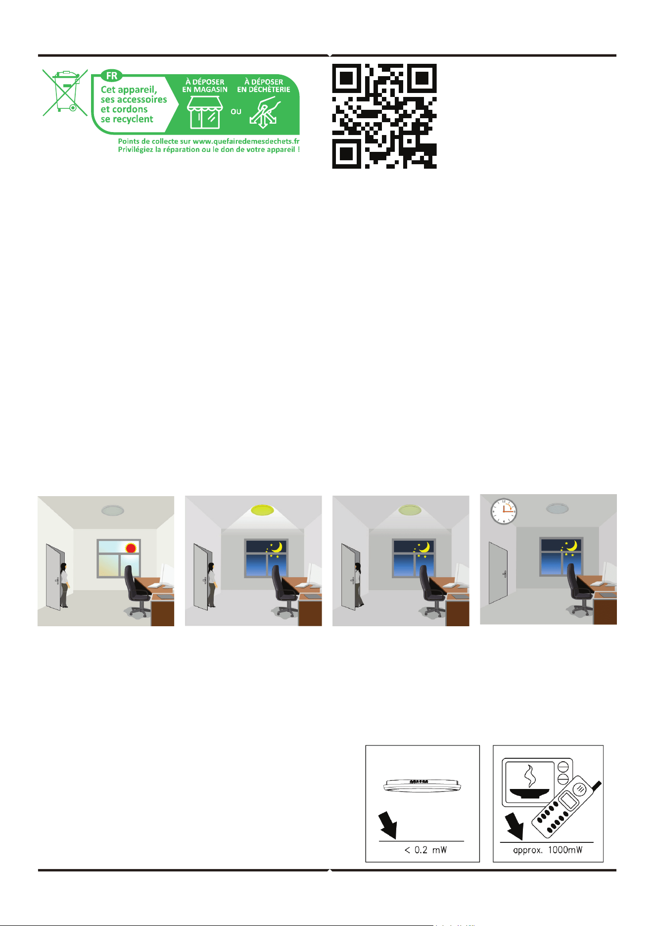
1. With ambient light more than daylight threshold, the lamp does not switch on when
someone enters the room.
2. With ambient light less than daylight threshold, the lamp will be on 100% when
someone enters the room.
3. People le, light dims to 7% (optional) stand-by level aer hold time.
4. Light switches o automatically aer the stand-by period elapsed.
NOTE: the high-frequency output of the HF
sensor is 8mW- that is just one 125th of the
transmission power of a mobile phone or
the output of a microwave oven.
Fig 1 Fig 2 Fig 3 Fig 4
• Can identify day and night: It can work in the daytime and at night when it is adjusted to the “sun” position (max). It
can work in the ambient light less than 3LUX when it is adjusted to the “3” position (min). As for the adjustment
pattern, please refer to the testing pattern.
• SENS adjustable: It can be adjusted according to using location; the detection distance of low sensitivity could be
only 2m and high sensitivity could be 8m which fits for large room.
• Time-Delay is added continually: When it receives the second induction signals within the first induction, it will
restart to time from the moment.
• Time-Delay is adjustable. It can be set according to the consumer’s desire. The minimum time is 10sec. The maxi-
mum is 12min.
• It oers 3 levels of light: 100 %--> dimmed light (7% optional) -->o; and 2 periods of selectable waiting time,
motion hold time and stand-by period; selectable LUX value and choice of detection area.
• The switch: 20W /25W /30W /35W /40W (Wattage adjustable), 2700K /3000K /4000K /5000K /6500K (5CCT
adjustable).
SENSOR INFORMATION
INSTALLATION INSTRUCTIONS
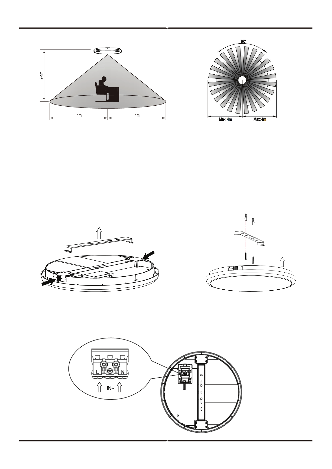
WIRING CONNECTION
1. Switch o the power supply before starting the installation.
2. Unscrew the terminal block cover at the bottom of the lamp and connect the wires according to the
wiring diagram.
3. Press the two side knobs to release the metal bracket (see Figure 1). Fix the metal bracket to the
ceiling using the supplied expansion screws (see Figure 2). Then press the lamp back onto the metal
bracket until it is securely fixed.
4. Switch on the power and test the lamp.
Height of installation: 2-4m Detection Area: Max. 8m
Figure 1 Figure 2
TEST
Note
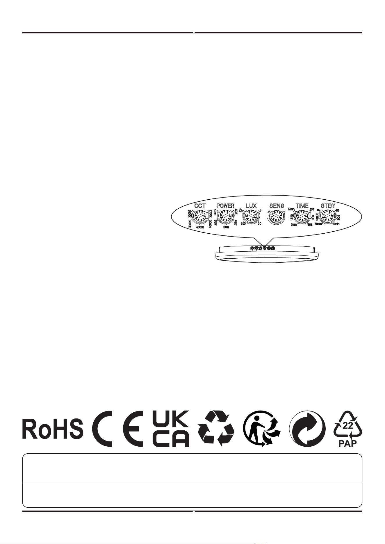
• You can turn the switch to adjust the wattage to 20W, 25W, 30W, 35W or 40W and the color temper-
ature to 2700K, 3000K, 4000K, 5000K, 6500K.
• Turn the LUX knob clockwise on the maximum (sun). Turn the SENS knob clockwise on the maximum
(+). Turn the TIME knob anti-clockwise on the minimum (10S). Turn the STBY knob anti-clockwise on
the minimum (0S).
• When you switch on the power, the lamp will be on at once. And 10sec±3sec later the lamp will be o
automatically. Then if the sensor receives induction signal again, it can work normally.
• When the sensor receives the second induction signals within the first induction, it will restart to time
from the moment.
• Turn LUX knob anti-clockwise on the minimum (3). If the ambient light is less than 3LUX (darkness), the
inductor load could work when it receives induction signal.
• Adjust the stand-by period to “90s”, when the sensor receives induction signal, the lamp will be 100%
on; 10sec later, the lamp dims quickly to 7% on for 90sec and then turn o. If the sensor receives
second induction signal within the stand-by period, the lamp will be 100% on.
• “+∞” indicates that the fixture remains at
the standby dimming level and does not
switch o.
• “0s” indicates that the dimming function
is disabled.
• When testing in daylight, ensure the LUX
knob is set to the SUN position; other-
wise, the sensor light will not operate.
TROUBLESHOOTING
• The load doesn’t work:
a. Check the power wiring.
b. Please check if the illuminance setting threshold corresponds to the ambient light.
c. Please check if the working voltage corresponds to the power source.
• The sensitivity is poor
a. Please check if in front of the sensor there shouldn’t be obstructive object that aect
to receive the signals.
b. Please check if the signal source is in the detection fields.
c. Please check the installation height.
• The sensor can’t shut automatically the load
a. If there are continual signals in the detection fields.
b. If the time delay is set to the longest.
V-TAC WEST EUROPE LTD. IN CASE OF ANY QUERY/ISSUE WITH THE PRODUCT, PLEASE REACH OUT TO US AT:
[email protected] FOR MORE PRODUCTS RANGE, INQUIRY PLEASE CONTACT OUR DISTRIBUTOR OR NEAREST DEALERS.
V-TAC WEST EUROPE LTD. GROUND FLOOR, 71 LOWER BAGGOT STREET, DUBLIN 02, IRELAND DO2 P593
V-TAC UK LTD. IN CASE OF ANY QUERY/ISSUE WITH THE PRODUCT PLEASE REACH OUT TO US AT
[email protected] V-TAC, 5A TUNGSTEN PARK, DOWNS ROAD, WITNEY, OXFORDSHIRE, OX29 0AX