Visit our website at: http://www.harborfreight.com
Email our technical support at: [email protected]
58001
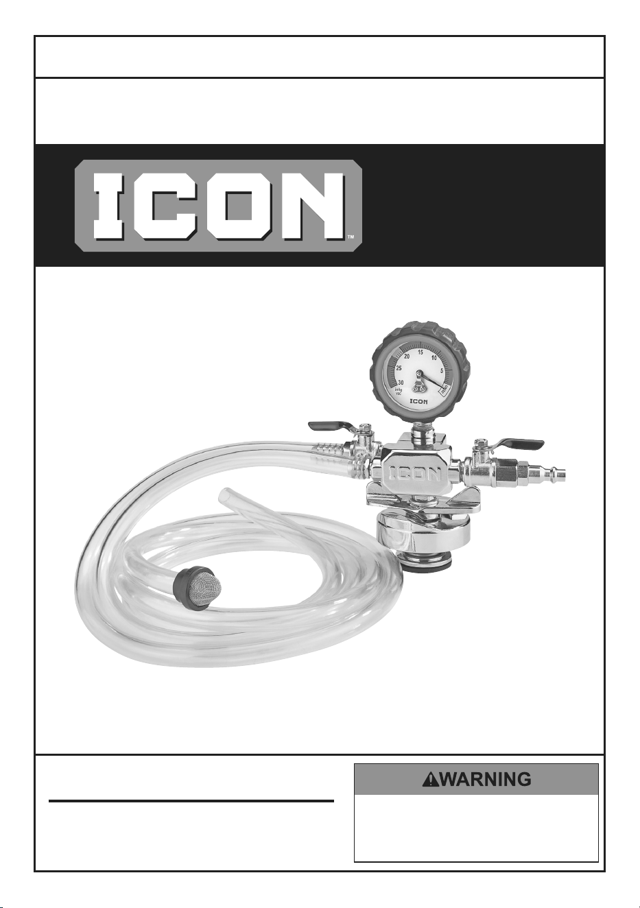
COOLING SYSTEM
FILLER AND TESTER
Owner’s Manual & Safety Instructions
Save This Manual Keep this manual for the safety warnings and precautions, assembly,
operating, inspection, maintenance and cleaning procedures. Write the product’s serial number in the back
of the manual near the assembly diagram (or month and year of purchase if product has no number). Keep
this manual and the receipt in a safe and dry place for future reference. 23h
When unpacking, make sure that the product is intact
and undamaged. If any parts are missing or broken,
please call 1-888-866-5797 as soon as possible.
Copyright
©
2022 by Harbor Freight Tools
®
. All rights reserved.
No portion of this manual or any artwork contained herein may be reproduced in
any shape or form without the express written consent of Harbor Freight Tools.
Diagrams within this manual may not be drawn proportionally. Due to continuing
improvements, actual product may differ slightly from the product described herein.
Tools required for assembly and service may not be included.
Read this material before using this product.
Failure to do so can result in serious injury.
SAVE THIS MANUAL.

Page 2 For technical questions, please call 1-888-866-5797. Item 58001
Important Safety Information
1. TO PREVENT STEAM BURNS, DO NOT
OPEN CAP OF HOT OR WARM RADIATOR.
2. Loosen the radiator cap slowly.
3. Keep away from hot engine parts and fluids.
4. Use this product only according to
these instructions. Improper use can
create hazards.
5. Wear ANSI-approved safety goggles
and heat resistant work gloves during
product assembly and use.
6. Refer to the vehicle’s service manual
for specific pressurized cooling system
testing instructions before use.
7. Clean up coolant spills immediately.
Dispose of fluids according to local, state,
and federal codes and regulations.
8. Keep work area clean and well lit.
9. Do not exceed 90 PSI maximum air pressure.
10. Do not overreach. Keep proper
footing and balance at all times.
This enables better control of the
product in unexpected situations.
11. Keep bystanders out of the area
during assembly and use.
12. Do not assemble or operate when
tired or when under the influence
of drugs or medication.
13. This product is not a toy.
Do not allow children to play
with or near this product.
14. Use as intended only.
15. Inspect before every use.
Do not use if parts missing or damaged.
16. Maintain product labels and nameplates.
These carry important safety information.
If unreadable or missing, contact
Harbor Freight Tools for a replacement.
SAVE THESE INSTRUCTIONS.
Page 3For technical questions, please call 1-888-866-5797.Item 58001
Setup - Before Use
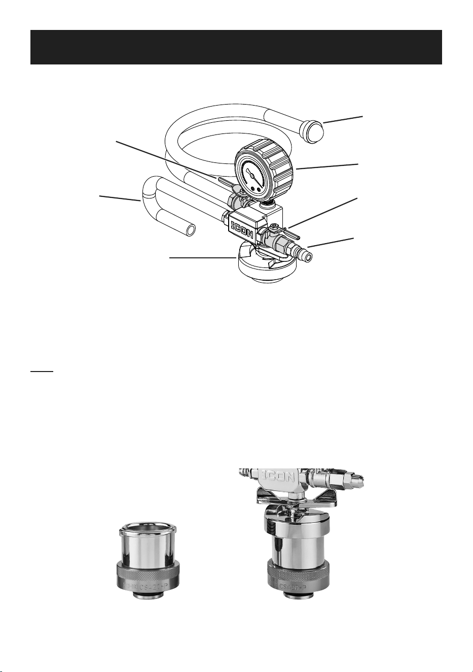
1. Install a 1/4″ NPT air fitting (not included)
into the inlet port on the Air Inlet Valve.
2. Connect the Coolant Refill Hose
and Overflow Hose to the tool.
Coolant Refill
Hose
Overflow
Hose
Radiator Cap
Air Fitting
(not included)
Air Inlet
Valve
Gauge
Coolant
Suction
Valve
3. Empty radiator of coolant and dispose
of or recycle old coolant properly.
4. Set the heater controls on the vehicle to the
highest heat position to ensure achieving
a vacuum on the entire cooling system.
Note: On some vehicles it may be necessary
to turn the ignition ON with the engine OFF
to open the heater control valves.
5. Loosen the vehicle’s radiator or coolant bottle
cap slowly to relieve any excess pressure
before removing the cap completely.
TO PREVENT STEAM BURNS, DO NOT
OPEN CAP OF HOT OR WARM RADIATOR.
6. The tool’s Radiator Cap will connect directly
to many older radiator filler necks. If it
does not, an adapter is needed. Use a
universal radiator adapter that relies on a
tight fit or an individual adapter designed for
your vehicle’s radiator or coolant bottle.
7. Wet the gasket with coolant before
installing the adapter on the tool. Align
the adapter ears with the opening on
the tool’s Radiator Cap. Press down on
the adapter and rotate until it stops.
Representative
adapter example
Adapter
installed
on tool

Page 4 For technical questions, please call 1-888-866-5797. Item 58001
Operating Instructions
1. Refer to vehicle’s service manual
for specific pressurized cooling
system testing instructions.
2. Connect tool (with adapter if needed)
to radiator or coolant bottle.
3. Close Coolant Suction Valve and Air Inlet
Valve, then attach the compressor air line to
the air fitting. Compressor must be capable
of supplying a constant 90 PSI to the tool.
4. Route the Overflow Hose to a bucket
to catch any residual coolant.
5. Route filter end of Coolant Refill
Hose down and away from vehicle’s
electrical components.
6. Make sure Coolant Suction Valve remains
closed. Start compressor and open Air
Inlet Valve to start drawing a vacuum. The
reading on the Gauge should start to rise.
Note: It may be necessary to close off the
overflow hose on some radiators or expansion
tanks to obtain a vacuum in the cooling system.
7. When Gauge reading stabilizes, continue
to draw vacuum for 30 seconds to obtain
maximum vacuum, typically -24 to -26 inHg
depending on coolant system size.
Note: Radiator and heater hoses may collapse
which is normal due to vacuum created.
8. Close Air Inlet Valve and monitor Gauge
reading for 1–2 minutes. If vacuum
drops, the cooling system has a leak
and is not sealed. Disconnect tool
and make necessary repairs.
9. Insert filter end of Coolant Refill Hose
into a container of premixed coolant.
10. Slowly open Coolant Suction Valve to purge
the Refill Hose of air — this will cause a
drop in vacuum. Close Coolant Suction
Valve once Refill Hose is filled with coolant.
11. Open Air Inlet Valve to increase vacuum
back to maximum level in the system.
Close Air Inlet Valve once achieved.
12. Open Coolant Suction Valve slowly. The
vacuum created will pull coolant into the
cooling system. Keep coolant container as
close as possible to same height as tool.
Important: Keep Coolant Refill Hose completely
submerged in coolant or air will be pulled into the
cooling system. If additional coolant is needed,
close Coolant Suction Valve and refill container.
13. When Gauge reaches zero, cooling system
is full. Disconnect compressor air line from
air fitting and remove tool from filler neck.
14. Check coolant level and top off if necessary.
Fill expansion tanks to proper level.
15. Store the Cooling System Filler and
Tester in its Case in a clean, dry, safe
location out of reach of children.

Page 5For technical questions, please call 1-888-866-5797.Item 58001
Maintenance and Servicing
Procedures not specifically explained in this manual must
be performed only by a qualified technician.
TO PREVENT SERIOUS INJURY FROM ACCIDENTAL OPERATION:
Detach the tool from the vehicle being tested before performing
any inspection, maintenance, or cleaning procedures.
TO PREVENT SERIOUS INJURY FROM TOOL FAILURE:
Do not use damaged equipment. If abnormal noise or vibration
occurs, have the problem corrected before further use.
1. BEFORE EACH USE, inspect the general
condition of the tool. Check for:
• loose fittings
• misalignment or binding of moving parts
• cracked or broken parts
• any other condition that may
affect its safe operation.
2. AFTER USE, clean external surfaces of
the tool with clean cloth and flush with
clean water. Allow the tool to air dry,
then store the Cooling System Filler
and Tester in its Case in a clean, dry,
safe location out of reach of children.
PLEASE READ THE FOLLOWING CAREFULLY
THE MANUFACTURER AND/OR DISTRIBUTOR HAS PROVIDED THE PARTS LIST AND ASSEMBLY
DIAGRAM IN THIS DOCUMENT AS A REFERENCE TOOL ONLY. NEITHER THE MANUFACTURER
OR DISTRIBUTOR MAKES ANY REPRESENTATION OR WARRANTY OF ANY KIND TO THE
BUYER THAT HE OR SHE IS QUALIFIED TO MAKE ANY REPAIRS TO THE PRODUCT, OR
THAT HE OR SHE IS QUALIFIED TO REPLACE ANY PARTS OF THE PRODUCT. IN FACT, THE
MANUFACTURER AND/OR DISTRIBUTOR EXPRESSLY STATES THAT ALL REPAIRS AND PARTS
REPLACEMENTS SHOULD BE UNDERTAKEN BY CERTIFIED AND LICENSED TECHNICIANS,
AND NOT BY THE BUYER. THE BUYER ASSUMES ALL RISK AND LIABILITY ARISING OUT OF
HIS OR HER REPAIRS TO THE ORIGINAL PRODUCT OR REPLACEMENT PARTS THERETO,
OR ARISING OUT OF HIS OR HER INSTALLATION OF REPLACEMENT PARTS THERETO.
Page 6 For technical questions, please call 1-888-866-5797. Item 58001
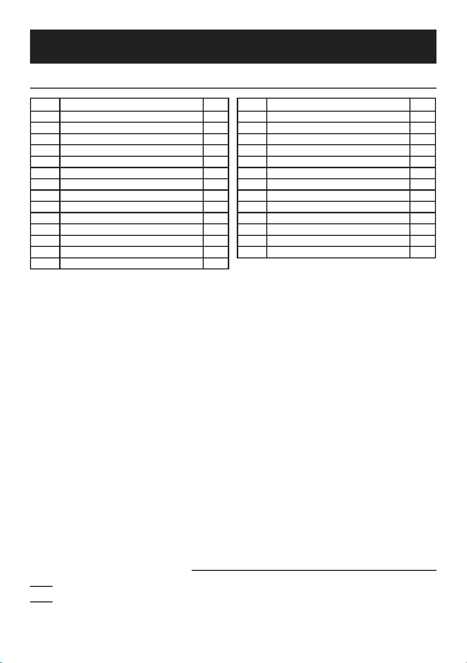
Parts List and Diagram
Parts List
Part Description Qty
1 Storage Case 1
2 Gauge Boot 1
3 Vacuum Gauge 1
4 Coolant Suction Valve 1
5 Hex Socket Head Cap Screw 2
6 Valve Body – Back 1
7 Piston 1
8 Release Valve Spring 1
9 Seal 1
10 Valve Body – Front 1
11 Inner Shaft 1
12 O-Ring 2
13 Barbed Fitting 1
14 Gasket 1
Part Description Qty
15 Air Inlet Valve 1
17 Spring 1
18 Radiator Cap Handle 1
19 Radiator Cap 1
20 Radiator Cap Inner Sleeve 1
21 Round Head Screw 2
22 Valve Body Screw 1
23 Washer 1
24 Filter Adaptor 1
25 Attachment Ring 1
26 Filter 1
27 Hose –1500 mm 1
28 Hose –1000 mm 1
Record Product’s Serial Number Here:
Note: If product has no serial number, record month and year of purchase instead.
Note: Some parts are listed and shown for illustration purposes only, and are not available
individually as replacement parts. Specify UPC 193175430618 when ordering parts.
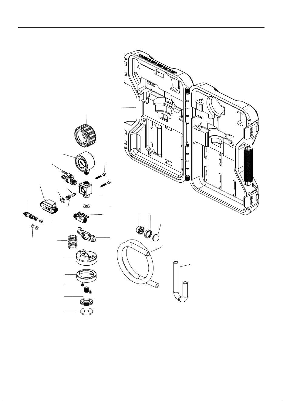
Page 7For technical questions, please call 1-888-866-5797.Item 58001
Assembly Diagram
1
2
3
5
6
7
8
9
11
12
15
18
17
19
20
22
23
24
28
4
10
13
14
25
26
27
21

26677 Agoura Road • Calabasas, CA 91302 • 1-888-866-5797
Limited Warranty
This ICON product is warranted to the original purchaser to be free from defects in materials and workmanship for a period
of one (1) year beginning on the date of purchase (or product receipt, if later). To obtain warranty service, the product or part
must be returned to us with proof of purchase (e.g. in-store receipt or packing slip/invoice) and may require shipment by
purchaser to a service center at purchaser’s expense. If our inspection verifies a covered defect in materials or workmanship
during the warranty period, we will, at our option, repair or replace the defective product. We will return repaired products
within a reasonable time at our expense, but if we determine that there is no defect, or that the defect resulted from
causes not within the scope of our warranty, then we will return the product to you if you pay return shipping costs.
This warranty does not cover any failure or damage that we determine is due directly or indirectly to normal wear and tear,
misuse, use not for the intended purpose or not in accordance with the product manual, abuse, accident, rental, modification
or alteration, unauthorized repair, improper installation, neglect, lack of maintenance, or any other failure not arising from
defective materials or workmanship. Fraudulent returns or claims will be denied. The repair or replacement described in this
warranty shall be your sole and exclusive remedy. THIS WARRANTY IS EXCLUSIVE AND IN LIEU OF ALL OTHER EXPRESS
WARRANTIES, WRITTEN OR ORAL, AND ANY IMPLIED WARRANTIES ARE DISCLAIMED TO THE EXTENT PERMITTED
BY LAW AND OTHERWISE LIMITED TO THE DURATION OF THE EXPRESS WARRANTY HEREIN. HARBOR FREIGHT
SHALL NOT BE LIABLE UNDER ANY CIRCUMSTANCES FOR ANY INCIDENTAL, INDIRECT, SPECIAL, CONSEQUENTIAL,
OR PUNITIVE DAMAGES OR COSTS ARISING FROM THIS WARRANTY OR THE USE OF THIS PRODUCT. SOME
STATES DO NOT ALLOW LIMITATIONS ON HOW LONG AN IMPLIED WARRANTY LASTS OR THE EXCLUSION OR
LIMITATION OF INCIDENTAL OR CONSEQUENTIAL DAMAGES, SO THESE LIMITATIONS MAY NOT APPLY TO YOU.
THIS WARRANTY GIVES YOU SPECIFIC LEGAL RIGHTS, AND YOU MAY ALSO
HAVE OTHER RIGHTS WHICH VARY FROM STATE TO STATE.