INTRODUCTION
WEEE Number: 80133970
INSTRUCTION MANUAL
RECHARGEABLE LI - ION BATTERY SYSTEM
Thank you for selec�ng and buying V-TAC Product. V -TAC will serve you the best. Please
read these instruc�ons carefully & keep this user manual handy for future reference. If you
have any another query, please contact our dealer or local vendor from whom you have
purchased the product. They are trained and ready to serve you at the best.
For More products range, inquiry please contact our distributor or nearest dealers
In case of any query/issue with the product, please reach out to us at: support@v-tac.e
12683 RECHARGEABLE Li-ion BATTERY SYSTEM
(Aircooling/Outdoor)
u
.
V-TAC EUROPE LTD. Bulgaria, Plovdiv 4000, bul.L.Karavelow 9B
MULTI-LANGUAGE
MANUAL QR CODE
Please scan the QR code
to access the manual in
multiple languages.
SKU DESCRIPTION

1
CONTENT
1. Important information in the manual ............................................................................... 3
1.1 Scope....................................................................................................................... 3
1.2 Safety Description..................................................................................................... 5
2.O v e rvi e w ...................................................................................................................... 12
2.1 Product Intro............................................................................................................12
2.2 Appearance and Structure.......................................................................................14
2.3 Intelligent air cooling system....................................................................................20
2.4 Grounding Design................................................................................................... 22
2.5 Wiring Holes Design................................................................................................22
2.6 Working Principle.................................................................................................... 23
3.I n stall a tion ...................................................................................................................24
3.1 Installation Process................................................................................................. 24
3.2 Unpacking and Checking........................................................................................ 25
3.3 Selection of Installation Site.....................................................................................27
3.4 Transportation.........................................................................................................29
3.5 Installation Preparation............................................................................................31
3.6 Mechanical Installation............................................................................................ 35
4.E l e ctr i cal Co nne c t ion .............................................................................................. 37
4.1 Installation Process................................................................................................. 37
4.2 Wiring......................................................................................................................40
5.S y stem debu g ging .................................................................................................... 45
5.1 Startup check.......................................................................................................... 45
5.2 The system is turned on.......................................................................................... 45
5.3 The system shuts down ...........................................................................................46
6. OHL’S Use r Interface ...............................................................................................48
6.1 Main Interface ........................................................................................................48
6.2Alarm description and processing ..........................................................................48
6.3 Cell Voltage ........................................................................................................... 49
6.4 Cell Temperature ................................................................................................... 49
6.5 Heating Temperature .............................................................................................50
6.6 Relay Status .......................................................................................................... 50
6.7 Other ......................................................................................................................51
6.8 Set Up ....................................................................................................................53
7. Xiaodan Energy Storage App ......................................................................................... 55
7.1 App download .....................................................................................................55
7.2. Log in and register ................................................................................................56
7.3. Equipment distribution network ............................................................................59
7.4. App page ...............................................................................................................59
8 Maintenance ....................................................................................................................70
8.1 Maintenance Guide.................................................................................................70
8.2 Key Components Maintenance............................................................................... 73
2
9 Maintenance ....................................................................................................................76
IMPORTANT NOTES
This product contains battery type "Secondary" (rechargeable).
Electrical and electronic equipment that has become waste is known as old equipment/device. Old devices must not be disposed of with
other household waste.
Owners of old devices at the end of its service life must return the device by taking them to the collection points set up by public waste
disposal authorities or distributors. This return does not entail any costs for you.
Owners of old devices have an obligation to remove accessible batteries / rechargeable batteries as well as non-destructively removable
lamps from the old device prior to return. This does not apply if old devices are being prepared for reuse with the participation of a public
law firm.
Battery removal warning: The battery contained in this product must be removed only by professional personnel only. The battery must
never be removed by the end user, if not removed correctly it could damage the battery which could cause fire.
Batteries removed from an old electronic device should be disposed of separately. This return of battery does not entail any costs for you
and the user is obliged to return the battery.
Please make sure that this product is not powered on when removing the battery. Fire hazard! Avoid short-circuiting the contacts of a
detached battery. Do not incinerate the battery. Please handle the battery with Caution!
If electrical appliances or batteries are disposed of in landfills or dumps, hazardous substances can leak into the groundwater and get into
the food chain, damaging your health and well-being.
The symbol of "Crossed rubbish bins "indicates that this product should not be disposed of with other household wastes and must be
collected separately from unsorted municipal waste at the end of its service life.
Please use the link below to view the online directory of the collection and return
polnts:
https://www.ear-system.de/ear-verzeichnis/sammel-und-ruecknahmestellen
Label for Waste Electrical and Electronic
Equipment (WEEE) Directive (2012/19/EU)
Warning electric shock.
3
1.Important information in the manual
1.1 Scope
Summaries
Thank you for choosing the energy storage system product!
This document gives a description of the energy storage system OHA-100, including the features,
performance, appearance, structure, working principles, installation, operation and maintenance. etc.
Please save the manual after reading, in order to consult in the future.
The figures in this manual are just for illustration, details please take the actual product as standard.
Target Group
* User
* Technical support engineer
* Installation engineer
* Debugging engineer
* Maintenance engineer
Suitable Model
* OHA-100
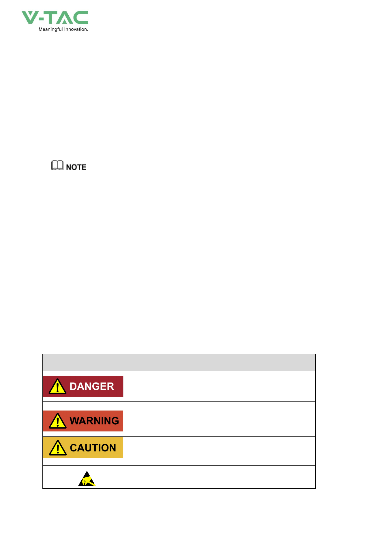
Symbol Conventions
The manual quotes the safety symbols, these symbols used to prompt users to comply with safety
matters during installation, operation and maintenance. Safety symbol meaning as follows.
Symbol
Description
Alerts you to a high risk hazard that will, if not avoided, result
in serious injury or death.
Alerts you to a medium low risk hazard that could, if not
avoided, result in moderate or minor injury.
Alerts you to a low risk hazard that could, if not avoided,
result in minor injury.
Anti-static prompting.

4
Be care electric shock prompting.
Provides a tip that may help you solve a problem or save
time.
Provides additional information to emphasize or supplement
important points in the main text.
Change History
Record the content of each document update. The latest version contains the updates of all previous
document versions.
Issue 01 (2025-11-05)
First issue.
5
1.2 Safety Description
This chapter mainly introduces the safety announcements. Prior to performing any work on the
device, please read the user manual carefully, follow the operation and installation instructions and
observe all danger, warning and safety information.
1.2.1 Safety Announcements
Before operation, please read the announcements and operation instructions in this section
carefully to avoid accident.
The promptings in the user manual, such as "Danger", "Warning", "Caution", etc. don't include all
safety announcements. They are just only the supplement of safety announcements when operation.
Any device damage caused by violating the general safety operation requirements or safety
standards of design, production, and usage will be out of guarantee range.
1.2.1.1 Safety Announcements
Damaged device or device fault may cause electric shock or fire!
* Before operation, please check if the device is damaged or has other danger.
* Check if the external device or circuit connection is safe.
Don't touch terminals or conductors that connected with grid to avoid lethal risk!
Please do not put finger or tool into the rotating fans to avoid human injury or device damage.
6
The product is grade A device. If the product is used in residential area, it may cause wireless
interference. User should take actions to avoid the interference.
1.2.1.2 Symbol Illustration
The warning labels on the energy storage system and in the cabinet include the important
information related to the device safe operation. DO NOT tear them up.
The illustration for the labels of energy storage system is as shown inTable1-1.
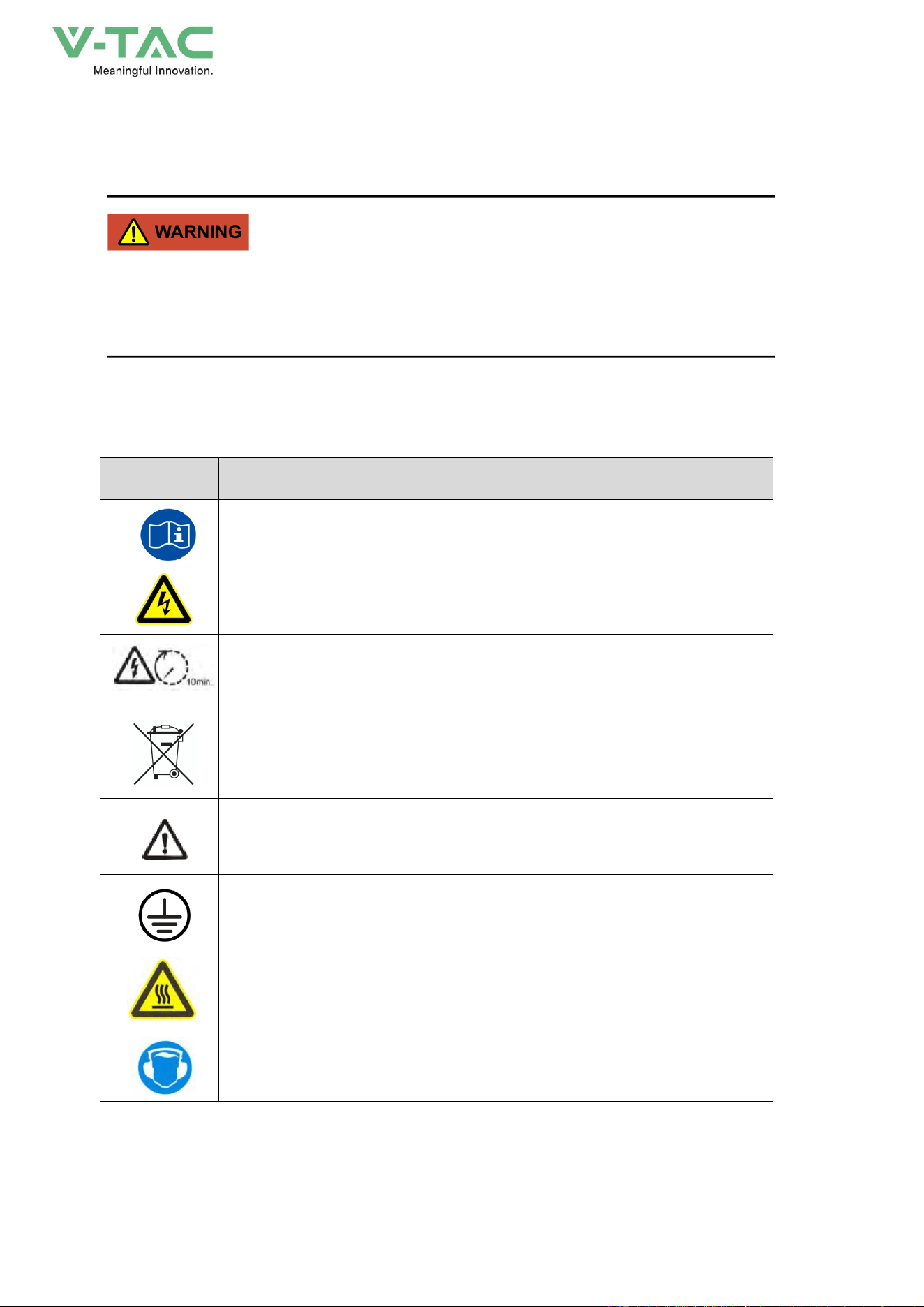
Table1-1 Symbol illustration
Symbol
Illustration
Observe the user manual.
There is dangerous voltage which may endanger human safety, be care
of electric shock.
After powering down, please wait for 10min to make the device discharge
completely.
Do not dispose the device together with the household waste but in
accordance with the disposal regulations for electronic waste applicable at
the installation site.
Pay attention to safety
External grounding mark. It needs to be connected with grounding to keep
the
operator safe.
Beware of hot surface. While operating, the temperature of air outlet
maybe high, do not touch the air outlet louver to avoid scald.
Take precautions against noise. Please wear the hearing protection
equipment.
7
1.2.1.3 Battery Use Announcements
Lethal high voltage exists in the negative and positive of energy storage batteries, touching by
accident will cause electric shock even endanger human safety.
When maintaining the device, make sure that the connection between the PCS and energy storage
battery has been disconnected completely. And set warning mark in the disconnected position to
avoid reconnecting by accident.
There is lethal high voltage between the positive and negative poles of batteries, DO NOT short
circuit the positive and negative poles, once short circuit, the battery will generate large current and
release a large number of energy, even cause battery thermal runaway, firing or explosion. To avoid
battery circuit, DO NOT maintenance the battery with electricity.
DO NOT place the battery under the environment where with high temperature or heating device,
such as resistance furnace, boiler etc. Battery over-temperature is easy to cause leakage, smoking,
releasing flammable gas, thermal runaway, firing or explosion.
DO NOT dismantle, transform or damage the battery (such as impale the battery with sharp object,
crush with dead weight or water logged, falling off, collision, etc.) to avoid causing electrolyte leakage,
smoking, release flammable gas, thermal runaway, firing or explosion.
DO NOT use the battery modules with different type together.
8
The battery electrolyte is toxic and with volatility. When the electrolyte is spilled or with abnormal
gas, please avoid touching the spilled electrolyte or gas. DO NOT approach unless professionals.
Please contact the professionals immediately to deal with it.
The gas generated from burning battery is harmful to eyes, skin and throat, please attention to the
protection.
Before installing the energy storage system, please configure the fire-fighting device according to
the construction standards, such as fire-fighting sands, carbon dioxide extinguisher, etc. Before
commissioning, ensure that the fire-fighting device has satisfied the requirements of local laws and
regulations.
Fasten the screws of copper bars and cables by specified moment of force, and check the screws’
condition regularly. The false connection of the screws will cause the connection voltage drop to be
too large, and even a large amount of heat will burn the battery when the current is large.
When first startup, if the battery temperature is too low, SOC saltation may occur at the end of charge and
discharge. The phenomenon is normal and not affect the normal operation. We suggest that keep the battery’s
temperature return to above 15℃ as far as possible and then start to discharge.
1.2.1.4 Grounding Requirements
High leakage risk! Device must be grounded before performing electrical connection. The
grounding terminal must be connected to ground.
* When installing, the device must be grounded first. When dismantling, the grounding wire must
be removed at last.
9
* Don't damage the grounding conductor;
* The device should be connected to the protection earth permanently. Before operation, it should
check the electrical connection to ensure the device is grounded reliably.
In the event of grounding fault in the energy storage system, some part that should not be charged
may have lethal voltage, and touch by accident will cause serious damage. Before installation and
operation, ensure that there is no system grounding fault and take appropriate protective measure.
1.2.1.5 Electrical Connection
The electrical connection must be performed strictly according to the description and wiring principle
diagram in the user manual and labels on the energy storage system.
The configuration and technical specifications (such as voltage, current, etc.) of energy storage
batteries, must meet the technical requirements of the energy storage system.
Grid-tied operation should be allowed by the local power supply department and the related
operation should be performed by professionals.
All electrical connection must meet the electrical standards of the country or local region where the
project located.
1.2.1.6 Measurement Under Operation
There exists high voltage in the device. If touching device accidently, it may cause electric shock.
So, when perform measurement under operation, operator must be accompanied by someone and
take protection measure (such as wear insulated gloves, etc.).
The measuring device must meet the following requirements:
* The range and operation requirements of measuring device meets the site requirements;
* The connections for measuring device should be correct and standard to avoid arcing.
1.2.1.7 ESD Protection
The static produced by human body may cause the sensitive components on the PCB damage.
10
* Avoid unnecessary touch for PCB.
* Wear an anti-static wrist strap before touching sensitive components, and the other end should
be well grounded.
1.2.1.8 APP Parameter Setting
Parameter setting is closely related to the operation of energy storage system, so the setting should
be performed after estimating.
* Improper parameter setting may affect the function of energy storage system.
* Only qualified professional can perform the parameter setting.
1.2.1.9 Moisture-proof and Sand-proof Protection
Moisture or sand incursion may cause the energy storage system damage!
Observe the following items to ensure the energy storage system works normally.
* When the air humidity is more than 95% or under the circumstance of sandstorm, strong wind,
hailstone, etc., don't open the door of the energy storage system.
* In the wet or damp weather, don't open the door of energy storage system to maintain or repair.
1.2.1.10 Safety Warning Mark Setting
In order to avoid accident for unwanted person getting close to inverter system or makes improper
operation, it should observe the following requirements when perform installation, daily maintenance
or repair.
* Set warning marks at the battery connection and grid connection of energy storage system to
avoid switching on the breakers improperly.
* Set warning signs or safety warning belt in the operation area, which is to avoid unwanted
person entering and cause human injury or device damage.
* After maintenance, ensure that pull out the key of energy storage system and save it properly.

11
1.2.2 Operator Requirements
The operation and wiring for energy storage system should be performed by qualified person, and
ensure the electrical connection meets the related standards.
Before installing, operating and maintenance, the operator must understand the safety
announcements, know correct operations and be trained strictly. The operator should meet the
following requirements.
* With a certain knowledge of electrical connection, mechanical installation, and familiar with the
electrical and mechanical principle.
* Be fully familiar with the constitution and operating principle of whole energy storage system.
* Be familiar with the structure and operating principle of connected device of energy storage
system.
* Trained by professional electrical operation, installation and debugging.
* Can handle with the emergency conditions while installing, debugging.
* Be familiar with the related country and district standard.
* Be familiar with the illustrations in the user manual.
1.2.3 Others
* For the energy storage system are also installed far away from downtown, please prepare the
emergency rescue facilities in advance.
* Take all possible auxiliary measures to ensure the safety of personnel and device.
12
2.Overview
2.1 Product Intro
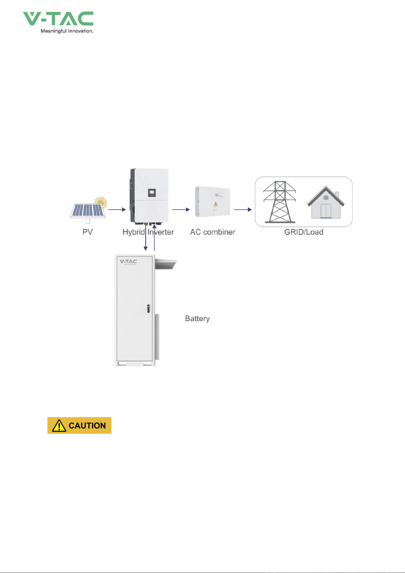
This product is a battery energy storage system with a system capacity of 100kWh. The energy
storage battery, temperature control system and fire protection system form an integrated system.
The output end is connected to an inverter, which combines photovoltaic and mains power to charge
and discharge the battery, achieving energy storage and backup functions. It can be applied to small
and medium-sized commercial places (stores, supermarkets, delis, hospitals, etc.), small and
medium-sized factories and charging stations, etc.
Figure2-1 Energy storage system constitution
Grid-tied operation of energy storage system needs to obtain the permission of local power supply
department and performed by professionals.
2.1.1 Features
Innovative Structure Design
* With small volume, high power density, the footprint is small.
* The modules adopt front pull-out maintenance, easy to replace.

13
Safe and Reliable
* Double fire-fighting of Pack and system.
* Three-level explosion-proof of cell, pack and energy storage system.
* Two-level BMS safe redundancy management, ensure the battery operating safely.
Smart Management
* Smart liquid-cooling, perfect heat dissipation, effectively decrease the temperature different
and enhance the battery use ratio.
* System adopts multi-level linkage design to achieve smart control and protection.
2.1.2 Technical data
Table2-1
Model
OHA-100
Main Parameter
Cell Chemistry
LiFePO4
Module Energy (kWh)
14.33
Module Nominal Voltage (V)
51.2
Module Capacity (Ah)
280Ah
Battery Module Qty In Series
(Optional)
7
System Nominal Voltage (V)
358.4
System Operating Voltage (V)
336.0~403.2
System Energy (kWh)
100.35
System Usable Energy (kWh)
90.31
Recommend Charge/Discharge
Current (A)
100
Max Charge/Discharge Current (A)
140
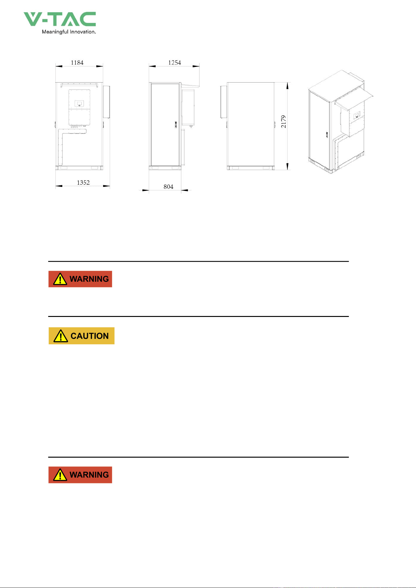
Dimension (W/D/H,mm)
895*1367*2179(Inverter not included)
1120*1367*2179 (Inverter included)
Weight Approximate (kg)
~1395
Installation Location
Floor-mounted
14
Cooling method
Smart Fan(PACK)
Communicaiton
CAN
Ingress Protection
IP55
Altitude
≤2000m
Cycle Life
25±2°C,0.5C/0.5C,EOL70%≥6000
Monitoring Parameters
System voltage,Current,cell voltage,cell temperature,module temperature
SOC
Intelligent algorithm
Working Temperature
-20℃ ~55℃
Storage Temperature
0~35℃
2.2 Appearance and Structure
2.2.1 Appearance
1
Figure2-2 Appearance
15
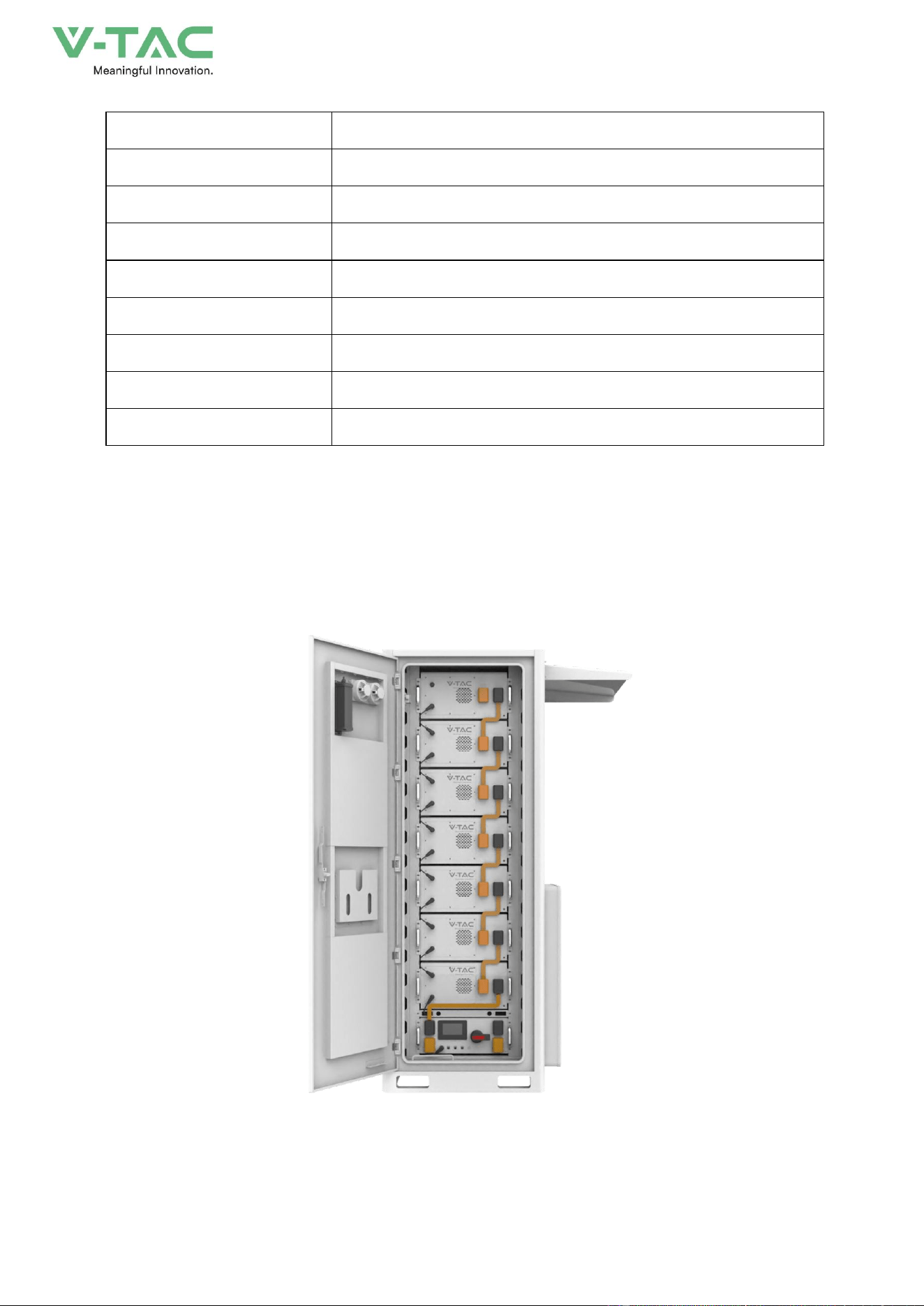
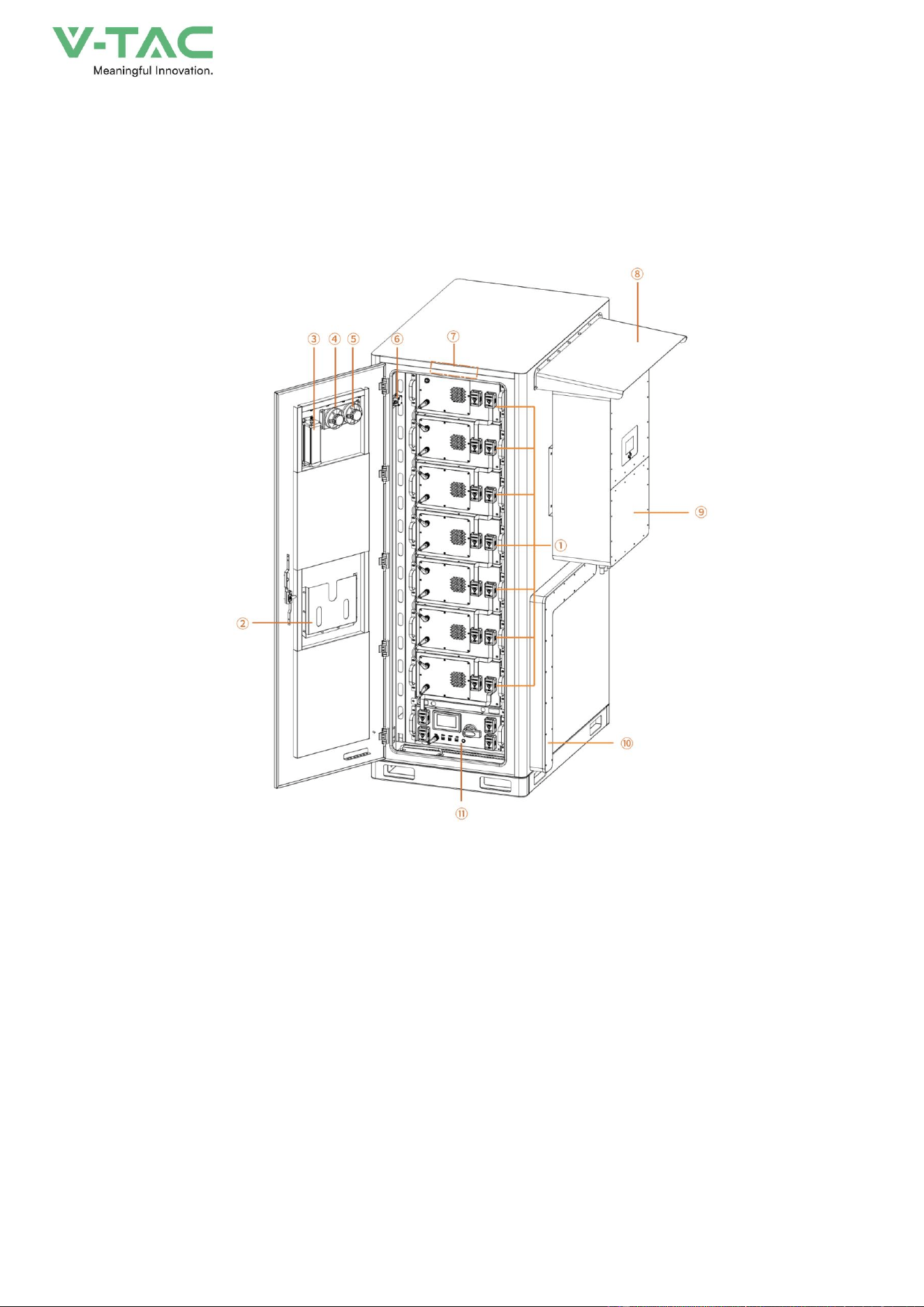
2.2.2 Structure Layout
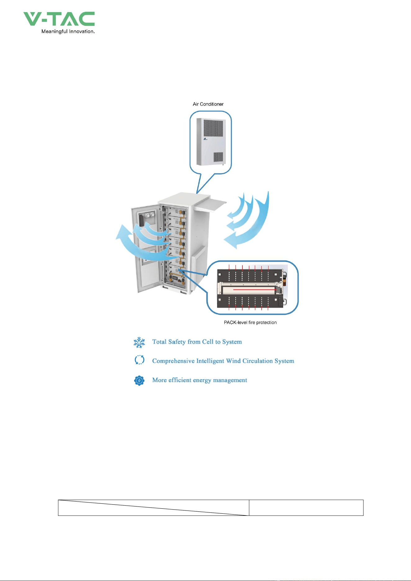
The energy storage system consists of a battery pack, a high-voltage box, an air conditioner, a
cabinet, aerosols, and a power distribution system. The structural layout is shown in Figure 2-3, and
the corresponding components are described in Table 2-2
Figure2-3 Structure layout (open the front door)
16
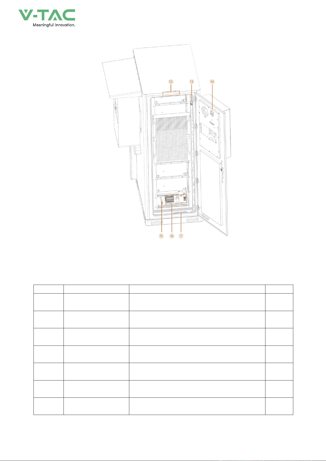
Figure2-4 Structure layout (Open the back door)
Table2-2Structure layout illustration
NO.
Name
Description.
Position
①
Lithium Iron Phosphate
Battery
51.2V280Ah
Front
②
document bag
Used for instruction manuals and inspection records
Front
③
Aerosol firefighting
Used to protect battery clusters from combustion
Front
④
smoke detector
Used to detect battery compartment fire
Front
⑤
temperature detector
Used to detect whether the battery compartment has
abnormal temperature
Front
⑥
limit switch
Used to control the switch of the light
Front
⑦
light
Used for illuminating battery compartment
Front
17
Rechargeable Li-ion Battery Module
Figure2-5 Structure layout
Table2-3 Structure layout illustration
⑧
Rain cover
Used to shield the inverter from rainwater
side
⑨
inverter
Due to the conversion of energy storage DC to AC
(customer supplied)
side
⑩
Cable tray
Wire slots for inverter incoming and outgoing lines
side
⑪
High voltage box
Used to control the current of the battery pack and
detect information about the battery pack
Front
⑫
light
Used for illuminating battery compartment
behind
⑬
limit switch
Used to control the switch of the light
behind
⑭
air conditioner
Used to balance the temperature inside the energy
storage cabinet
behind
⑮
Zero line Bus bar
Used for electrical neutral circuit
behind
⑯
Control board
Used to control the switches of energy storage cabinet
air conditioning, lights, etc
behind
⑰
Ground bus bar
Used for grounding electrical equipment
behind
18
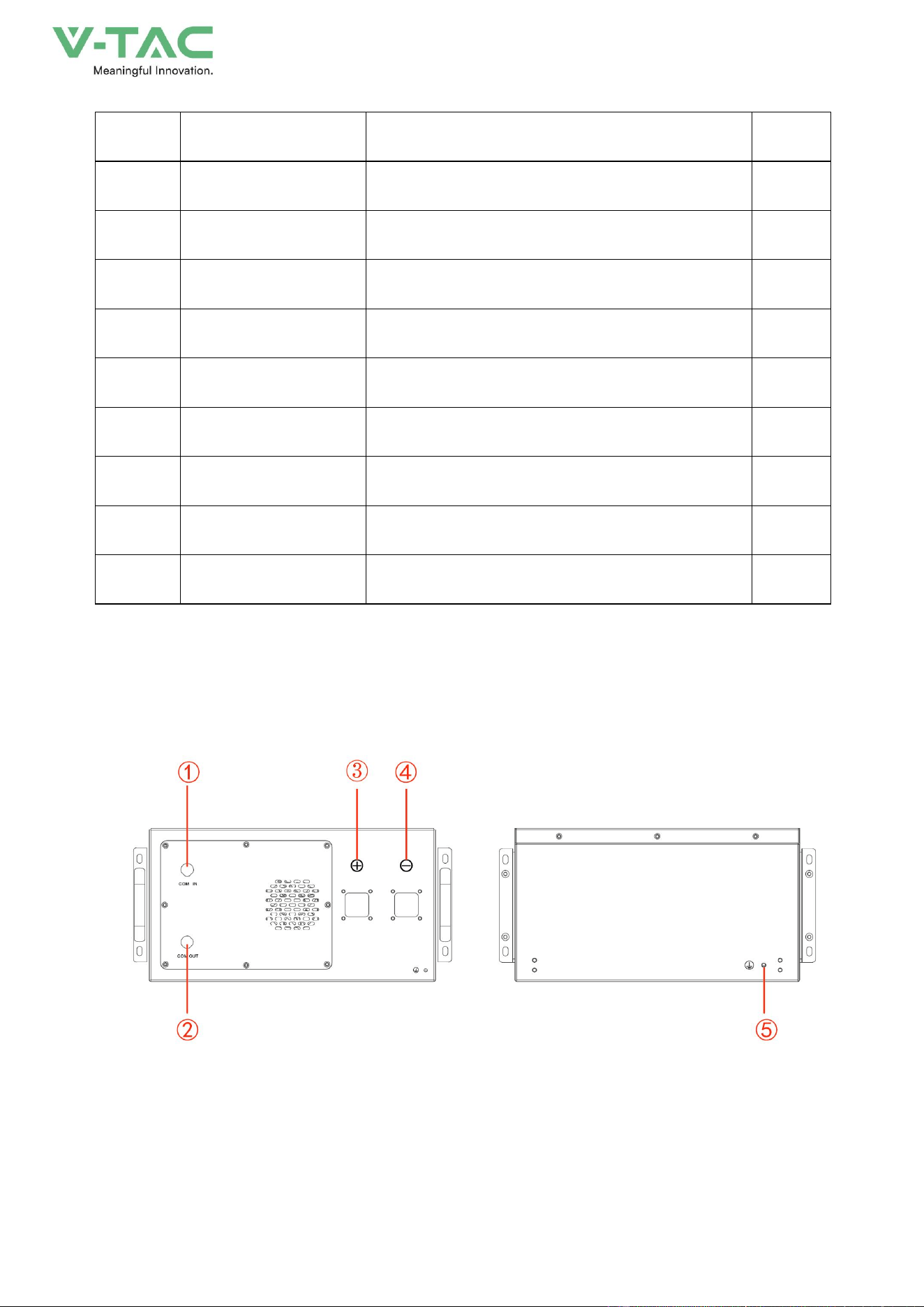
High voltage battery cluster control box
Figure2-6 Structure layout
NO.
Name
Description.
Position
1
COM IN
Connection position of battery module communication
supply input or output.
Definition:
1:P-IN、2:IM-IN、3:FAN+、4:FAN+、5:FAN-、6:FAN-
Front
2
COM OUT
Connection position of battery module communication and
power supply input or output.
Definition:
1:IP-OUT、2:IM-OUT、3:FAN+、4:FAN+、5:FAN-、6:FAN-
Front
3
B+
Battery module positive pole (orange)
Front
4
B-
Battery module negative pole (black).
Front
5
Earthing wire
Battery module grounding location
behind
19
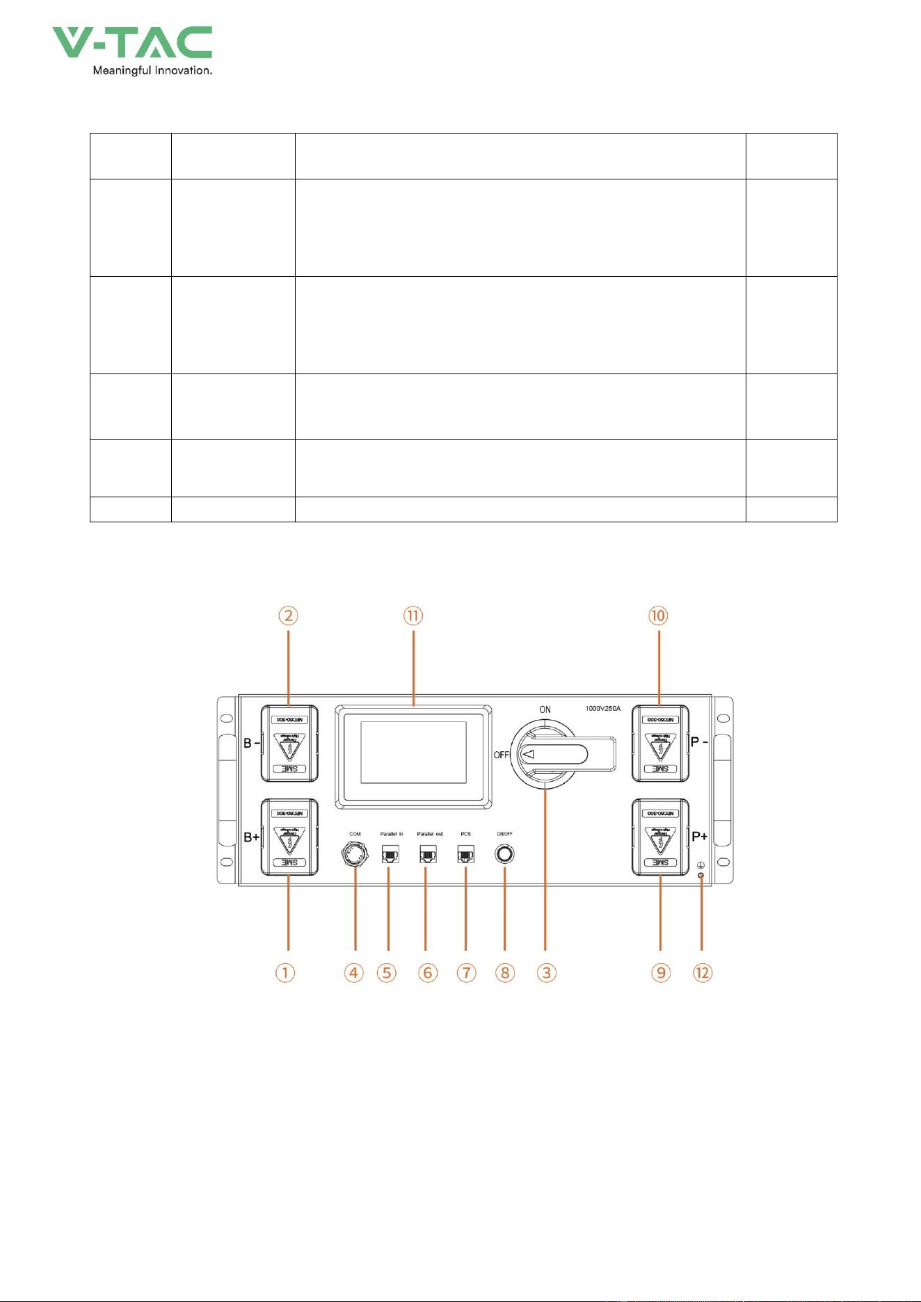
Figure2-7 Structure layout
Table2-4Structure layout illustration
NO.
Name
Description.
Position
①
B+
High voltage box module positive pole (orange)
Front
②
B-
High voltage box module negative pole (black).
Front
③
Air switch
Used to manually control the connection between the
battery rack and external devices.
Front
④
COM
Communication port between battery and high-voltage box
Definition:
1:ISOPSPI_H、2:ISOPSPI_L、3:FAN+、4:FAN+、5:FAN-、
6:FAN-
Front
⑤
Parallel in
Parallel communication input port
Definition:
1:GND、2:GND、3:CAN1G、4:CAN1H、5:CAN1L、6:DIG_IN2
Front
⑥
Parallel out
Parallel communication output port
Definition:
1:GND、2:GND、3:CAN1G、4:CAN1H、5:CAN1L、6:HSS1
Front
⑦
PCS
Inverter communication port
Definition:
1:RS485A_1 、 2:RS485B_1 、 3:CAN1G 、 4:CAN1H 、
5:CAN1L、6:RS485G_0、7:DEBUG CANH、8:DEBUG CANL
Front
⑧
ON/OFF
BMS start button and Green indicator light
Front
⑨
P+
Connect the high-voltage box to the positive pole of the
inverter
Front
⑩
P-
Connect the high-voltage box to the negative pole of the
inverter
Front
⑪
Human-machine
interface (HMI)
Display some important battery information.
Front
⑫
Earthing wire
Battery module grounding location
Front
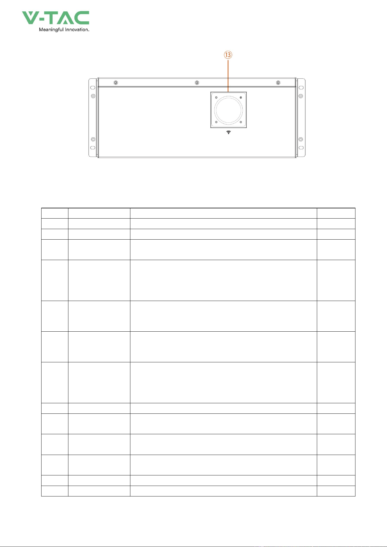
⑬
WiFi
High voltage box WiFi signal antenna
Rear
20
2.3 Intelligent air cooling system
2.3.1 System principle
Figure2-8 System schematic diagram
2.3.2 Specifications
Parameter Specifications (The temperature setting for the air conditioner can be found in the
"Air Conditioner for Outdoor Electricity Cabinet User Manual".)
The parameter specifications of the MC20HDNC1A chillers are shown in Table 2-5.
Table 2-5 Parameter specifications
Parameter Model
MC20HDNC1A

21
Dimensions, Weight & Mounting Method
Dimension(W×D×H)
mm
495×195×795
Weight(without coolant)
kg
32
Installation Method
Horizontal Embedded
Application
Door decoration
Environmental Protection & Performance
Working Temperature Range
℃
-40~+25
(
heating
)
-15~+55
(
refrigeration
)
Noise Level@1m
dB(A)
65
Appearance
RAL7035 Outdoor
IP Protection Level
IPX5
Refrigerant
R134a
RoHS Compliant
Yes
Design Lifetime
Year
10
Cooling/Heating Capacity
Cooling Capacity@W18/L35
kW
2.0
Heating Capacity@Tu=10
℃
kW
1.0
Power Consumption
Cooling Input Consumption@L35/L35
kW
0.78
Cooling input current @ L35 L35
A
3.6
Air Volume
Internal Circulation Air Volume
m³/h
380
Power Supply
Rated Operating Voltage
V, Hz
220±15%,50Hz
Power Supply Range
V, Hz
220±15%,50Hz
Max. Operating Current
A
5.0
22
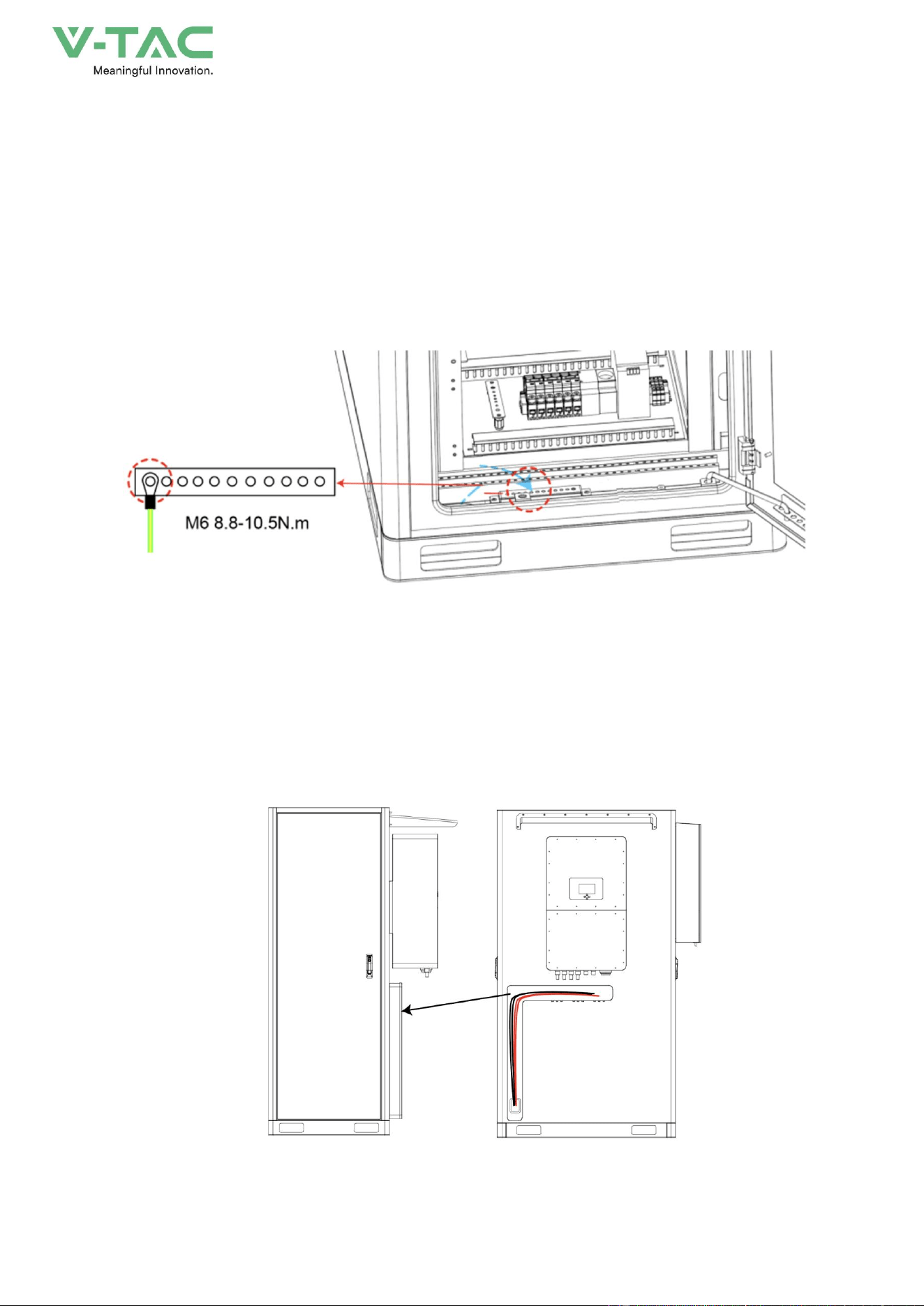
2.4 Grounding Design
There are 1 external grounding terminals at the front and back of energy storage system, as shown
in Figure2-9.
Figure2-9 Cabinet grounding terminals diagram
2.5 Wiring Holes Design
The connection wires between the energy storage system and the inverter have been pre connected.
You just need to open the wire trough cover and take them out.
Figure2-10 Inside the wire trough
23
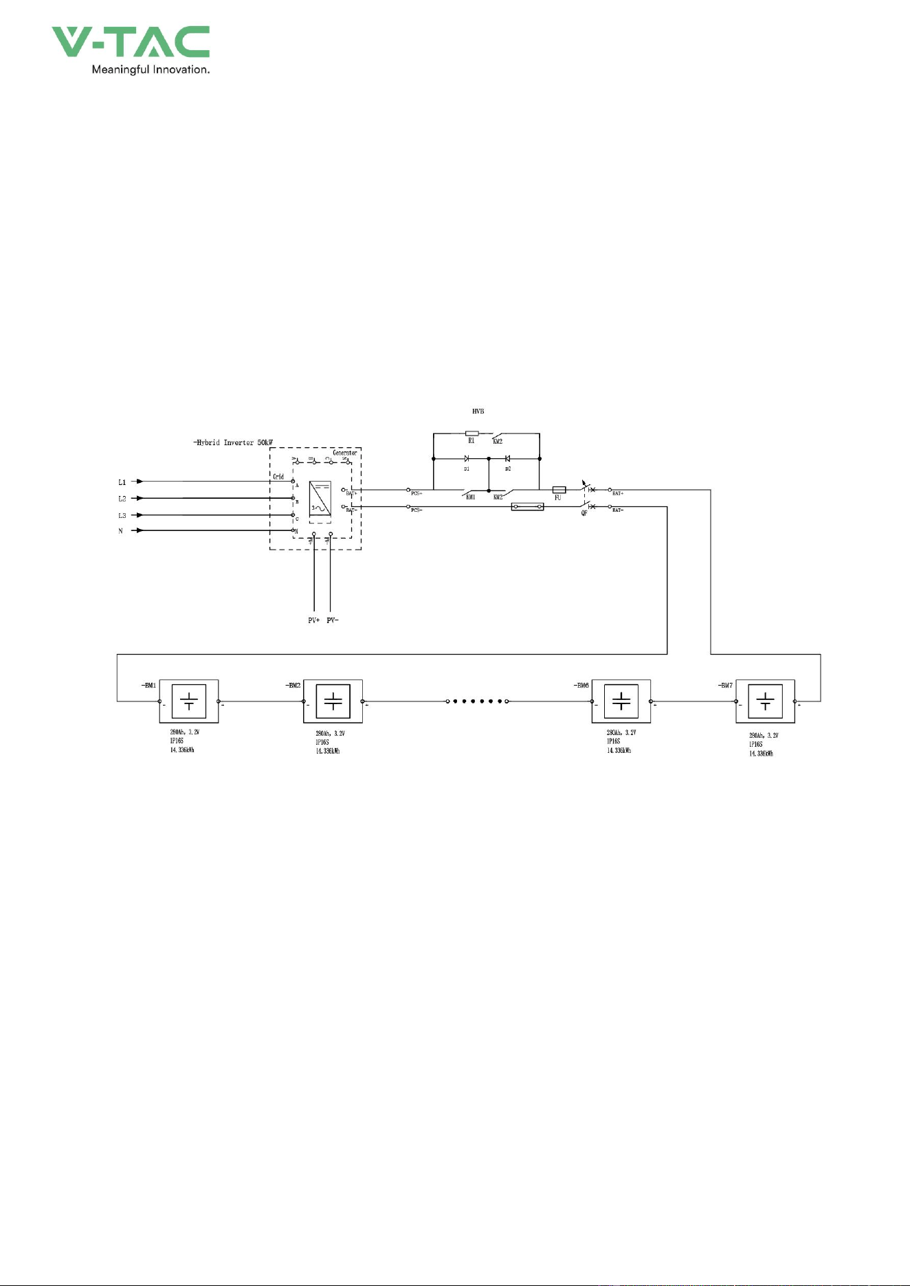
2.6 Working Principle
The energy storage system consists of a 100kWh energy storage system, a temperature control
system and a fire protection system. The energy storage unit is composed of Seven air-cooled
battery packs, each consisting of 16 batteries with a cell capacity of 280Ah. Each energy storage
system is 1P112S and has a nominal capacity of 100kWh. During discharge, the DC output power of
the battery cluster is connected to the inverter through a DC circuit breaker, and then converted into
AC power and output to the power grid or load through an AC circuit breaker. When charging, the
power grid outputs alternating current to the inverter, which converts the alternating current into direct
current to charge the battery, or the photovoltaic direct current is directly used to charge the battery
through the inverter.
Figure2-13 Electrical schematic diagram
24
3.Installation
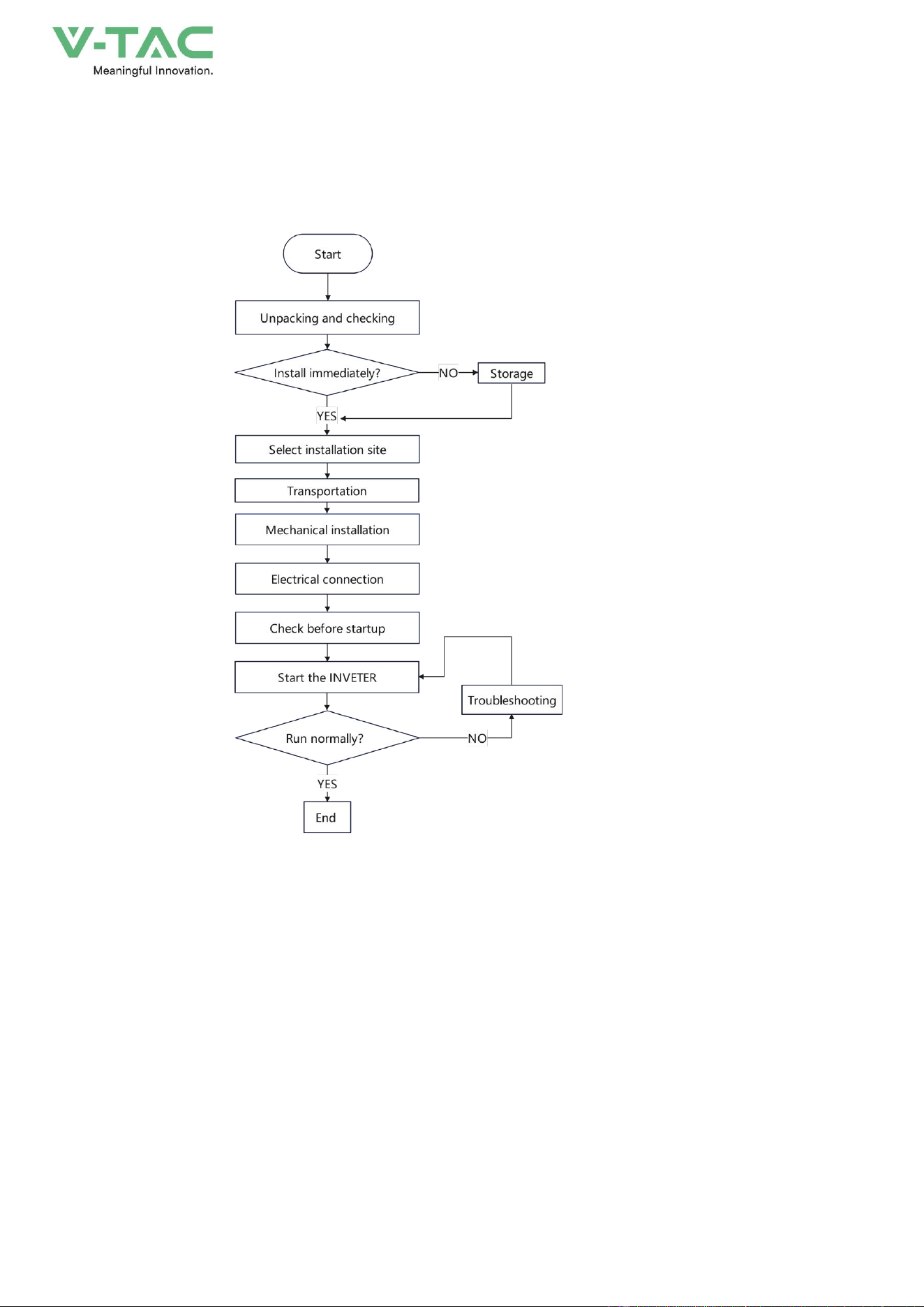
3.1 Installation Process
Figure3-1 Installation process
25
3.2 Unpacking and Checking
Determine the unpacking site in advance. Generally, the unpacking site should be as close to the
installation position as possible.
Check the External Package
The energy storage system has been completely tested and strictly inspected before leaving the
factory, but damage may still occur during transporting, so a detailed inspection is required after
arrival.
* Check the model, etc. of energy storage system (the delivering information can be find on the
label at the side of the package, position as shown in Figure3-2), ensure that the model is in
accordance with the ordered model.
* Inspect the package appearance for shipping damage, such as holes, cracks or other signs that
could cause internal damage.
* Rainy days maybe encountered during transporting, please check whether the energy storage is
flooded with rainwater.
If any shipping damage is found, do not open the package and contact the manufacturer immediately.
Check the Deliverables
Unpack the package, check if the types of the accessories are complete and correct. If there is
any discrepancy, take notes and contact the distributor immediately.
The name and quantity of deliverables, please see the packing list.
After unpacking, if the energy storage system will not be used immediately, please store it
according to following requirements.
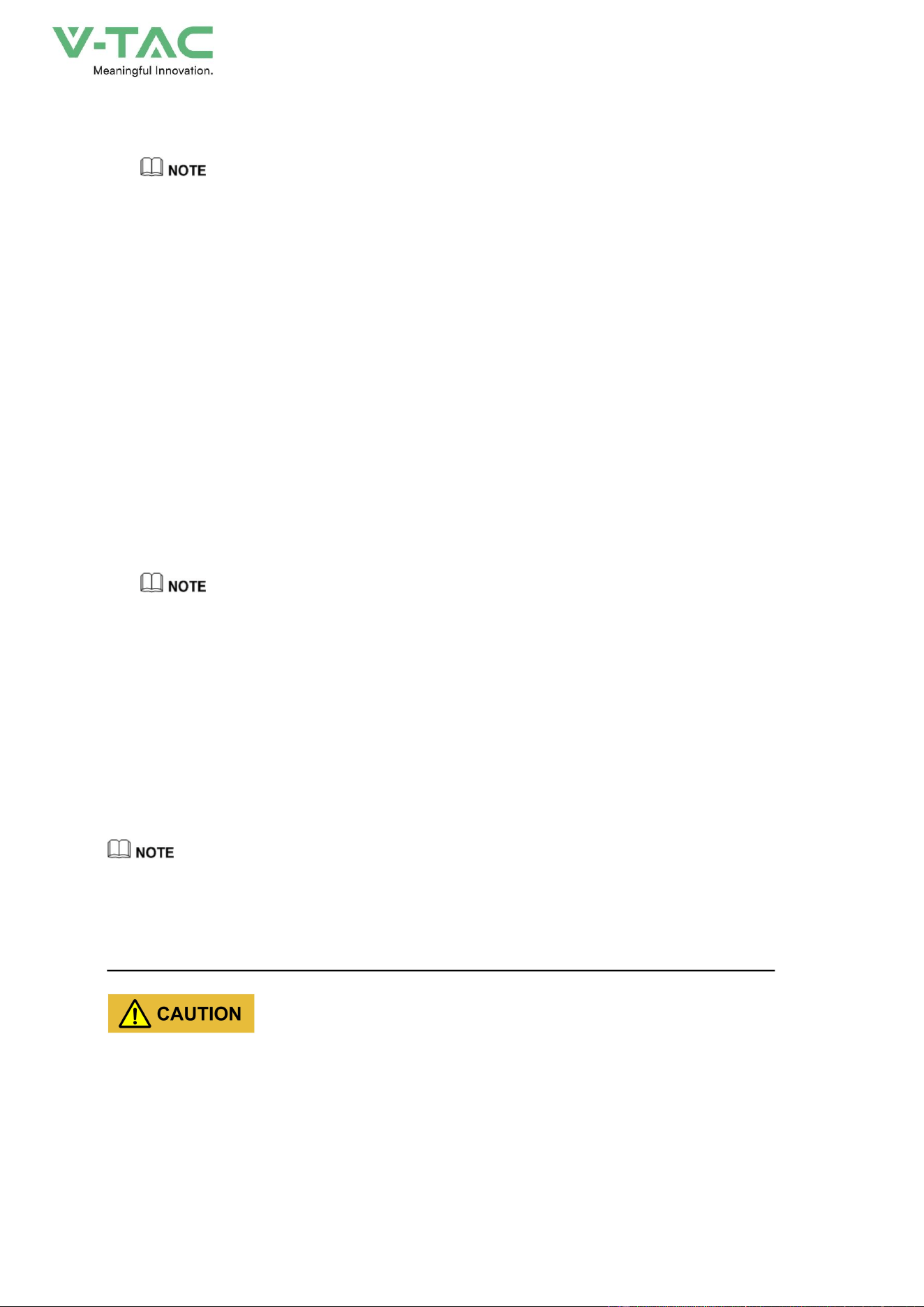
Please store the energy storage system on the basis of storage requirements. If the damage
caused by mismatch storage requirement, it will be out of warranty.
* Package the energy storage system by original package, keep the desiccator in the package
plastic bag, seal the inner plastic bag.
* The energy storage system should be placed in the place where is clean and dry and avoid
26
direct sunshine, rain or ponding, strong mechanical vibration, impact or strong electric field. No
corrosive or inflammable or explosive gas or object in the storage environment.
Figure3-3 Storage environment requirements
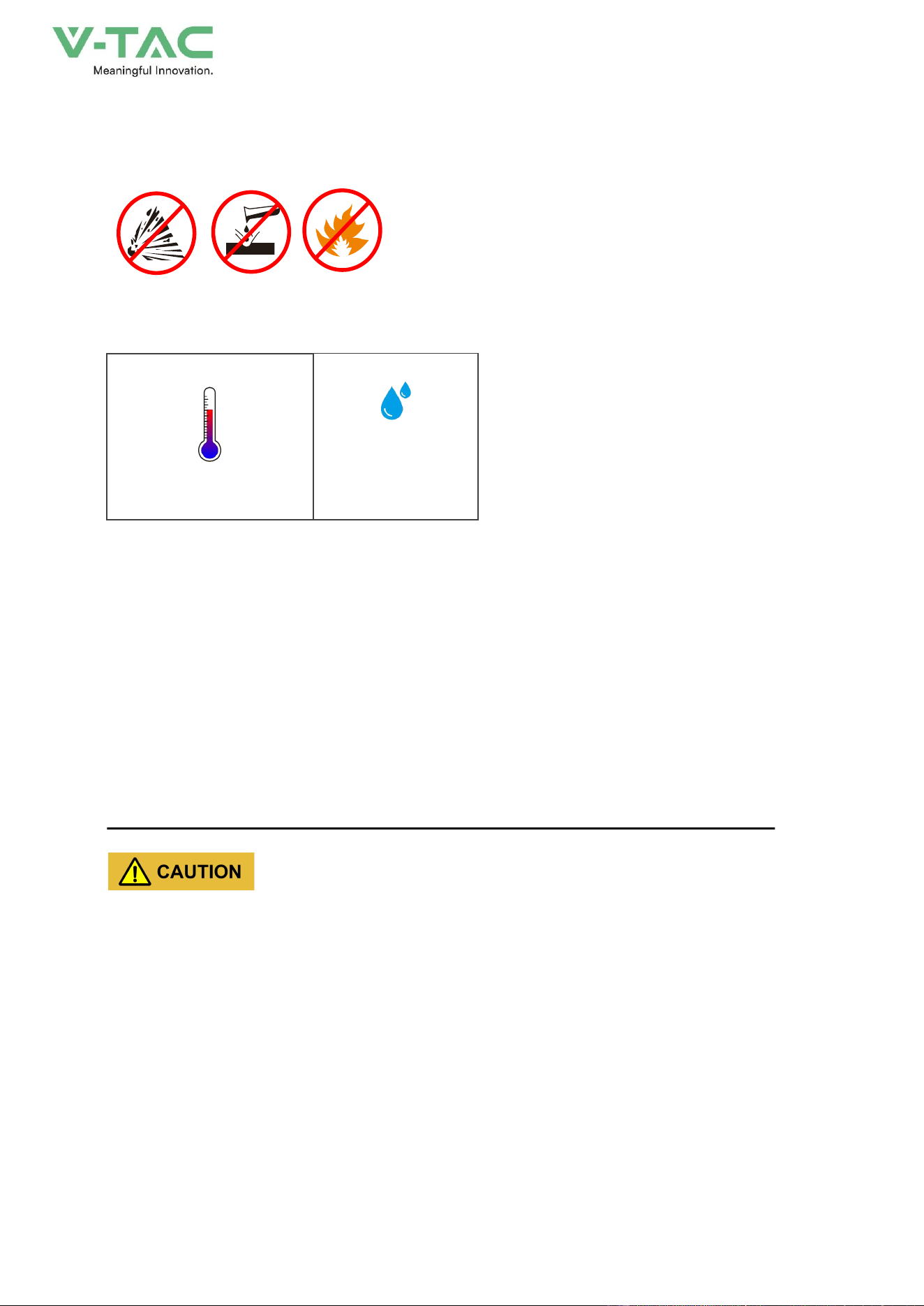
* Storage temperature: -20~45℃ (for long term storage, the temperature should be within the
range of 0~35℃, if the energy storage system is stored out of temperature range for long time, it will
affect the performance and service life of battery.
0℃~ 35℃ (long term)
0%~ 95%, without
condensation
Figure3-4 Storage temperature and humidity
* The placed direction of energy storage system should be accord with the marked direction on
the package. The package should be padded 20cm from the floor and keep at least 50cm away from
the wall, heat source, cold source, window or air inlet.
* When multi energy storage systems are stored, DO NOT stack them together.
* DO NOT tilt or invert the packed energy storage system.
* During storage, please check the energy storage regularly (we suggest checking it once every 3
months). If the package is damaged by insects or rats, please replace the package in time.
* Under the storage condition above, the storage period is 6 months. If the energy storage system
is stored over 6 months, the energy storage system should be checked and tested by professionals,
and then,it can be put into use.
From the date of delivery, every 6 months of storage, please recharge the energy storage system
according to the specified requirements .
When the energy storage system has entered or passed through a humid environment, it is
recommended to keep it in a dry and ventilated environment for more than 24 hours.
Before operation, perform an insulation impedance test. After the insulation impedance test is
passed, perform a voltage withstand test. Only after all the tests have been passed can the energy
storage system be operated.
If the insulation impedance test and voltage withstand test fail, continue to dry and ventilate the

27
energy storage system.
Generally, the energy storage system can operate normally after drying and ventilating twice.
* If the product needs to be transported again, please strictly pack it before loading it for
transporting.
3.3 Selection of Installation Site
When choosing an installation site, observe the following principles at least.
* The site where the energy storage system is placed should be solid and flat, well-drained, free of
obstacles or protrusions, and avoid sites with existing underground utilities.
* The site should be open or solid enough above the site, with no risk of water or foreign objects
falling on it.
* The surrounding environment of installation should be dry and well ventilated, and there should
be no flammable, explosive or corrosive substances. Keep away from areas where dust, fumes,
corrosive gases and noxious gases are generated.
* Do not install the energy storage system outdoors in salt damage areas.
Salt damage areas mainly refer to coastal areas within 500m from the coast. The precipitation amount of
salt spray varies greatly depending on the characteristics of seawater in the neighboring sea, sea breeze,
precipitation, air humidity, terrain and forest cover.
* Do not install the energy storage system in locations accessible to children.
* The installation location needs to meet the necessary traffic conditions and have a reliable fire
protection system.
* The energy storage system should be installed at a distance of no less than 12m from residential
buildings and greater than 30.5m from crowded places such as schools and hospitals.
* The distance between the energy storage system and the production building must meet local
fire codes or standards.
− The safety distance between the energy storage system and the Class A production building
should not be less than 12m.
− The safety distance between the energy storage system and the Class B production building
shall not be less than 10m.
− The safety distance between the energy storage system and the production buildings of class C,
D and E that meet the fire resistance rating of not less than grade II shall not be less than 10m.
− If the outer walls of two adjacent buildings are non-burning and there are no door or window
openings or exposed burning eaves, the fire separation distance can be reduced by 25% according to
the safety distance corresponding to each type of production building.
− If the safety distance of production buildings does not meet the requirements, a protective wall
with a fire resistance of at least 3 hours must be equipped for protection. The protection spacing is not
limited, and the length and height of the firewall should exceed the outer perimeter of the energy
28
storage system by at least 1m. At the same time, it is necessary to take into account the space
requirements required for various operations of the energy storage system.
* Installation space expansion conditions must be considered during the life cycle.
3.3.1 Installation Environment Requirements
According to the EMC and noise level, the energy storage system is used in an industrial
environment, and the installation site should be selected from an outdoor site away from the living area.
The installation environment requirements are as follows.
* Environment temperature: -20℃~+55℃.
* Relative humidity: 0%RH~95%RH, non-condensing.
* Altitude: 0m~3000m.
* Ensure that the installation site is well ventilated and free from excessive dust, acid, alkali,
corrosive and explosive particles and gases.
When the energy storage system is exposed to sunlight, the internal temperature rise will increase, which
may affect the charging and discharging performance, so it is recommended to install the energy storage system
with a sunshade or other sheltering facilities .
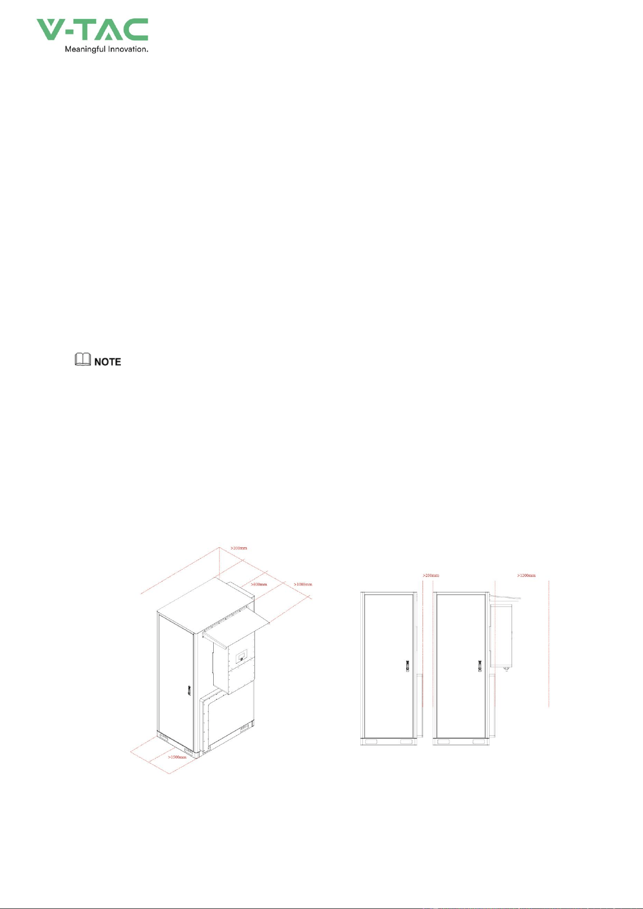
3.3.2 Installation Space
Reserve enough space around the energy storage system (as shown in Figure3-5) for installation,
operation, and maintenance, and normal ventilation. If allowed, it is recommended to leave more
space between the energy storage system and other devices or walls for heat dissipation and
maintenance, to ensure the stable and efficient operation of the energy storage system.
Figure3-5 Installation space (unit: mm)
29
3.3.3 External Fire-fighting Suggestion
* A fire-fighting water supply system should be provided at the installation site of the energy
storage system.
* Municipal water supply is preferred as the water source of fire-fighting, and fire-fighting water or
natural water supply may also be used. When natural water sources are used, reliable water intake
settings should be set.
* The designed flow of fire-fighting water supply shall be determined according to the sum of the
maximum designed flow of water extinguishing systems that need to act simultaneously. The water
consumption for fire-fighting shall be calculated according to the number of fires at the same time and
the maximum water consumption required for extinguishing a fire.
* External fire hydrant system design shall meet the following requirements:
− Fire hydrants should be evenly arranged along the roadside of the site. The distance between
the fire hydrants and the energy storage system should be not greater than 20m.
− Each energy storage system is recommended to have at least one fire hydrant, and the water
consumption of the fire hydrant should not be less than 20L/s.
− Anti-freezing measures should betaken against outdoor fire hydrants in cold areas.
− Outdoor fire hydrants should be provided with permanent fixed markings.
− Spray guns should be provided near the power distribution unit area.
− The station area should be set up with a dedicated fir room (box) equipped with a fire hose,
water gun and fire-fighting wrench.
3.4 Transportation
Please select suitable transportation device according to the weigh (<1.5t) and size (985mm ×
1367mm×2179mm (W×D×H), without inverter) of energy storage system.
When transporting on the installation site, the forklift or crane can be used to transport the energy
storage system.
In the process of loading,uploading and transporting, the operation safety regulations of
thecountry/region where the project is located must be obser ved.
Improper transporting operations may result in the device damage or personnel injury.
* The energy storage system must be carried by trained professionals and should be directed by a
professional on site at all times.
* Pay attention to the center of gravity of the energy storage system and move it carefully to avoid
30
impact or fall.
* Do not tilt or lay the energy storage system down during handling. Otherwise, the internal
components will bear great stress, which may cause damage to the components and adversely affect
the performance. If the energy storage system is damaged due to improper operation, it is not covered
by the warranty.
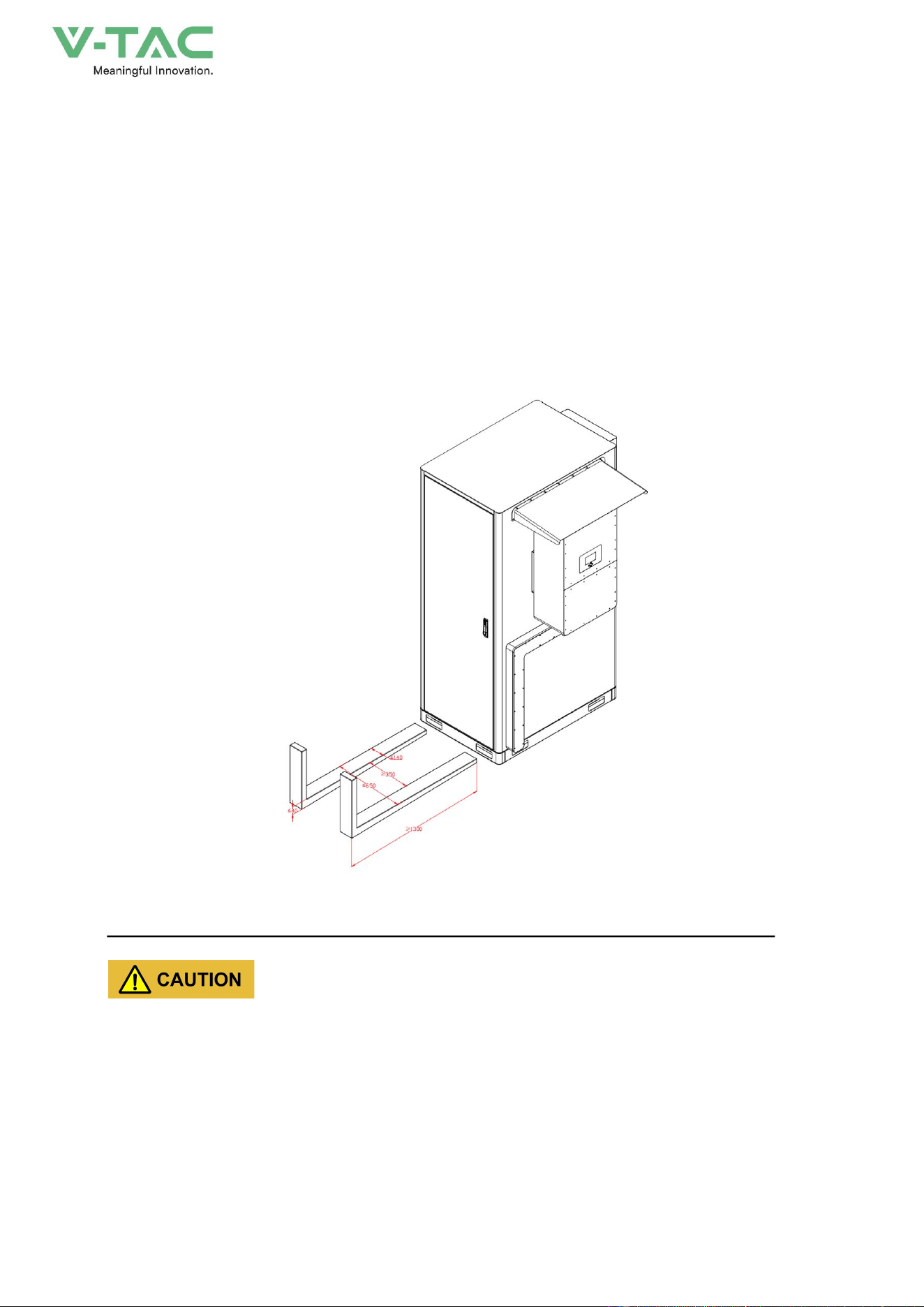
3.4.1 Forklift Transportation
This device can be carried by forklift. When you move the energy storage system by forklift, the
forklift arm must be inserted from the front of the device and completely pass through the bottom of the
device, as shown in Figure3-6.
Figure3-6 Forklift transportation diagram (unit: mm)
* Forklift should have a safety factor of at least 2 times weight of the energy storage system.
* When lifting the energy storage system, keep the centre of gravity of the energy storage system
at the center of the two forks and keep the handling process slow and smooth.
* Pay attention to the width and inserted depth between the fork arms to prevent instability or
tipping.
* Pay attention to the distance between the forklift and the device to avoid damage to the
appearance, door locks and louvers.
31
* During moving, the tilt angle of the energy storage system should not exceed 10°, do not put it
down or lift it up suddenly, and pay attention to the turning, up ramps and down ramps to avoid
collision of the device.
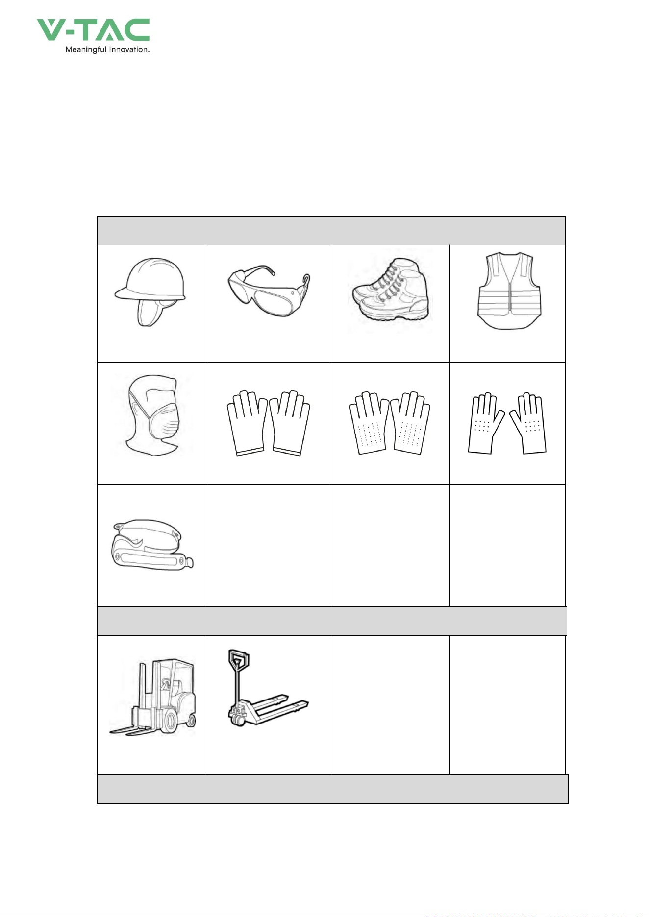
3.5 Installation Preparation
3.5.1 Tools
Personal protection
Safety helmet
Protective glasses
Insulated shoes
Reflective jacket
Dust mask
Protective gloves
ESD gloves
Insulated gloves
Safety belt
Transportation tools
Forklift
Manual forklift
Installation tools
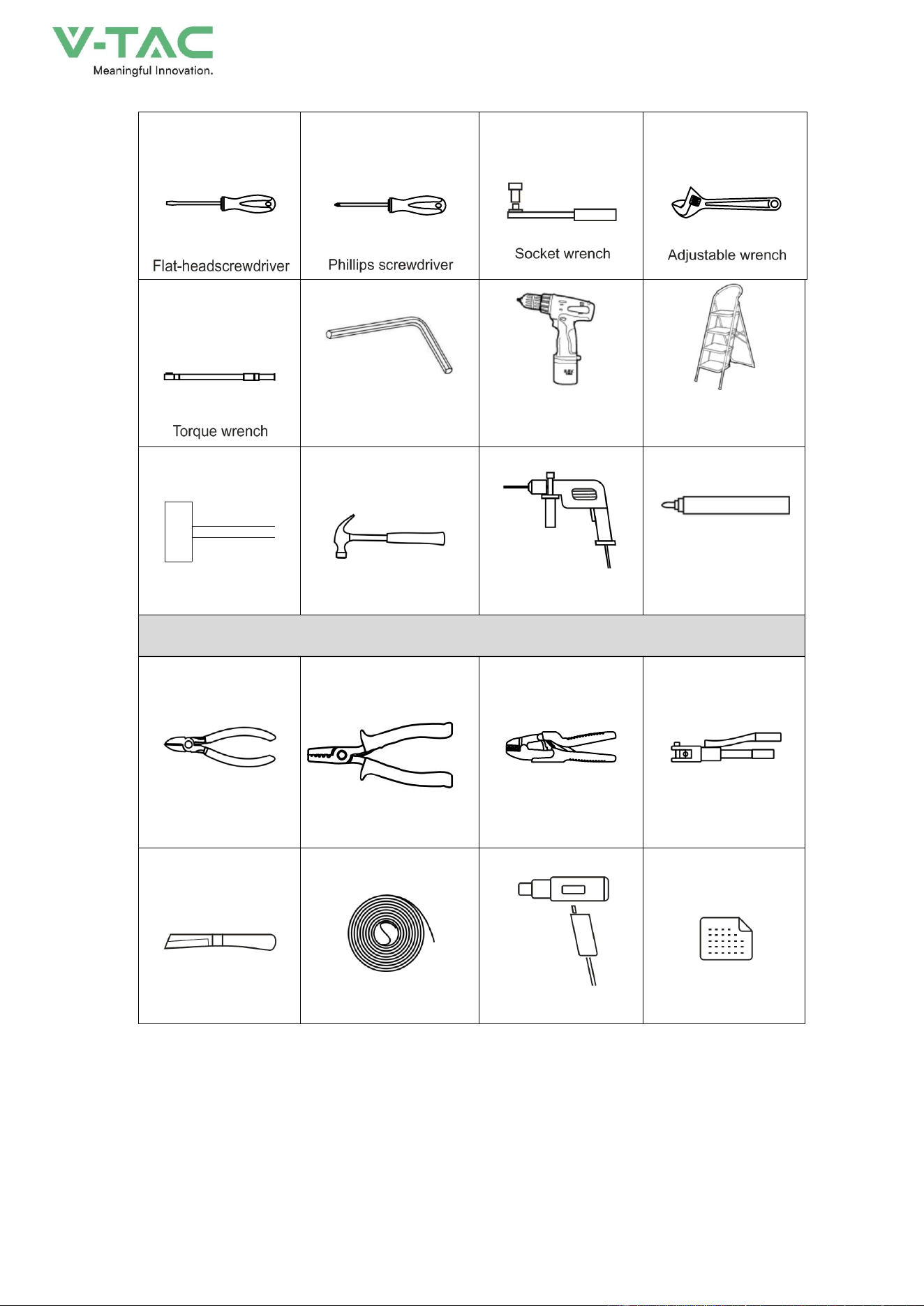
32
Wrench
Electric screwdriver
Ladder
Rubber hammer
claw hammer
Hammer dril
Mark pen
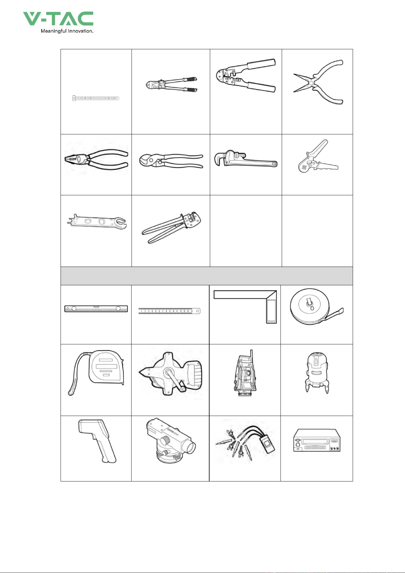
Wiring tools
Diagonal pliers
wire stripper
COAx crimping tool
Hydraulic pliers
Electrician's knife
Heat shrink tubing
Heat gun
Label paper
33
cable tie
Cutting plier
Network cable
crimping plier
Needle-nose plier
Plier
Wire cutter
Tube plier
Crimping plier
Open-ended wrench
Crimping plier
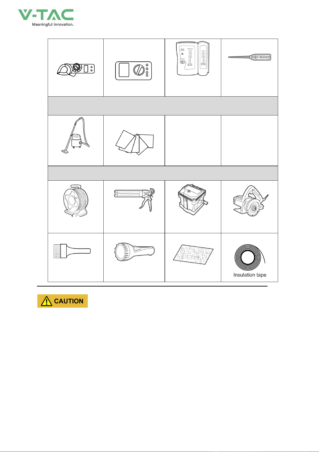
Measurement tool
Levelling instrument
Steel ruler
Rectangular ruler
Long tap measure
Tap measure
Long coiled steel ruler
Altimeter
Laser locator
Thermometer
Level
Phase sequence meter
Pressure tester
34
clamp meter
Network cable tester
Ammeter
1. Cleaning tools
Vacuum cleaner
cotton cloth
Others
Cable coil reel
Sealant, sealant gun
Insulation
resistance meter
Small cutter
Flashlight
Flashlight
Sand paper
The installation tools need to be insulated to avoid electric shock.
3.5.2 Size
35
3.6 Mechanical Installation
The energy storage system can be installed on the foundation according to the actual condition on
site.
The energy storage system can only be installed without damage or fault.
* Only trained professionals are allowed to install the energy storage system. Improper installation
may result in injury.
* Wear suitable protective equipment for personal protection in case of accidents during
operating.
3.6.1 Foundation Installation
If the foundation installation is used, the foundation must be built according to the requirements for
bottom installation holes and wiring holes of the energy storage system.
The energy storage system is heavy (<1.5t). Before building the foundation, the installation site
conditions (mainly geological conditions and environmental climate conditions, etc.) should be
investigated in detail. And then the design and construction of the foundation can be performed.
36
Foundation Requirements
Unreasonable foundation construction will bring great difficulties or troubles to the placement,
opening and closing of the energy storage system and later operation, therefore, the foundation of the
energy storage system must be designed and constructed in accordance with certain standards in
advance to meet the requirements of mechanical support, cable routing, and later maintenance.
The foundation should be constructed according to the following requirements at least:
* The foundation must ensure the stability and safety of the installation of the energy storage
system.
− The foundation must have sufficient bearing capacity to effectively support the energy storage
system.
− The soil at the installation site needs to be compact. If the soil is loose, take measures to
ensure that the foundation is stable.
− The bottom foundation pit must be tamped and filled up.
− The upper surface of the foundation must be at the same level (no more than 5 mm).
* The foundation should be higher than the natural floor to avoid erosion of the bottom and interior
of the energy storage system after rain or snowmelt water.
* Construct corresponding drainage measures according to local geological conditions.
* Build a cement foundation with sufficient cross-sectional area and height. The height of the
foundation is to be determined by the construction party according to the geology on site.
The excavated soil during the foundation construction should be cleared in time to avoid affecting the
subsequent forklift operation of the energy storage system..
When designing the direction of the air outlet, the wind direction of the installation site should be
considered.
Grounding System Requirements
When constructing the foundation, the grounding flat steel should be reserved, and the grounding
with the energy storage system needs to be bolted firmly.
The grounding system should be constructed by the user according to the geological conditions of
the installation place and relevant regulations. No matter what kind of grounding method, the
grounding resistance should be no more than 0.1Ω .
37
4.Electrical Connection
4.1 Installation Process
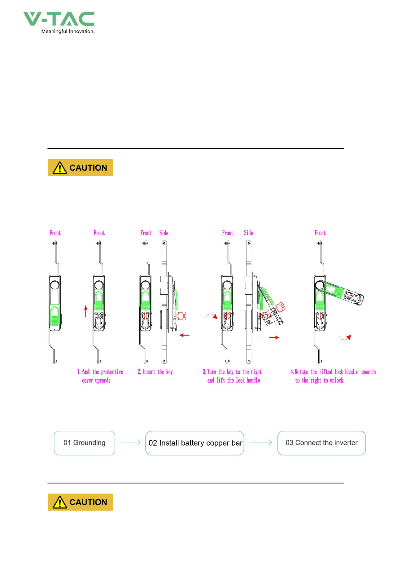
4.1.1 push plate
The user needs to open the cabinet door of the energy storage system before wiring. The opening
and closing of the cabinet door both require the use of a cabinet door key. The opening steps are
illustrated in the following figure:
*Please use the key provided with the machine to open the cabinet door. To close the door,
please perform the reverse operation.
*Please keep the key properly after use.
4.1.2Electrical connection sequence
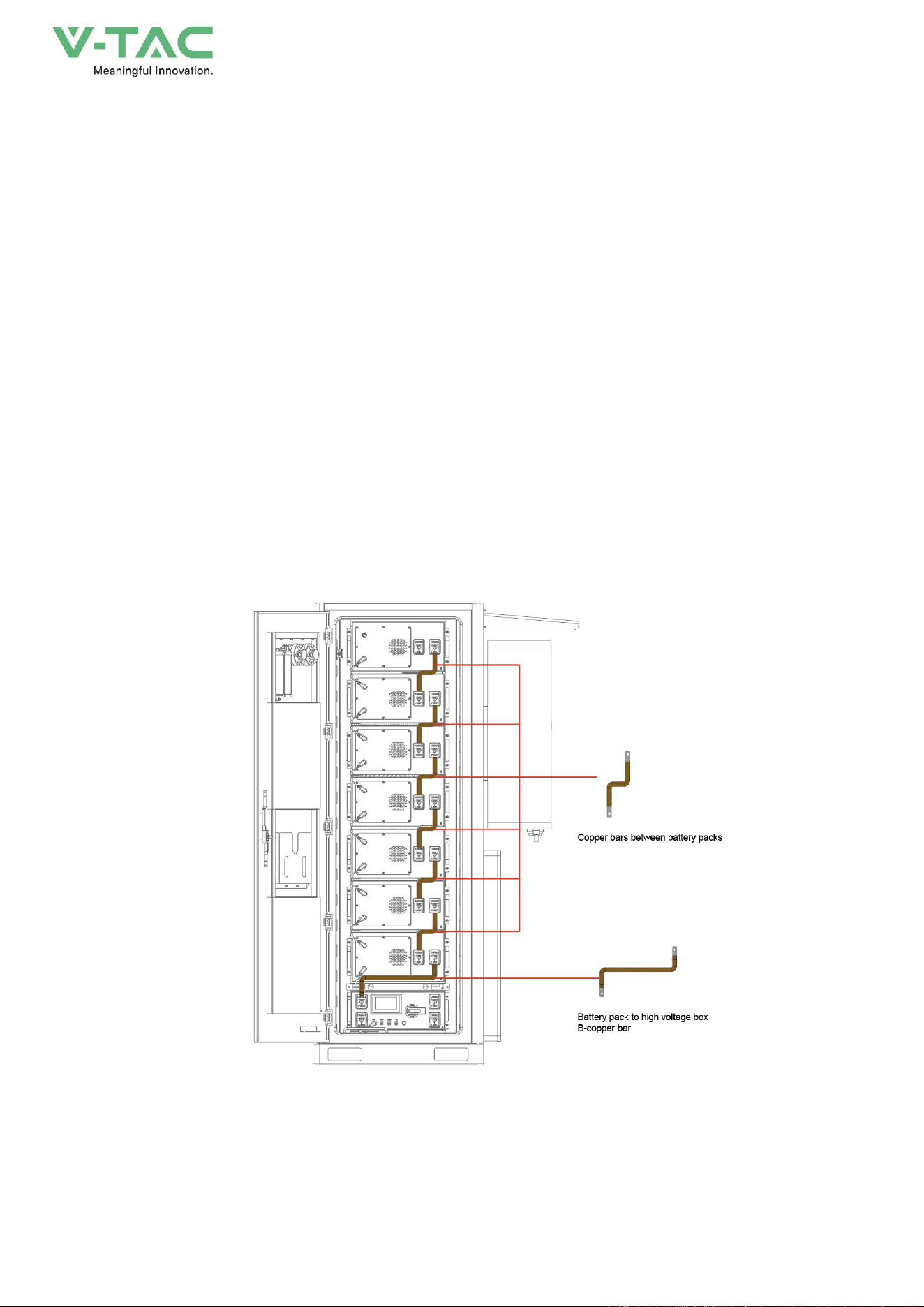
4.1.3Installation of battery pack copper bar
* The cable connections between the batteries inside the energy storage system have been
38
completed. The connections shown in the figure are for illustration only.
* The bronze medal on the energy storage system pack is in an uninstalled state to ensure safe
transportation
Step 1
Take out the copper bars from the accessory box, check the quantity and appearance. Connect 6
battery packs to the battery pack copper bars and 1 battery pack to the high-voltage box B-copper bar.
Rotate the circuit breaker handle of the high-voltage box to the off direction
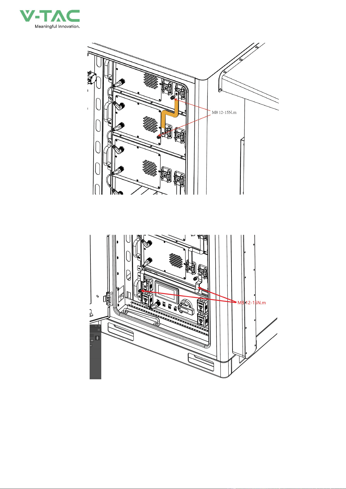
Step 2
As shown in Figures 4-1 and 4-2, use a Phillips screwdriver to install the copper bars from top to
bottom, with screw M8 and torque of 12-15N. m
Step 3
As shown in Figure 4-3, use a cross screwdriver to fix the copper bar on the negative terminal of
the battery pack and the terminal of high voltage box B -, install screw M8, torque 12-15N
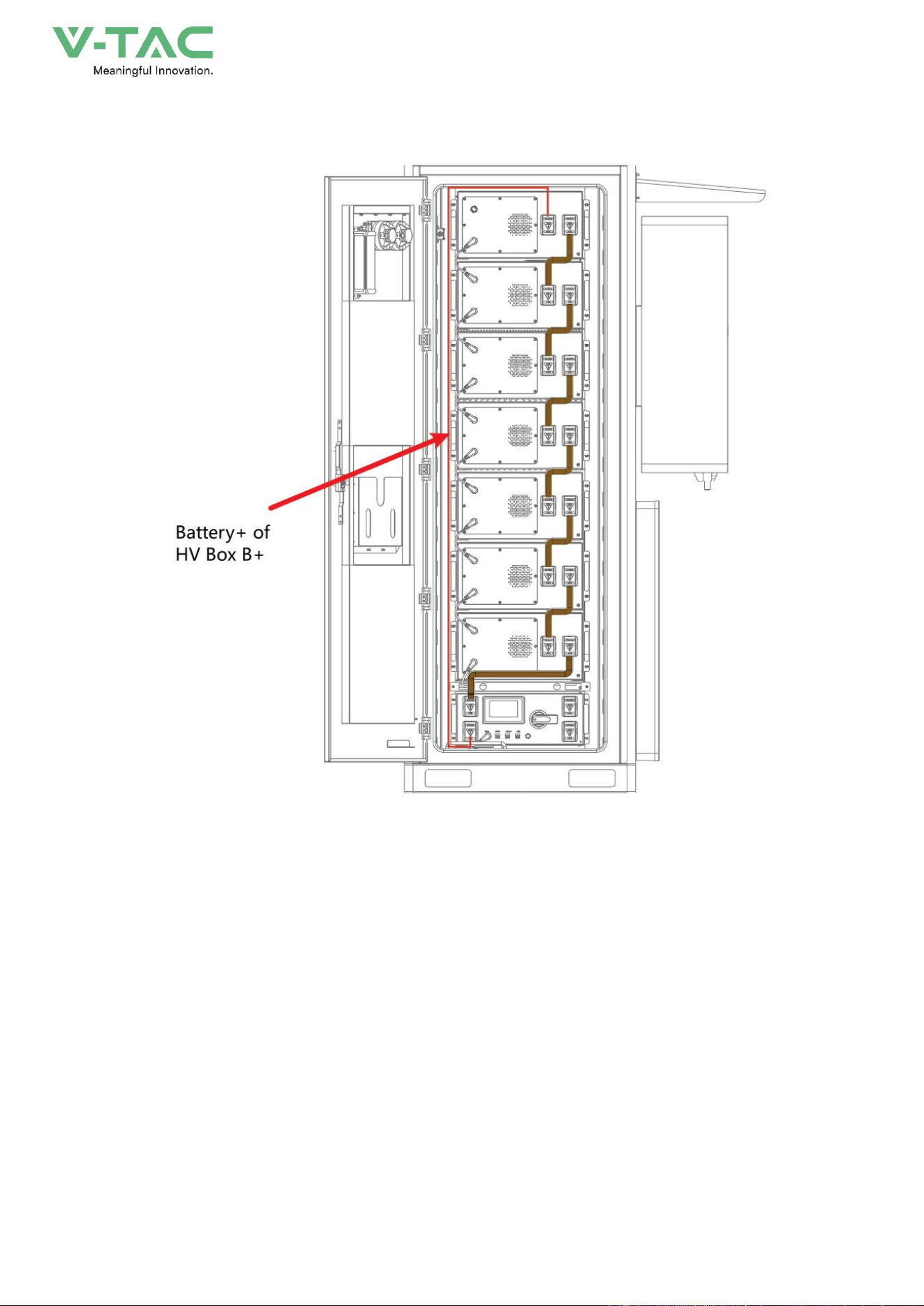
Step 4
As shown in Figure 4-4, use a Phillips screwdriver to fix the connecting wire to the positive
terminal of the topmost battery pack and the B+terminal of the high-voltage box. Install screw M8 with
a torque of 12-15N
Figure4-1 Diagram of Copper Bar Installation
39
Figure4-2 Diagram of Copper Bar Installation
Figure4-3 Diagram of Copper Bar Installation
40
Figure4-4Diagram of Copper Bar Installation
4.2 Wiring
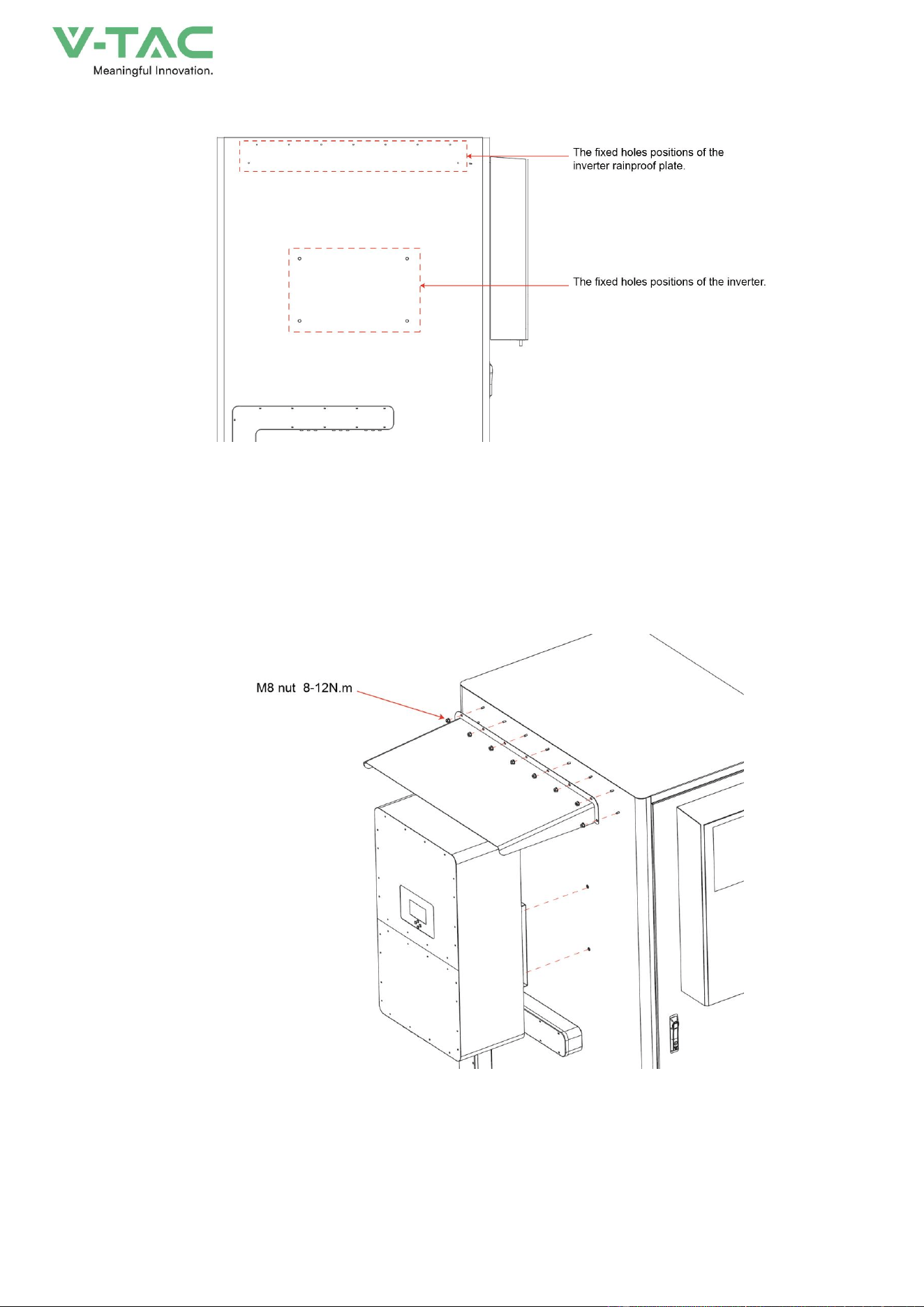
Step 1
Remove the inverter from the packaging and fix it on the side of the cabinet. The specific
installation position is shown in the inverter fixing holes in Figure 4-5. Attention: The inverter is heavy,
please install it carefully and do not bump it. Please refer to the installation manual of the inverter
brand for installation details.
41
Figure4-5 Installation hole description
Step 2
Complete step 1, install the waterproof cover on the inverter, and fix the waterproof cover on the
cabinet with M6 nuts, refer to Figure 4-6 below
Figure4-6 installation diagram
42
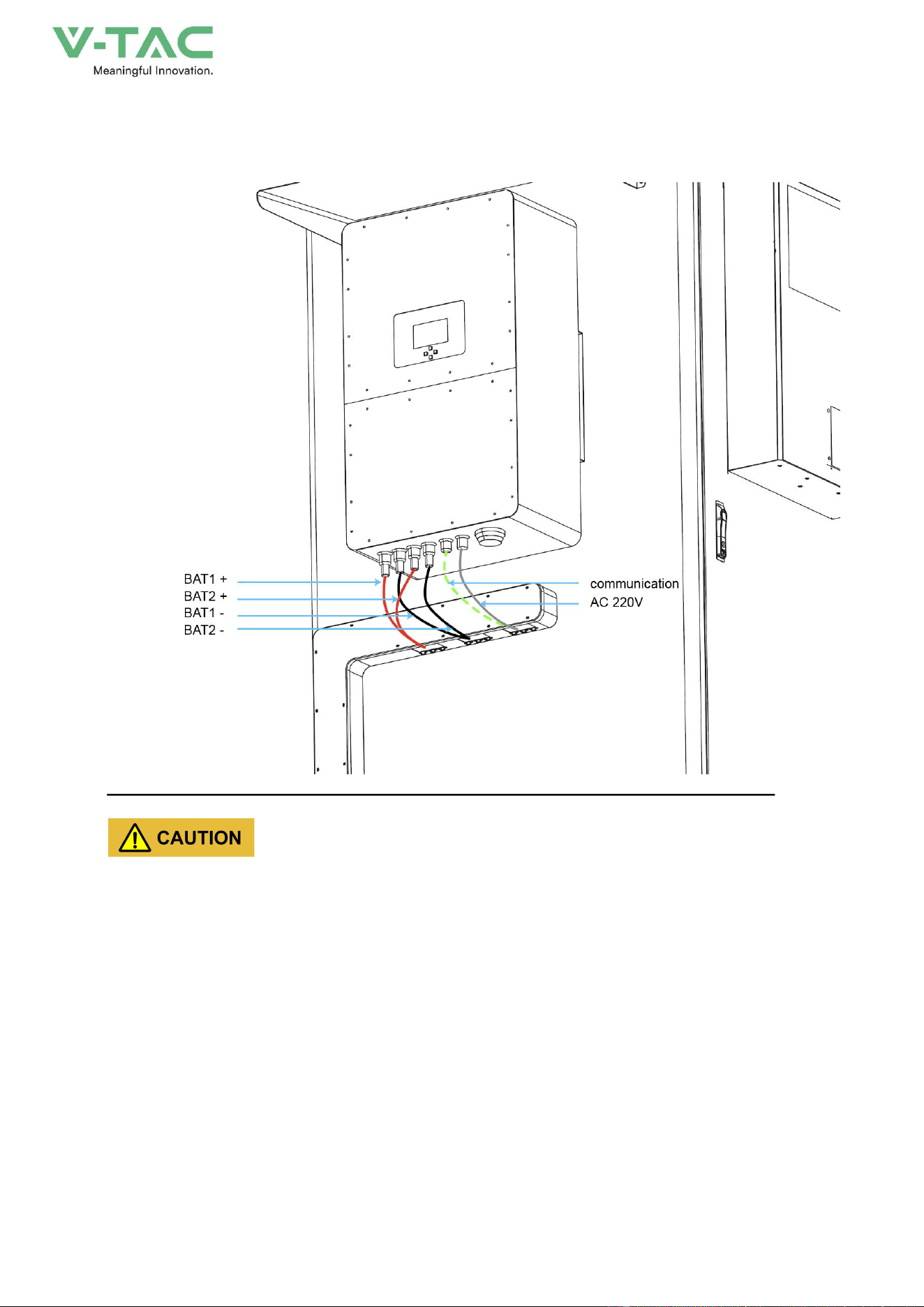
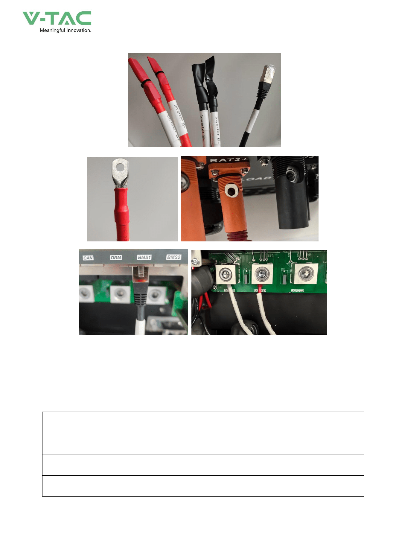
Step 3:Open the cable tray on the side panel of the cabinet and remove the connecting wires. Connect
BAT1+, BAT1-, BAT2+, BAT2-, BMS1 and PCS220V respectively.
* Before wiring, it is necessary to confirm that the control box of the high-voltage box and the DC
switch are all in the disconnected state.
* Safety precautions need to be taken.
* The wiring installation must comply with the specifications of the inverter.
* After the wiring is completed, install the wire trough cover plate. It is recommended to fill the wire
outlet holes with fireproof mud.
43
Step 4:Complete the wiring and conduct the inspection..
After the entire installation of the energy storage system is completed, a comprehensive inspection
of its mechanical installation and electrical connections should be carried out. At least two staff
members should conduct the inspection according to the items listed in the table below. Records
should be kept during the inspection. If any items that do not meet national, industry, and regulatory
requirements are found, they should be corrected immediately.
Mechanical installation inspection
The energy storage system is not deformed or damaged
The bottom of the energy storage system is fixed and the support is stable and reliable
There is plenty of space around the energy storage system

44
The temperature, humidity and ventilation conditions of the environment where the energy storage
system is located meet the requirements
The cooling air circulates smoothly
The cabinet body has complete and reliable sealing protection
Electrical installation inspection
The grounding of the energy storage system is complete and firm
The positive and negative poles of the DC input are connected correctly, and the tightening torque
meets the requirements
The communication wiring is correct and should be kept at a certain distance from other cables
The cable wire numbers are marked correctly, clearly and easily distinguishable
The insulating protective cover is complete and reliable, and the danger warning label is clear and
firm
Other examinations
All the vacant cables are fastened tightly with insulating cable ties
There are no remaining tools, parts, conductive dust or other foreign objects from drilling inside the
cabinet
There is no condensed moisture or ice inside the cabinet

45
5.System debugging
5.1 Startup check
Before operating, check and make sure that there is no damage on the energy storage system or exist
other potential hazards.
Number
Check items
1
The equipment is installed firmly, the installation position is convenient for operation and
maintenance, the installation space is convenient for ventilation and heat dissipation, and
the installation environment is clean and tidy.
2
The protective earth wire, grid-connected AC line, load line and communication line are
correctly and firmly connected.
3
The cable binding meets the wiring requirements, is distributed reasonably and has no
damage.
4
The battery cluster switch, AC switch and DC power supply switch have been
disconnected.
5
The voltage and frequency of the grid-connected access point of the energy storage
system shall meet the grid connection requirements of the country/region where it is
located.
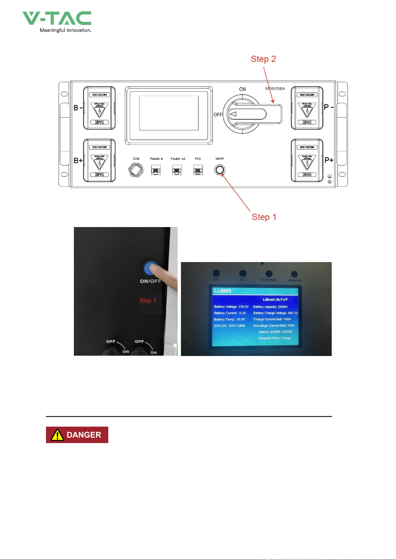
5.2 The system is turned on
Step 1:Press the ON/OFF circular button of the high-voltage control box. When you hear the
sound of the relay engaging, check whether the display interface is a fault alarm.
Step 2:Rotate the selection handle ON the high-voltage control box to ON.
Step 3:Turn on the inverter and check the operating data.
46
5.3 The system shuts down
* When operating and maintaining the energy storage system, please power off the system. Operating
the equipment with power on May cause damage to the energy storage system or pose an electric
shock hazard.
* After the energy storage system is powered off, it will take some time for the internal components to
discharge. Please wait until the device is completely discharged according to the required time label.

47
Step 1:Confirm that all the loads have been turned off. Open the backdoor and turn off all the
switches.
Step 2:Turn off the inverter.
Step 3:Select the handle on the high-voltage control box to OFF, press the circular switch, and
hear the sound of the relay disconnecting.
Step 4:Disassemble the copper bars between batteries.
48
6.OHA’S User Interface
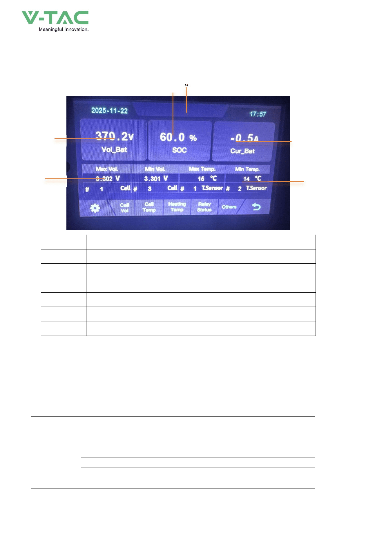
6.1 Main Interface
2
NO.
Description
Function
1
SOC
Display real-time SOC value of energy storage system
2
Voltage
Display real-time voltage
3
Temperature
Displays the maximum and minimum battery temperatures
4
Voltage
Displays real-time maximum and minimum cell voltages
5
Current
Display battery real-time current
6
System status
Display battery fault name (For details, see Table 5-2)
6.2Alarm description and processing
When protection mode is activated or system failure occurred, the alarm signal will be given
through the system status on the LCD. The network management can query the specific alarm categories.
If the fault such as single cell over voltage, charging over-current, under-voltage protection,
high-temp protection and other abnormalities which affects the output, please deal with it
according to Table 5-2.
Table 5-2 Main alarm and Protection
Statue
Alarm category
system status
Processing
Charge state
Over-current
Over-current during slow charging
Stop charging and find
out the cause of the
trouble
Over-voltage
Cell voltage too high in charge
Stop charging
High temp
Temperature too high in charge
Stop charging
Low temp
Temperature too low in charge
Stop charging
1 6
3
5
4
49
Discharge state
Over-current
Continuous over-current
Stop discharging
Low-voltage
Cell voltage too low in discharge
Stop discharging
High temp
Temperature too high in discharge
Stop discharging
Low temp
Temperature too low in discharge
Stop discharging
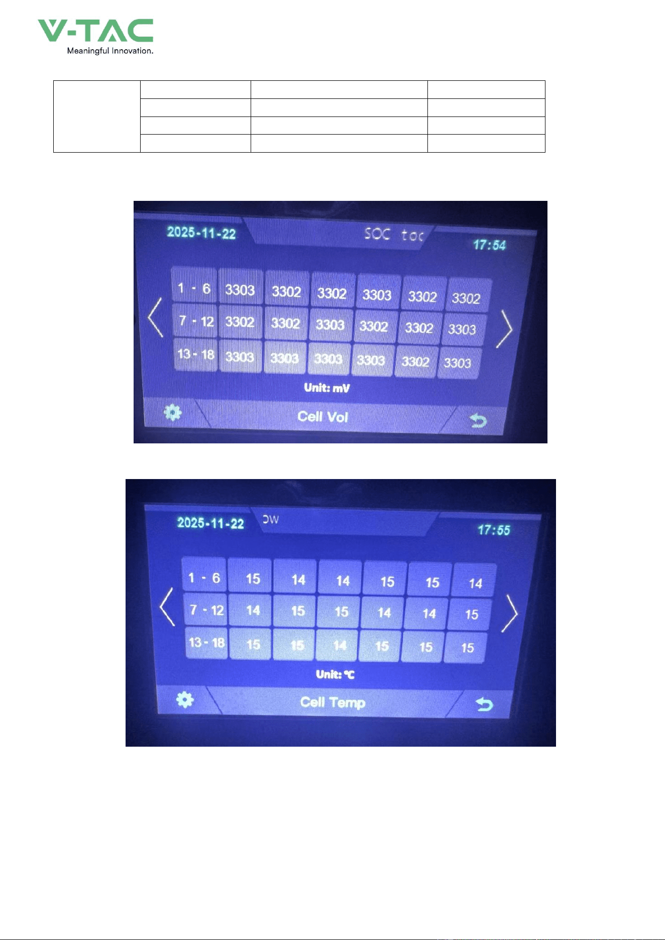
6.3 Cell Voltage
6.4 Cell Temperature
50
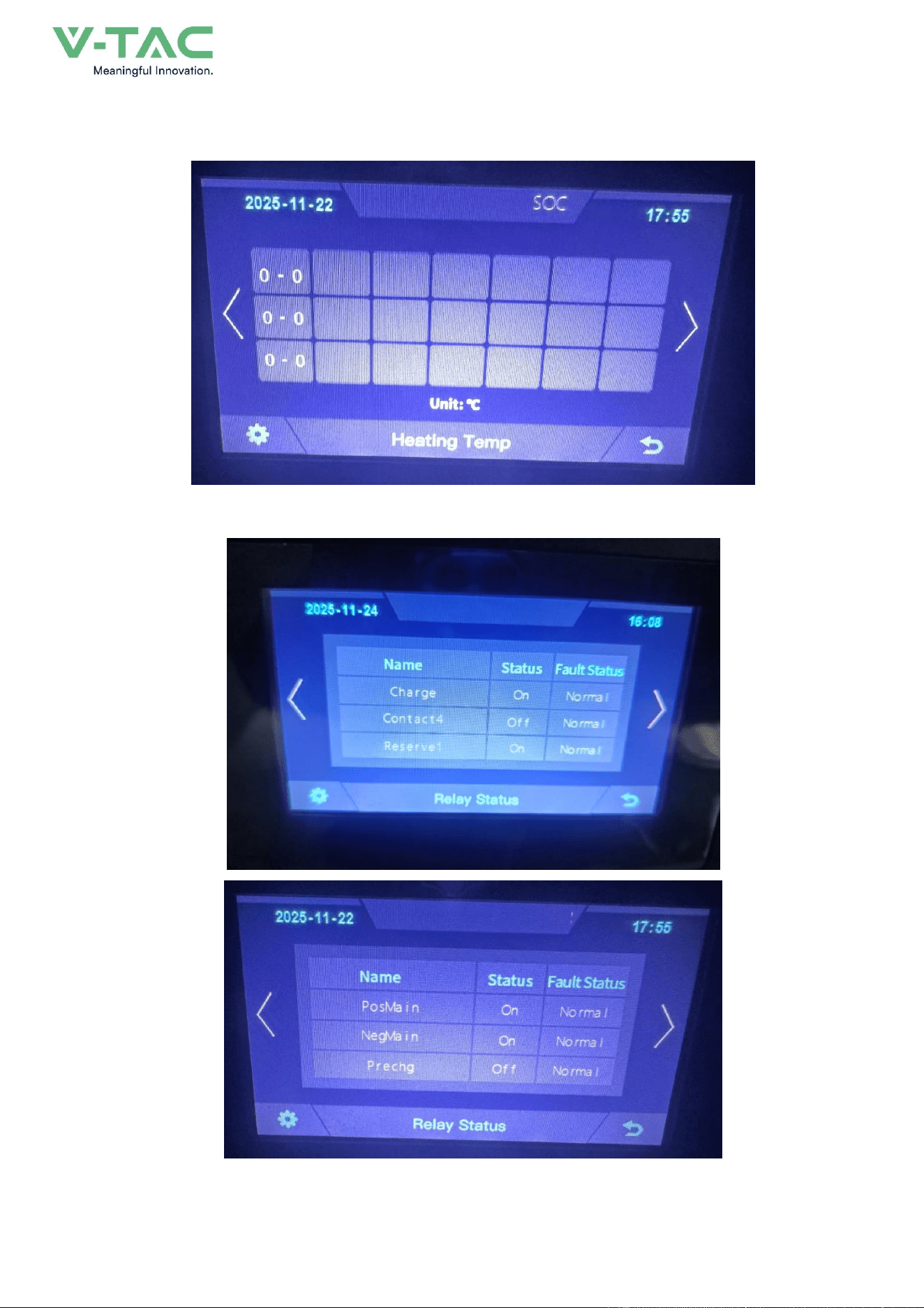
6.5 Heating Temperature
6.6 Relay Status
51
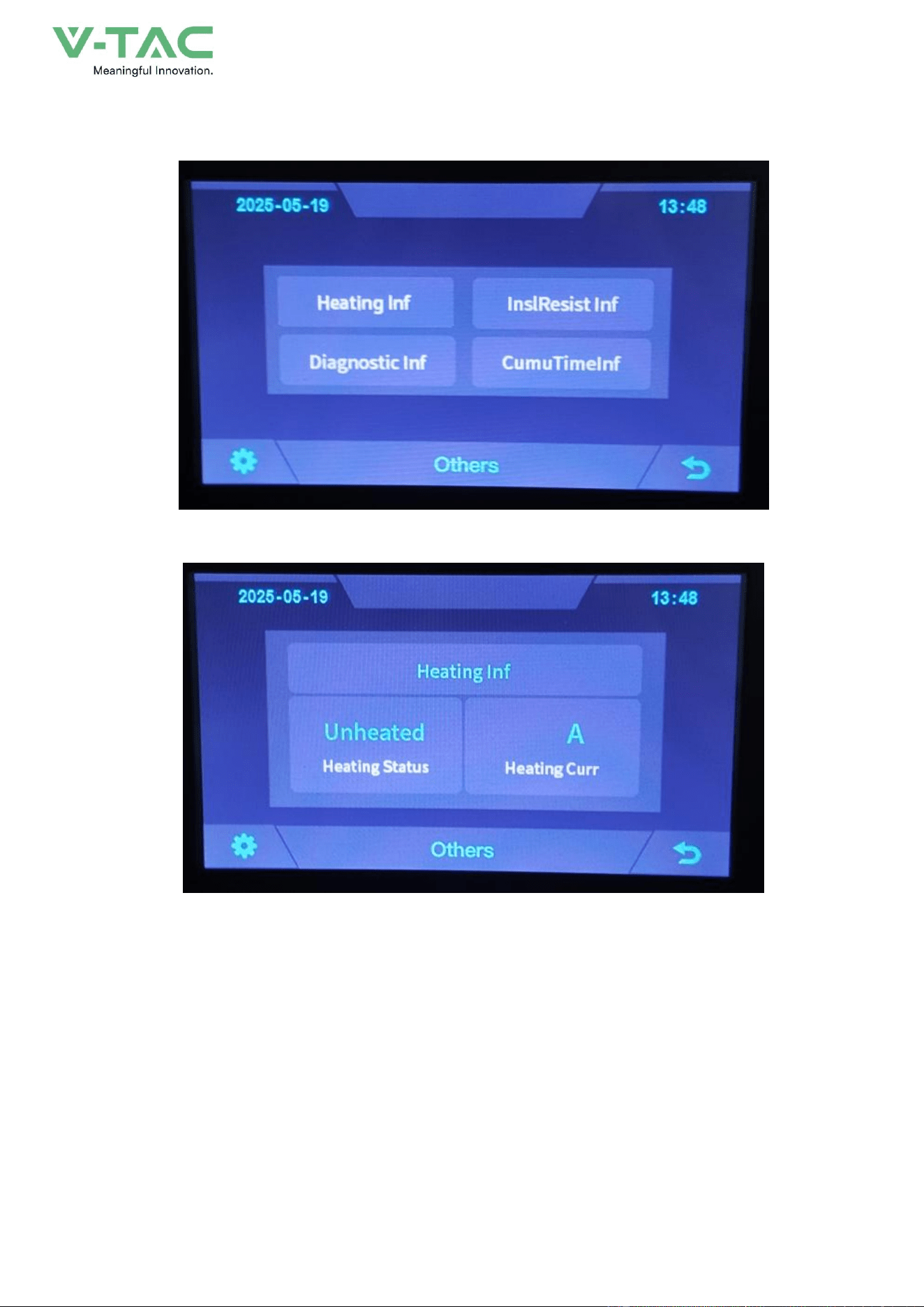
6.7 Other
6.7.1 Heating Information
52
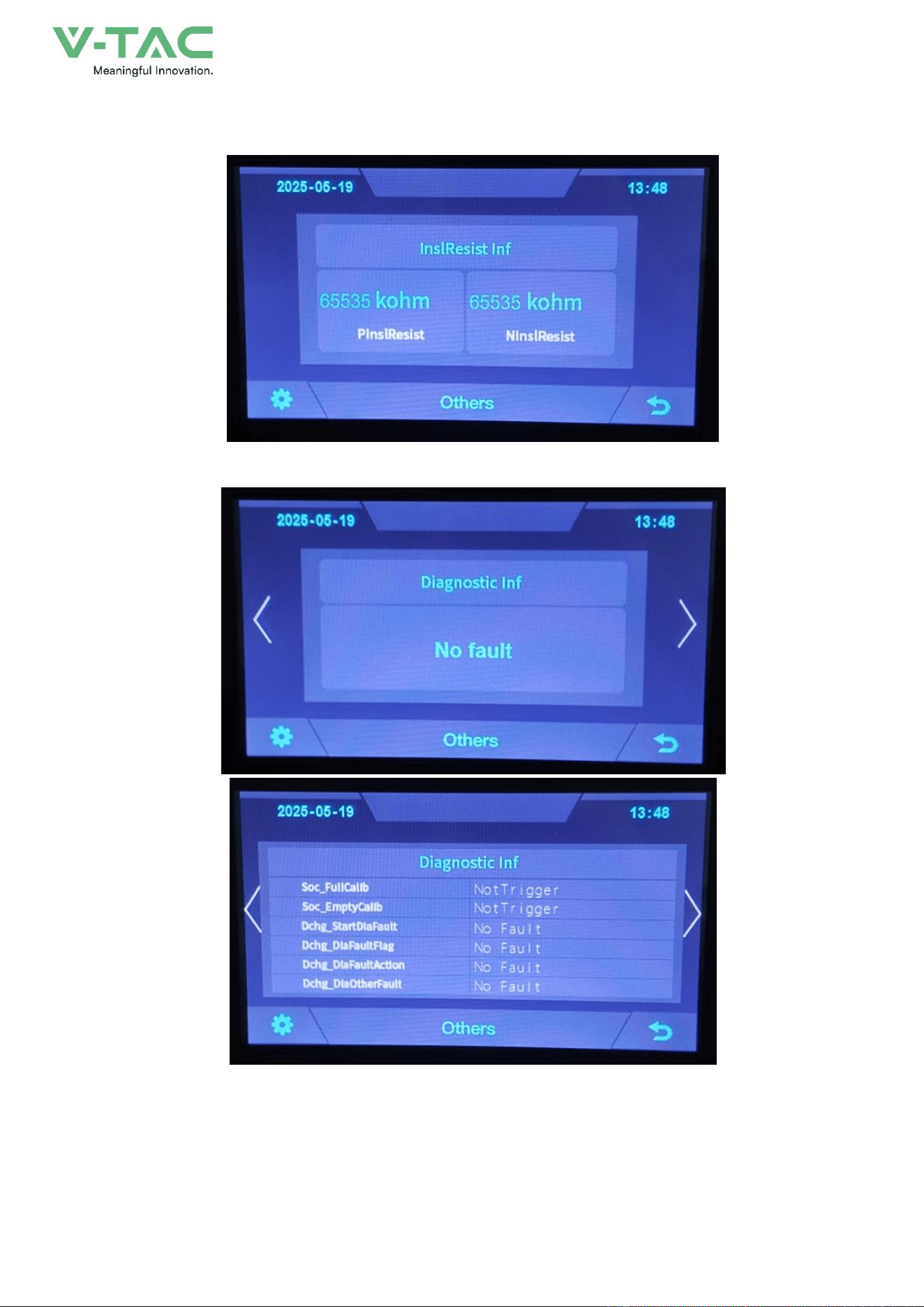
6.7.2 Insulation Resistense
6.7.3 Diagnostic Information
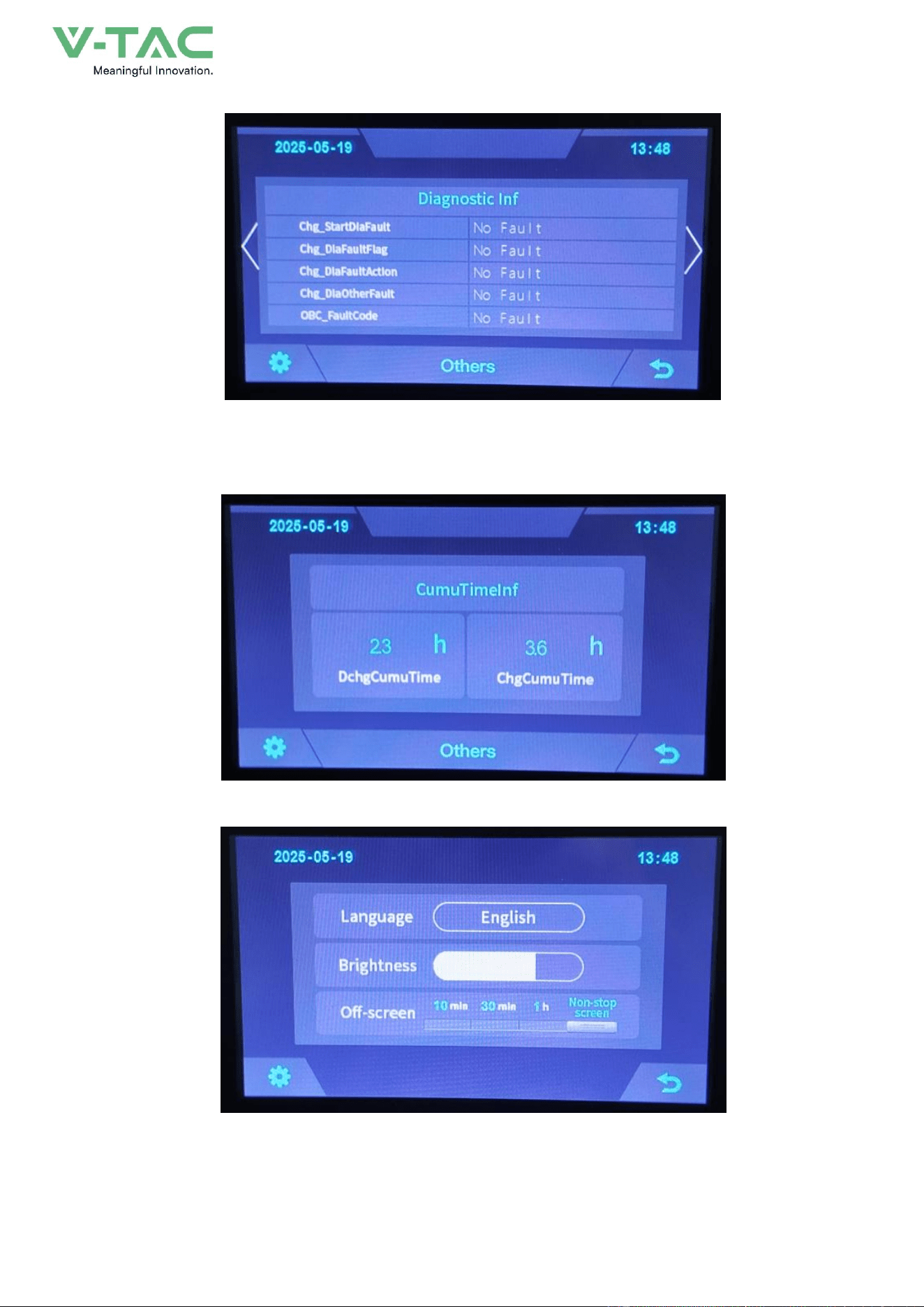
53
6.7.4 Cumulative Time Information
6.8 Set Up
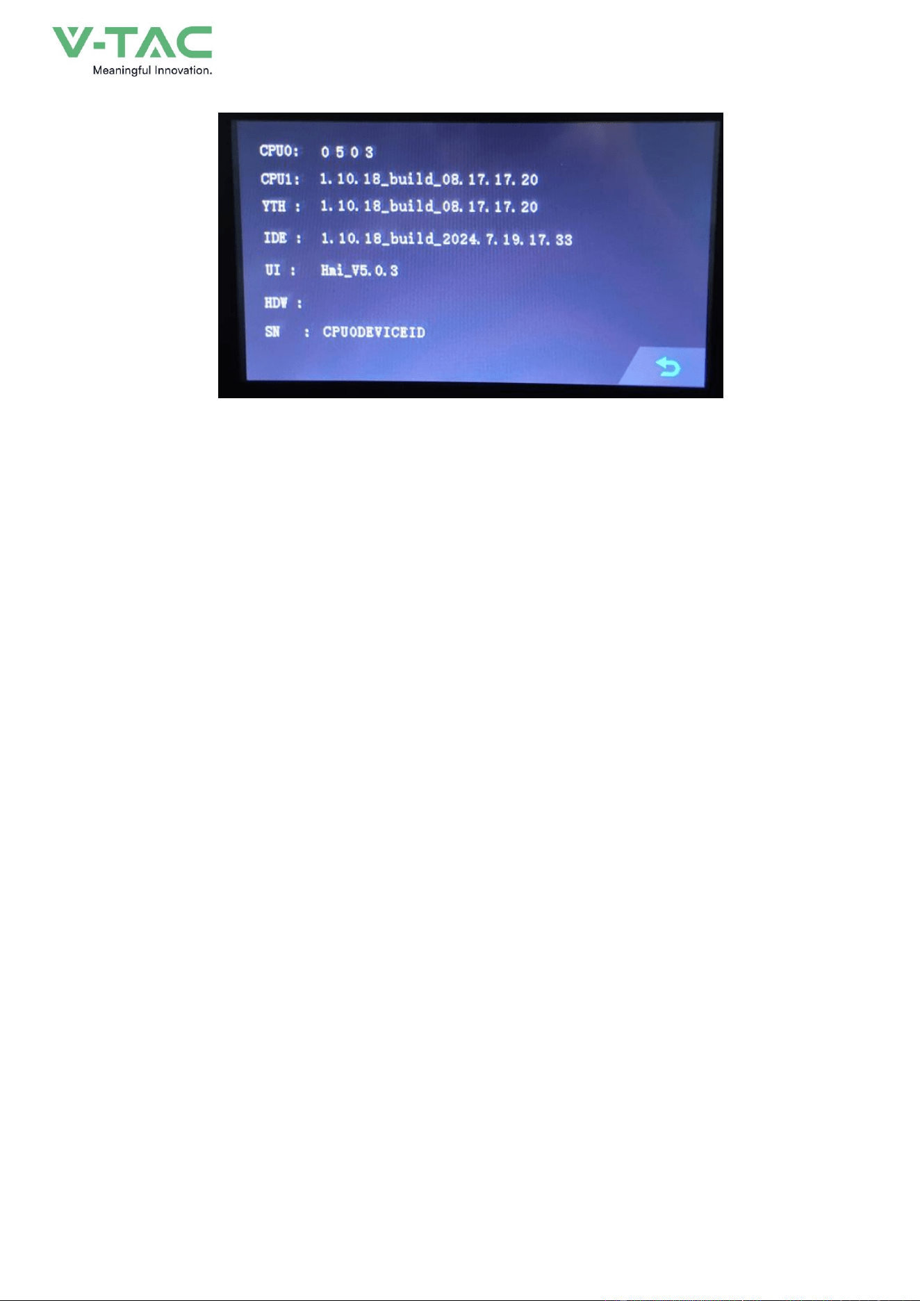
54

55
7. Xiaodan Energy Storage App
7.1 App download
7.1.1 Android version
1.
Enter the official website of Youdan Technology https://www.udantech.com/#/ , click on the
"SAAS Application" column in the top navigation bar, pull down to the mobile app application
module, and you can see the mobile WeChat Mini Program and App application download.

56
7.1.2 iOS version
Enter the mobile App Store, search for "Xiaodan Energy Storage", and you can download and
install it.
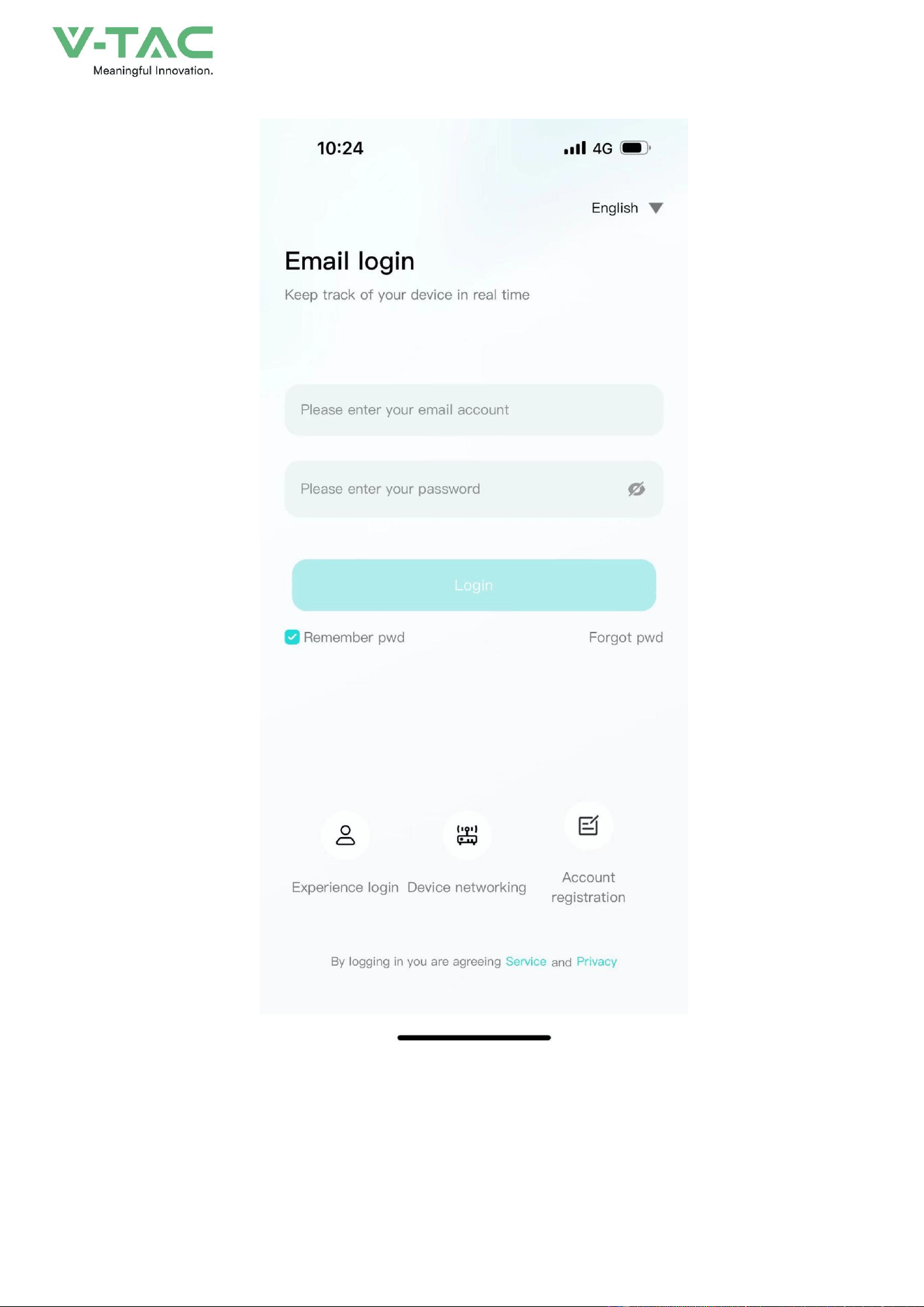
7.2. Log in and register
7.2.1 Log in
• After opening the APP, enter the login interface to log in with your account.
•
Currently supports logging in through email accounts
57
7.2.2 Register
• At the bottom of the login page, click the "Account Registration" button to enter the
registration process.
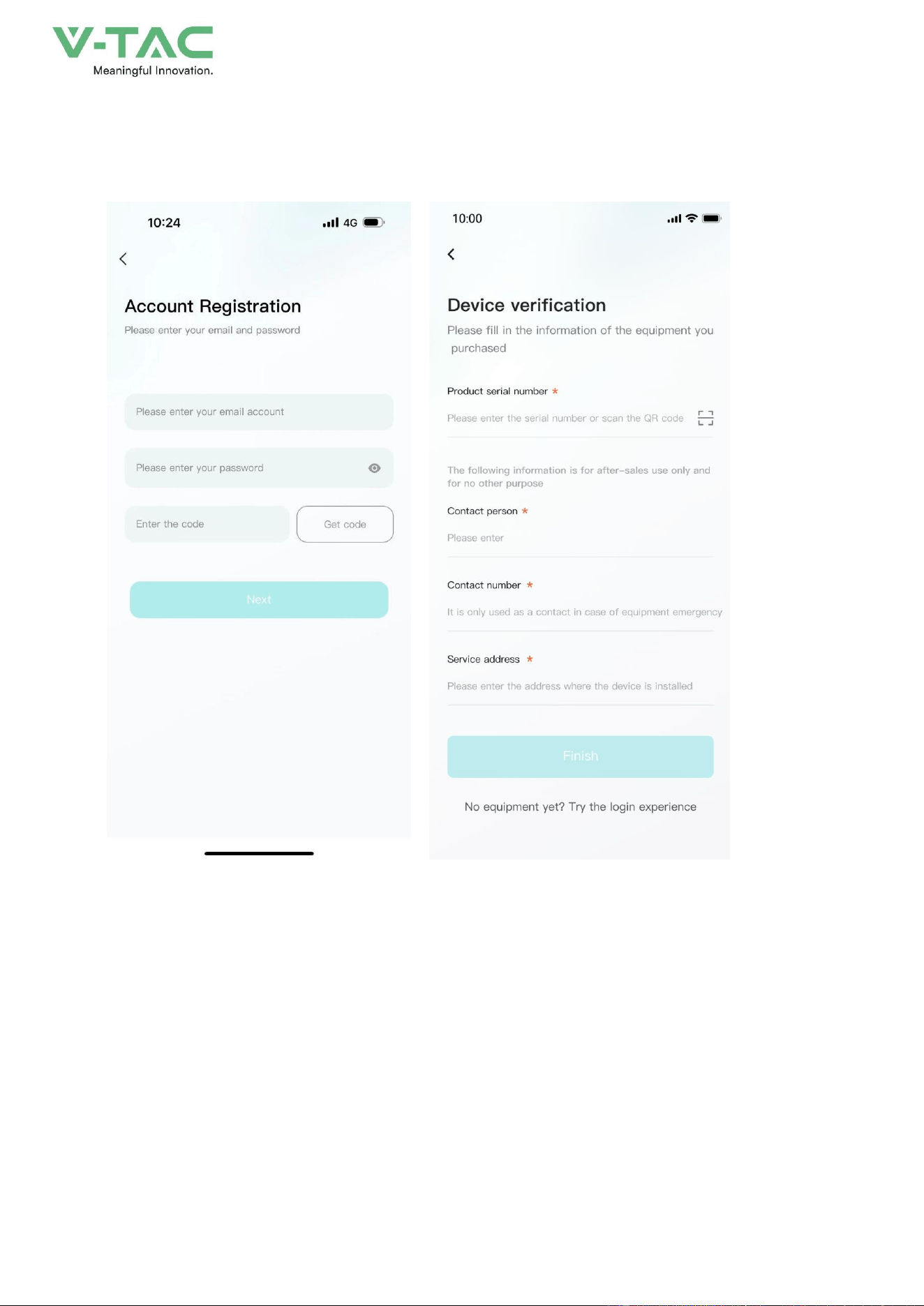
58
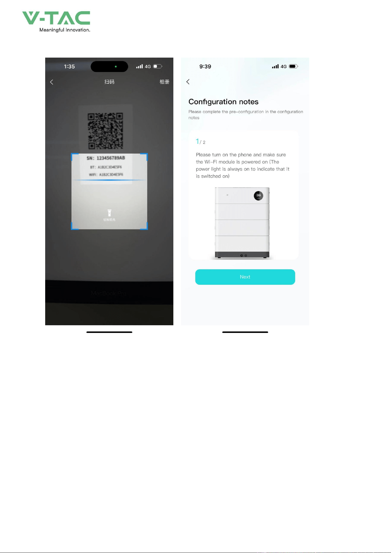
• Currently, you can register with an email account. After registration, you need to go through
the device verification process and enter the device SN code or device QR code for identification.
7.2.3 Experience login
•
At the bottom of the login page, click the "Experience Login" button to experience the app
function without registration as a tourist.

59
7.3. Equipment distribution network
The system adopts a 4G module and there is no need to reconfigure the network.
7.4. App page
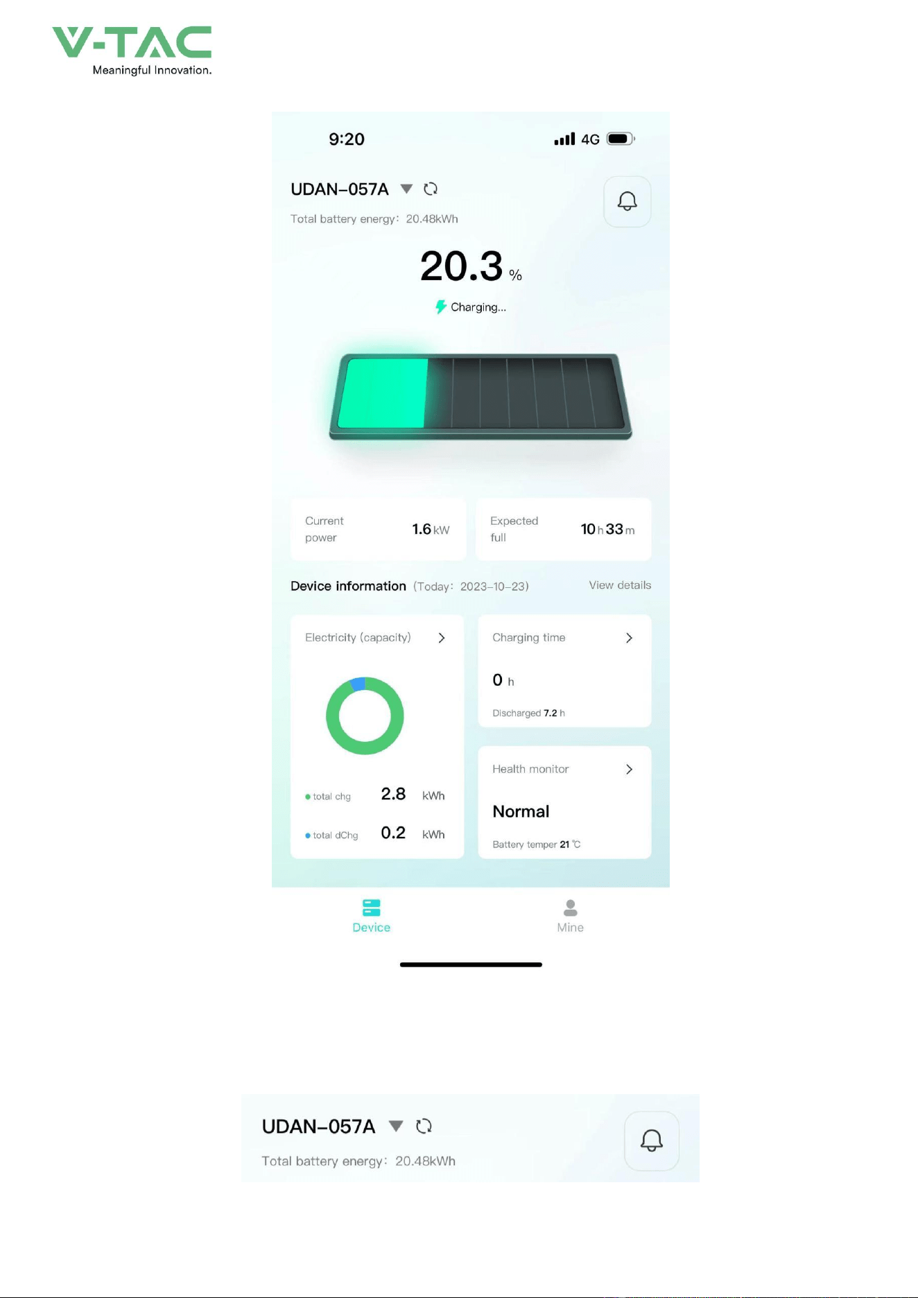
7.4.1 Equipment
The device homepage is used to display the currently managed device information.
60
•
The top area displays the device name, battery energy, and message entry.
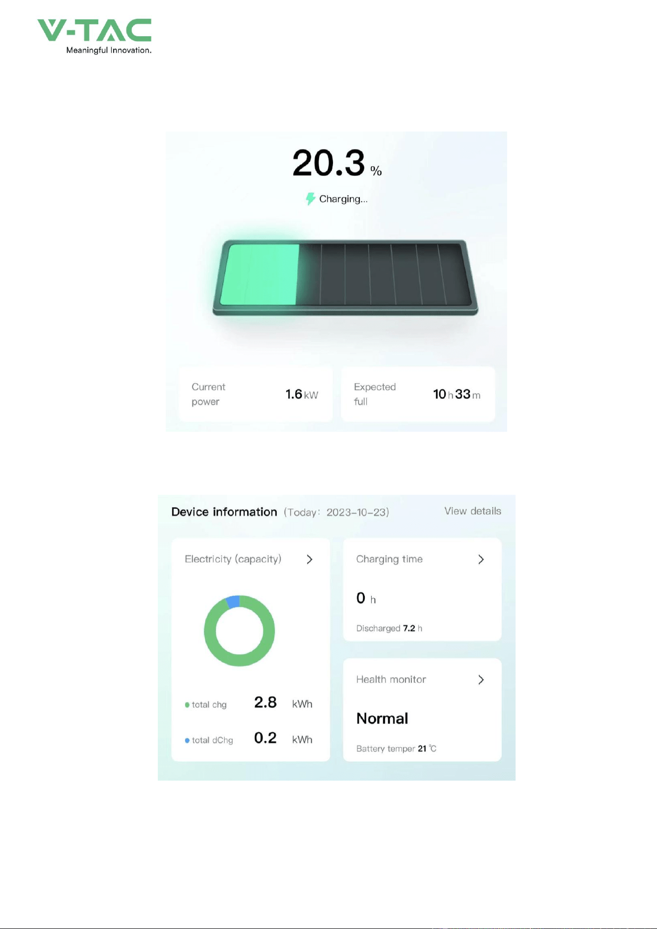
61
• Middle area: Displays the current battery charging and discharging status, battery percentage,
current power, and estimated full time.
•
The bottom area: Displays the device battery, charging time, and health check overview data
of the day in the form of a card. You can click the corresponding card to view the details.
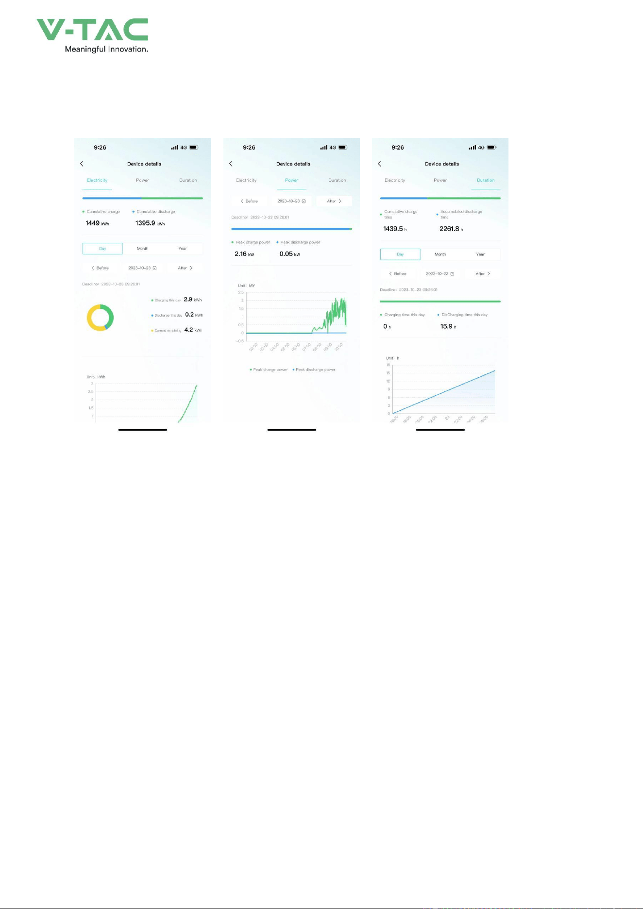
7.4.2 Data details
62
Display the data details of the current device, and view the battery, charging and discharging
power, and charging and discharging time data separately, and support time filtering.
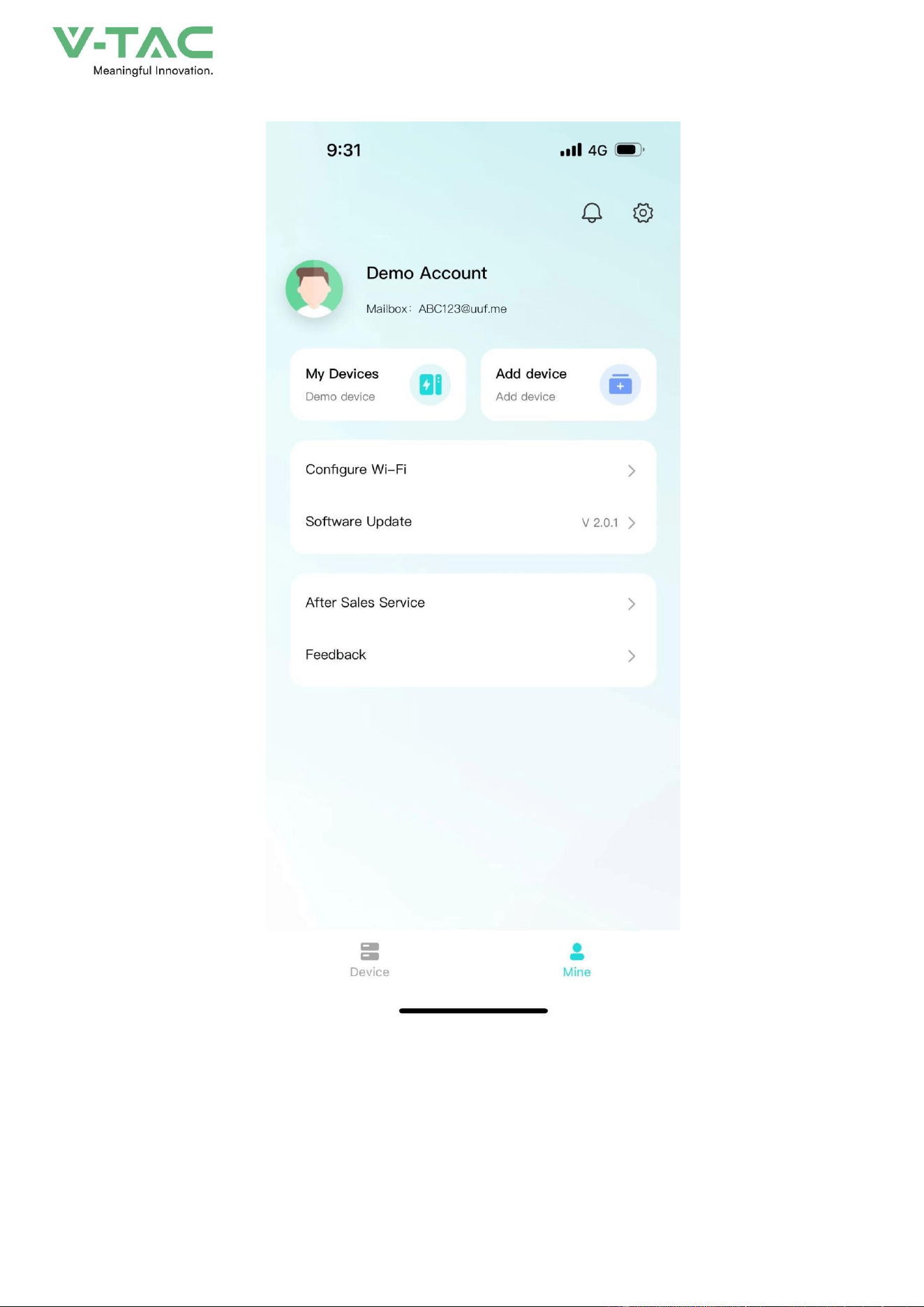
7.4.3 Mine
My page allows users to view my devices, add devices, configure WiFi, software updates,
after-sales services, problem feedback, app settings .
63
• Click "My Devices" to enter Facility Management. You can view all devices managed under
the current account, switch devices displayed on the homepage, unbind devices, and other
operations.

64
• Click "Add Device" to enter the code scanning page.
•
Click "Equipment Distribution Network" to enter the equipment distribution network process.
65
• After clicking "software update", it will enter the version detection. If there is a new version, it
will be updated.
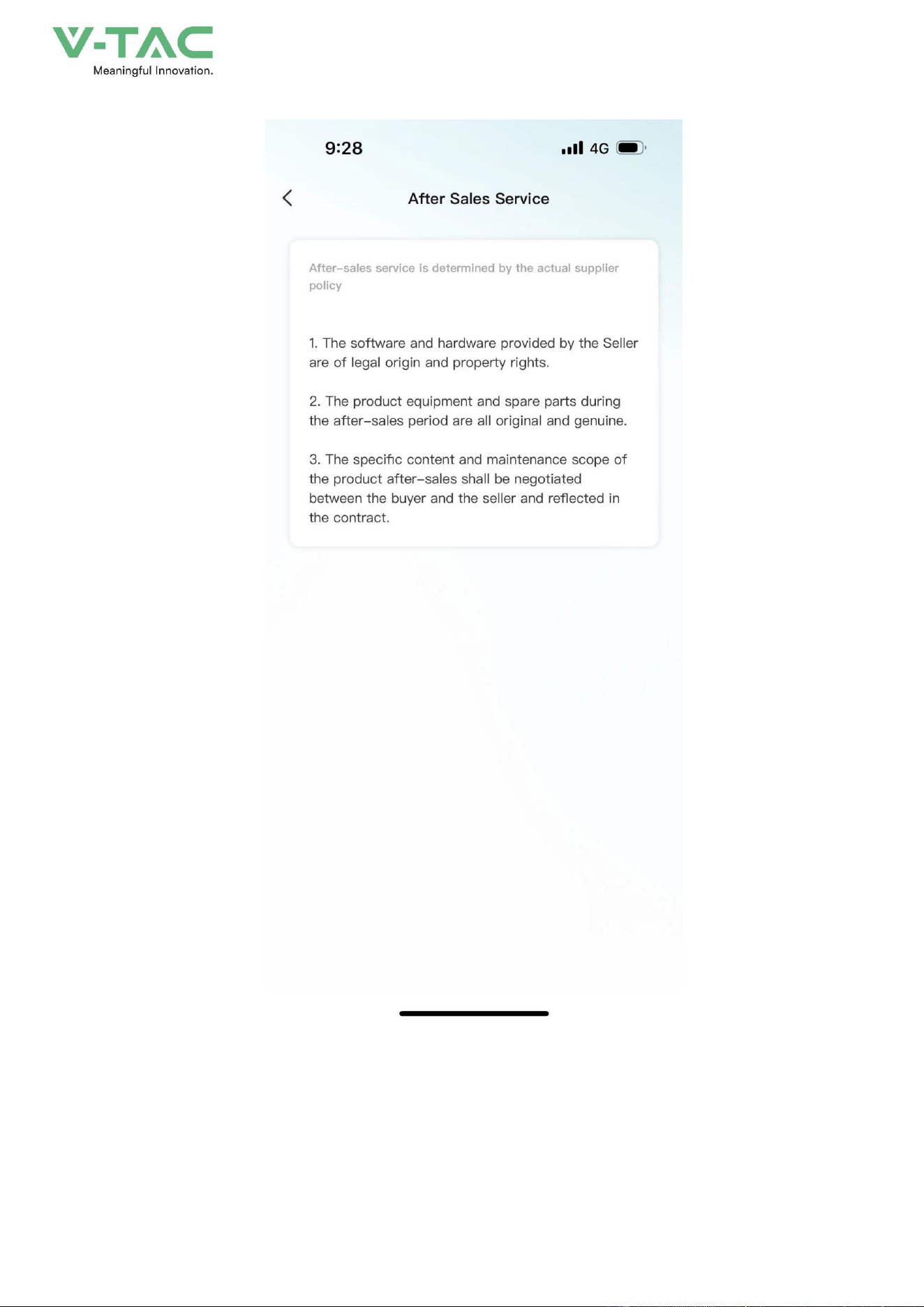
•
Click "after-sales services" and enter the after-sales services page to display the after-sales
services declaration of the current supplier.
66
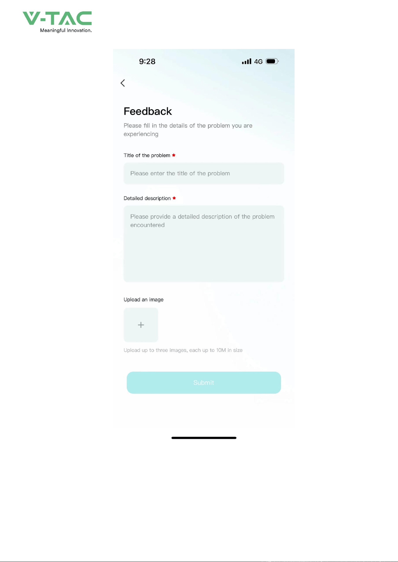
• Click "Feedback" to enter the feedback page. You can enter the current problem that needs
feedback and submit it.
67
7.4.4 Message
Click on the device or my page, the message icon above, you can enter the inbox page to view
the current notification or chat history.

68
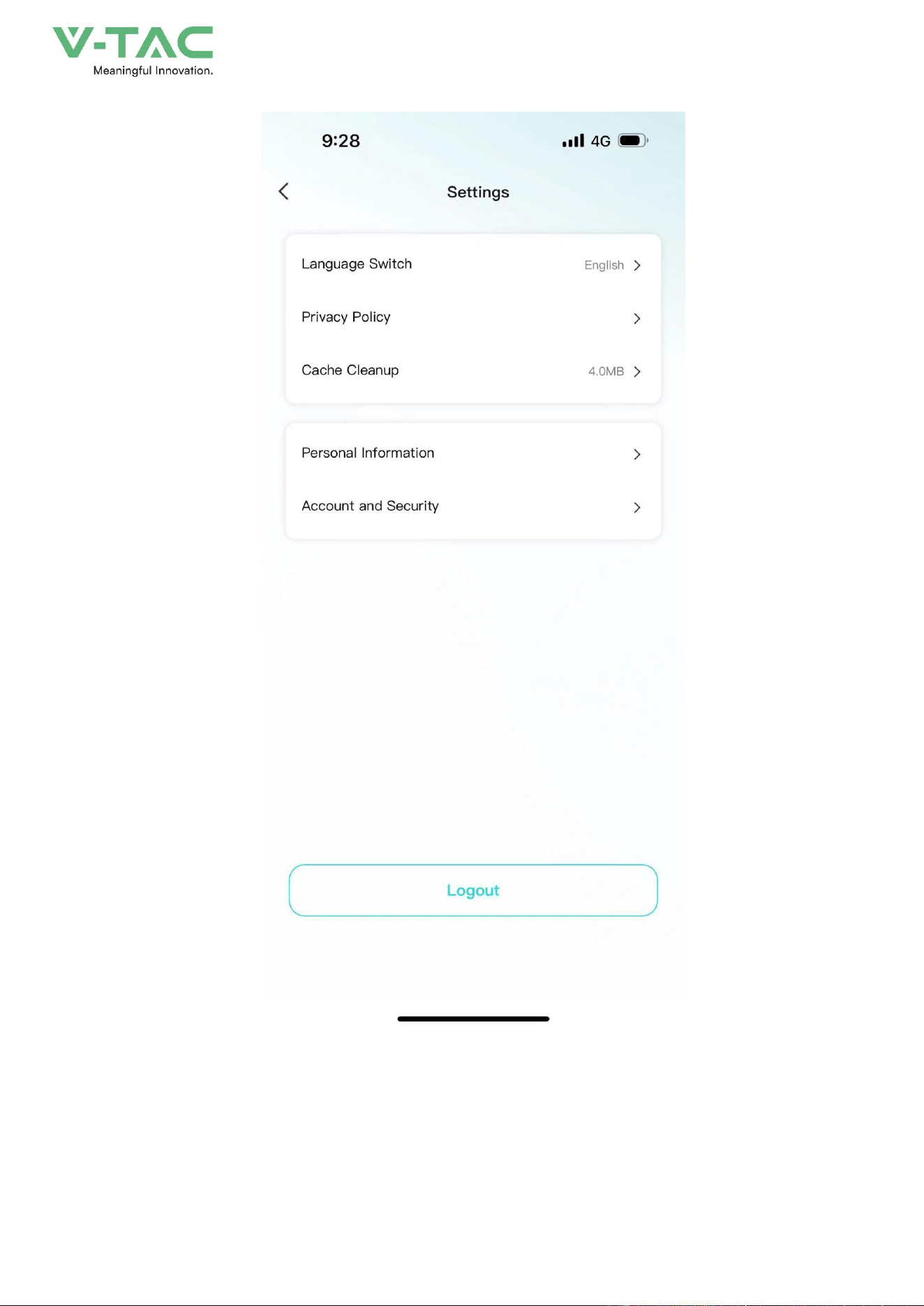
7.4.5 App settings
•
Click My Pages - Settings icon in the upper-right corner to enter the App Settings page.
• Settings page support: language switching, Privacy Policy, cache cleaning, personal
information, account and security.
69

70
8 Maintenance
8.1 Maintenance Guide
Correct maintenance is the key to keep the energy storage system running in optimum condition
and it will ensure a long service life for the energy storage system.
8.1.1Safety Precautions
* Before checking or maintenance, if the DC and AC sides have just been disconnected, it is
necessary to wait 10 minutes to ensure the device fully discharged. Measure with a voltmeter to
ensure that the power supply is switched off and in a safe condition before maintenance.
* At least 2 persons must be present at the same time during maintenance or troubleshooting.
In order to perform the maintenance of the energy storage system safely and successfully, it is
important to observe the relevant safety precautions, to use the necessary tools and test equipment,
and to operate by qualified maintenance personnel. Always observe the following safety procedures:
* Ensure that the energy storage system will not be reconnected accidentally.
* When operating, DO NOT wear any easily conductive object, such as rings, watches, etc. when
operating the energy storage system.
* When operating, cover the electrical components close to the operation area by insulating cloth.
* Inspection is required at the end of maintenance to ensure that the screws of maintained parts
have been tightened and without tools left inside the energy storage system.
8.1.2 Safety Precautions
To improve the efficiency and reliability of the energy storage system, perform the following
preventive maintenance operations periodically.
Before maintenance, first of all, it is necessary to shut down the energy storage system and
disconnect the breaker of DC side and AC side. The external power supply should be operated in the
following cases.
External Power Supply Requires to be Powered Down

71
External Power Supply Without Power-down Requirement
Check item
Check method
Cycle
Check item
Check method
Cycle
System
cleaning
1. Check the cleanliness of the electric cabin and battery cabin of the
energy storage system, and clean them in time.
2. Check the temperature of the heat sink as well as the surrounding
dust. If necessary, clean the heat sink by dust collector to avoid
affecting the normal operation of the heat sink.
Once every three
months/half year/one year
depending on the used
environment.
Terminals and
cables
connection
1. Check whether the terminal of main circuit is in poor connection
and whether the screws is overheating.
2. Check whether the screws of control end are loose, if so, tighten
them with a screwdriver.
3. Check whether there is any color change of the wiring copper bar
or screw.
4. Check whether there is scratch on the cable in contact with the
metal surface, if so, please maintain it in time.
5. Check whether the insulating wrapping tape of the cable terminals
is off, if so, please tie it up in time.
6. Check whether the cable connection is loose, and tighten it again
according to the specified torque.
Every three months once
Component
maintenance
1. Check the corrosion condition of all metal components.
2. Annual inspection for contactors (auxiliary switches, breakers and
micro breakers). Ensure them with good mechanical operation.
3. Check the operating parameters.
Every half to one year once

72
System
cleaning
Check the filter mesh and filter cotton of each part and clean or
replace it in time.
Once every
three
months/half
year/one year depending on
the used environment.
System
operating
condition and
environment
1. Listen to the operation sound of the energy storage system to see
if it is abnormal.
2. Check whether the operation parameters of the energy
storage system are normal, for detailed operation,
3. Observe whether the air inlet and outlet are normal and
whether there is any abnormal noise.
4. Check whether the heat generated by the cover of the energy
storage system is normal and monitor the heat generated by the
system, and the maximum temperature should not exceed the
maximum use ambient temperature of the energy storage system.
5. Check if key components such as air conditioning and lights are
functioning properly
6. Check whether filtration functions of all air inlet are
normal.
7. Check whether the humidity and dust of the environment around
the energy storage system are normal.
8. Check whether the temperature of the surrounding environment
meets the operation of the energy storage system.
Note: Ventilation of the air inlets must be checked. Otherwise, the
module may not be cooled efficiently, and causing the energy storage
system fault due to overheating.
Every half year once
Cabinet
maintenance
Observe the energy storage system for damage or deformation.
Check the warning signs and other device markings on the cabinet
and replace them n time if they are blurred or damaged.
Every half year once
Safety
Function
Simulate the halt operation and check whether the halt signal
communication is normal.
Every half to one year once
Software
maintenance
Check whether the parameter setting of each device on APP is
normal and is the same as the initial setting.
Every half year once
Door lock
maintenance
1. Check whether the door locks etc. of each door panel of the
energy storage system are normal and in good condition. If
necessary, lubricate the door lock holes appropriately.
2. Check if there are any foreign objects at the air conditioning
outlet
3. Regularly clean the dust and debris from the external air vents of
Every half year once
73
the air conditioner
* The table above is only the recommended routine maintenance cycle, the actual product should be
maintained based on the specific installation and use environment. The size of the power plant, the location, and
the site environment and other factors will affect the product's routine maintenance cycle.
* If the energy storage system is installed in a harsh environment with heavy wind and sand or dense dust,
please shorten the maintenance cycle and increase the frequency of maintenance.
8.2 Key Components Maintenance
Do not use any solvents, abrasives or corrosive materials to clean the energy storage system.
8.2.1 Battery Maintenance
Safety Precautions for Battery Maintenance
* The battery should be away from fire and all electrical equipment that is easy to cause sparks, so
as not to cause explosion.
* Do not short circuit the battery terminals. Short-circuiting the battery will cause burning.
* Do not open the battery to prevent the electrolyte from harming the human body.
Battery Maintenance
Regular maintenance should be performed to ensure the service life of the battery.
Check item
Check method
Cycle
Battery cycle
maintenance
The battery system should be fully charged and discharged periodically
to ensure the battery performance.
Once every three
months
74
When the battery voltage or SOC is in the following conditions, it is necessary to charge the energy storage
system in time according to the following recommended time, it is recommended to be charged to 40%~50%
SOC, the capacity loss caused by not replenishing the battery within the recommended time is not covered by
the warranty:
* 5%< battery SOC<10%: within 20 days .
* Battery SOC is 0 % or minimum cell voltage below 2.7V: within 5 days .
* The minimum cell voltage is less than 2.6V: within 2 days .
When the cell voltage is less than 2.5V, the recharge operation must be carried out by a professional
with skillful training, please contact the manufacturer to carryout the operation in time.
Battery
maintenance for
long
term storage
If the battery system is not used for more than 6 months, the battery
must be replenished to 40%~50% of SOC to ensure the battery
performance.
Once every six
months
Maintenance in
case of
system
failure or half
During the use of the system, if there is a halt for fault, and the halt time
is more than 1 month, you need to confirm the SOC status of the battery
system in advance. Ensure that the SOC is maintained at 40% ~ 50% state
to avoid the battery in a low SOC state for long-term
storage, and resulting in battery over-discharge.
Once every
month
Maintenance for
battery
pack
1. Check the battery case and cover for bulging, liquid leakage and
damage.
2. Check the connecting cables, terminals, etc. for corrosion and rust,
and the fastening bolts and nuts for looseness.
3. Check the surface temperature of the battery terminals and
battery case with thermal imager or other tools, which should be below
45
℃
.
4. For the temporarily unused battery pack, regular recharge it within
three months.
5. Batteries that have been in a charging status for a long time should be
forcibly discharged once every month.
6. Battery packs equipped with BMS should pay special attention to
whether the cell
’
s voltage difference, cell temperature difference is too
large, and whether the insulation resistance is normal.
7. Regularly check whether the battery temperature, voltage, current,
SOC and other information are normal via APP.
Once every three
to six months

75
Battery Replacement Announcements
* For battery replacement, please consult a professional engineer.
* The replaced battery must be with the same capacity, type and manufacturer of the energy storage
system.
* The replaced old batteries should not be discarded at will, they should be disposed by professional
recycling organization.

76
9 Maintenance
Warning! Improper decommissioning may cause damage to the equipment and/or
battery inverter.
Before maintenance, ensure that OHA-100 is decommissioned according to relevant provisions.
Note: All maintenance work shall comply with local applicable regulations and standards.
The USB-CAN port of OHA has the functions of upgrading firmware and recording battery data, which
can be used as an auxiliary tool.
To ensure safe operation, all plug connections must be checked. If necessary, relevant operators
shall press them back into place at least once a year.
The following inspection or maintenance must be carried out once a year:
• General visual inspection
• Check all tightened electrical connections. Check the tightening torque according to the values
in the following table. Loose connections must be retightened to the specified torque.
Connection mode
Tightening torque
high-voltage BMS box grounding
4.5Nm
Fixing the lug of the high-voltage BMS box
1.2Nm
Fixing the lug of the battery module
1.2Nm
• Using the monitoring software, check whether the SoC, SoH, battery voltage and temperature
of the battery module are abnormal.
• Shut down and restart OHA-100 once a year.
Note: If the system is installed in a polluted environment, maintenance and cleaning must be
carried out at short intervals.
Note: Clean the battery rack with a dry-cleaning cloth. Ensure that no moisture comes into
contact with the battery connections. Do not use solvents.
77
Attention:
1. Do not dispose of batteries and rechargeable batteries as domestic waste! You are
legally obliged to return used batteries and rechargeable batteries.
2. Waste batteries may contain pollutants that can damage the environment or your health if improperly stored
or handled.
3. Batteries also contain iron, lithium and other important raw materials, which can be recycled.
Do not dispose of batteries as household waste!
Legal Statement
The information contained in the document is the property of V-TAC Europe Ltd.
All information shall not be published in whole or in part without the written permission of V-TAC Europe Ltd.
