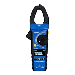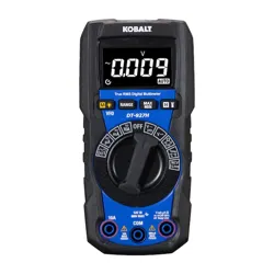

ITEM #5995674
MODEL #DT-927H
AUTO-RANGE MULTIMETER
WITH FLASHLIGHT
Español p.28
True RMS Digital Multimeter
CAT III
600V MAX
COM
10A
500mA
MAX
FUSED
V mA µA
CAP Hz%
Temp Live
VFD
MAX
10A
FUSED
RANGE
MAX
MIN
DT-927H
KOBALT and logo design are
trademarks or registered trademarks
of LF, LLC. All rights reserved.
Serial Number
Purchase Date
SG24724
ATTACH YOUR RECEIPT HERE
Thank you for purchasing this KOBALT product.
Questions problems or missing parts?
Before returning. contact us on:
888-356-2258
, 8 a.m. - 8 p.m., EST, Monday - Sunday.
or
2 3
TABLE OF CONTENTS PRODUCT SPECIFICATIONS
GENERAL SPECIFICATIONS
Insulation Class 2, Double insulation
Display 4,000 counts Negative display
Polarity
Automatic (no indication for positive polarity)
Minus symbol “-“ is displayed for negative
polarity
Overrange
indication
“OL” is displayed
Crest Factor
3 at full scale up to 300 V, decreasing linearly
to <1.5 at 600 V
Low Battery
Indication
“ ” is displayed if battery voltage drops below
operating voltage
Measurement Rate 3 times per second, nominal
Auto Power O Approx.15 minutes
Imput Impedance >10MΩ VDC & >10MΩ VAC
AC Response True RMS
ACV Bandwidth
50/60 Hz (All wave); 45 Hz to 1000 Hz (Sine
wave)
Battery Two AAA 1.5 V batteries
Fuse
mA/μA ranges: 0.5 A 600 V ceramic fast blow;
Breaking Capacity: 10 kA/ 600 V AC/DC
A range: 10 A/600 V ceramic fast blow;
Breaking Capacity: 10 kA/600 V AC/DC
Operating
Environment
32°F to 122°F (0°C to 50°C) at <70% relative
humidity
Storage
Environment
14°F to 140°F (-10°C to 60°C) at <80% relative
humidity
Operating Altitude 7000 ft (2000 m) maximum
Net Weight Approx.0.75 lbs. (342 g)
Dimensions Approx.6.0x2.9x1.7 in. (153.6x74.5x43 mm)
Safety
Conforms to: UL STD 61010-1,61010-2-033
Certied to: CSA STD C222# 61010-1. 61010-
2-033: EN 61010-1. 61010-2-033
Product Specications ...........................................................................3
Package Contents .................................................................................7
Safety Information ................................................................................11
Operating Instructions ..........................................................................13
Care and Maintenance .........................................................................26
Troubleshooting ....................................................................................27
Warranty ...............................................................................................27
4 5
FUNCTION RANGE RESOLUTION ACCURACY
DC Voltage
400 mV 0.1 mV
±(1.0%+3 digits)
4 V 0.001 V
40 V 0.01 V
400 V 0.1 V
600 V 1 V
AC Voltage
(50 Hz to 400
Hz)
4 V 0.001 V
±(1.0%+3 digits)
40 V 0.01 V
400 V 0.1 V
600 V 1 V
All AC voltage ranges are specied from 5% of
range to 100% of range.
Variable frequency Drive Test AC voltage range:
100 V-600 V.
DC Current
400 μA 0.1 μA
±(1.0%+3 digits)
4000 μA 1 μA
40 mA 0.01 mA
400 mA 0.1 mA
4 A 0.001 A
±(1.2%+3 digits)
10 A 0.01 A
10 A: 30 sec max with reduced accuracy.
PRODUCT SPECIFICATIONS PRODUCT SPECIFICATIONS
FUNCTION MAXIMUM INPUT
Voltage AC or DC 600 VDC/AC rms
mA AC/DC 500 mA 600 V fast acting fuse
A AC/DC 10 A 600 V fast acting fuse
Frequency, Resistance,
Temperature, Capacitance, Diode
Test, Continuity
600 V DC/AC rms
Input Limits
FUNCTION RANGE RESOLUTION ACCURACY
AC Current
(50 Hz to 60
Hz)
400 μA 0.1 μA
±(1.2% + 3 digits)
4000 μA 1 μA
40 mA 0.01 mA
400 mA 0.1 mA
4 A 0.001 A
±(1.8% + 5 digits)
10 A 0.01 A
10 A: 30 sec max with reduced accuracy.
All AC voltage ranges are specied from 5% of
range to 100% of range.
Resistance
400 Ω 0.1 Ω
±(1.5%+5 digits)
4 kΩ 0.001 kΩ
40 kΩ 0.01 kΩ
400 kΩ 0.1 kΩ
4 MΩ 0.001 MΩ
40 MΩ 0.01 MΩ ±(2.5%+20 digits)
Capacitance
99.99 nF 0.01 nF ±(4.5%+20 digits)
999.9 nF 0.1 nF ±(4.5%+10 digits)
9.999 μF 0.001 μF
±(3.5%+5 digits)99.99 μF 0.01 μF
999.9 μF 0.1 μF
9.999 mF 1 μF
±(5%+5 digits)
99.99 mF 10 μF
Frequency
(Electrical)
10.00-10kHz 0.01 Hz ±(1.2% reading)
Sensitivity: 10 V rms
Duty Cycle
0.1 to 99.9% 0.1% ±(1.2% + 2 digits)
Pulse width: 100 μs-100 ms, Frequency:
5 Hz to 10 kHz.
Frequency (AC
Current) (Auto-
ranging)
45 Hz to 1 kHz ±(1.0% + 5 digits)
6 7
FUNCTION TESTING CONDITION READING
Diode
Forward DCA is approx.1 mA,
open circuit Voltage MAX. 3 V
Forward voltage drop of
Diode
Continuity
Test current MAX. 1.5 mA
Buzzer makes a long
sound, While resistance
is less than (50 Ω)
Input Protection: 600 V dc or 600 V ac rms.
Note:
Accuracy is stated at 18 to 28°C (65 to 83°F) and less than 75%
RH.
Note:
Accuracy specications consist of two elements:
• (% reading)-This is the accuracy of the measurement circuit.
• (+ digits)-This is the accuracy of the analog to digital converter.
FUNCTION RANGE RESOLUTION ACCURACY
Temperature
-20 to
1000°C
1°C ±(3% + 3°C)
-4 to 1832°F 1°F ±(3% + 5°F)
Sensor: Type K Thermocouple.
Input Protection: 600 V dc or 600 V ac rms.
Square
Wave Output
Frequency
(Manual-ranging)
50,100,200,300,400,500,600,
700,800,900,1000,2000,3000,
4000,5000 Hz
±(1.0% + 5 digits)
PRODUCT SPECIFICATIONS PACKAGE CONTENTS
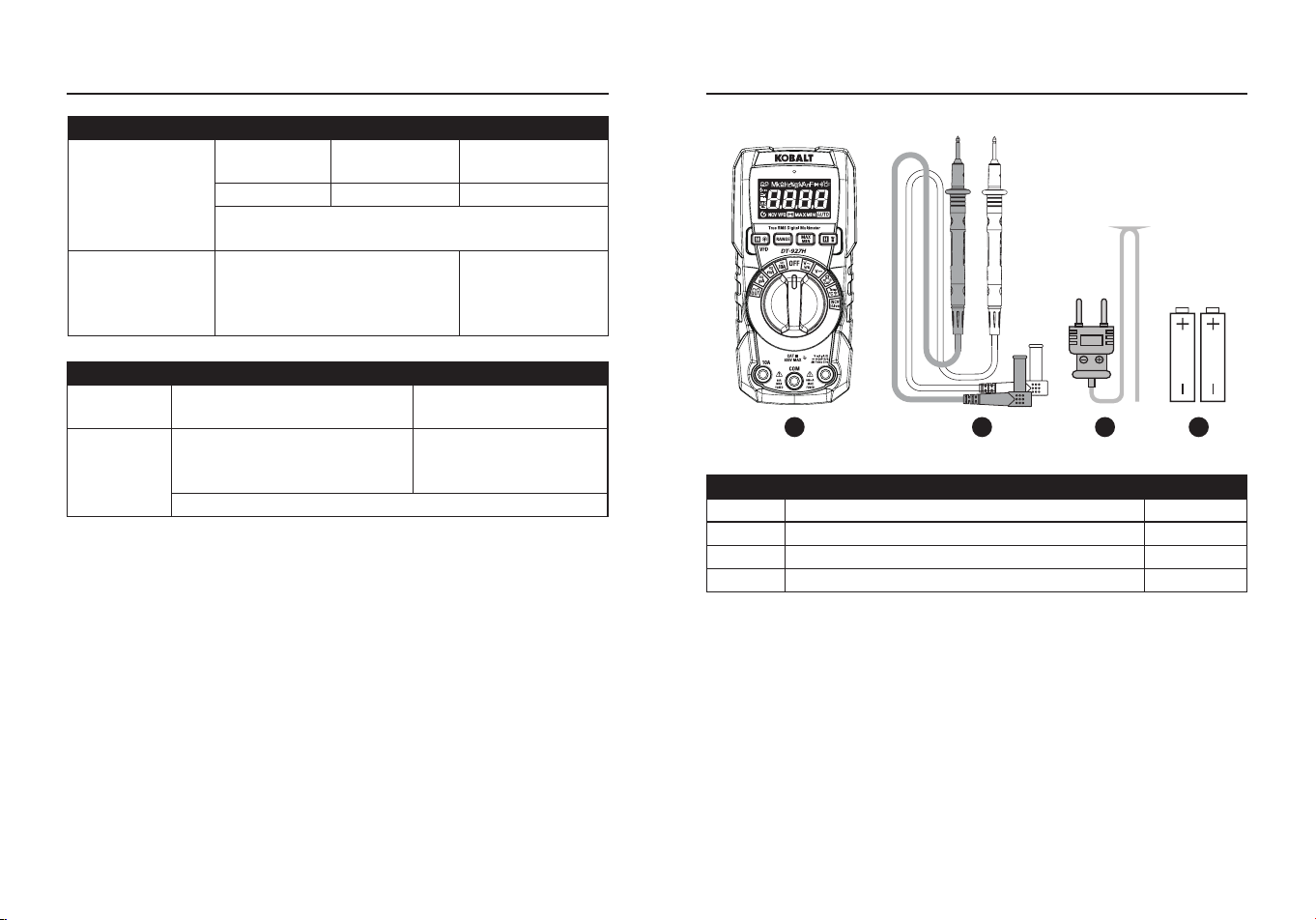
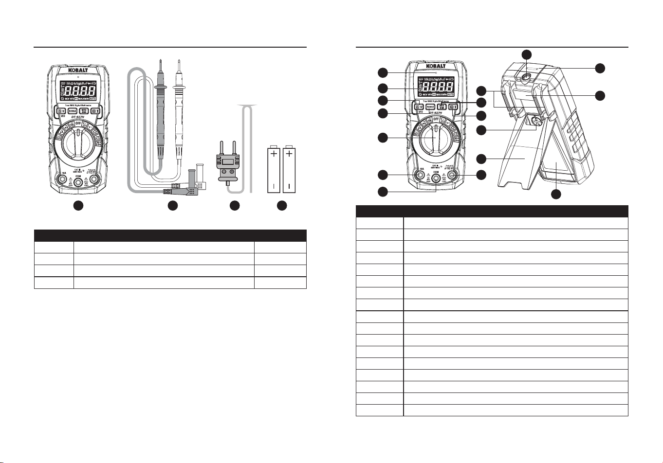
PART DESCRIPTION QUANTITY
A Meter 1
B Test leads 1
C Type K temperature probe 1
D 1.5-volt battery 2
A B C D
8 9
Te
s
t
o
n
k
n
o
w
n
l
i
v
e
c
i
r
c
u
i
t
b
e
f
o
r
e
e
a
c
h
u
s
e
N
o
n
-
C
o
n
t
a
c
t
V
o
l
t
a
g
e
D
e
t
e
c
t
o
r
WARNING
100 to 600VA
C
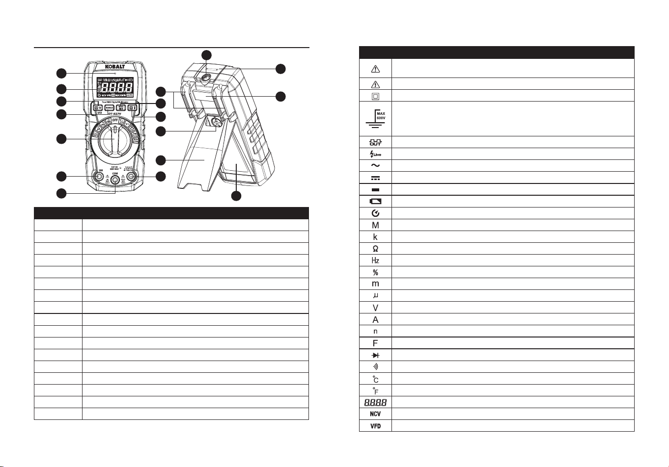
PACKAGE CONTENTS
A
B
C
E
N
L
M
K
Q
F
O
P
D
G
H
I
J
PART DESCRIPTION
A Non-Contact Voltage Indicator
B LCD Display
C Mode/VFD/Backlight Control
D RANGE Button
E MAX/MIN Button
F HOLD and Flashlight Button
G Function Switch
H 10 A Input Jack
I COM Input Jack
J Positive Input Jack
K Flashlight Indicator
L Non-Contact Voltage Detector
M Mount for OptionalMagnetic Hanger
N Test lead storage and holder
O Battery Cover Lock
P Kickstand
Q Battery Cover
NOTE
: Remove the plastic lm on the LCD display before use.
Symbols
PART DESCRIPTION
Potential danger. Indicates the user must refer to the manual
for important safety information.
Indicates hazardous voltages may be present.
Equipment is protected by double or reinforced insulation.
Indicates the terminal(s) so marked must not be connected
to a circuit where the voltage with respect to earth ground
safety rating of the meter exceeds the maximum safety rating
of the meter.
Square Wave Output
Live Line Test
AC voltage or current
DC voltage or current
Minus sign
Low battery
Auto Power O
Mega (10
6
)
kilo (10
3
)
Ohms
Hertz (Frequency)
Duty cycle
milli (10
-3
)
Micro (value x 10
-6
)
Volts
Amperes
Nano (value x 10
-9
)
Farads
Diode test
Continuity
Degree Celsius
Degree Fahrenheit
Measurement Reading
Non-Contact Voltage
Variable Frequency Drive Test AC Voltage
10 11
Autohold
Maximum
Minimum
Auto Ranging
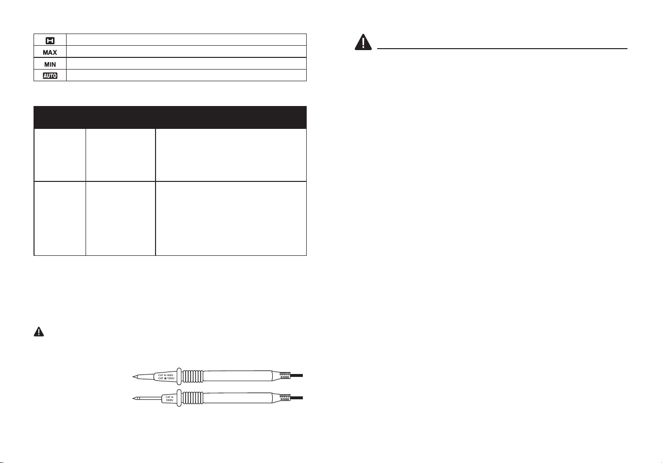
Test Leads
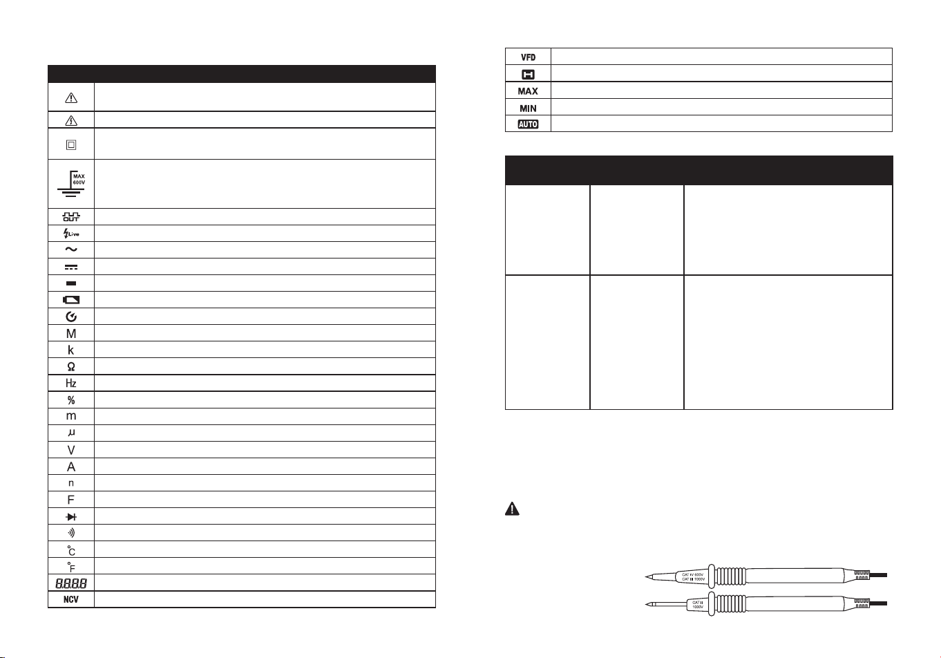
WARNING:
Operation is limited to CAT II applications when the
insulated tips are removed from one or both test probes. Refer to Input
Limits section in this manual for Maximum voltage ratings.
Insulated Tip On
Insulated Tip Removed
CATEGORY
RATING
BRIEF
DESCRIPTION
TYPICAL APPLICATIONS
CAT II
Single phase
receptacles
and connected
loads.
- Household appliances, power tools.
- Outlets more than 30ft (10m) from a
CAT III source.
- Outlets more than 60ft (20m) from a
CAT IV source.
CAT III
Three phase
circuits and
single phase
lighting circuits
in commercial
buildings.
- Equipment in xed installations such
as 3-phase motors, switchgear and
distribution panels - Lighting circuits
in commercial buildings.
- Feeder lines in industrial plants.
- Any device or branch circuit that is
close to a CAT III source.
Safety Category Ratings
The measurement category (CAT) rating and voltage rating is
determined by a combination of the meter,test probes and any
accessories connected to the meter and test probes. The combination
rating is the LOWEST of any individual component.
SAFETY INFORMATION
WARNINGS
●Please read and understand this entire manual before using this
product.
●Before changing functions using the selector switch, always
disconnect the test leads from the circuit under test.
●Ensure that the test leads are fully seated in the input jacks and keep
ngers away from the metal probe tips when taking measurements.
●Use only certied test leads with the proper safety category rating.
●Verify operation before using meter by measuring a known live
voltage.
●Use caution on live circuits. Voltages above 30V AC rms, 42V AC
peak, or 60V DC pose a shock hazard.
●Comply with all applicable safety codes. Use approved personal
protective equipment when working near live electrical circuits-
particularly with regard to arc-ash potential.
●Do not use if the meter or test leads appear damaged.
●Do not use the meter or near explosive vapors, dust or gasses.
●Do not use the meter in wet or damp environments or during electrical
storms.
●Do not use the meter if it operates incorrectly. Protection may be
compromised.
●Do not operate meter while Low Battery warning is on. Replace
batteries immediately.
●Do not apply voltage or current that exceeds the meter's maximum
rated input limits.

12 13
"This device complies with part 15 of the FCC Rules. Its Operation is
subject to the following two conditions: (1) This device may not cause
harmful interference, and (2) this device must accept any interference
received, including interference that may cause undesired operation."
Lowe’s Home Centers LLC
1000 Lowe’s Blvd.
Mooresville, NC 28117
1-888-3KOBALT (1-888-356-2258)
This equipment has been tested and found to comply with the limits
for a Class B digital device, pursuant to part 15 of the FCC Rules.
These limits are designed to provide reasonable protection against
harmful interference in a residential installation. This equipment
generates, uses and can radiate radio frequency energy and, if not
installed and used in accordance with the instructions, may cause
harmful interference to radio communications. However, there is no
guarantee that interference will not occur in a particular installation. If
this equipment does cause harmful interference to radio or television
reception, which can be determined by turning the equipment o and
on, the user is encouraged to try to correct the interference by one or
more of the following measures:
1. Reorient or relocate the receiving antenna.
2. Increase the separation between the equipment and receiver.
- Connect the equipment into an outlet on a circuit dierent from that to
which the receiver is connected.
- Consult the dealer or an experienced radio/TV technician for help.
"
CAUTION
: Changes or modications not expressly approved by the
party responsible for compliance could void the user's authority to
operate the equipment."
Users of this product are cautioned not to make modications or
changes. Doing so may void the compliance of this product with
applicable laws and regulatory requirements and may result in the loss
of the user's authority to operate the equipment.
PRODUCT COMPLIANCE OPERATING INSTRUCTIONS
Autoranging/Manual Range Selection
●To Power ON the meter rotate the Function Selector switch from the
OFF setting to any measurement setting. To Power OFF the meter
rotate the Function Selector switch to the OFF setting.
●When the meter is rst turned on, it automatically goes into
Autoranging.
●This automatically selects the best range for the measurements being
made and is generally the best mode for most measurements.
●For measurement situations requiring that a range be manually
selected, perform the following:
1.Press the RANGE Button, the “AUTO” display indicator will turn o.
2.Press the RANGE Button to step through the available ranges until
you select the range you want.
3.To exit the Manual Ranging mode and return to Autoranging, press
and hold the RANGE Button for 2 seconds.
Note:
Manual ranging does not apply for the Capacitance and
Frequency functions.
MAX/MIN
Note:
When using the MAX/MIN function in Autoranging mode, the
meter will “lock” into the range that is displayed on the LCD when MAX/
MIN is activated, if a MAX/Min reading exceeds that range, an “OL” will
be displayed, Select the desired range before entering MAX/MIN mode.
●Press the
MAX/MIN
Button to activate the MAX/MIN recording mode,
the display icon “
MAX
” will appear, the meter will display and hold the
maximum reading and will update only when a new “max” occurs.
●Press the
MAX/MIN
Button again and the display icon “
MIN
” will
appear, the meter will display and hold the minimum reading and will
update only when a new “min” occurs.
●To exit MAX/MIN mode press and hold the MAX/MIN Button for 2
seconds.
14 15
OPERATING INSTRUCTIONS
Backlit Controls
All controls are backlit for low light visibility.
MODE/VFD/Backlight
●Press MODE Button the selection of double measured functions
which are present at display is possible, in particular this key is active
in V Ω CAP Position to select among Resistance Test, Diode
Test, Continuity Test, Capacitance Test and VFD Test and in Current
position to select between AC or DC current measurements.
●Press the
MODE
Button for >1 second to turn on or o the Blacklight
(Rotary Switch backlight) function, the backlight will automatically
power OFF after 3 minutes of inactivity.
HOLD/Flashlight
●The hold function freezes the reading in the display, press the HOLD
Button momentarily to activate or to exit the HOLD function.
●Press the HOLD Button for >1 second to turn on or o the Flashlight
function.
Auto Power O:
●The auto o feature will turn the meter o after 15 minutes.
●To disable the auto power o feature, hold down the Mode button and
turn the meter on.
Note:
The above data is only for reference.
OPERATING INSTRUCTIONS
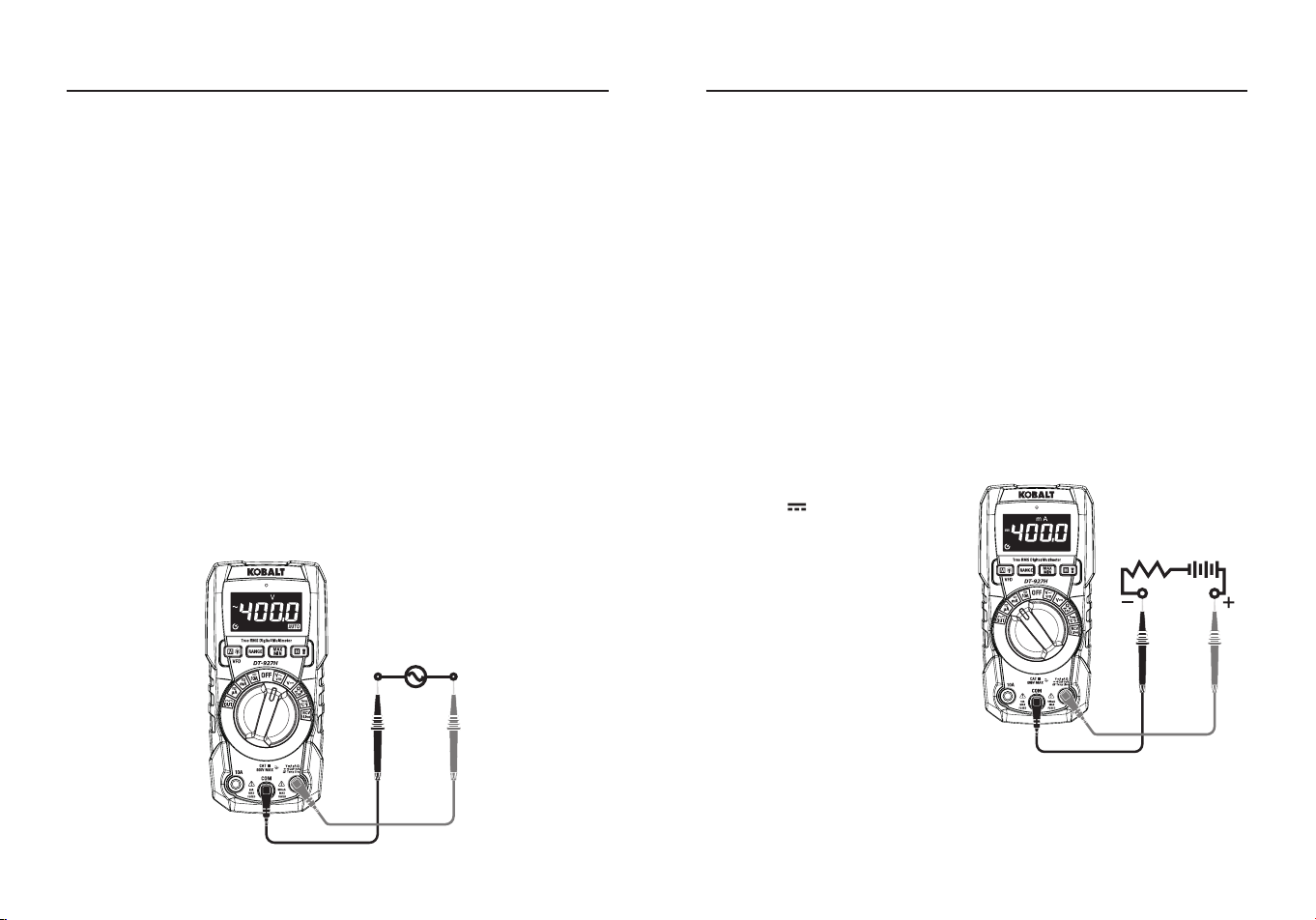
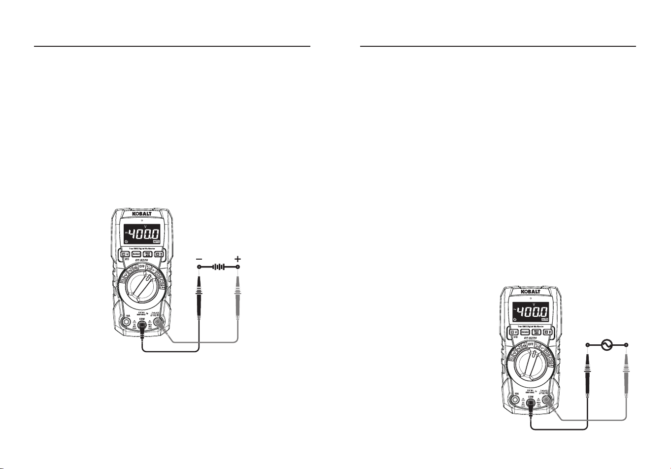
DC Voltage Measurement
CAUTION:
Do not measure DC voltages if a motor on the circuit is
being switched ON or OFF. Large voltage surges may occur that can
damage the meter.
●Set the rotatory function switch to the
VDC
Position.
●Insert the black test lead banana plug into the negative
COM
Input
Jack; Insert the red test lead banana plug into the
Positive
Input
Jack.
●Touch the black test probe tip to the negative side of the circuit; Touch
the red test probe tip to the positive side of the circuit.
●Read the voltage on the LCD display.
16 17
AC Voltage (Frequency, Duty Cycle) Measurement
WARNING:
Risk of Electrocution. The probe tips may not be long
enough to contact the live parts inside some 240 V outlets for
appliances because the contacts are recessed deep in the outlets. As
a result, the reading may show 0 volts when the outlet actually has
voltage on it. Make sure the probe tips are touching the metal contacts
inside the outlet before assuming that no voltage is present.
CAUTION:
Do not measure AC voltages if a motor on the circuit is
being switched ON or OFF. Large voltage surges may occur that can
damage the meter.
●Set the rotatory function switch to the
VAC/VFD
Position.
●Insert the black test lead banana plug into the negative
COM
Input
Jack; Insert the red test lead banana plug into the
Positive
Input Jack.
●Touch the black test probe tip to the negative side of the circuit; Touch
the red test probe tip to the “hot” side of the circuit.
●Read the voltage on the LCD display.
●Press the
MODE
Button to indicate “
Hz
”.
●Press the
MODE
Button again to indicate “
%
”.
●Press the
MODE
Button again to indicate
VFD
.
●Read the AC Voltage, Hz, % and VFD Voltage in the display.
OPERATING INSTRUCTIONS OPERATING INSTRUCTIONS
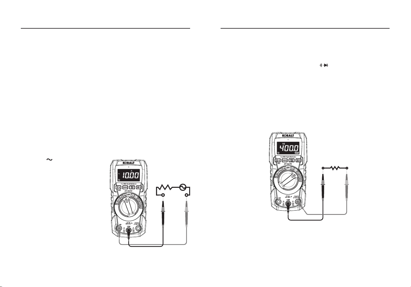
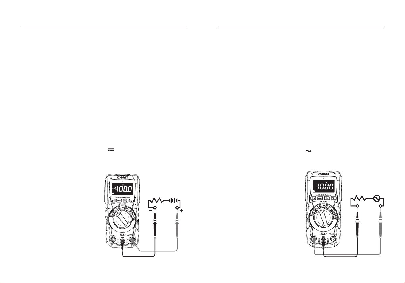
DC Current Measurement
CAUTION:
Do not make 10A current measurements for longer than
30 seconds. Exceeding 30 seconds may cause damage to the meter
and/or the test leads. When measuring currents greater than 4 A, a
measurement time of 30 seconds followed by 10 minutes of recovery
time is recommended.
●Insert the black test lead banana plug into the negative
COM
Input
Jack.
●For current measurements up to
4000 μA DC
, set the function switch
to the
μA
Position and insert the red test lead banana plug into the
μA/mA
Input Jack.
●For current measurements up to
400 mA DC
, set the function switch
to the
mA
Position and insert the red test lead banana plug into the
μA/mA Input Jack.
●For current measurements up to
10 A DC
, set the function switch to
the
10 A
Position and insert the red test lead banana plug into the
10
A
Input Jack.
●Press the
MODE
Button to
indicate “ ” on the display.
●Remove power from the circuit
under test, then open up the
circuit at the point where you
wish to measure current.
●Touch the black test probe tip to
the negative side of the circuit;
Touch the red test probe tip to
the positive side of the circuit.
●Apply power to the circuit.
●Read the current in the display.
18 19
AC Current (Frequency, Duty Cycle) Measurement
CAUTION:
Do not make 10 A current measurements for longer than
30 seconds. Exceeding 30 seconds may cause damage to the meter
and/or the test leads. When measuring currents greater than 4 A, a
measurement time of 30 seconds followed by 10 minutes of recovery
time is recommended.
●Insert the black test lead banana plug into the negative
COM
Input
Jack.
●For current measurements up to
4000 μA
AC
, set the function switch
to the
μA
Position and insert the red test lead banana plug into the
μA/mA
Input Jack.
●For current measurements up to
400 mA
AC
, set the function switch
to the
mA
Position and insert the red test lead banana plug into the
μA/mA
Input Jack.
●For current measurements up to
10 A AC
, set the function switch to
the
10 A
Position and insert the red test lead banana plug into the
10
A
Input Jack.
●Press the
MODE
Button to
indicate “ ” on the display.
●Press the
MODE
Button to
indicate “
Hz
”.
●Press the
MODE
Button again to
indicate “
%
”.
●Remove power from the circuit
under test, then open up the
circuit at the point where you
wish to measure current.
●Touch the black test probe tip
to the neutral side of the circuit;
Touch the red test probe tip to
the “hot” side of the circuit.
●Apply power to the circuit.
●Read the current in the display.
OPERATING INSTRUCTIONS OPERATING INSTRUCTIONS
Resistance Measurement
WARNING:
To avoid electric shock, disconnect power to the unit
under test and discharge all capacitors before taking any resistance
measurements. Remove the batteries and unplug the line cords.
●Set the rotatory function switch to the Ω CAP Position.
●Insert the black test lead banana plug into the negative
COM
Input
Jack; Insert the red test lead banana plug into the
Positive
Input
Jack.
●Press the
MODE
Button to indicate “
Ω
” on the display.
●Touch the test probe tips across the circuit or part under test, it is best
to disconnect one side of the part under test so the rest of the circuit
will not interfere with the resistance reading.
●Read the resistance in the display.
20 21
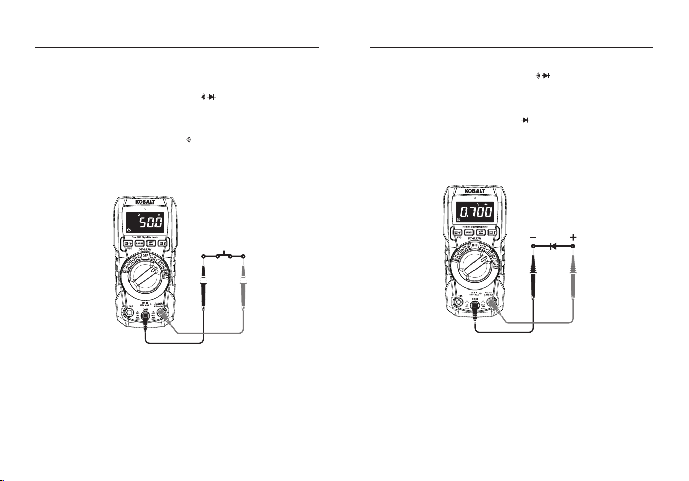
Continuity Check
WARNING:
To avoid electric shock, never measure continuity on
circuits or wires that have voltage on them.
●Set the rotatory function switch to the Ω CAP Position.
●Insert the black test lead banana plug into the negative
COM
Input
Jack; Insert the red test lead banana plug into the
Positive
Input
Jack.
●Press the
MODE
Button to indicate “ ” and “
Ω
” on the display.
●Touch the test probe tips to the circuit or wire you wish to check.
●If the resistance is less than approximately 50 Ω, the audible signal
will sound; if the circuit is open, the display will indicate “
OL
”.
OPERATING INSTRUCTIONS
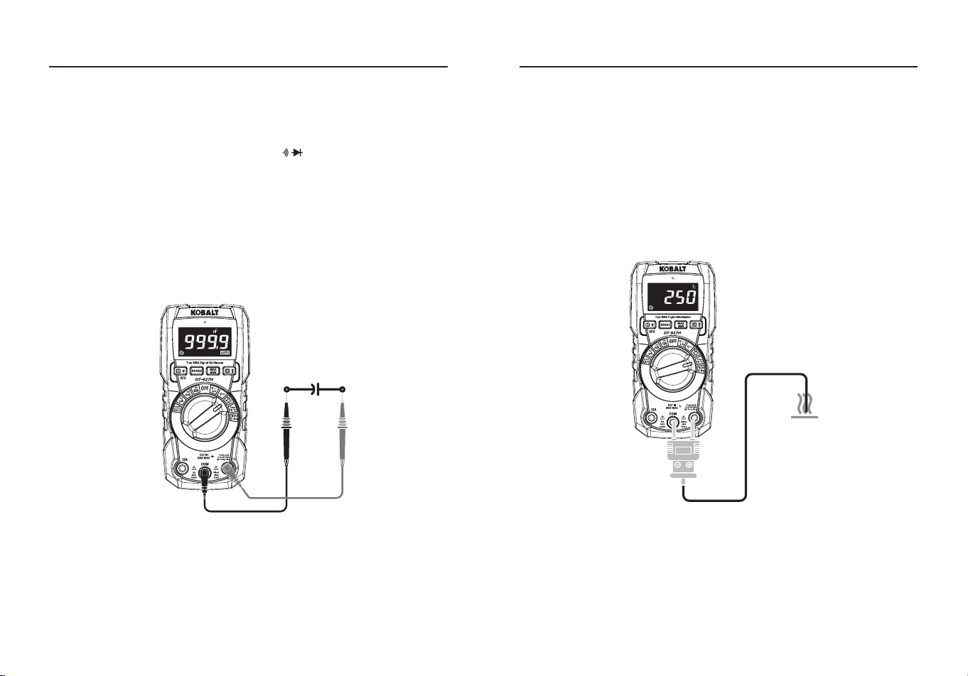
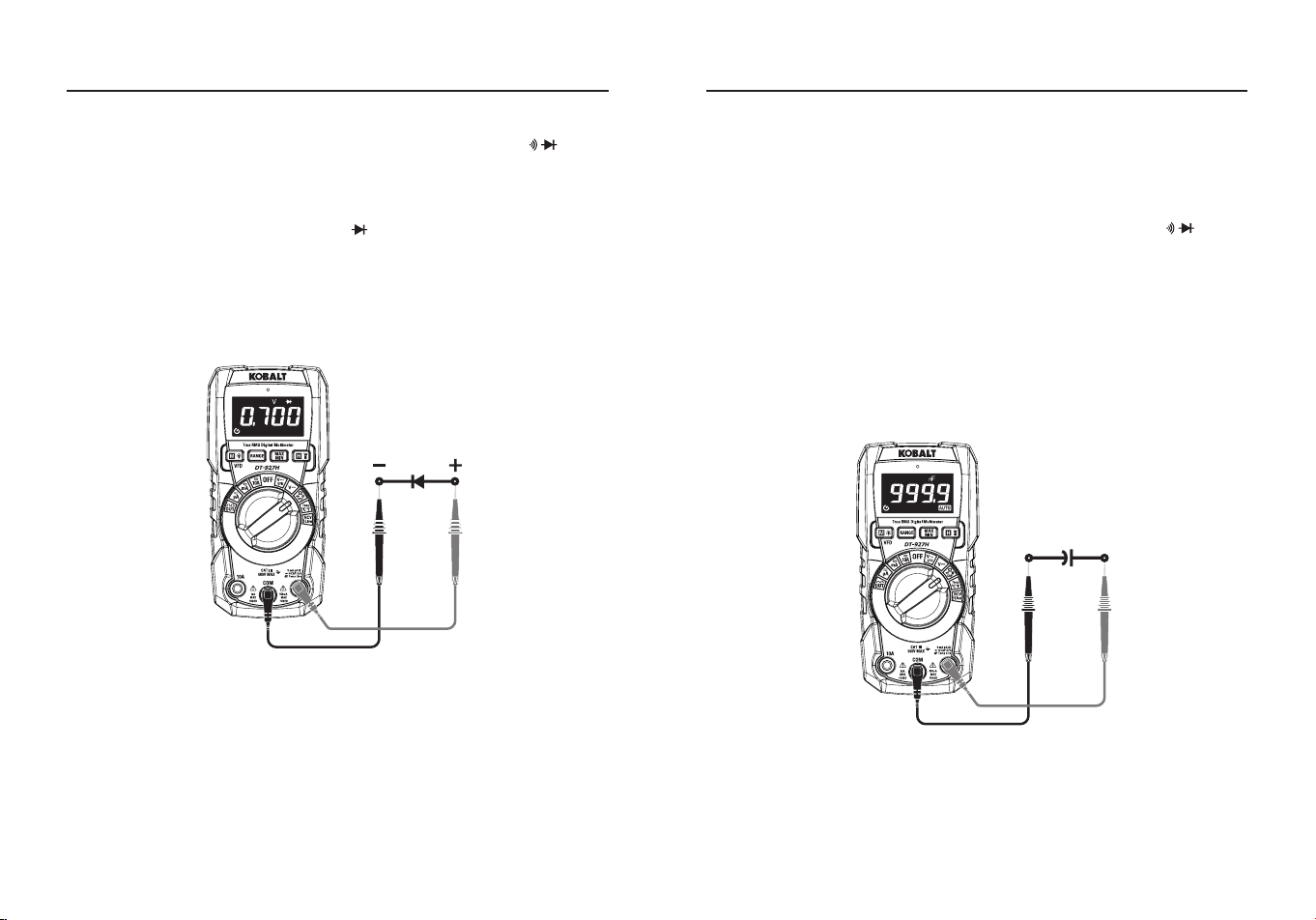
Diode Test
●Set the rotatory function switch to the Ω CAP Position.
●Insert the black test lead banana plug into the negative
COM
Input
Jack; Insert the red test lead banana plug into the
Positive
Input
Jack.
●Press the
MODE
Button to indicate “ ” and “
V
” on the display.
●Touch the test probes to the diode under test.
●Forward voltage will typically indicate 0.400 to 0.700 V; Reverse
voltage will indicate “
OL
”; Shorted devices will indicate near 0 V and
an open device will indicate “
OL
” in both polarities.
OPERATING INSTRUCTIONS
22 23
Capacitance Measurement
WARNING:
To avoid electric shock, disconnect power to the unit
under test and discharge all capacitors before taking any capacitance
measurements. Remove the batteries and unplug the line cords.
●Set the rotatory function switch to the Ω CAP Position.
●Insert the black test lead banana plug into the negative
COM
Input
Jack; Insert the red test lead banana plug into the
Positive
Input
Jack.
●Press the
MODE
Button to indicate “
nF
” on the display.
●Touch the test leads to the capacitor to be tested.
●The test may take up to 30s or more for large capacitors to charge,
wait until the readings settle before ending the test.
●Read the capacitance value in the display.
OPERATING INSTRUCTIONS OPERATING INSTRUCTIONS
Temperature Measurement
WARNING:
Do not touch the temperature probe to live circuits.
●Set the function switch to the
Temp
Position.
●Press the
MODE
Button to indicate
°C
or
°F
.
●Connect the temperature probe to the banana plug adapter, note the
-
and
+
markings on the adapter.
●Connect the adapter to the meter, making sure the - side goes into
the
COM
Input Jack and the + side goes into the
Positive
Input Jack.
●Touch the tip of the temperature probe to the object being measured.
●Read the temperature on the LCD display.
24 25
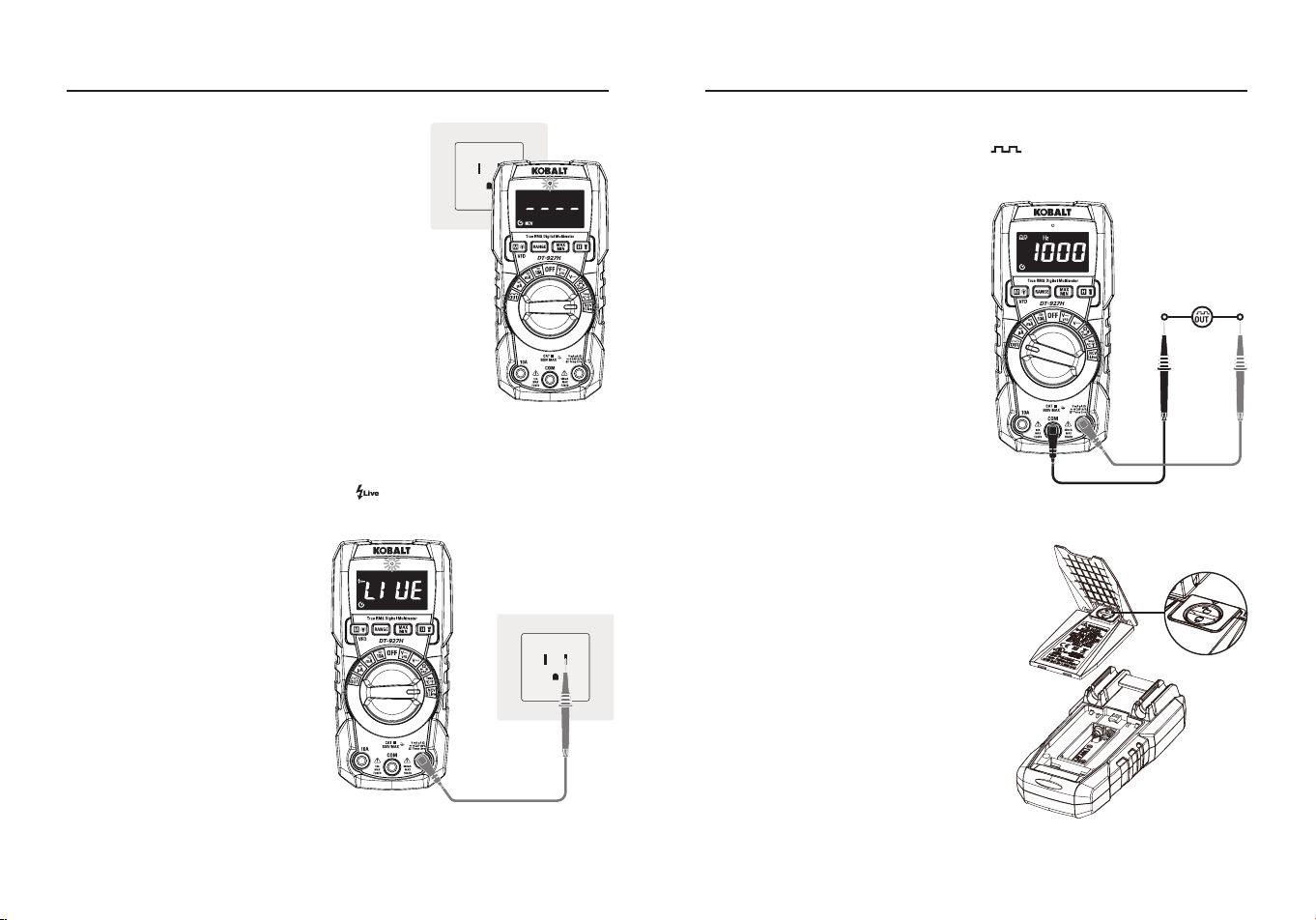
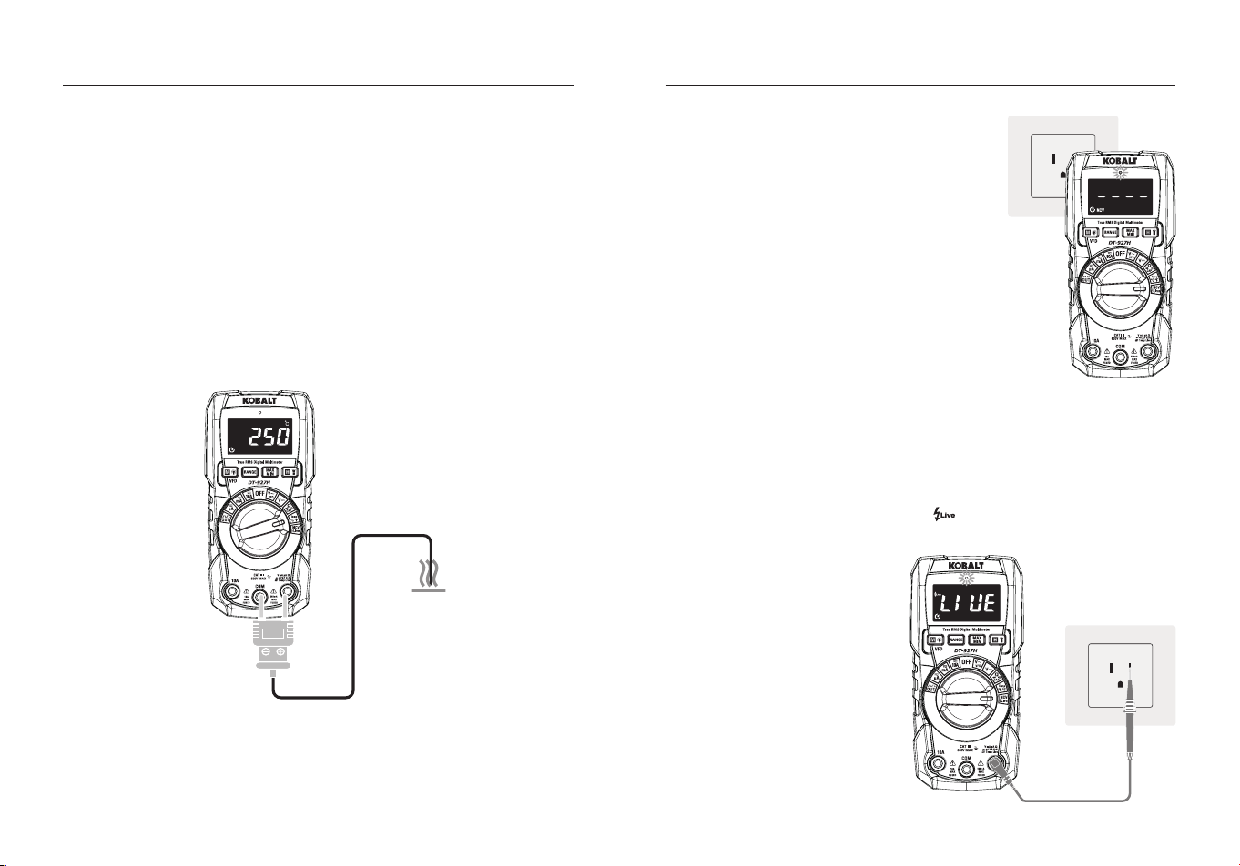
Non-Contact Voltage (NCV)
●Set the rotary function switch to the
NCV/Live
Position, LCD display “
NCV
”
Indicator and “
EF
”.
●Hold the top of the meter very close to the
voltage source as shown.
●If voltage is present, the red light will
long lighting and “
----
”will displayed, “
--
--
“ represents the strength level of the
inductive signal.
Note:
Do not touch the top of the meter
when using this function. Test on known live
circuit befor using.
Live Test
●Set the rotary function switch to the
NCV/Live
Position.
●Press the
MODE
Button to indicate “ ” on the display.
●Insert the red test lead
banana plug into the positive
Positive
Input Jack.
●The red test lead plug into
the electric socket, if it is a
re wire, the meter will alarm
the indication that the test
jack is the re wire access.
Note:
Do not touch the top
of the meter when using
this function, Test on known
live circuit befor using, Test
Voltage >90 V.
OPERATING INSTRUCTIONS
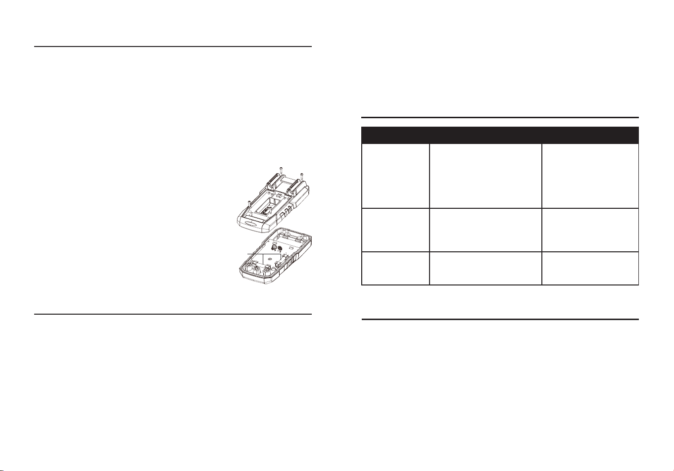
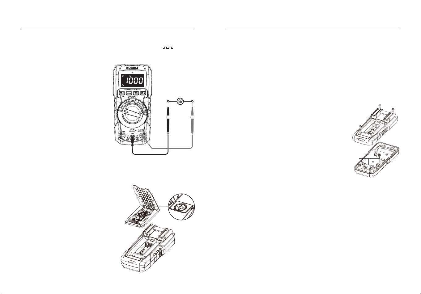
Square Wave Output
●Set the rotary function switch to the
OUT
Position.
●Insert the black test lead banana plug into the negative
COM
Input
Jack; Insert the red test lead
banana plug into the
Positive
Input Jack.
●A simple waveform generator
is needed for electronic
experiments, with continuous
square-wave signals output
between red lead and black lead.
●Press the
RANGE
Button to
Select a dierent frequency
output.
Note:
Do not enter high voltage.
OPERATING INSTRUCTIONS
Output
Battery Replacement
WARNING:
To avoid electric shock,
disconnect the test leads from any
source of voltage before removing
the battery door. Do not operate the
meter until the battery door is in place
and fastened securely.
●Lift up tilt stand to access battery
door.
●Use small coin to unlock battery
door.
●Lift up on tab below lock to remove
battery door.
●Install with two AAA 1.5 V batteries.
●Install the battery cover and lock the
battery cover.
26 27
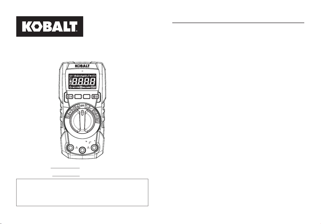
Fuse Replacement
WARNING:
To avoid electric shock, remove the test leads from the
meter before removing the fuse cover. Do not operate your meter until
the fuse door is in place and fastened securely.
●Remove the test leads from the meter and any item under test.
●Remove the battery cover and battery.
●Use a small screwdriver to remove the four screws that secure the
back cover onto the meter.
●Gently remove the back cover using caution
not to pull on the battery clip.
●Slip the battery clip though the slot on the back
cover in order to fully separate the cover from
the meter.
●Gently remove the fuse from its holder.
●Replace with a fuse of the proper size and
value (200 mA/600 V fast blow for the 200
mA range, 10 A/600 V fast blow for the 10 A
range).
●Reassemble the meter, install battery, and
tighten the screws securely on the fuse and
battery covers.
Fuse
CARE AND MAINTENANCE
●Keep the meter dry. If it gets wet, wipe it o.
●Keep the meter clean. Wipe the dirt with a soft cloth dampened with
water. Do not use chemicals, cleaning solvents, or detergents.
●Use and store the meter in normal temperatures. Temperature
extremes can shorten the life of the electronic parts and distort or
melt plastic parts.
●Handle the meter gently and carefully. Dropping it can damage the
electronic parts or the case.
●Use only fresh batteries of the recommended size and type. Batteries
are to be inserted with the correct polarity. Remove old or weak
batteries so they do not leak and damage the unit.
OPERATING INSTRUCTIONS
TROUBLESHOOTING
PROBLEM POSSIBLE CAUSE CORRECTIVE ACTION
No reading on
the LCD display
1.Batteries are weak.
2.Batteries are not
properly installed.
3.The LCD / meter is
damaged.
1.Replace batteries.
2.Install batteries
observing
polarity shown inside
battery compartment.
3.Replace meter.
All positions
measurements
have no
readings
1.Test leads are damaged.
2.The meter is damaged.
1.Replace test leads.
2.Replace meter.
Only current
measurement
has no reading
1.Fuse blew.
2.The meter is damaged.
1.Replace fuse.
2.Replace meter.
●Do not mix old and new batteries. Do not mix dierent types of
batteries such as alkaline, carbon-zinc, or rechargeable batteries.
Non-rechargeable batteries are not to be recharged.
●If the meter is to be stored for a long period of time, the batteries
should be removed to prevent damage to the unit.
WARRANTY
Three-year warranty. Incidental or consequential damages are excluded from this
warranty.
Printed in China
28 29
ARTÍCULO #5995674
MODELO #DT-927H
MULTÍMETRO CON
LINTERNA
True RMS Digital Multimeter
CAT III
600V MAX
COM
10A
500mA
MAX
FUSED
V mA µA
CAP Hz%
Temp Live
VFD
MAX
10A
FUSED
RANGE
MAX
MIN
DT-927H
KOBALT y el diseño del logotipo
son marcas comerciales o marcas
registradas de LF, LLC. Todos los
derechos reservados.
Número de serie
Fecha de compra
SG24724
ADJUNTE AQUÍ SU RECIBO
Gracias por adquirir este producto KOBALT. ¿Tiene algún
problema o le faltan piezas?
Antes de devolverlo, póngase en contacto con nosotros en el
888-356-2258
, de 8 de la mañana a 8 de la tarde, hora del este, de
lunes a domingo, o
ÍNDICE
Especicaciones del producto ..............................................................30
Contenido del paquete .........................................................................34
Información de seguridad .....................................................................38
Instrucciones de funcionamiento ..........................................................40
Cuidado y mantenimiento .....................................................................54
Resolución de problemas .....................................................................55
Garantía................................................................................................55
30 31
ESPECIFICACIONES DEL PRODUCTO
GENERAL SPECIFICATIONS
Aislamiento Clase 2, doble aislamiento
Pantalla 4000 recuentos, indicación positiva
Polaridad
Automática (sin indicación para la polaridad
positiva). Aparece el símbolo menos "-" para
la polaridad negativa
Indicación de
sobrerrango
Aparece "OL"
Factor de cresta
3 a plena escala hasta 300 V, disminuyendo
linealmente a <1,5 a 600 V
Indicación de batería
baja
“ ” aparece si la tensión de la batería cae
por debajo de la tensión de funcionamiento
Tasa de medición 3 veces por segundo, nominal
Apagado automático Aprox,15 minutes
Impedancia de entrada >10MΩ VCC y >10MΩ VCA
Respuesta de CA RMS verdadero
Ancho de banda ACV
50/60 Hz (toda la onda); 45 Hz a 1000 Hz
(onda sinusoidal)
Batería Dos pilas AAA de 1,5 V
Fusible
Rangos mA/μA 0,5 A 600 V cerámico de
disparo rápido; capacidad de ruptura: 10 kA/
600 V CA/CC Gama A: 10 A/600 V cerámica
de fusión rápida; capacidad de ruptura: 10
kA/600 V CA/CC
Entorno de
funcionamiento
32 °F a 122 °F (0 °C a 50 °C) a <70 % de
humedad relativa
Entorno de
almacenamiento
14 °F a 140 °F (-10 °C a 60 °C) a <80 % de
humedad relativa
Altitud de
funcionamiento
7000 pies (2000 m) máximo
Peso neto Aprox. 342 g (0,75 libras)
Dimensiones Aprox. 6,0x2,9x1,7 pulg. (153,6x74,5x43 mm)
Seguridad
Certicado según: CSA STD C222# 61010-
1. 61010-2-033: EN 61010-1. 61010-2-033
FUNCIÓN RANGO RESOLUCIÓN PRECISIÓN
Tensión
continua
400 mV 0,1 mV
±(1,0 %+3 dígitos)
4 V 0,001 V
40 V 0,01 V
400 V 0,1 V
600 V 1 V
Tensión alterna
(de 50 Hz a
400 Hz)
4 V 0,001 V
±(1,0 %+3 dígitos)
40 V 0,01 V
400 V 0,1 V
600 V 1 V
Todos los rangos de tensión alterna están
especicados desde el 5 % del rango hasta el 100
% del rango.
Prueba del variador de frecuencia Rango de tensión
de CA: 100 V-600 V.
Corriente
continua
400 μA 0,1 μA
±(1,0 %+3 dígitos)
4000 μA 1 μA
40 mA 0,01 mA
400 mA 0,1 mA
4 A 0,001 A
±(1,2 %+3 dígitos)
10 A 0,01 A
10 A: 30 segundos como máximo con precisión
reducida.
ESPECIFICACIONES DEL PRODUCTO
FUNCIÓN ENTRADA MÁXIMA
Tensión en CA o CC 600 V de CC/CA ecaces
mA de CA/CC
500 mA Fusible de acción rápida de
600 V
A de CA/CC 10 A 600 V fusible de acción rápida
Frecuencia, resistencia,
temperatura, capacitancia,
prueba de diodos, continuidad
600 V de CC/CA ecaces
Límites de entrada
32 33
ESPECIFICACIONES DEL PRODUCTO
FUNCIÓN RANGO RESOLUCIÓN PRECISIÓN
Tensión alterna
(de 50 Hz a 60
Hz)
400 μA 0,1 μA
±(1,2 % + 3 dígitos)
4000 μA 1 μA
40 mA 0,01 mA
400 mA 0,1 mA
4 A 0,001 A
±(1,8 % + 5 dígitos)
10 A 0,01 A
10 A: 30 s máx. con precisión reducida.
Todos los rangos de tensión alterna están
especicados desde el 5 % del rango hasta el 100
% del rango.
Resistencia
400 Ω 0,1 Ω
±(1,5 %+5 dígitos)
4 kΩ 0,001 kΩ
40 kΩ 0,01 kΩ
400 kΩ 0,1 kΩ
4 MΩ 0,001 MΩ
40 MΩ 0,01 MΩ ±(2,5 %+20 dígitos)
Capacitancia
99,99 nF 0,01 nF ±(4,5 %+20 dígitos)
999,9 nF 0,1 nF ±(4,5 %+10 dígitos)
9,999 μF 0,001 μF
±(3,5 %+5 dígitos)99,99 μF 0,01 μF
999,9 μF 0,1 μF
9,999 mF 1 μF
±(5 %+5 dígitos)
99,99 mF 10 μF
Frecuencia
(Eléctrica)
10,00-10kHz 0,01 Hz
±(1,2 % de la
lectura)
Sensibilidad: 10 V rms
Ciclo de trabajo
0,1 to 99,9% 0,1% ±(1,2 % + 2 dígitos)
Ancho de pulso: 100 μs-100 ms, Frecuencia:
5 Hz a 10 kHz.
FUNCIÓN CONDICIONES DE PRUEBA LECTURA
Diodo
Adelante CCA es aprox. 1
mA, circuito abierto tensión
MAX. 3 V
Caída de tensión
directa del diodo
Continuidad
Corriente de prueba MÁX. 1,5
mA
El zumbador emite un
sonido largo, mientras
que la resistencia es
inferior a (50 Ω)
Protección de entrada: 600 V c.c. o 600 V c.a. rms.
Nota:
La precisión se indica entre 18 y 28 °C (65 y 83 °F) y menos del
75 % de HR.
Nota:
Las especicaciones de precisión constan de dos elementos:
• (% de lectura): esta es la precisión del circuito de medición.
• (+ dígitos): esta es la precisión del convertidor analógico a digital.
FUNCIÓN RANGO RESOLUCIÓN PRECISIÓN
Frecuencia
(corriente
alterna) (rango
automático)
45 Hz to 1 kHz
±(1,0 % + 5
dígitos)
Temperatura
-20 to
1000°C
1°C ±(3% + 3°C)
-4 to 1832°F 1°F ±(3% + 5°F)
Sensor: Termopar tipo K.
Protección de entrada: 600 V c.c. o 600 V c.a.
rms.
Frecuencia de
salida de onda
cuadrada
(Rango manual)
50,100,200,300,400,500,600,
700,800,900,1000,2000,3000,
4000,5000 Hz
±(1,0 % + 5
dígitos)
ESPECIFICACIONES DEL PRODUCTO
34 35
Te
s
t
o
n
k
n
o
w
n
l
i
v
e
c
i
r
c
u
i
t
b
e
f
o
r
e
e
a
c
h
u
s
e
N
o
n
-
C
o
n
t
a
c
t
V
o
l
t
a
g
e
D
e
t
e
c
t
o
r
WARNING
100 to 600VA
C
CONTENIDO DEL PAQUETECONTENIDO DEL PAQUETE
A
B
C
E
N
L
M
K
Q
F
O
P
D
G
H
I
J
PARTE DESCRIPCIÓN
A Indicador de tensión sin contacto
B Pantalla LCD
C Botón de modo/VFD y retroiluminación
D Botón RANGE
E Botón MAX/MIN
F Botón HOLD y linterna
G Interruptor de función
H Toma de entrada de 10 A
I Toma de entrada COM
J Toma de entrada positiva
K Indicador de la linterna
L Detector de tensión sin contacto
M Soporte para colgador magnético opcional
N Almacenamiento y soporte para cables de prueba
O Cierre de la tapa de la batería
P Soporte
Q Tapa de la batería
NOTA:
Retire la película de plástico de la pantalla LCD antes de utilizarla.
PARTE DESCRIPCIÓN CANTIDAD
A Metro 1
B Conductores de prueba 1
C Sonda de temperatura tipo K 1
D Batería de 1.5 voltios 2
A B C D
36 37
Símbolos
PART DESCRIPTION
Peligro potencial. Indica que el usuario debe consultar el
manual para obtener información de seguridad importante.
Indica que puede haber tensiones peligrosas.
El equipo está protegido por un aislamiento doble o
reforzado.
Indica que el (los) borne(s) así marcado(s) no debe(n)
conectarse a un circuito en el que la tensión con respecto
a la tierra de seguridad del medidor supere la tensión de
seguridad máxima del medidor.
Salida de onda cuadrada
Prueba de línea viva
Tensión o corriente alterna
Tensión o corriente continua
Signo menos
Batería baja
Apagado automático
Mega (10
6
)
kilo (10
3
)
Ohmios
Hertzios (frecuencia)
Ciclo de trabajo
milli (10
-3
)
Micro (valor x 10
-6
)
Voltios
Amperios
Nano (valor x 10
-9
)
Faradios
Prueba de diodos
Continuidad
Grado Celsius
Grado Fahrenheit
Lectura de medición
Tensión sin contacto
Prueba del variador de frecuencia de tensión alterna
Autorretención
Máximo
Mínimo
Rango automático
Cables de prueba
ADVERTENCIA:
El funcionamiento está limitado a aplicaciones
CAT II cuando se retiran las puntas aisladas de una o ambas puntas
de prueba. Consulte la sección "Límites de entrada" de este manual
para conocer los valores máximos de tensión.
Punta aislada puesta
Punta aislada quitada
CATEGORÍA
BREVE
DESCRIPCIÓN
APLICACIONES TÍPICAS
CAT II
Receptáculos
monofásicos
y cargas
conectadas.
-Electrodomésticos, herramientas
eléctricas.
-Enchufes a más de 10 m (30 pies)
de una fuente CAT III.
-Enchufes a más de 20 m (60 pies)
de una fuente CAT IV.
CAT III
Circuitos
trifásicos y
circuitos de
iluminación
monofásicos
en edicios
comerciales.
-Equipos en instalaciones jas como
motores trifásicos, aparamenta y
cuadros de distribución - Circuitos de
alumbrado en edicios comerciales.
-Líneas de alimentación en plantas
industriales.
-Cualquier dispositivo o circuito
derivado que es té cerca de una
fuente CAT III.
Clasicaciones de las categorías de seguridad
La clasificación de la categoría de medición (CAT) y la clasificación
de la tensión vienen determinadas por la combinación del medidor,las
puntas de prueba y cualquier accesorio conectado al medidor y a las
puntas de prueba. La clasicación de la combinación es la MÁS BAJA
de cualquier componente individual.
38 39
INFORMACIÓN DE SEGURIDAD
ADVERTENCIAS
●Lea y comprenda todo este manual antes de utilizar este producto.
●Antes de cambiar de función utilizando el conmutador selector,
desconecte siempre los cables de prueba del circuito sometido a
prueba.
●Asegúrese de que los cables de prueba están completamente
asentados en las tomas de entrada y mantenga los dedos alejados
de las puntas de las sondas metálicas cuando realice mediciones.
●Utilice solo cables de prueba certicados con la clasicación de
categoría de seguridad adecuada.
●Verique el funcionamiento antes de utilizar el medidor midiendo una
tensión viva conocida.
●Tenga precaución en circuitos con tensión. Las tensiones superiores
a 30 V de CA rms, 42 V de CA pico o 60 V de CC suponen un riesgo
de descarga eléctrica.
●Cumpla con todos los códigos de seguridad aplicables. Utilice equipo
de protección personal homologado cuando trabaje cerca de circuitos
eléctricos en tensión, especialmente en lo que se reere al potencial
de arco eléctrico.
●No lo utilice si el medidor o los cables de prueba parecen estar
dañados.
●No utilice el medidor ni cerca de vapores, polvo o gases explosivos.
●No utilice el medidor en entornos húmedos o mojados ni durante
tormentas eléctricas.
●No utilice el medidor si funciona incorrectamente. La protección
puede verse comprometida.
●No utilice el medidor mientras esté encendido el aviso de batería
baja. Sustituya las pilas inmediatamente.
●No aplique voltaje o corriente que exceda los límites de entrada
nominal máxima del medidor.
"Este aparato cumple con la parte 15 de las normas de la FCC. Su
funcionamiento está sujeto a las dos condiciones siguientes: (1) Este
dispositivo no puede causar interferencias perjudiciales, y (2) este
dispositivo debe aceptar cualquier interferencia recibida, incluidas las
interferencias que puedan causar un funcionamiento no deseado".
Lowe's Home Centers LLC 1000 Lowe's Blvd.
Mooresville, NC 28117
1-888-3KOBALT (1-888-356-2258)
Este equipo ha sido probado y se ha determinado que cumple con
los límites para un dispositivo digital de Clase B, de conformidad con
la parte 15 de las normas de la FCC. Estos límites están diseñados
para proporcionar una protección razonable contra interferencias
perjudiciales en una instalación residencial. Este equipo genera,
utiliza y puede irradiar energía de radiofrecuencia y, si no se instala y
utiliza de acuerdo con las instrucciones, puede causar interferencias
perjudiciales en las comunicaciones por radio. Sin embargo, no existe
ninguna garantía de que no se produzcan interferencias en una
instalación concreta. Si este equipo causa interferencias perjudiciales
en la recepción de radio o televisión, lo que puede determinarse
apagando y encendiendo el equipo, se recomienda al usuario que
intente corregir las interferencias mediante una o varias de las
siguientes medidas:
1.Reorientar o reubicar la antena receptora.
2.Aumentar la separación entre el equipo y el receptor.
-Conecte el equipo a una toma de corriente de un circuito distinto al
que está conectado el receptor.
-Consulte al distribuidor o a un técnico experto en radio/TV para
obtener ayuda.
"
PRECAUCIÓN
: Los cambios o modicaciones no aprobados
expresamente por la parte responsable del cumplimiento podrían
anular la autoridad del usuario para utilizar el equipo".
Se advierte a los usuarios de este producto que no realicen
modicaciones ni cambios. Hacerlo puede anular la conformidad de este
producto con las leyes y requisitos reglamentarios aplicables y puede
dar lugar a la pérdida de la autoridad del usuario para utilizar el equipo.
CONFORMIDAD DEL PRODUCTO

40 41
INSTRUCCIONES DE FUNCIONAMIENTO
Autoajuste/Selección manual de rangos
●Para encender el medidor, gire el selector de funciones desde la
posición de apagado hasta cualquier posición de medición. Para
APAGAR el medidor gire el interruptor selector de función hasta el
ajuste de apagado.
●Cuando el medidor se enciende por primera vez, entra
automáticamente en rango automático.
●Esto selecciona automáticamente el mejor rango para las mediciones
que se están realizando y es generalmente el mejor modo para la
mayoría de las mediciones.
●Para situaciones de medición que requieran que se seleccione
manualmente un rango, realice lo siguiente:
1. Pulse el botón RANGO, el indicador "AUTOMÁTICO" de la pantalla
se apagará.
2. Pulse el botón RANGO para recorrer los rangos disponibles hasta
seleccionar el rango que desee.
3. Para salir del modo de alcance manual y volver al modo de
alcance automático, mantenga pulsado el botón RANGO durante 2
segundos.
Nota:
La escala manual no se aplica a las funciones de Capacitancia y
Frecuencia.
MÁX./MÍN.
Nota:
Cuando utilice la función MÁX./MÍN. en el modo de escala
automática, el medidor se "bloqueará" en la escala que se muestra en
la pantalla LCD cuando se activa MÁX./MÍN. Si una lectura MÁX./MÍN.
supera esa escala, se mostrará un "OL". Seleccione la escala deseada
antes de entrar en el modo MÁX./MÍN.
●Pulse el Botón
MÁX./MÍN
. para activar el modo de registro MÁX./
MÍN., aparecerá el icono de pantalla "
MÁX.
", el medidor mostrará
y mantendrá la lectura máxima y se actualizará sólo cuando se
produzca un nuevo "máx.".
●Pulse de nuevo el botón
MÁX./MÍN.
y aparecerá el icono de pantalla
"
MÍN.
", el medidor mostrará y retendrá la lectura mínima y se
actualizará sólo cuando se produzca un nuevo "mín.".
●Para salir del modo MÁX./MÍN. pulse y mantenga pulsado el Botón
MÁX./MÍN. durante 2 segundos.
INSTRUCCIONES DE FUNCIONAMIENTO
Controles retroiluminados
Todos los controles están retroiluminados para una mayor visibilidad
con poca luz.
MODO/VFD/Luz de fondo
●Pulsando el Botón MODO es posible la selección de las funciones de
medida dobles que están presentes en la pantalla, en particular esta
tecla está activa en la Posición V Ω CAP para seleccionar entre
Prueba de Resistencia, Prueba de Diodo, Prueba de Continuidad,
Prueba de Capacitancia y Prueba VFD y en la posición Corriente
para seleccionar entre medidas de corriente AC o DC.
●Pulse el botón
MODO
durante >1 segundo para activar o desactivar
la función de retroiluminación (retroiluminación del interruptor
giratorio), la retroiluminación se apagará automáticamente tras 3
minutos de inactividad.
MANTENER/linterna
●La función de retención congela la lectura en la pantalla, pulse el
Botón MANTENER momentáneamente para activar o salir de la
función MANTENER.
●Pulse el botón MANTENER durante >1 segundo para activar o
desactivar la función Linterna.
Apagado automático:
●La función de apagado automático apagará el medidor transcurridos
15 minutos.
●Para desactivar la función de apagado automático, mantenga
pulsado el botón Modo y encienda el medidor.
Nota:
Los datos anteriores son solo de referencia.
42 43
INSTRUCCIONES DE FUNCIONAMIENTO
Medición de la tensión continua
PRECAUCIÓN:
No mida tensiones continuas si se está encendiendo
o apagando un motor del circuito. Pueden producirse grandes subidas
de tensión que pueden dañar el medidor.
●Coloque el interruptor de función giratorio en la Posición
VDC
.
●Inserte el conector banana del cable de prueba negro en la toma
de entrada
COM
negativa; Inserte el conector banana del cable de
prueba rojo en la toma de entrada
positiva
.
●Toque con la punta de la sonda de prueba negra el lado negativo
del circuito; Toque con la punta de la sonda de prueba roja el lado
positivo del circuito.
●Lea la tensión en la pantalla LCD.
Medición de la tensión alterna (frecuencia, ciclo de trabajo)
ADVERTENCIA:
Riesgo de electrocución. Es posible que las puntas
de las sondas no sean lo sucientemente largas para entrar en
contacto con las partes activas del interior de algunas tomas de 240 V
para electrodomésticos porque los contactos están empotrados en la
profundidad de las tomas. Como resultado, la lectura puede mostrar 0
voltios cuando en realidad la toma tiene tensión. Asegúrese de que las
puntas de las sondas están tocando los contactos metálicos del interior
de la toma antes de suponer que no hay tensión.
PRECAUCIÓN:
No mida tensiones de CA si se está encendiendo o
apagando un motor del circuito. Pueden producirse grandes subidas
de tensión que pueden dañar el medidor.
●Coloque el interruptor de función giratorio en la Posición
VAC/VFD
.
●Inserte la clavija banana del cable de prueba negro en la toma de
entrada
COM
negativa; Inserte la clavija banana del cable de prueba
rojo en la toma de entrada
positiva
.
●Toque con la punta de la sonda de prueba negra el lado negativo
del circuito; Toque con la punta de la sonda de prueba roja el lado
"caliente" del circuito.
●Lea la tensión en la pantalla LCD.
●Pulse el botón
MODO
para
indicar "
Hz
".
●Pulse de nuevo el Botón
MODO
para indicar "
%
".
●Pulse de nuevo el Botón
MODO
para indicar
VFD
.
●Lea la tensión de CA, Hz, % y
tensión VFD en la pantalla.
INSTRUCCIONES DE FUNCIONAMIENTO
44 45
Medición de la corriente continua
PRECAUCIÓN:
No realice mediciones de corriente de 10 A durante
más de 30 segundos. Si supera los 30 segundos puede dañar el
medidor o los cables de prueba. Cuando mida corrientes superiores a
4 A, se recomienda un tiempo de medición de 30 segundos seguido de
10 minutos de tiempo de recuperación.
●Inserte el conector banana del cable de prueba negro en la Toma de
Entrada
COM
negativa.
●Para mediciones de corriente de hasta
4000 μA CC
, coloque el
conmutador de funciones en la posición
μA
e inserte el conector
banana rojo del cable de prueba en la toma de entrada
μA/mA
.
●Para mediciones de corriente de hasta
400 mA CC
, coloque el
conmutador de funciones en la Posición
mA
e inserte el conector
banana rojo del cable de prueba en la Toma de Entrada μA/mA.
●Para mediciones de corriente de hasta
10 A CC
, coloque el
conmutador de funciones en la posición
10 A
e inserte la clavija
banana roja del cable de prueba en la toma de entrada de 10 A.
●Pulse el botón
MODO
para indicar " " en la pantalla.
●Desconecte la alimentación del circuito bajo prueba, luego abra el
circuito en el punto donde desea medir la corriente.
●Toque con la punta de la
sonda de prueba negra el lado
negativo del circuito; Toque con
la punta de la sonda de prueba
roja el lado positivo del circuito.
●Aplique corriente al circuito.
●Lea la corriente en la pantalla.
INSTRUCCIONES DE FUNCIONAMIENTO
Medición de la corriente alterna (frecuencia, ciclo de trabajo)
PRECAUCIÓN:
No realice mediciones de corriente de 10 A durante
más de 30 segundos. Exceder los 30 segundos puede causar daños
en el medidor o en los cables de prueba. Cuando mida corrientes
superiores a 4 A, se recomienda un tiempo de medición de 30
segundos seguido de 10 minutos de tiempo de recuperación.
●Inserte la clavija banana del cable de prueba negro en la Toma de
Entrada
COM
negativa.
●Para mediciones de corriente de hasta
4000 μA CA
, coloque el
conmutador de funciones en la posición
μA
e inserte el conector
banana rojo del cable de prueba en la toma de entrada
μA/mA
.
●Para mediciones de corriente de hasta
400 mA CA
, coloque el
conmutador de funciones en la posición
mA
e inserte el conector
banana rojo del cable de prueba en la toma de entrada de
μA/mA
.
●Para mediciones de corriente de hasta
10 A CA
, coloque el
conmutador de funciones en la posición
10 A
e inserte la clavija
banana roja del cable de prueba en la toma de entrada de
10 A
.
●Pulse el Botón
MODO
para indicar " " en la pantalla.
●Pulse el Botón
MODO
para indicar "
Hz
".
●Pulse de nuevo el Botón
MODO
para indicar "
%
".
●Desconecte la alimentación del
circuito bajo prueba, luego abra
el circuito en el punto donde
desea medir la corriente.
●Toque con la punta de la sonda
de prueba negra el lado neutro
del circuito; Toque con la punta
de la sonda de prueba roja el
lado "caliente" del circuito.
●Aplique corriente al circuito.
●Lea la corriente en la pantalla.
INSTRUCCIONES DE FUNCIONAMIENTO
46 47
Medición de la resistencia
ADVERTENCIA:
Para evitar descargas eléctricas, desconecte
la alimentación de la unidad bajo prueba y descargue todos los
condensadores antes de realizar cualquier medición de resistencia.
Retire las pilas y desenchufe los cables de alimentación.
●Coloque el interruptor de función giratorio en la posición Ω CAP.
●Inserte el conector banana del cable de prueba negro en la toma
de entrada
COM
negativa; Inserte el conector banana del cable de
prueba rojo en la toma de entrada positiva.
●Pulse el botón
MODO
para indicar "
Ω
" en la pantalla.
●Toque con las puntas de la sonda de prueba el circuito o la pieza bajo
prueba, es mejor desconectar un lado de la pieza bajo prueba para
que el resto del circuito no interera con la lectura de la resistencia.
●Lea la resistencia en la pantalla.
INSTRUCCIONES DE FUNCIONAMIENTO
Comprobación de la continuidad
ADVERTENCIA:
Para evitar descargas eléctricas, nunca mida la
continuidad en circuitos o cables que tengan tensión.
●Coloque el interruptor de función giratorio en la posición Ω CAP.
●Inserte el conector banana del cable de prueba negro en la toma
de entrada
COM
negativa; Inserte el conector banana del cable de
prueba rojo en la toma de entrada
positiva
.
●Pulse el botón
MODO
para indicar " " y "
Ω
” en la pantalla.
●Toque con las puntas de las sondas de prueba el circuito o cable que
desee comprobar.
●Si la resistencia es inferior a 50 Ω aproximadamente, la señal
acústica sonará; si el circuito está abierto, la pantalla indicará “
OL
”.
INSTRUCCIONES DE FUNCIONAMIENTO
48 49
Prueba de diodo
●Coloque el interruptor de función giratorio en la Posición Ω CAP.
●Inserte el conector banana del cable de prueba negro en la toma
de entrada
COM
negativa; inserte el conector banana del cable de
prueba rojo en la toma de entrada
positiva
.
●Pulse el botón
MODO
para indicar " " y "
V" en la pantalla.
●Toque con las puntas de prueba el diodo bajo prueba.
●La tensión directa indicará normalmente de 0,400 a 0,700 V; la
tensión inversa indicará "
OL
"; los dispositivos en cortocircuito
indicarán cerca de 0 V y un dispositivo abierto indicará "
OL
" en
ambas polaridades.
INSTRUCCIONES DE FUNCIONAMIENTO
Medición de la capacitancia
ADVERTENCIA:
Para evitar descargas eléctricas, desconecte
la alimentación de la unidad bajo prueba y descargue todos los
condensadores antes de realizar cualquier medición de capacitancia.
Retire las pilas y desenchufe los cables de alimentación.
●Coloque el interruptor de función giratorio en la posición Ω CAP.
●Inserte el conector banana del cable de prueba negro en la toma
de entrada
COM
negativa; Inserte el conector banana del cable de
prueba rojo en la toma de entrada
positiva
.
●Pulse el botón
MODO
para indicar "
nF
" en la pantalla.
●Toque con los cables de prueba el condensador a probar.
●La prueba puede tardar hasta 30s o más para que los condensadores
grandes se carguen, espere hasta que las lecturas se asienten antes
de nalizar la prueba.
●Lea el valor de la capacitancia en la pantalla.
INSTRUCCIONES DE FUNCIONAMIENTO
50 51
Medición de la temperatura
ADVERTENCIA:
No toque la sonda de temperatura con circuitos bajo
tensión.
●Coloque el interruptor de función en la posición
Temp
.
●Pulse el botón
MODO
para indicar
°C
o
°F.
●Conecte la sonda de temperatura al adaptador de enchufe banana,
observe las marcas - y + del adaptador.
●Conecte el adaptador al medidor, asegurándose de que el lado -
entra en la toma de entrada
COM
y el lado + en la toma de entrada
positiva
.
●Toque con la punta de la sonda de temperatura el objeto que va a
medir.
●Lea la temperatura en la pantalla LCD.
INSTRUCCIONES DE FUNCIONAMIENTO
Tensión sin contacto (NCV)
●Coloque el conmutador de funciones
giratorio en la posición NCV/Live, en
la pantalla LCD aparecerá el indicador
"
NCV
" y "
en vivo
".
●Mantenga la parte superior del medidor
muy cerca de la fuente de tensión como
se muestra.
●Si hay tensión, la luz roja se encenderá
durante mucho tiempo y aparecerá "
----
"en
la pantalla, "
----
" representa el nivel de
intensidad de la señal inductiva.
Nota:
No toque la parte superior del
medidor cuando utilice esta función. Realice
la prueba en un circuito vivo conocido antes
de utilizar.
Prueba en vivo
●Coloque el conmutador rotativo de funciones en la posición
NCV/en
vivo
.
●Pulse el botón
MODO
para indicar " " en la pantalla.
●Inserte la clavija banana del cable de prueba rojo en la toma de
entrada
positiva
.
●Inserte el conector del cable
de prueba rojo en la toma de
enchufe, si se trata de un cable
de fuego, el medidor emitirá
una alarma que indicará que
la clavija de prueba es el cable
de fuego de acceso.
Nota:
No toque la parte superior
del medidor cuando utilice esta
función, pruebe en un circuito
vivo conocido antes de utilizar,
Tensión de prueba >90 V.
INSTRUCCIONES DE FUNCIONAMIENTO
52 53
Salida de onda cuadrada
●Coloque el interruptor de función giratorio en la posición
FUERA.
●Inserte el conector banana del cable de prueba negro en la toma de
entrada
COM
negativa; Inserte
el conector banana del cable de
prueba rojo en la toma de entrada
positiva
.
●Para los experimentos
electrónicos se necesita un
generador de ondas sencillo, con
salida de señales continuas de
onda cuadrada
●entre el cable rojo y el cable
negro.
●Pulse el botón
RANGO
para
seleccionar una salida de
frecuencia diferente.
Nota:
No entre en alta tensión.
Output
Sustitución de la batería
ADVERTENCIA:
Para evitar descargas eléctricas, desconecte
los cables de prueba de cualquier
fuente de tensión antes de retirar la
tapa del portapilas. No haga funcionar
el medidor hasta que la tapa del
portapilas esté colocada y bien sujeta.
●Levante el soporte inclinable para
acceder a la tapa de la batería.
●Utilice una moneda pequeña para
desbloquear la tapa de las pilas.
●Levante la lengüeta situada debajo
del cierre para extraer la tapa de las
pilas.
●Instálela con dos pilas AAA de 1,5 V.
●Instale la tapa de las pilas y bloquee
la tapa.
INSTRUCCIONES DE FUNCIONAMIENTO
Sustitución de fusibles
ADVERTENCIA:
Para evitar descargas eléctricas, retire los cables de
prueba del medidor antes de quitar la tapa de fusibles. No active su
medidor hasta que la tapa de fusibles esté colocada y bien sujeta.
●Retire los cables de prueba del medidor y de cualquier elemento
sometido a prueba.
●Retire la tapa de la batería y la pila.
●Utilice un destornillador pequeño para retirar los cuatro tornillos que
jan la tapa posterior al medidor.
●Retire suavemente la tapa posterior con
cuidado de no arrastrar el clip de la pila.
●Deslice el clip de la pila por la ranura de la
tapa trasera para separar completamente la
tapa del medidor.
●Retire con cuidado el fusible de su soporte.
●Sustitúyalo por un fusible del tamaño y valor
adecuados (200 mA/600 V de fusión rápida
para el rango de 200 mA, 10 A/600 V de
fusión rápida para el rango de 10 A).
●Vuelva a montar el medidor, instale la batería
y apriete bien los tornillos de las tapas del
fusible y de la batería.
Fuse
INSTRUCCIONES DE FUNCIONAMIENTO

54 55
CUIDADO Y MANTENIMIENTO
●Mantenga el medidor seco. Si se moja, límpielo con un paño.
●Mantenga limpio el medidor. Limpie la suciedad con un paño suave
humedecido con agua. No utilice productos químicos, disolventes de
limpieza ni detergentes.
●Utilice y guarde el medidor a temperaturas normales. Las
temperaturas extremas pueden acortar la vida útil de las piezas
electrónicas y deformar o fundir las piezas de plástico.
●Manipule el medidor con suavidad y cuidado. Dejarlo caer puede
dañar las piezas electrónicas o la carcasa.
●Utilice solo pilas nuevas del tamaño y tipo recomendados. Las pilas
deben colocarse con la polaridad correcta. Retire las pilas viejas o
débiles para que no se derramen y dañen la unidad.
●No mezcle pilas viejas y nuevas. No mezcle diferentes tipos de pilas
como las alcalinas, las de carbono-zinc o las recargables. Las pilas
no recargables no deben recargarse.
●Si se va a almacenar el medidor durante un largo periodo de tiempo,
se deben extraer las pilas para evitar daños en el aparato.
RESOLUCIÓN DE PROBLEMAS
PROBLEMA POSIBLE CAUSA ACCIÓN CORRECTIVA
No hay lectura
en la pantalla
LCD
1. Las pilas están
descargadas.
2.Las pilas no
están instaladas
correctamente.
3.La pantalla LCD / el
medidor está dañado.
1. Cambie las pilas.
2. Instale las pilas
observando la polaridad
indicada en el interior del
compartimento de las
pilas.
3.Vuelva a colocar el
medidor.
Todas las
mediciones de
posición no
tienen lectura
1. Los cables de prueba
están dañados.
2. El medidor está
dañado.
1. Sustituya los cables de
prueba.
2. Sustituya el medidor.
Solo la
medición actual
no tiene lectura
1.Se ha fundido el
fusible.
2.El medidor está
dañado.
1. Sustituya el fusible. 2.
Sustituya el contador.
GARANTÍA
Tres años de garantía. Quedan excluidos de esta garantía los daños incidentales
o consecuentes.
Impreso en China