
ITEM #5996929
MODEL #DT-9181H
400A AC/DC TRMS
CLAMP METER
Español p.26
KOBALT and logo design are
trademarks or registered trademarks
of LF, LLC. All rights reserved.
Serial Number
Purchase Date
SG24726
Thank you for purchasing this KOBALT product.
Questions problems or missing parts?
Before returning. contact us on:
888-356-2258
, 8 a.m. - 8 p.m., EST, Monday - Sunday.
or
ATTACH YOUR RECEIPT HERE
2 3
TABLE OF CONTENTS PRODUCT SPECIFICATIONS
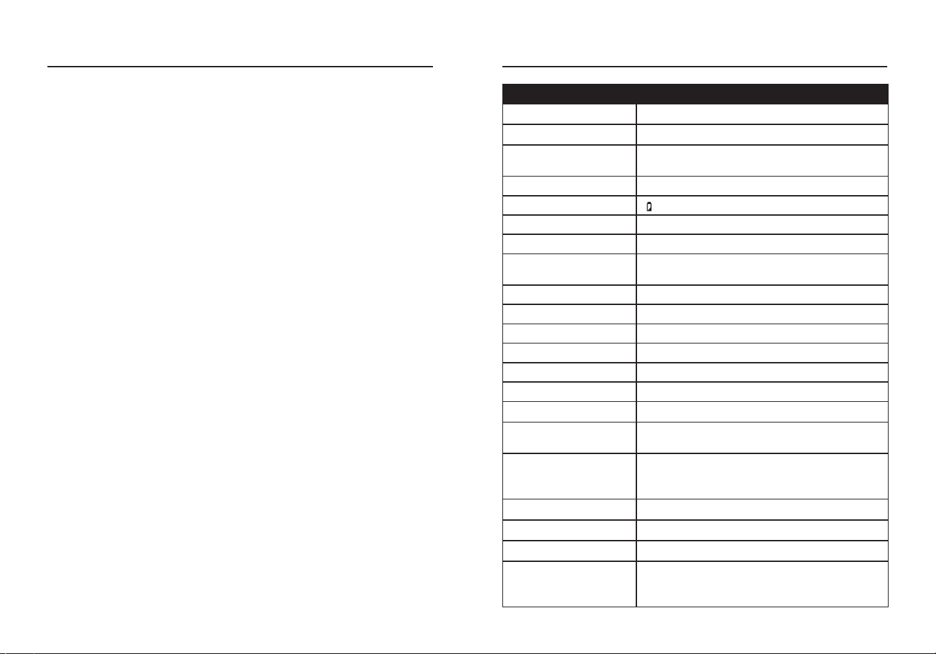
GENERAL SPECIFICATIONS
Clamp Size Opening 1.18 in. (30 mm) approx.
Over Voltage CAT III 600 V
Diode Test
Test current 1 mA max; open circuit voltage
of 2 V typical
Continuity Test Audible signal if the resistance is <50 Ω
Low Battery Indication “ ” is displayed
Display 4000 Count negative display
Over Range Indication “OL” is displayed
Polarity
Minus symbol “-“ is displayed for negative
polarity
Measurement Rate 3 readings per second, nominal
Auto Power O Approx.15 minutes
Input Impedance Approx.10 MΩ (VDC and VAC)
AC Response True RMS Responding
AC Voltage Bandwidth 50 to 1 kHz
AC Current Bandwidth 50 to 60 Hz
Batteries Three AAA 1.5 V batteries
Operating Environment
41 to 104°F (5 to 40°C) at <75% relative
humidity
Storage Environment
14 to 122°F(-10 to 50°C) at Max 80% up to
87°F (31°C), decreasing linearly to 50% at
104°F(40°C)
Operating Altitude 7000 ft (2000 m) maximum
Dimensions Approx.8.8x3.0x1.55 in. (224x76x39.5 mm)
Net Weight Approx.0.59 lbs. (267 g)
Safety
Conforms to: UL STD 61010-1.61010-2.032
Certied to: CSA STD C222# 61010-1.
61010-2-032: EN 61010-1. 61010-2-032
Product Specications ...........................................................................3
Package Contents .................................................................................6
Safety Information ................................................................................10
Operating Instructions ..........................................................................12
Care and Maintenance .........................................................................24
Troubleshooting ....................................................................................25
Warranty ...............................................................................................25
4 5
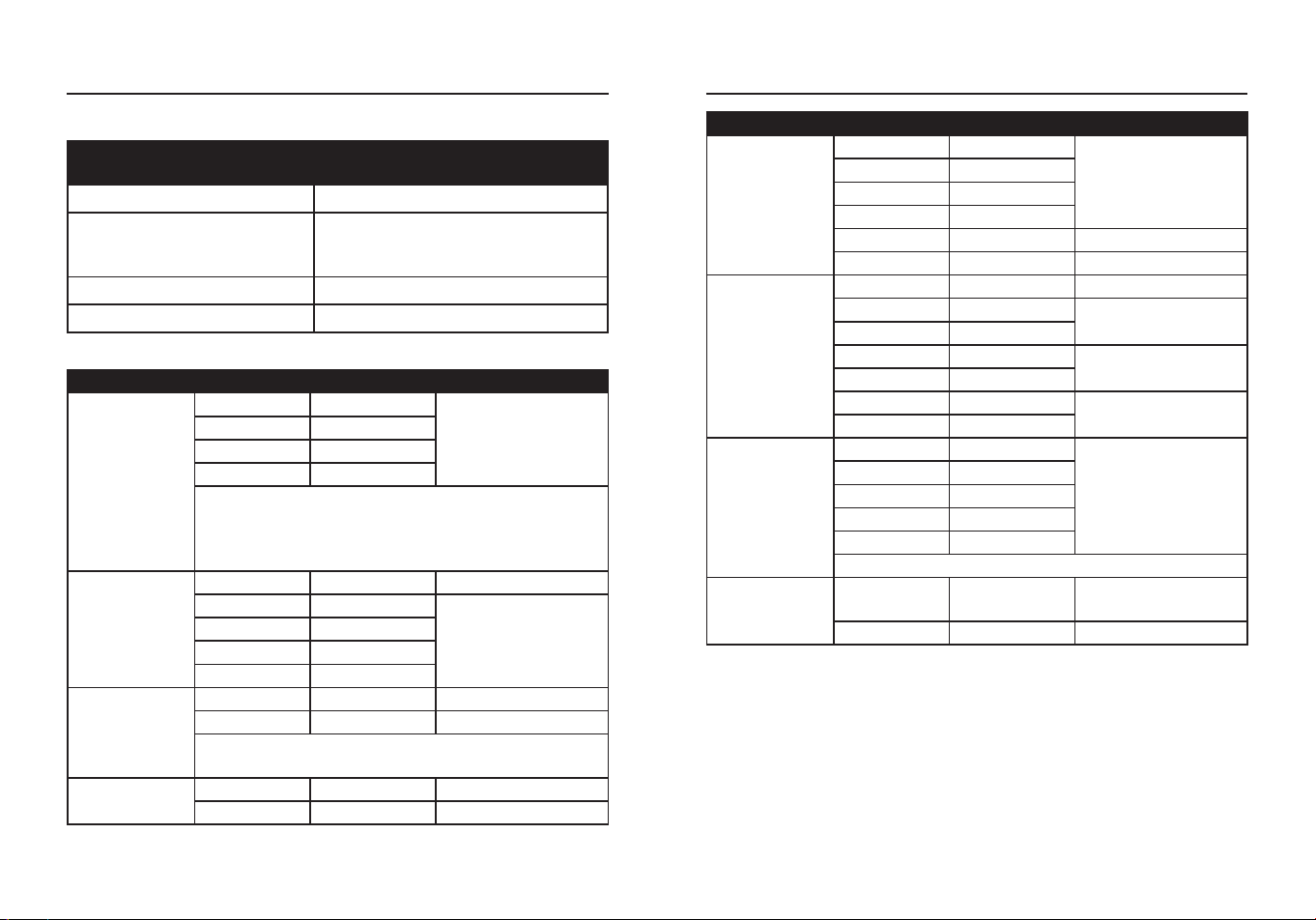
FUNCTION
MAXIMUM INPUT VOLTAGE/
CURRENT
Voltage AC or DC 600 V AC/DC
Resistance, Continuity,
Diode Test, Capacitance,
Temperature
250 V AC/DC
Current AC or DC 400 A
Frequency 600 V AC/DC
Input Limits
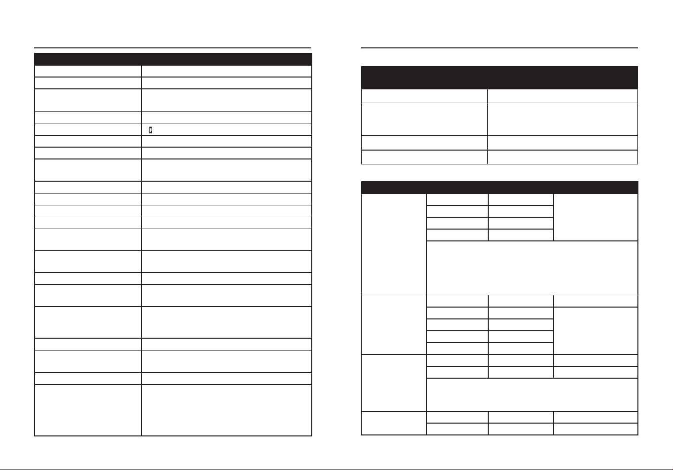
Specications
FUNCTION RANGE RESOLUTION ACCURACY
AC Voltage
50 to 1 kHz
4 V 0.001 V
±(1.2%+5 digits)
40 V 0.01 V
400 V 0.1 V
600 V 1 V
All AC voltage ranges are specied from 5% of range
to 100% of range.
AC Voltage Bandwidth: 50 to 60 Hz (All Wave);
50 to 1 kHz (Sine Wave).
DC Voltage
400 mV 0.1 mV ±(0.5%+5 digits)
4 V 0.001 V
±(0.5%+8 digits)
40 V 0.01 V
400 V 0.1 V
600 V 1 V
AC Current
50 to 60 Hz
40 A 0.01 A ±(2.5%+10 digits)
400 A 0.1 A ±(2.8%+8 digits)
All AC Current ranges are specied from 5% of
range to 100% of range.
DC Current
40 A 0.01 A ±(2.5%+8 digits)
400 A 0.1 A ±(2.8%+8 digits)
FUNCTION RANGE RESOLUTION ACCURACY
Resistance
400 Ω 0.1 Ω
±(1.2%+5 digits)
4 kΩ 0.001 kΩ
40 kΩ 0.01 kΩ
400 kΩ 0.1 kΩ
4 MΩ 0.001 MΩ ±(2.0%+5 digits)
40 MΩ 0.01 MΩ ±(3.0%+8 digits)
Capacitance
4 nF 0.001 nF ±(3.5%+60 digits)
40 nF 0.01 nF
±(3.0%+10 digits)
400 nF 0.1 nF
4 µF 0.001 µF
±(3.8%+5 digits)
40 µF 0.01 µF
400 µF 0.1 µF
±(3.5%+5 digits)
4 mF 0.001 mF
Frequency
4 Hz 0.001 Hz
±(1.2%+5 digits)
40 Hz 0.01 Hz
400 Hz 0.1 Hz
4 kHz 0.001 kHz
10 kHz 0.01 kHz
Sensitivity: >15 V RMS.
Temperature
-18 to 1000
°C
1 °C ±(1.5%+5 °C)
0 to 1832 °F 1 °F ±(1.5%+9 °F)
Accuracy is stated at 18 to 28 °C (65 to 83 °F) and less than 75% RH.
Accuracy specications consist of two elements:
(% reading)- This is the accuracy of the measurement circuit.
(+ digits)- This is the accuracy of the analog to digital converter.
PRODUCT SPECIFICATIONSPRODUCT SPECIFICATIONS
6 7
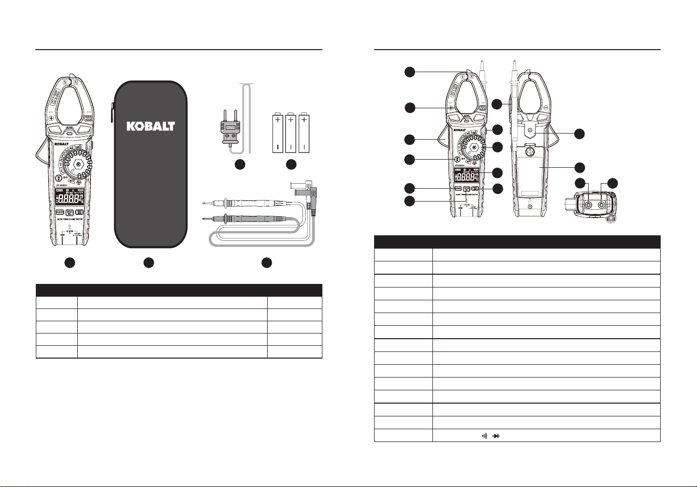
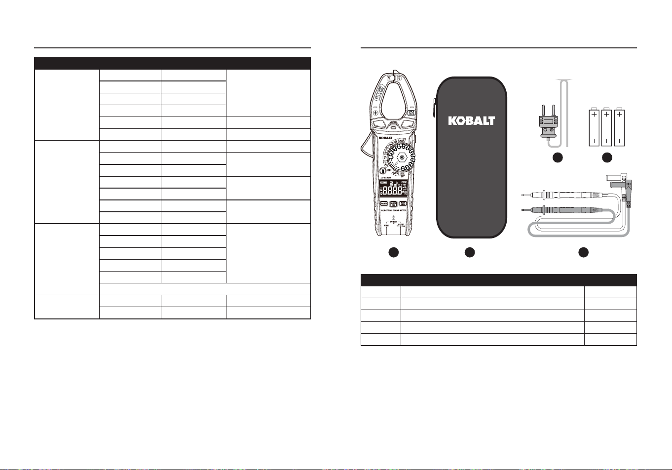
PACKAGE CONTENTS
PART DESCRIPTION QUANTITY
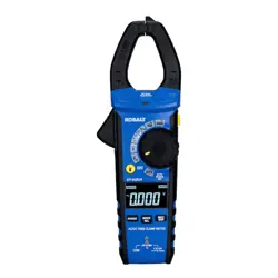
A Clamp meter 1
B Carrying case 1
C Test Leads 1
D Type K temperature probe 1
E 1.5-volt battery 3
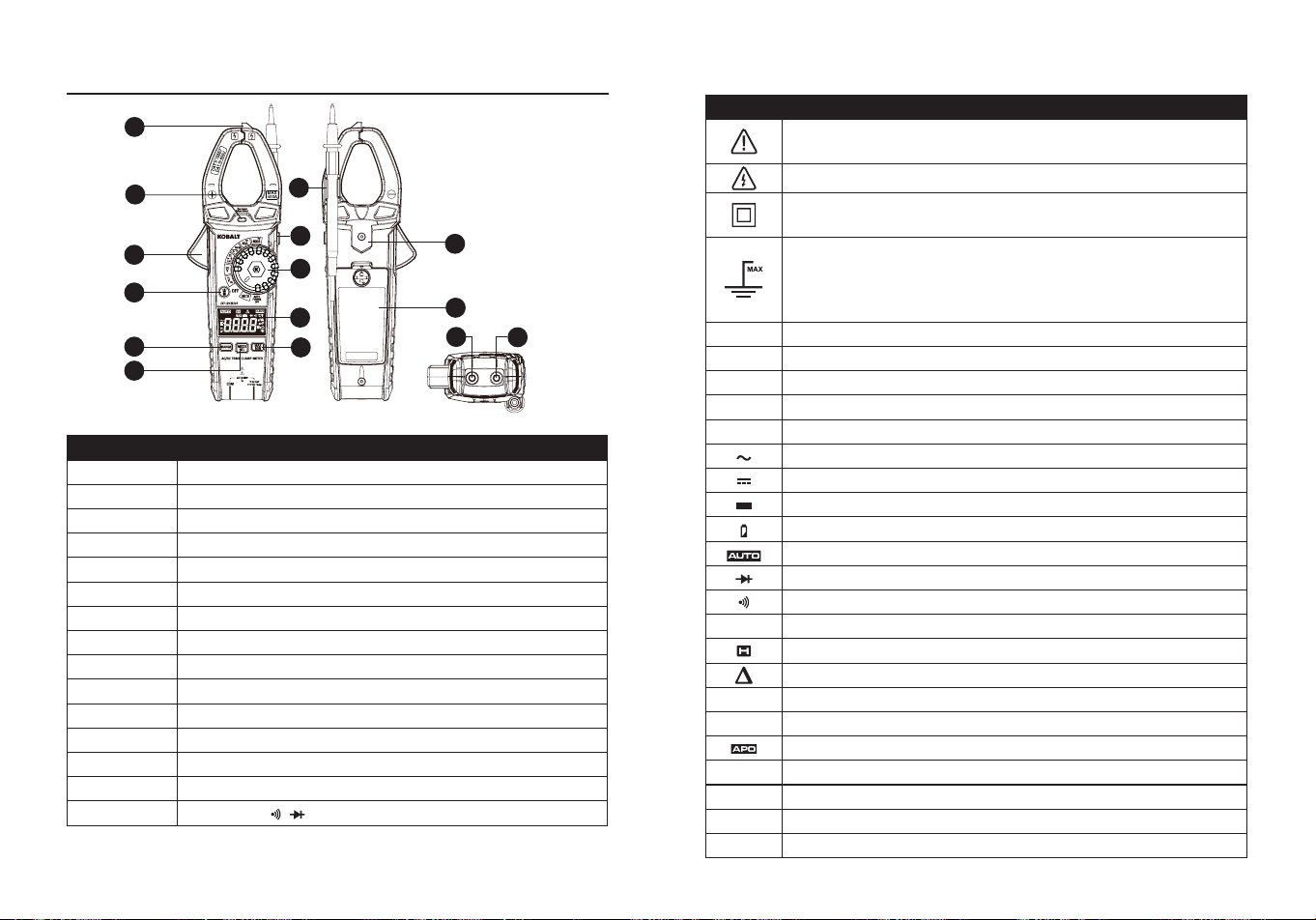
PACKAGE CONTENTS
PART DESCRIPTION
A Non-Contact voltage detector
B Non-Contact voltage indicator
C Clamp trigger
D Test lead holder
E HOLD button
F Rotary function switch
G Flashlight button
H LCD display
I RANGE button
J MAX/MIN button
K MODE and Relative Button
L Magnetic strap insert
M Battery cover
N COM input jack
O V, Ω, CAP, , , Hz, Temp input jack
NOTE
: Remove the plastic lm on the LCD display before use.
A
B
C
G
I
K
F
M
N
L
O
E
D
H
J
BA C
D E
8 9
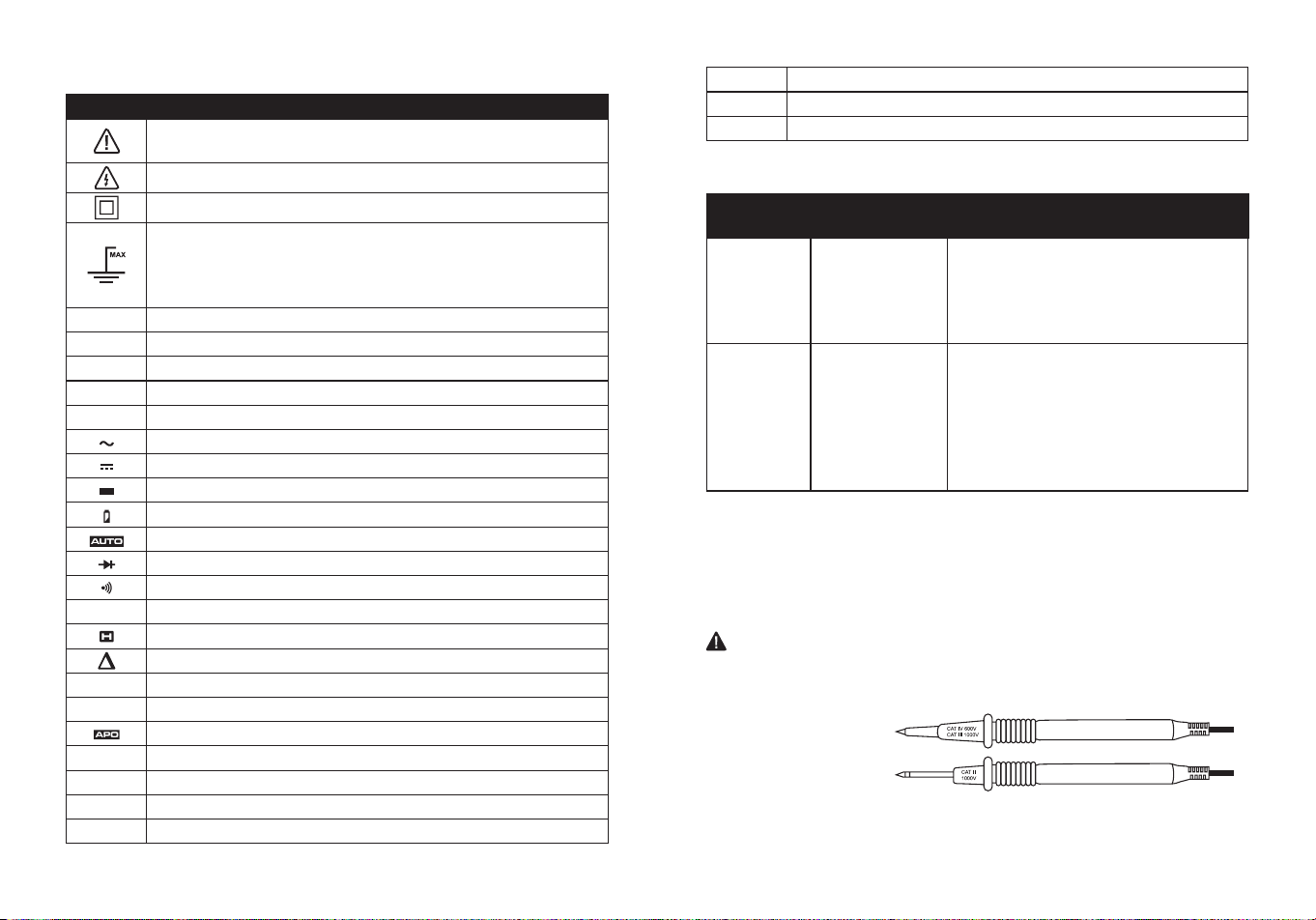
Symbols
PART DESCRIPTION
Potential danger. Indicates the user must refer to the
manual for important safety information.
Indicates hazardous voltages may be present.
Equipment is protected by double or reinforced insulation.
600V
This symbol advises the user that the terminal(s) so
marked must not be connected to a circuit point at which
the voltage with respect to earth ground exceeds (in this
case) 600 VAC or VDC.
NCV
Non-contact AC voltage measurements
V
Volts
A
Amperes
F
Farads(capacitance)
Ω
Ohms
Alternating current/voltage
Direct current
Minus sign
Low battery
Auto ranging
Diode test
Continuity
Hz
Hertz (frequency)
Display hold
Relative Mode
MAX
Maximum
MIN
Minimum
Auto power o
o
C
Centigrade
o
F
Fahrenheit
n
Nano (10
-9
)
μ
micro (10
-6
)
m
milli (10
-3
)
k
Kilo (10
3
)
M
Mega (10
6
)
CATEGORY
RATING
BRIEF
DESCRIPTION
TYPICAL APPLICATIONS
CAT II
Single phase
receptacles
and connected
loads.
- Household appliances, power tools.
- Outlets more than 30ft (10m) from a
CAT III source.
- Outlets more than 60ft (20m) from a
CAT IV source.
CAT III
Three phase
circuits and
single phase
lighting circuits
in commercial
buildings.
- Equipment in xed installations such
as 3-phase motors, switchgear and
distribution panels - Lighting circuits
in commercial buildings.
- Feeder lines in industrial plants.
- Any device or branch circuit that is
close to a CAT III source.
Safety Category Ratings
The measurement category (CAT) rating and voltage rating is
determined by a combination of the meter, test probes and any
accessories connected to the meter and test probes. The combination
rating is the LOWEST of any individual component.
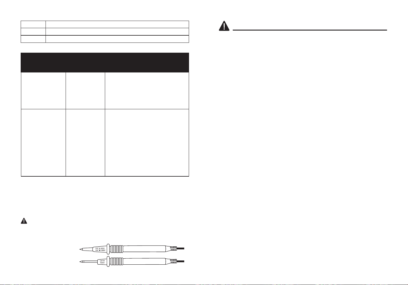
Test Leads
WARNING:
Operation is limited to CAT II applications when the
insulated tips are removed from one or both test probes. Refer to Input
Limits section in this manual for Maximum voltage ratings.
Insulated Tip On
Insulated Tip Removed
10 11
SAFETY INFORMATION
WARNINGS
●Please read and understand this entire manual before using this
product.
●Before changing functions using the selector switch, always
disconnect the test leads from the circuit under test.
●Ensure that the test leads are fully seated in the input jacks and keep
ngers away from the metal probe tips when taking measurements.
●Use only certied test leads with the proper safety category rating.
●Verify operation before using meter by measuring a known live
voltage.
●Use caution on live circuits. Voltages above 30 V AC rms, 42 V AC
peak, or 60 V DC pose a shock hazard.
●Comply with all applicable safety codes. Use approved personal
protective equipment when working near live electrical circuits-
particularly with regard to arc-ash potential.
●Do not use if the meter or test leads appear damaged.
●Do not use the meter or near explosive vapors. dust or gasses.
●Do not use the meter in wet or damp environments or during electrical
storms.
●Do not use the meter if it operates incorrectly. Protection may be
compromised.
●Do not operate meter while Low Battery warning is on. Replace
batteries immediately.
●Do not apply voltage or current that exceeds the meter's maximum
rated input limits.
PRODUCT COMPLIANCE
Users of this product are cautioned not to make modications or
changes. Doing so may void the compliance of this product with
applicable laws and regulatory requirements and may result in the loss
of the user's authority to operate the equipment.
"This device complies with part 15 of the FCC Rules. Its operation is
subject to the following two conditions: (1) This device may not cause
harmful interference, and (2) this device must accept any interference
received, including interference that may cause undesired operation."
Lowe’s Home Centers LLC
1000 Lowe’s Blvd.
Mooresville, NC 28117
1-888-3KOBALT (1-888-356-2258)
This equipment has been tested and found to comply with the limits
for a Class B digital device, pursuant to part 15 of the FCC Rules.
These limits are designed to provide reasonable protection against
harmful interference in a residential installation. This equipment
generates, uses and can radiate radio frequency energy and, if not
installed and used in accordance with the instructions, may cause
harmful interference to radio communications. However, there is no
guarantee that interference will not occur in a particular installation. If
this equipment does cause harmful interference to radio or television
reception, which can be determined by turning the equipment o and
on, the user is encouraged to try to correct the interference by one or
more of the following measures:
1. Reorient or relocate the receiving antenna.
2. Increase the separation between the equipment and receiver.
- Connect the equipment into an outlet on a circuit dierent from that to
which the receiver is connected.
- Consult the dealer or an experienced radio/TV technician for help.
"
CAUTION
: Changes or modications not expressly approved by the
party responsible for compliance could void the user's authority to
operate the equipment."

12 13
POWER ON/OFF
To power ON the meter, rotate the function selector switch from the
OFF setting to any measuremen t setting. To power OFF the meter,
rotate the function selector switch to the OFF setting.
RANGE Button
When the meter is rst turned on, it automatically goes into
Auto Ranging. This automatically selects the best range for the
measurements being made and is generally the best mode for most
measurements. For measurement situations requiring that a range be
manually selected, perform the following:
●Press the RANGE button. The “AUTO” display indicator will turn o.
●Press the RANGE button to step through the available ranges until
you select the range you want.
●Press and hold the RANGE button for 2 seconds to exit the Manual
Ranging mode and return to Auto Ranging.
MODE and REL Button
●Press the MODE Button to select AC voltages, AC/DC current,
Frequency, Ohms, Diode Test, Continuity, Capacitance and
Temperature.
●For AC/DC voltages, AC/DC current and Capacitance Zero & Oset
adjustment, press the REL Button for >2 second to activate or to exit
the REL function.
MAX/MIN Button
●Momentarily press the MAX/MIN button to activate the MAX/MIN
mode. The “MAX” indicator will appear on the LCD display. The meter
will display and hold the maximum reading and will update when a
higher “max” occurs.
●Momentarily press the MAX/MIN button again to view the lowest
reading. The “MIN” indicator meter will appear on the LCD display.
The meter will display and hold the minimum reading and will update
when a lower “min” occurs.
●Press and hold the MAX/MIN button to exit MAX/MIN and return to
normal operation.
OPERATING INSTRUCTIONS OPERATING INSTRUCTIONS
NOTE:
The meter does not auto range when the MAX/MIN mode is
active, the display will read OL if the range is exceeded. When this
occurs, exit MIN/NIN and use the RANGE button to select a high
range.
HOLD Button
●Press the HOLD Button to turn on or o the HOLD function.
Flashlight Button
●Press the Flashlight
Button to turn on or o the Flashlight function.
Auto Power O
●To extend battery life, the meter will automatically turn o in 15
minutes if there is no operation. To disable the auto power o feature,
hold down the MODE button and turn the meter on.
Low Battery Indication
●The icon will appear in the left corner of the display when the battery
voltage becomes low. Replace the battery when icon appears.
14 15
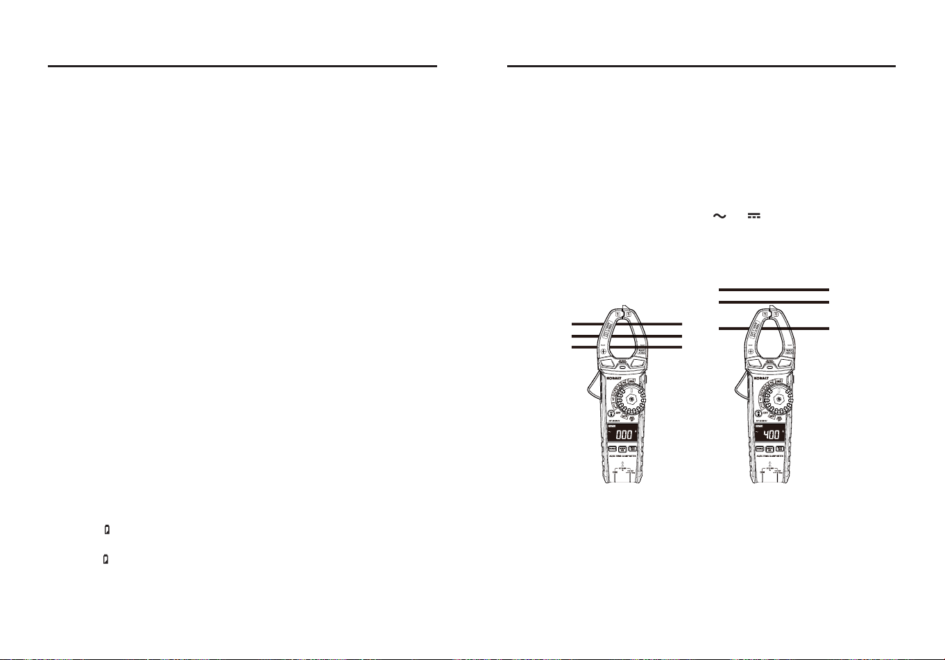
OPERATING INSTRUCTIONS
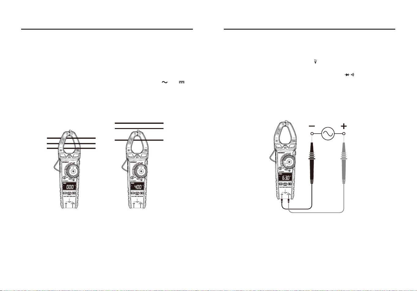
AC/DC Current Measurements
WARNING:
Ensure that the test leads are disconnected from the meter
before making current clamp measurements.
●Set the Function switch to the 40 A or 400 A AC/DC range.
●lf the range of the measured is not known, select the higher range
rst then move to the lower range if necessary.
●Press the MODE Button to select AC or DC current, the “ ” or “ ”
symbol will be shown on the LCD display.
●Press the trigger to open jaw, fully enclose one conductor to be
measured.
●The clamp meter LCD will display the reading.
Ground Wire
Ground Wire
Neutral Wire
Neutral Wire
Hot Wire
Hot Wire
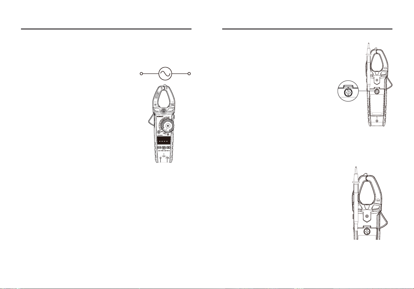
OPERATING INSTRUCTIONS
AC Voltage (Frequency) Measurements
WARNING:
Observe all safety precautions when working on live
voltages.
●Set the rotary function switch to the Hz position.
●Insert the black test lead banana plug into the COM jack.
●Insert the red test lead banana plug into the V Ω CAP Hz Temp
input jack.
●Connect the test leads in parallel to the circuit under test.
●Read the voltage on the LCD display.
●Press the MODE Button to indicate “Hz”.
●Read the frequency on the LCD display.
16 17
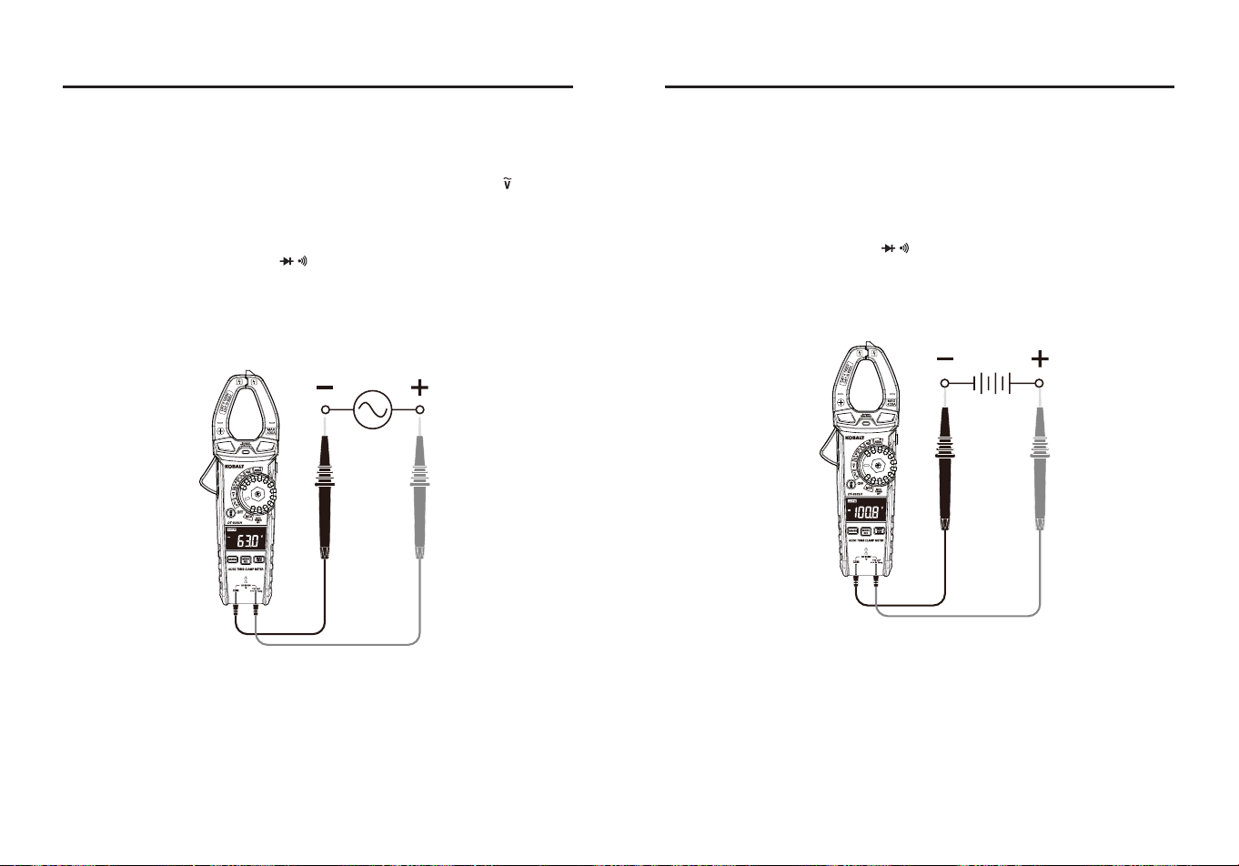
OPERATING INSTRUCTIONS
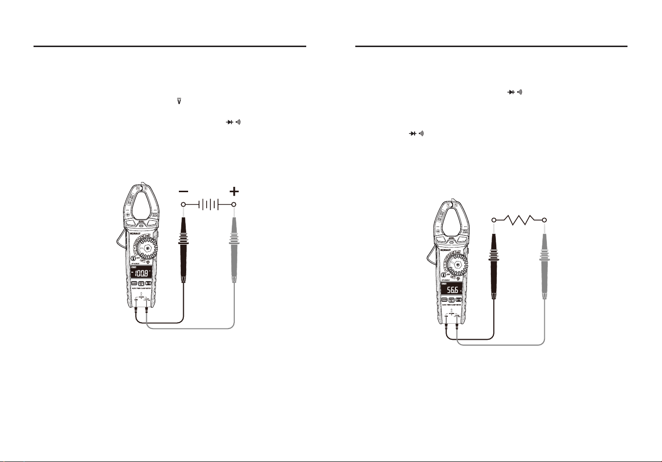
DC Voltage Measurements
WARNING:
Observe all safety precautions when working on live
voltages.
●Set the rotary function switch to the position.
●Insert the black test lead banana plug into the COM jack.
●Insert the red test lead banana plug into the V Ω CAP Hz Temp
input jack.
●Connect the test leads in parallel to the circuit under test.
●Read the voltage on the LCD display.
OPERATING INSTRUCTIONS
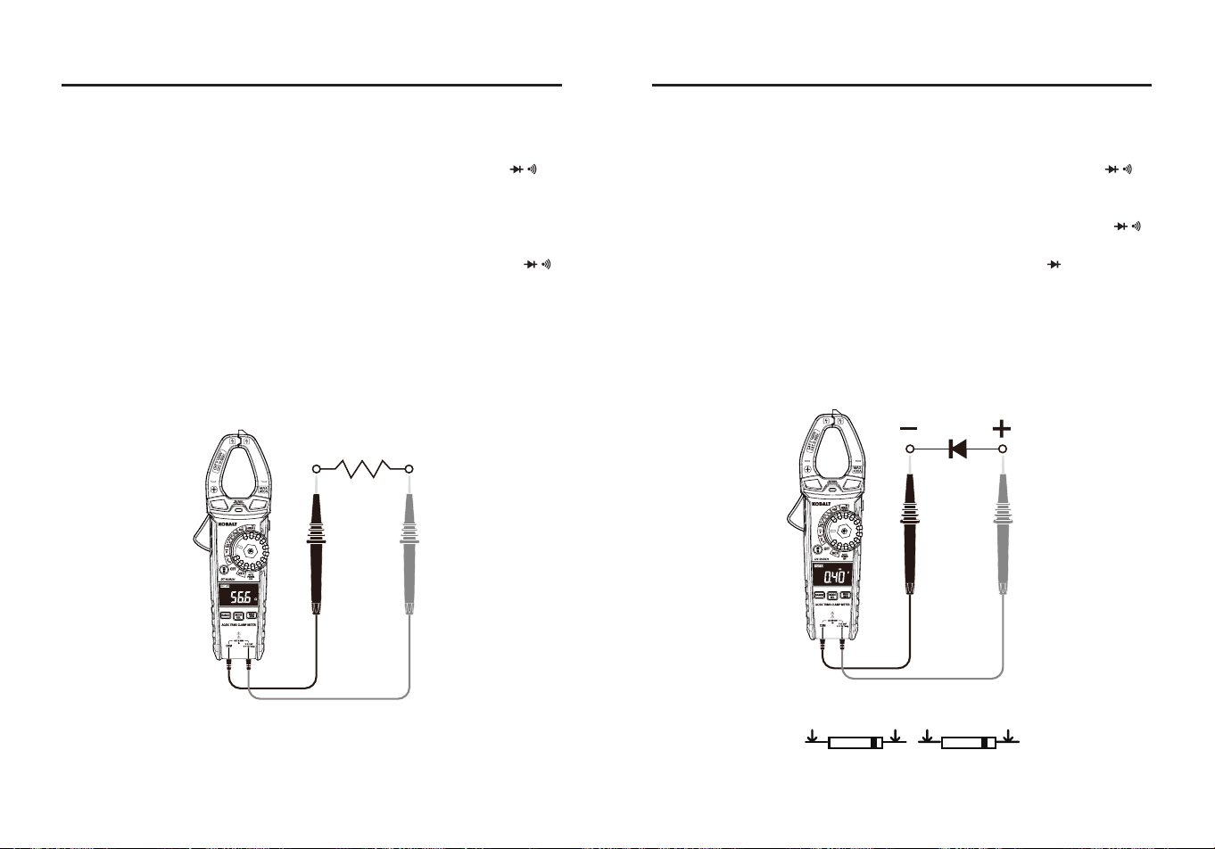
Resistance Measurements
WARNING:
Never test resistance on a live circuit.
●Set the rotary function switch to the Ω CAP position.
●Press the MODE button until the “Ω” symbol appears on the LCD
display.
●Insert the black test lead into the COM input jack and the red test lead
into the V Ω CAP Hz Temp input jack.
●Touch the test lead probes to the component under test. If the
component is installed in a circuit, it is best to disconnect one side
before testing to eliminate interference with other devices.
●Read the resistance on the LCD display.
18 19
OPERATING INSTRUCTIONS
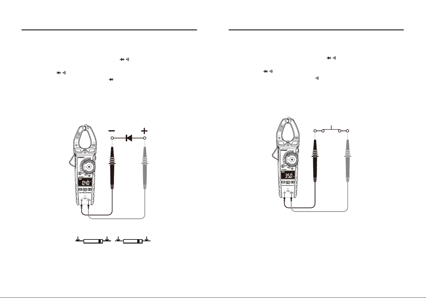
Diode Test
WARNING:
Never test diodes in a live circuit.
●Set the rotary function switch to the Ω CAP position.
●Insert the black test lead into the COM input jack and the red test lead
into the V Ω CAP Hz Temp input jack.
●Press the MODE button until the “ ” symbol appears on the LCD
display.
●Touch the test lead probes to the diode under test.
●Forward voltage will indicate 0.4V to 0.7V on the LCD display.
Reverse voltage will indicate “OL”. Shorted devices will indicate near
0V and an open device will indicate “OL” in both polarities.
Forward test Reverse test
Red
Probe
Red
Probe
Black
Probe
Black
Probe
OPERATING INSTRUCTIONS
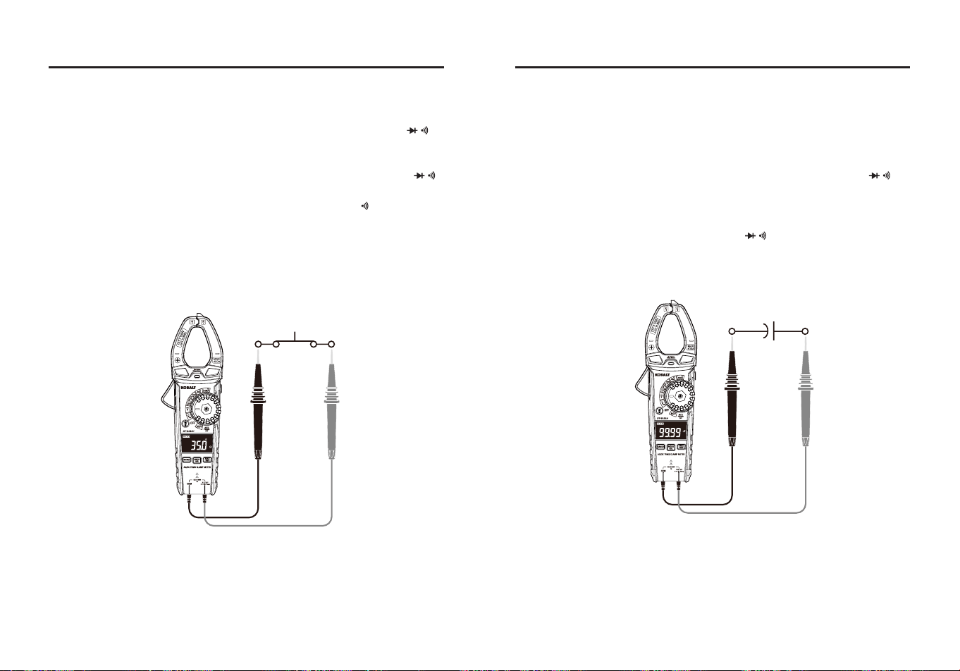
Continuity Test
WARNING:
Never test continuity on a live circuit.
●Set the rotary function switch to the Ω CAP position.
●Insert the black test lead into the COM input jack and the red test lead
into the V Ω CAP Hz Temp input jack.
●Press the MODE button until the “ ” symbol appears on the LCD
display.
●Touch the test lead probes to the device or wire under test.
●A beeper will sound if the resistance is approx. 50 ohms or less and
the resistance reading will be shown on the LCD display.
20 21
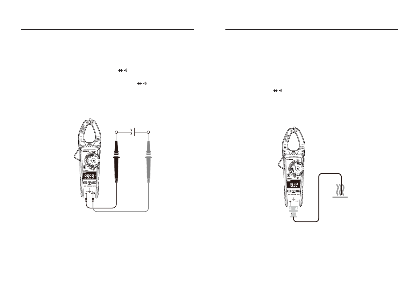
OPERATING INSTRUCTIONS
Capacitance Measurements
WARNING:
To avoid electric shock, disconnect power to the unit
under test and discharge all capacitors before taking any capacitance
measurements. Remove the batteries and unplug the line cords.
●Set the rotary function switch to the Ω CAP position.
●Insert the black test lead banana plug into the COM Input Jack; Insert
the red test lead banana plug into the the V Ω CAP Hz Temp
input jack.
●Touch the test leads to the capacitor to be tested.
●Read the capacitance on the LCD display.
OPERATING INSTRUCTIONS
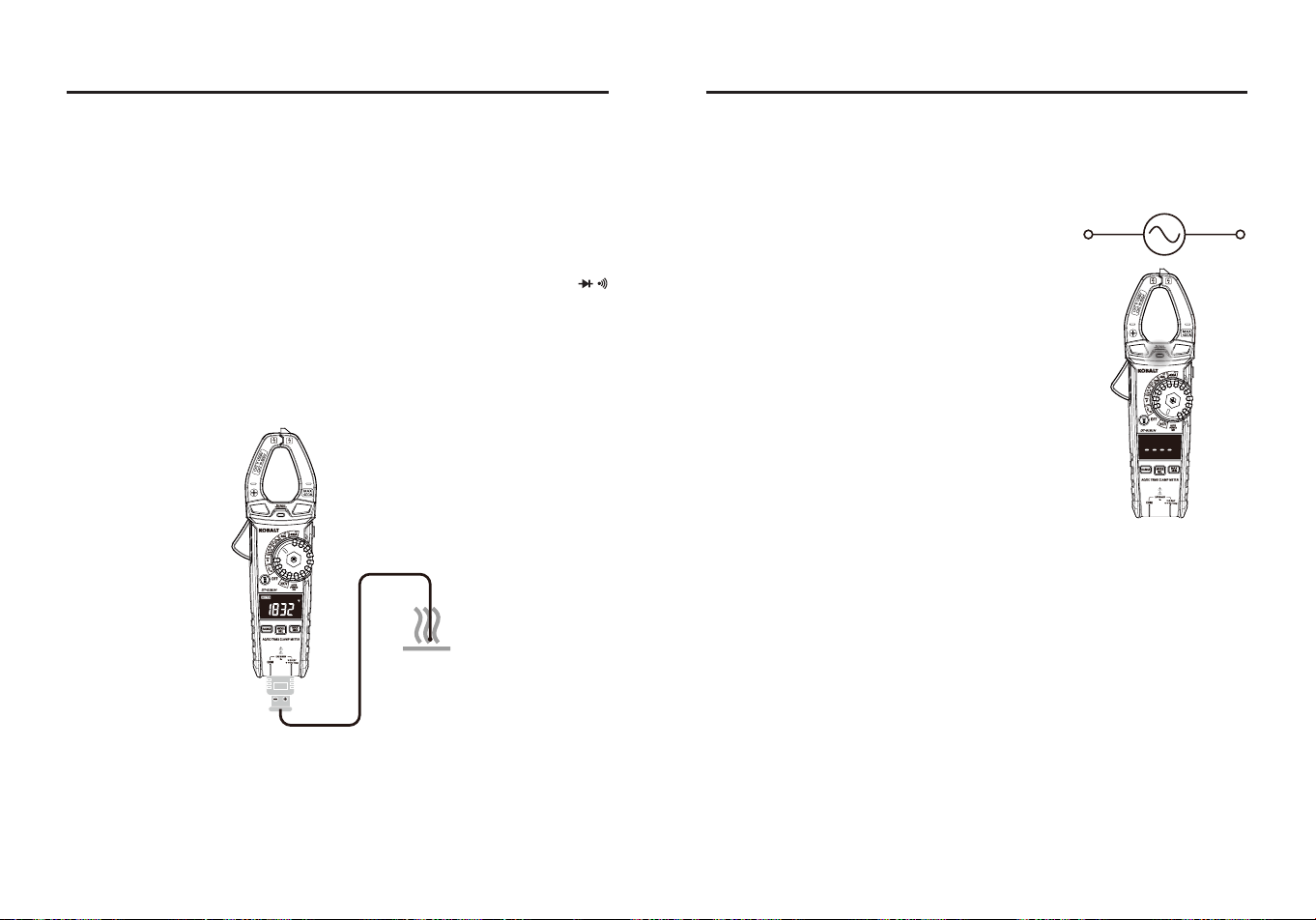
Temperature Measurements
WARNING:
Do not touch the temperature probe to live circuits.
●Set the rotary function switch to the Temp °C °F Position.
●Press the MODE button to select readings in °F or °C.
●Connect the temperature probe to the Banana Plug Adapter, note the
– and + markings on the adapter, connect the adapter to the meter,
making sure the – side goes into the COM input jack and the + side
goes into the V Ω CAP Hz Temp input jack.
●Touch the tip of the temperature probe to the object being measured,
keep the probe touching the object until the reading stabilizes.
●Read the temperature on the LCD display.
22 23
OPERATING INSTRUCTIONS
Non-contact AC Voltage Detector
WARNING:
Risk of Electrocution. Before use, always test the Voltage
Detector on a known live circuit to verify proper operation.
●Set the rotary function switch to the NCV
position.
●Hold the detector close to the AC voltage
being tested.
●If no voltag is detected, the LCD will show
“EF“, NCV indicator light will not ash and
there will be no beeper sound.
●According to the detected voltage eld, the
LCD will display dierent horizontal lines.
When the voltage eld is strongest, LCD
displays four horizontal lines, when the
voltage eld is weakest, only one line. At the
same time, the NCV indicator light ashes,
the beeper will make a dierent sound.
NOTE:
●The conductors in electrical cord sets are often twisted. For best
results, rub the probe tip along a length of the cord to assure placing
the tip in close proximity to the live conductor.
●The detector is designed with high sensitivity. Static electricity or
other sources of energy may randomly trip the sensor. This is normal
operation.
●Insulation type and thickness, distance from the voltage source,
shielded wires, and other factors may aect reliable operation. Use
other methods to verify live voltage, if there is any uncertainty.
OPERATING INSTRUCTIONS
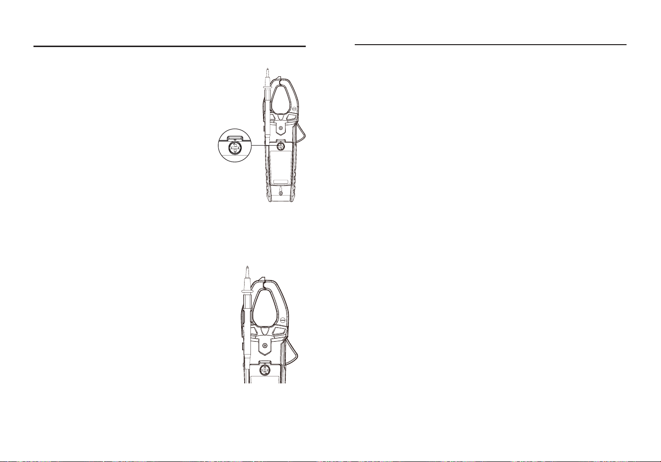
Battery Replacement
WARNINGS:
To avoid electric shock,
disconnect the test leads from any source of
voltage before removing the battery cover. DO
NOT operate this meter until the battery cover
has been properly secured.
●Use small coin to unlock battery door.
●Lift up on tab below lock to remove battery
door.
●Replace battery with three AAA 1.5 V
batteries.
●Install the battery cover and lock the battery
cover securely.
WARNINGS:
To avoid electric shock, do not operate your meter until
the battery covers is in place and fastened securely.
Two-Hand Operation
For convenience,the user can attach the
negative test lead to the clamp for two-handed
operation.

24 25
CARE AND MAINTENANCE
Keep the meter dry. If it gets wet, wipe it o.
Keep the meter clean. Wipe the dirt with a soft cloth dampened with
water. Do not use chemicals, cleaning solvents, or detergents.
Use and store the meter in normal temperatures. Temperature
extremes can shorten the life of the electronic parts and distort or
melt plastic parts.
Handle the meter gently and carefully. Dropping it can damage the
electronic parts or the case.
Use only fresh batteries of the recommended size and type. Batteries
are to be inserted with the correct polarity. Remove old or weak
batteries so they do not leak and damage the unit.
Do not mix old and new batteries. Do not mix different types of
batteries such as alkaline, carbon-zinc, or rechargeable batteries.
Non-rechargeable batteries are not to be recharged.
If the meter is to be stored for a long period of time, the batteries
should be removed to prevent damage to the unit.
WARRANTY
Three-year warranty. Incidental or consequential damages are excluded from this
warranty.
Printed in China
TROUBLESHOOTING
PROBLEM POSSIBLE CAUSE CORRECTIVE ACTION
No reading on the
LCD display
1.Batteries are weak.
2.Batteries are not
correctly installed.
3.Rusty battery pole
piece.
4.The LCD / meter is
damaged.
1.Replace batteries.
2.Install batteries
observing polarity
shown inside battery
compartment.
3.Wipe the battery pole
piece.
4.Replace meter.
Current range
measures normal,
but voltage/
resistance
measure
abnormal
1.Test leads are
broken.
2.Input stud loose.
3.Low battery symbol
shows on LCD
display.
1.Replace test leads.
2.Strengthen the input
stud contact.
3.Replace batteries.
Voltage/resistance
measures
normal, but
current measures
abnormal
Poor jaw contact.
Make sure the jaws are
fully closed.
Abnormal noise
appears inside the
device
Loose parts.
Open the back cover to
check and clean up.

26 27
ARTÍCULO #5996929
MODELO #DT-9181H
400A DE CA/CC TRMS
PINZA MEDIDORA
KOBALT y el diseño del logotipo
son marcas comerciales o marcas
registradas de LF, LLC. Todos los
derechos reservados.
Número de serie
Fecha de compra
SG24726
Gracias por adquirir este producto KOBALT. ¿Tiene problemas o le
faltan piezas?
Antes de devolverlo, póngase en contacto con nosotros en el
888-356-2258
, 8 de la mañana a 8 de la tarde, hora del Este, de
lunes a domingo o
ADJUNTE AQUÍ SU RECIBO
ÍNDICE
Especicaciones del producto ..............................................................28
Contenido del paquete .........................................................................31
Información de seguridad .....................................................................35
Instrucciones de funcionamiento ..........................................................37
Cuidado y mantenimiento .....................................................................49
Resolución de problemas .....................................................................50
Garantía................................................................................................51
28 29
ESPECIFICACIONES DEL PRODUCTO
ESPECIFICACIONES GENERALES
Tamaño de la pinza Abertura de 30 mm (1,18 pulg.) aprox.
Sobretensión CAT III 600 V
Prueba de diodos
Corriente de prueba 1 mA máx.; tensión
de circuito abierto de 2 V típica
Prueba de continuidad Señal acústica si la resistencia es <50 Ω
Indicación de batería baja “ ” aparece en pantalla
Pantalla LCD de 4000 recuentos
Indicación de sobrecarga Aparece "OL"
Polaridad
Aparece el símbolo "-" para polaridad
negativa
Tasa de medición 3 lecturas por segundo, nominal
Apagado automático Aprox. 15 minutos
Impedancia de entrada Aprox. 10 MΩ (VDC y VAC)
Respuesta de CA Respuesta True RMS
Ancho de banda de
tensión de CA
50 a 1 kHz
Ancho de banda de la
corriente alterna
50 a 60 Hz
Baterías Tres pilas AAA de 1,5 V
Entorno de
funcionamiento
5 a 40 °C (41 a 104 °F) a <75 % de
humedad relativa
Entorno de
almacenamiento
14 a 122 °F (-10 a 50 °C) a 80 % máx.
hasta 87 °F (31 °C), disminuyendo
linealmente hasta 50 % a 104 °F (40 °C)
Altitud de funcionamiento 7000 pies (2000 m) máximo
Dimensiones
Aprox. 8,8x3,0x1,55 pulg. (224x76x39,5
mm)
Peso neto Aprox. 0,59 libras (267 g)
Seguridad
Conforme a: UL STD 61010-1.61010-
2.032
Certicado según: CSA STD C222#
61010-1. 61010-2-032: EN 61010-1.
61010-2-032
FUNCIÓN
TENSIÓN/CORRIENTE DE
ENTRADA MÁXIMA
Tensión CA o CC 600 V DE CA/CC
Resistencia, continuidad,
prueba de diodos,
capacitancia, temperatura
250 V DE CA/CC
Corriente CA o CC 400 A
Frecuencia 600 V DE CA/CC
Input Limits
Especicaciones
FUNCIÓN RANGO RESOLUCIÓN PRECISIÓN
Tensión alterna
de CA 50 a 1
kHz
4 V 0,001 V
±(1,2 %+5 dígitos)
40 V 0,01 V
400 V 0,1 V
600 V 1 V
Todos los rangos de tensión de CA están
especicados desde el 5 % del rango hasta el 100
% del rango.
Ancho de banda de la tensión de CA: 50 a 60 Hz
(todas las ondas); 50 a 1 kHz (onda sinusoidal).
Tensión de CC
400 mV 0,1 mV ±(0,5 %+5 dígitos)
4 V 0,001 V
±(0,5 %+8 dígitos)
40 V 0,01 V
400 V 0,1 V
600 V 1 V
Corriente
alterna de 50 a
60 Hz
40 A 0,01 A ±(2,5 %+10 dígitos)
400 A 0,1 A ±(2,8 %+8 dígitos)
Todos los rangos de corriente alterna están
especicados desde el 5 % del rango hasta el 100
% del rango.
Corriente
continua
40 A 0,01 A ±(2,5 %+8 dígitos)
400 A 0,1 A ±(2,8 %+8 dígitos)
ESPECIFICACIONES DEL PRODUCTO
30 31
FUNCIÓN RANGO RESOLUCIÓN PRECISIÓN
Resistencia
400 Ω 0,1 Ω
±(1,2 %+5 dígitos)
4 kΩ 0,001 kΩ
40 kΩ 0,01 kΩ
400 kΩ 0,1 kΩ
4 MΩ 0,001 MΩ ±(2,0 %+5 dígitos)
40 MΩ 0,01 MΩ ±(3,0 %+8 dígitos)
Capacitancia
4 nF 0,001 nF ±(3,5 %+60 dígitos)
40 nF 0,01 nF
±(3,0 %+10 dígitos)
400 nF 0,1 nF
4 µF 0,001 µF
±(3,8 %+5 dígitos)
40 µF 0,01 µF
400 µF 0,1 µF
±(3,5 %+5 dígitos)
4 mF 0,001 mF
Frecuencia
4 Hz 0,001 Hz
±(1,2 %+5 dígitos)
40 Hz 0,01 Hz
400 Hz 0,1 Hz
4 kHz 0,001 kHz
10 kHz 0,01 kHz
Sensibilidad: >15 V RMS.
Temperatura
-18 a 1000 °C 1 °C ±(1,5 %+5 °C)
0 a 1832 °F 1 °F ±(1,5 %+9 °F)
La precisión se establece entre 18 y 28 °C (65 y 83 °F) y menos del 75
% de humedad relativa.
Las especicaciones de precisión constan de dos elementos:
(% de lectura): se trata de la precisión del circuito de medición.
(+ dígitos): esta es la precisión del convertidor analógico a digital.
ESPECIFICACIONES DEL PRODUCTO
BA C
D E
PIEZA DESCRIPCIÓN CANTIDAD
A Medidor con abrazadera 1
B Estuche de transporte 1
C Conductores de prueba 1
D Sonda de temperatura tipo K 1
E Batería de 1.5 voltios 3
CONTENIDO DEL PAQUETE
32 33
CONTENIDO DEL PAQUETE
PIEZA DESCRIPCIÓN
A Detector de tensión sin contacto
B Indicador de tensión sin contacto
C Pinza disparadora
D Soporte del cable de prueba
E Botón HOLD
F Interruptor de función giratorio
G Botón linterna
H Pantalla LCD
I Botón RANGO
J Botón MAX/MIN
K Botón MODE y relativo
L Inserto magnético para la correa
M Tapa de las pilas
N Detector de tensión sin contacto
O V, Ω, CAP, , , Hz, Toma de entrada de temperatura
NOTA
: Retire la película de plástico de la pantalla LCD antes de
utilizarla.
A
B
C
G
I
K
F
M
N
L
O
E
D
H
J
Símbolos
PIEZA DESCRIPCIÓN
Peligro potencial. Indica que el usuario debe consultar el
manual para obtener información de seguridad importante.
Indica que puede haber tensiones peligrosas.
El equipo está protegido por un aislamiento doble o
reforzado.
600V
Este símbolo advierte al usuario de que el terminal o
terminales así marcados no deben conectarse a un punto
del circuito en el que la tensión con respecto a tierra supere
(en este caso) los 600 VCA o VCC.
NCV
Mediciones de tensión alterna sin contacto
V
Voltios
A
Amperios
F
Faradios (capacitancia)
Ω
Ohmios
Corriente/tensión alterna
Corriente continua
Signo menos
Batería baja
Escala automática
Prueba de diodos
Continuidad
Hz
Hertz (frecuencia)
Retención de pantalla
Modo relativo
MAX
Máximo
MIN
Mínimo
Apagado automático
o
C
Centígrado
o
F
Fahrenheit
n
Nano (10
-9
)
μ
micro (10
-6
)
34 35
m
milli (10
-3
)
k
Kilo (10
3
)
M
Mega (10
6
)
CLASIFICACIÓN
POR
CATEGORÍAS
BREVE
DESCRIPCIÓN
APLICACIONES TÍPICAS
CAT II
Receptáculos
monofásicos
y cargas
conectadas.
-Electrodomésticos, herramientas
eléctricas.
-Enchufes a más de 10 m (30
pies) de una fuente CAT III.
- Enchufes a más de 20 m (60
pies) de una fuente CAT IV.
CAT III
Circuitos
trifásicos y
circuitos de
iluminación
monofásicos
en edicios
comerciales.
-Equipos en instalaciones
jas como motores trifásicos,
aparamenta y cuadros de
distribución - Circuitos de
alumbrado en edicios
comerciales.
-Líneas de alimentación en
plantas industriales.
-Cualquier dispositivo o circuito
derivado que esté cerca de una
fuente CAT III.
Clasicaciones de las categorías de seguridad
La clasicación de la categoría de medición (CAT) y la clasicación de
la tensión vienen determinadas por la combinación del medidor, las
puntas de prueba y cualquier accesorio conectado al medidor y a las
puntas de prueba. La clasicación de la combinación es la MÁS BAJA
de cualquier componente individual.
Cables de prueba
AVISO:
El funcionamiento está limitado a aplicaciones CAT II
cuando se retiran las puntas aisladas de una o ambas puntas de
prueba. Consulte la sección "Límites de entrada" de este manual para
conocer los valores máximos de tensión.
Punta aislante puesta
Punta aislante retirada
INFORMACIÓN DE SEGURIDAD
AVISOS
●Lea y comprenda todo este manual antes de utilizar este producto.
●Antes de cambiar de función utilizando el conmutador selector,
desconecte siempre los cables de prueba del circuito sometido a
prueba.
●Asegúrese de que los cables de prueba están completamente
asentados en las tomas de entrada y mantenga los dedos alejados
de las puntas de las sondas metálicas cuando realice mediciones.
●Utilice únicamente cables de prueba certicados con la clasicación
de categoría de seguridad adecuada.
●Verique el funcionamiento antes de utilizar el medidor midiendo una
tensión viva conocida.
●Tenga precaución en circuitos con tensión. Las tensiones superiores
a 30 V CA rms, 42 V CA pico o 60 V CC suponen un riesgo de
descarga.
●Cumpla todos los códigos de seguridad aplicables. Utilice equipo de
protección personal homologado cuando trabaje cerca de circuitos
eléctricos en tensión, especialmente en lo que se reere al potencial
de arco eléctrico.
●No lo utilice si el medidor o los cables de prueba parecen estar
dañados.
●No utilice el medidor ni cerca de vapores, polvo o gases explosivos.
●No utilice el medidor en entornos húmedos o mojados ni durante
tormentas eléctricas.
●No utilice el medidor si funciona de forma incorrecta. La protección
puede verse comprometida.
●No utilice el medidor mientras esté encendido el aviso de batería
baja. Sustituya las pilas inmediatamente.
●No aplique voltaje o corriente que exceda los límites de entrada
nominal máxima del medidor.

36 37
CONFORMIDAD DEL PRODUCTO
Se advierte a los usuarios de este producto que no realicen
modicaciones ni cambios. Hacerlo puede anular la conformidad de
este producto con las leyes y requisitos reglamentarios aplicables y
puede dar lugar a la pérdida de la autoridad del usuario para utilizar el
equipo.
"Este aparato cumple la parte 15 de las normas de la FCC. Su
funcionamiento está sujeto a las dos condiciones siguientes: (1) Este
dispositivo no puede causar interferencias perjudiciales, y (2) este
dispositivo debe aceptar cualquier interferencia recibida, incluidas las
interferencias que puedan causar un funcionamiento no deseado".
Lowe's Home Centers LLC 1000 Lowe's Blvd.
Mooresville, NC 28117
1-888-3KOBALT (1-888-356-2258)
Este equipo ha sido probado y se ha determinado que cumple con
los límites para un dispositivo digital de Clase B, de conformidad con
la parte 15 de las normas de la FCC. Estos límites están diseñados
para proporcionar una protección razonable contra interferencias
perjudiciales en una instalación residencial. Este equipo genera,
utiliza y puede irradiar energía de radiofrecuencia y, si no se instala y
utiliza de acuerdo con las instrucciones, puede causar interferencias
perjudiciales en las comunicaciones por radio. Sin embargo, no existe
ninguna garantía de que no se produzcan interferencias en una
instalación concreta. Si este equipo causa interferencias perjudiciales
en la recepción de radio o televisión, lo que puede determinarse
apagando y encendiendo el equipo, se recomienda al usuario que
intente corregir las interferencias mediante una o varias de las
siguientes medidas:
1.Reorientar o reubicar la antena receptora.
2.Aumentar la separación entre el equipo y el receptor.
ENCENDIDO/APAGADO
Para encender el medidor, gire el conmutador selector de funciones
desde la posición de apagado hasta cualquier posición de medición.
Para apagar el medidor, gire el conmutador selector de funciones
hasta la posición de apagado.
Botón RANGO
Cuando el medidor se enciende por primera vez, pasa
automáticamente al modo de alcance automático. Esto selecciona
automáticamente el mejor rango para las mediciones que se están
realizando y es generalmente el mejor modo para la mayoría de las
mediciones. Para situaciones de medición que requieran que se
seleccione manualmente un rango, realice lo siguiente:
●Pulse el botón de RANGO. El indicador "AUTO" de la pantalla se
apagará.
●Pulse el botón de RANGO para recorrer los rangos disponibles hasta
seleccionar el rango que desee.
●Mantenga pulsado el botón de RANGO durante 2 segundos para salir
del modo de alcance manual y volver al de alcance automático.
Botón MODO y REL
●Pulse el botón MODO para seleccionar tensiones CA, corriente
DE CA/CC, frecuencia, ohmios, prueba de diodos, continuidad,
capacitancia y temperatura.
●Para las tensiones de CA/CC, la corriente de CA/CC y el ajuste de
cero y desviación de la capacitancia, pulse el botón REL durante >2
segundos para activar o salir de la función REL.
INSTRUCCIONES DE FUNCIONAMIENTO
-Conecte el equipo a una toma de corriente de un circuito distinto al
que está conectado el receptor.
-Consulte al distribuidor o a un técnico experto en radio/TV para
obtener ayuda.
"
PRECAUCIÓN:
Los cambios o modicaciones no aprobados
expresamente por la parte responsable del cumplimiento podrían
anular la autoridad del usuario para utilizar el equipo".
38 39
Botón MAX/MIN
●Pulse momentáneamente el botón MAX/MIN para activar el modo
MAX/MIN. El indicador "MAX" aparecerá en la pantalla LCD. El
medidor mostrará y mantendrá la lectura máxima y se actualizará
cuando se produzca un "máx." superior.
●Vuelva a pulsar momentáneamente el botón MAX/MIN para ver la
lectura más baja. El medidor indicador de "MIN" aparecerá en la
pantalla LCD. El medidor mostrará y mantendrá la lectura mínima y
se actualizará cuando se produzca un "mín." más bajo.
●Mantenga pulsado el botón MAX/MIN para salir de MAX/MIN y volver
al funcionamiento normal.
INSTRUCCIONES DE FUNCIONAMIENTO
NOTA:
El medidor no tiene escala automática cuando el modo MAX/
MIN está activo, la pantalla mostrará OL si se sobrepasa la escala.
Cuando esto ocurra, salga de MIN/NIN y utilice el botón RANGO para
seleccionar un rango alto.
Botón MANTENER
●Pulse el botón MANTENER para activar o desactivar la función
MANTENER.
Botón de la linterna
●Pulse el botón de la linterna para activar o desactivar la función de
linterna.
Apagado automático
●Para prolongar la duración de la pila, el medidor se apagará
automáticamente en 15 minutos si no hay ninguna operación. Para
desactivar la función de apagado automático, mantenga pulsado el
botón MODO y encienda el medidor.
Indicación de batería baja
●El ícono aparecerá en la esquina izquierda de la pantalla cuando el
voltaje de la batería sea bajo. Sustituya la batería cuando aparezca
el ícono .
INSTRUCCIONES DE FUNCIONAMIENTO
Medidas actuales de CA/CC
AVISO:
Asegúrese de que los cables de prueba están desconectados
del medidor antes de realizar las mediciones de la pinza amperimétrica.
●Coloque el interruptor de función en el rango de 40 A o 400 A de CA/
CC.
●Si no se conoce el rango de lo medido, seleccione el rango superior
primero y luego pase al rango inferior si es necesario.
●Pulse el botón MODO para seleccionar la corriente CA o CC, en la
pantalla LCD aparecerá el símbolo “ ” o “ ” .
●Pulse el disparador para abrir la mordaza, encierre completamente
un conductor a medir.
●La pantalla LCD de la pinza amperimétrica mostrará la lectura.
Cable de masa
Cable de masa
Cable neutro
Cable neutro
Cable caliente
Cable caliente
40 41
INSTRUCCIONES DE FUNCIONAMIENTO
Medidas de tensión alterna (frecuencia)
AVISO:
Respete todas las precauciones de seguridad cuando trabaje
con tensión.
●Coloque el conmutador rotativo de funciones en la posición Hz.
●Inserte el conector banana del cable negro de prueba en la toma
COM.
●Inserte el conector banana del cable rojo de prueba en la toma de
entrada de temperatura V Ω CAP Hz.
●Conecte los cables de prueba en paralelo al circuito bajo prueba.
●Lea la tensión en la pantalla LCD.
●Pulse el botón MODO para indicar "Hz".
●Lea la frecuencia en la pantalla LCD.
INSTRUCCIONES DE FUNCIONAMIENTO
Medidas de tensión en CC
AVISO:
Observe todas las precauciones de seguridad cuando trabaje
con tensiones vivas.
●Coloque el conmutador de funciones giratorio en la posición.
●Inserte la clavija banana del cable negro de prueba en la toma COM.
●Inserte el conector banana del cable rojo de prueba en la toma de
entrada de temperatura V Ω CAP Hz.
●Conecte los cables de prueba en paralelo al circuito bajo prueba.
●Lea la tensión en la pantalla LCD.
42 43
Medidas de resistencia
AVISO:
Nunca pruebe la resistencia en un circuito bajo tensión.
●Coloque el conmutador rotativo de funciones en la posición Ω
CAP.
●Pulse el botón MODO hasta que aparezca el símbolo "Ω" en la
pantalla LCD.
●Inserte el cable de prueba negro en la toma de entrada COM y el
cable de prueba rojo en la toma de entrada de temperatura V Ω
CAP Hz.
●Toque con las puntas de los cables de prueba el componente a
comprobar. Si el componente está instalado en un circuito, es mejor
desconectar un lado antes de la prueba para eliminar interferencias
con otros aparatos.
●Lea la resistencia en la pantalla LCD.
INSTRUCCIONES DE FUNCIONAMIENTO
Prueba de diodos
AVISO:
Nunca pruebe los diodos en un circuito bajo tensión.
●Coloque el conmutador de funciones giratorio en la posición Ω
CAP.
●Inserte el cable de prueba negro en la toma de entrada COM y el
cable de prueba rojo en la toma de entrada de temperatura V Ω
CAP Hz.
●Pulse el botón MODO hasta que aparezca el símbolo “ ” en la
pantalla LCD.
●Toque con las puntas de prueba el diodo bajo prueba.
●La tensión directa indicará de 0,4 V a 0,7 V en la pantalla LCD.
La tensión inversa indicará "OL". Los dispositivos cortocircuitados
indicarán cerca de 0 V y un dispositivo abierto indicará "OL" en
ambas polaridades.
Prueba hacia
delante
Prueba hacia atrás
Sonda
roja
Sonda
roja
Sonda
negra
Sonda
negra
INSTRUCCIONES DE FUNCIONAMIENTO
44 45
Prueba de continuidad
AVISO:
Nunca pruebe la continuidad en un circuito bajo tensión.
●Coloque el conmutador de funciones giratorio en la posición Ω
CAP.
●Inserte el cable de prueba negro en la toma de entrada COM y el
cable de prueba rojo en la toma de entrada de temperatura V Ω
CAP Hz.
●Pulse el botón MODO hasta que aparezca el símbolo “ ” en la
pantalla LCD.
●Toque con las puntas de los cables de prueba el aparato o cable a
comprobar.
●Sonará un pitido si la resistencia es de aprox. 50 ohmios o menos y
la lectura de la resistencia se mostrará en la pantalla LCD.
INSTRUCCIONES DE FUNCIONAMIENTO
Mediciones de capacitancia
AVISO:
Para evitar descargas eléctricas, desconecte la alimentación
de la unidad bajo prueba y descargue todos los condensadores antes
de realizar cualquier medición de capacitancia. Retire las pilas y
desenchufe los cables de línea.
●Coloque el conmutador rotativo de funciones en la posición Ω
CAP.
●Inserte el conector banana del cable negro de prueba en la toma de
entrada COM; inserte el conector banana del cable rojo de prueba en
la toma de entrada de temperatura V Ω CAP Hz.
●Toque con los cables de prueba el condensador a probar.
●Lea la capacitancia en la pantalla LCD.
INSTRUCCIONES DE FUNCIONAMIENTO
46 47
Mediciones de temperatura
AVISO:
No toque la sonda de temperatura con circuitos bajo tensión.
●Coloque el selector giratorio de funciones en la posición Temp °C °F.
●Pulse el botón MODE para seleccionar las lecturas en °F o °C.
●Conecte la sonda de temperatura al adaptador de enchufe banana,
observe las marcas - y + del adaptador, conecte el adaptador al
medidor, asegurándose de que el lado - entra en la toma de entrada
COM y el lado + entra en la toma de entrada de temperatura V Ω
CAP Hz.
●Toque con la punta de la sonda de temperatura el objeto a medir,
mantenga la sonda en contacto con el objeto hasta que la lectura se
estabilice.
●Lea la temperatura en la pantalla LCD.
INSTRUCCIONES DE FUNCIONAMIENTO
Detector de tensión alterna sin contacto
AVISO:
Riesgo de electrocución. Antes de utilizarlo, pruebe siempre el
detector de tensión en un circuito con tensión conocida para vericar
su correcto funcionamiento.
●Coloque el interruptor de función giratorio
en la posición NCV.
●Sostenga el detector cerca de la tensión
alterna que se está comprobando.
●Si no se detecta ninguna tensión, la pantalla
LCD mostrará "EF", la luz indicadora NCV
no parpadeará y no se emitirá ningún pitido.
●Según el campo de tensión detectado, la
pantalla LCD mostrará diferentes líneas
horizontales. Cuando el campo de tensión
es más fuerte, la pantalla LCD muestra
cuatro líneas horizontales, cuando el
campo de tensión es más débil, solo una
línea. Al mismo tiempo, la luz indicadora
NCV parpadea, la señal acústica emitirá un
sonido diferente.
NOTA:
●Los conductores de los juegos de cables eléctricos suelen estar
retorcidos. Para obtener mejores resultados, frote la punta de la
sonda a lo largo de un tramo del cable para asegurarse de colocar la
punta muy cerca del conductor bajo tensión.
●El detector está diseñado con una alta sensibilidad. La electricidad
estática u otras fuentes de energía pueden disparar aleatoriamente el
sensor. Se trata de un funcionamiento normal.
●El tipo y grosor del aislamiento, la distancia a la fuente de tensión, los
cables apantallados y otros factores pueden afectar al funcionamiento
able. Utilice otros métodos para vericar la tensión viva, si hay
alguna incertidumbre.
INSTRUCCIONES DE FUNCIONAMIENTO
48 49
INSTRUCCIONES DE FUNCIONAMIENTO
Sustitución de las pilas
AVISOS:
Para evitar descargas eléctricas,
desconecte los cables de prueba de cualquier
fuente de tensión antes de retirar la tapa de las
pilas. NO utilice este medidor hasta que la tapa
del compartimento de la pila esté bien sujeta.
●Utilice una moneda pequeña para
desbloquear la tapa de las pilas.
●Levante la lengüeta situada debajo del cierre
para extraer la tapa de las pilas.
●Sustituya las pilas por tres pilas AAA de 1,5 V.
●Instale la tapa de las pilas y bloquéela
rmemente.
AVISOS:
Para evitar descargas eléctricas, no utilice su medidor hasta
que las tapas de las pilas estén colocadas y bien sujetas.
Funcionamiento con dos manos
Para mayor comodidad, el usuario puede jar
el cable de prueba negativo a la pinza para
manejarlo con las dos manos.
CUIDADO Y MANTENIMIENTO
●Mantenga el medidor seco. Si se moja, límpielo con un paño.
●Mantenga limpio el medidor. Limpie la suciedad con un paño suave
humedecido con agua. No utilice productos químicos, disolventes de
limpieza ni detergentes.
●Utilice y guarde el medidor a temperaturas normales. Las
temperaturas extremas pueden acortar la vida de las piezas
electrónicas y deformar o fundir las piezas de plástico.
●Manipule el medidor con suavidad y cuidado. Dejarlo caer puede
dañar las piezas electrónicas o la carcasa.
●Utilice solamente pilas nuevas del tamaño y tipo recomendados.
Las pilas deben insertarse con la polaridad correcta. Retire las pilas
viejas o débiles para que no se derramen y dañen el aparato.
●No mezcle pilas viejas y nuevas. No mezcle diferentes tipos de pilas
como las alcalinas, las de carbono-zinc o las recargables. Las pilas
no recargables no deben recargarse.
●Si se va a almacenar el medidor durante un largo periodo de tiempo,
se deben extraer las pilas para evitar daños en la unidad.

50 51
RESOLUCIÓN DE PROBLEMAS
PROBLEMA POSIBLE CAUSA ACCIÓN CORRECTIVA
No hay lectura en
la pantalla LCD
1.Las pilas están
descargadas.
2. Las pilas no
están instaladas
correctamente.
3.Pieza del polo de la
pila oxidada.
4.La pantalla LCD/
medidor está dañado.
1.Cambie las pilas.
2.Instale las pilas
respetando la
polaridad indicada
en el interior del
compartimento de las
pilas.
3.Limpie la pieza del
polo de las pilas.
4.Vuelva a colocar el
medidor.
El rango de
corriente mide
normal, pero la
tensión/resistencia
mide anormal
1.Los cables de prueba
están rotos.
2.Perno de entrada
suelto.
3.En la pantalla LCD
aparece el símbolo
de batería baja.
1.Sustituya los cables de
prueba.
2.Refuerce el contacto
del perno de entrada.
3. Sustituya las pilas.
La tensión/
resistencia mide
normal, pero la
corriente mide
anormal
Mal contacto con la
mordaza
Asegúrese de que
las mordazas están
completamente
cerradas.
Aparece ruido
anormal en el
interior del aparato
Piezas sueltas
Abra la tapa trasera
para comprobar y
limpiar.
GARANTÍA
Tres años de garantía. Quedan excluidos de esta garantía los daños incidentales
o consecuentes.
Impreso en China