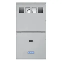
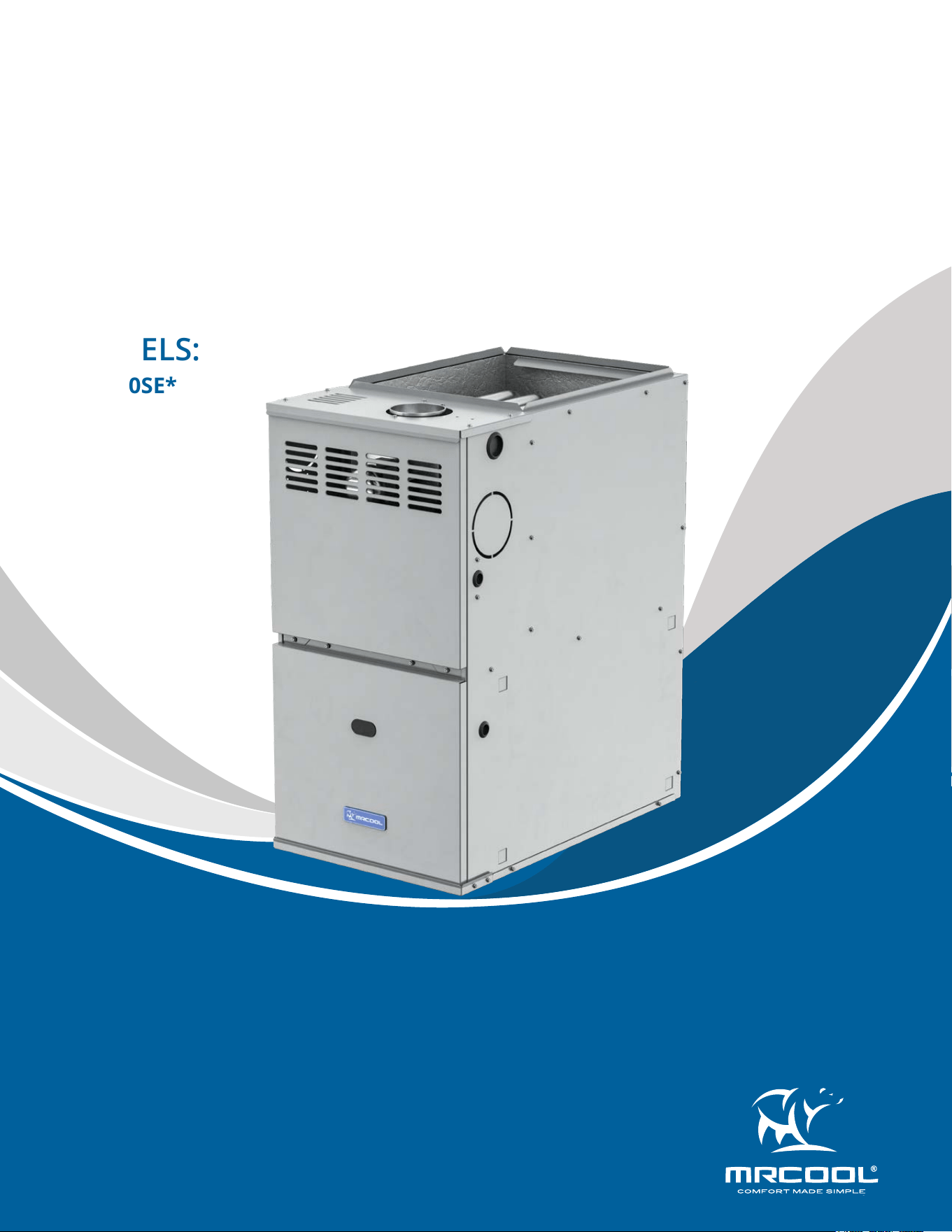
VersaPro™
80% Gas Furnace
Installation Manual
MODELS:
Read this manual carefully before installation and keep it where
the operator can easily nd it for future reference.
Due to updates and constantly improving performance, the
information and instructions within this manual are subject to
change without notice.
Version Date: August 21, 2025
Please visit www.mrcool.com/documentation
to ensure you have the latest version of this manual.
MGA80SE*

mrcool.com1
CONTENTS
SAFETY ..............................................................................................................................................2
UNIT OVERVIEW ...............................................................................................................................6
2.1 Dimensions .........................................................................................................................6
2.2 Unit Description ................................................................................................................7
2.3 Code Requirements ...........................................................................................................7
2.4 Electrostatic Discharge Precaution Procedure ..............................................................8
INSTALLATION .................................................................................................................................9
3.1 Location Selection ..............................................................................................................9
3.2 Upow Installation ..........................................................................................................11
3.3 Downow Installation .....................................................................................................11
3.4 Horizontal Installation ....................................................................................................15
3.5 Filter Arrangement ..........................................................................................................16
3.6 Air Ducts ............................................................................................................................17
VENTING .........................................................................................................................................19
4.1 Vent Connections .............................................................................................................19
4.2 Venting System Requirements .......................................................................................20
4.3 Venting into an Existing Chimney ..................................................................................20
4.4 Air for Combustion & Ventilation ..................................................................................20
4.5 Air Supply Openings & Ducts ..........................................................................................22
4.6 Ventilated Combustion Air .............................................................................................22
4.7 Safety Check Procedure ..................................................................................................22
GAS SUPPLY & PIPING ...................................................................................................................23
5.1 General Overview ............................................................................................................23
5.2 High Altitude Derate ........................................................................................................24
5.3 Propane Gas Conversion .................................................................................................25
5.4 Gas Piping Connections...................................................................................................26
5.5 Gas Piping Checks ............................................................................................................27
ELECTRICAL CONNECTIONS ..........................................................................................................28
6.1 115V Wiring .......................................................................................................................28
6.2 Electrical Connection to J-Box ........................................................................................29
6.3 Power Cord Installation to J-Box ....................................................................................30
6.4 Bx Cable Installation to J-Box .........................................................................................30
6.5 24-V Wiring ........................................................................................................................31
6.6 Accessories (Field Supplied)............................................................................................31
6.7 Grounding .........................................................................................................................31
6.8 Furnace Control Diagram................................................................................................31
6.9 Wiring Diagram with I-Stage Thermostat .....................................................................32
6.10 Refrigerant Leakage Sensor Requirements .................................................................32
START-UP, ADJUSTMENT, & SAFETY CHECK .................................................................................34
7.1 General Overview ............................................................................................................34
7.2 Start-Up Procedures ........................................................................................................34
7.3 Furnace Start-up ..............................................................................................................35
7.4 Sequence of Operation ...................................................................................................35
7.5 Gas Manifold Pressure Measurement & Adjustment .................................................37
7.6 Gas Input Rate Measurement (Natural Gas Only) .......................................................38
7.7 Temperature Rise Adjustment .......................................................................................39
7.8 Circulator Blower Speed Adjustment ............................................................................39
1
Contents
2
3
4
5
6
7
mrcool.com 2 2
Contents
OPERATIONAL CHECKS ..................................................................................................................40
8.1 Burner Flame ....................................................................................................................40
SAFETY CIRCUITS ............................................................................................................................41
9.1 General ..............................................................................................................................41
9.2 Integrated Control Module .............................................................................................41
9.3 Primary Limit ....................................................................................................................41
9.4 Reverse Flow Switch ........................................................................................................41
9.5 Rollout Limits ...................................................................................................................41
9.6 Pressure Switches ............................................................................................................41
9.7 Flame Sensor ....................................................................................................................41
TROUBLESHOOTING ......................................................................................................................42
10.1 Electrostatic Discharge (Eso) Precautions ...................................................................42
10.2 Diagnostic Chart .............................................................................................................42
10.3 Resetting from Lockout .................................................................................................42
SERVICE & MAINTENANCE PROCEDURES ....................................................................................44
11.1 Annual Inspection ..........................................................................................................44
11.2 Filters ...............................................................................................................................44
11.3 Induced Draft & Circulating Blower Motors ...............................................................45
11.4 Flame Sensor ..................................................................................................................45
11.5 Burners ...........................................................................................................................45
11.6 Cleaning Heat Exchanger ..............................................................................................46
11.7 Before Leaving an Installation .....................................................................................48
11.8 Repair & Replacement Parts ........................................................................................48
11.9 Wiring Diagrams ............................................................................................................49
CONTENTS, CONTD.
10
11
NOTE
Indicates suggestions which will result in enhanced
installation, reliability, or operation.
Incorrect usage may cause serious damage or injury.
The symbols below are used throughout this manual to indicate instructions that should be followed closely
or actions that should be avoided to prevent death, injury, and/or property damage.
Safety Precautions
CAUTION
Indicates the possibility of personal injury or loss of life.
Indicates the possibility of property damage or serious
consequences.
Read Before Using
WARNING
GENERAL WARNINGS FOR SAFETY
1. Improper installation, adjustment, alteration, service, maintenance, or use could cause carbon monoxide
poisoning, explosion, re, electrical shock, or other conditions which may cause personal injury or property
damage. Consult a qualied service agency, local gas supplier, or MRCOOL
®
for information or assistance.
The qualied service agency must use only factory-authorized and listed kits or accessories when
modifying this product.
8
9
mrcool.com3
SAFETY
1
CAUTION: LOCATION SELECTION
1. Only use this unit in well-ventilated spaces and ensure that there are no obstructions that could impede
the airow into and out of the unit.
Do not use this unit in the following locations:
• Locations with mineral oil, saline atmospheres (such as seaside locations), sulfurous
atmospheres (such as near natural hot springs)
• Where high voltage electricity is present, such as in certain industrial locations.
• On vehicles or vessels, such as trucks or ferry boats.
• Where exposure to oily or very humid air may occur, such as kitchens.
• In proximity to sources of electromagnetic radiation, such as high-frequency transmitters or
other high-strength radiation devices.
2. The unit is CSA (formerly A.G.A. and C.G.A.) design-certied for use with natural and propane gases (see
furnace rating plate) and for installation in alcoves, attics, basements, closets, utility rooms, crawlspaces,
and garages. The furnace is factory-shipped for use with natural gas. A CSA-listed accessory gas conversion
kit is required to convert furnace for use with propane gas.
3. The furnaces must be kept free and clear of insulating materials. Inspect the surrounding area to ensure
insulation material is in safe distance when installing furnace or adding insulation materials. Insulation
materials may be combustible. Maintain a 1 in. (25mm) clearance from combustible materials to supply air
ductwork for a distance of 36 in. (914mm) horizontally from the furnace. See NFPA 90B or local code for
further requirements.
4. The furnace should not be installed directly on carpeting, tile, or any other combustible material other
than wood ooring. In downow installations, factory accessory oor base must be used when installed on
combustible materials and wood ooring. Special base is not required when installed on manufacturer's
coil assembly.
5. Furnace operation needs air for combustion and ventilation. Do not block or obstruct air openings on
furnace or spacing around furnace required for supplying sucient combustion air and ventilation.
NOTE FOR OPTIMAL OPERATION
Before heating season begins, examine the furnace to determine that:
• All ue gas carrying areas external to the furnace (i.e. chimney, vent connector) are clear and free of
obstructions.
• The vent connector is in place, slopes upward, and is physically sound without holes or excessive corrosion.
• The return-air duct connection(s) is physically sound, is sealed to the furnace casing, and terminates
outside the space containing the furnace.
• The physical support of the furnace is sound without sagging, cracks, gaps, etc. around the base so as to
provide a seal between the support and the base.
• There are no obvious signs of deterioration of the furnace.
• The burner ames are adjusted appropriately.
GENERAL WARNINGS FOR SAFETY
2. Should the gas supply fail to shut o or if overheating occurs, shut o the gas valve to the furnace before
shutting o the electrical supply.
3. Never test for gas leaks with an open ame. Use a commercially available soap solution made specically
for the detection of leaks to check all connections, as specied in the "Gas Supply and Piping" section.
WARNING: FIRE OR EXPLOSION HAZARD
The furnace is designed and approved for use with Natural Gas and (LP) Propane gas ONLY. DO NOT BURN
ANY LIQUID OR SOLID FUEL IN THIS FURNACE.
Burning any unapproved fuel will result in damage to the furnace heat exchanger, which could result in re,
personal injury, and/or property damage.

mrcool.com 4
4
SAFETY
1
GENERAL CAUTIONS FOR SAFETY
• Follow all safety codes. Consult local building codes, the current editions of the National Fuel Gas Code
(NFGC) NFPA 54/ANSI Z223.1 and the National Electrical Code (NEC) NFPA 70. In Canada, refer to the
current editions of the National Standards of Canada CAN/CSA-BI49.1 and .2 Natural Gas and Propane
Installation Codes, and Canadian Electrical Code CSA C22.1.
• Wear safety glasses, protective clothing, and work gloves.
• Have a re extinguisher available.
• Read these instructions thoroughly as well as those attached to the unit.
• Improper installation or misapplication of furnace may require excessive servicing or cause premature
component failure. Application of this furnace should be indoors with special attention given to vent sizing
and material, gas input rate, air temperature rise, unit leveling, and unit sizing.
• Combustion products must be discharged outdoors. Connect this furnace to an approved vent system
only, as specied in the "Venting" section of this manual.
• Always install furnace to operate within the furnace's intended temperature-rise range with a duct system
which has an external static pressure within the allowable range, as specied in the "Start-Up, Adjustments,
and Safety Check" section. Also see the furnace rating plate.
• When a furnace is installed so that supply ducts carry air circulated by the furnace to areas outside the
space containing the furnace, the return air shall also be handled by duct(s) sealed to the furnace casing
and terminating outside the space containing the furnace. See "Air Ducts" section.
• A gas-red furnace for installation in a residential garage must be installed as specied in the "Caution:
Location Selection" box.
• The furnace may be used for construction heat provided that the furnace installation and operation
complies with the requirements in the "Caution: Location Selection" box.
• This furnace must be installed in accordance with these instructions and local codes. In the absence of
local codes, follow the National Fuel Gas Code ANSI Z223.1/NFPA54 or CSA B-149.1 Gas Installation Code.
• This furnace must be installed so there are provisions for combustion and ventilated air.
• This furnace is equipped with manual reset limit switch(es) in the burner compartment to protect against
overheating that can result from inadequate combustion air supply or blocked vent conditions. Do not
bypass the limit switches. If a limit opens, call a qualied technician to correct the condition and reset the
limit switch.
• An accessory kit, supplied by the manufacturer, can be used to convert to propane gas use or may be
required for some natural gas applications.
• The furnace is for indoor installation in a building constructed on site.
• This furnace may be installed on combustible ooring in an alcove or closet at the minimum clearance
indicated by the diagram.
• This furnace may be used with a Type B-1 Vent and may be vented in common with other gas-red
appliances.
mrcool.com5
SAFETY
1
FOR YOUR SAFETY, READ BEFORE OPERATING.
WARNING: If these instructions are not followed exactly, it may result in a re or explosion causing property
damage, personal injury, or loss of life.
A. This appliance does not have a pilot. It is equipped with an ignition device which automatically lights the
burner. DO NOT try to light the burner by hand.
B. Before operating, smell all around the appliance area for gas. Be sure to smell next to the oor as some gas
is heaver than air and will settle on the oor.
What to do if you smell gas:
• Do not try to light any appliance.
• Do not touch any electrical switch; do not use a phone inside the building.
• Immediately call your gas supplier from a phone outside of the building. Follow the gas supplier's
instructions.
• If you cannot reach your gas supplier, call the re department.
C. Use only your hand to turn the gas control switch. Never use tools. If the switch will not turn by hand, do not
try to repair it; call a qualied service technician. Force or attempted repair may result in a re or explosion.
D. Do not use this appliance if any part has been under water. Immediately call a qualied service technician
to inspect the appliance and to replace any part of the control system and any gas control which has been
under water.
OPERATING INSTRUCTIONS:
1. STOP! Read the safety information above on this label.
2. Set the thermostat to lowest setting.
3. Turn o all electric power to the appliance.
4. This appliance is equipped with an ignition device which automatically lights the burner. Do not try to light
the burner by hand.
5. Remove control access panel.
6. Wait ve (5) minutes to clear out any gas. If you smell gas, STOP. Follow "B" in the safety information above.
If you don't smell gas, go to the next step.
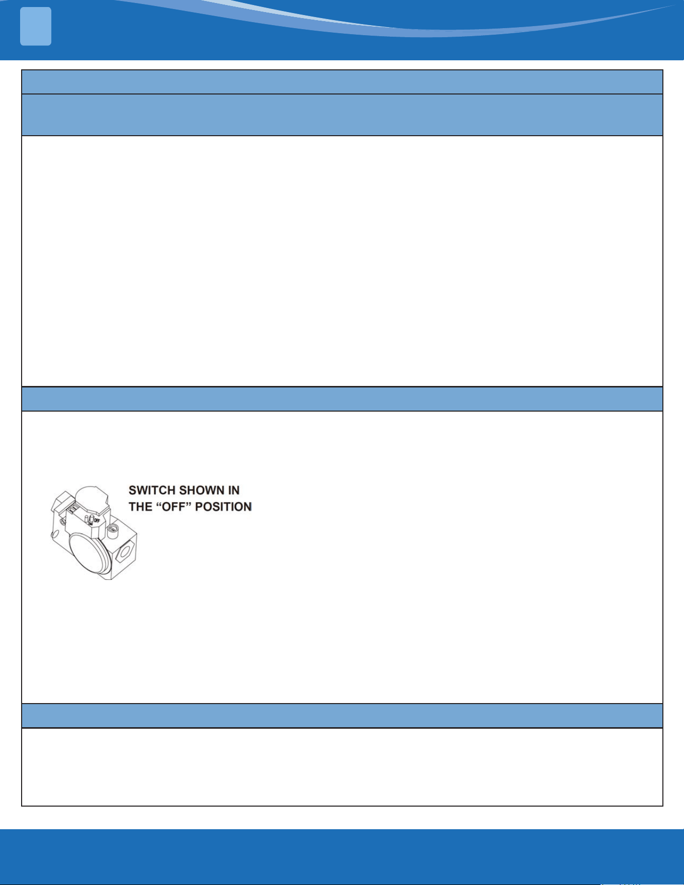
7. Push gas control switch to "ON". Do not force.
8. Replace control access panel.
9. Turn on all electric power to the appliance.
10. Set the thermostat to the desired setting.
11. If the appliance will not operate, follow the instructions below regarding turning o the gas to the
appliance and call your service technician or gas supplier.
TURNING OFF GAS TO APPLIANCE
1. Set the thermostat to its lowest setting.
2. Turn o all electric power to the appliance if service is to be performed.
3. Remove control access panel.
4. Push gas control to "OFF". Do not force.
5. Replace control access panel.
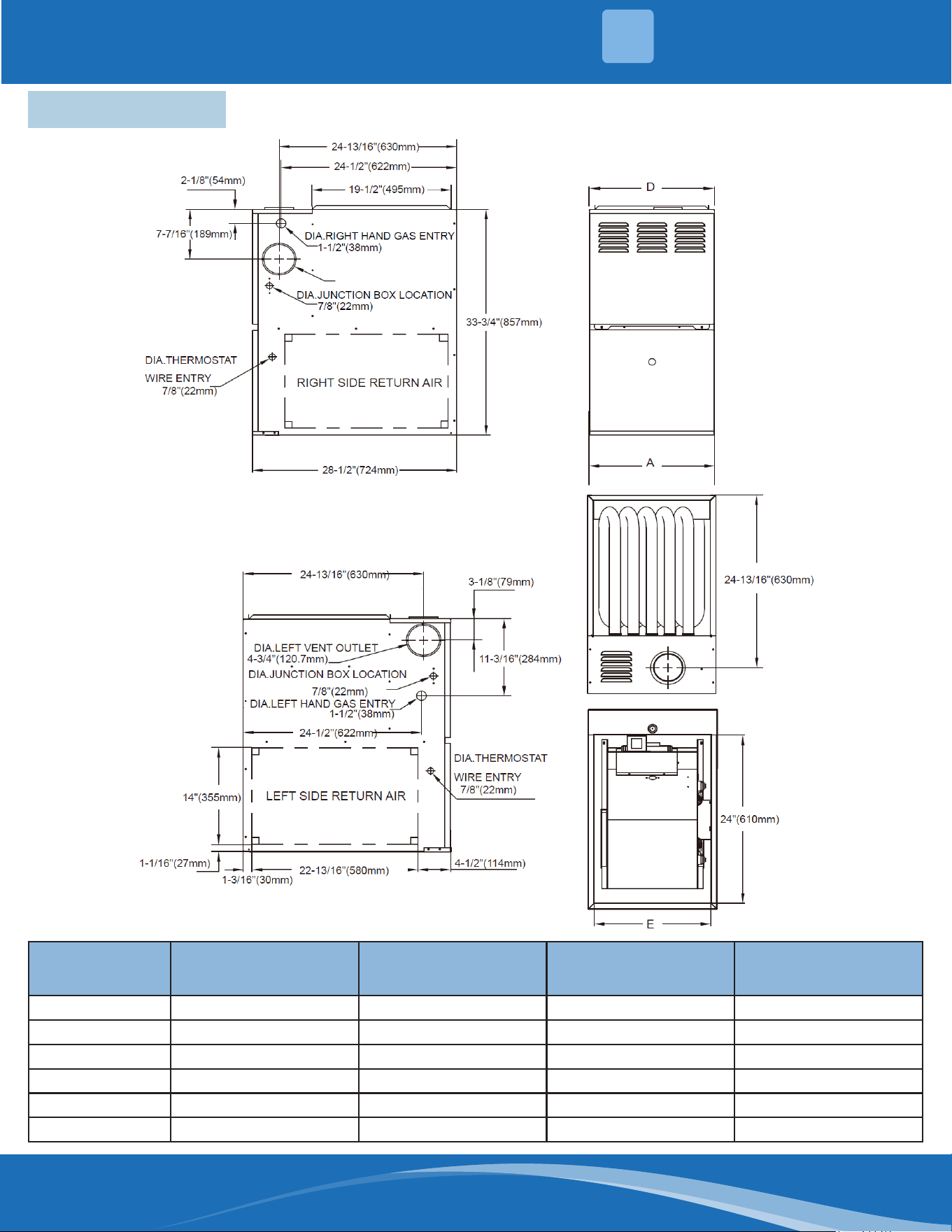
mrcool.com 6
6
UNIT OVERVIEW
2
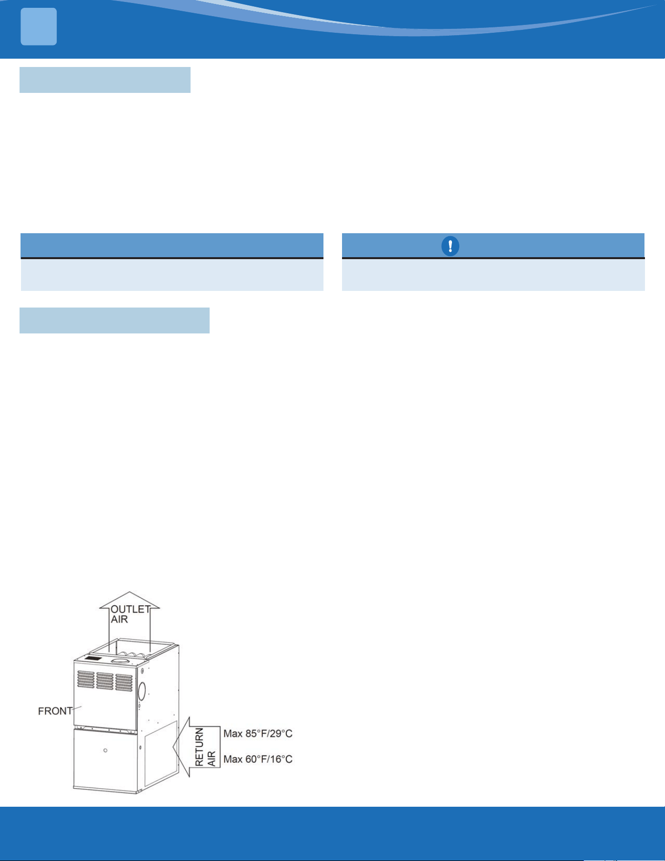
2.1 Dimensions
Furnace Size
A
Cabinet Width
in. (mm)
D
Supply Air Width
in. (mm)
E
Return Air Width
in. (mm)
Ship Weight (lbs)
MGA80SE040A3C 14.5 (368) 13 (330) 15-57/32 (326) 132
MGA80SE060B4C 17.5 (446) 16 (406) 15-27/32 (402) 141
MGA80SE080B4C 17.5 (446) 16 (406) 15-27/32 (402) 155
MGA80SE080C4C 21 (533) 19.5 (495) 19-13/32 (493) 163
MGA80SE100C5C 21 (533) 19.5 (495) 19-13/32 (493) 177
MGA80SE120D5C 24.5 (622) 23 (584) 22-27/32 (580) 190
Table 2.1
mrcool.com7
CAUTION
Check the entire gas assembly for leaks after lighting
this appliance.
2.2 Unit Description
Safety
UNIT OVERVIEW
2
This 4-way multipurpose Category I fan-assisted furnace is CSA design-certied. A Category I fan-assisted furnace
is an appliance equipped with an integrated mechanical means to either draw or force products of combustion
through the combustion chamber and/or heat exchanger. The furnace is factory-shipped for use with natural gas.
This furnace is not approved for installation in mobile homes, recreational vehicles, or outdoors. The unit is
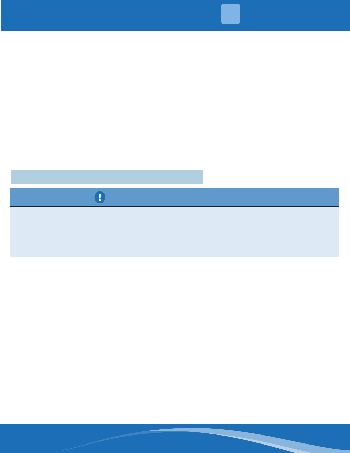
designed for a minimum continuous return-air temperature of 60°F (16°C) or intermittent operations down to
55°F (13°C) such as when used with a night setback thermostat. Return-air temperatures must not exceed 85°F
(29°C). Failure to follow these return-air temperature limits may aect reliability of heat exchangers, motors, and
controls.
For accessory installation details, refer to its accompanying instruction literature.
2.3 Code Requirements
Follow all national and local codes and standards in
addition to these instructions. The installation must
comply with regulations of the serving gas supplier,
local building, heating, plumbing, and other codes. In
absence of local codes, the installation must comply
with the national codes listed below and all authorities
having jurisdiction. In the United States and Canada,
follow all codes and standards for the following:
• USA: National Fuel Gas Code (NFGC) NFPA 54-2006/
ANSI Z223.1-2006 and the Installation Standards,
Warm Air Heating and Air Conditioning Systems
ANSI/NFPA 90B
• CANADA: CSA B149.1-05 National Standard of
Canada Natural Gas and Propane Installation Codes
(CAN/CSA-B149.1-05)
NOTE
Remove all shipping brackets and materials before
operating the furnace.
General Installation
• USA: Current edition of the NFGC and the NFPA
90B. For copies, contact the National Fire Protection
Association Inc., Batterymarch Park, Quincy, MA
02269; (www.NFPA.org) or for only the NFGC,
contact the American Gas Association, 400 N.
Capitol Street, N.W., Washington, DC 20001 (www.
AGA.org).
• CANADA: CAN/CSA-B149.1-05. For a copy, contact
Standard Sales, CSA International, 178 Rexdale
Boulevard, Etobicoke (Toronto), Ontario, M9W 1R3
Canada.
Combustion & Ventilation Air
• US: Section 9.3 of the NFGC, NFPA 54/ANSI Z223.1-
2006 Air for Combustion and Ventilation.
• CANADA: Part 8 of CAN/CSA-B149.1-05, Venting
Systems and Air Supply for Appliances.
Duct Systems
• US and CANADA: Air Conditioning Contractors
Association (ACCA) Manual D, Sheet Metal and Air
Conditioning Contractors National Association
(SMACNA), or American Society of Heating,
Refrigeration, and Air Conditioning Engineers
(ASHRAE) 2001 Fundamentals Handbook Chapter
34 or 2000 HVAC Systems and Equipment Handbook
Chapters 9 and 16.
mrcool.com 8
8
UNIT OVERVIEW
2
Acoustical Lining & Fibrous Glass Duct
• US and CANADA: current edition of SMACNA and
NFPA 90B as tested by UL Standard 181 for Class I
Rigid Air Ducts.
Gas Piping & Gas Pipe Pressure Testing
• US: NFPA 54/ANSI Z223.1-2006 Chapters 5,6, 7, and
8 and National Plumbing Codes.
• CANADA: CAN/CSA-B149.1-05 Parts 4, 5, and 6 and
Appendices A, B, E, and H.
Electrical Connections
• US: National Electrical Code (NEC) ANSI/NFPA 70-
2008.
• CANADA: Canadian Electrical Code CSA C22.I.
Electrical Power Supply
• Voltage: ANSI C84.1-2006 (104-127 volt)
Venting
• US: NFGC NFPA 54/ANSI Z223.1-2006 ; chapters 12
and 13.
• CANADA: CAN/CSA-B149.1-05 Part 8 and Appendix
C.
2.4 Electrostatic Discharge Precaution Procedure
FURNACE RELIABILITY HAZARD
• Improper installation or service of furnace may cause premature furnace component failure. Electrostatic
discharge can aect electronic components.
• Follow the Electrostatic Discharge Precautions Procedure listed below during furnace installation and
servicing to protect the furnace electronic control. Precautions will prevent electrostatic discharges from
personnel and hand tools which are held during the procedure.
• These precautions will help to avoid exposing the control to electrostatic discharge by putting the furnace,
the control, and the person at the same electrostatic potential.
• Disconnect all power to the furnace Disconnect all power to the furnace. Multiple disconnects maybe required.
DO NOT TOUCH THE CONTROL OR ANY WIRE CONNECTED TO THE CONTROL PRIOR TO DISCHARGING YOUR
BODY'S ELECTROSTATIC CHARGE TO GROUND.
• Firmly touch the clean, unpainted, metal surface of the furnace chassis which is close to the control. Tools held
in a person's hand during grounding will be satisfactorily discharged.
• After touching the chassis, you may proceed to service the control or connecting wires as long as you do
nothing to recharge your body with static electricity (for example: DO NOT move or shue your feet, do not
touch ungrounded objects, etc.).
• If you touch ungrounded objects (and recharge your body with static electricity), rmly touch a clean, unpainted
metal surface of the furnace again before touching control or wires.
• Use this procedure for installed and un-installed (ungrounded) furnaces.
• Before removing a new control from its container, discharge your body's electrostatic charge to ground to
protect the control from damage. If the control is to be installed in a furnace, follow items 1 through 4 before
bringing the control or yourself in contact with the furnace. Put all used and new controls into containers
before touching ungrounded objects.
• An ESD service kit (available from commercial sources) may also be used to prevent ESD damage.
mrcool.com9
INSTALLATION
3
The following types of furnace installations may require outdoor air for combustion due to chemical exposures:
• Commercial buildings
• Buildings with indoor pools
• Laundry rooms
• Hobby or craft rooms
• Chemical storage areas
CARBON MONOXIDE POISONING HAZARD
Corrosive or contaminated air may cause failure of parts containing ue gas, which could leak into the living
space. Air for combustion must not be contaminated by halogen compounds, which include uoride, chloride,
bromide, and iodide. These elements can corrode heat exchangers and shorten furnace life. Air contaminants
are found in aerosol sprays, detergents, bleaches, cleaning solvents, salts, air fresheners, and other household
products. Do not install furnace in a corrosive or contaminated atmosphere. Make sure all combustion and
circulating air requirements are met, in addition to all local codes and ordinances.
3.1 Location Selection
General
This multipurpose furnace is shipped in a packaged conguration. Some assembly and modications are required
when used in any of the four applications. This furnace must:
• Be installed so the electrical components are protected from water.
• Not to be installed directly on any combustible material other than wood ooring.
• Downow installation and horizontal installation in attics have additional requirements.
• Be located as close to the chimney or vent and attached to an air distribution system.
• Be provided ample space for servicing and cleaning. Always comply with minimum re protection clearances
shown on the furnace clearance to combustible label.
If air is exposed to the following substances, it should
not be used for combustion air, and outdoor air may be
required for combustion:
• Permanent wave solutions
• Chlorinated waxes and cleaners
• Chlorine-based swimming pool chemicals
• Water softening chemicals
• De-icing salts or chemicals
• Carbon tetrachloride
• Halogen-type refrigerants
• Cleaning solvents (such as perchloroethylene)
• Printing inks, paint removers, varnishes, etc.
• Hydrochloric acid
• Cements and glues
• Anti-static fabric softeners for clothing dryers
• Masonry acid washing materials
All fuel-burning equipment must be supplied with air for fuel combustion. Sucient air must be provided to avoid
negative pressure in the equipment room or space. A positive seal must be made between the furnace cabinet
and the return-air duct to prevent pulling air from the burner area and from draft safeguard opening.
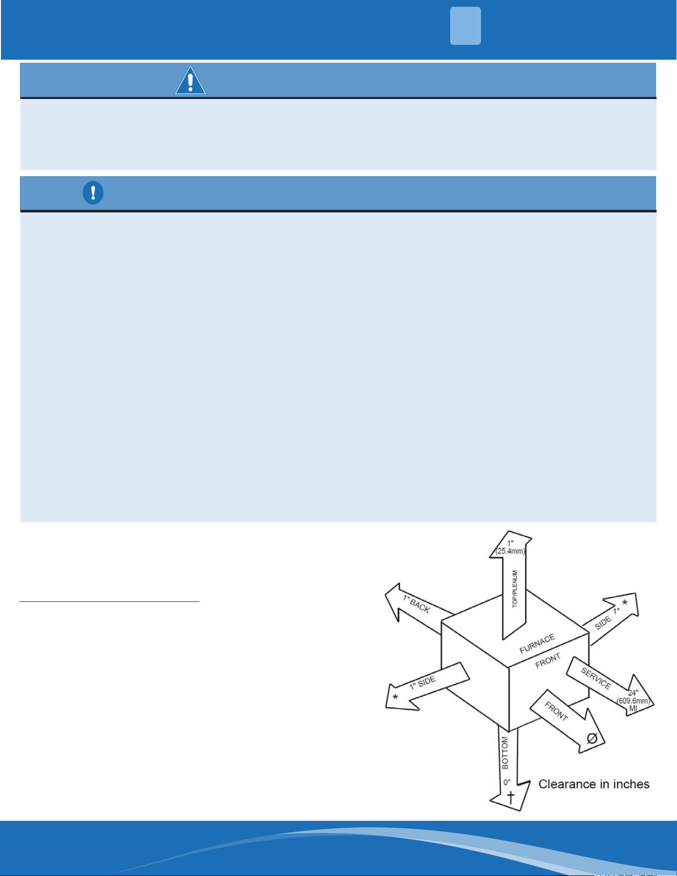
mrcool.com 10
10
INSTALLATION
3
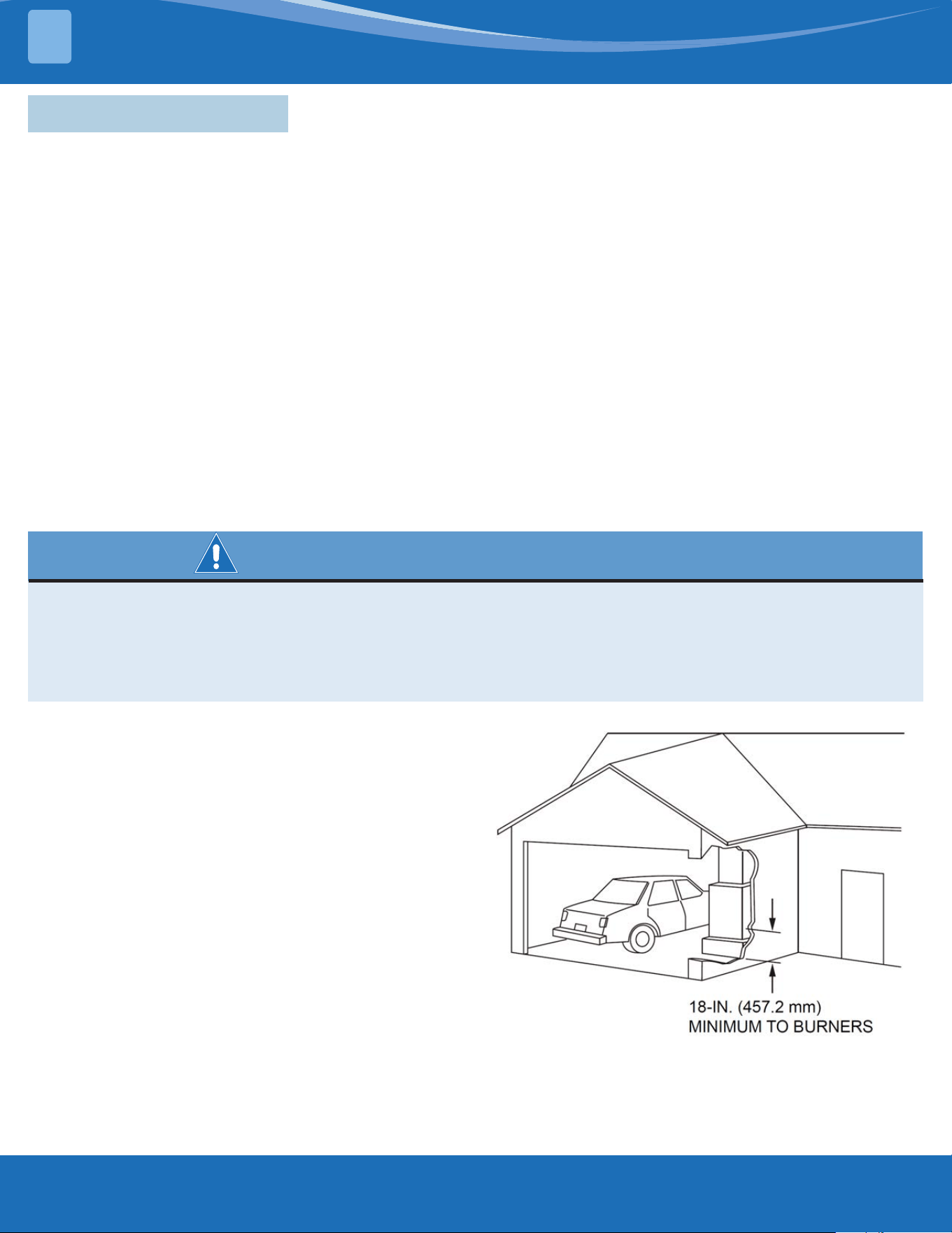
FIRE, INJURY, OR DEATH HAZARD
Failure to follow this warning could result in personal injury, death, and/or property damage. When the
furnace is installed in a residential garage, the burners and ignition sources must be located at least 18 inches
(457 mm) above the oor. The furnace must be located or protected to avoid damage by vehicles. When the
furnace is installed in a public garage, airplane hangar, or other building having a hazardous atmosphere, the
furnace must be installed in accordance with the NFGC or CAN/CSA - B149 .1-05.
PERSONAL INJURY AND/OR PROPERTY DAMAGE HAZARD
Improper use or installation of this furnace may cause premature furnace component failure. This gas furnace
may be used for heating buildings under construction provided that:
• The furnace is permanently installed with all electrical wiring, piping, venting and ducting installed
according to these installation instructions. A return air duct is provided, sealed to the furnace casing,
and terminated outside the space containing the furnace. This prevents a negative pressure condition as
created by the circulating air blower, causing a ame rollout and/or drawing combustion products into the
structure.
• The furnace is controlled by a thermostat. It may not be "hot wired" to provide heat continuously to the
structure without thermostatic control.
• Clean outside air is provided for combustion. This is to minimize the corrosive eects of adhesives, sealers
and other construction materials. It also prevents the entrainment of drywall dust into combustion air,
which can cause fouling and plugging of furnace components.
• The temperature of the return air to the furnace is maintained between 60°F (16°C) and 85°F (29°C),
with no evening setback or shutdown. The use of the furnace while the structure is under construction is
deemed to be intermittent operation per our installation instructions.
• The air temperature rise is within the rated rise range on the furnace rating plate, and the gas input rate
has been set to the nameplate value.
• The lters used to clean the circulating air during the construction process must be either changed or
thoroughly cleaned prior to occupancy.
• The furnace, ductwork, and lters are cleaned as necessary to remove drywall dust and construction debris
from all HVAC system components after construction is completed.
• Verify proper furnace operating conditions including ignition, gas input rate, air temperature rise, and
venting according to these installation instructions.
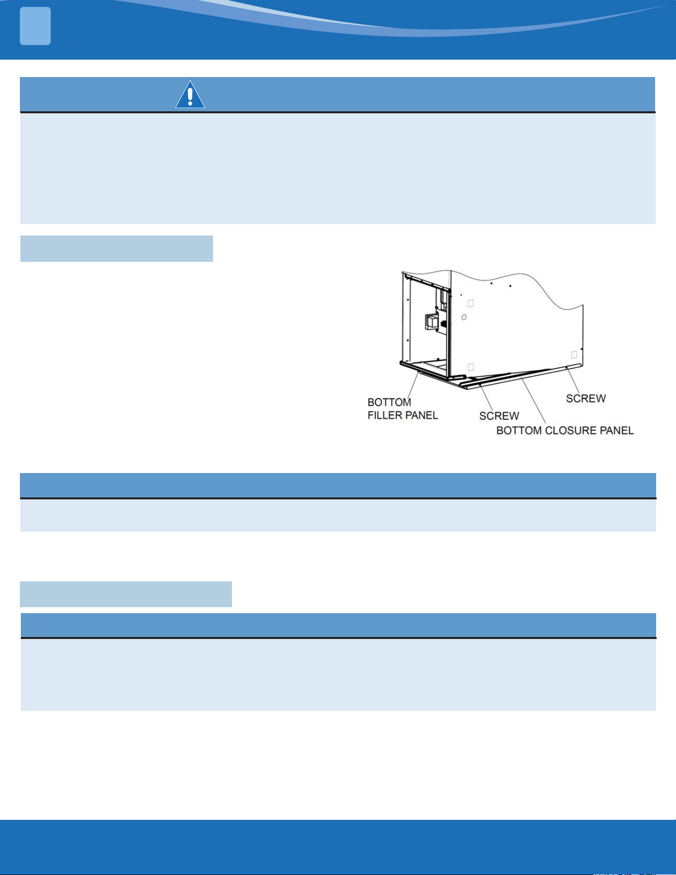
Clearance Requirements
Vent clearance to combustibles:
For single wall vents: 6 inches
For Type B-1 vent type: 1 inch
Downow Positions:
† Installation on non-combustible oors only.
-For installation on combustible ooring only when installed on
sub-base provided by installer or manufacturer.
Ø 18 inches (457.2mm) front clearance required for alcove.
Horizontal Installation in an Attic:
• Indicated supply or return sides when furnace is in the horizontal position.
Line contact only permissible between lines formed by intersections of the
top and two sides of the furnace jacket, building joists, studs, and framing.
• A special base is required.
The furnace is approved for upow, downow, and horizontal installations.
The clearance arrows do not change with furnace orientation.
mrcool.com11
INDOOR UNIT INSTALLATION
3
FIRE, INJURY, OR DEATH HAZARD
• Check the power supply before installation. Ensure that the power supply must be reliably grounded
following local, state, and National Electrical Codes. If not, for example, if the ground wire is detected
charged, installation is prohibited before it is corrected. Otherwise, there is a risk of re and electric shock,
causing physical injury or death.
• Check the electric wire, water, and gas pipeline layout inside the wall, oor, and ceiling before installation.
Do not implement drilling unless safety is conrmed, especially for the hidden power wire. An electro-
probe can be used to test whether a wire is passing by at the drilling location, to prevent physical injury or
death caused by insulation broken cords.
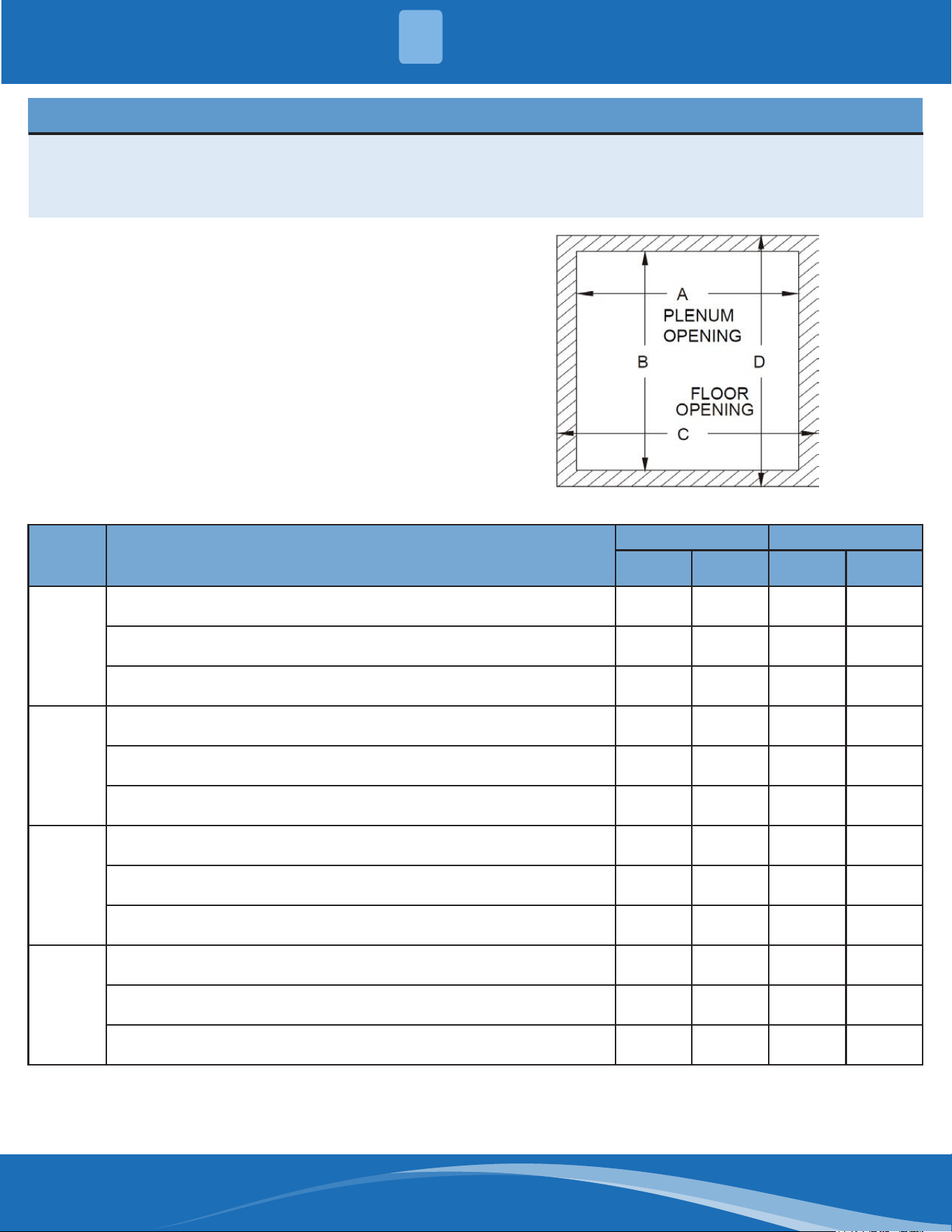
3.2 Upow Installation
Bottom Return Air Inlet
The furnace is shipped with its bottom closure panel
installed in the bottom return-air opening. Remove and
discard this panel when bottom return air is used. To
remove bottom closure panel, perform the following:
1. Tilt or raise the furnace and remove the screw
holding the bottom ller panel.
2. Remove the bottom closure panel.
Side Return Air Inlet
The furnace is shipped with its bottom closure panel
installed in the bottom return-air opening. This panel
MUST be in place when only side-return air is used.
NOTE
Side return-air openings can be used in UPFLOW and most HORIZONTAL congurations. Do not use side
return-air openings in DOWNFLOW conguration.
3.3 Downow Installation
NOTE
For downow applications, this furnace is approved for use on combustible ooring when any one of the
following 3 accessories are used:
• Special Base
• Cased Coil Assembly
• Coil Box
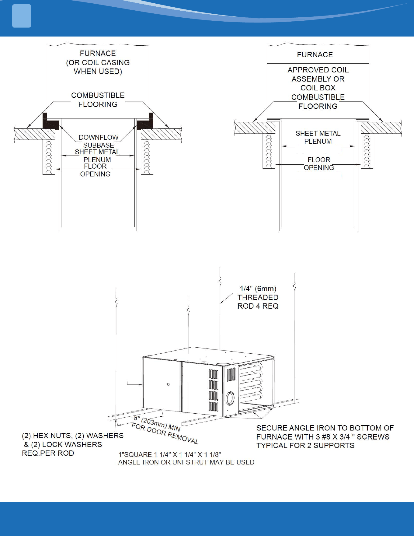
1. Determine the application being installed from Table 3.3.
2. Construct a hole in the oor according to requirements in Table 3.3 and Figure 3.3a.
3. Construct plenum to dimensions specied in Table 3.3 and Figure 3.3a.
4. If a downow subbase is used, install as shown in Figure 3.3b. If Coil Assembly or Coil Box is used, install as
shown in Figure 3.3c.
Figure 3.2
mrcool.com 12
12
INDOOR UNIT INSTALLATION
3
NOTE
• It is recommended that the supply-air duct anges be completely folded over or removed from the furnace
when installing the furnace on a factory-supplied cased coil or coil box.
• To remove the supply-air duct ange, use wide-duct pliers or hand seamers to bend ange. Be careful of
sharp edges.
Bottom Return Air Inlet
Do not use side return openings in a downow
conguration.
The furnace is shipped with its bottom closure panel
installed in the bottom return-air opening. Remove
and discard this panel when bottom return air is used.
See Figure 3.2 for bottom closure removal.
Figure 3.3a
Furnace
Casing
Width
Application
Plenum Opening Floor Opening
A B C D
14-1/2
(368)
Downow Applications on Noncombustible Flooring
13-3/16
(335)
16-11/16
(424)
13-13/16
(351)
17-21/64
(440)
Downow Applications on Combustible Flooring Using Special Base
12-11/64
(309)
16-1/32
(407)
12-63/64
(330)
16-13/16
(427)
Downow Applications on Combustible Flooring with Manufacturer
Supplied Coil Assembly or Coil Box
13-3/16
(335)
16-3/16
(411)
13-13/16
(351)
16-13/16
(427)
17-1/2
(445)
Downow Applications on Noncombustible Flooring
16-3/16
(411)
19-11/16
(500)
16-13/16
(427)
20-5/16
(516)
Downow Applications on Combustible Flooring Using Special Base
15-3/16
(385)
19 (483) 16 (406)
19-3/4
(503)
Downow Applications on Combustible Flooring with Manufacturer
Supplied Coil Assembly or Coil Box
16-3/16
(411)
19-3/16
(487)
16-13/16
(427)
19-13/16
(503)
21
(553)
Downow Applications on Noncombustible Flooring
19-11/16
(500)
19-11/16
(500)
20-5/16
(516)
20-5/16
(516)
Downow Applications on Combustible Flooring Using Special Base
18-11/16
(474)
19 (483)
19-1/2
(495)
19-3/4
(503)
Downow Applications on Combustible Flooring with Manufacturer
Supplied Coil Assembly or Coil Box
19-11/16
(500)
19-3/16
(487)
20-5/16
(516)
19-13/16
(503)
24-1/2
(622)
Downow Applications on Noncombustible Flooring
23-3/16
(589)
19-11/16
(500)
23-13/16
(605)
20-5/16
(516)
Downow Applications on Combustible Flooring Using Special Base
22-3/16
(563)
19 (483) 23 (584)
19-3/4
(503)
Downow Applications on Combustible Flooring with Manufacturer
Supplied Coil Assembly or Coil Box
19-11/16
(500)
19-3/16
(487)
20-5/16
(516)
19-13/16
(503)
Table 3.3
mrcool.com13
INDOOR UNIT INSTALLATION
3
Figure 3.3b Figure 3.3c
Figure 3.3d
(B)
(D)
mrcool.com 14
14
INDOOR UNIT INSTALLATION
3
Figure 3.3e
Figure 3.3f
mrcool.com15
INDOOR UNIT INSTALLATION
3
3.4 Horizontal Installation
FIRE, EXPLOSION, & CARBON MONOXIDE POISONING HAZARD
• Do not install the furnace on its back or hang furnace with control compartment facing downward.
• Safety control operation will be adversely aected. Never connect return-air ducts to the back of the
furnace.
The furnace can be installed horizontally in an attic or crawl space on bottom or either the left-hand (LH) or right-
hand (RH) side. The furnace can be hung from oor joists, rafters, or trusses, or installed on a non-combustible
platform, blocks, bricks, or pad.
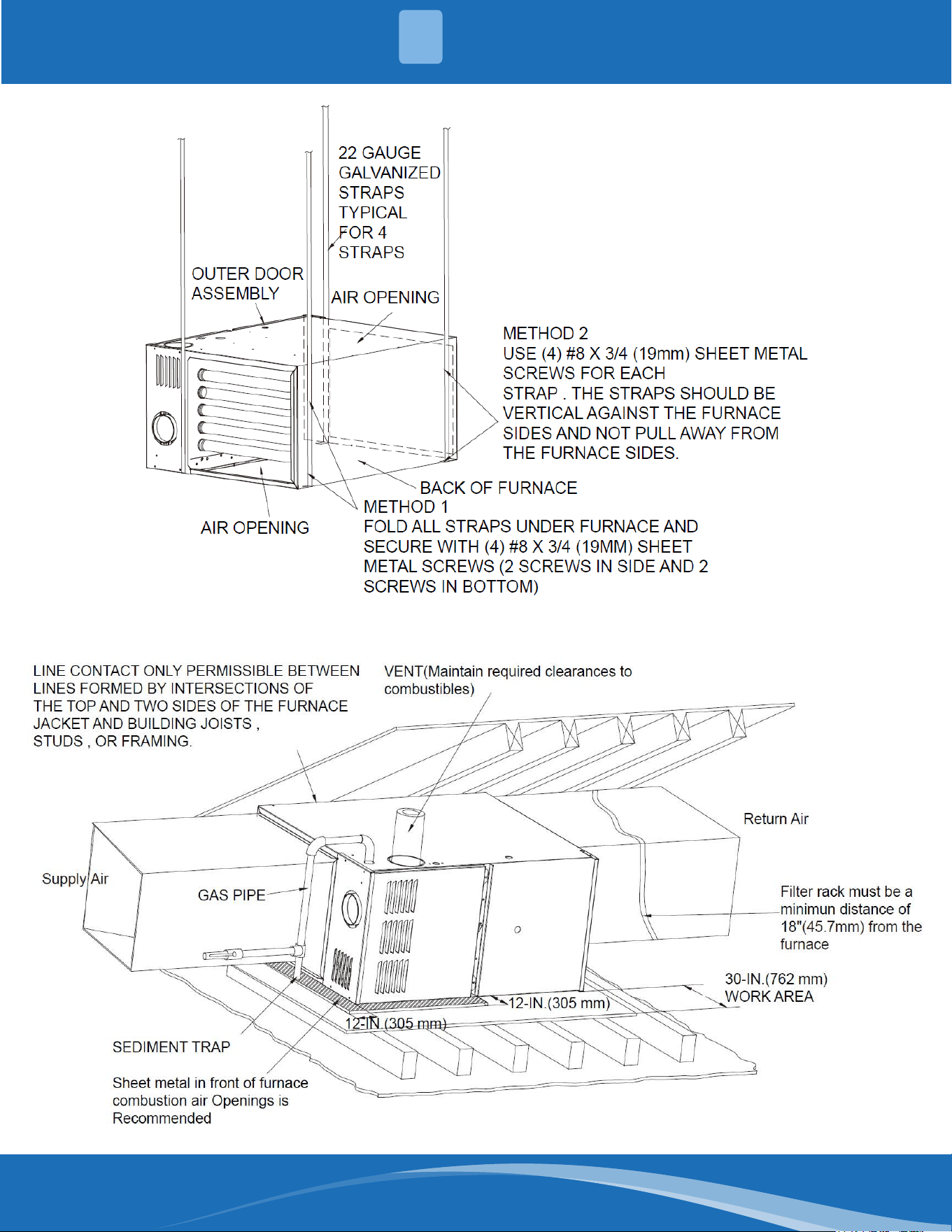
Suspended Furnace Support
The furnace may be supported under each end with threaded rod, angle iron, or metal plumber's strap as shown
in Figure 3.3d and 3.3e.
Secure angle iron to bottom of furnace as shown. Heavy-gauge sheet metal straps (plumber's straps) may be used
to suspend the furnace from each bottom corner. To prevent screws from pulling out, use 2 #8 x 3/4-in screws
into the side and 2 #8 x 3/4-in screws in the bottom of the furnace casing for each strap. (See Figure 3.3d & 3.3e)
If the screws are attached to ONLY the furnace sides and not the bottom, the straps must be vertical against the
furnace sides and not pull away from the furnace sides, so that the strap attachment screws are not in tension
(are loaded in shear) for reliable support.
Construct working platform at a location where all required furnace clearances are met. For furnaces with 1-in.
clearance requirement on the side, set furnace on noncombustible blocks, bricks, or angle iron. For crawl space
installations, if the furnace is not suspended from the oor joists, the ground underneath the furnace must be
level and the furnace set on blocks or bricks.
Roll-Out Protection
Provide a piece of sheet metal for ame roll-out protection in front of burner area for furnaces closer than 12
in. (305 mm) above the combustible deck or suspended furnaces closer than 12 in. (305 mm) to joists. The sheet
metal MUST extend underneath the furnace casing by 1 in. (25 mm) with the door removed.
The bottom closure panel on furnaces of widths 12 in (305 mm) and larger may be used for ame roll-out protection
when the bottom of the furnace is used for return air connection. See Figure 3.3 for proper orientation of roll-out
shield.
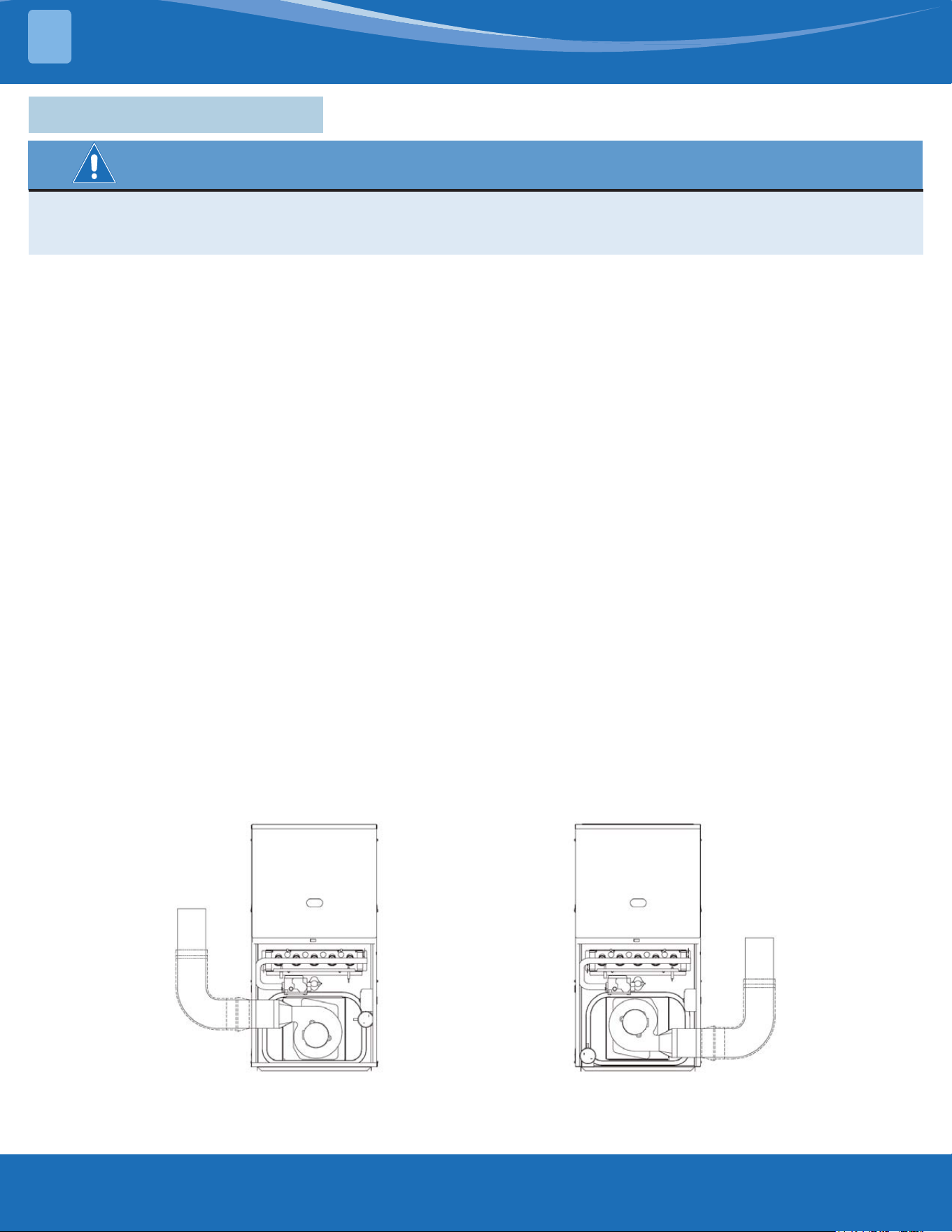
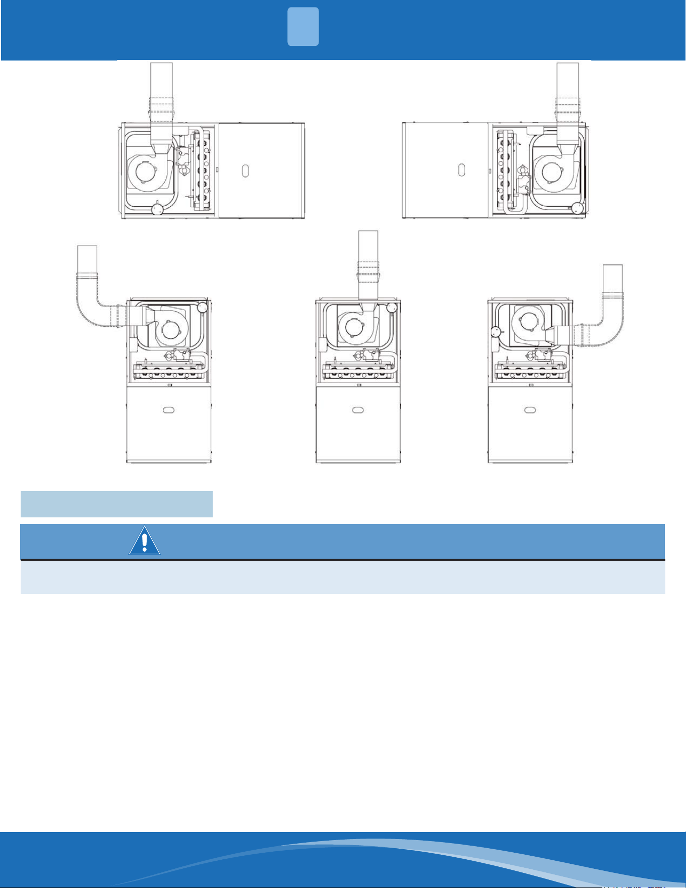
Vent the furnace with the appropriate connector as shown in Figures 3.4a-g.
Downow Application-Vent
Elbow Up then Left
Downow Application-Vent
Elbow Up then Right
Figure 3.4a Figure 3.4b
mrcool.com 16
16
INDOOR UNIT INSTALLATION
3
Horizontal Left Application-Vent Elbow Up Horizontal Right Application-Vent Elbow Up
Upow Application-Vent Elbow RightUpow Application-Vent Elbow UpUpow Application-Vent Elbow Right
Figure 3.4c
Figure 3.4d
Figure 3.4e Figure 3.4f Figure 3.4g
3.5 Filter Arrangement
CARBON MONOXIDE & POISONING HAZARD
• Failure to follow this warning could result in personal injury or death.
• Never operate a furnace without a lter or with the lter access door removed.
Filter Size
See recommended lter size and type in Table 3.6b.
One of the most common problems in furnaces is a
blocked or dirty lter. The lter must be inspected
monthly for dirt accumulation and replace it if
necessary.
Filter Type
Air velocity through throwaway lters may not
exceed 300 feet per minute (91.4m/min). All
velocities over this require the use of height velocity
lters. If a normal speed disposable lter is used
and air speed exceeds 300 feet per minute (FPM),
two side returns or one side return and the bottom
return may be needed. For airow, refer to Table
3.6a.
Side Return
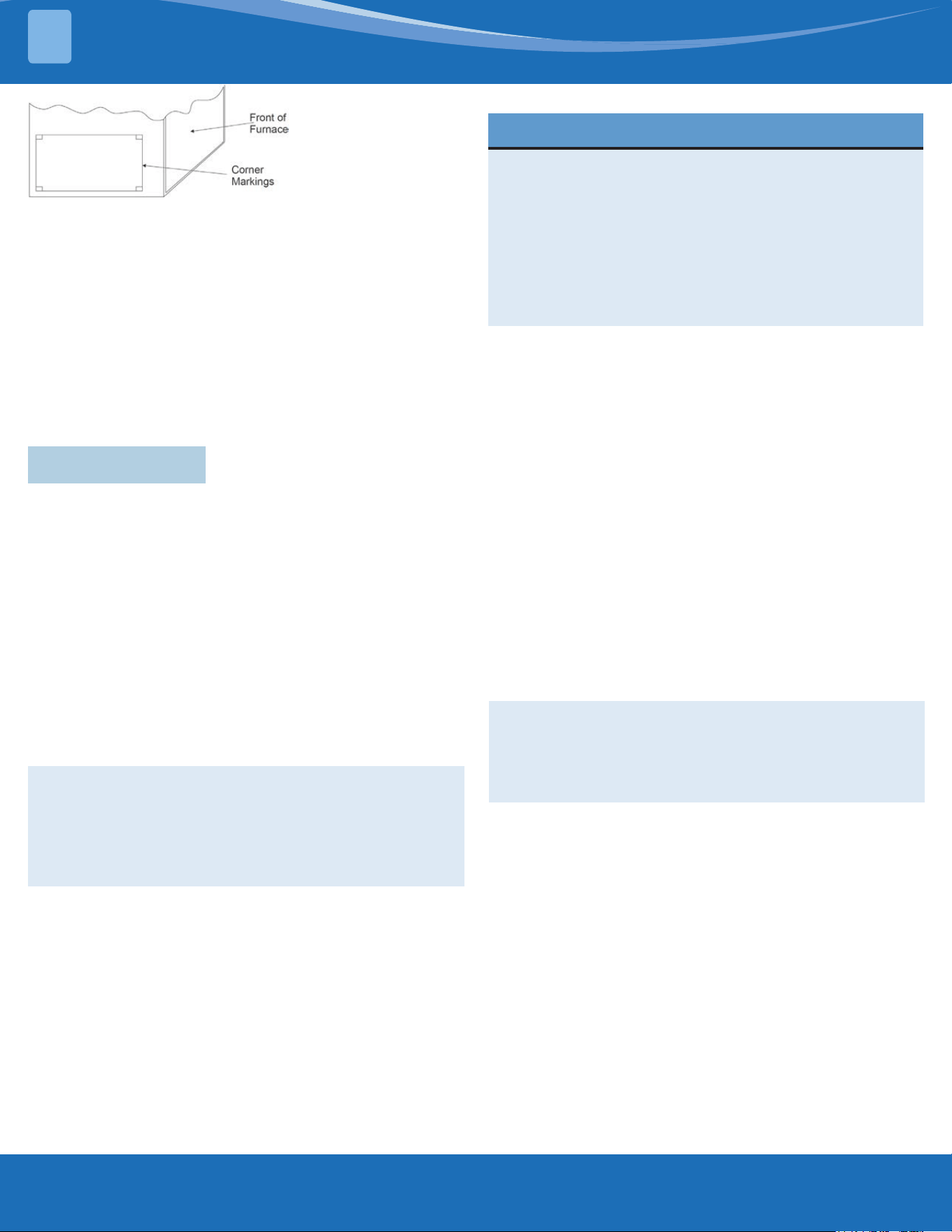
Locate the 4 cutout locations. These indicate the size of the cut-out to be made in the furnace side panel. Refer to
Figure 3.5.
Install the side lter rack following the instructions provided with the accessory. If a lter is provided at another
location in the return air system, the ductwork may be directly attached to the furnace side panel.
IMPORTANT: Some accessories such as electronic air cleaners and pleated media may require a larger side opening.
Follow the instructions supplied with that accessory for side opening instructions.
mrcool.com17
INDOOR UNIT INSTALLATION
3
Downow Filters
Downow furnaces typically are installed with the lters
located above the furnace, extending into the return air
plenum or duct. Any branch duct (rectangular or round
duct) attached to the plenum must attach to the vertical
plenum above the lter height.
Filter(s) may be located in the duct system external to
the furnace using an external duct lter box attached
to the furnace plenum or at the end of the duct in a
return lter grille. The use of straps and/or supports
is required to support the weight of the external lter
box.
3.6 Air Ducts
General Requirements
The duct system should be designed and sized
according to accepted national standards such as
those published by Air Conditioning Contractors
Association (ACCA), Sheet Metal and Air Conditioning
Contractors National Association (SMACNA) or
American Society of Heating, Refrigerating, and Air
Conditioning Engineers (ASHRAE) or consult The Air
Systems Design Guidelines reference tables available
from your local distributor. The duct system should be
sized to handle the required system design CFM at the
design external static pressure. The furnace airow
rates are provided in Table 3.6a AIR DELIVERY-CFM
(Without Filter).
NOTE: Flexible connections should be used between
ductwork and furnace to prevent transmission of
vibration. Ductwork passing through unconditioned
space should be insulated and sealed to enhance
system performance. When air conditioning is used,
a vapor barrier is recommended.
Ductwork Acoustical Treatment
For a furnace not equipped with a cooling coil, the
outlet duct shall be provided with a removable access
panel. This opening shall be accessible when the
furnace is installed and shall be of such a size that the
heat exchanger can be viewed for possible openings
using light assistance or a probe can be inserted for
sampling the air-stream. The cover attachment shall
prevent leaks.
NOTE
Metal duct systems that do not have a 90 degree
elbow and 10 ft (3m) of main duct to the rst branch
take-o may require internal acoustical lining. As
an alternative, brous ductwork may be used if
constructed and installed in according with the latest
edition of SMACNA construction standard on brous
glass ducts. Both acoustical lining and brous
ductwork shall comply with NFPA 90B as tested by
UL Standard 181 for Class 1 Rigid air ducts.
Supply Air Connections
Connect supply-air duct to anges on furnace supply-
air outlet. Bend ange upward to 90° with wide-duct
pliers. The supply-air duct must be connected to
ONLY the furnace supply-outlet-air duct anges or air
conditioning coil casing (when used). Do not cut the
main furnace casing side to attach supply air duct,
humidier, or other accessories. All accessories MUST
be connect to a duct external to the furnace's main
casing.
Upow & Horizontal Furnaces
NOTE: For horizontal applications, the top-most
ange may be bent past 90 degrees to allow the
evaporator coil to hang on the ange temporarily
while the remaining attachment and sealing of the
coil are performed.
Connect supply-air outlet on furnace. Bend ange
inward past 90° with wide-duct pliers. The supply-air
duct must be connected to ONLY the furnace supply
outlet or air conditioning coil casing (when used). When
installed on combustible material, supply-air duct
must be connect to ONLY the accessory subbase or a
factory approved air conditioning coil casing. DO NOT
cut main furnace casing to attach supply side air duct,
humidier, or other accessories. All accessories MUST
be connected to a duct that is external to the furnace
casing.
Downow Furnaces
Figure 3.5
When a furnace is installed so that the supply ducts
carry air circulated by the furnace to areas outside the
space containing the furnace, the return air shall also
be handled by duct(s) sealed to the furnace casing and
terminating outside the space containing the furnace.
Secure ductwork with proper fasteners for type of
ductwork used, and seal supply and return-duct
connections to furnace with code approved tape or
duct sealer.
Maintain a 1 in (25mm) clearance from combustible
materials to supply air ductwork for a distance of 36 in
(914mm) horizontally from the furnace. See NFPA 90B
or local code for further requirements.
mrcool.com 18
18
INDOOR UNIT INSTALLATION
3
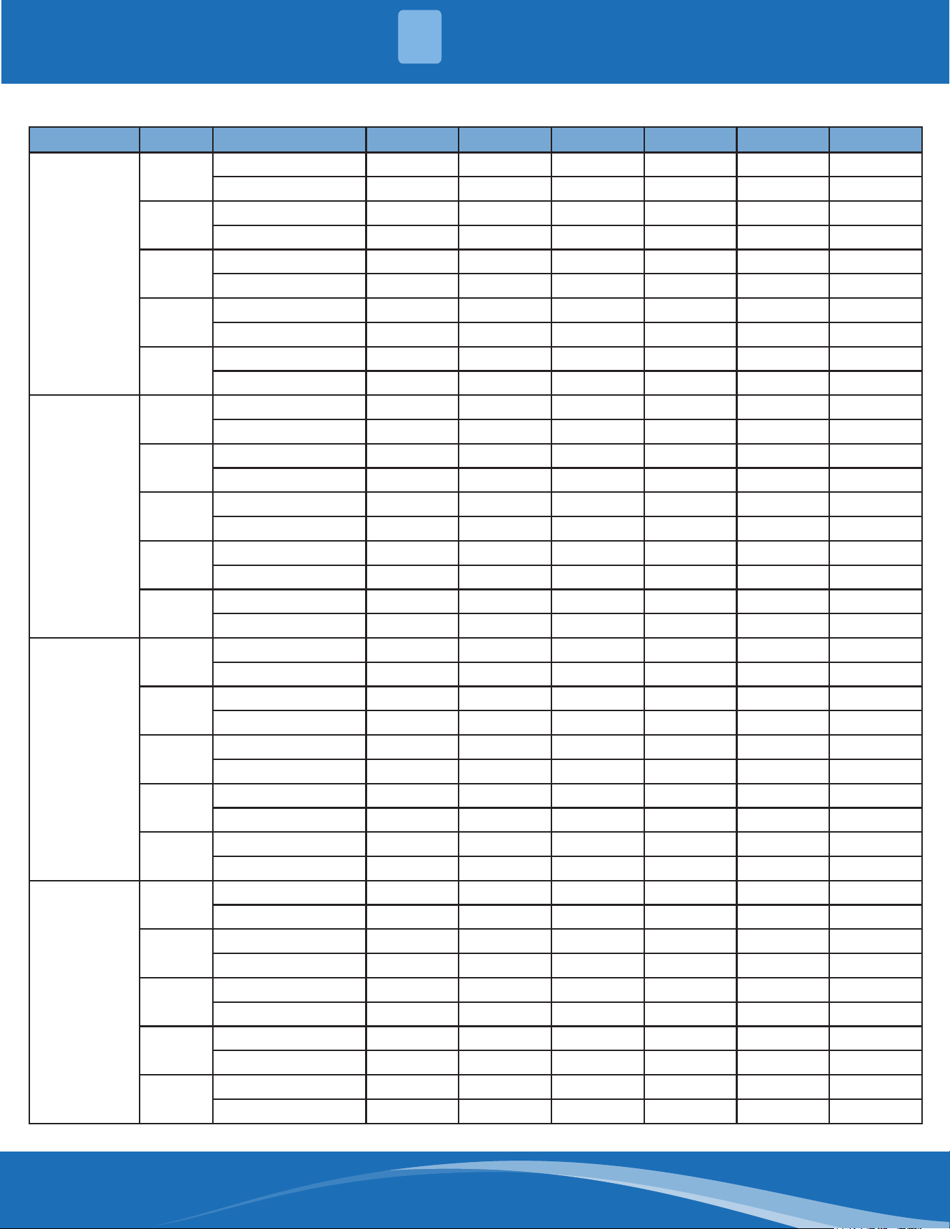
Table 3.6a Air Delivery CFM (Without Filter)
Furnace Size Speed Static Pressure 0 0.2 0.4 0.6 0.8 1
40A3C
H
[SCFM] 1149 1121 1160 1153 1143 1169
Temp Rise °F (°C) 26 27 26 26 26 26
MH
[SCFM] 999 1008 994 1030 990 972
Temp Rise °F (°C) 30 30 30 29 30 31
M
[SCFM] 799 777 797 782 828 809
Temp Rise °F (°C) 37 38 37 38 36 37
ML
[SCFM] 600 611 622 611 577 632
Temp Rise °F (°C) / / / / / /
L
[SCFM] 450 483 460 469 437 454
Temp Rise °F (°C) / / / / / /
60B4C
H
[SCFM] 1301 1294 1313 1325 1301 1288
Temp Rise °F (°C) 34 35 34 34 34 35
MH
[SCFM] 1101 1106 1103 1106 1077 1142
Temp Rise °F (°C) 41 40 41 40 42 39
M
[SCFM] 901 899 889 886 879 918
Temp Rise °F (°C) 50 50 50 50 51 49
ML
[SCFM] 800
816 841 783 824 813
Temp Rise °F (°C) / / / / / /
L
[SCFM] 600 631 635 612 601 610
Temp Rise °F (°C) / / / / / /
80B4C
H
[SCFM] 1301 1294 1313 1325 1301 1288
Temp Rise °F (°C) 46 46 45 45 46 46
MH
[SCFM] 1101 1106 1103 1106 1077 1142
Temp Rise °F (°C) 54 54 54 54 55 52
M
[SCFM] 901 899 889 886 879 918
Temp Rise °F (°C) / / / / / /
ML
[SCFM] 800 816 841 783 824 813
Temp Rise °F (°C) / / / / / /
L
[SCFM] 600 631 635 612 601 610
Temp Rise °F (°C) / / / / / /
80C4C
H
[SCFM] 1301 1297 1271 1251 1343 1240
Temp Rise °F (°C) 46 46 47 48 44 48
MH
[SCFM] 1101 1113 1142 1141 1060 1168
Temp Rise °F (°C) 54 54 52 52 56 51
M
[SCFM] 901 855 905 938 874 924
Temp Rise °F (°C) / / / / / /
ML
[SCFM] 800 785 815 823 798 863
Temp Rise °F (°C) / / / / / /
L
[SCFM] 600 606 593 549 571 549
Temp Rise °F (°C) / / / / / /
mrcool.com19
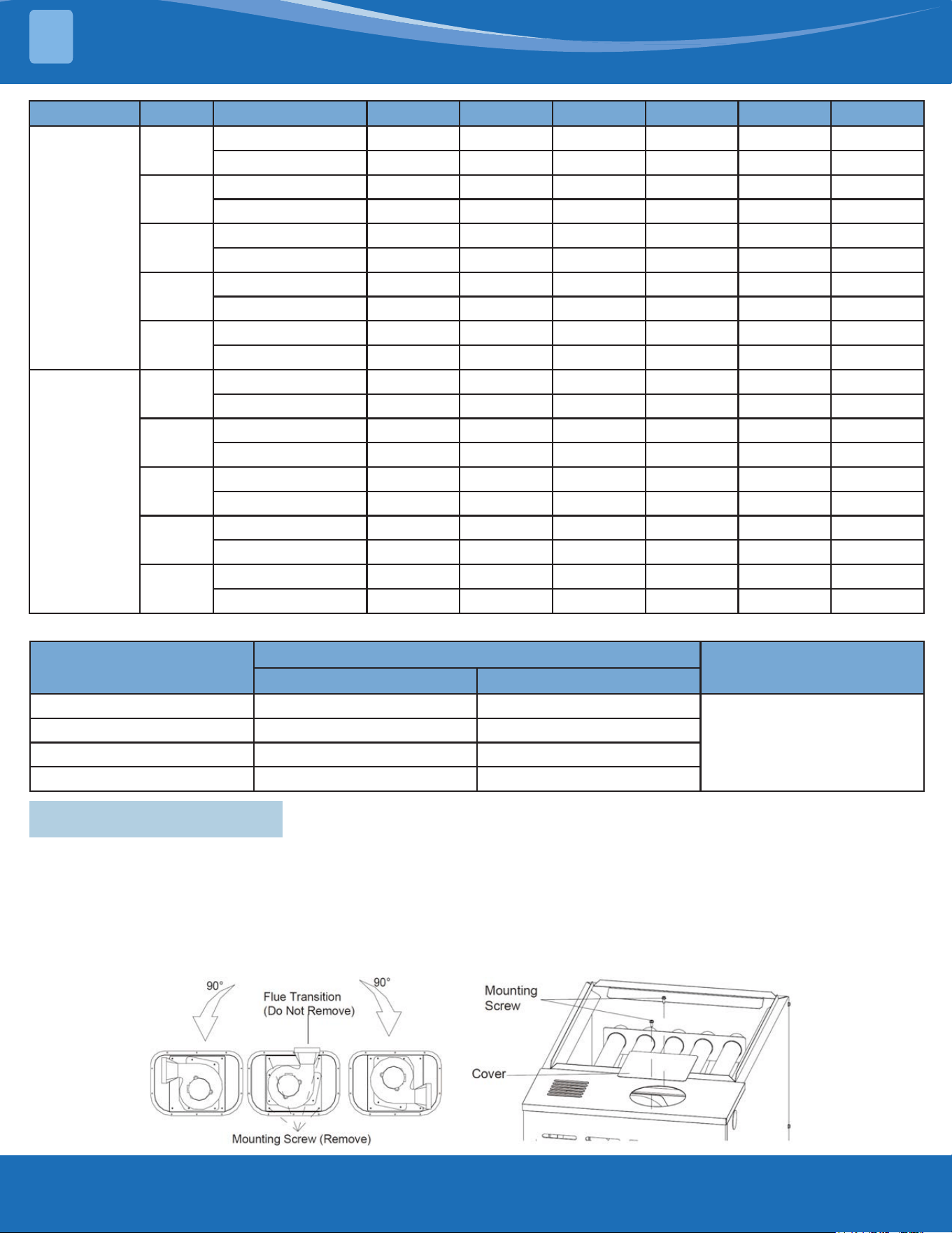
Furnace Size Speed Static Pressure 0 0.2 0.4 0.6 0.8 1
100C5C
H
[SCFM] 1751 1739 1742 1739 1736 1733
Temp Rise °F (°C) 43 43 43 43 43 43
MH
[SCFM] 1501 1516 1492 1500 1499 1505
Temp Rise °F (°C) 50 49 50 50 50 50
M
[SCFM] 1351 1351 1364 1356 1347 1336
Temp Rise °F (°C) 55 55 55 55 55 56
ML
[SCFM] 1151 1154 1152 1132 1154 1142
Temp Rise °F (°C) / / / / / /
L
[SCFM] 1001 995 996 982 981 1013
Temp Rise °F (°C) / / / / / /
120D5C
H
[SCFM] 1951 1910 1896 1929 1981 1917
Temp Rise °F (°C) 38 39 39 39 38 39
MH
[SCFM] 1751 1775 1749 1772 1786 1771
Temp Rise °F (°C) 43 42 43 42 42 42
M
[SCFM] 1501 1570 1575 1569 1543 1544
Temp Rise °F (°C) 50 48 47 48 48 48
ML
[SCFM] 1348
1420 1410 1416 1412 1400
Temp Rise °F (°C) 55 53 53 53 53 53
L
[SCFM] 1148 1210 1196 1174 1179 1175
Temp Rise °F (°C) / / / / / /
Table 3.6b Filter Size Information - in. (mm)
Furnace Casing Width
Filter Size
Filter Type
Side Return Bottom Return
14-1/2 (368) 16X25 (406X635) 14X25 (356X365)
High Velocity (600 FPM)
17-1/2 (445) 16X25 (406X635) 16X25 (406X635)
21 (533) 16X25 (406X635) 20X25 (508X635)
24.5 (622) 16X25 (406X635) 24X25 (610X635)
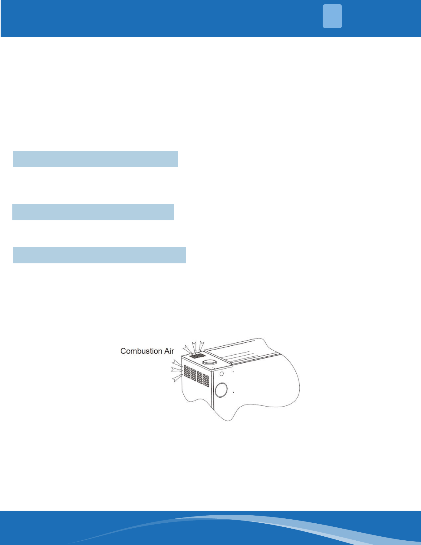
4.1 Vent Connections
The gures below show the furnace as it is shipped from the factory. To convert to a horizontal or downow
position, remove the four screws that secure the inducer assembly and rotate 90° being careful not to damage the
gasket. Reinstall screws. Remove cap from appropriate vent outlet location on the cabinet. Cut the insulation in
cabinet to the same size as the hole provided and reinstall cap in the hole in the top panel.
IMPORTANT: In downow applications, do not block the combustion air inlet. The furnace must be installed on a
coil cabinet or subbase to allow combustion air to enter the burner compartment.
Figure 4.1a
Figure 4.1b
VENTING
4
mrcool.com 20
20
Category 1 - 450°F Max. Vent Temp
The venting system must be installed in accordance with Section 5.3 Air for Combustion and Ventilation, of the
National Fuel Gas Code Z223.1/NFPA 54 (latest edition), or Sections 7.2, 7.3, or 7.4 of CSA B149.1, National Gas and
Propane Codes (latest edition), or applicable provisions of the local building code and these instructions.
The furnace should be connected to a type B vent connector. The furnace should not be connected to a chimney
ue serving a separate appliance designed to burn solid fuel. Single-wall vent pipe is not allowed.
It is recommended that the appliance is installed in a location where the space temperature is 32°F (0°C) or higher.
If the appliance is installed in a location where the temperature is below 32°F (0°C), the combustion byproducts
could condense causing damage to the appliance heat exchanger.
This appliance may be common vented with another gas appliance for residential installations as allowed by the
codes and standards listed in these instructions.
4.2 Venting System Requirements
Category I venting consists of vertically venting one or more appliances in B-vent or B-vent connectors. Type
B-vent system extends in a general vertical direction and does not contain osets exceeding 45°. A vent system
having not more than one 60° oset is permitted.
4.3 Venting into Existing Chimney
This furnace may not be connected to any masonry chimney. However, an existing masonry chimney may be
used as a chase through which the metal vent pipe passes.
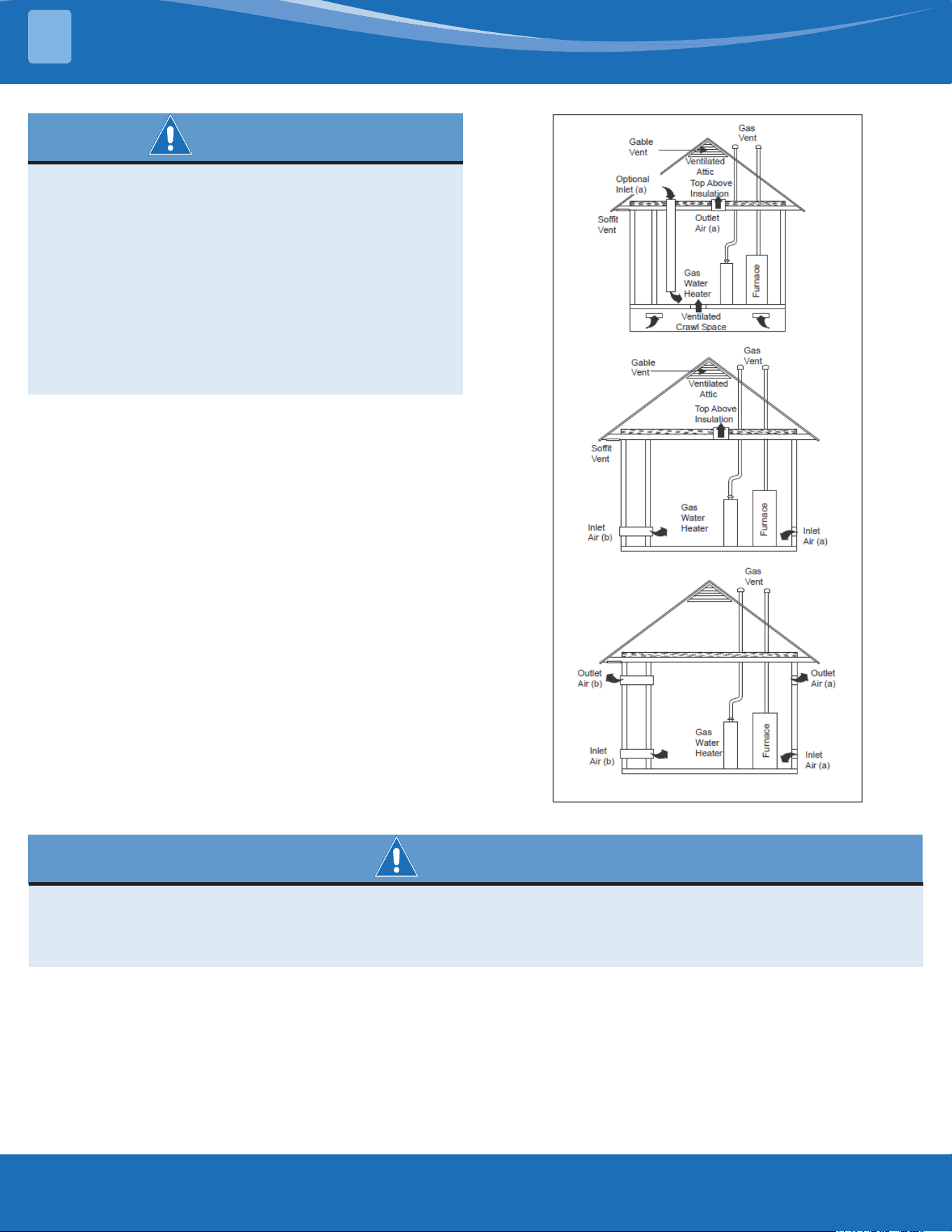
4.4 Air for Combustion & Ventilation
Ambient Combustion Air Supply
This type of installation will draw the air required for combustion from within the space surrounding the appliance
and from areas or rooms adjacent to the space surrounding the furnace. This may be from within the space in a
non-conned location or it may be brought into the furnace area from outdoors through permanent openings or
ducts.
A single, properly sized pipe from the furnace vent connector to the outdoors must be provided. For upow
models, combustion air is brought into the furnace through the unit's top panel opening.
Figure 4.4a
VENTING
4
mrcool.com21
VENTING
4
WARNING
This type of installation requires that the supply
air to the appliance(s) be of an amount sucient
enough to support all of the appliance(s) in the
area. Operation of a mechanical exhaust, such as
an exhaust fan, kitchen ventilation system, clothes
dryer or replace may create conditions requiring
special attention to avoid unsatisfactory operation of
gas appliances. A venting problem or a lack of supply
air will result in hazardous conditions, which can
cause the appliance to soot and generate dangerous
levels of carbon monoxide, which can lead to serious
injury, property damage and/or death.
An unconned space is not less than 50 cu.ft (1.42m3)
per 1,000Btu/hr (0.2928 kW) input rating for all of the
appliances installed in that area.
Rooms communicating directly with the space
containing the appliances through openings not
furnished with doors, are considered a part of the
unconned space.
In unconned spaces (see denition below) in
buildings, inltration may be adequate to provide air
for combustion ventilation and dilution of ue gases.
However, in buildings of tight construction (for example,
weather stripping, heavily insulated, caulked, vapor
barrier, etc.), additional air may need to be provided
using the methods described in the "conned space”
section.
A conned space is an area with less than 50 cu.ft
(1.42m3) per 1,000 Btu/hr (0.2928 kW) input rating for
all of the appliances installed in that area. The following
must be considered to obtain proper air for combustion
and ventilation in conned spaces.
Figure 4.4b
WARNING
When a Category I furnace is removed or replaced, the original venting system may no longer be correctly
sized to properly vent the attached appliances.
An improperly sized vent system can cause carbon monoxide to spill into the living space causing personal
injury, and or death.
Equipment Located in Conned Spaces:
a) All air from inside the building:
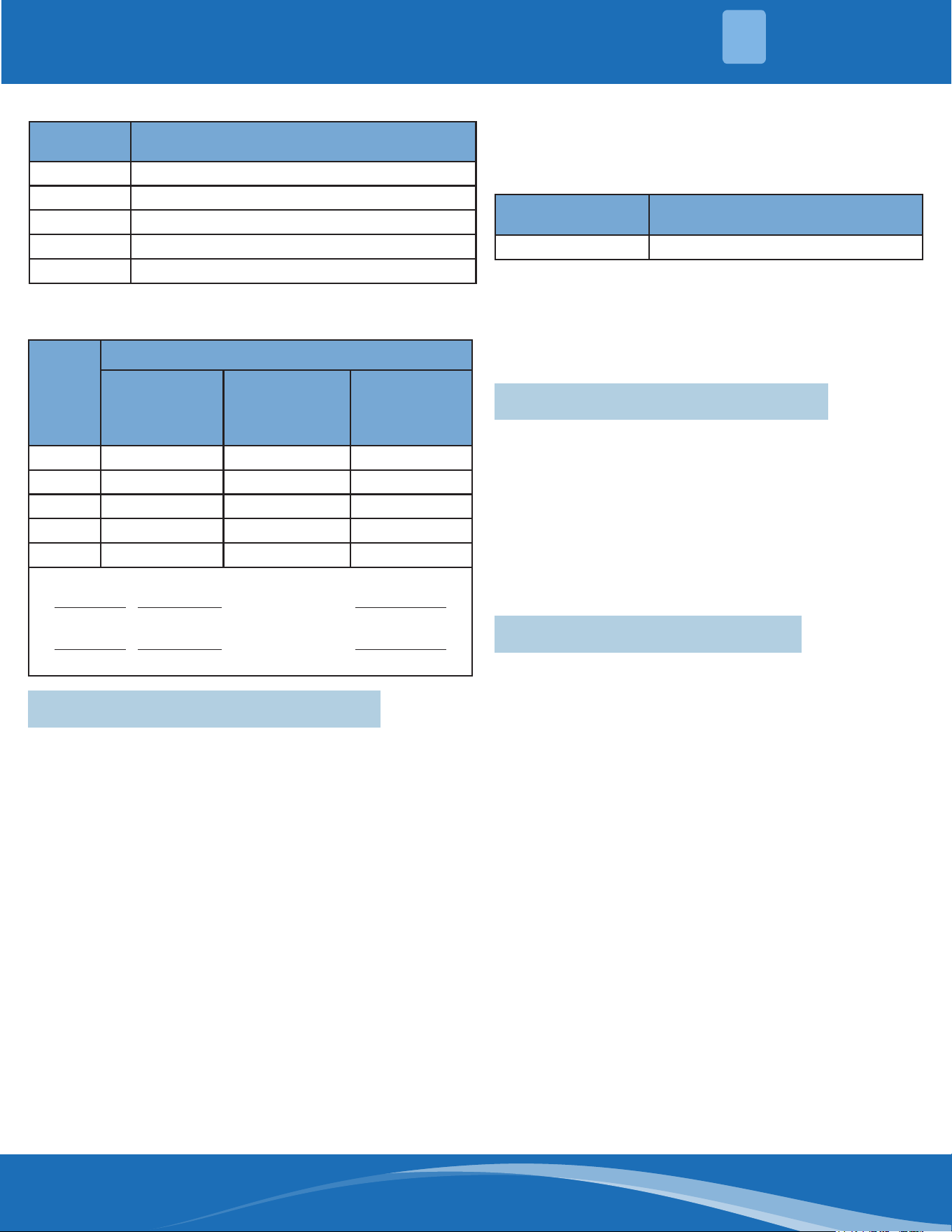
The conned space shall be provided with two permanent openings communicating directly with an additional
room(s) of sucient volume so that the combined volume of all spaces meets the criteria. The total input of all
gas utilization equipment installed in the combined space shall be considered in making this determination. Each
opening shall have a minimum free area of 1 square inch per 1,000BTU per hour of the total input rating of all gas
utilization equipment in the conned space. One opening shall be within 12 inches of the top and one within 12
inches of the bottom of the enclosure (See Table 4.4a).
mrcool.com 22
22
VENTING
4
BTUH Input
Rating
Minimum Free Area Required per Opening
in
2
(cm
2
)
40,000 40 in
2
(322 cm
2
)
60,000 60 in
2
(450 cm
2
)
80,000 80 in
2
(516 cm
2
)
100,000 100 in
2
(645 cm
2
)
120,000 120 in
2
(742 cm
2
)
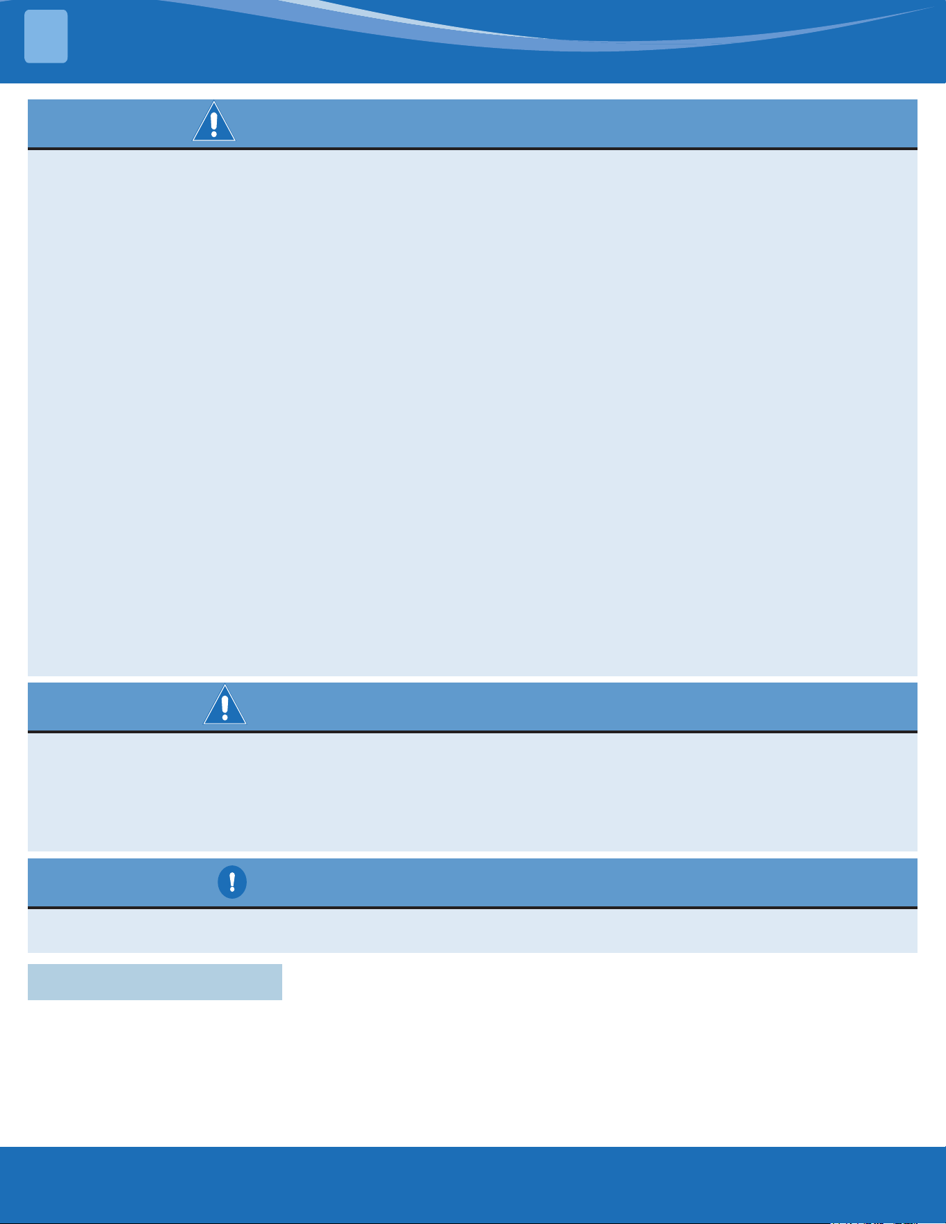
b) All air from outdoors:
BTUH
Input
Rating
Minimum Free Area Required per Opening
Horizontal
Duct (2,000
BTUH)
Vertical Duct
or Opening to
Outside (4,000
BTUH)
Round Duct
(4,000 BTUH)
40,000 20 in
2
(129 cm
2
) 10 in
2
(65 cm
2
) 4" (10 cm)
60,000 30 in
2
(226 cm
2
) 15 in
2
(96.8 cm
2
) 5" (13 cm)
80,000 40 in
2
(258 cm
2
) 20 in
2
(129 cm
2
) 5" (13 cm)
100,000 50 in
2
(323 cm
2
) 25 in
2
(161 cm
2
) 6" (15 cm)
120,000 60 in
2
(387 cm
2
) 30 in
2
(194 cm
2
) 7" (18 cm)
EXAMPLE: Determining Free Area
Appliance 1 Appliance 2 Total Input
100,000 + 30,000 = (130,000 / 4,000) = 32.5 in
2
Vertical
Appliance 1 Appliance 2 Total Input
100,000 + 30,000 = (130,000 / 2,000) = 65 in
2
Horizontal
Table 4.4a
Table 4.4b
4.5 Air Supply Openings & Ducts
1. Two permanent openings, one within 12 in
(305 mm) of the top and one within 12 in (305
mm) of bottom of the conned space, should
communicate directly or by means of ducts with
the outdoors, crawl spaces or attic spaces.
2. One permanent opening, commencing within 12
in (305 mm) of the top of the enclosure shall be
permitted where the equipment has clearances
of at least 1 in (25.4 mm) from the sides and
back and 6 in (152.4 mm) from the front of the
appliance. The opening should communicate
directly with the outdoors and shall have a
minimum free area of:
a. 1 square inch per 3000 Btu per hour (734
mm2/kW) of the total input rating of all
equipment located in the enclosure.
b. Not less than the sum of all vent connectors
in the conned space.
3. The duct should be least the same cross-sectional
area as the free area of the air supply inlet
opening to which it connects.
Wood or Metal
Louvers or Grilles
Wood 20-25%
Metal 60-70%
Screens + 1/4" (0.635cm) mesh or larger 100%
5. An opening may be used in lieu of a duct to
provide the outside air supply to an appliance
unless otherwise permitted by the authority having
jurisdiction. The opening should be located within
12" (30.5 cm) horizontally from the burner level of
the appliance.
4.6 Ventilated Combustion Air
The ventilated attic space or a crawl space from
which the combustion air is taken must comply with
the requirements specied in this manual and the Air
for Combustion and Ventilation of the National Fuel
Gas Code, ANSI Z223.1 (latest edition). This type of
installation requires two properly sized pipes. One
brings combustion air from a properly ventilated attic
space or crawl space and a second pipe that extends
from the furnace vent connection (top right of unit) to
the exterior of the building.
For Category I furnaces, vent installations shall be in
accordance with Parts 7 and 11 of the National Fuel
Gas Code, ANSI Z223.1/NFPA 54 and or Section 7
and Appendix B of the CAS B 149.1, Natural Gas and
Propane Installation Codes, the local building codes,
and furnace and vent manufacturer’s instructions.
Multi-story or common venting systems are permitted
and must be installed in accordance with the National
Fuel Gas Code, ANSI Z223.1/NFPA 54 and / or the CSA
B 149.1, Natural Gas and Propane Installation Codes,
and the manufacturer’s instructions.
Vent connectors serving Category I furnaces shall not
be connected into any portion of mechanical draft
systems operating under positive pressure.
Horizontal portions of the venting system shall be
supported to prevent sagging using hangers or
perforated straps and must slope upwards not less
than 1/4" per foot (0.635 cm/m) from the furnace to
the vent terminal.
It is recommended that you follow the venting safety
procedure. This procedure is designed to detect an
inadequate ventilation system that can cause the
appliances in the area to operate improperly causing
unsafe levels of carbon monoxide or create unsafe
conditions.
4. The blocking eects of louvers, grilles and screens
must be given consideration in calculating free
area. If the free area of a specic louver or grille is
not known, refer to “Estimated Free Area” table to
estimated free area.
4.7 Safety Check Procedure
mrcool.com23
CARBON MONOXIDE POISONING HAZARD
Failure to follow the steps outlined below for each appliance connected to the venting system being placed
into operation could result in carbon monoxide poisoning or death. The following steps shall be followed
for each appliance connected to the venting system being placed into operation, while all other appliances
connected to the venting system are not in operation:
1. Inspect the venting system for proper size and horizontal pitch. Determine that there is no blockage,
restriction, leakage, corrosion or other deciencies, which could cause an unsafe conditions.
2. Close all building doors and windows and all doors.
3. Turn on clothes dryers and any exhaust fans, such as range hoods and bathroom exhausts, so they shall
operate at maximum speed. Open the replace damper. Do not operate a summer exhaust fan.
4. Follow the lighting instructions. Place the appliance being inspected into operation. Adjust
thermostat so the appliance shall operate continuously.
5. Test each appliance (such as a water heater) equipped with a draft hood for spillage
(down-draft or no draft) at the draft hood relief opening after 5 minutes of main burner operation. Appliances
that do not have draft hoods need to be checked at the vent pipe as close to the appliance as possible. Use
a combustion analyzer to check the CO2 and CO levels of each appliance. Use a draft gauge to check for a
downdraft or inadequate draft condition.
6. After it has been determined that each appliance properly vents when tested as outlined above, return
doors, windows, exhaust fans, replace dampers and any other gas burning appliance to their normal
condition.
7. If improper venting is observed during any of the above tests, a problem exists with either
the venting system or the appliance does not have enough combustion air (supply air from outside) to
complete combustion. This condition must be corrected before the appliance can function safely.
NOTE: An unsafe condition exists when the CO reading exceeds 40 ppm and the draft reading is not in excess
of -0.1 in. W.W.(-25 kPa) with all of the appliance(s) operating at the same time.
8. Any corrections to the venting system and/or to the supply (outside) air system must be in accordance with
the National Fuel Gas Code Z223.1 or CAN/CGA B149.1 Natural Gas and Propane Installation Code (latest
editions). If the vent system must be resized, follow the appropriate tables in Appendix G of the above codes
or for this appliance.
WARNING-FIRE & EXPLOSION HAZARDS
• Never purge a gas line into a combustion chamber. Never test for gas leaks with an open ame. Use a
commercially available soap solution made specically for the detection of leaks to check all connections.
• Use proper length of pipe to avoid stress on the gas control manifold and a gas leak.
• If local codes allow the use of a exible gas appliance connector, always use a new listed connector. Do not
use a connector which has previously served another gas appliance. Black iron pipe shall be installed at the
furnace gas control valve and extend a minimum of 2 in. (51 mm) outside the unit.
CAUTION-FURNACE OVERHEAT HAZARD
Connect gas pipe to gas valve using a backup wrench to avoid damaging gas controls and causing burner
misalignment.
5.1 General Overview
The furnace rating plate includes the approved furnace gas input rating and gas types. The furnace must be
equipped to operate on the type of gas applied. This includes any conversion kits required for alternate fuels and/
or high altitude.
Inlet gas supply pressures must be maintained within the ranges specied. The supply pressure must be constant
and available with all other household gas-red appliances operating. The minimum gas supply pressure must be
maintained to prevent unreliable ignition. The maximum must not be exceeded to prevent unit over-ring.
GAS SUPPLY & PIPING
5
mrcool.com 24
24
GAS SUPPLY & PIPING
5
Inlet Gas Supply Pressure
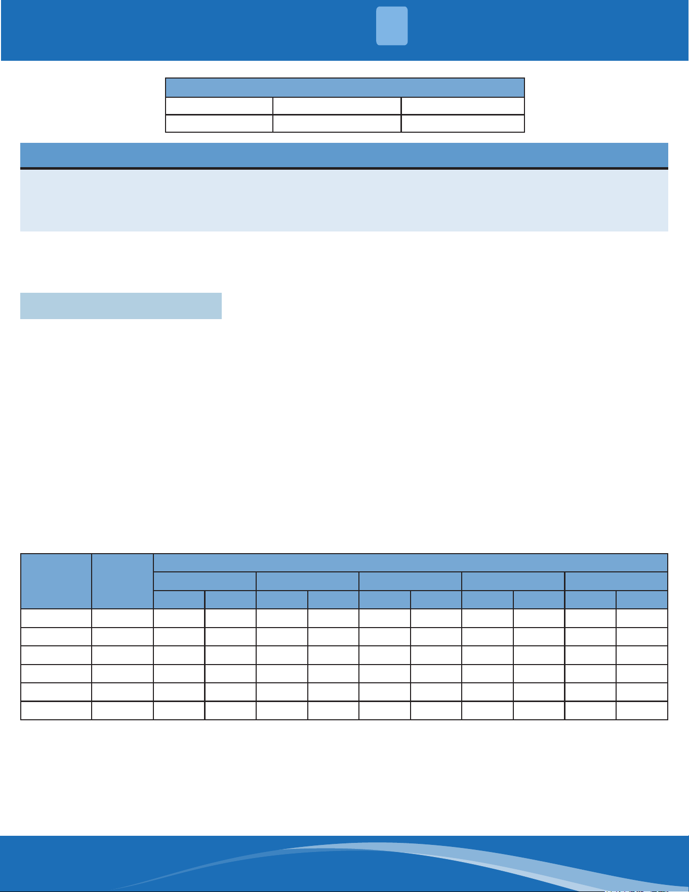
Natural Gas Minimum: 5.0" W.C. Maximum: 10.5" W.C.
Propane Gas Minimum: 11.0" W.C. Maximum: 13.0" W.C.
NOTE
Adjusting the minimum supply pressure below the limits in the above table could lead to unreliable ignition.
Gas input to the burners must not exceed the rated input shown on the rating plate. Over-ring of the furnace
can result in premature heat exchanger failure. Gas pressures in excess of 13 inches water column can also
cause permanent damage to the gas valve.
At all altitudes and with either fuel, the air temperature rise must be within the range listed on the furnace
nameplate. If the furnace needs to be converted to LP, refer to the instructions included in the factory authorized
LP conversion kit.
5.2 High Altitude Derate
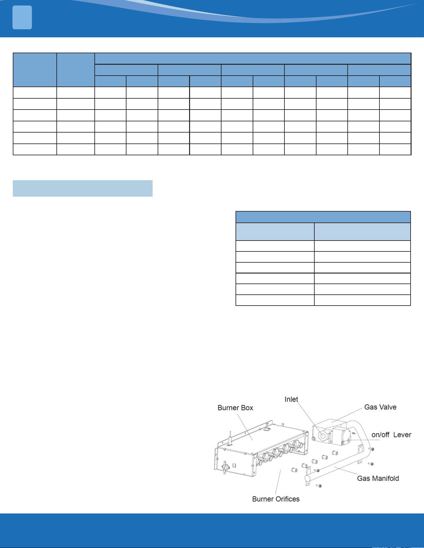
Alternate standard derate for altitude from National Fuel Gas Code ANSI Z223.1 of 4% per 1000' may be taken.
Refer to the most recent version of ASNI Z223.1 for correct gas orice. The orices must be selected using the table
below. The furnace derate is 4% for each 1,000 feet above sea level. This table is based upon a heating value of
approximately 1,000 Btu/ft3.
In Canada, the input rating must be derated by 10% for altitudes of 2,000 ft. (610m) to 4,500 feet (1370m) above sea
level by an authorized Gas Conversion Station or Dealer.
When an appliance is installed at elevations above 4500ft (1350m), the certied high-altitude input rating shall be
reduced at the rate of 4% for each additional 1000ft (300m).
In some areas the gas supplier may articially derate the gas in an eort to compensate for the eects of altitude.
If the gas is articially derated, the appropriate orice size must be determined based upon the BTU/ft3 content of
the derated gas and the altitude. Refer to the latest version of NFPA54/ANSI Z223.1 for US and the latest version of
CSA B149.1 for Canada., and information provided by the gas supplier to determine the proper orice size.
Table 5.2a
Input Rate
KBTU/H
Number
of
Burners
Elevation (ft)
0-2000 2000-4000 4000-6000 6000-8000 8000-10000
Nat LP Nat LP Nat LP Nat LP Nat LP
40A3C 3 50 59 51 61 52 62 53 64 54 65
60B4C 3 45 55 47 56 48 56 49 57 51 57
80B4C 5 49 56 50 57 51 58 52 59 53 61
80C4C 5 49 56 50 57 51 58 52 59 53 61
100C5C 6 49 56 50 57 51 58 52 59 53 61
120D5C 7 49 56 50 57 51 58 52 59 53 61
*LP Orice based on 10 in. W.C. manifold pressure
The input to the furnace must be checked AFTER re-oricing.
US Installation
mrcool.com25
Input Rate
KBTU/H
Number
of
Burners
Elevation (ft)
0-2000 2000-4000 4000-6000 6000-8000 8000-10000
Nat LP Nat LP Nat LP Nat LP Nat LP
40A3C 3 50 59 51 61 52 62 53 64 54 65
60B4C 3 45 55 47 56 48 56 49 57 51 57
80B4C 5 49 56 50 57 51 58 52 59 53 61
80C4C 5 49 56 50 57 51 58 52 59 53 61
100C5C 6 49 56 50 57 51 58 52 59 53 61
120D5C 7 49 56 50 57 51 58 52 59 53 61
Canada Installation
*LP Orice based on 10 in. W.C. manifold pressure
The input to the furnace must be checked AFTER re-oricing.
The gas supply shall be shut o prior to disconnecting the electrical power before proceeding with conversion.
1. Make sure all utilities (gas and electricity) are turned o
2. Remove the furnace front panel
3. Disconnect the gas line from the gas valve
4. Disconnect the wires at gas control.
To Replace Orices with LP Orices from Gas Manifold
1. Disconnect all control wires
2. Remove 4 screws holding gas manifold to
supporting burner assembly bracket
3. Slide the manifold (with valve and orices) out of
burners. Be careful not to damage the assembly.
4. Replace the natural gas orices with the LP orices
or appropriate high altitude orices
5. Re-assemble the gas manifold and re-connect all
wires.
5.3 Propane Gas Conversion
Possible property damage, personal injury or death may occur
if the correct conversion kits are not installed. The appropriate
kits must be applied to ensure safe and proper furnace
operation. All conversions must be performed by a qualied
installer or service agency.
This unit is congured for natural gas. The appropriate
manufacturer's propane gas conversion kit must be applied for
propane gas installations. For high altitude Installations refer
to the "High Altitude Derate" section on page 24 for details.
Contact your distributor for a tabular listing of appropriate
manufacturer's kits for propane gas and/or high altitude
installations. The indicated kits must be used to insure safe and
proper furnace operation. All conversions must be performed
by a qualied installer, or service agency.
GAS SUPPLY & PIPING
5
Table 5.2b
Figure 5.3
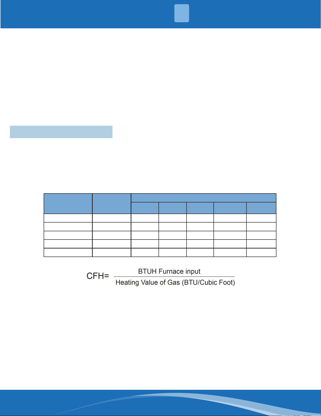
VersaPro Furnace LP Kit Compatibility Chart
Furnace Model
Corresponding MRCOOL®
LP Kit Model
MGA80EE080B4C MLP8SSB
MGA80EE100C5C MLP8SSB
MGA80EE120D5C MLP8SSB
MGA80EE080C4C MLP8SSB
MGA80EE060B4C MLP8SSB
MGA80EE040A3C MLP8SSB
mrcool.com 26
26
To Convert from Natural to LP Gas on Gas Valve
1. Remove regulator (gas valve) cover screw.
2. Remove regulator adjustment screw (beneath the cover screw).
3. Remove natural gas spring from regulator sleeve.
4. Insert the LP spring included in the conversion kit into sleeve.
5. Replace the adjustment screw and adjust the outlet pressure to manufacturer’s specied outlet pressure.
6. Replace the regulator cover screw.
7. Attach the WARNING label (provided in the kit) to the gas valve, attach small round LP label to the top of
regulator cover screw.
8. Fill required blanks in provided conversion label and attach it to appropriate location on furnace case.
5.4 Gas Piping Connections
To avoid possible unsatisfactory operation or equipment damage due to under-ring of equipment, use the proper
size of natural propane gas piping needed when running pipe from the meter/tank to the furnace.
When sizing a trunk line, be sure to include all appliances which will operate simultaneously.
The gas piping supplying the furnace must be properly sized based on the gas ow required, specic gravity of the
gas, and length of the run. The gas line installation must comply with local codes, or in their absence, refer to the
latest version of NFPA54/ANSI Z223.1 for US and the latest version of CSA B149.1 for Canada.
GAS SUPPLY & PIPING
5
Nominal Iron
Pipe Size
in. (mm)
Internal
DIA. in.
(mm)
Length of Pipe - ft(m)
10 (3.0) 20 (6.0) 30 (9.1) 40 (12.1) 50 (15.2)
1/2 (12.7) 0.622 (15.8) 175 120 97 82 73
3/4 (19.0) 0.824 (20.9) 360 250 200 170 151
1 (25.4) 1.049 (26.6) 680 465 375 320 285
1-1/4 (31.8) 1.380 (35.0) 1400 950 770 660 580
1-1/2 (38.1) 1.610 (40.9) 2100 1460 1180 990 900
(Pressure 0.5 psig or less and pressure drop of 0.3" W.C.; Based on 0.60 Specic Gravity Gas)
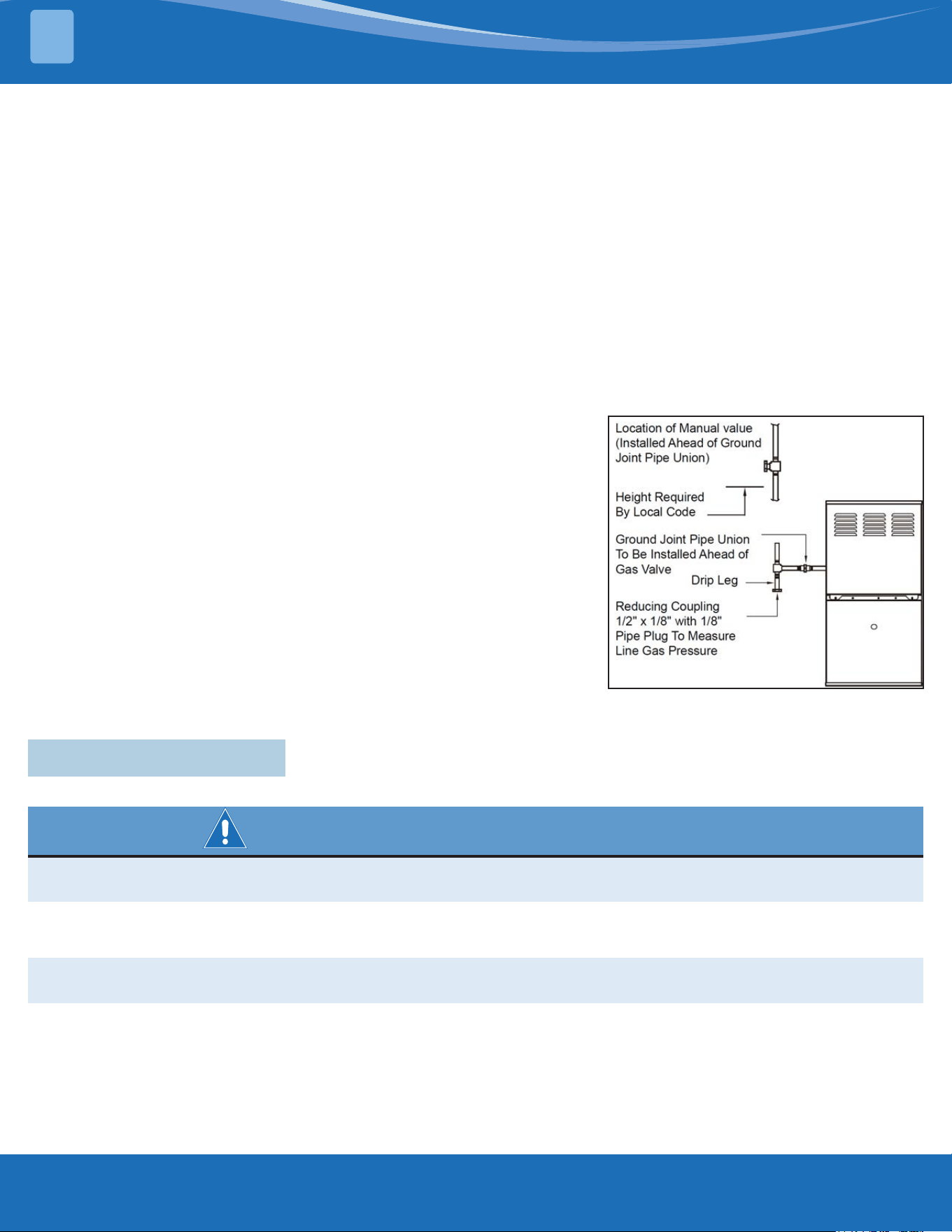
To connect the furnace to the building's gas piping, the installer must supply a ground joint union, drip leg,
manual shuto valve, and line and ttings to connect to the gas valve. In some cases, the installer may also need
to supply a transition piece from 1/2" pipe to a larger pipe size.
The following stipulations apply when connecting gas piping:
• Use black iron or steel pipe and ttings for the building piping.
• Use pipe joint compound on male threads only. Pipe joint compound must be resistant to the action of the
fuel used.
• Use ground joint unions.
• Install a drip leg to trap dirt and moisture before it can enter the gas valve. The drip leg must be a minimum
of three inches long.
• Install a 1/8" NPT pipe plug tting, accessible for test gage connection, immediately upstream of the gas
supply connection to the furnace.
Table 5.4
mrcool.com27
• 90° elbows (2)
• Close nipple
• Straight pipe to reach the exterior of the furnace
• A ground joint union, drip leg, and manual shuto valve must also be
supplied by the installer. In some cases, the installer may also need
to supply a transition piece from 1/2" to another pipe size.
When the gas piping enters through the left side of the furnace, the
installer must supply the following ttings (starting from the gas valve):
• Straight pipe to reach the exterior of the furnace.
• A ground joint union, drip leg, and manual shuto valve must also be
supplied by the installer. In some cases, the installer may also need
to supply a transition piece from 1/2 inch to another pipe size.
5.5 Gas Piping Checks
Before placing the unit in operation, leak test the unit and gas connections.
WARNING-FIRE & EXPLOSION HAZARDS
Never test for gas leaks with an open ame. Use a commercially available soap solution made specically for
the detection of leaks to check all connections.
Check for leaks using an approved chloride-free soap and water solution, an electronic combustible gas detector,
or other approved testing methods.
NOTE: Never exceed specied pressures for testing. Higher pressure may damage the gas valve and cause
subsequent over-ring, resulting in heat exchanger failure.
Disconnect this unit and shuto valve from the gas supply piping system before pressure testing the supply piping
system with pressures in excess of 1/2 psig (3.48 kPa).
This unit must be isolated from the gas supply system by closing its manual shuto valve before pressure testing
of gas supply piping system with test pressures equal to or less than 1/2 psig (3.48 kPa).
GAS SUPPLY & PIPING
5
Figure 5.4
• Use two pipe wrenches when making connection to the gas valve to keep it from turning. The orientation of
the gas valve on the manifold must be maintained as shipped from the factory.
• Install a manual shuto valve between the gas meter and unit within six feet of the unit. If a union is
installed, the union must be downstream of the manual shuto valve, between the shuto valve and the
furnace.
• Tighten all joints securely.
Connect the furnace to the building piping using rigid metallic pipe and ttings or semi-rigid metallic tubing and
metallic ttings. Aluminum alloy tubing must not be used in exterior locations.
Use listed gas appliance connectors in accordance with their instructions. Connectors must be fully in the same
room as the furnace.
Protect connectors and semi-rigid tubing against physical and thermal damage when installed. Ensure
aluminum-alloy tubing and connectors are coated to protect against external corrosion when in contact with
masonry, plaster, or insulation, or subjected to becoming wet by liquids such as water (except rain water),
detergents, or sewage.
When the gas piping enters through the right side of the furnace, the installer must supply the following ttings
(starting from the gas valve):
mrcool.com 28
28
ELECTRICAL CONNECTIONS
6
WARNING-ELECTRICAL SHOCK & FIRE HAZARDS
• Blower access panel door switch opens 115V power to control. No component operation can occur. Do not
bypass or close switch with panel removed.
• The cabinet MUST have an uninterrupted or unbroken ground according to NEC ANSI/NFPA 70-2008 and
Canadian Electrical Code CSA C22.1 or local codes to minimize personal injury if an electrical fault should
occur.
• This may consist of electrical wire, conduit approved for electrical ground or a listed, grounded power cord
(where permitted by local code) when installed in accordance with existing electrical codes. Refer to the
power cord manufacturer's ratings for proper wire gauge. Do not use gas piping as an electrical ground.
• Do not connect aluminum wire disconnect switch and furnace. Use only copper wire.
CAUTION-FURNACE NON-OPERATIONAL
• Failure to follow this caution may result in intermittent furnace operation.
• Furnace control must be grounded for proper operation or else control will lock out. Control must remain
grounded through green/yellow wire routed to gas valve and manifold bracket screw.
6.1 115V Wiring
Verify that the voltage, frequency, and phase correspond to that specied on unit rating plate. Also, check to be
sure that service provided by utility is sucient to handle load imposed by this equipment. Refer to rating plate for
equipment electrical specications.
U.S. installations: Make all electrical connections in accordance with National Electrical Code (NEC) ANSI/NFPA 70-
2008 and any local codes or ordinances that might apply. Canadian installations: Make all electrical connections in
accordance with Canadian Electrical Code CSA C22.1 or authorities having jurisdiction.
Use a separate, fused branch electrical circuit with a properly sized fuse or circuit breaker for this furnace. See table
for wire size and fuse specications. A readily accessible means of electrical disconnect must be located within sight
of the furnace.
Check all factory and eld electrical connections for tightness. Field-supplied wiring should conrm with the
limitations of a 63°F (32°C) rise.
NOTE
Proper polarity must be maintained for 115V wiring. If polarity is incorrect, control LED status indicator light
will ash rapidly and furnace will NOT operate.
Junction Box Relocation
NOTE
If factory location of J-Box is acceptable, go to next section.
On 14" wide casing models, the J-Box shall not be relocated to other side of furnace casing when the vent pipe
is routed within the casing.
1. Remove and save two screws holding J-Box.
NOTE
The J-Box cover does not need to be removed from the J-Box in order to move the J-Box. Do NOT remove the
green ground screw inside J-Box. The ground screw is not threaded into the casing ange and can be lifted out
of the clearance hole in casing while swinging the front edge of the J-Box outboard of the casing.
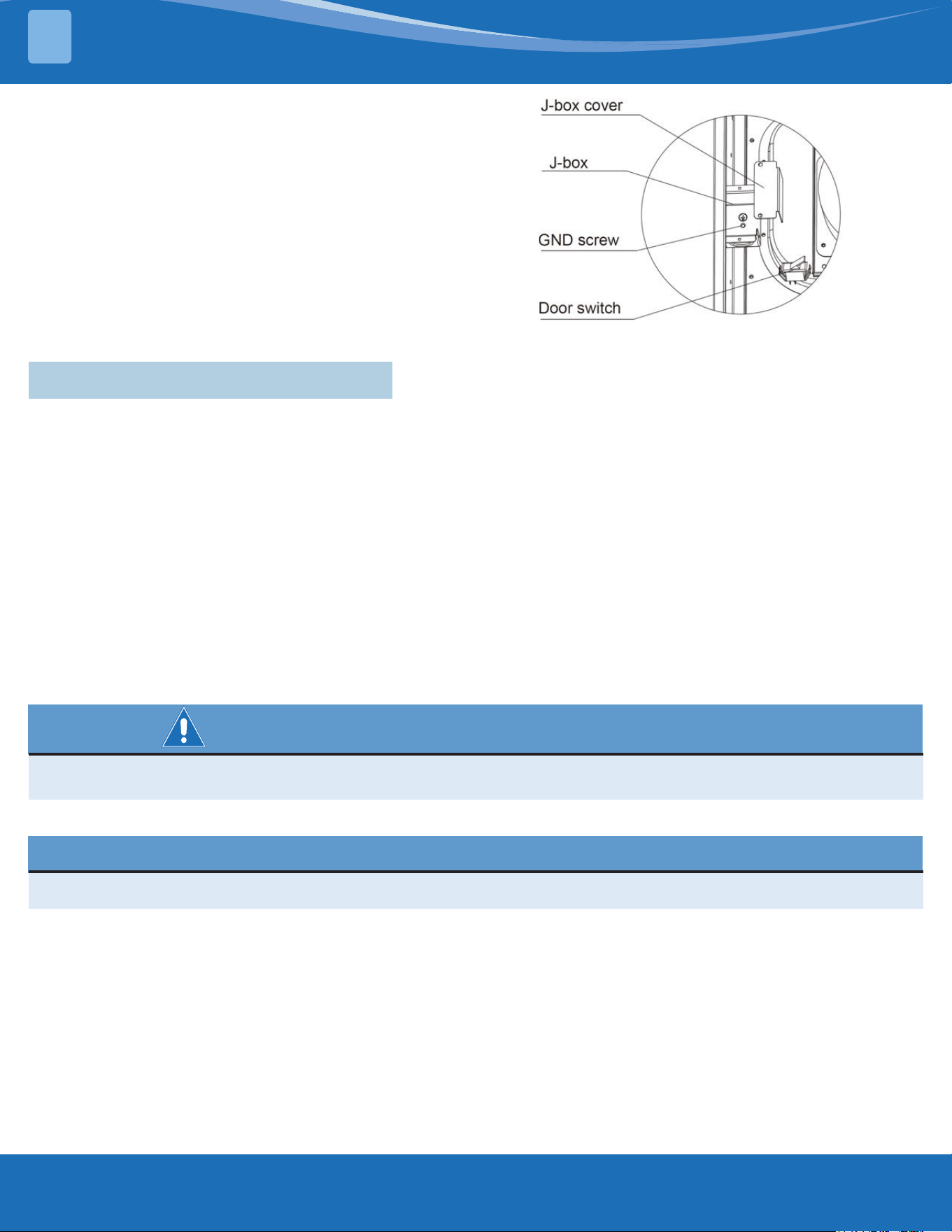
mrcool.com29
ELECTRICAL CONNECTIONS
6
2. Cut wire tie on loop in furnace wires attached to J-box.
3. Move J-Box to desired location.
4. Fasten J-Box to casing with two screws removed in
Step 1.
5. Route J-Box wires within furnace away from sharp
edges, rotating parts and hot surfaces.
6.2 Electrical Connection to J-Box
1. Remove cover from furnace J-Box.
2. Attach electrical box to furnace J-Box bracket with at least two eld-supplied screws through holes in electrical
box into holes in bracket. Use blunt-nose screws that will not pierce wire insulation.
3. Route furnace power wires through holes in electrical box and J-Box bracket, and make eld-wire connections
in electrical box. Use best practices (NEC in U.S. and CSA C22.1 in Canada) for wire bushings, strain relief, etc.
4. Route and secure eld ground wire to green ground screw on J-Box bracket, or the furnace will fail to operate.
5. Connect line voltage leads.
6. Reinstall cover to J-Box. Do not pinch wires between cover and bracket.
Field-Supplied Electrical Box on Furnace J-Box Bracket
Figure 6.1
1. Select and remove a hole knockout in the casing where the electrical box is to be installed.
Electrical Box on Furnace Casing Side
WARNING-ELECTRICAL SHOCK & FIRE HAZARD
If eld-supplied manual disconnect switch is to be mounted on furnace casing side, select a location where a
drill or fastener cannot damage electrical or gas components.
NOTE
Check that the duct on the side of the furnace will not interfere with installed electrical box.
2. Remove the desired electrical box hole knockout and position the hole in the electrical box over the hole in the
furnace casing.
3. Fasten the electrical box to casing by driving two eld-supplied screws from inside electrical box into casing
steel.
4. Remove and save two screws holding J-Box. (See Fig. 6.1.)
5. Pull furnace power wires out of l/2-in. (13 mm) diameter hole in J-Box. Do not loosen wires from strain-relief
wire-tie on outside of J-Box.
6. Route furnace power wires through holes in casing and electrical box and into electrical box.
7. Pull eld power wires into electrical box.
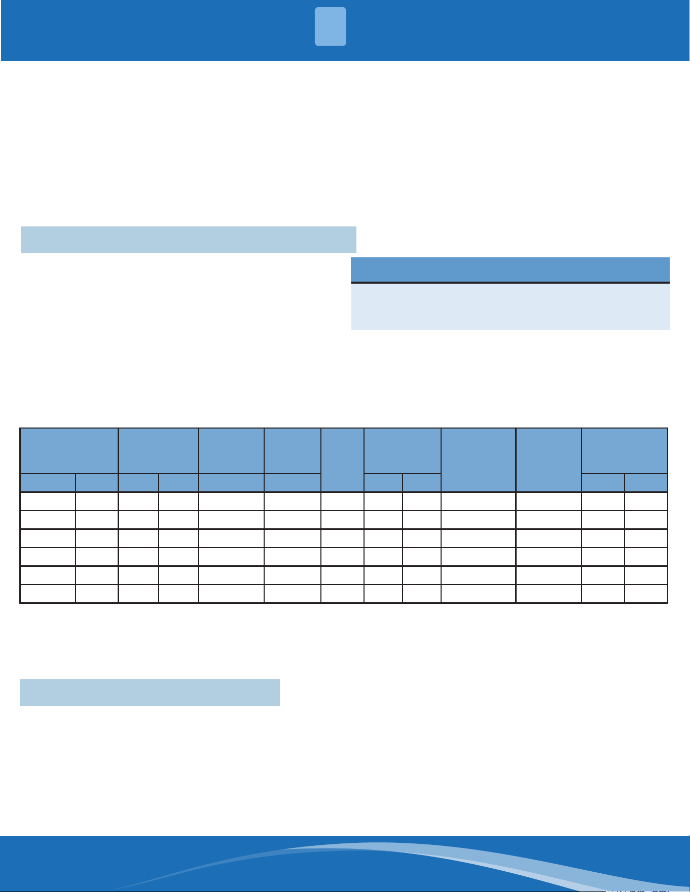
mrcool.com 30
30
ELECTRICAL CONNECTIONS
6
8. Remove cover from furnace J-Box.
9. Route eld ground wire through holes in electrical box and casing, and into furnace J-Box.
10. Reattach furnace J-Box to furnace casing with screws removed in Step 4.
11. Secure eld ground wire to J-Box green ground screw.
12. Complete electrical box wiring and installation.
13. Connect line voltage leads as shown in Fig. 6.7c. Use best practices (NEC in U.S. and CSA C22.1 in Canada) for
wire bushings, strain relief, etc.
14. Reinstall cover to J-Box. Do not pinch wires between cover and bracket.
6.3 Power Cord Installation to J-Box
1. Remove cover from J-Box.
2. Route listed power cord through 7/8-in. (22 mm)
diameter hole in J-Box.
3. Secure power cord to J-Box bracket with a strain relief
bushing or a connector approved for the type of cord
used.
NOTE
Power cords must be able to handle the electrical
requirements listed in the table. Refer to the power
cord manufacturer's literature.
Input Output
Nominal
Airow
MAX.
Unit
AFUE
Air Temp
Rise
Max Over-
Current
Protection
Amps
Min.
Wire Size
(awg) @
75ft
Max. Outlet
Air Temp
MBH KW MBH KW CFM Amps °F °C °F °C
40A3C 11.7 32 9.4 850 8.0 80 35 19.4 15 14 150 65.6
60B4C 17.6 48 14.1 1100 8.0 80 40 22.2 15 14 155 68.3
80B4C 23.4 64 18.8 1300 8.0 80 45 25.0 15 14 160 71.1
80C4C 23.4 64 18.8 1300 8.0 80 45 25.0 15 14 160 71.1
100C5C 29.3 80 23.4 1680 14.0 80 45 25.0 20 14 160 71.1
120D5B 35.2 96 28.1 1800 14.0 80 50 27.8 20 14 165 73.9
Annual Fuel Utilization Eciency (AFUE) numbers are determined in accordance with DOE test procedures, National
Electrical Code (NFPA-70-latest edition) and all local codes.
The furnace should be installed so that the electrical components are protected from water.
Table 6.3
6.4 Bx Cable Installation to J-Box
1. Remove cover from J-Box.
2. Route BX cable into 7/8-in. (22 mm) diameter hole in J-Box.
3. Secure BX cable to J-Box bracket with connectors approved for the type of cable used.
4. Secure eld ground wire to green ground screw on J-Box bracket.
5. Connect line voltage leads as shown.
6. Reinstall cover to J-Box. Do not pinch wires between cover and bracket.
4. Secure eld ground wire to green ground screw on J-Box bracket.
5. Connect line voltage leads as shown in "6.9 Wiring Diagram with I-Stage Thermostat".
6. Reinstall cover to J-Box. Do not pinch wires between cover and bracket.
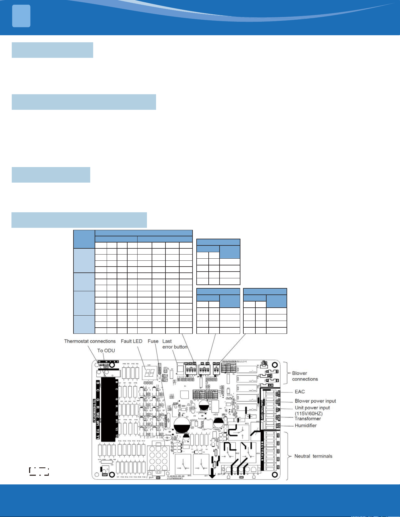
mrcool.com31
ELECTRICAL CONNECTIONS
6
6.5 24-V Wiring
Make eld 24V connections at the 24V terminal strip.
Connect terminal Y as shown for proper cooling operation.
Use only AWG No. 18, color-coded, copper thermostat wire.
6.6 Accessories (Field Supplied)
1. Electronic Air Cleaner (EAC): Connect an accessory Electronic Air Cleaner (if used) using l/4-in female quick connect
terminals to the two male 1/4-in quick-connect terminals on the control board marked EAC-H and NEUTRALS. The
terminals are rated for 115V AC, 1.0 amps maximum and are energized during blower motor operation.
2. Humidier (HUM): Connect an accessory 115V AC, 0.5 amp. maximum humidier (if used) to the 1/4-in male
quick-connect HUM-H terminal and NEUTRALS terminal on the control board. The HUM terminal is energized
when gas valve relay is energized.
6.7 Grounding
The furnace must be electrically grounded in accordance with local codes or, in the absence of local codes, with
the National Electrical Code, ANSI/NFPA 70, and /or the Canadian Electrical Code, CSA C22.1, Part 1, if an external
electrical source is utilized.
6.8 Furnace Control Diagram
80% Unit
Windshield
Setting
Fan Speed
DIP SW Nominal Speed
S3-1 S3-2 S3-3 S3-4 H-Heat L-Heat H-Cool L-Cool
100C/120D
*OFF ON OFF OFF 4 3 3 2
OFF ON ON OFF 4 3 5 3
OFF ON ON ON 5 4 4 4
OFF ON OFF ON 4 3 4 3
80B/80C
*ON OFF OFF ON 5 5 5 4
OFF ON OFF ON 4 3 4 3
OFF ON OFF OFF 4 3 3 2
60B
OFF ON OFF OFF 4 3 3 2
*OFF ON ON OFF 4 3 5 3
OFF ON ON ON 5 4 4 4
OFF ON OFF ON 5 4 4 4
40A
*ON OFF ON ON 5 3 5 4
OFF OFF ON OFF 4 2 3 2
ON ON OFF ON 4 2 4 3
Heat O Delay
DIP SW
Nominal
(Minutes)
S2-1 S2-2
*OFF OFF 90
ON OFF 120
OFF ON 150
ON ON 180
Cool O Delay
DIP SW
Nominal
(Minutes)
S2-3 S2-4
*OFF OFF 60
ON OFF 90
OFF ON 120
ON ON 150
W2 Delay
DIP SW
Nominal
(Minutes)
S1-1 S1-2
OFF OFF *OFF
ON OFF RESERVE
OFF ON RESERVE
ON ON RESERVE
= RESERVED
Figure 6.8a
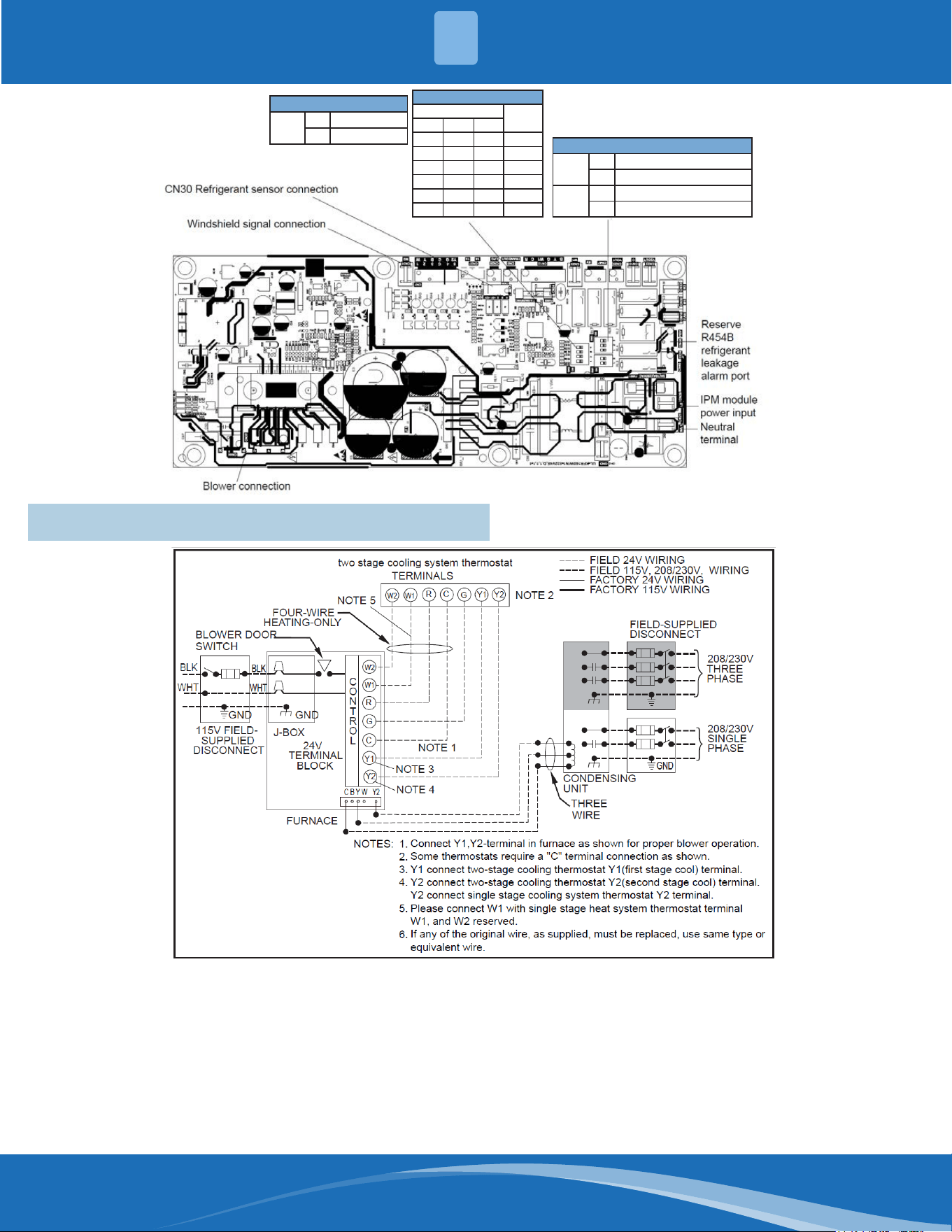
mrcool.com 32
32
ELECTRICAL CONNECTIONS
6
Series of Products
SW2-4
OFF 80% Gas Furnace
ON 96% Gas Furnace
Fan Speed
SW1-1
OFF NORMAL SPEED
ON SLOW SPEED
SW1-2
OFF WITHOUT REFRIGERANT SENSOR
ON WITH REFRIGERANT SENSOR
80% MACHINE TYPE
DIP SW
TYPE
SW2-1 SW2-2 SW2-3
OFF OFF OFF *
OFF OFF ON 40A
OFF ON OFF 60B, 80B
OFF ON ON 80C
ON OFF OFF 100C
ON OFF ON 120D
Notes:
1. Connect Y1/Y2-terminal in furnace as shown for proper blower operation.
2. Some thermostats require a "C" terminal connection as shown.
3. Y1 connect two-stage cooling thermostat Y1 (rst stage cool) terminal. Y/Y2 connect two-stage cooling thermostat
Y2 (second stage cool) terminal.
4. Y1 connect single stage cooling system thermostat Y terminal.
5. Please connect W/W1 with single stage heat system thermostat terminal W and W2 reserved.
6. If any of the original wire, as supplied, must be replaced, use the same type or equivalent wire.
6.9 Wiring Diagram with I-Stage Thermostat
Figure 6.8b
mrcool.com33
ELECTRICAL CONNECTIONS
6
6.10 Refrigerant Leakage Sensor Requirements
WARNING
According to the safety requirements of UL 60335-2-40 on combustible refrigerant A2L, when the gas furnace
is used with a coil, and the new type of combustible refrigerant is used in the coil, the unit must be equipped
with the refrigerant gas detection sensor to monitor the refrigerant concentration around the unit in real time
to prevent the danger of abnormal refrigerant leakage.
Refrigerant gas detection sensors are manufactured under the coil manufacturing label and must be installed
by a qualied local gas supplier, distributor, or service organization.
If the refrigerant gas detection sensor is not installed or is incorrectly installed, it does not meet the
requirements of current regulations and cannot eectively warn of an emergency, which may cause personal
injury. Therefore, follow the instructions provided in the manual.
For the use of a coil unit, please connect the refrigerant gas sensor cable terminal to the CN30 interface,
as shown in Figure 6.8b, and move the drive plate SW1-2 to the "ON" position. Refer to the coil manual for
installation locations of refrigerant gas sensors.
Installation of Refrigerant Detection Sensor
When the sensor detects a refrigerant leak, the unit will respond according to the following rules:
Operation Indication of Refrigerant Gas Sensor
LED2 Number
of Green
Flashes
Fault Location Fault Cause Unit Response & Handling Method
1
The refrigerant
sensor
communication fails.
The communication with the
refrigerant sensor fails for
2 minutes or the refrigerant
sensor is faulty.
The LED2 indicator of the driver board
blinks green once, and the Y signal is
disconnected to stop cooling.
Contact your distributor to check the
sensor.
2
Refrigerant
concentration
exceeds the limit
alarm value.
The pipe is damaged or the
refrigerant leaks.
The green light of the drive board LED2
ashes twice, disconnect the Y signal,
stop the refrigeration, and the fan in
the unit will continue to run until the
refrigerant concentration is detected to
decrease to a safe value.
Maintain ventilation and avoid open
ames. Contact the distributor to check
the unit.
3
Forget the dip
reminder.
The sensor is connected and
communication is normal,
but SW1-2 is in the "OFF"
position.
LED2 of the driver board blinks green
three times.
Check whether SW1-2 is in the ON
position.
4 Expiration reminder
The sensor expires or is
faulty.
The LED2 indicator of the driver board
blinks green four times to turn o the Y
signal and stop cooling.
Contact your distributor for a new
refrigerant detection sensor.
mrcool.com 34
34
START-UP, ADJUSTMENT, & SAFETY CHECK
7
7.1 General Overview
1. Maintain 115V wiring and ground. Improper polarity will result in rapid ashing LED and no furnace operation.
2. Make thermostat wire connections at the 24-V terminal block on the furnace control. Failure to make proper
connections will result in improper operation.
3. Gas supply pressure to the furnace must be greater than 4.5-in. W.C. (0.16 psig ) but not exceed 14-in. W.C.
(0.5 psig).
4. Check all manual-reset switches for continuity.
5. Install blower compartment door. Door must be in place to operate furnace.
6. Replace outer door.
WARNING-FIRE HAZARD
This furnace is equipped with manual reset limit switches in the gas control area. The switches open and shut
o power to the gas valve if a ame rollout or overheating condition occurs in
the gas control area. DO NOT bypass the switches. Correct inadequate combustion air supply problem before
resetting the switches.
CAUTION-CUT HAZARD
• Failure to follow this caution may result in intermittent furnace operation.
• Furnace control must be grounded for proper operation or else control will lock out. Control must remain
grounded through green/yellow wire routed to gas valve and manifold bracket screw.
7.2 Start-Up Procedures
WARNING-FIRE & EXPLOSION HAZARD
Never test for gas leaks with an open ame. Use a commercially available soap solution made
specically for the detection of leaks to check all connections.
1. Purge gas lines after all connections have been made.
2. Check gas lines for leaks.
WARNING-ELECTRICAL SHOCK HAZARD
Blower access door switch opens 115V power to control. No component operation can occur unless switch is
closed. Caution must be taken when manually closing this switch for service purposes.
3. This furnace is also equipped with a self-diagnosing electronic control module. In the event a furnace component is
not operating properly, the control module LED will ash on and o in a factory-programmed sequence, depending
on the problem encountered.
This light can be viewed through the observation window in the blower access door. Refer to the Troubleshooting
Chart for further explanation of the lighting codes.
Follow the start-up and adjustment items, refer to further information in Operational Checks.
mrcool.com35
START-UP, ADJUSTMENT, & SAFETY CHECK
7
7.3 Furnace Start-up
1. Close the manual gas shuto valve external to the
furnace.
2. Turn o the electrical power to the furnace.
3. Set the room thermostat to the lowest possible
setting.
4. Remove the burner compartment door.
NOTE
This furnace is equipped with an ignition device
which automatically lights the burner. Do not try to
light the burner by hand.
5. Gas Valve: Push the switch to the OFF position.
6. Wait ve minutes to clear out any gas. Then smell
for gas, including near the oor.
7. If you do not smell gas after ve minutes. Push the
switch to the ON position.
WARNING-FIRE & EXPLOSION HAZARD
Failure to follow this warning could cause personal
injury, death and/or property damage. Never test for
gas leaks with an open ame. Use a commercially
available soap solution made specically for the
detection of leaks to check all connections.
8. Replace the door on the front of the furnace.
9. Open the manual gas valve external to the furnace.
10. Turn on the electrical power supply to the furnace.
11. Set the room thermostat to the desired temperature.
NOTE
There is an approximate 37 second delay between
thermostat energizing and burner ring.
FURNACE SHUTDOWN
1. Set the thermostat to lowest setting.
2. Turn o the electrical power supply to the furnace.
3. Gas Valve : Push switch to the OFF position.
4. Close manual gas shuto valve external to the
furnace.
5. Replace the door on the unit.
7.4 Sequence of Operation
NOTE
Furnace control must be grounded for proper
operation or control will lock out. Control is
grounded through green wire routed to gas valve
and manifold bracket screw. Follow the sequence of
operation through the dierent modes.
Read and follow the wiring diagram very carefully.
The blower door must be installed for power to be
conducted through the blower door interlock switch ILK
to the furnace control CPU, transformer TRAN, inducer
motor IDM, blower motor BLWM, hot--surface igniter
HSI, and gas valve GV.
1. Heating mode
The wall thermostat “calls for heat,” closing the R--to-
-W1 circuit. The furnace control performs a self-check,
veries the pressure switch contacts PRS are open, and
starts the inducer motor IDM.
a. Inducer Pre-purge Period- The inducer blower
and optional humidier are energized and the
igniter is powered within one second.
The pressure switch contacts PRS close to begin
a 15-second pre-purge period.
b. Igniter Warm-Up- At the end of the pre-purge
period, the Hot-Surface igniter HSI is energized
for a 17-second igniter warm-up period.
This controller has an adaptive algorithm that adjusts
the duration of the igniter warm-up, to extend igniter
life. Upon initial application of power, the warm-up
time is 17 seconds. The igniter on-time will then be
increased or decreased depending on whether or not
ame is achieved. The warm-up time is limited to a
maximum of 27 seconds.
Upon a call for heat, if the warm-up time has not
been locked, it will be decreased by one second. This
reduction of the igniter one time will continue until
ame fails to be achieved (resulting in a retry).
c. Trial-for-Ignition Sequence-- When the igniter
warm-up period is completed, the main gas
valve relay contacts GVR close to energize the
gas valve GV, the gas valve opens for 4
seconds. The gas valve GV permits gas ow
to the burners where it is ignited by
the His, a 4-second ame proving period begins.
d. Flame-Proving--When the burner ame is
proved at the ame-proving sensor electrode
FSE, the furnace control CPU begins the blower-
ON delay period and continues to hold the gas
valve GV open.
mrcool.com 36
36
START-UP, ADJUSTMENT, & SAFETY CHECK
7
If ame is not detected, the gas valve is de-energized, the igniter is turned o, and the furnace control goes into
the “retry” sequence. The “retry” sequence provides a 60-second wait following an unsuccessful ignition attempt
(ame not detected). After this wait, the ignition sequence is restarted with an additional 10 seconds of igniter
warm-up time. If this ignition attempt is unsuccessful, one more retry will be made before the control goes into
system lockout.
If ame is detected, then lost, the furnace control will repeat the initial ignition sequence for a total of two “recycles”.
After two unsuccessful “recycle” attempts, the control will go into system lockout.
If ame is established for more than 10 seconds after ignition, the furnace controller will clear the ignition attempt
(or retry) counter. If ame is lost after 10 seconds, it will restart the ignition sequence. This can occur a maximum
of ve times before system lockout.
e. Blower-On Delay- If the burner ame is proven, the blower motor is energized on high speed 30 seconds
after the gas valve GV is energized. Simultaneously, the electronic air cleaner terminal EAC is energized and
remains energized as long as the blower motor BLWM is energized.
f. Blower-O Delay -When the thermostat is satised, the R--to--W1 circuit is opened, de-energizing the
gas valve G V, stopping gas ow to the burners, The inducer motor IDM will remain energized for a 15-second
post--purge period. Humidier is de-energized. The blower motor BLWM and air cleaner terminal EAC will remain
energized for 90, 120, 150, or 180 seconds (depending on the HEAT-OFF delay selection). The furnace control CPU
is factory-set for a 90-second HEAT-OFF delay.
(All times are in seconds, unless noted otherwise)
* These times will vary depending on option switch position. The control is factory-set at 30 seconds heat delay-to-
fan-on, 90 seconds heat delay-to-fan-o and 60 seconds cool delay-to-fan-o.
Timing Specications
Event Denition
Pre-Purge Time
The period of time intended to allow for the dissipation of any unburned
gas or residual products of combustion at the beginning of a furnace
operating cycle prior to initiating ignition.
15
Igniter Warm-
Up Time
The length of time allowed for the igniter to heat up prior to the initiation
of gas ow.
17
Trial for Ignition
Period (TFI)
The period of time between initiation of gas ow and the action to shut
o the gas ow in the event of failure to establish proof of the supervised
ignition source or the supervised main burner ame.
4
Ignition
Activation
Period (IAP)
The period of time between energizing the main gas valve and
deactivation of the ignition means prior to the end of TFI.
3
Retries
The additional attempts within the same thermostat cycle for ignition
when the supervised main burner ame is not proven within the rst trial
for ignition period.
2 times
Valve Sequence
Period
Valve sequence period equals 4 seconds trial for ignition period x (1 initial
try + 2 retries) + 12 seconds.
12
Inter-purge
The period of time intended to allow for the dissipation of nay unburned
gas or residual products of combustion between the failed trial for
ignition and the retry period.
60
Post-Purge Time
The period of time intended to allow for the dissipation of any unburned
gas for residual products of combustion at the end of a furnace burner
operating cycle. Post-purge begins at the loss of ame sense.
15
Lock-Out Time ANSI standard rated module timing. 300
Heat Delay-To-
Fan-On
The period of time between proof of the supervised main burner ame
and the activation of the blower motor at Heat speed.
30
Table 7.4
mrcool.com37
START-UP, ADJUSTMENT, & SAFETY CHECK
7
7.5 Gas Manifold Pressure Measurement & Adjustment
CAUTION
To prevent unreliable operation or equipment damage, the gas manifold pressure must be as specied on the
unit rating plate. Only minor adjustments should be made by adjusting the gas valve pressure regulator.
This valve is shipped from the factory with the regulator preset.
Consult the appliance rating plate to ensure burner manifold pressure is as specied. If another outlet pressure is
required, follow these steps.
1. Turn OFF all electrical power to the system.
2. Using a 3/32 inch hex wrench, loosen outlet pressure tap (boss) screw one turn. Do not remove screw.
3. Attach a hose and manometer to the potlet pressure boss of valve to over lap at least 3/8”
4. Turn ON system power and set thermostat to a call for heat.
5. Using a leak detection solution or non-chlorine soap suds, check for leaks at hose connection. Bubbles forming
indicate a leak. SHUT OFF GAS AND FIX ALL LEAKS IMMEDIATELY!
6. Remove regulator screw cover. Turn regulator screw either clockwise to increase pressure or counter clockwise
to decrease. Always adjust regulator to provide the correct pressure according to the original equipment
manufacturer specications listed on the appliance rating plate.
7. Replace regulator screw cover and nger-tighten securely.
8. Turn OFF all electrical power to the system.
9. Remove manometer and hose from outlet pressure tap.
10. Tighten outlet pressure tap clockwise 7 in-Lbs minimum to seal port.
11. Turn ON system power and set thermostat to call for heat.
12. Using a leak detection solution or non-chlorine soap suds, check for leaks at hose connection. Bubbles forming
indicate a leak. SHUT OFF GAS AND FIX ALL LEAKS IMMEDIATELY!
2. Cooling Mode
In a typical single stage cooling system (Y connection), a call for cool is initiated by closing the thermostat contacts.
This energizes the compressor and the electronic air cleaner (optional).
The circulator will be energized at cool speed after the COOL delay-to-fan-on period. After the thermostat is
satised, the compressor is de-energized and the COOL delay-to-fan-o period begins. After the COOL delay-to-
fan-o period ends, the circulator and the electronic air cleaner are de-energized.
3. Fan Mode
If the thermostat fan switch is moved to the ON position, the circulator fan (low heat speed) and the electronic air
cleaner (optional) are energized. When the fan switch is returned to the AUTO position, the circulator and electronic
air cleaner are de-energized.
Event Denition
Heat Delay-To-
Fan-O*
The period of time between the loss of a call for heat and the deactivation
of the blower motor at Heat speed.
90/120/150/180
Cool Delay-To-
Fan-On
The period of time after a thermostat demand for cool before energizing
the circulator blower motor at Cool speed.
1
Cool Delay-To-
Fan-O
The period of time between the loss of a call for cool and the deactivation
of the blower motor at Cool speed.
60/90/120/150
Automatic Reset
Time
After one (1) hour of internal or external lockout, the control will
automatically reset itself and go into an auto restart purge for 60 seconds.
60 Minutes
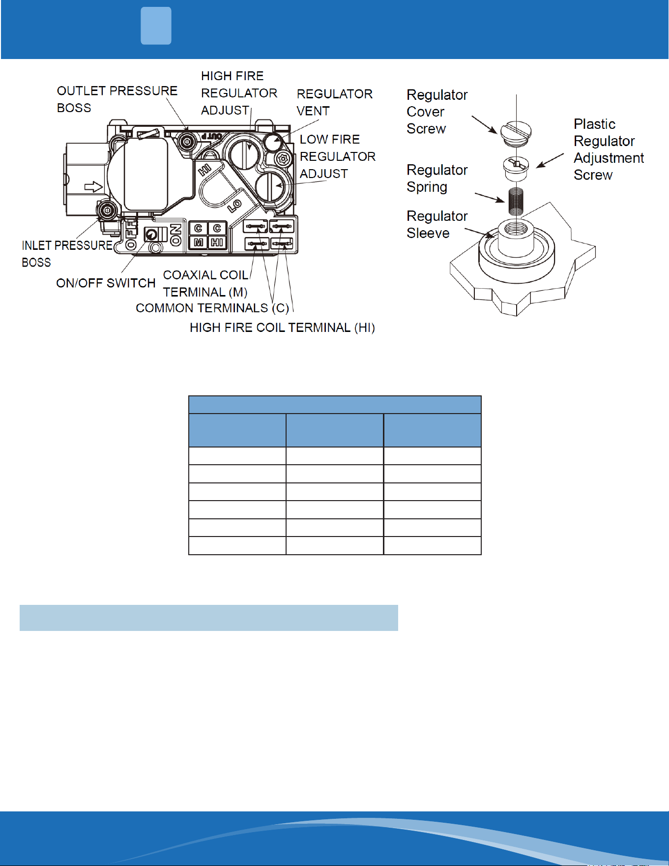
mrcool.com 38
38
START-UP, ADJUSTMENT, & SAFETY CHECK
7
Figure 7.5
Measure gas manifold pressure with burners ring. Adjust manifold pressure per the Manifold Gas Pressure table.
The nal manifold pressure must not vary more than ±0.3 w.c. from specied manifold pressure.
Any necessary major changes in gas ow rate should be made by changing the size of the burner orice.
Table 7.5
Manifold Gas Pressure
Input Rating
KBTU/H
Natural Gas Propane Gas
40A 3.0" W.C. 10.5" W.C.
60B 3.5" W.C. 10" W.C.
80B 3.8" W.C. 10" W.C.
80C 3.9" W.C. 10" W.C.
100C 3.8" W.C. 10" W.C.
120D 3.8" W.C. 10.5" W.C.
7.6 Gas Input Rate Measurement (Natural Gas Only)
The gas input rate to the furnace must never be greater than that specied on the unit rating plate. To measure
natural gas input using the gas meter, use the following procedure.
1. Turn OFF the gas supply to all other gas-burning appliances except the furnace.
2. While the furnace is operating, time and record one complete revolution of the smallest gas meter dial.
3. Calculate the number of seconds per cubic foot (sec/ft3) of gas being delivered to the furnace. If the dial is one
cubic foot dial, divide the number of seconds recorded in step 2 by one. If the dial is a two cubic foot dial, divide
the number of seconds recorded in step 2 by two.
4. Calculate the furnace input in BTUs per hour (BTU/hr). Input equals the installation's gas heating value multiplied
by a conversion factor (hours to seconds) divided by the number of seconds per cubic foot. The measured input
must not be greater than the input indicated on the unit rating plate.
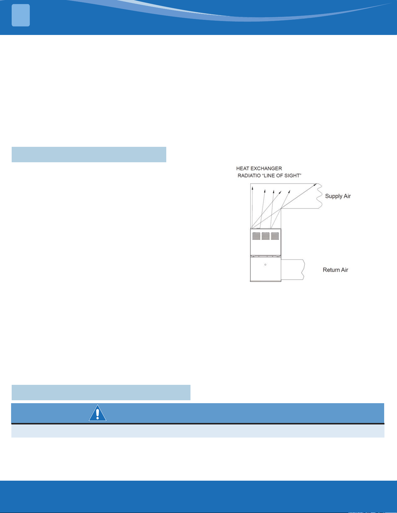
mrcool.com39
START-UP, ADJUSTMENT, & SAFETY CHECK
7
7.7 Temperature Rise Adjustment
Air temperature rise is the temperature dierence
between supply and return air. The proper amount of
temperature rise is usually obtained when the unit is
operated at the rated input with the "as shipped" blower
speed. If the correct amount of temperature rise is not
obtained, it may be necessary to change the blower
speed.
An incorrect temperature rise can cause condensing in or
overheating of the heat exchanger. Determine and adjust
the temperature rise as follows. The temperature rise
must be within the range specied on the rating plate.
Temperature Rise Adjustment
1. Operate furnace with burners ring approximately 15 minutes. Ensure all registers are open and all duct
dampers are in their nal (fully or partially open) position.
2. Place thermometers in the return and supply ducts as close to the furnace as possible. Thermometers must not
be inuenced by radiant heat by being able to "see" the heat exchanger.
3. Subtract the return air temperature from the supply air temperature to determine the air temperature rise.
Allow adequate time for thermometer readings to stabilize.
4. Adjust temperature rise by adjusting the circulator blower speed. Increase blower speed to reduce temperature
rise. Decrease blower speed to increase temperature rise.
7.8 Circulator Blower Speed Adjustment
This furnace is equipped with a ECM circulator blower motor. This blower provides ease in adjusting blower speeds.
The cooling blower speed is shipped set on 5(4). High heat ships on 4(3).These blower speeds should be adjusted
by the installer to match the installation requirements so as to provide the correct heating temperature rise and
the correct cooling CFM.
WARNING-ELECTRICAL SHOCK HAZARD
Turn OFF power to the furnace before changing speed taps.
Figure 7.7
EXAMPLE:
Installation's gas heating (HTG) value: 1,000 BTU/ft3 (Obtained from gas supplier)
Installation's seconds per cubic foot: 34 sec/ft3
Conversion Factor (hours to seconds): 3600 sec/hr
Input = (Htg. value x 3600) + seconds per cubic foot
Input = (1,000 BTU/ft3 x 3600 sec/hr) + 34 sec/ft3
Input = 106,000 BTU/hr
This measured input must not be greater than the input indicated on the unit rating plate.
5. Turn ON gas and relight appliances turned o in step 1. Ensure all the appliances are functioning properly and
that all pilot burners are operating.
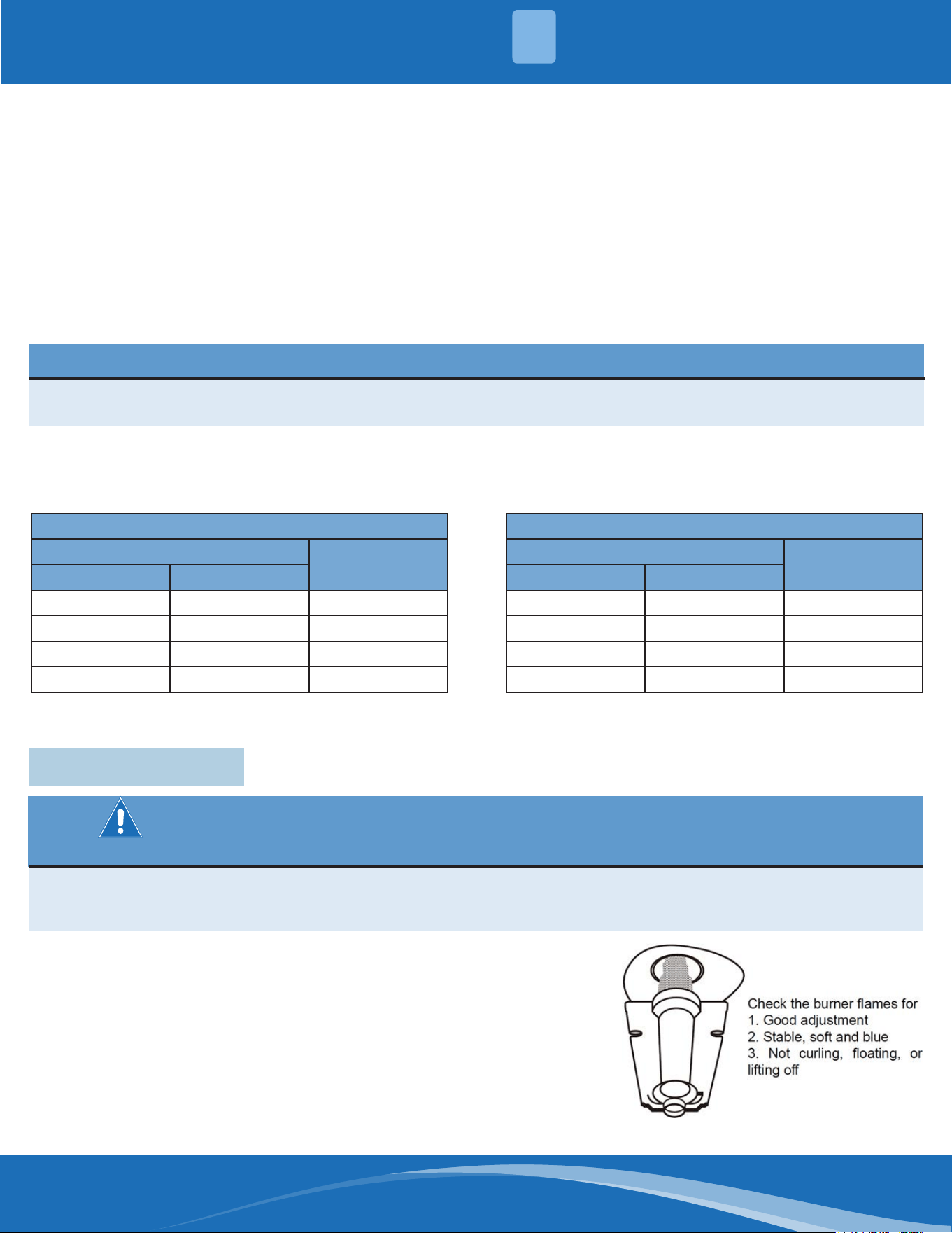
mrcool.com 40
40
Circulator Blower Fan Timing Adjustment
NOTE
Items in this section refer to the air circulator blower fan, NOT to the induced draft blower. The induced draft
blower timing sequence is not adjustable. The circulator blower fan timing is adjustable.
As shipped, the circulator blower fan will remain on for 180 seconds after the gas valve closes. When a call for
cooling occurs, the circulator fan comes on and remains on for 90 seconds after the call for cooling ends. During
normal heating operation, the circulator fan will come on approximately 30 seconds after the gas valve opens.
Heat O Delay
DIP SW
Nominal
(Minutes)
S2-1 S2-2
*OFF OFF 90
ON OFF 120
OFF ON 150
ON ON 180
Cool O Delay
DIP SW
Nominal
(Minutes)
S2-3 S2-4
*OFF OFF 60
ON OFF 90
OFF ON 120
ON ON 150
Table 7.8b
To adjust the circulator blower speed, proceed as follows:
1. Turn o power to the furnace.
2. Select the heating and cooling blower speeds that match the installation requirements from the Air Delivery-
CFM (Without Filter) table.
3. Relocate desired motor leads to the circulator blower heat and cool speed terminals on the integrated control
module. (Terminals are identied as HEAT and COOL (hot)). If heating and cooling blower speeds are the same,
a jumper wire must be used between the heat and cool terminals.
4. Turn ON power to furnace.
5. Verify proper temperature rise as outlined in Temperature Rise section.
8.1 Burner Flame
WARNING-FIRE, EXPLOSION, ELECTRICAL SHOCK, & CARBON
MONOXIDE POISONING HAZARD
Do not remove any internal compartment covers or attempt any adjustment. Electrical compartments are
contained in both compartments. Contact a qualied service agent at once if an abnormal ame appearance
should develop.
The burner ames should be inspected with the burner compartment door
installed. Flames should be stable, quiet, soft, and blue (dust may cause
orange tips but they must not be yellow). Flames should extend directly
outward from the burners without curling, oating, or lifting o, and should
enter heat-exchanger tube.
Flames must not impinge on the sides of the heat exchanger ring tubes.
Figure 8.1
OPERATIONAL CHECKS
8
Table 7.8a
mrcool.com41
SAFETY CIRCUITS
9
9.1 General
A number of safety circuits are employed to ensure safe
and proper furnace operation. These circuits serve to
control any potential safety hazards and serve as inputs
in the monitoring and diagnosis of abnormal function.
These circuits are continuously monitored during
furnace operation by the integrated control module.
9.2 Integrated Control Model
The integrated control module is an electronic device
which controls all furnace operations. Responding to the
thermostat, the module initiates and controls normal
furnace operation, and monitors and addresses all
safety circuits. If a potential safety concern is detected,
the module will take the necessary precautions and
provide diagnostic information through an LED display.
9.3 Primary Limit
The primary limit control is located on the partition
panel and monitors heat exchanger compartment
temperature. It is an automatic reset temperature
sensor. The limit guards against the overheating
resulting from insucient air passing over the heat
exchanger.
9.4 Reverse Flow Switch
The reverse ow switch is located on the air circulating
blower housing. It is an automatic reset temperature
sensor. The reverse ow switch shuts o the furnace
when the air circulating blower fails on downow or
horizontal installations to prevent air lter or other
parts from overheating by hot air.
9.5 Rollout Limits
The rollout limit controls are mounted on the burner/
manifold assembly and monitor the burner ame.
They are manual-reset temperature sensors. This limit
guards against burner ames not being properly drawn
into the heat exchanger.
9.6 Pressure Switches
The pressure switches are normally-open, negative air
pressure activated switches. They monitor the airow
(combustion air and ue products) through the heat
exchanger via pressure taps located on the induced
draft blower. These switches guard against insucient
airow (combustion air and ue products) through the
heat exchanger.
9.7 Flame Sensor
The ame sensor is a probe mounted to the burner/
manifold assembly which uses the principle of ame
rectication to determine the presence or absence of
ame.
WARNING
Failure to replace with proper control could result in
re, explosion or carbon monoxide poisoning.
This appliance uses a NEGATIVE PRESSURE
REGULATED gas control.
Replace ONLY with the same model number or as
specied by the manufacturer.
mrcool.com 42
42
10.1 Electrostatic Discharge (Eso) Precautions
NOTE
Discharge body's static electricity before touching unit. An electrostatic discharge can adversely aect electrical
components.
Use the following precautions during furnace installation and servicing to protect the integrated control
module from damage.
By putting the furnace, the control, and the person at the same electrostatic potential, these steps will help
avoid exposing the integrated control module to electrostatic discharge. This procedure is applicable to both
installed and uninstalled (ungrounded) furnaces.
1. Disconnect all power to the furnace. Do not touch the integrated control module or any wire connected to the
control prior to discharging your body's electrostatic charge to ground.
2. Firmly touch a clean, unpainted, metal surface of the furnace away from the control. Any tools held in a person's
hand during grounding will be discharged.
3. Service integrated control module or connecting wiring following the discharge process in step 2. Use caution
not to recharge your body with static electricity; (i.e. do not move or shue your feet, do not touch ungrounded
objects, etc.). If you come in contact with an ungrounded object, repeat step 2 before touching control or wires.
4. Discharge your body to ground before removing a new control from its container. Follow steps 1 through
3 if installing the control on a furnace. Return any old or new controls to their containers before touching any
ungrounded object. The primary limit control is located on the partition panel.
10.2 Diagnostic Chart
Refer to the troubleshooting chart on the following pages for assistance in determining the source of unit operational
problems.
The red diagnostic LED blinks to assist in troubleshooting the unit.
The number of blinks refer to a specic code.
10.3 Resetting From Lockout
Furnace lockout results when a furnace is unable to achieve ignition after three attempts. It is characterized by a
non-functioning furnace and a one ash diagnostic LED code from the red LED. If the furnace is in "lockout", it will
(or can be) reset in any of the following ways.
1. Automatic reset: The integrated control module will automatically reset itself and attempt to resume normal
operations following a one hour lockout period.
2. Manual power interruption: Interrupt 115 volt power to the furnace for 1 - 20 seconds.
3. Manual thermostat cycle: Lower the thermostat so that there is no longer a call for heat for 1 - 20 sec.
NOTE
If the condition which originally caused the lockout still exists, the control will return to lockout. Refer to the
diagnostic chart for help in determining the cause.
WARNING-FIRE, EXPLOSION, AND ASPHYXIATION HAZARD
Failure to replace with proper control could result in re, explosion or carbon monoxide poisoning.
This appliance uses a NEGATIVE PRESSURE REGULATED gas control.
Replace ONLY with the same model number or as specied by the manufacturer.
TROUBLESHOOTING
10
mrcool.com43
TROUBLESHOOTING
10
Troubleshooting Chart
Error Code Error/Condition Comments/Troubleshooting
FE Gas valve relay stuck closed
Verify the gas valve is operating and shutting down properly.
Flame in burner assembly should extinguish promptly at the
end of the cycle.
Check orices and gas pressure
E1 Shorted Pressure
Pressure switch is stuck closed. Check switch function, verify
inducer is turning o.
E2 Open Pressure
Check pressure switch function and tubing. Verify inducer is
turning on the pulling-sucient vacuum to engage switch.
E4 Open-Pressure Switch Locked
If the pressure switch cycles 15 times (open, closed) during one
call for heat from the thermostat the control will lockout. Check
pressure switch for uttering, inconsistent closure, or poor
vacuum pressure.
E5
Open thermal limit, rollout
switch
Verify continuity through rollout switch, primary limit, reverse
ow limit circuit.
E6
Open thermal limit, rollout
switch (after 5 times)
E7 Ignition failure locked
Failure to sense ame is often caused by carbon deposits on
the ame sensor, a disconnected or shorted ame sensor lead,
or a poorly grounded furnace. Carbon deposits can be cleaned
with emery cloth.
Verify sensor is not contacting the burner and is located in a
good position to sense ame. Check sensor lead for shorting
and verify furnace is grounded properly.
E8 Flame loss locked
Check items for exceeded retries listed above and verify valve
is not dropping out allowing ame to be established and then
lost.
FL Flame Low
Low ame sense current is often caused by carbon deposits on
the ame sensor, a poorly grounded furnace or a misaligned
ame-sense probe. Carbon deposits can be cleaned with emery
cloth. Check for improve furnace and module ground. Verify
sensor is located in or very near ame as specied by the
appliance manufacturer.
Pr Power reversed
Verify the control and furnace are properly grounded. Check
and reverse polarity (primary) if incorrect.
Fo Fuse open Replace fuse of electric control board.
bE Board error Replace electric control board.
nL Signal error Ensure the wire control signal refer to user manual.
1. Integrated control module will automatically attempt to reset from lockout after one hour.
2. LED Flash code will cease if power to the control module is interrupted through the disconnect or door switch.
Table 10.3
mrcool.com 44
44
WARNING-ELECTRICAL SHOCK, FIRE, OR EXPLOSION HAZARD
Improper servicing could result in dangerous operation, serious injury, death or property damage.
• Before servicing, disconnect all electrical power to furnace.
• When servicing controls, label all wires prior to disconnecting. Reconnect wires correctly.
• Verify proper operation after servicing.
WARNING-FIRE, EXPLOSION, OR CARBON MONOXIDE HAZARD
Failure to replace with proper control could result in re,explosion or carbon monoxide poisoning.
This appliance uses a NEGATIVE PRESSURE REGULATED gas control.
Replace ONLY with the same model number or as specied by the manufacturer.
11.1 Annual Inspection
The furnace should be inspected by a qualied installer or service agency at least once per year. This check should
be performed at the beginning of the heating season. This will ensure that all furnace components are in proper
working order and that the heating system functions appropriately. Pay particular attention to the following items.
Repair or service as necessary.
(a) All ue gas carrying areas external to the furnace (i.e. chimney, vent connector) are clear and free of obstructions.
(b) The vent connector is in place, slopes upward, and is physically sound without holes or excessive corrosion.
(c) The return-air duct connection(s) is physically sound, is sealed to the furnace casing, and terminates outside the
space containing the furnace.
(d) The physical support of the furnace is sound without sagging, cracks, gaps, etc, around the base so as to provide
a seal between the support and the base.
(e) There are no obvious signs of deterioration of the furnace.
(f) The pilot and burner ames are in good adjustment (by comparison with pictorial sketches or drawings of the
main burner ame and, if applicable, the pilot burner ame).
11.2 Filters
A return air lter is not supplied with this furnace; however, there must be a means of ltering all of the return air.
The installer will supply lter(s) at the time of installation.
Filter Maintenance
Improper lter maintenance is the most common cause of inadequate heating or cooling performance. Filters
should be cleaned (permanent) or replaced (disposable) every one month or as required.
When replacing a lter, it must be replaced with a lter of the same type and size.
Become familiar with lter location and procedures for removal, cleaning and replacing them. If help is needed,
contact the installer of the furnace or a qualied servicer.
Filter Removal
Depending on the installation, diering lter arrangements can be applied. A media air lter or electronic air
cleaner can be used as an alternate lter.
Follow the lter sizes given in the Recommended Minimum Filter size table to ensure proper unit performance.
For further details, see your distributor.
SERVICE & MAINTENANCE PROCEDURES
11
mrcool.com45
SERVICE & MAINTENANCE PROCEDURES
11
Upright Filter Removal
To remove lters from an external lter rack in an upright upow installation, follow the directions provided with
external lter rack kit.
Clean, wash and dry a permanent lter. When using a permanent lter, both sides should be sprayed with a dust
adhesive as recommended on the adhesive container. Spray adhesives for use with permanent lters can be found
at some hardware stores.
BE SURE AIRFLOW DIRECTION ARROW POINTS TOWARDS THE BLOWER.
Inspect lter. If your dirty lter is the disposable type, replace dirty lter with the same type and size lter. If your
dirty lter is a permanent lter, clean as follows:
• Wash, rinse, and dry the permanent lters. Both sides should then be sprayed with a lter adhesive as is
recommended on the adhesive container. Many hardware stores stock spray adhesives for use with permanent
lters.
• If badly torn or uncleanable, these lters must be replaced by equal size permanent, high velocity lters. Throwaway
lters must not be used as replacement for permanent lters. Under normal use, permanent lters should last for
several years.
11.3 Induced Draft & Circulating Blower Motors
The bearings in the induced draft blower and circulator blower motors are permanently lubricated by the
manufacturer. No further lubrication is required. Check motor windings for accumulation of dust which may cause
overheating. Clean as necessary.
11.4 Flame Sensor
*To be checked by a qualied servicer only*
Under some conditions, the fuel or air supply can create a nearly invisible coating on the ame sensor. This coating
acts as an insulator causing a drop in the ame sense signal. If the ame sense signal drops too low, the furnace will
not sense ame and will lock out. The ame sensor should be carefully cleaned by a qualied servicer using emery
cloth or steel wool. Following cleaning, the ame sense signal should be 1 to 6 microamps at 115 volts.
Igniter
*To be checked by a qualied servicer only*
If the igniter and the surrounding air are at about 70°F and the igniter wires are not connected to any other electrical
components, the resistance of the igniter should not exceed 200 ohms. If it does, the igniter should be replaced.
11.5 Burners
WARNING-FIRE, EXPLOSION, ELECTRICAL SHOCK, AND CARBON
MONOXIDE HAZARD
To avoid personal injury or death, do not remove any internal compartment covers or attempt any
adjustment. Electrical compartments are contained in both compartments. Contact a qualied service agent at
once if an abnormal ame appearance should develop.
Periodically during the heating season, visually check the burner ames. Turn the furnace on at the thermostat.
Wait a few minutes, since any dislodged dust will alter the normal ame appearance. Flames should be stable,
quiet, soft and blue with slightly orange tips. They should not be yellow. They should extend directly outward from
the burner ports without curling downward, oating or lifting o the ports.
NOTE
Only a qualied contractor, installer, or service agency should clean the burners if the burners get a heavy
accumulation of soot and carbon.
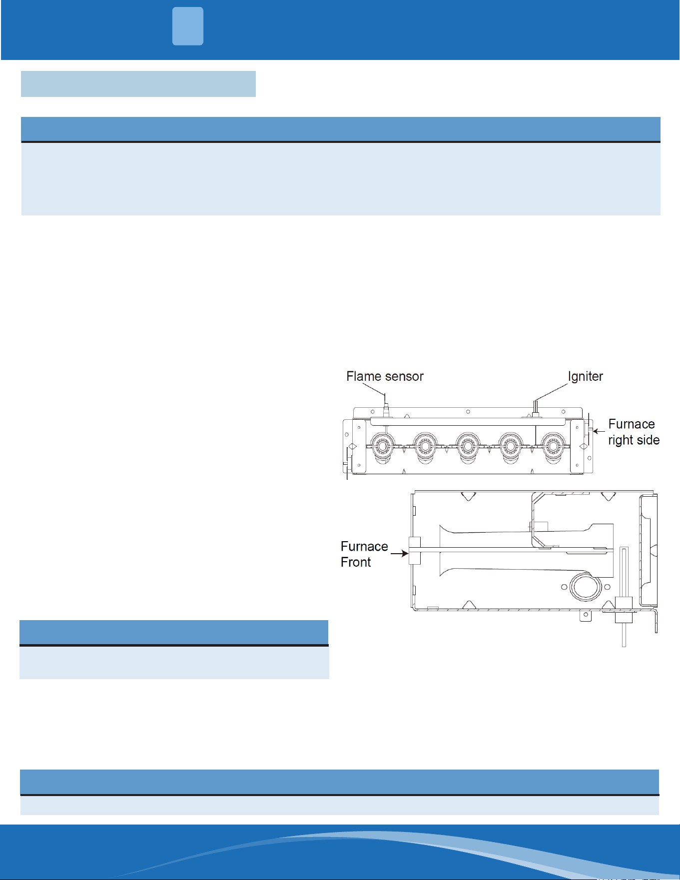
mrcool.com 46
46
SERVICE & MAINTENANCE PROCEDURES
11
11.6 Cleaning Heat Exchanger
The following steps should be performed by a qualied service agency:
NOTE
If the heat exchangers get a heavy accumulation of soot and carbon, they should be replaced rather than
trying to clean them thoroughly. A heavy build-up of soot and carbon indicates that a problem exists which
needs to be corrected, such as improper adjustment of manifold pressure, insucient or poor quality
combustion air, incorrect size or damaged manifold orice(s), improper gas, or a restricted heat exchanger.
Action must be taken to correct the problem.
If it becomes necessary to clean the heat exchangers because of dust or corrosion, proceed as follows:
1. Turn OFF gas and electrical power to furnace.
2. Remove outer access door.
3. Disconnect vent connector from furnace vent elbow.
4. For downow or horizontal furnace having an internal vent pipe, remove internal vent pipe within the casing.
5. Disconnect wires to the following components. Mark wires to aid in reconnection of (be careful when
disconnecting wires from switches because damage may occur):
a. Draft safeguard switch
b. Inducer motor
c. Pressure switch(es)
d. Limit over-temperature switch
e. Gas valve
f. Hot surface igniter
g. Flame-sensing electrode
h. Flame rollout switches
NOTE
Be very careful when removing burner assembly to
avoid breaking igniter.
9. Using eld-provided 25-caliber rie cleaning brush, 36-in. (914 mm) long, 1/4" diameter steel spring cable, a
variable speed, reversible electric drill, and vacuum cleaner, clean cells as follows:
a. Remove metal screw tting from wire brush to allow insertion into cable.
b. Insert the twisted wire end of brush into the end of spring cable, and crimp tight with crimping tool or
crimp by striking with ball-peen hammer. TIGHTNESS IS VERY IMPORTANT.
6. Remove screws that fasten the collector box
assembly to the cell panel. Be careful not to
damage the collector box. Inducer assembly and
elbow need not be removed from collector box.
7. Disconnect gas line from gas manifold.
8. Remove the 5 screws that attach the burner
assembly to the cell panel. The gas valve and
individual burners do not need to be removed
from support assembly.
Figure 11.6a
NOTE
The materials needed in item 9 can usually be purchased at local hardware stores.
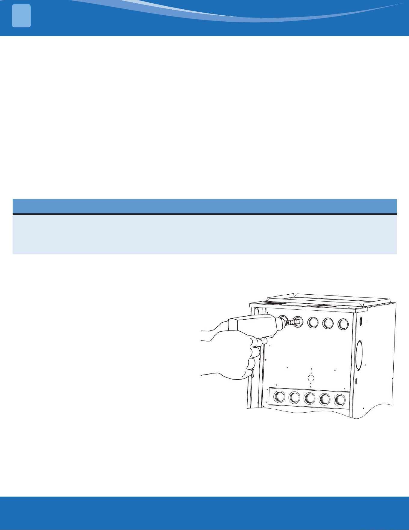
mrcool.com47
SERVICE & MAINTENANCE PROCEDURES
11
1. Attach variable-speed, reversible drill to the end of spring cable (end opposite brush).
2. Insert brush end of cable into the outlet opening of cell and slowly rotate with drill. DO NOT force cable. Gradually
insert cable into upper pass of cell.
3. Work cable in and out of cell 3 or 4 times to obtain sucient cleaning. DO NOT pull cable with great force.
Reverse drill and gradually work cable out.
4. Insert brush end of cable in burner inlet opening of cell, and proceed to clean 2 lower passes of cell in same
manner as upper pass.
5. Repeat foregoing procedures until each cell in furnace has been cleaned.
6. Using vacuum cleaner, remove residue from each cell.
7. Using vacuum cleaner with soft brush attachment, clean burner assembly.
8. Clean ame sensor with ne steel wool.
9. Reinstall burner assembly. Center burners in cell openings.
10. Remove old sealant from cell panel and collector box ange.
11. Spray releasing agent on the heat exchanger cell panel where collector box assembly contacts cell panel.
NOTE
A releasing agent such as cooking spray or equivalent (must not contain corn or canola oil, aromatic or
halogenated hydrocarbons or in+ seal may occur) and RTV sealant (G.E. 162, 6702, or Dow-Corning 738) are
needed before starting installation. DO NOT substitute any other type of RTV sealant. G.E. 162 (P771-9003) is
available through RCD in 3-oz. tubes.
12. Apply new sealant to ange of collector box and attach to cell panel using existing screws, making sure all
screws are secure.
13. Reconnect wires to the following components. (Use connection diagram on wiring label, if wires were not marked
for reconnection locations.):
a. Draft safeguard switch.
b. Inducer motor.
c. Pressure switch(es).
d. Limit over-temperature switch.
e. Gas valve.
f. Hot surface igniter.
g. Flame-sensing electrode.
h. Flame rollout switches.
Figure 11.6b
14. Reinstall internal vent pipe, if applicable.
15. Reinstall vent connector on furnace vent elbow.
Securely fasten vent connector to vent elbow with 2
eld-supplied, corrosion-resistant, sheet metal screws
located 1800 apart.
16. Replace blower access door only, if it was removed.
17. Set thermostat above room temperature and check furnace for proper operation.
18. Verify blower airow and speed changes between heating and cooling.
19. Check for gas leaks
20. Replace outer access door.
mrcool.com 48
48
SERVICE & MAINTENANCE PROCEDURES
11
WARNING-FIRE, OR EXPLOSION HAZARD
Never use a match or other open ame to check for gas leaks. Use a soap-and-water solution.
21. Turn on electric power and gas supply to the furnace.
22. Check furnace for proper operation. Refer to "Operational Checks" section to verify burner ame characteristics.
11.7 Before Leaving an Installation
• Cycle the furnace with the thermostat at least three times. Verify cooling and fan only operation.
• Review the Owner's Manual with the homeowner and discuss proper furnace operation and maintenance
• Leave literature packet near furnace.
11.8 Repair & Replacement Parts
• When ordering any of the listed functional parts, be sure to provide the furnace model, manufacturing, and
serial numbers with the order.
• Although only functional parts are shown in the parts list, all sheet metal parts, doors, etc. may be ordered by
description.
• Parts are available from your distributor.
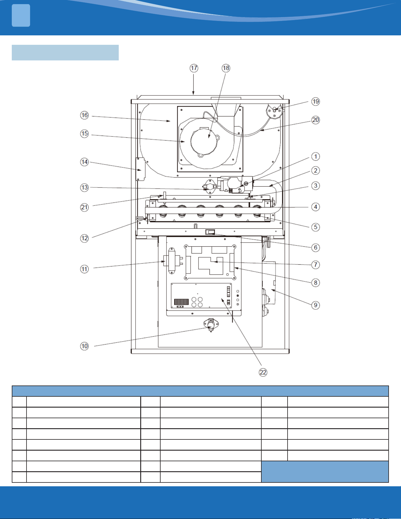
mrcool.com49
SERVICE & MAINTENANCE PROCEDURES
11
Component Identication
1 Gas Valve 9 Circulator Blower 17 Heat Exchanger
2 Gas Manifold 10 Reverse Flow Switch 18 Blower Wheel
3 Mini Igniter 11 Transformer 19 Pressure Switch
4 Natural/Propane Gas Orice 12 Rollout Limit Switch 20 Pressure Switch Hose
5 Burner 13 Primary Limit Switch 21 Flame Sensor
6 Door Switch 14 Junction Box 22 IPM Module
7 Integrated Control Module 15 Induced Draft Blower
8 24 Volt Thermostat Connections 16 Flue Collector Box
11.9 Wiring Diagrams
Figure 11.8
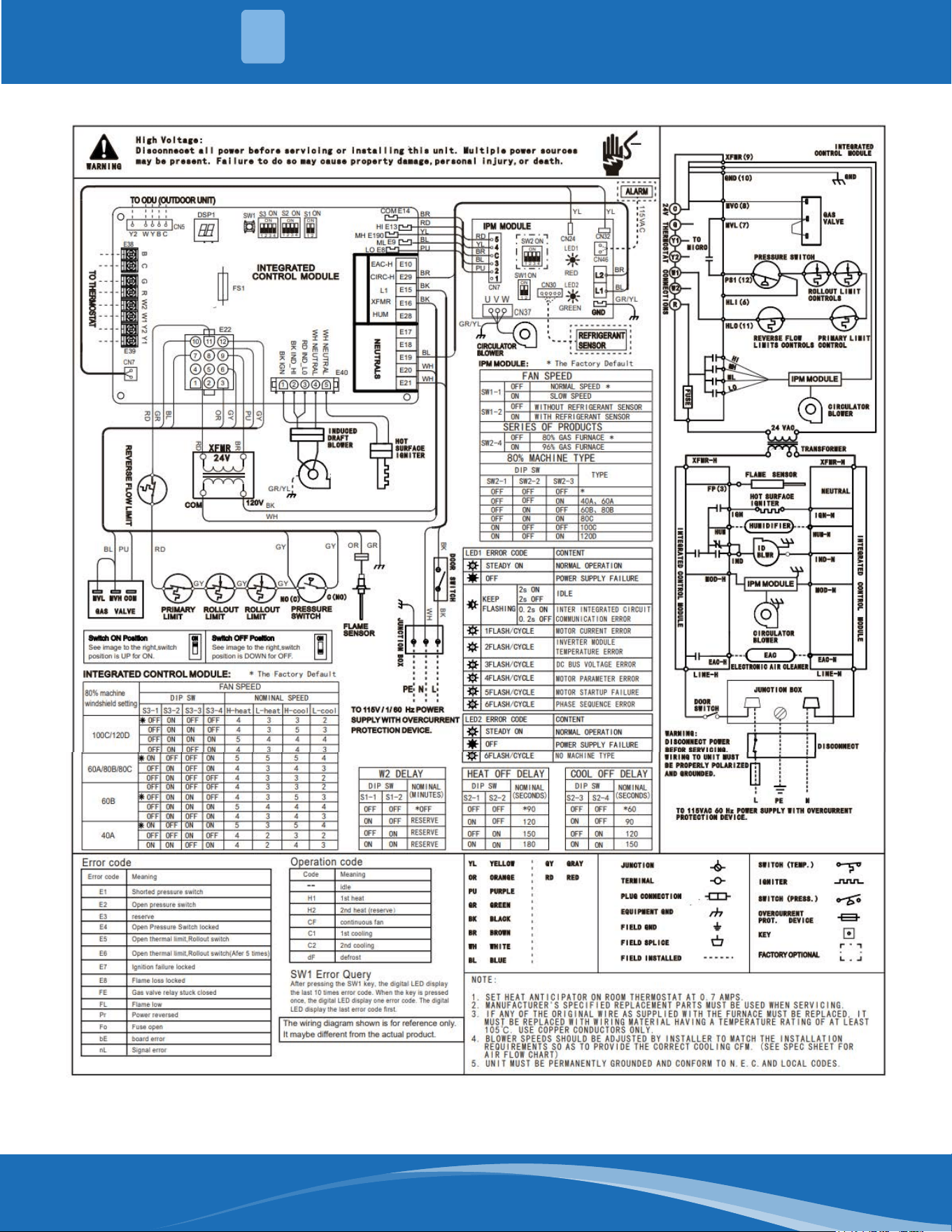
mrcool.com 50
50
SERVICE & MAINTENANCE PROCEDURES
11

VersaPro™
80% Gas Furnace
Installation Manual
The design and specications of this product and/or manual are subject to change without prior notice.
Consult with the sales agency or manufacturer for details.