
2
Warning & Safety
PLEASE READ AND FOLLOW INSTRUCTIONS BELOW TO PREVENT
INJURY OR DAMAGE TO THE PRODUCT
BakeMax® (a registered trademark of Titan Ventures International Inc or TVI) is
not responsible for any harm or injury caused due to any person’s improper or
negligent use of this equipment. The product shall only be operated by someone
over the age of 18, of sound mind, and not under the influence of any drugs or
alcohol, who has been trained in the correct operation of this machine, and is
wearing authorized, proper safety clothing. This machine is intended for
commercial use only. Any modification or miss use to the machine voids any
warranty and may cause harm to individuals using the machine or around the
machine while in operation.
• When using the machine, please ensure that you have read all the
instructions within this manual.
• Be aware of your surroundings when using this machine, ensure there
are no children or any other persons who are near the machine before
operating.
• Do not put hand near moving parts.
• Remove all obstacles, which may interfere with machine functions.
• Keep work area clean and clear of clutter.
• Do not sit or stand on machine.
• Do not wear loose clothing or jewelry when operating machine as it may
get caught in moving parts and cause injury.
• Stop using the machine and have it checked by an authorized service
personal if it is not working properly.
• Disconnect from power source before performing and maintenance or
cleaning on the machine.
• When the machine is not in use, please clean and store properly,
• Do not place any electrical parts or plug / cord in water or liquid.
• If the supply cord is damaged it must be replaced by an authorized
service agent to avoid any electrical hazards.
• Keep power cord away from heat.
• Always ensure to follow local laws when operating your machine.
3
GENERAL INFORMATION
Before installing the appliance, read operation and maintenance instructions carefully. Wrong
installation and part changing may damage the product or may cause injury to people. These
are not in our company’s responsibility to damage the appliance intentionally, negligence,
detriments because of disobeying instructions and regulations, wrong connections,
unauthorized intervention to appliance invalidates the warranty.
1. This instruction manual should be kept in a safe place for future reference.
2. Installation should be made in accordance with the ordinances and security rules of that
country by qualified service personnel.
3. This appliance must be used by a trained person.
4. Please turn off the appliance immediately in the event of malfunction or failure. The
appliance should be repaired only by authorized service personnel. Please demand
original spare part.
WARNING:
• Improper installation, adjustment, modification, service or maintenance can result in
property damage, injury or death. Read the installation, use and maintenance
instructions before installing or servicing this equipment.
• This device must be installed in accordance with applicable legislation and should
only be used in a well-ventilated area. Please refer to the instructions before installing
and using this device.
SAFETY SYMBOLS
These symbols are intended to alert the user to the presence of important
operating and maintenance instructions in the manual accompanying the
appliance.
WARNING :The device must be used by trained personnel.
4
SERVICE AND MAINTENANCE
Contact your local authorized service agent for service or required maintenance.
Please record the model number, serial number, voltage and purchase date in the area below
and have it ready when you call to ensure a faster service.
Model No.
BMDN151USA4
Serial No.
Voltage
Purchase Date
Authorized Service Agent Listing Reference the listing provided with the unit or for an updated
listing go to:
Website: www.BakeMax.com
E-mail: [email protected]
Service Help Desk
Company
BakeMax
Website
www.BakeMax.com
Phone
(800) 565-2253
Fax
(506) 859-6929
Address
20 Caribou St, Moncton, NB E1H 0P3
Note: Make sure that all paper protection and packaging have been removed before
operating the device.
5
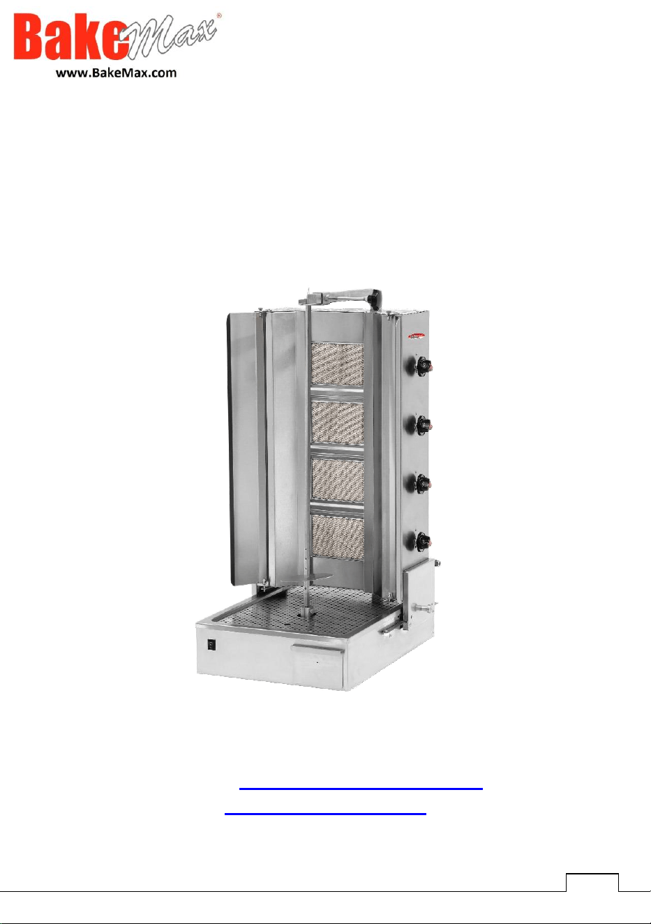
PRODUCT DESCRIPTION
* This device, w
h
ic
h
p
r
o
vi
de
s
h
i
gh
e
ffici
en
cy, is
a
pro
f
e
ssi
ona
l s
hawa
rm
a
m
a
c
hine
p
r
odu
c
ed
fo
r
us
e in in
du
stri
a
l kitc
hen
s.
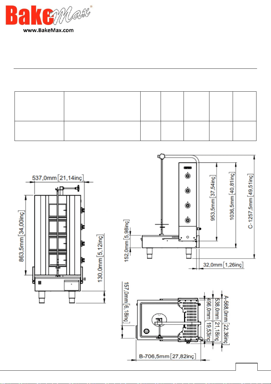
Model #
Electrical
Width
Depth
Height
Product
Weight
Crated
Weight
BMDN151USA4
110V / 60Hz / Nema 5-15P
22.4”
28”
49.5”
90lbs.
101lbs.

6
TRANSPORT
• T
h
is device ca
nno
t
be
handh
el
d
. T
here
f
ore
,
u
s
e
a
f
or
klift t
ru
ck (f
o
rk
li
ft
o
r
palle
t tr
u
ck)
t
o
tr
an
s
po
rt t
he
devic
e
. (The lift
a
rms
o
f t
he
f
o
rklift
or
pa
ll
e
t t
ru
ck s
hou
l
d
rea
c
h
m
o
r
e
t
han
hal
f
wa
y fr
o
m t
he
bo
tt
o
m
o
f the
de
vice).
UNPACKING
• T
h
e
d
evice s
hou
l
d
be
opene
d,
and
its
pa
ck
ag
i
ng
s
hou
l
d
be
de
str
o
y
ed
a
cc
o
r
ding
t
o
t
he
r
egula
t
ion
s
o
f the country of
u
s
e
. F
ood
c
on
tact
par
ts
are
st
a
i
n
l
e
ss st
ee
l. All
pla
st
i
c
pa
rts
a
r
e
m
a
rk
ed
wi
t
h
t
he
sym
bol
of t
he
materia
l
.
• C
h
eck that the
pa
rts
o
f t
he
d
evic
e
are
c
omp
l
e
t
e
and
no
t
dam
a
ged
du
r
ing
tr
an
s
po
rt
a
t
ion
.
ASSEMBLY
• Plac
e
the pro
du
ct
on
a
fl
a
t
an
d s
o
li
d
s
ur
f
a
c
e
, t
a
k
e
t
he
ne
c
e
ss
a
ry
p
r
e
c
au
t
ion
s
again
st t
he
r
i
sks
o
f ti
p
pi
n
g.
• T
h
e
p
ersonnel w
ho
will
p
r
o
vid
e
i
n
st
a
ll
a
ti
on
and
s
er
vic
e
t
o
t
he
d
e
v
i
c
e
m
u
st
be
e
x
pe
rts
in
t
hei
r f
ield
s and
h
ave an inst
a
ll
a
ti
on
-s
e
rvic
e
lic
en
s
e
b
y
our
c
ompan
y.
• C
o
nnection to t
he
e
l
e
ctric
a
l
po
w
er
s
upp
ly
mu
st
be
made
b
y
a
quali
f
ied
pe
rs
on
.
• M
a
ke sure th
a
t t
he
v
o
lt
age
t
o
w
h
ic
h
y
ou
c
onne
ct t
he
de
vic
e
is t
he
s
a
m
e
a
s t
he
v
ol
t
age
v
alue
w
r
i
tt
en
on the device
labe
l.
• The gro
und
i
ng
c
onne
cti
on
o
f t
he
de
vic
e
mu
st
be
made
i
n
a
cc
o
r
dan
c
e
wi
t
h
t
he
st
anda
r
d
s
and
saf
e
ty rules.
• T
h
e
g
roundin
g
o
f t
he
de
vic
e
m
u
st
be
c
onne
ct
ed
t
o
t
he
groun
d
ing
line
on
t
he
c
lo
s
e
st
panel
o
f t
he
elect
r
ical install
a
ti
on
.
• D
e
vice electric
a
l c
onne
cti
on
, m
a
i
n
f
u
s
e
and
re
si
dua
l c
urren
t f
u
s
e
m
u
st
be
m
ade
a
cc
o
r
ding
t
o
c
u
rr
en
t
r
eg
u
lations and r
u
l
e
s.
• T
h
e
d
evice m
u
st
be
c
onne
ct
ed
i
n
a
cc
ordan
c
e
wit
h
t
he
na
ti
on
a
l
and
lo
c
al
ga
s
st
anda
r
d
s
o
f t
he
r
el
e
vant count
r
y.
•
De
v
i
c
e
ga
s inl
e
ts
a
r
e
i
nd
ic
a
t
e
d
on
t
he
bod
y wit
h
t
he
“
G
”
l
abe
l.
• C
o
nnection to
ga
s i
n
st
a
ll
a
ti
o
n s
hou
l
d
be
done
wit
h
me
t
a
l fl
e
x
pipe
o
f s
ui
t
able
dia
m
e
t
e
r
and
ball
valv
e
. The said
ba
ll v
a
lv
e
s
ho
ul
d
be
fix
ed
i
n
a
p
l
a
c
e
a
w
a
y f
rom
hea
t
and
ea
s
il
y
a
cc
e
ss
ible
in
c
a
s
e
o
f danger. After t
he
ga
s i
n
l
e
t c
onne
cti
on
is
made
,
po
ssi
b
l
e
ga
s l
ea
ks s
hould
be
c
he
ck
ed
.
• According to t
he
da
t
a
on
t
he
d
e
vic
e
i
n
f
orma
ti
on
p
l
a
t
e
,
ga
s
an
d
p
r
e
ss
u
r
e
m
u
st
be
adju
st
ed
. If t
he
ga
s type t
h
e devic
e
is
ad
j
u
st
ed
f
o
r is
no
t s
u
it
ab
l
e
f
or
t
he
ga
s ty
pe
a
t
t
he
in
st
alla
t
ion
s
i
t
e
, f
ollow
t
he
w
r
i
tt
en
in
s
t
ru
ctions fo
r
ad
j
u
sti
ng
it f
o
r a
d
iff
eren
t
ga
s
ty
pe
.
(
S
ub
j
e
ct: G)
• If t
he
p
l
a
c
e
w
he
r
e
D
öne
r C
oo
k
er
s
are
l
o
c
a
t
ed
is c
o
v
ered
wit
h
non
-c
o
m
bu
st
ible
hea
t
in
s
ula
t
ion
mat
er
ial, the dist
an
c
e
be
tw
ee
n t
hem
s
hou
l
d
be
5
c
m
. Ot
her
wise,
i
t s
hould
be
a
t
lea
st
20
cm. O
pe
r
a
t
e
the
de
vice und
e
r t
he
hood
.
7
GENERAL WARNINGS

8
The
installation
of
the
Appliance
must
conform
to
the NATIONAL
FUEL
GAS
CODE
"ANSI
Z223.1
-
LATEST
EDITION"
AND
ALL
LOCAL
GAS
COMPANY
RULES
AND REGULATIONS.
IN
CANADA
INSTALLATION
SHALL
BE
IN
ACCORDANCE
WITH
THE
CURRENT
CAN/CGA-B149.1
NATURAL
GAS
INSTALLATION
CODE
National
Fuel
Gas
Code,
ANSI
Z223.1/NFPA
54,
or
the
Natural
Gas
and,
CSA
B149.1,
as
applicable,
including:
1)
The
appliance
and
its
individual
shutoff
valve
must
be
disconnected
from
the
gas
supply
piping
system
during
any
pressure
testing
of
that
system
at
test
pressures
more than
1/2
psi
(3.5
kPa).
2)
The
appliance
must
be
isolated
from
the
gas
supply
piping
system
by
closing
its
individual
manual
shutoff
valve during
any
pressure
testing
of
the
gas
supply
piping
system
at
test
pressures
equal
to
or
less
than
1/2
psi
(3.5
kPa).
If you smell
ga
s,
c
all t
he
gas emergency s
er
vic
e
i
mmedia
t
el
y. U
n
t
i
l t
h
e
Servic
e
T
ea
m
a
rriv
e
s do
n
ot use
e
l
e
ctric
a
l
app
li
a
nc
e
s
or
switc
he
s, do
n
ot
light ci
ga
r
e
tt
e
s
o
r matc
he
s, leave door
s
and
wi
ndo
ws as t
he
y
are,
go
o
utside
FOR YOUR SAFETY:
Do
no
t us
e
or
st
ore
ga
s
o
li
ne
or
o
t
her
fl
a
mm
able
ga
s
o
r
liquid
in
t
he
de
v
i
c
e
.
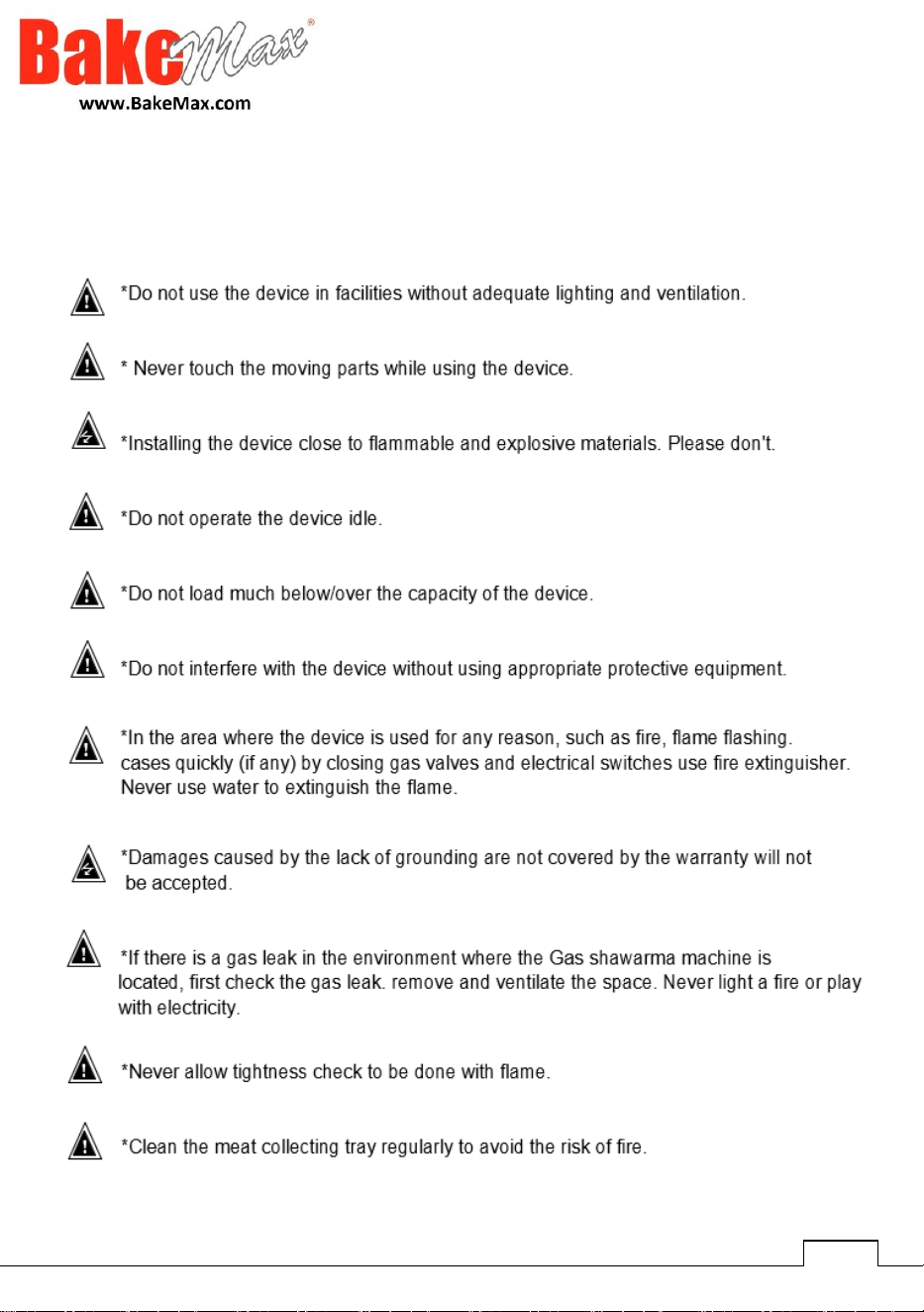
SAFETY SYMBOLS
T
he
s
e
sym
bo
ls
are
i
n
t
ended
t
o
a
l
er
t t
he
u
s
e
r t
o
t
he
p
r
e
s
en
c
e
o
f
i
m
po
rt
an
t
ope
r
a
ti
ng
and
ma
i
n
t
enan
c
e
i
n
st
ru
cti
on
s i
n
t
he
m
anual
a
cc
o
m
pan
y
ing
t
he
app
li
an
c
e
.
9
10
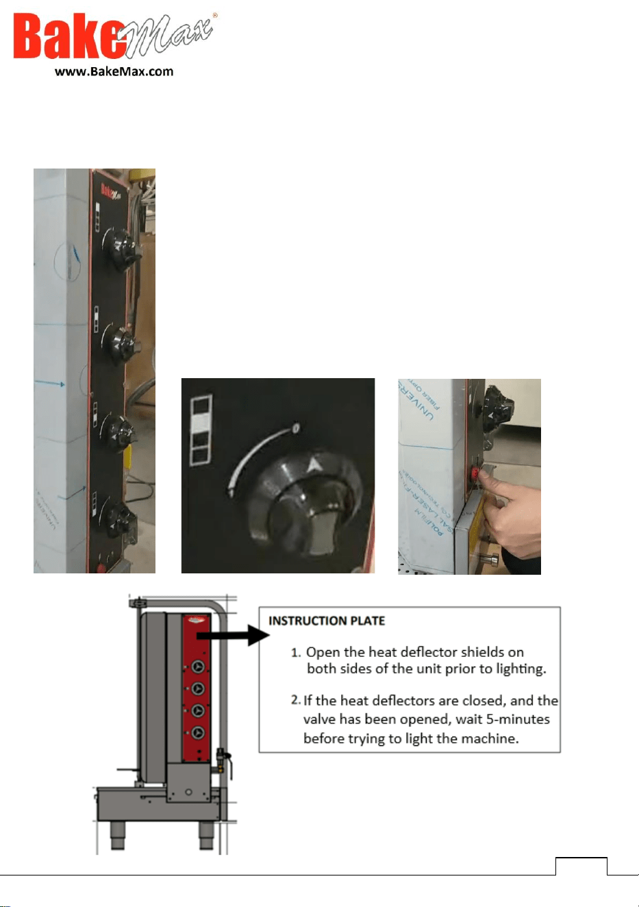
Control Panel
To the top-left of each knob, there is a diagram
corresponding to which burner you will be giving gas to.
Turn the Knob from 0 to 1, depending on how much heat /
big of a flame you want to use & press the red ignitor at the
bottom of the control panel to ignite that burner.
Start by igniting the top burner first and work your way
down until all four of the burners have been lit by using the
ignitor as seen in the image below.
11
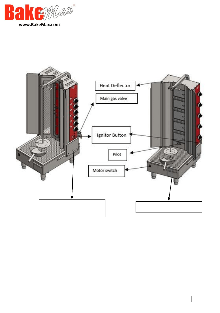
Part Identification
Grease / Oil Drip Container
Knob to Adjust Distance
Between Burner & Meat

12
OPERATION
It is recommended to light the upper most burner first, then work your way to the lower
burners when first firing up the unit.
• This machine can work with LPG & NG. It ships setup for NG, therefor if you are
using LP, please make sure you have the correct orifices installed & the piece inside
the cap of the gas appliance regulator has been switched for LP.
• Plug in the Machine to power the motor that rotates the meat.
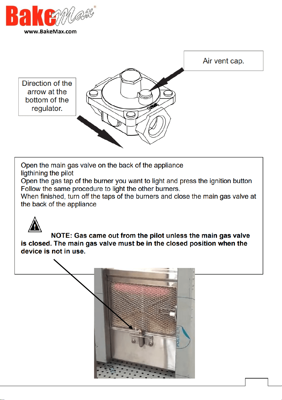
• Open the manual gas valve on the back of the unit to release the gas to the unit.
• Light the Standing Pilot at the center bottom of the burners with a manual bbq
lighter. Note: This pilot must be always lit, or gas will escape through the pilot.
• The base of the spit is adjustable, adjust the base to height that you desire & place
your meat onto the spit.
• On the control panel, there are images next to each knob, corresponding to a
diagram of the burners on the unit.
• Turn the top knob to your desired position & press the red ignitor button at the
bottom of the control panel. Repeat this process with the 2
nd
knob down & work
your way down until all the burners you wish to light are lit. You must light the top
burner first and work your way down by turning on one knob at a time.
• You can turn on the motor that rotates the meat by using the switch on the front
left part of the machine. When the switch is in the (1) position, the skewer rotates
clockwise, and in the (2) position it rotates counterclockwise.
• You can adjust the appropriate distance between the skewer and the burner by
pulling out the metal knob on the lower right side of the unit and sliding the frame
forwards or backwards.
• You can cut the cooked meat with the help of the doner knife and catch it with the
included meat shovel. You can also save it in the meat collection tray at the bottom.
• After the cooking process is finished, turn off the gas knobs on the side of the stove
one by one.
• To turn off the electric motor that rotates the skewer, turn the switch to the middle
(OFF) position.
NOTE: Gas will come out from the pilot unless the main gas valve is closed. The main
gas valve must be in the closed position when the device is not in use.
13
GAS CONVERSION INSTRUCTIONS
Natural Gas – 4” WC – (QTY 4) * Ø 1.4 mm (0.055") Orifices
Liquid Propane – 10” WC – (QTY 4) * Ø 0.9 mm (0.035”) Orifices
Replacement of Burner Orifices:
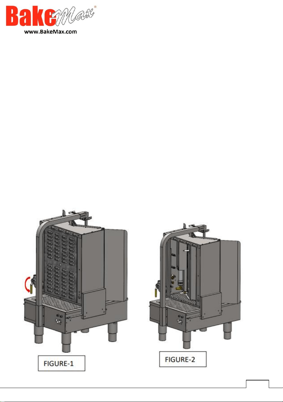
1. Close the gas valve of the product, (Figure-1)
2. Remove the back cover (figure-2)
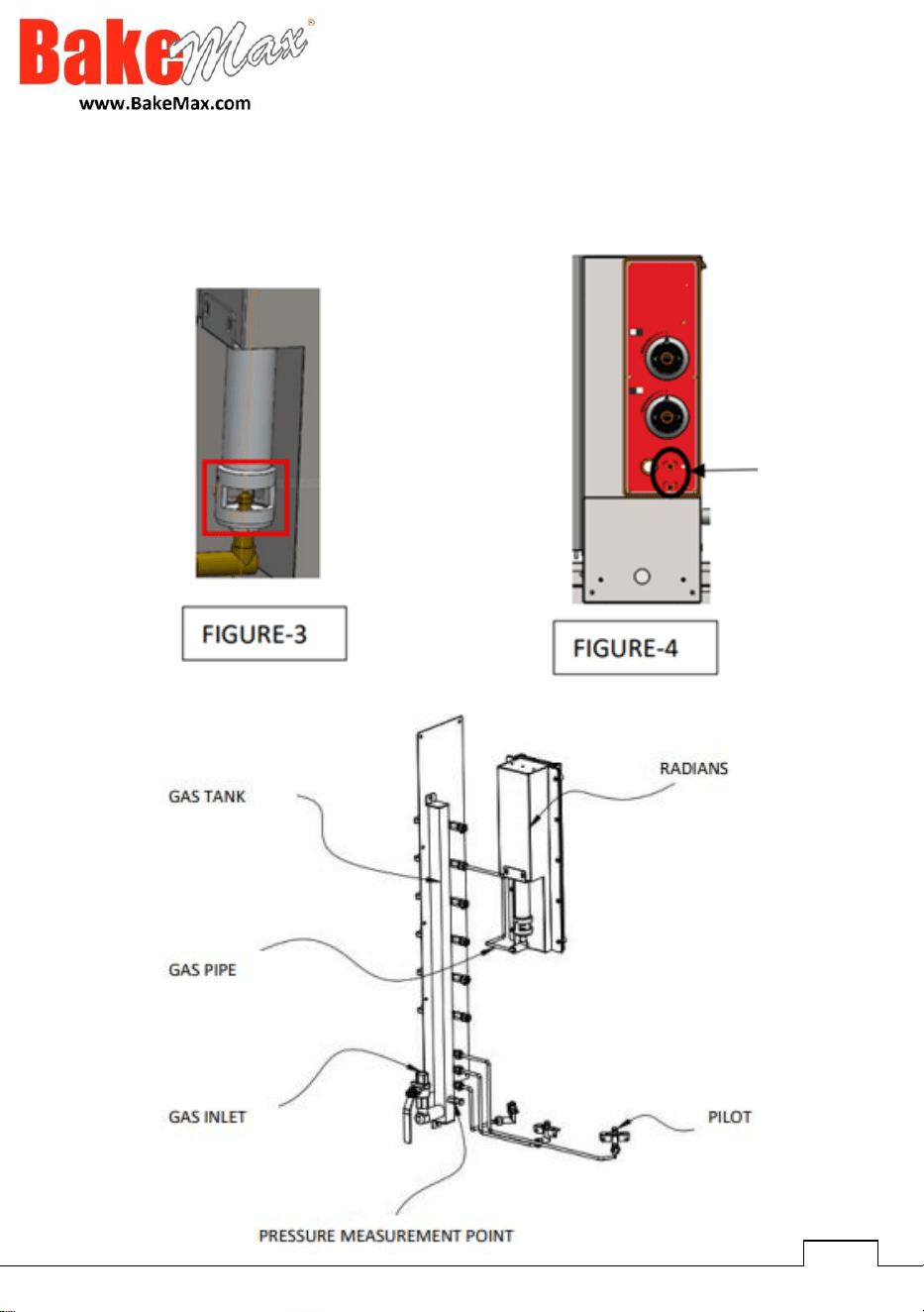
3. The product is factory set for NG gas. Replace with LPG injectors in
accordance with the values specified in the table above. (Figure-3)
4. After the injector replacement, open the gas valve and light the pilots with
an auxiliary lighter.
5. The flame length of the pilot may be low or high due to gas change. Adjust
the pilot flame length by using a suitable screwdriver to adjust the gas valves
in the holes at the bottom of the burner buttons. (Figure-4)
14
GAS CONVERSION INSTRUCTIONS
15
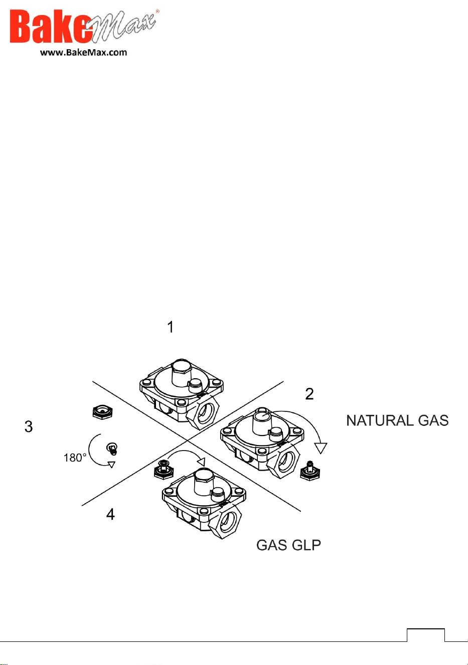
GAS CONVERSION INSTRUCTION
Converting the Gas Appliance Regulator:
After converting the equipment gas, the pressure regulator must be
converted by inverting the fitting under the regulator cover. This will require a
reasonable amount of force. Do not remove the spring.
When replacing the cover, make sure the insert of the socket is facing
upwards in the middle of the spring. As shown in the image on the following
page. Then re-attach the pressure regulator to the gas inlet of the equipment
and apply the "Warning" sticker for the gas to be used on the front of the unit
for future reference.
16
CLEANING & MAINTENANCE
➢ CLEANING AND MAINTENANCE AFTER EVERY USE
1. Make sure to clean the body, bottom plate, skewers and radians of the
appliance after each cooking process.
2. While cleaning the device, make sure that the plug is not in the socket or
the switch is turned off. Disconnect the gas connection.
3. Do not use acid and derivative materials for cleaning the device.
4. While cleaning the device, do not wash the device with water. Otherwise,
water will get into the electric motor and cause it to burn.
5. Remove the meat and burnt fat residues accumulating on the bottom of
the turntable by first soaking them in hot water and then scraping them
with a spatula.
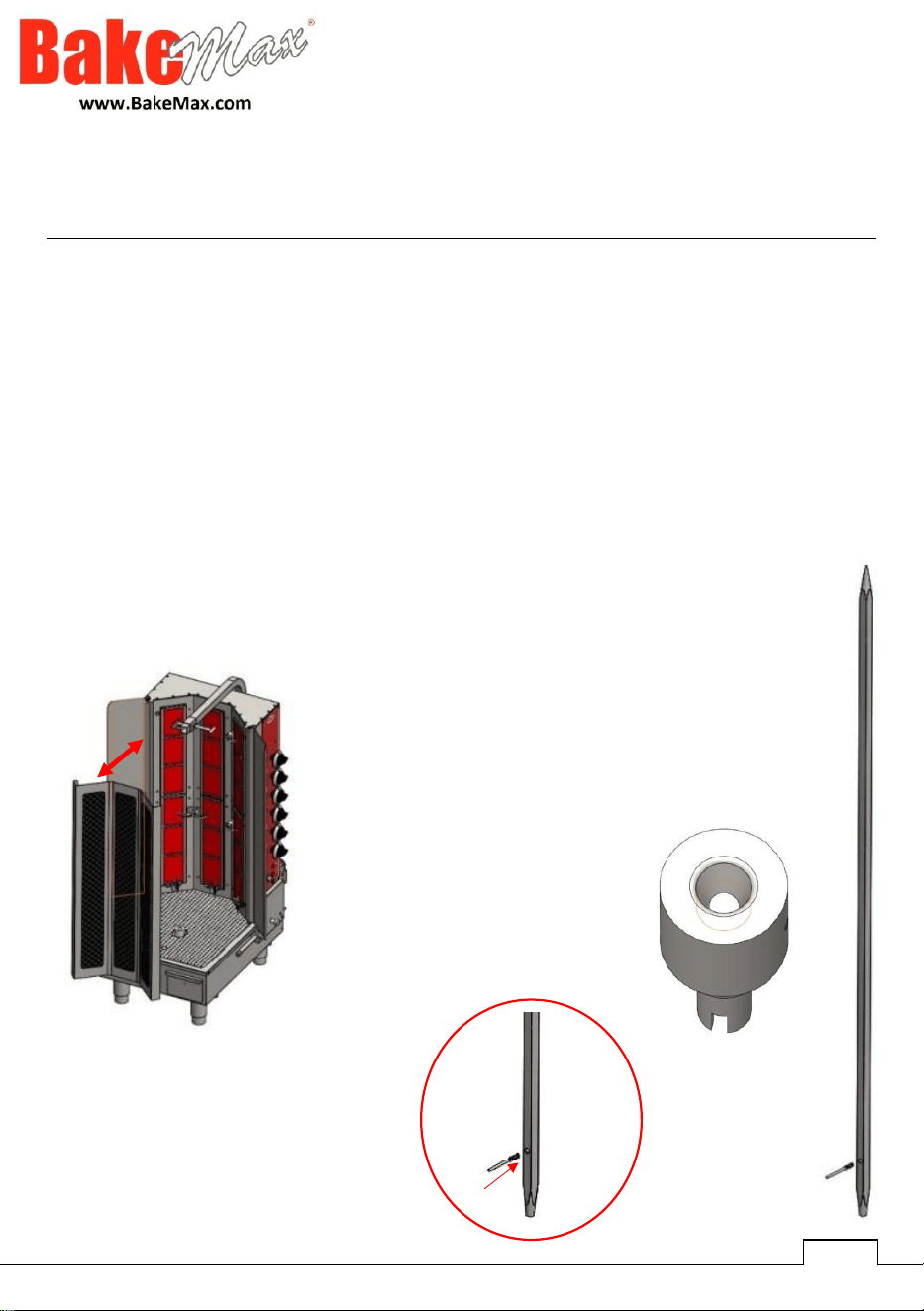
To clean the grill, remove the grill by
sliding it upwards after it has cooled
down. Clean with a damp cloth. After
cleaning, it is assembled again as
disassembled.
This part can be
cleaned with a
damp cloth.
During the daily cleaning of the
doner cooker, the hole in the meat
skewer is removed with the
machine. Clean with a wire brush.
17
CLEANING & MAINTENANCE
➢ CLEANING AND MAINTENANCE PERIODICALLY
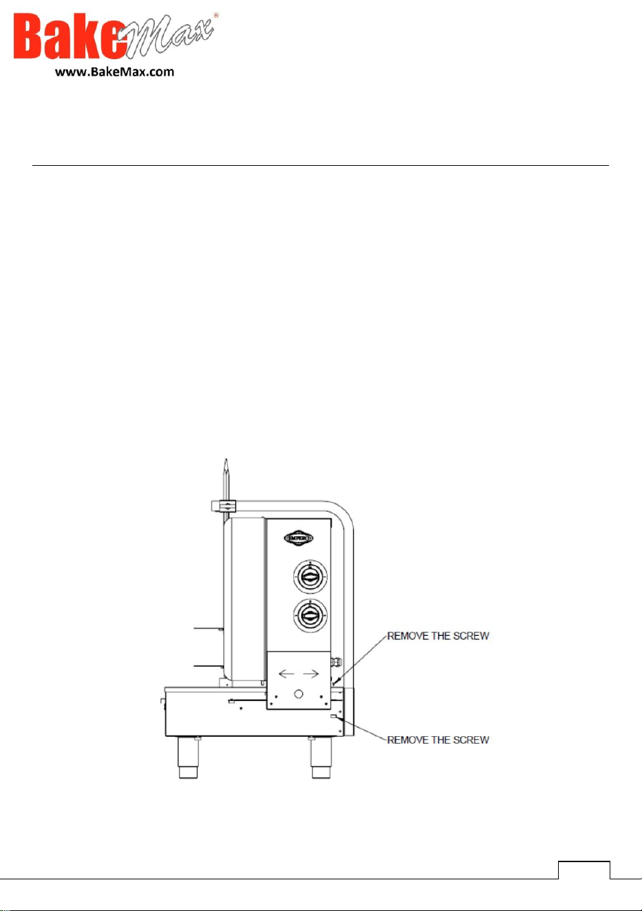
• Maintenance should only be carried out by trained people.
• Perform periodic maintenance of the device every 15 days.
• Shawarma machines require minimal maintenance (motor and bearings are
lubricated).
• Check the gas connection hoses at regular intervals.
• In bottom motor shawarma machines, maintain the moving slides.
• Check the ventilation of the environment where the device is located at
regular intervals.
• According to the frequency of use, the contactor maintenance of the device
should be done by blowing dry air after the electrical connection is
disconnected.
18
CLEANING & MAINTENANCE
➢ CLEANING AND MAINTENANCE – CLEANING THE SLIDES
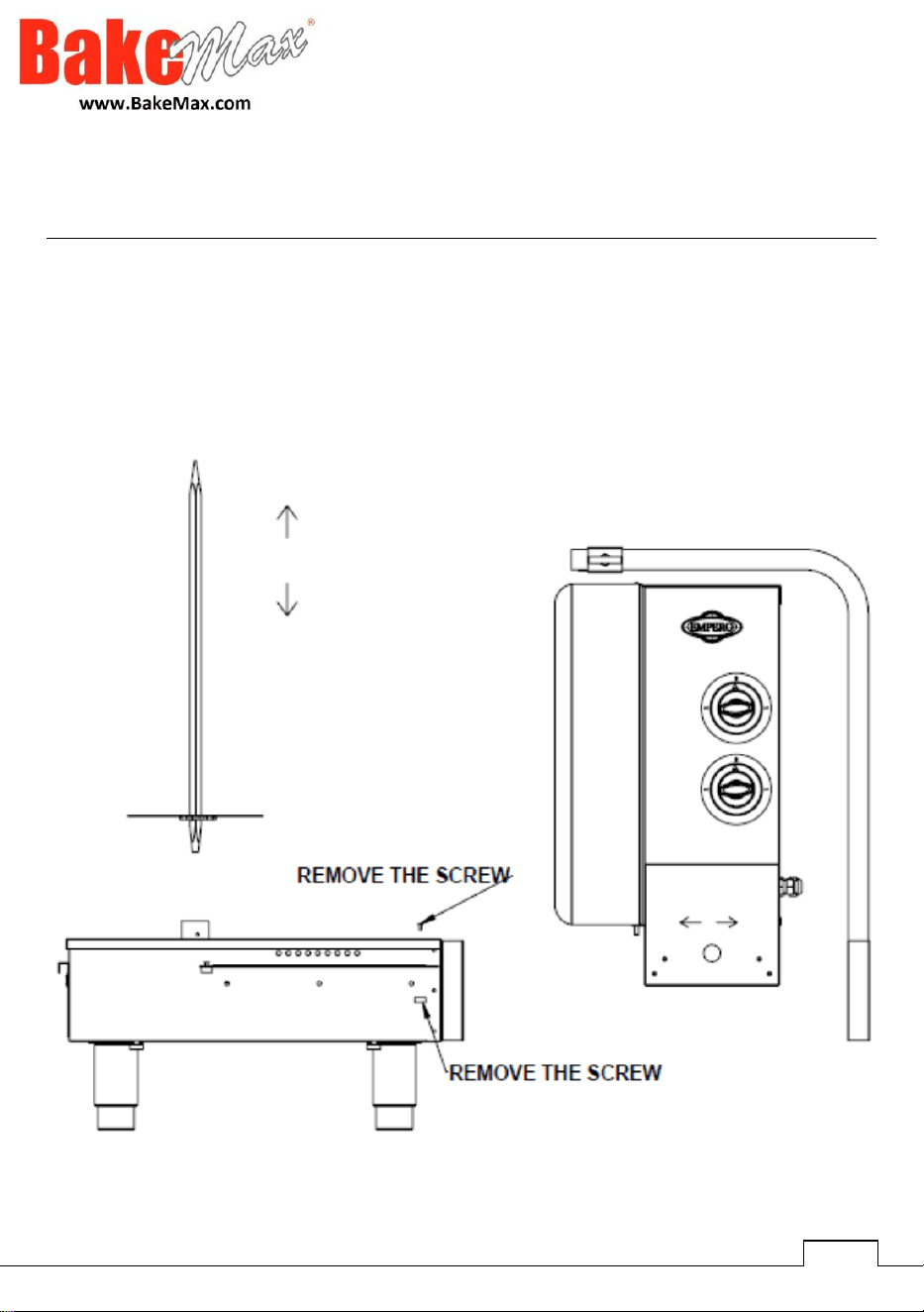
• Remove the screws as indicated by the arrows in Picture 1.
• Push the Doner Stove so that its radiant go backwards
• As seen in picture 2, the furnace part will be separated
• You can now easily clean the sleds and ports
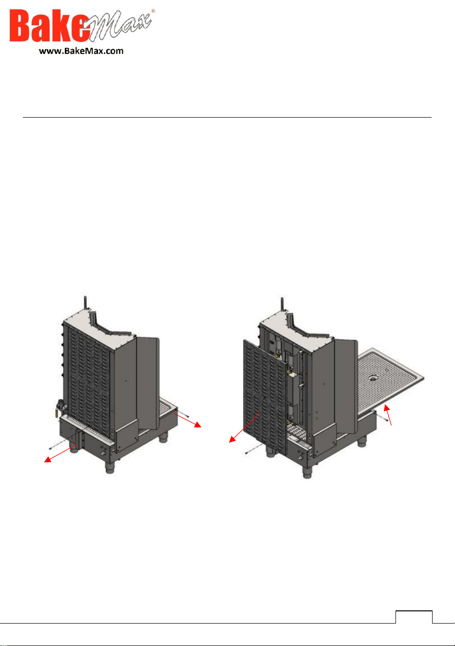
19
CLEANING & MAINTENANCE
➢ CLEANING AND MAINTENANCE – CLEANING THE PAN
Product Cleaning should only be done by authorized service as shown in the picture
below.
• Remove the screws connected to the pan and louver
• After the screws are removed, the pan and louvered sheet can be removed
• Once the pan and louver are removed, clean as necessary and re-assemble
after cleaning

20
TROUBLESHOOTING
THE APPLIANCE DOESN’T
OPERATE
1. Check whether the plug of the device is
plugged into the socket.
2. Check the electrical connections.
3. Check whether the gas connection of
the device is made.
4. Check if gas is coming from the burners
THE APPLIANCE DOESN’T COOK WELL
1. Check the distance between the
skewer and the burner
2. Do not put more meat on the
skewer then its capacity
THE APPLIANCE STOPPED
1. The device may stop due to low
voltage, in this case, check the
voltage
2. In case the flame emanating from
the radians of the shawarma
machine goes out unintentionally,
the gas output will be cut off
automatically because there is a
safety valve, in this case, the device
will not work
21
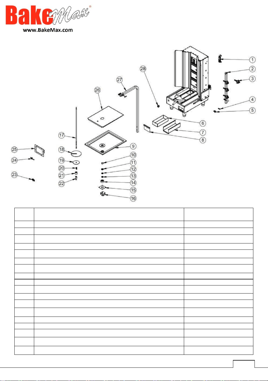
#
Part Description
Factory Code
1
6-OUTLET IGNITION COIL 110-240VAC
M.ELK-CKM-001
2
EMP.DN.151-USA GAS STORAGE
M.GAZ-DPO-DN-015
3
EMP BUTTON ARROW BLACK PRINTED
M.AKS-DGM-EMP-024
4
EMP.DN.150-3R-UL-PRESSURE MEASURING PART
YTL-KNX.DNR-KS-0062
5
SPARK PLUG IGNITION BUTTON
M.ELK-SLT-BTN-002
6
OIL PANS
YSC-KNX.DNR-PN-0087
7
OIL SLED HAIR
YSC-KNX.DNR-PN-0093
8
OIL PAN FRONT SHEET
YSC-KNX.DNR-PN-0088
9
PRESS PRINT PANS 49x66
M.MTS-KNX-DNR-001
10
32x1.5 PIPED PIPE MEAT PAN RING
YBR-KNX.DNR-KS-0005
11
25x37x7 BEARING (6805 ZZ)
M.RLM-ISI-004
12
17x31x8 BEARING (51103)
M.RLM-ISI-005
13
17x30x9 BEARING (6903)
M.RLM-ISI-003
14
EMP.KLG.015 (F1) BEARING HOUSING-3,4 CM
YTL-KNX.DNR-KS-0031
15
BEARING HOUSING CONNECTION SHEET
YSC-KNX.DNR-PN-0099
16
BEARING HOUSING CONNECTION SHEET
YSC-KNX.DNR-PN-0099
17
EMP.DN.151-USA ROTARY SKEWER
YTL-KNX.DNR-KS-0078
18
EMP.DN.150-3R-UL DIAMETER 200MM MEAT MIRROR SC
YSC-KNX.DNR-LZ-0213
BMDN151USA4
Parts Breakdown & List
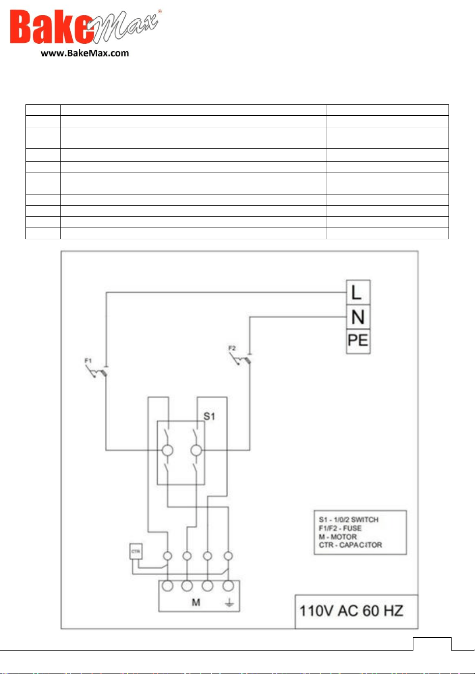
22
19
EMP.DN.150-3R-UL DIAMETER 125MM ET MIRROR SC
YSC-KNX.DNR-LZ-0214
20
INOX SPRING COPIA
B-KPL-SYH-5x97-4,0x78
21
EMP.DN.150-3R-UL SHANK TURNING DEVICE GROUP
(FEMALE) 40 MM
YTL-KNX.DNR-KS-0059
22
SHANK TURNING APPARATUS GROUP (MALE) 80 MM
YTL-KNX.DNR-KS-0018
23
DN.152-USA PILOT MON
YTL-KNX.DNR-KS-0056
24
IGNITION SPARK PLUG
M.GAZ-CKM-BUJI-007-4-6-
9G
25
STONY RADIANT-WIRE 310K GNŞ EMPERO
M.GAZ-BRL-RDY-001
26
EMP.DN.150-3R-UL STRAINER
YSC-KNX.DNR-PN-0158
27
4 L DNR REAR L PROFILE 30x30x1,2 1530
YPR-KNX.DNR-KS-0019
28
T105 16A 1-3 HP 125-250 VAC 0-1-2 BLACK KEY LARGE
M.ELK-SLT-AN-003

23
Warranty & Service
BakeMax provides a 1-Year Limited Parts and Labor warranty on most items, there are select
items which carry a Limited 2-Year Warranty. Extended Warranty is available on some
products. Please contact us for details. The Warranty is not transferable and is limited to
original installation of equipment sold by BakeMax for the original user.
For all Warranty Claims, Proof of Purchase and/or Serial Number is required. Once the
machine is approved, BakeMax will provide our customers with on-site Warranty Coverage on
all equipment more than 100lbs. BakeMax assumes no responsibility for down time or loss of
product. Repairs must be Pre-Authorized by BakeMax and have a Service Authorization
Number issued prior to commencing Warranty Service.
Warranty begins 10-Days after shipping from warehouse; delays in installation which would
extend the Warranty must be Approved. All equipment must be installed and connected by
Qualified Professionals in accordance with the Manual Specification. Products shipped are to
be inspected at time of delivery, the receiver is responsible for inspection.
Any abuse or improper use of the equipment will void the warranty. This includes failure to
follow all cleaning instructions, improper installation, improper maintenance, failure to follow
capacity charts, improperly wired electrical connections. The Warranty does not apply to
abuse, willful or accidental damage, or to products used for other than their intended purpose.
Normal wear parts such as Accessories, Attachments, or Electrical Components such as
Fuses, Bulbs, Elements, and Switches carry a 90-Day Warranty only.
Bench Warranty (Machines Weighing 100 lb. or less)
Once the machine is Approved for Warranty Service, if the machine requires Warranty work
in less than 30 days of purchase date, BakeMax will pay all shipping charges. Once the
machine is received and repaired it will be returned to the user at BakeMax expense. Freight
Damages during return shipping is the responsibility of the owner of the machine.
The following is not covered under the BakeMax Warranty:
1. Overtime Labor Rates are not covered by BakeMax.
2. All parts will be shipped via Ground Courier only; If Express Shipping is required, it will be
the responsibility of the Customer or Dealer.
3. Travel for Warranty Service is covered up to 100 Miles /160 Km Roundtrip, any further
milage will be the responsibility of the Customer or Dealer.
4. There is no on-site Warranty Service for Residential Addresses or addresses outside of the
contiguous United States (Lower 48) or Canada.
**BakeMax machines sold outside of the contiguous United States (Lower 48), or Canada will carry 1-
Year Parts Warranty only.