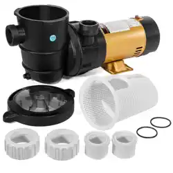
ABOVE GROUND PUMP POOL 1.5HP 2 SPEED
SAVE THIS MANUAL: KEEP THIS MANUAL FOR SAFETY WARNINGS, PRECAUTIONS, ASSEMBLY,
OPERATING, INSPECTION, MAINTENANCE AND CLEANING PROCEDURES. WRITE THE PRODUCT’S
SERIAL NUMBER ON THE BACK OF THE MANUAL NEAR THE ASSEMBLY DIAGRAM (OR MONTH
AND YEAR OF PURCHASE IF PRODUCT HAS NO NUMBER).
OWNER’S MANUAL AND SAFETY INSTRUCTIONS
ITEM: 75113
FOR QUESTIONS PLEASE CALL OUR CUSTOMER SUPPORT: (909) 628 0880 MON-FRI 9AM TO 3PM PST

GENERAL SAFETY WARNINGS
Read all safety warnings and instructions. Failure to follow the warnings and instructions may result
in electric shock, re and/or serious injury. Save all warnings and instructions for future reference.
The warnings, precautions, and instructions discussed in this instruction manual cannot cover all possible
conditions and situations that may occur. It must be understood by the operator that common sense and
caution are factors which cannot be built into this product, but must be supplied by the operator. Read
carefully and understand all ASSEMBLY AND OPERATION INSTRUCTIONS before operating. Failure to
follow the safety rules and other basic safety precautions may result in serious personal injury.
1
WARNING: (For cord & plug connected units). Risk of Electrical Shock. Connect only to a grounding
type receptacle protected by a ground-fault circuit-interrupter (GFCI). Contact a qualied electrician if
you cannot
WARNING: (For cord & plug connected units). Do not bury cord. Locate cord to minimize abuse from
lawnmowers, hedge trimmers and other equipment.
WARNING: (For cord & plug connected units). To reduce the risk of electric shock, replace damaged
cord immediately.
WARNING: (For cord & plug connected units). To reduce the risk of electrical shock do not use an
extension cord to connect unit to electrical supply; provide a properly located outlet.
CAUTION:
(For pumps with a 25 ft. (7.62m cord). This pump is for use with storable pools only. Do not
use with permanently installed pools. A storable pool is constructed so that it may be readily disassembled
for storage and reassembled to its original integrity. A permanently installed pool is constructed in or on
the ground or in a building such that it cannot be readily disassembled for storage.
CAUTION: (For pumps with/without 3ft.(91m cord) or 6ft.(1.82m cord). This pump is for use with
permanently installed pools and may also be used with hot tubs and spas if so marked. Do not use with
storable pools. A permanently installed pool is constructed in or on the ground or in a building such that it
cannot be readily disassembled for storage. A storable pool is constructed so that it may be readily
disassembled for storage and reassembled to its original integrity.
Though this product is designed for outdoor use, it is strongly advised to protect the electrical components
from the weather. Select a well-drained area, one that will not ood when it rains. It requires free circulation
of air for cooling. DO NOT install in a damp or non-ventilated location.
WARNING: (For hot tub and spa pumps). Do not install within an outer enclosure or beneath the skirt
of the
Hazardous voltage can shock, burn, or cause death. To reduce the risk of electric shock, DO NOT use
an extension cord to connect unit to electric supply. Provide a properly located outlet. It is required that
licensed electricians do all electrical wiring. All electrical wiring MUST be in conformance with applicable
local and national codes and regulations. Before working on pump or motor, disconnect motor wiring.
To reduce the risk of electric shock replace damaged cord immediately. DO NOT bury cord. Locate cord
to prevent abuse from lawn mowers, hedge trimmers and other equipment.
IMPORTANT SAFETY INFORMATION

2
INSTALLATION
INSTALLATION LOCATION
Locate pump as close to pool/spa as possible, preferably in a dry, well ventilated area away from direct
sunlight. It should be on a hard, level surface. Give consideration to:
1. Drainage – away from pump.
2. Ventilation of pump motor.
3. Access for future servicing and winterizing.
4. Protection from the elements.
Pumps without strainer bodies are designed for flooded suction (all suction fittings and suction piping below
water level) and will not self-prime. Consequently, the pump must be installed at an elevation that is below
water level when pool or spa is filled; however, if suction line valves are installed, the pump may be closed
for priming. Keep vertical distance to a minimum if you choose to mount pump above water level.
Pumps with strainer bodies are self-priming but should be mounted as close to the water level as possible or
below for ease in priming.
GENERAL PLUMBING
FOR SOLVENT WELD CONNECTION
Rigid or
exible PVC pipe can be used. Pipe ends should be clean and free of any ash cause by the cutting
operation. Be sure that the proper adhesive is used on the type of pipe specied.
Note: A primer will assure that adhesive joints are superior. Suregard P-3000 has a purple tracer to qualify
in areas where codes specify a primer must be used.
CAUTION: We recommend that you consider climatic conditions when applying adhesives. Certain
atmospheric situations, such as high moisture content, make adhesive action of certain glues less effective.
Check the manufacturer’s instructions.
FOR THREADED CONNECTIONS
Use only Teon tape or equivalent on threaded plumbing connections. Other pipe compounds may damage
threads. We do not recommend the use of silicone or petroleum based compounds. DO NOT OVERTIGHTEN
– HAND TIGHTEN PLUS ½ TURN IS SUFFICIENT.
PUMP PLUMBING
Suction pipe should be as large or larger that discharge pipe. Avoid using suction pipe small that pump
connection. Keep the piping as straight and short as possible, and of suitable size. Avoid connecting an
elbow directly into the pump inlet (use a length of straight pipe to allow a proper entry for the water). Arrange
horizontal runs to slope upward to the pump to prevent high spots that could form air pockets. Support the
pipe independently so that it places no strain on the pump. Keep as much of the suction line as possible
below the water level to reduce priming time. Install valves and unions in the pump suction and return lines
to facilitate servicing. Valves are recommended for throttling maintenance if the system is installed below
deck level. Suction valves are essential for priming all pumps without strainer bodies installed above water
level. Pumps with strainer bodies are self-priming, nevertheless, we recommend the use of check valve in
the suction pipe at or below the water level if the suction lift is more that ve feet or if the dry suction is more
that ten feet long. Keep the valve in the suction line fully open during operation.
ELECTRICAL DATA
Refer to information on motor nameplate fo electrical service data. All motors should have fused disconnect
switch or circuit breaker. Be sure wire size is sufcient f or p ump HP a nd d istance f rom power source.
Wiring should be done in accordance with applicable codes by a competent electrician. We recommend the
installation of a ground fault circuit interrupter for maximum safety.
3
OPERATION
PUMP START UP
Do not operate pump until it has been primed as water acts to cool and lubricate the seal. For pumps without
strainer bodies and locater above water, close suction line valve and ll pump with water in order to prime.
For pumps with strainer bodies and located above water, prime by removing strainer cover and lling strainer
body with water. Pumps located below water level will selfprime if all piping is also below water level. After
pump has been primed, energize motor and open all suction and discharge line valves. It may take some time
for pump to remove air from suction lines. If no ow is observed in ve minutes, stop the motor and re-prime.
If the pump fails to operate, check for air leaks. Refer to Trouble Shooting section.
After about ten minutes of operation, check the return ttings for air bubbles. A continuous ow of air indicates
leaks in suction line. Locate and correct any leaks immediately.
CONTROLLING THE OUTPUT
Keep the gate valve in the suction line fully open during operation. Should it be necessary to control the
output, use a valve in the return line.
Caution: Do not retighten strainer Ring-Lok during operation.
Caution: Do not operate pump with closed suction or discharge valves.
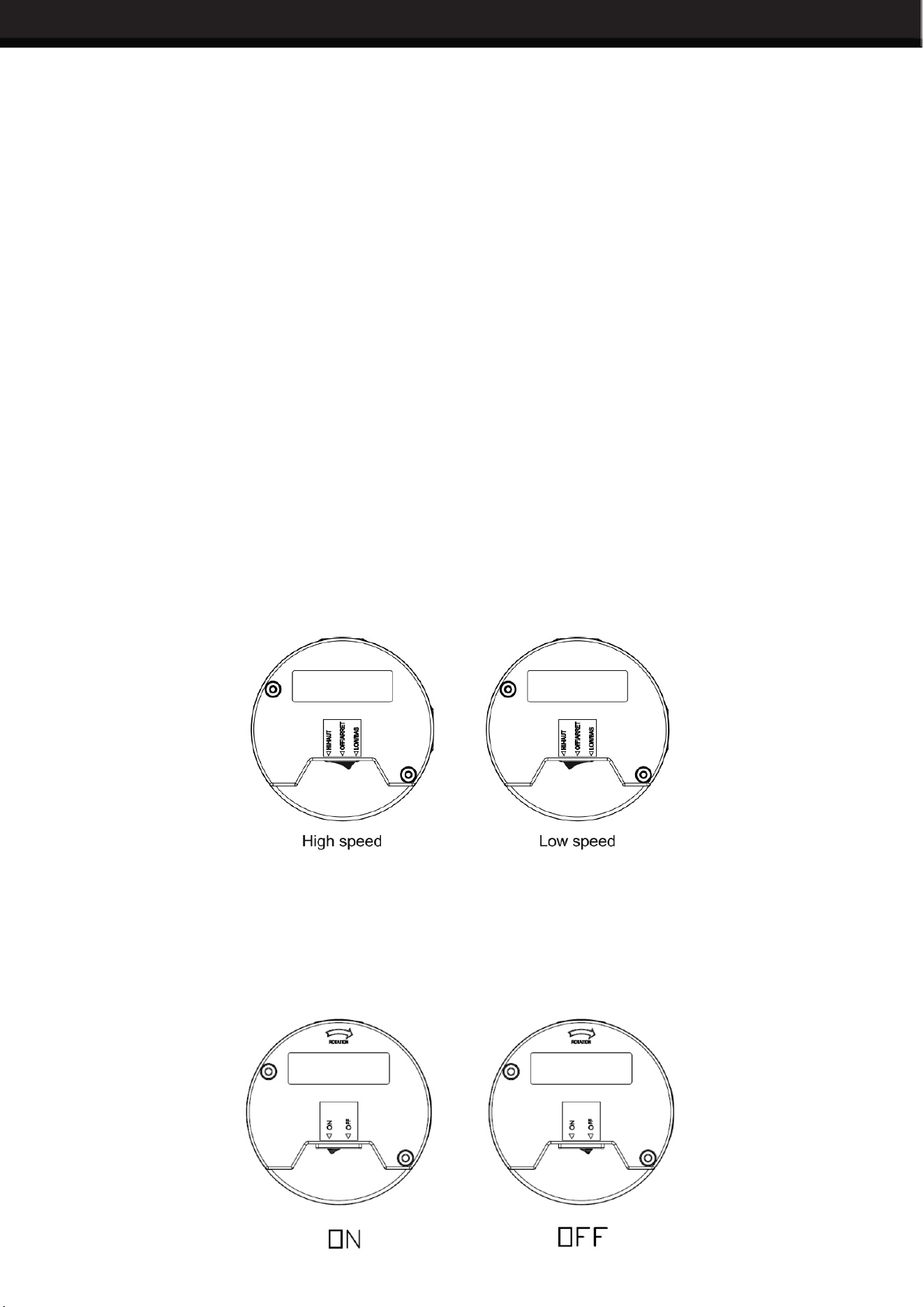
TWO-SPEED PUMPS
Two-speed models are recommended in a swimming pool when high speed is needed for maximum ltration
at peak periods and whenever turbidity levels are high. At other times, switch to low speed. For backwashing
and vacuuming, high speed is required. In spas and hot tubs, use high speed to attain full performance in
the hydro-therapy mode. At other times, such as lter/heat cycle mode, use low speed. Low speed provides
sufcient ow to activate most spa heaters and provides sufcient ow for ltration. In jetted tubs, use high
speed to attain full performance in the hydro-therapy mode and use low speed mode to prime. The below
picture shows how to switch between the high speed and low speed.
ON-OFF SINGLE-SPEED PUMPS
In order to have a safer and quicker start of the swimming pool filtration systems (or pumps), it is very
necessary to install ON-OFF switch. Without it, every start or shut down need to plug/unplug the power
cord, it will cause a lot
of safety risks, such as, spark occurs when plug/unplug the power cord and frequent
plug/unplug will cause po or contact between plug and socket. The below picture shows how to switch
between ON and OFF.

4
MAINTENANCE
WINTERIZING
Consult your dealer for advice on winterizing your equipment if freezing temperatures occur in your locality.
His knowledge of your equipment makes him/her the best qualied source of information. Follow their
recommendations, and if these include draining the lter system, proceed as follows:
1. If your system does not contain a lter, proceed to step2.
A. For sand lters: BACKWASH for 3 to 5 minutes and set dial valve to WINTERIZE.
B. For cartridge lters: Clean the lter element and store in a dry place.
2.
Drain system by loosening drain plugs (drain plugs will drain without completely removing the plug from
unit) and/or removing pipe caps.
WATER CHEMISTRY
A proper and consistent use of chemicals is necessary to maintain clean, sanitary water, prevent a spread of
germ infection and control the growth of algae which can spoil the appearance and enjoyment of your pool
or spa. Chlorine is the most commonly used chemical to provide clean, sanitary water. Either dry or liquid
chlorine (calcium or sodium hypochlorite) can be used which should be added daily as it is dissipated by dirt
and germs as well as be the sun and wind. It is also important that the correct level of acidity or alkalinity of
the pool water be maintained. This is the pH of your pool with pH 7.0 being neutral. Readings above 7.0 are
alkaline and below are acid. A desirable range is 7.2 – 7.4.
PUMP MAINTENANCE
1. Motors are self-lubricating – no lubrication required.
2. Clean hair & lint strainer if you have a strainer body pump.
3. Visually inspect motor for blockage of air vents on motor shell. Remove any debris after breaker off.
4. Shaft seals may become worn and must be replaced if leakage is observed.
SERVICE & REPAIR PARTS
Refer all service to your local dealer as his knowledge of your equipment makes him the best qualied source
of information. Order all repair parts through your dealer. Give the following information when ordering repair
parts:
1. Unit nameplate data.
2. Description of part.
CLEANING
Switch power off. Close valves in suction and return line. Unscrew strainer Ring-Lok counterclockwise and
remove the strainer cover from hair and lint strainer and lift out strainer basket. Clean and replace the basket.
Take care to seat basket properly. Clean O-Ring and re-lubricate with petroleum jelly if necessary. Clean
O-Ring seats on cover and strainer. Ret cover and strainer – hand tighten only – and open valves. Put pump
back into operation. Caution: Do not retighten strainer during operation.

5
•
Power: 1.5HP
• Voltage: 115/60Hz
• Speed: 2
• Amp: 12/3.6
• Low-Speed: 1750r/min
• Hi-Speed: 3450r/min
• Max Flow: 4980 GPH
• Fitting Size: 1.5NPT
• Max Section Height: 40ft
• Certication: UL
• Hardware Required: Yes
• Overall Dimension: 22”(L) x 7-1/2”(W) x 10-1/2”(H)
TROUBLESHOOTING
MOTOR DOES NOT START
1. Disconnect switch or circuit breaker in OFF
position.
2. Fuses blown or thermal overload open. Locked
motor shaft.
3. Motor windings burned out.
4. Defective starting switch inside single-phase
motor 5. Disconnected or defective wiring
6. Low voltage
MOTOR DOES NOT REACH FULL SPEED
1. Low voltage
2. 2 speed model set on low speed
3. Motor windings connected for wrong voltage on
dual voltage model.
PUMP DELIVERS NO WATER
1. Pump is not primed
2. Closed valve in suction or discharge line
3. Leakage or air into suction system
4. Impeller clogged
LOW PUMP CAPACITY
1. Valve in suction or discharge line partly closed
2. Suction or discharge line partly plugged
3. Suction or discharge line too small
4. Pump running at reduced speed (see above)
5. Plugged basket in skimmer or hair and lint
strainer
6. Dirty lter
7. Impeller clogged
8.
Wrong rotation (3 phase only)
LOW PUMP PRESSURE
1. Pump running at reduced speed (see above)
2. Wrong rotation (3 phase only)
3.
Discharge valve or inlet ttings closed too much
HIGH PUMP PRESSURE
1. Discharge valve or inlet ttings closed too much
2.
Return lines too small
3. Dirty lters
NOISY PUMP AND MOTOR
1. Plugged basket in skimmer or hair in lint strainer
2. Worn motor bearings
3. Valve in suction line partly closed
4. Suction line partly plugged
5. Vacuum hose plugged or too small
6. Pump not supported properly
LEAKAGE OF WATER AT SHAFT
1. Shaft seal requires replacement
AIR BUBBLES AT INLEY FITTINGS
1. Leakage air into suction line at connections or
valve stem
2. Cover gasket of hair and lint strainer needs
cleaning
3. Restriction in suction line
4. Low water level in pool
NOTE: If the recommendations in the Trouble
Shooting portion of this manual do not solve your
particular problem(s), please contact your local
dealer for service.
TECHNICAL SPECS
6
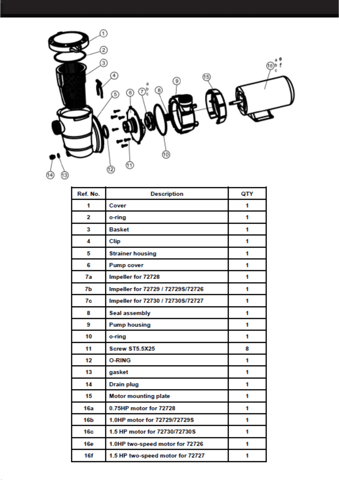
PARTS LIST
7
THE MANUFACTURER AND/OR DISTRIBUTOR HAS PROVIDED THE PARTS LIST AND ASSEMBLY
DIAGRAM IN THIS MANUAL AS A REFERENCE TOOL ONLY. NEITHER THE MANUFACTURER OR
DISTRIBUTOR MAKES ANY REPRESENTATION OR WARRANTY OF ANY KIND TO THE BUYER THAT
HE OR SHE IS QUALIFIED TO MAKE ANY REPAIRS TO THE PRODUCT, OR THAT HE OR SHE IS
QUALIFIED TO REPLACE ANY PARTS OF THE PRODUCT. IN FACT, THE MANUFACTURER AND/OR
DISTRIBUTOR EXPRESSLY STATES THAT ALL REPAIRS AND PARTS REPLACEMENTS SHOULD BE
UNDERTAKEN BY CERTIFIED AND LICENSED TECHNICIANS, AND NOT BY THE BUYER. THE BUYER
ASSUMES ALL RISK AND LIABILITY ARISING OUT OF HIS OR HER REPAIRS TO THE ORIGINAL
PRODUCT OR REPLACEMENT PARTS THERETO, OR ARISING OUT OF HIS OR HER INSTALLATION
OF REPLACEMENT PARTS THERETO.
Record Product’s Serial Number Here:
Note: If product has no serial number, record month and year of purchase instead.
Note: Some parts are listed and shown for illustration purposes only and are not available individually
as replacement parts.
PLEASE READ THE FOLLOWING CAREFULLY
DISCLAIMER
PRODUCT MADE IN CHINA
