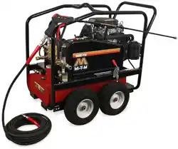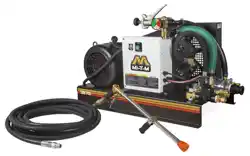

Operator's Manual 1
©Copyright 2006 Form #37-0965-E/S-040423
OPERATOR'S MANUAL FOR
CHV SERIES
COLD WATER BELT DRIVEN
PRESSURE WASHER
CAUTION
RISK OF INJURY!
READ MANUAL BEFORE OPERATING!
This manual is an important part of the
pressure washer and must remain with this unit!
2 Operator's Manual
WARNING: This product can expose you to
chemicals including Lead, which is known to
the State of California to cause cancer and birth
defects or other reproductive harm. For more
information go to www.P65Warnings.ca.gov
WARNING
TABLE OF CONTENTS
INTRODUCTION ...........................................................................................................................3
IMPORTANT SAFETY INSTRUCTIONS ..................................................................................... 4
FEATURES FOR CHV-0525-0ME1/0ME3 .................................................................................... 6
FEATURES LISTING ....................................................................................................................6
FEATURES FOR CHV-0525-1ME1/1ME3 .................................................................................... 7
FEATURES LISTING ....................................................................................................................7
SAFETY DECALS & PLACEMENT .............................................................................................8
INSTALLATION & PREPARATION ..............................................................................................9
OPERATING INSTRUCTIONS ...................................................................................................13
STORAGE & MAINTENANCE ...................................................................................................15
TROUBLESHOOTING ................................................................................................................17
STATEMENT OF WARRANTY ................................................................................................... 18
Operator's Manual 3
INTRODUCTION
Congratulations on the purchase of your new new Cold Water Pressure Washer! You can be assured your pressure
washer was constructed and designed with quality and performance in mind. Each component has been rigorously
tested to ensure the highest level of acceptance.
This operator's manual was compiled for your benet. By reading and following the simple safety, installation, operation,
maintenance and troubleshooting steps described in this manual, you will receive years of trouble free operation from
your new pressure washer. The contents of this manual are based on the latest product information available at the time
of publication. The manufacturer reserves the right to make changes in price, color, materials, equipment, specications
or models at any time without notice.
! IMPORTANT !
These paragraphs are surrounded by a "SAFETY ALERT BOX". This box is used to designate and emphasize
Safety Warnings that must be followed when operating this pressure washer.
Accompanying the Safety Warnings are "signal words" which designate the degree or level of hazard serious-
ness. The "signal words" used in this manual are as follows:
DANGER: INDICATES AN IMMINENTLY HAZARDOUS SITUATION WHICH, IF NOT AVOIDED, WILL
RESULT IN DEATH OR SERIOUS INJURY.
WARNING: INDICATES A POTENTIALLY HAZARDOUS SITUATION WHICH, IF NOT AVOIDED, COULD
RESULT IN DEATH OR SERIOUS INJURY.
CAUTION: INDICATES A POTENTIALLY HAZARDOUS SITUATION WHICH, IF NOT AVOIDED MAY RESULT
IN MINOR OR MODERATE INJURY.
The symbols set to the left of this paragraph are "Safety Alert Symbols". These symbols are used to call atten-
tion to items or procedures that could be dangerous to you or other persons using this equipment.
ALWAYS PROVIDE A COPY OF THIS MANUAL TO ANYONE USING THIS EQUIPMENT. READ ALL INSTRUC-
TIONS BEFORE OPERATING THIS PRESSURE WASHER AND ESPECIALLY POINT OUT THE "SAFETY WARN-
INGS" TO PREVENT THE POSSIBILITY OF PERSONAL INJURY TO THE OPERATOR.
Once the unit has been uncrated, immediately write in the serial number of your unit in the space provided below.
SERIAL NUMBER_________________________________
Inspect for signs of obvious or concealed freight damage. If damage does exist, le a claim with the transportation
company immediately. Be sure that all damaged parts are replaced and that the problems are corrected prior to
operation of the unit. If you require service, contact Customer Service at our toll-free number:
800-553-9053
Monday - Friday
8:00 a.m. - 5:00 p.m. Central Standard Time
Please have the following information available for all service calls:
1. Model Number
2. Serial Number
3. Date and Place of Purchase
4 Operator's Manual
IMPORTANT SAFETY INSTRUCTIONS
ELECTRICAL PRECAUTIONS
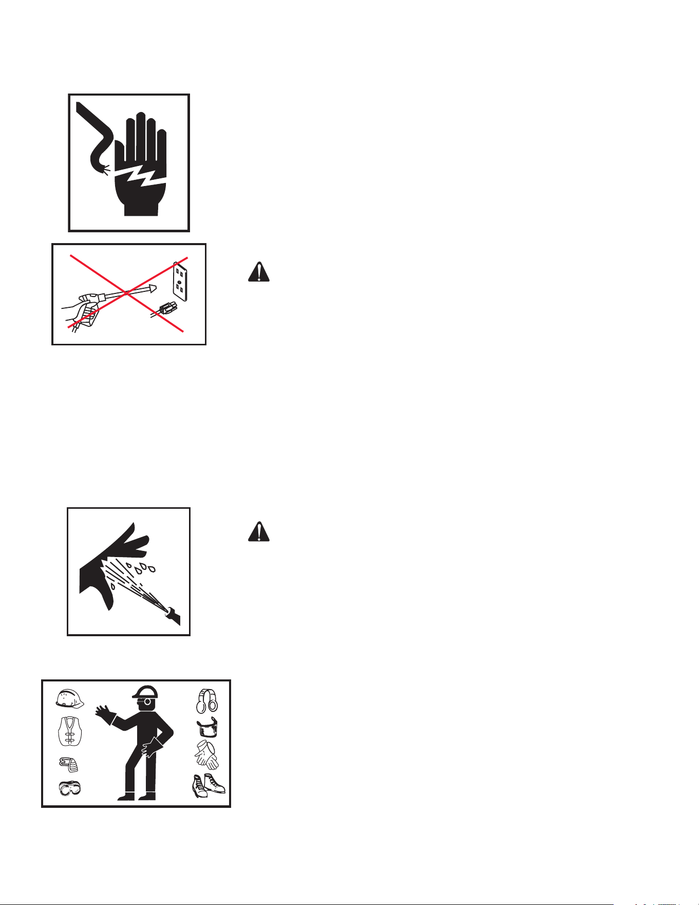
1. GROUNDING INSTRUCTIONS: This product must be grounded. If it should
malfunction or breakdown, grounding provides a path of least resistance
for electric current to reduce the risk of electric shock. This product is
equipped with a cord having an equipment-grounding conductor and a
grounding plug. The plug must be plugged into an appropriate outlet that
is properly installed and grounded in accordance with all local codes and
ordinances.
2. DANGER: Improper connection of the equipment-grounding conductor
can result in a risk of electrocution. Check with a qualied electrician or
service personnel if you are in doubt as to whether the outlet is properly
grounded. Do not modify the plug provided with the product - if it will not
t the outlet, have a proper outlet installed by a qualied electrician. Do
not use any type of adaptor with this product.
WARNING TO REDUCE THE RISK OF ELECTROCUTION, KEEP ALL
CONNECTIONS DRY AND OFF THE GROUND.DO NOT TOUCH
PLUG WITH WET HANDS.
3. DO NOT pull on the electrical cord to disconnect from the outlet.
4. Check power cord for damage before using. There is a hazard of electrical
shock from crushing, cutting or heat damage.
5. Always be certain the unit is receiving proper voltage. Before plugging the
unit into a compatible power source, be certain the switch is in the "OFF"
position. Disconnect when not in use.
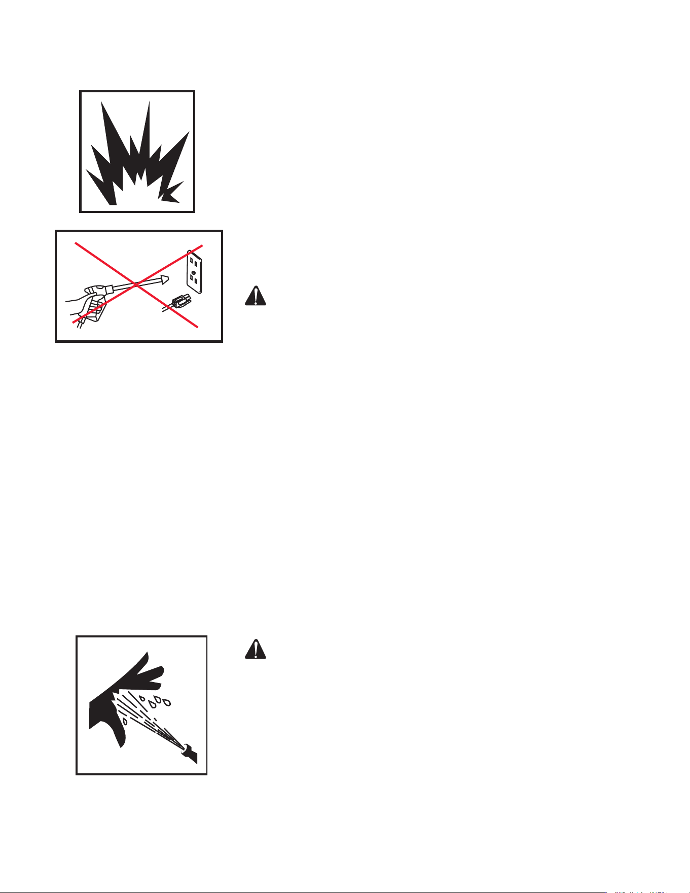
6. DO NOT use the unit in an area where ammable gas vapors may be
present. An electric spark could cause an explosion or re.
7. DO NOT direct water spray on or into electrical installations of any kind.
This includes electrical outlets, light bulbs, fuse boxes, transformers, the
unit itself, etc. Severe electrical shock may occur.
8. The manufacturer does not recommend that the owner attempt any electrical
repairs to this unit.spray precautions:
RISK OF INJECTION
DANGER OR SEVERE CUTTING INJURY KEEP CLEAR OF NOZZLE.
DO NOT DIRECT DISCHARGE STREAM AT PERSONS OR PETS.
ONLY TRAINED OPERATORS SHOULD USE THIS PRODUCT.
BASIC PRECAUTIONS SHOULD ALWAYS BE OBSERVED,
INCLUDING THE FOLLOWING:
1. KEEP AWAY FROM THE SPRAY:
a. Because of the high pressure and velocity of the spray, uids can
penetrate the skin, causing serious injury.
b. Never point the gun at yourself or anyone else. Never put your hand,
ngers or body directly over the spray nozzle. Always keep operating
area clear of all persons. Use extreme caution when operating near
children.
c. If an accident does occur and the spray appears to have penetrated
the skin, SEEK EMERGENCY MEDICAL CARE. DO NOT TREAT AS A
SIMPLE CUT.
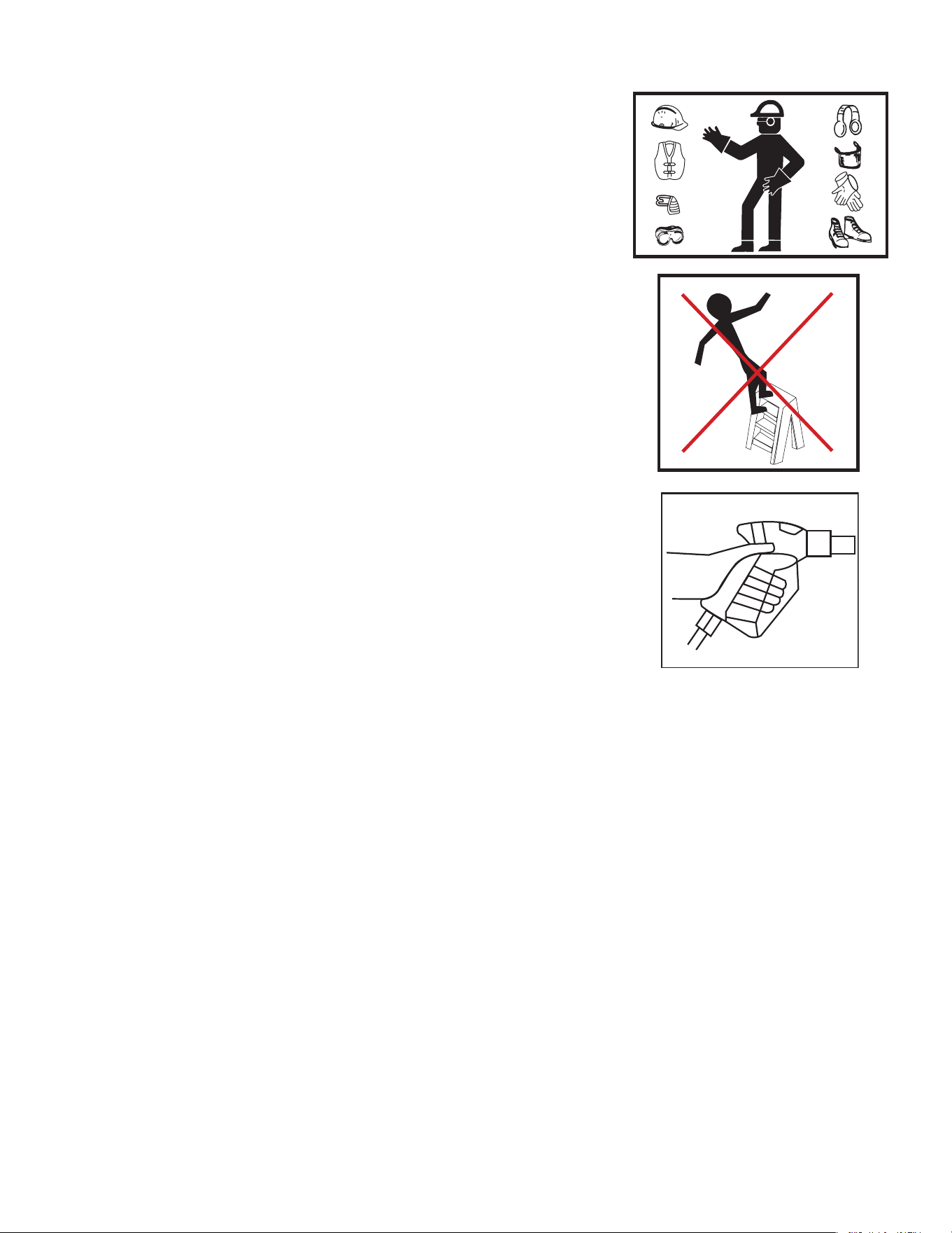
2. ALWAYS wear protective goggles when operating the unit to shield the
eyes from ying debris and detergents. Other protective equipment such
as rubber suits, gloves and boots are advisable. Use extreme caution when
operating near children.
3. Stay alert-watch what you are doing. Do not operate the unit when fatigued
or under the inuence of alcohol or drugs.
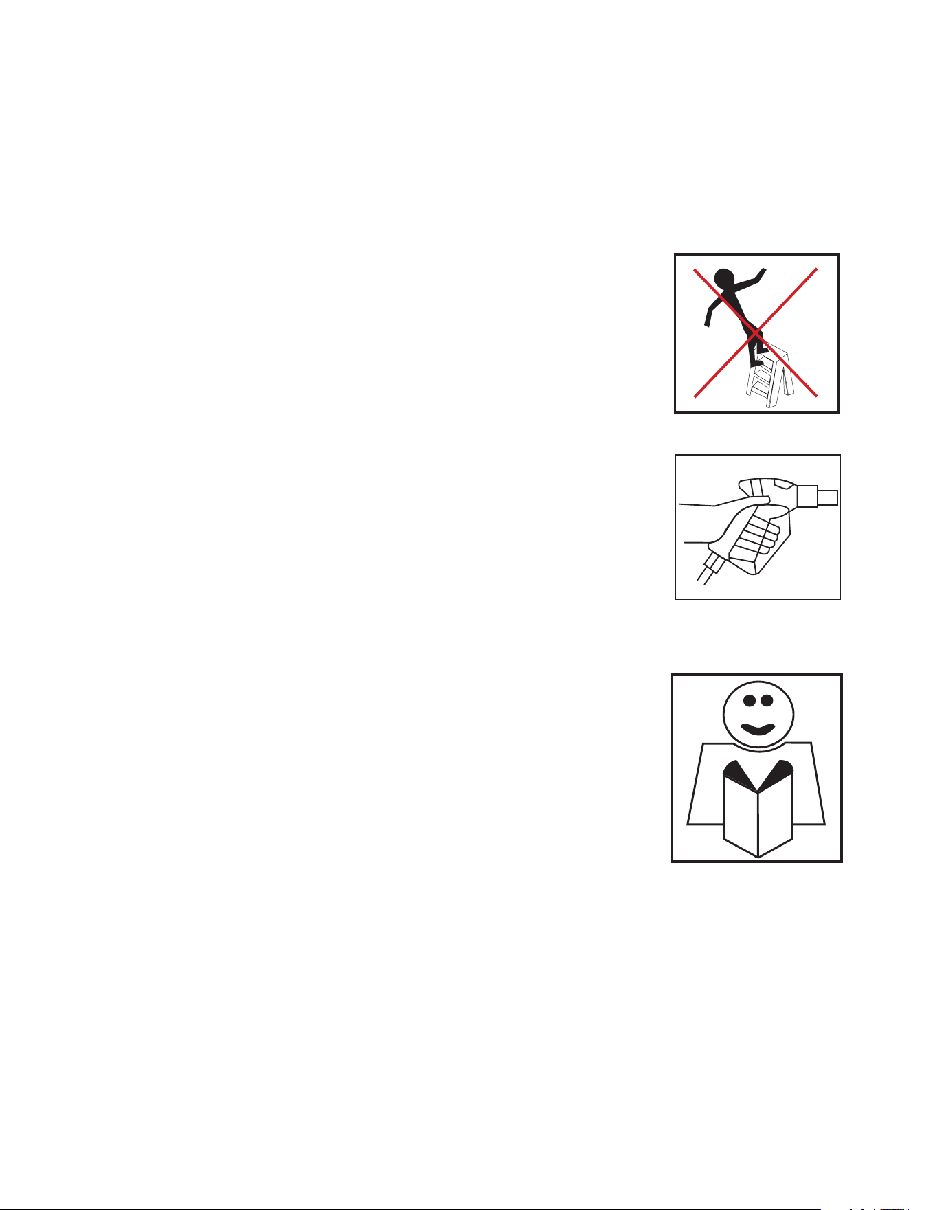
4. NEVER squeeze the trigger unless securely braced. The thrust from the
water traveling through the nozzle may be powerful enough to cause the
Operator's Manual 5
IMPORTANT SAFETY INSTRUCTIONS
operator to lose balance if unprepared. DO NOT overreach or stand on
unstable support. Wet surfaces can be slippery, wear protective foot gear
and keep good footing and balance at all times. NEVER trigger the gun
while on a ladder or roof.
5. Caution should be used when directing spray toward fragile materials such
as glass. Shattering could result in serious injury.
6. ALWAYS hold on rmly to the gun/wand assembly when starting and
operating the unit. Failure to do so can cause the wand to fall and whip
dangerously.
MISCELLANEOUS SAFETY PRECAUTIONS:
1. NEVER ALLOW CHILDREN OR ADOLESCENTS TO OPERATE THIS UNIT!
2. Read and follow all handling, operations, maintenance and safety instructions
listed in this manual and provide such information to ANYONE who will be
operating this unit.
3. In freezing temperatures, the unit must always be warm enough to ensure
there is no ice formation in the pump. DO NOT start this unit if it has been
transported in an open or underheated vehicle without rst allowing the
pump to thaw.
4. High pressure hoses should be inspected daily for signs of wear. If
evidence of failure exists, promptly replace all suspect hoses to prevent
the possibility of injury from the high pressure spray. If a hose or tting is
leaking , NEVER place your hand directly on the leak.
5. DO NOT operate the unit if you see any pump oil or water leaks from the
machine. DO NOT resume operation until the unit has been inspected and
repaired by a qualied service person.
6. DO NOT operate the unit without all protective covers in place.
7. To reduce the risk of injury, maintain a safe distance from persons while
operating this unit. Close supervision is necessary when operating the
unit near children.
8. Shut off the unit power switch before leaving.
ADJUSTMENT PRECAUTIONS:
1. NEVER alter or modify the equipment, be sure any accessory items and
system components being used will withstand the pressure developed.
Use ONLY genuine manufacturer parts for repair of your pressure washer.
Failure to do so can cause hazardous operating conditions and will void
warranty.
2. NEVER make adjustments to the machinery while it is connected to the
power source.
3. Know how to stop the pressure washer quickly. Be thoroughly familiar
with controls.
4. Before servicing the unit; turn the unit off, relieve the water pressure, and
allow the unit to cool down. Service in a clean, dry, at area.
5. Follow the maintenance instructions specied in this manual.
6 Operator's Manual
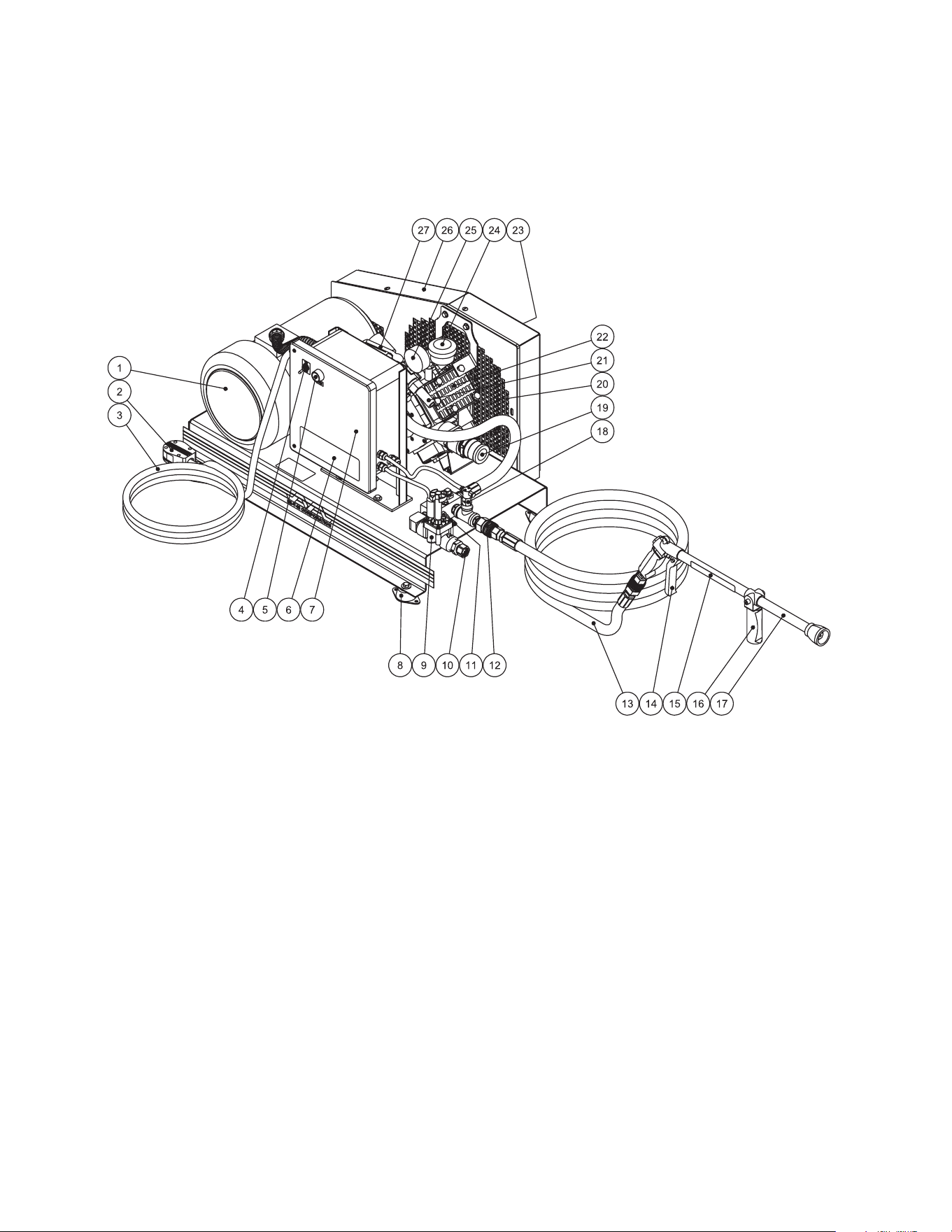
FEATURES FOR CHV-0525-0ME1/0ME3
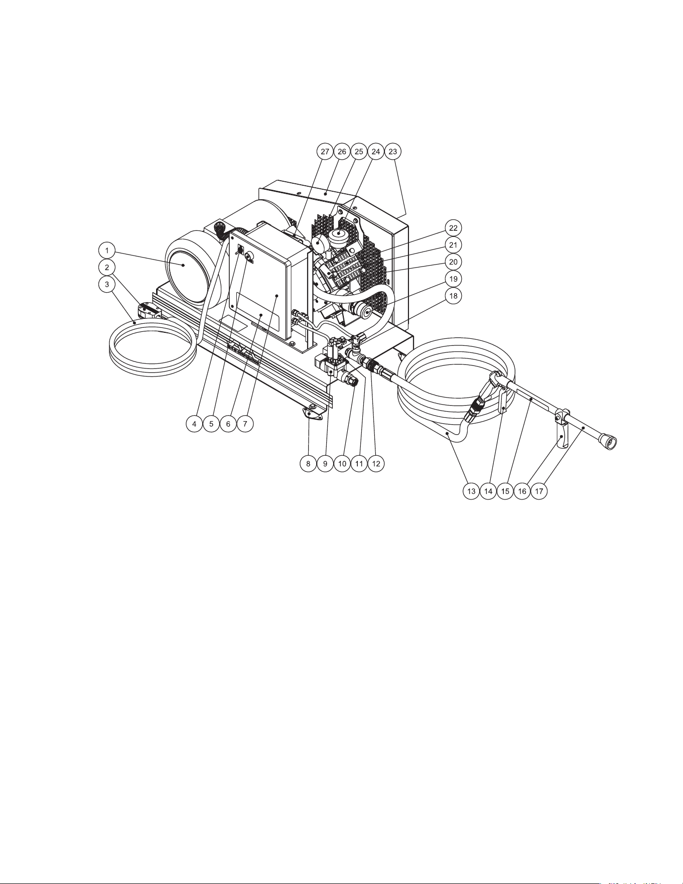
FEATURES LISTING
CHV-EEATURES-091106-JJT
1. Motor
2. Electric Plug
3. Power Cord
4. Power Switch
5. Start Button
6. Decal-Warning/Caution/Operation
7. Electric Box
8. Dome Isolator
9. Solenoid Valve
10. Garden Hose Connection
11. Fresh Water Outlet - To Tank
12. High Pressure Outlet
13. High Pressure Hose
14. Gun Trigger
15. Decal - Warning Risk of Injection
16. Adjustable Spray Pattern Lever
17. Long Range Gun w/Nozzle
18. Mini Flow Switch
19. Pump Inlet
20. Ventilation Openings
21. By-Pass Outlet
22. Diaphragm Pump
23. Decal - Beltguard in Place
24. Oil Fill/Sightglass
25. Outlet Pressure Guage
26. Beltguard
27. Dump Lever
Operator's Manual 7
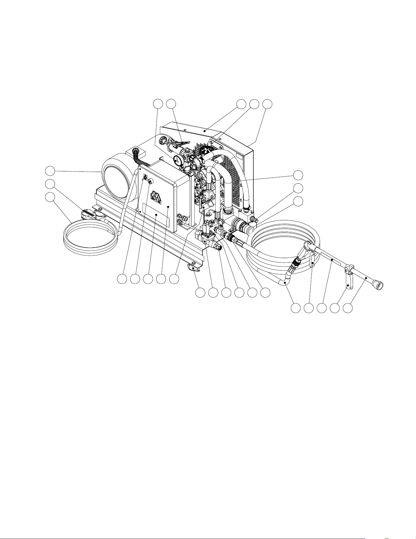
FEATURES FOR CHV-0525-1ME1/1ME3
FEATURES LISTING
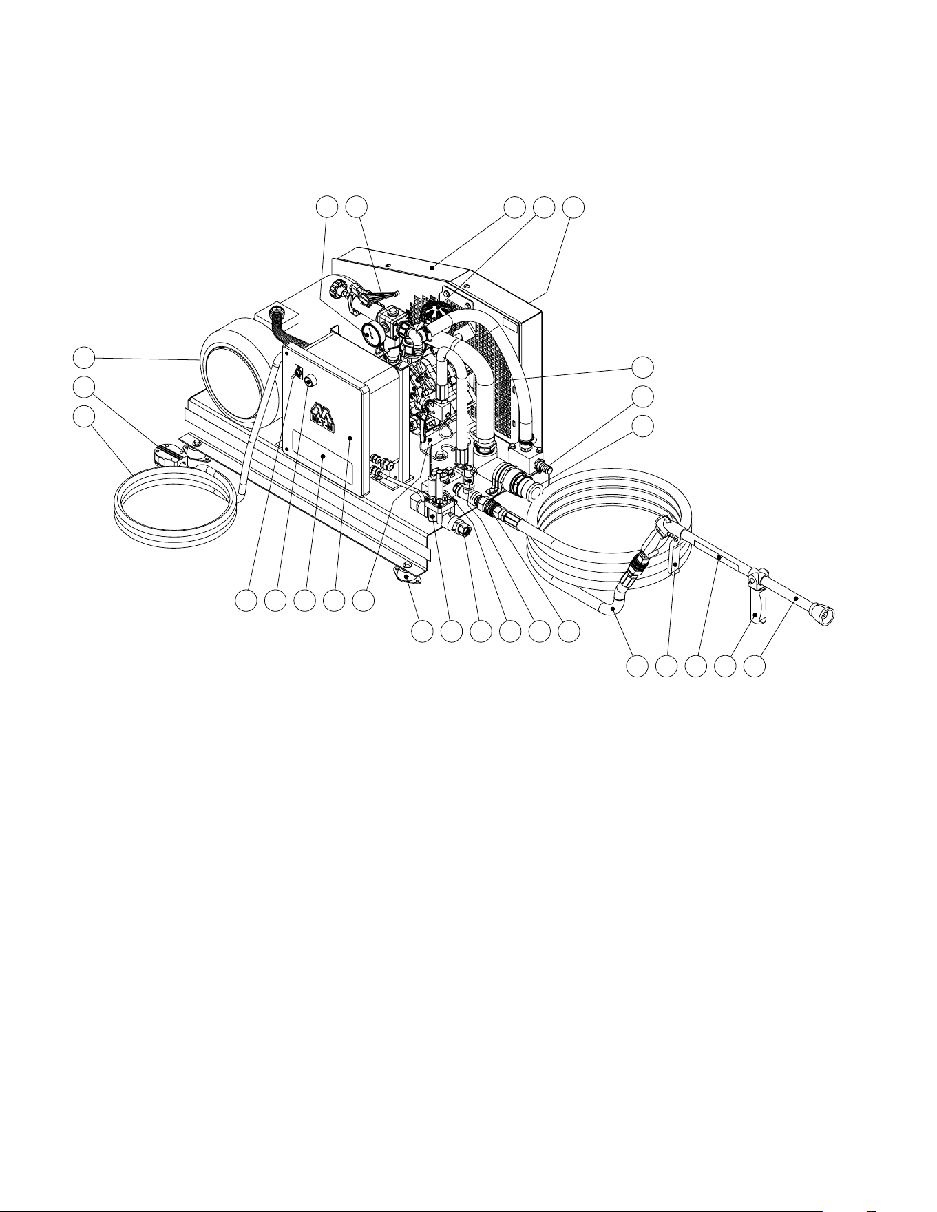
CHV AR PUMP FEATURES 112420
3
2
1
4
5
6 7
9 10 11
12
14
15 16 17 18 19
20
21
8
22
2324
27 26
25
13
1. Motor
2. Electric Plug
3. Power Cord
4. Power Switch
5. Start Button
6. Decal - Warning/Caution/Operation
7. Electric Box
8. Diaphragm Pump
9. Dome Isolator
10. Solenoid Valve
11. Garden Hose Connection
12. Fresh Water Outlet - To Tank
13. Mini Flow Switch
14. High Pressure Outlet
15. High Pressure Hose
16. Gun Trigger
17. Decal - Warning Risk Of Injection
18. Adjustable Spray Pattern Lever
19. Long Range Gun W/Nozzle
20. Pump Inlet
21. By-Pass Outlet
22. Ventilation Openings
23. Decal - Beltguard In Place
24. Oil Fill/Sightglass
25. Beltguard
26. Dump Lever
27. Outlet Pressure Gauge
8 Operator's Manual
SAFETY DECALS & PLACEMENT
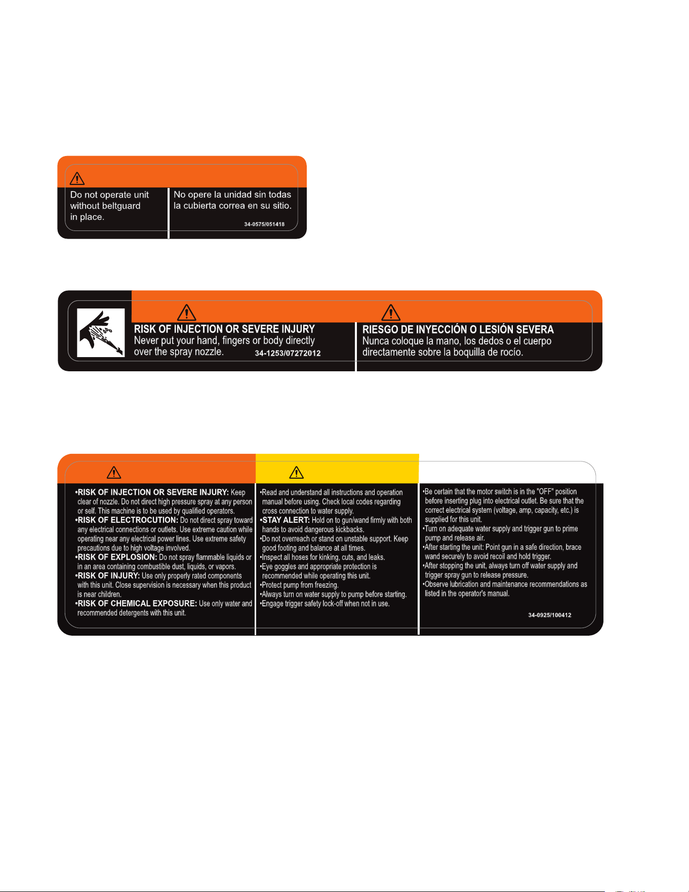
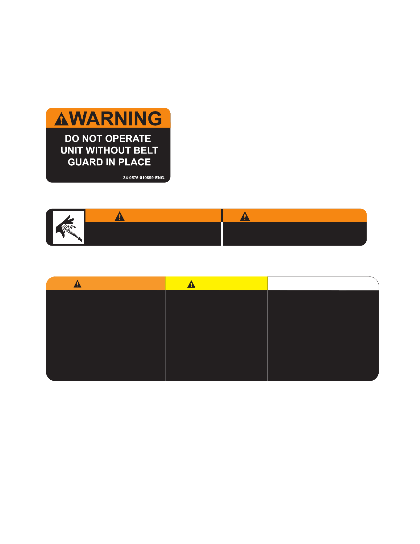
Decal: Warning: Beltguard in Place
(Part #34-0575)
Decal: Warning/Caution/Operating Instructions (Part #34-0925)
•RISK OF INJECTION OR SEVERE INJURY: Keep
clear of nozzle. Do not direct high pressure spray at any person
or self. This machine is to be used by qualified operators.
•RISK OF ELECTROCUTION: Do not direct spray toward
any electrical connections or outlets. Use extreme caution while
operating near any electrical power lines. Use extreme safety
precautions due to high voltage involved.
•RISK OF EXPLOSION: Do not spray flammable liquids or
in an area containing combustible dust, liquids, or vapors.
•RISK OF INJURY: Use only properly rated components
with this unit. Close supervision is necessary when this product
is near children.
•RISK OF CHEMICAL EXPOSURE: Use only water and
recommended detergents with this unit.
•Read and understand all instructions and operation
manual before using. Check local codes regarding
cross connection to water supply.
•STAY ALERT: Hold on to gun/wand firmly with both
hands to avoid dangerous kickbacks.
•Do not overreach or stand on unstable support. Keep
good footing and balance at all times.
•Inspect all hoses for kinking, cuts, and leaks.
•Eye goggles and appropriate protection is
recommended while operating this unit.
•Protect pump from freezing.
•Always turn on water supply to pump before starting.
•Engage trigger safety lock-off when not in use.
•Be certain that the motor switch is in the "OFF" position
before inserting plug into electrical outlet. Be sure that the
correct electrical system (voltage, amp, capacity, etc.) is
supplied for this unit.
•Turn on adequate water supply and trigger gun to prime
pump and release air.
•After starting the unit: Point gun in a safe direction, brace
wand securely to avoid recoil and hold trigger.
•After stopping the unit, always turn off water supply and
trigger spray gun to release pressure.
•Observe lubrication and maintenance recommendations as
listed in the operator's manual.
WARNING
CAUTION
OPERATION
34-0925/100412
DO NOT REMOVE SAFETY DECALS FROM UNIT UNLESS REPLACING WITH MOST CURRENT SAFETY DECAL!!
Decal: Warning: Risk of Injection (Part #34-1253)
34-0575/051418
WARNING/ADVERTENCIA
No opere la unidad sin todas
la cubierta correa en su sitio.
Do not operate unit
without beltguard
in place.
No opere la unidad sin todas
la cubierta correa en su sitio.
Do not operate unit
without beltguard
in place.
RISK OF INJECTION OR SEVERE INJURY
Never put your hand, fingers or body directly
over the spray nozzle.
34-1253/07272012
RIESGO DE INYECCIÓN O LESIÓN SEVERA
Nunca coloque la mano, los dedos o el cuerpo
directamente sobre la boquilla de rocío.
WARNING
ADVERTENCIA
Operator's Manual 9
INSTALLATION & PREPARATION
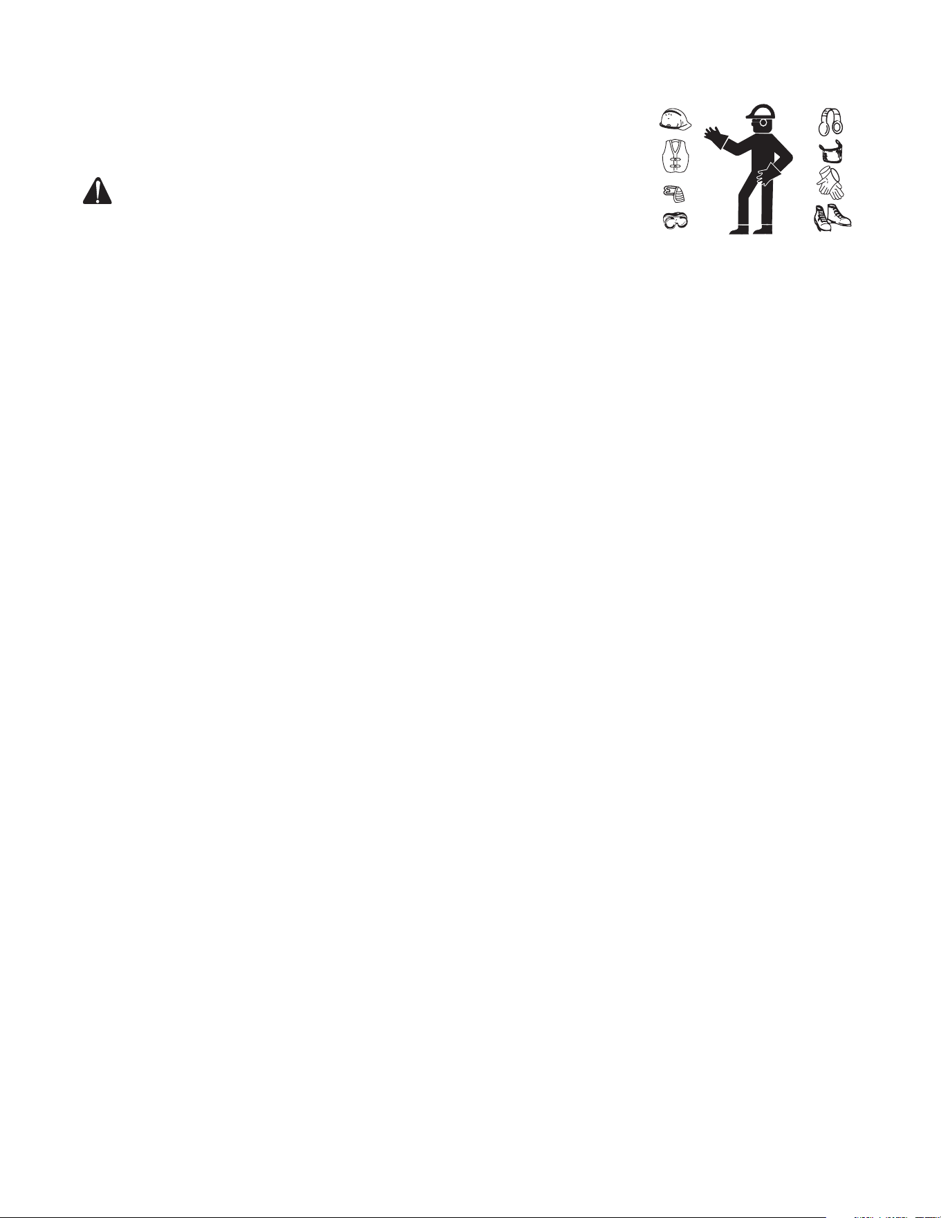
ATTIRE:
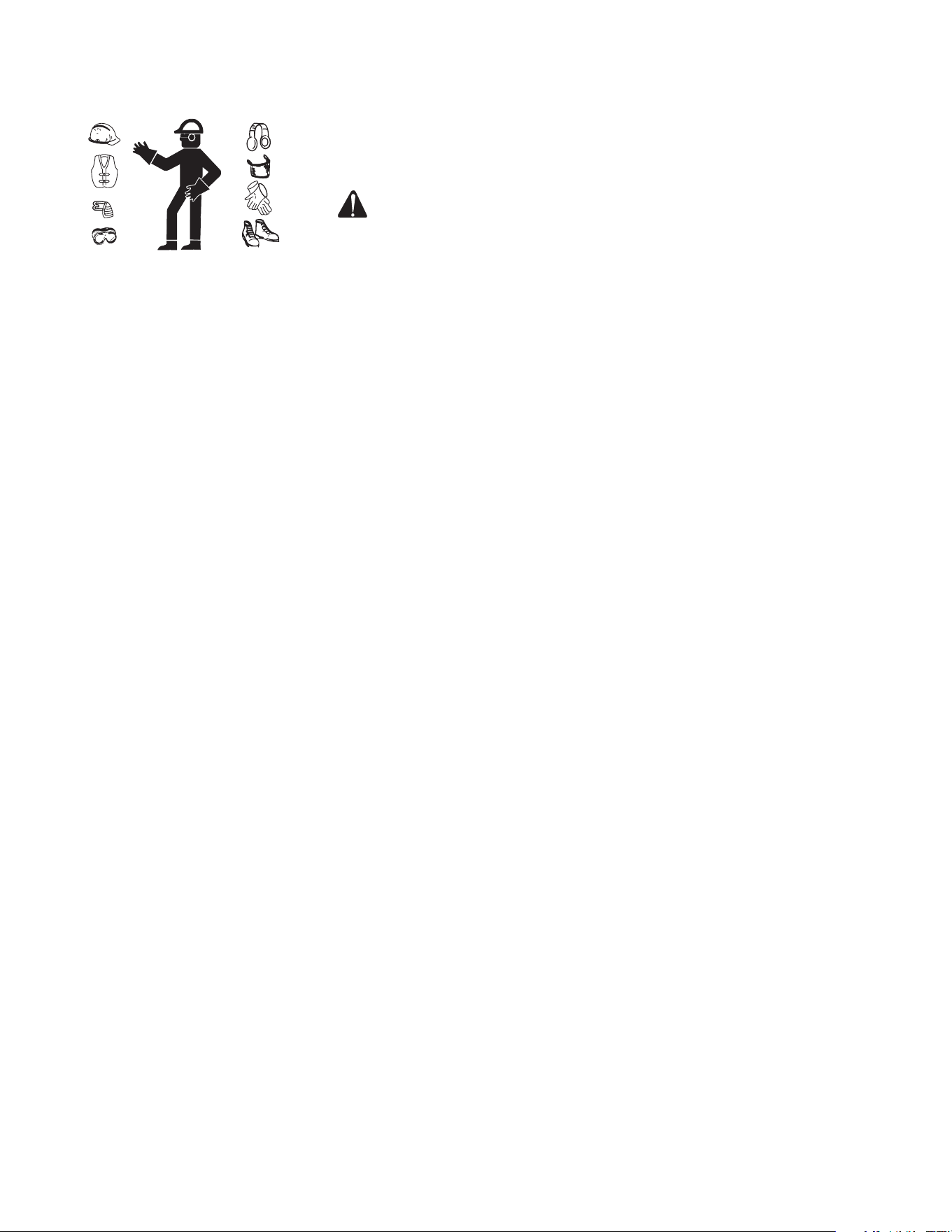
Proper attire is essential to your safety. Utilize whatever means necessary to
protect eyes, ears, and skin.
SETUP:
WARNING RISK OF EXPLOSION OR FIRE! DO NOT OPERATE
UNIT IN AN AREA WHERE FLAMMABLE GAS VAPORS MAY BE
PRESENT. A SPARK CAN CAUSE AN EXPLOSION OR FIRE!
RISK OF UNIT BURSTING! DO NOT STORE OR OPERATE UNIT IN A
FREEZING ENVIRONMENT!
1. This u nit should only be placed on a level surface to ensure proper lubrication
for the water pump while operating. NEVER spray water directly on the
unit!
2. DO NOT place unit in an area:
a. where there is evidence of oil or gas leaks
b. where ammable vapors may be present.
3. Do not allow the unit to be exposed to rain, snow or freezing temperatures.
If any part of the unit becomes frozen; excessive pressure may build up in
the unit which could cause it to burst which could result in serious injury
to the operator or bystanders.
4. Pump oil level should be checked before each use to be certain the oil
level is in the center of the sight glass. If low, ll with oil. (See pump Data
Plate for oil type). DO NOT OVERFILL!
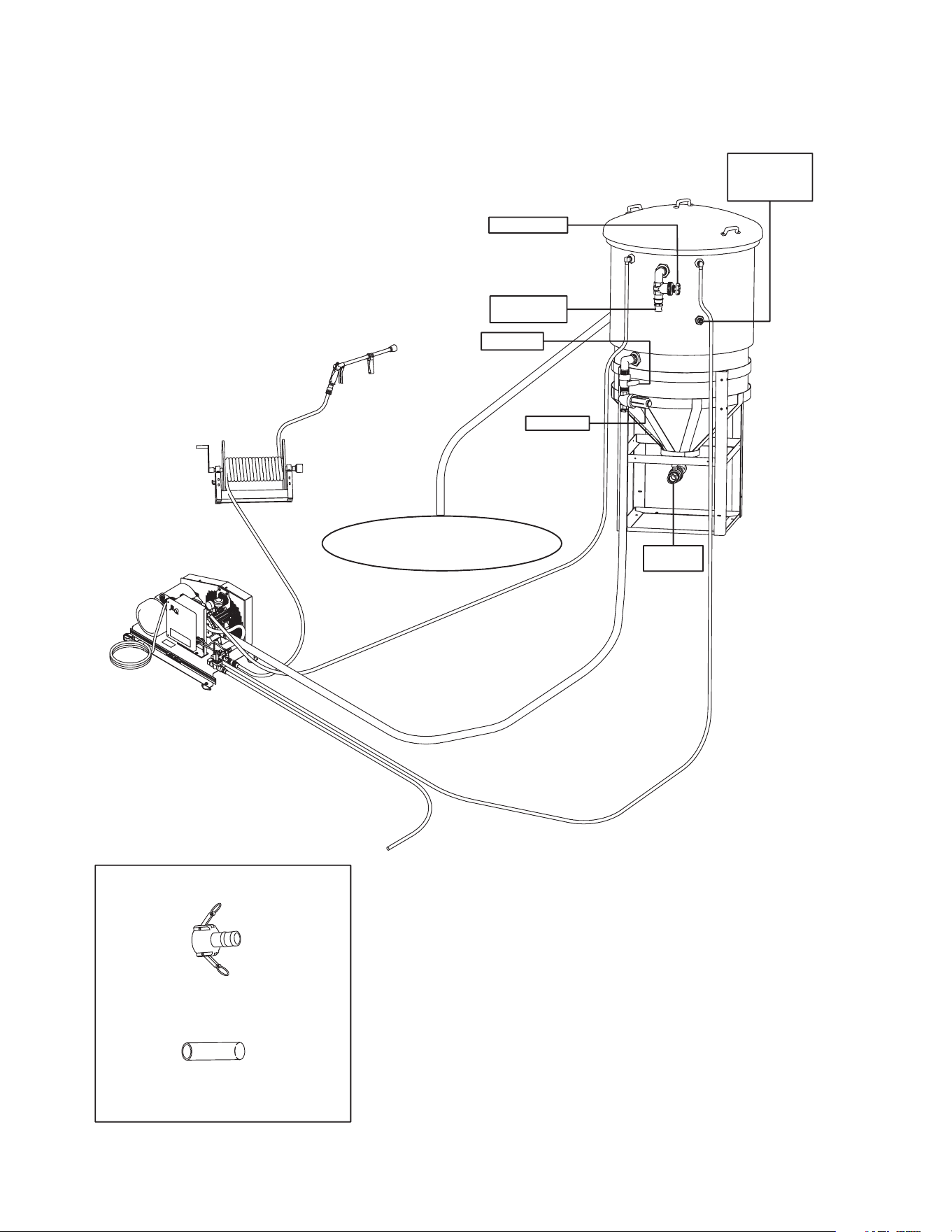
TYPICAL WATER SUPPLY HOOKUP:
1. Select a Garden hose measuring at least 3/4" ID and no longer than 50
feet. Connect one end of the MAKE-UP water supply garden hose to the
MAKE-UP water inlet of the unit. Connect the other end of the hose to
your pressurized water supply.
Note: When connecting the make-up water inlet to the water supply
mains, local regulations of your water company must be observed.
In some areas, the unit must not be connected directly to the public
drinking water supply. This is to ensure that there is no feedback
into the water supply. (Direct connection is permitted if a back flow
preventer is installed.)
2. Connect the make-up water hose from unit to tank. (Optional CX-0072
tank) Twenty ve feet of 3/4” low pressure hose #15-0033 is supplied
with the unit. The makeup water supply alone will not supply the water
requirements of the unit.
Note: The diaphram pump will not suffer if run dry due to any empty
tank. However a starved suction due to a clogged strainer or closed
valve in the pump inlet line will cause premature failure of the pump
diaphrams.
3. Connect a 1-1/2 inch non collapsable inlet hose from the tank to the
pump inlet. Hose and connectors are not supplied with unit. 1-1/2” Non
collapsable hose #15-0212 and 1-1/2” cam and groove connector #55-0053
(two required) can be purchased separately. Twenty ve feet of hose with
connectors is supplied with CX-0072. Typical installation includes a shut
off ball valve (suction valve) and a large area lter with 10-20 mesh screen
(included with CX-0072). Never use a ne lter screen with a diaphram
pump.
4. Connect bypass outlet hose from pump to tank. Twenty ve feet of 3/4”
low pressure hose #15-0033 (50 ft total) is supplied with the unit.
5. Quick-connect the high pressure discharge hose to the water outlet of the
unit. Connect the other end of the discharge hose to the gun.
6. A sump pump from a pit or recycle system is typically routed to the tank to
provide enough water to keep the tank from running out. (Not Provided)
7. An overow hose from the top of the tank is typically routed back to the pit.
10 Operator's Manual
INSTALLATION & PREPARATION
3/4" GARDEN HOSE TO
MAKEUP WATER INLET
3/4" LOW PRESSURE HOSE TO
MAKEUP WATER TANK INLET
25' WITH UNIT (15-0033)
CHV NONCOLLAPSABLE
25' INLET HOSE
WITH CX-0072 (15-0212)
3/4" LOW PRESSURE
BY-PASS OUTLET HOSE
25' WITH UNIT (15-0033)
HIGH PRESSURE
50 FT. OUTLET HOSE
(WITH UNIT)
OPTIONAL HOSE
REEL 50-0185
LONG RANGE GUN
WITH NOZZLE
(WITH UNIT)
OPTIONAL
WATER HOLDING
TANK CX-0072
TYPICAL INSTALL
OVERFLOW HOSE
CHV UNIT
BALL VALVE
INLET FILTER
TYPICAL FROM
SUMP PUMP
FLOAT VALVE
IN TANK
FIELD INSTALLED
WIRING
SHUTOFF VALVE
SLUDGE
DISCHARGE
WATER RECYCLE
SYSTEM / PIT / SUMP PUMP
SOLD SEPARATELY
1 1/2" CAM AND GROOVE ADAPTER
QTY. 2 WITH CX-0072 (55-0053)
1 1/2" SUCTION HOSE ORDERED PER FT.
25' WITH CX-0072 OPTION (15-0212)
Operator's Manual 11
INSTALLATION & PREPARATION
CONTROL UNIT:
The pressure has been preset at the factory and should only be adjusted by
a trained Customer Service Representative.
PULSATION DAMPENER:
It is the nature of diaphragm pumps to have some pulsation. This is caused
by sudden changes in piston direction. The pulsation dampener has one
function in the pumping system, reduce pulsation by providing a cushion of
air to bump against. The pulsation dampener uses a rubber bladder to sepa-
rate the air cushion from the solution being pumped.
The basic rule is to ll the pulsation dampener to twenty percent (20%) of the
system working pressure. If you have your spraying pressure set at 100 psi,
the setting for the pulsation dampener should be 20 psi. Always shut down
the pump before adding air to the pulsation dampener or checking its pres-
sure. Air supply can be from a compressor or a manual type pump. The dome
containing air is small. Take care to apply the pressure guage evenly on the
air valve to prevent air from leaking out of the pulsation dampener. It is not
uncommom to lose 5-10 psi when checking pulsation dampener pressure.
NOTE: 2-cylinder diaphragm pumps may require more air than 20%
of operating pressure. 20 psi is the minimum pulsation dampener
pressure. DO NOT RUN PUMP WITH LESS THAN 20 PSI IN THE
PULSATION DAMPENER.
POWER CORD CONNECTION:
WARNING RISK OF ELECTROCUTION! THIS UNIT MUST BE
CONNECTED TO A PROPERLY GROUNDED OUTLET. DO NOT
USE AN ADAPTER OR REMOVE THE GROUNDING PRONG.
1. Make certain the motor switch is in the "OFF" position.
2. Ensure electrical supply matches that shown on identication plate located
on unit base plate.
3. Ensure the area between the pressure washer cord and the outlet is kept dry.
4. Insert the male plug into a properly grounded AC outlet. DO NOT use an
adapter OR remove the grounding prong!
PRE-START INSPECTION PROCEDURES:
Before starting the unit, perform the following procedures:
1. Check the oil level in the pump.
2. Inspect the inlet water strainer (not supplied with unit/with cx-0072). Clean
or replace if necessary.
3. Check all hose connections to ensure they are securely tightened.
4. Open Suction Valve and check tightness of suction lines, ttings and lter.
5. Inspect for system water leaks and oil leaks. Be sure that all damaged
parts are replaced and that the mechanical problems are corrected prior to
operation of the unit. If service is needed, contact an Authorized Service
Center.
6. The diaphragm pump will not suffer if run dry due to an empty tank. However,
a "starved" suction due to a clogged strainer or closed suction valve will
cause premature failure of the pump diaphragm pump.
7. Inspect high pressure hose for kinking, cuts or leaks. If a cut or leak
is found, DO NOT USE HOSE! Replace hose before starting unit. See
"Miscellaneous Safety Precautions" #4. Be sure that all damaged parts are
replaced and that the mechanical problems are corrected prior to operation
of the unit. If you need service, contact an Authorized Service Center.
8. Inspect electrical cord for cuts. If a cut is found, DO NOT TOUCH OR USE
ELECTRICAL CORD! Replace cord before starting the unit.

12 Operator's Manual
WARNING
THE FOLLOWING PAGES CONTAIN OPERATING AND MAINTENANCE INSTRUCTIONS.
DO NOT ATTEMPT TO OPERATE THIS PRESSURE WASHER UNTIL YOU HAVE READ
AND UNDERSTOOD ALL SAFETY PRECAUTIONS AND INSTRUCTIONS LISTED IN THIS
MANUAL.
INCORRECT OPERATION OF THIS UNIT CAN CAUSE SERIOUS INJURY!!
DO NOT ALTER OR MODIFY THIS EQUIPMENT IN ANY MANNER!
Operator's Manual 13
OPERATING INSTRUCTIONS
START-UP:
1. Refer to the "Safety Precautions" before starting the unit.
2. Lay the high pressure hose out to remove any loops. Water ow will
constrict the hose creating tight loops if the hose is not straight.
3. Securely connect the gun/wand assembly to the high pressure hose.
4. Push the manual dump valve lever down so the pump will start in bypass
mode. Turn the water supply completely on.
DANGER RISK OF INJECTION CAUSING SEVERE INJURY! -KEEP
CLEAR OF NOZZLE! NEVER PLACE HAND OR FINGERS IN
FRONT OF NOZZLE! -DO NOT DIRECT DISCHARGE STREAM
AT PEOPLE OR PETS! -BE CERTAIN THE NOZZLE IS SECURELY
CONNECTED TO THE WAND TO PREVENT ACCIDENTAL
DISCHARGE.
5. The diaphragm pump will not suffer if run dry due to an empty tank. However
a “starved” suction due to a clogged strainer screen or a closed suction
valve will cause premature failure of the pump diaphragms. Important:
keep suction valve open whenever system is being operated
6. Move the toggle switch to the "ON" position and push the green start
button to turn on the unit.
7. Water will begin owing through the bypass hose back to the water supply
tank. This allows the unit to prime and purge any air from the system. The
unit is primed when water ow is uninterrupted by air.
8. Return dump valve lever to the "UP" position.
9. Point the gun in a safe direction and squeeze the trigger. Brace yourself,
as the gun will kickback from the force of the water exiting the nozzle.
10. Once the unit is turned on, perform the following procedures with the gun
open:
a. Inspect for system water leaks and oil leaks. If a leak is found, TURN
the UNIT OFF! Be sure that all damaged parts are replaced and that
the mechanical problems are corrected prior to operation of the unit.
If you require service, contact Customer Service.
b. Inspect high pressure hose for kinking cuts and leaks. If a cut or leak
is found, DO NOT TOUCH HOSE AT CUT OR LEAK!!! TURN the UNIT
OFF! Replace hose before restarting the unit. Be sure that all damaged
parts are replaced and that the mechanical problems are corrected
prior to operation of the unit. If you require service, contact Customer
Service.
c. Inspect electrical cord for cuts. If a cut is found, DO NOT TOUCH
ELECTRICAL CORD AT CUT!!! TURN UNIT OFF IMMEDIATELY!
11. Trigger the gun several times. NEVER look directly into the nozzle! High
pressure water creates a risk of severe injury!
CAUTION RISK OF DAMAGE. DO NOT ALLOW SPRAY PATTERN
TO REMAIN ON A FIXED AREA FOR AN EXTENDED PERIOD OF
TIME. POSSIBLE DAMAGE MAY OCCUR TO THE AREA.
SHUTDOWN:
1. The unit is equipped with time delay shutdown. It will shut down automatically
when the gun has not been triggered for the duration of the timer setting.
2. Move the toggle switch to the "OFF" position to turn unit power off before
leaving the unit. Do not leave the unit unattended without turning the toggle
switch to the off position. The unit may restart for a short period of time
after the time delay shutdown is activated if the gun trigger is squeezed
during that time.
3. Disconnect the unit from the power source.

14 Operator's Manual
OPERATING INSTRUCTIONS
4. Turn garden hose make up water supply "OFF".
5. Pointing the gun in a safe direction, trigger gun to ensure there is no trapped
pressure.
6. Disconnect and drain the gun, wand and hoses.
7. Wipe unit clean. Store the gun, wand and hoses in a safe area.
Operator's Manual 15
STORAGE & MAINTENANCE
BELT TENSION ADJUSTMENT
SPECIFIC MAINTENANCE:
PUMP: If oil appears dirty or milky, change oil. See pump Data Plate for oil
type. Fill only to the center of the oil sight glass. Change Pump diaphragms
every 500 hours. Inspect check valves for spring fatigue and seat wear.
QUICK COUPLERS: There is an o-ring seal inside the female quick-coupler.
This o-ring will deteriorate or, if the unit is allowed to pump without the high
pressure hose attached, it may be blown out occasionally. Simply insert a
replacement o-ring to correct the leak. (New o-rings can be purchased from
your dealer.)
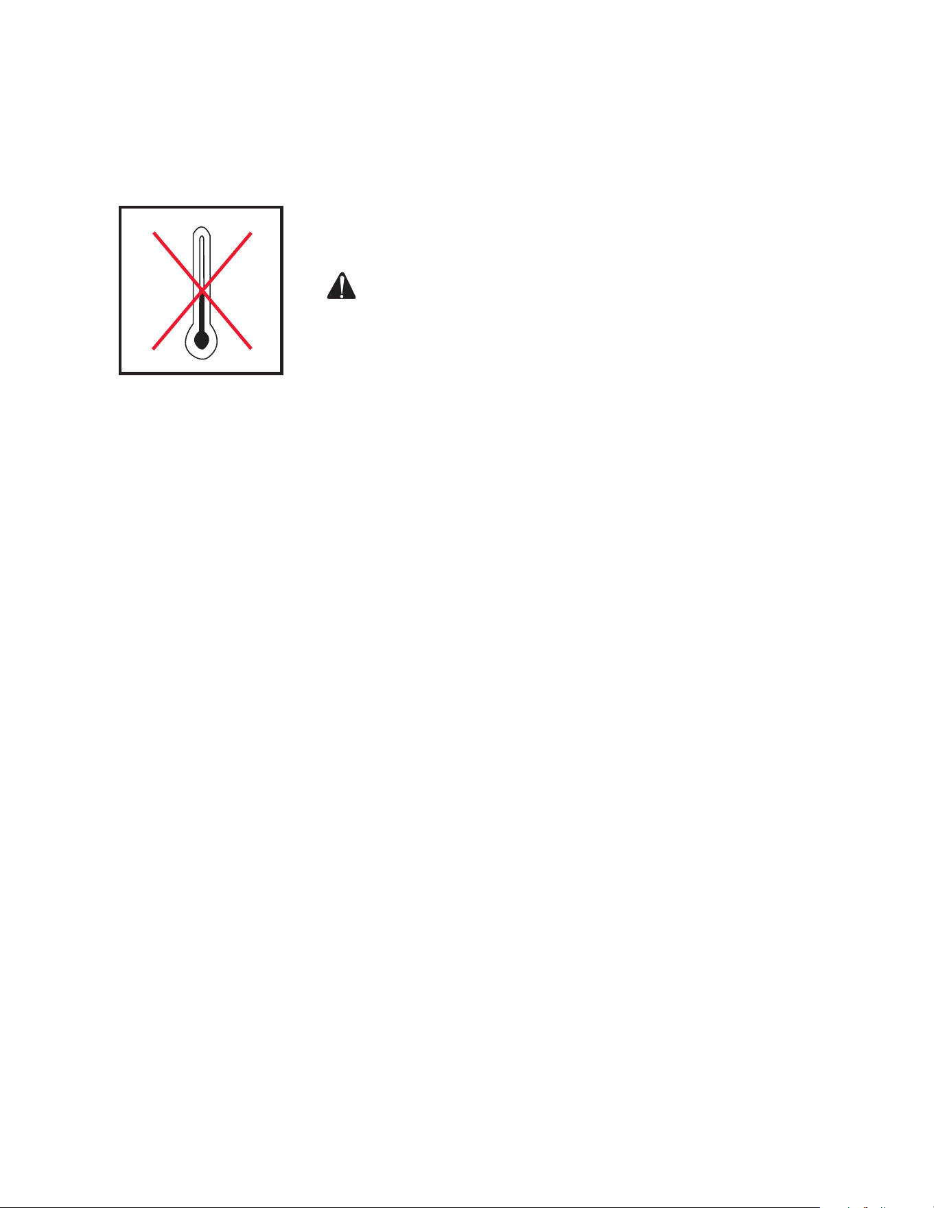
BELT TENSION ADJUSTMENT: To maintain peak performance of your
pressure washer, it may be necessary to adjust the belt tension on occasion.
Follow the procedure outlined below.
1. Remove the belt guard and loosen the two nuts on each side of the motor.
(Reference A) There are a total of 4 nuts.
2. Turn the cap screw (Reference B) clockwise until a 1/2 inch belt deection
is noticed between the pulleys.
3. Tighten the motor nuts. (Reference A)
4. Put a straight edge across both pulleys to check belt alignment.
5. Replace the beltguard and tighten the fasteners securely.
A
B
16 Operator's Manual
STORAGE & MAINTENANCE
WINTERIZING:
For storage and transportation purposes in subfreezing ambient tempera-
tures, it will be necessary to winterize this unit. This unit must be protected
to the lowest incurred temperature for the following reasons:
1. If any part of the pumping system becomes frozen; excessive pressure
may build up in the unit which could cause the unit to burst resulting in
possible serious injury to the operator or bystanders.
2. The pumping system in this unit may be permanently damaged if frozen.
FREEZE DAMAGE IS NOT COVERED BY WARRANTY.
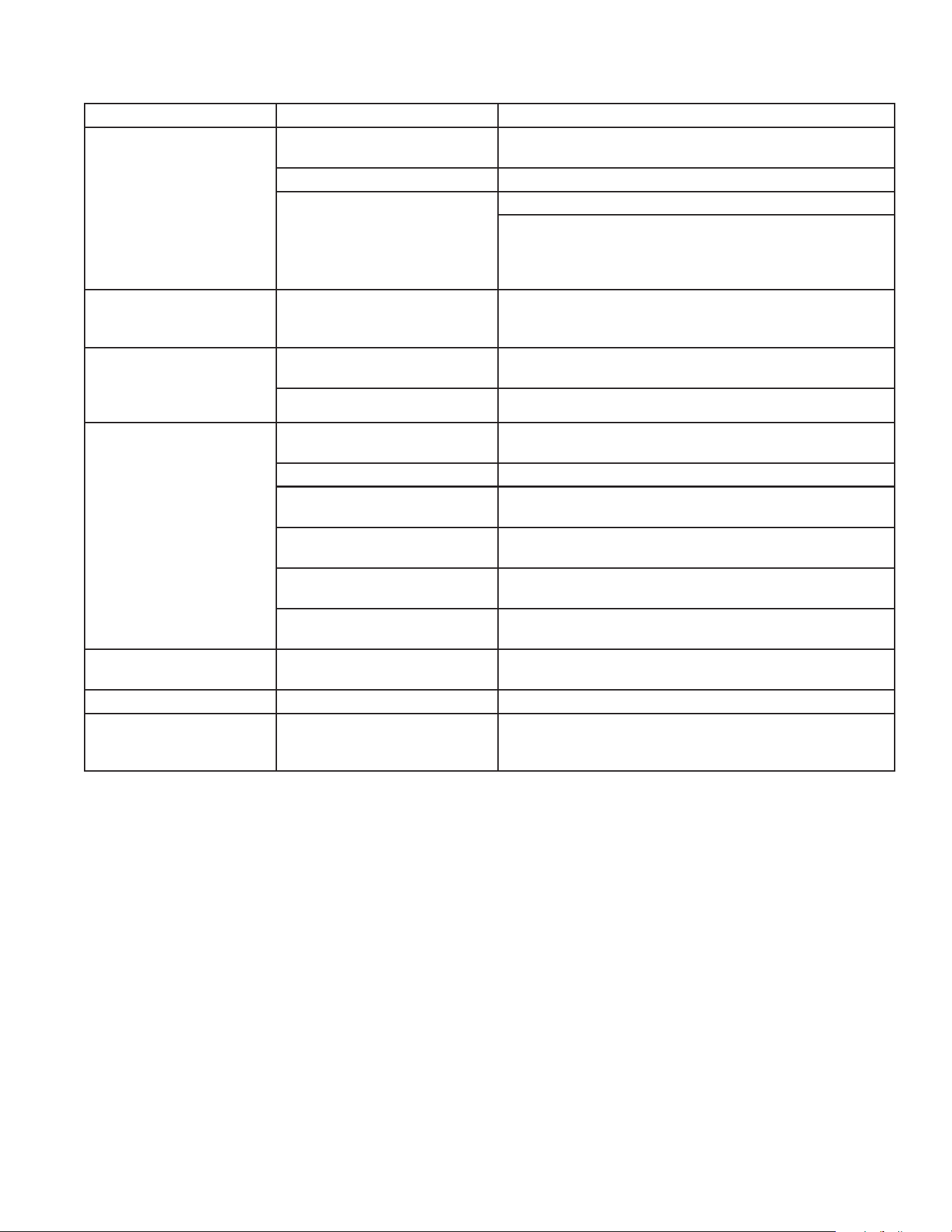
WARNING RISK OF UNIT BURSTING! DO NOT STORE OR
OPERATE UNIT IN A FREEZING ENVIRONMENT!
If you must store your unit in an area where the temperature may fall below
32°F, you can protect your unit by following the procedure outlined below.
1. Gather the following items:
a. Two 5 gallon containers.
b. One gallon of antifreeze. (The manufacturer recommends an
environmentally safe antifreeze.)
c. Water supply.
d. Three foot suction hose with a 1 1/2 inch cam and groove adapter
(#15-0212).
2. Procedure:
a. Shut off the unit and water supply.
b. In a 5 gallon container, mix the antifreeze and water according to
manufacturer's recommendations for the temperature to which you
are winterizing.
NOTE: Proper winterizing is based on the recommended manufacture's
instructions listed on the "Protection Chart" shown on the back label
of most antifreeze containers.
c. Remove the water supply hose from the unit and attach the 3 foot hose
securely to the inlet connection. Submerge the opposite end into the
antifreeze solution.
d. Point the wand into the empty container in cone mist mode.
e. Trigger the gun and start the unit. Continue until all the antifreeze mixture
is siphoned from the container.
f. Detach the 3 foot hose from the unit and drain any excess antifreeze
back into the 5 gallon container.
g. Disconnect the hose/gun/wand assembly from the unit and drain any
excess antifreeze back into the 5 gallon container.
h. Store the hose, gun and wand with the unit in a safe area.
i. Store antifreeze solution for next use or dispose of according to state
EPA laws.
3. Optional Procedure:
a. Shut off the unit and disconnect the pump inlet water supply hose.
b. Point the trigger gun in a safe direction and squeeze the trigger until
water ow ceases to exit the nozzle.
c. Disconnect and drain the hose, gun and wand.
d. Start the unit and allow it to run until all the water exits the unit. Once
the water has stopped owing from the unit, turn the unit off.
NOTE: When using this procedure, caution should be used as ice chips
can form from drops of water which could cause the unit to burst if
starting before completely thawed.
32˚F 0˚C
Operator's Manual 17
TROUBLESHOOTING
SYMPTOM PROBABLE CAUSE REMEDY
Pump motor will not start,
or stops
Tripped circuit breaker or fuse
blown in circuit fuse box
Disconnect all other plugs on the circuit being used
and reset circuit breaker OR check and replace fuse.
Loose or disconnected plug. Reconnect plug.
Unit components are frozen Allow to cool and restart unit.
Allow to thaw. If any part of the unit becomes frozen;
excessive pressure may build up in the unit which
could cause the unit to burst resulting in possible seri-
ous injury to the operator or bystanders.
Circuit breaker trips or
fuse blows the fuse box.
Circuit overload. Check that the circuit is rated in correctly. Disconnect
all plugs on the circuit. When connecting to a circuit
protected by fuses, use time delay fuses only.
Motor runs but there is
no discharge at nozzle
when trigger mechanism
is squeezed
Inadequate water supply. Ensure hose is 3/4" diameter and incoming water sup-
ply is turned on.
Kink in water inlet hose. Remove kink.
Low or uctuating pres-
sure.
Kink in high pressure dis-
charge hose.
Replace kinked pressure hose.
Water inlet screen obstructed. Remove screen, clean or replace.
Pump sucking air. (Prime
lost)
Tighten all water intake connections. Eliminate leaks in
intake line.
Obstructed or worn spray
nozzle.
Rmove and clean, or replace.
Damaged or obstructed valve
assy.
Remove, inspect, clean or replace.
Bypass valve not operating
correctly.
Repair or replace.
Oil appears milky or
foamy.
One or more diaphragms
have ruptured.
Replace diaphragms
Oil leaking from unit. DO NOT USE!!!!! Contact Customer Service.
Water ows from the noz-
zle when the trigger gun
is turned off.
Gun is malfunctioning. Repair or replace.

18 Operator's Manual
STATEMENT OF WARRANTY
The manufacturer warrants all parts, (except those referred to below), of your new belt
driven pressure washer to be free from defects in materials and workmanship during the
following periods:
For One (1) Years from the date of original purchase:
High Pressure Pump
For Two (2) Years from the date of original purchase:
Pulleys Plumbing
For One (1) Year from the date of original purchase:
Selector Switch Starter Contactor Overload
For Ninety (90) Days from the date of original purchase:
Trigger Gun/Wand High Pressure Hose Unloader Valve
Defective parts not subject to normal wear and tear will be repaired or replaced at our
option during the warranty period. In any event, reimbursement is limited to the pur-
chase price paid.
EXCLUSIONS
1. The motor is covered under separate warranty by its respective manufacturer and is
subject to the terms set forth therein.
2. Normal wear parts:
Pump Diaphrams Quick Couplings/Screw Connects Spray Nozzles
Detergent Valves Pump Valves O-rings
Belts
3. This warranty does not cover parts damaged due to normal wear, misapplication,
misuse, operation at other than recommended speeds, pressures or temperature. Parts
damaged or worn because of the use of caustic liquids or by operation in abrasive or
corrosive environments or under conditions of "starved suction" are not warranted.
Failure to follow recommended operating and maintenance procedures also voids
warranty.
4. The use of other than genuine repair parts will void warranty. Parts returned, prepaid
to our factory or to an Authorized Service Center will be inspected and replaced free of
charge if found to be defective and subject to warranty. There are no warranties which
extend beyond the description of the face hereof. Under no circumstances shall the
manufacturer bear any responsibility for loss of use of the unit, loss of time or rental,
inconvenience, commercial loss or consequential damages.
For Service or Warranty Consideration, contact:
563-556-7484 / 800-553-9053 / Fax 563-556-1235
Monday - Friday / 8:00 a.m. - 5:00 p.m. CST

Manual del Operador 19
NOTES

20 Manual del Operador
ADVERTENCIA: Este producto puede
exponerlo a productos químicos, incluido el
plomo, que el Estado de California conoce a
causar cáncer y defectos congénitos u otros
daños reproductivos. Para obtener más
información, visite www.P65Warnings.ca.gov
ADVERTENCIA
TABLA DE MATERIAS
NOTES ..........................................................................................................................................19
INTRODUCCION .........................................................................................................................21
ADVERTENCIAS IMPORTANTES DE SEGURIDAD .............................................................. 22
ELEMENTOS Y COMPONENTES .............................................................................................25
LISTA DE LOS ELEMENTOS Y COMPONENTES .................................................................. 25
ELEMENTOS Y COMPONENTES .............................................................................................26
LISTA DE LOS ELEMENTOS Y COMPONENTES .................................................................. 26
CALCOMANIAS DE SEGURIDAD Y UBICACION .................................................................. 27
INSTALACION Y PREPARACION ............................................................................................. 28
INSTRUCCIONES DE OPERACION ......................................................................................... 33
ALMACENAMIENTO Y MANTENIMIENTO .............................................................................. 35
LOCALIZACION DE FALLAS .................................................................................................... 38
DECLARACIÓN DE GARANTÍA ............................................................................................... 39
Manual del Operador 21
INTRODUCCION
¡Felicitaciones por la compra de su nueva lavadora a presión! Puede estar seguro que su lavadora a presión fue con-
struida con el nivel más alto de precisión y exactitud. Cada componente ha sido probado rigurosamente por técnic-
os para asegurar la calidad, la resistencia y el rendimiento de esta unidad.
Este manual del operador fue compilado para su benecio. Leyendo y siguiendo los pasos simples de seguridad,
instalación, operación, mantenimiento y localización de fallas descritos en este manual ayudará a prolongar aun más
la operación libre de fallas que usted puede esperar de su nueva lavadora a presión. El contenido de este manual
está basado en la información actualizada disponible al momento de la publicación. El fabricante se reserva el dere-
cho de efectuar cambios en precio, color, materiales, equipo, especicaciones o modelos en cualquier momento sin
previo aviso.
¡IMPORTANTE!
Estos párrafos están rodeados por una “CASILLA DE ALERTA DE SEGURIDAD”. Esta casilla se usa par designar
y enfatizar las Advertencias de Seguridad que deben seguirse al operar esta lavadora a presión. Acompañando
a las Advertencias de Seguridad están las “palabras de alerta” que designan el grado o nivel de seriedad de
riesgo. Las “palabras de alerta” usadas en este manual son las siguientes:
PELIGRO: INDICA UNA SITUACIÓN INMINENTE RIESGOSA LA CUAL, SI NO SE EVITA, RESULTARA EN LA
MUERTE O EN LESIONES GRAVES.
ADVERTENCIA: INDICA UNA SITUACIÓN POTENCIALMENTE RIESGOSA LA CUAL, SI NO SE EVITA,
PODRIA RESULTAR EN LA MUERTE O EN LESIONES GRAVES.
PRECAUCION: INDICA UNA SITUACIÓN POTENCIALMENTE RIESGOSA LA CUAL, SI NO SE EVITA PUEDE
RESULTAR ENLESIONES MENORES O MODERADAS.
El símbolo indicado a la izquierda de este párrafo es el “Símbolo de Alerta de Seguridad”. Este símbolo se usa
para alertarlo acerca de artículos o procedimientos que podrían ser peligrosos para usted u otras personas
usando este equipo.
PROVEA SIEMPRE UNA COPIA DE ESTE MANUAL A CUALQUIER PERSONA QUE USE ESTE EQUIPO. LEA
TODAS LAS INSTRUCCIONES ANTES DE OPERAR ESTA LAVADORA A PRESION, OBSERVANDO EN PARTIC-
ULAR LAS “ADVERTENCIAS DE SEGURIDAD” PARA EVITAR LA POSIBILIDAD DE LESIONES PERSONALES AL
OPERADOR.
Escriba el número de serie de su unidad en el espacio provisto abajo, una vez que la unidad haya sido desempaca-
da.
NUMERO DE SERIE___________________________
Inspeccione por daño el contenido de la caja. Si algo parece dañado, NO LA DEVUELVA AL LUGAR DE COMPRA.
Llame a su representante de servicio al cliente de al
800-553-9053
Monday - Friday
8:00 a.m. - 5:00 p.m. Central Standard Time
Por favor tenga disponible la información siguiente para todas las llamadas de servicio:
1. Número de modelo
2. Número de serie
3. Fecha y lugar de compra
22 Manual del Operador
ADVERTENCIAS IMPORTANTES DE SEGURIDAD
PRECAUCIONES ELECTRICAS:
1. INSTRUCCIONES DE CONEXION A TIERRA: Este equipo debe conectarse
a tierra. La conexión a tierra provee un camino de resistencia reducida a
la corriente eléctrica para reducir el riesgo de choque eléctrico, en caso
de malfuncionamiento o falla. Este producto está equipado con un cordón
que tiene un conductor de conexión a tierra del equipo y un enchufe de
conexión a tierra. El enchufe debe enchufarse a un tomacorriente apropiado
que esté correctamente instalado y conectado a tierra de acuerdo con
todos los códigos y ordenanzas locales.
2. PELIGRO: La conexión incorrecta del conductor de conexión a tierra del
equipo puede resultar en un riesgo de electrocución. Si usted tiene dudas
acerca de si el tomacorriente está correctamente conectado a tierra, consulte
con un electricista calicado o personal de servicio. No modique el enchufe
provisto con el producto. Haga instalar un tomacorriente apropiado por
un electricista calicado, si el enchufe no entra. No use ningún tipo de
adaptador con este equipo.
ADVERTENCIA MANTENGA TODAS LAS CONEXIONES SECAS
Y ALEJADAS DE TIERRA, PARA REDUCIR EL RIESGO DE
ELECTROCUCIÓN. NO PERMITA QUE LOS CORDONES
ELÉCTRICOS Y LAS CONEXIONES PERMANEZCAN EN AGUA O
EN UNA POSICIÓN EN LA QUE EL AGUA PODRÍA ENTRAR EN
CONTACTO CON ELLOS. NO TOQUE EL ENCHUFE CON LAS
MANOS MOJADAS.
3. Para desconectar del tomacorriente, NO tire del cordón eléctrico, NI
transporte la unidad por el cordón.
4. Antes de usar inspeccione por daños al cordón eléctrico. Existe un riesgo
de choque eléctrico resultante de daño por aplastamiento, corte o calor.
5. ASEGURESE siempre que la unidad está recibiendo el voltaje apropiado.
Asegúrese que el interruptor está en la posición “OFF”, antes de enchufar
la unidad a una fuente de potencia compatible. Desconecte cuando no se
usa.
6. NO use la unidad en un lugar donde puedan estar presentes vapores
inamables de gas. Una chispa eléctrica puede causar una explosión o
incendio.
7. NO dirija el rociado de agua a o dentro de instalaciones eléctricas de ningún
tipo. Esto incluye tomacorrientes eléctricos, lámparas eléctricas, cajas de
fusibles, transformadores, la unidad misma, etc. Puede ocurrir un choque
eléctrico grave.
8. El fabricante no recomienda que el usuario intente ninguna reparación
eléctrica a esta unidad.
PRECAUCIONES PARA ROCIADO:
¡PELIGRO! RIESGO DE INYECCION O DE LESIONES GRAVES DE
CORTE MANTENGASE ALEJADO DE LA BOQUILLA NO DIRIJA
LA CORRIENTE DE DESCARGA A LAS PERSONAS NI A LOS
ANIMALES DOMESTICOS DEBEN OBSERVARSE SIEMPRE
PRECAUCIONES BASICAS, INCLUYENDO LAS SIGUIENTES:
1. MANTENGASE ALEJADO DEL ROCIADO
a. Los uidos pueden penetrar la piel, causando lesiones graves, a causa
de la alta presión y velocidad del rociado.
b. Nunca apunte la pistola hacia usted ni hacia otra persona. Nunca
coloque su mano, dedos o cuerpo directamente sobre la boquilla de
rociado. Mantenga siempre el área de operación despejada de todas
las personas. Ejerza una precaución extrema al operar cerca de niños.
c. REQUIERA CUIDADO MEDICO DE EMERGENCIA si ocurriera un
accidente y el rocío parece haber penetrado la piel. NO LO TRATE
Manual del Operador 23
ADVERTENCIAS IMPORTANTES DE SEGURIDAD
COMO UN CORTE SIMPLE. Si usted está usando agentes limpiadores,
esté preparado a informar a su médico exactamente de qué clase.
2. SIEMPRE use antiparras protectoras al operar la unidad, para proteger los
ojos contra desechos despedidos y detergentes. Otros equipos protectores
tales como trajes de goma, guantes y respiradores son recomendables,
especialmente al usar detergentes de limpieza. Ejerza una precaución
extrema al operar cerca de niños.
3. Esté alerta - observe lo que hace. No opere la unidad cuando esté fatigado
o bajo la inuencia de alcohol o drogas.
4. NUNCA accione el gatillo a menos que la unidad esté rmemente sujeta.
El empuje del agua recorriendo la boquilla puede ser lo sucientemente
poderoso como para causar que el operador pierda el equilibrio si no
está preparado. NO SE INCLINE ni se pare sobre un apoyo inestable.
Las supercies húmedas pueden ser resbalosas, use equipo protector
de calzado y manténgase bien parado y en equilibrio en todo momento.
NUNCA accione el gatillo de la pistola mientras esté en una escalera o en
el techo.
5. NO dirija el rociado hacia materiales frágiles tales como vidrio. El astillado
podría resultar en lesiones graves.
6. SIEMPRE sujete rmemente el conjunto de pistola/vara al arrancar y
operar la unidad. El no hacerlo puede causar que la vara caiga y azote
peligrosamente. NUNCA opere la pistola con el gatillo conectado en la
posición abierta. La pistola a gatillo debería estar bien asegurado cuando
no se usa, para evitar una descarga accidental.
PRECAUCIONES MISCELANEAS DE SEGURIDAD:
1. ¡NUNCA PERMITA QUE LOS NIÑOS O ADOLESCENTES OPEREN ESTA
UNIDAD!
2. Lea y observe todas las instrucciones de manejo, funcionamiento,
mantenimiento y seguridad incluidas en este manual y facilite esta
información a TODAS LAS PERSONAS que operarán esta unidad.
3. La unidad debe estar sucientemente caliente como para asegurar que no
haya formación de hielo en la bomba, a temperaturas de congelación. NO
arranque esta unidad si ha sido transportada en un vehículo abierto o sin
suciente calefacción, sin permitir primero que la bomba se descongele.
4. Las mangueras de alta presión deberían inspeccionarse diariamente por
señas de desgaste. Si existe evidencia de falla, reemplace rápidamente
todas las mangueras sospechosas para evitar la posibilidad de lesiones
ocasionadas por rociado a alta presión. Si una manguera o adaptador está
perdiendo, NUNCA coloque su mano directamente sobre la pérdida.
5. NO opere la unidad si ve pérdidas de aceite de la bombao agua de la máquina.
NO reanude la operación hasta que la unidad haya sido inspeccionada y
reparada por una persona calicada de servicio.
6. No opere la unidad sin todas las cubiertas protectoras en su sitio.
7. NO deje desatendida la unidad presurizada. Apague la unidad y descargue
la presión interna antes de alejarse.
8. Apague el interruptor de la unidad.
PRECAUCIONES DE AJUSTE:
1. NUNCA altere ni modique el equipo, asegúrese que todos los artículos
accesorios y los componentes del sistema que se usan resistirán la presión
desarrollada. Use SOLO piezas genuinas el fabricante para reparar su
lavadora a presión. El no hacerlo puede causar condiciones operativas
riesgosas y cancelará la garantía.
2. NUNCA efectúe ajustes a la máquina mientras esté conectada al motor,
sin sacar primero el cable de encendido de la bujía. El girar la máquina a
24 Manual del Operador
ADVERTENCIAS IMPORTANTES DE SEGURIDAD
mano durante el ajuste o la limpieza podría arrancar el motor y la máquina,
lo que causará lesiones graves al operador.
3. Sepa cómo detener la lavadora a presión y purgar las presiones rápidamente.
Esté completamente familiarizado con los controles.
4. Apague la unidad, desconéctela de la red eléctrica, elimine la presión de
agua, y permita que la unidad se enfríe, antes de repararla. Preste servicio
en un área limpia, seca y plana.
5. Observe las instrucciones de mantenimiento especicadas en este manual.
Manual del Operador 25
ELEMENTOS Y COMPONENTES
LISTA DE LOS ELEMENTOS Y COMPONENTES
CHV-EEATURES-091106-JJT
1. Motor
2. Enchufe Eléctrico
3. Cable eléctrico
4. Interruptor
5. Arrancador
6. Calcomanía- Declaraciones de
Advertencia/Precaución
7. Caja Eléctrica
8. Aislador De la Bóveda
9. Válvula De Solenoide
10. Conexión De la Manguera Del Jardín
11. Enchufe Del Agua Dulce - Al Tanque
12. Salida de alta presión
13. Manguera De alta presión
14. Conjunto del la pistola
15. Calcomanía- Advertencia Riesgo de
Inyeccion
16. Palanca ajustable del patrón de aerosol
17. Arma de la gama larga con el inyector
18. Interruptor De Flujo
19. Entrada De Bomba
20. Aberturas De la Ventilación
21. Enchufe de puente
22. Bomba De Diafragma
23. Calcomanía- Beltguard en lugar
24. Vidrio de nivel de aceite
25. Salida de presión
26. Correa Cubierta
27. Palanca De la Descarga
26 Manual del Operador
ELEMENTOS Y COMPONENTES
LISTA DE LOS ELEMENTOS Y COMPONENTES
CHV AR PUMP FEATURES 112420
3
2
1
4
5
6 7
9 10 11
12
14
15 16 17 18 19
20
21
8
22
2324
27 26
25
13
1. Motor
2. Enchufe Eléctrico
3. Cable eléctrico
4. Interruptor
5. Arrancador
6. Calcomanía- Declaraciones de
Advertencia/Precaución
7. Caja Eléctrica
8. Bomba De Diafragma
9. Aislador De la Bóveda
10. Válvula De Solenoide
11. Conexión De la Manguera Del Jardín
12. Enchufe Del Agua Dulce - Al Tanque
13. Interruptor De Flujo
14. Salida de alta presión
15. Manguera De alta presión
16. Conjunto del la pistola
17. Calcomanía- Advertencia Riesgo de
Inyeccion
18. Palanca ajustable del patrón de aerosol
19. Arma de la gama larga con el inyector
20. Entrada De Bomba
21. Enchufe de puente
22. Aberturas De la Ventilación
23. Calcomanía- Beltguard en lugar
24. Vidrio de nivel de aceite
25. Correa Cubierta
26. Palanca De la Descarga
27. Salida de presión
Manual del Operador 27
CALCOMANIAS DE SEGURIDAD Y UBICACION
(NOTA: LAS CALCOMANÍAS DE SEGURIDAD ESTÁN EN INGLÉS SOLAMENTE!)
Calcomanía: Advertencia- Correa Cubierta
(Pieza No. 34-0575) (English Solamente)
Calcomanía: Declaraciones de Advertencia/Precaución (Pieza No. 34-0925) (English Solamente)
•Risk of Injection or Severe Injury: Keep clear of nozzle.
Do not direct high pressure spray at any person or self.
This machine is to be used by qualified operators.
•Risk of Electrocution: Do not direct spray toward any
electrical connections or outlets. Use extreme caution
while operating near any electrical power lines. Use
extreme safety precautions due to high voltage
involved.
•Risk of Explosion: Do not spray flammable liquids or in
an area containing combustible dust, liquids, or vapors.
•Risk of Injury: Use only properly rated components with
this unit. Close supervision is necessary when this
product in near children.
•Risk of Chemical Exposure: Use only water and
recommended detergents with this unit.
•Read and understand all instructions and
operation manual before using. Check local
codes regarding cross connection to water
supply.
•Stay alert: Hold on to gun/wand firmly with both
hands to avoid dangerous kickbacks.
•Do not overreach or stand on unstable support.
Keep good footing and balance at all times.
•Inspect all hoses for kinking, cuts, and leaks.
•Eye goggles and appropriate protection is
recommended while operating this unit.
•Protect pump from freezing.
•Always turn on water supply to pump before
starting.
•Engage trigger safety lock-off when not in use.
•Be certain that the motor switch is in the "OFF"
position before inserting plug into electrical outlet.
Be sure that the correct electrical system (voltage,
amp, capacity, etc.) is supplied for this unit.
•Turn on adequate water supply and trigger gun to
prime pump and release air.
•After starting the unit: Point gun in a safe
direction, brace wand securely to avoid recoil and
hold trigger.
•After stopping the unit, always turn off water
supply and trigger spray gun to release pressure.
•Observe lubrication and maintenance
recommendations as listed in the operator's
manual.
WARNING
CAUTION
OPERATION
34-0925-031802-ENG.
Calcomanía: Advertencia: Riesgo de inyección (Pieza No. 34-1253)
RISK OF INJECTION OR SEVERE INJURY.
Never put your hand, fingers or body directly
over the spray nozzle.
34-1253-030801-ENG.
WARNING
ADVERTENCIA
RIESGO DE INYECCION O LISION SEVERA
Nunca coloque la mano, los dedos o el cuerpo
directamente sobre la boquilla de rocío.
28 Manual del Operador
INSTALACION Y PREPARACION
PROTECCIÓN PERSONAL:
Ponerse la protección personal adecuada es vital para la propia seguridad. Se
recomienda utilizar lo que sea necesario para protegerse los ojos, oídos y piel.
PREPARACIÓN:
PELIGRO RIESGO DE EXPLOSION! NO COLOQUE LA UNIDAD EN
UN AREA DONDE PUEDAN ESTAR PRESENTESE VAPORES
INFLAMMABLES. UNIA CHISPA PODRIA CAUSAR UNA
EXPLOSION.
RIESGO QUE LA UNIDAD REVIENTE! NO ALMACENE/OPERE LA
UNIDADA EN U ABIENTE HELADO.
1. Esta unidad sólo debe colocarse en una supercie a nivel para asegurar
una lubricación adecuada de la bomba de agua durante el funcionamiento.
NUNCA rocíe agua directamente en la unidad.
2. No use la unidad en áreas:
a. donde existan señales de fugas de aceite o combustible.
b. donde pueda haber presencia de vapores de gases inamables.
3. No exponga la unidad a la lluvia, nieve o temperaturas de congelación. Si
se congela alguna parte de la unidad, puede acumularse presión excesiva,
la cual puede causar que reviente la unidad y se produzcan lesiones graves
al operador y a los circunstantes.
4. Debe revisarse el nivel de aceite de la bomba. Asegúrese de que el aceite
llegue a la marca de "lleno" de la vara de nivel o del centro de la mirilla de
nivel del aceite. Si parece bajo el nivel, llene el tanque con aceite. Consulte
la placa de datos de la bomba para conocer el tipo de aceite.
LA CONEXIÓN TÍPICA DEL SUMINISTRO DE AGUA:
1. Escoja una manguera de jardín que mide por lo menos 3/4 ID y no más
largo que 50 pies. Conecte un n de la manguera de jardín del suministro
del agua de preparado a la cala del preparado de la unidad. Conecte el
otro n de la manga a su suministro de agua presurizado.
La nota: Al conectar el suministro de agua de trago de cala de prepara-
do las regulaciones principal y locales de su compañía de agua se
deben observar. En algunas áreas, la unidad no debe ser conectada
directamente al público que bebe suministro del agua. Esto deberá
asegurar que no hay reacción en el suministro de agua. (Dirija la
conexión se permite si un preventor del flujo de espalda se instala.)
2. Conecte la manga de preparado de agua de la unidad al tanque. (Opcionales
C-0072 Tanque). Veinte cinco pies de 3/4" manga #15-0033 baja de la
presión son suministrados con la unidad. El suministro de preparado de
agua sólo no suministrará los requisitos de agua de la unidad.
La nota: La bomba de diafragma no sufrirá si se agota debido a ningún
tanque vacío. Sin embargo una succión “privar de algo” debido a
un colador atascado o cerró válvula en la línea de cala de bomba
causará el fracaso prematuro del diaphrams de bomba.
3. Conecte una manga de cala que no es plegable de 1-1/2 pulgada
del tanque a la cala de la bomba. La manga y los conectores no son
suministrados con la unidad. 1-1/2” una manga que no es plegable #150212
y conector de la leva y acanala #55-0053 (dos son requeridos) puede ser
comprado separadamente. Veinte cinco pies de manga con conectores
son suministrados con CX-0072. La instalación típica incluye un cerrado
de válvula de pelota (válvula de succión) y un ltero de área grande 10-20
pantalla de malla (incluyó con CX-0072). Nunca utilice una pantalla na
del ltro con una bomba de diafragma.
4. Conecte evite manga de salida de la bomba al tanque. Veinte cinco pies de

Manual del Operador 29
INSTALACION Y PREPARACION
3/4" manga #15-0033 baja de la presión (50 pies totalizan) es suministrado
con la unidad.
5. Conecta-Rápido la manga alta de la descarga de la presión a la salida del
agua del teh de la unidad. Conecte el otro n de la manga de la descarga
al fusil.
6. Una bomba del sumidero de un sistema del hoyo o la recirculación es
dirigida típicamente al tanque para proporcionar suciente agua para
mantener el tanque de acabarse. (No Suministró).
7. Una manga de la capacidad excesiva de la cima del tanque es dirigida
típicamente atrás al hoyo.
UNIDAD DE CONTROL
La presion se ha jado en la fabrica y debe solo sea ajustado por un repre-
sentante entrenado de servicio de atencion al cliente el fabricante.
EL APAGADOR DE PULSACION:
Es la naturaleza de bombas de diafragma para tener alguna pulsación.
Esto es causado por cambios repentinos en la dirección de pitón. El apa-
gador de la pulsación tiene una función en el sistema del bombeo, reduce
la pulsación proporcionando un cojín de aire para golpear. El apagador de
la pulsación utiliza una vesícula de caucho al seperate el cojín aéreo de la
solución se bombeando. La regla básica deberá llenar el apagador de la
pulsación al veinte por ciento (20%) de sistema de que trabaja la presión.
Si usted tiene su conjunto de la presión que rocía en 100 psi, la colocación
para el apagador de la pulsación debe ser 20 psi. Siempre cierre la bomba
antes de agregar aire al apagador de la pulsación o vericar su presión. El
suministro aéreo puede ser de un compresor o una bomba manual del tipo.
La cúpula que contiene aire es pequeña. Tome el cuidado para aplicar el
guage de la presión uniformemente en el respiradero para prevenir aire de
salir fuera del apagador de pulsación. No es raro para perder 5-10 psi al ver-
icar la presión del apagador de la pulsación. La nota: 2 bombas de diaph-
ram de cilindro pueden requerir más aire que 20% de la presión operadora.
20 psi es la presión mínima de apagador de pulsación. NO CORRA BOMBA
CON MENOS DE 20 PSI EN EL APAGADOR DE LA PULSACIÓN.
CONEXIÓN DEL CABLE DE ALIMENTACIÓN ELÉCTRICA:
ADVERTENCIA ¡RIESGO DE ELECTROCUCIÓN! ESTA UNIDAD
DEBE CONECTARSE A UNA TOMA DE CORRIENTE CON LA
DEBIDA CONEXIÓN A TIERRA. NO USE NINGÚN ADAPTADOR
NI ELIMINE EL CONTACTO DE TIERRA.
1. El interruptor debe estar en la posición de apagado (OFF).
2. La fuente de voltaje debe ser idéntica a las especicaciones indicadas en
la placa de datos de la lavadora.
3. Debe manterse seca el área existente entre la lavadora de chorro a presión
y la toma de corriente.
4. Inserte la clavija en una toma de corriente alterna (CA). ¡¡NO use adaptadores
NI retire la clavija de conexión a tierra!!
PROCEDIMIENTOS DE INSPECCION DE PREARRANQUE:
Efectúe los procedimientos siguientes antes de arrancar la unidad:
1. Inspeccione el nivel de aceite en la bomba y en el motor.
2. Inspeccione el tamiz de entrada de agua. Limpie o reemplace si fuera
necesario.
3. Inspeccione todas las conexiones de las mangueras para asegurar que
estén bien ajustadas.
4. Abra Válvula de Succión y Revise líneas de succión, los accesorios y ltro.
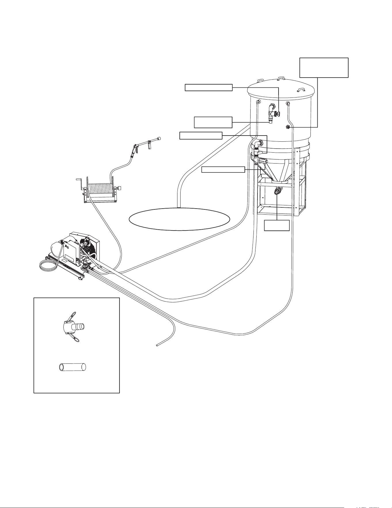
30 Manual del Operador
INSTALACION Y PREPARACION
VENDIDO SEPARADAMENTE
1 1/2' LEVA Y ACANALA EL ADAPTADOR -
DOS CON CX-0072
1 1/2” LA MANGA DE LA SUCCIÓN ORDENÓ
POR PIE 25' CON CX-0072 OPCIÓN
3/4" MANGUERA DE
JARDÍN PARA
PREPARAR AGUA CALA
UNIDAD DE CHV
LA PRESIÓN ALTA 50 PIES.
LA MANGA DE LA SALIDA
(CON LA UNIDAD)
CARRETE OPCIONAL
DE MANGA 50-0185
EL FUSIL A LARGO
PLAZO CON BOCA
(CON LA UNIDAD)
3/4" MANGA BAJA DE LA
PRESIÓN PARA PREPARAR
CISTERNA CALA 25'
CON LA UNIDAD (15-0033)
MANGA QUE NO ES
PLEGABLE DE CHV
25' CON CX-0072 (15-0212)
3/4" MANGA DE BYPASS Y
DE SALIDA CON PRESIÓN BAJA
25' CON LA UNIDAD (15-0033)
SISTEMA DE AGUA RECIRCULACIÓN/EL
HOYO/BOMBA DE SUMIDERO
MANGA DE CAPACIDAD
EXCESIVA Y INSTALA TÍPICA
FILTRO DE ENTRADA
VÁLVULA DE PELOTA
TIPICA DE BOMBA
DE SUMIDERO
VÁLVULA DE APAGADO
TANQUE OPCIONAL
DE DEMORA DE AGUA
CX-0072
FLOTE VÁLVULA EN EL
CAMPO DEL TANQUE
INSTALÓ ALAMBRADOT
DESCARGA
DE FANGO

Manual del Operador 31
INSTALACION Y PREPARACION
5. Inspeccione por pérdidas de combustible del sistema. Asegúrese que se
reemplacen todas las piezas dañadas y que se corrijan todos los problemas
mecánicos antes de operar la unidad. Consulte con el Servicio al Cliente
el fabricante, si usted requiere servicio.
6. La bomba de diafragma no sufrirá si se agota debido a un tanque vacío.
Sin embargo una succión "privar de algo" debido a un colador atascado
o cerró la succión válvula causará un fracaso prematuro de diafragma de
bomba.
7. Inspeccione las mangueras de alta presión por dobleces, cortes y pérdidas.
Asegúrese que se reemplacen todas las piezas dañadas y que se corrijan
los problemas mecánicos antes de operar la unidad. Consulte con el
Servicio al Cliente, si usted requiere servicio.
8. Inspeccione los cordones electricos para cortes. Si encuentre unos cortes,
NO TOQUÉ NI USE CORDÓN! Antes de arrancar reponza el cordon.
32 Manual del Operador
ADVERTENCIA
LAS PAGINAS SIGUIENTES CONTIENEN INSTRUCCIONES DE OPERACION Y
MANTENIMIENTO
NO TRATE DE OPERAR ESTA LAVADORA A PRESION HASTA QUE HAYA LEIDO Y
ENTENDIDO TODAS LAS PRECAUCIONES E INSTRUCCIONES DE SEGURIDAD LISTADAS
EN ESTE MANUAL.
¡¡LA OPERACION INCORRECTA DE ESTA UNIDAD PUEDE CAUSAR LESIONES GRAVES!!
¡¡DE NINGUNA MANERA ALTERE O MODIFIQUE ESTE EQUIPO!!
Manual del Operador 33
INSTRUCCIONES DE OPERACION
EMPIECE PARA ARRIBA:
1. Reérase a las "Precauciones de la Seguridad" antes de empezar la unidad.
2. Coloque la manga alta de la presión fuera quitar algunos aros. El ujo del
agua apretará la manga que crea los lazos apretados si la manga no es
recta.
3. Conecte seguramente la asamblea de fusil/varita a la manga alta de la
presión.
4. Empuje la palanca del manual descarga válvula hacia abajo tan la bomba
empezará en evita el modo. Prenda el suministro de agua completamente.
ADVERTENCIA ¡RIESGO DE INYECCION CAUSANTE DE LESIONES
GRAVES! ¡MANTENGASE ALEJADO DE LA BOQUILLA!
¡NUNCA COLOQUE LA MANO NI LOS DEDOS ENFRENTE DE
LA BOQUILLA! ¡NO DIRIJA LA CORRIENTE DE DESCARGA
HACIA LAS PERSONAS O LOS ANIMALES DOMESTICOS!
¡PARA PREVENIR UNA DESCARGA ACCIDENTAL ASEGURESE
QUE EL CONJUNTO DE LA BOQUILLA AJUSTABLE ESTE
SEGURAMENTE CONECTADO A LA VARA!
5. La bomba de diafragma no sufrirá si se agota debido a un tanque vacío.
Sin embargo una succión "privar de algo" debido a una pantalla atascada
del colador o un cerró la succión válvula causará el fracaso prematuro
de diafragma de bomba. Importante: Mantenga válvula de succión abre
siempre que sistema es operado.
6. Mueva el interruptor de basculador al posición de ON y empuje el botón
verde del comienzo para prender la unidad.
7. El agua empezará uir por el evita espalda de manga al tanque del suministro
de agua. Esto permite la unidad para preparar y purga cualquier aire del
sistema. La unidad es preparado cuándo ujo de agua no es interrumpido
por avión.
8. Vuelva la palanca del descarga válvula a posición de "ARRIBA".
9. Señale el fusil en una dirección segura y apriete el disparador. Refuércelo,
como el fusil hace comisión condencial de la fuerza del agua que sale la
boca.
10. Una vez que la unidad es prendida, realice los procedimientos siguientes
con el fusil abren:
a. Inspeccione para escapes de agua o petróleo en el sistema. ¡Si un
escape es encontrado, APAGUE LA UNIDAD! Esté seguro que todas
partes dañadas son reemplazadas y que los problemas mecánicos
son corregidos antes de la operación de la unidad. Si usted requiere
el servicio, contacte el servicio de atención al cliente.
b. Inspeccione manga alta de presión para enroscar, los cortes o los
escapes. ¡Si un corte o el escape son encontrados, NO TOCA MANGA
EN EL CORTE O ESCAPE! ¡APAGUE LA UNIDAD! Reemplace manga
antes de volver a encender la unidad. Esté seguro que todas partes
dañadas son reemplazadas adn que los problemas mecánicos son
corregidos antes de la operación de la unidad. Si usted requiere el
servicio, servicio de atención al cliente de contacto.
c. Inspeccione cuerda eléctrica para cortes. ¡Si un corte si encontró, NO
TOCA CUERDA ELECTRICA EN EL CORTE!! ¡APAGUE LA UNIDAD
INMEDIATAMENTE!
11. Provoque el fusil varias veces. ¡Nunca mire directamente en la boca! ¡El
agua alta de la presión crea un riesgo de la herida severa!
PRECAUCION RIESGO DE DAÑO NO DIRIJA CONTINUAMENTE EL
PATRON DE ROCIADO EN UNA SECCION DE LA SUPERFICIE
DURANTE UN PERIODO PROLONGADO DE TIEMPO. PUEDEN
OCURRIR POSIBLES DAÑOS.

34 Manual del Operador
INSTRUCCIONES DE OPERACION
APAGADO:
1. La unidad es equipada con apagado de demora del tiempo. Apague
automaticamente cuando el fusil no ha sido provocado durante la colocacion
del reloj.
2. Mueva el interruptor de basculador a la posicion de "OFF" antes de salir
la unidad. No salga la unidad desatendida sin la vuelta de el interruptor de
basculador a la posicion de "off". La unidad puede volver a encender por
un espacio de tiempo corto despues de agagar de la demora del tiempo
sea activiado si el fusil es apretado durante ese tiempo.
3. Desconecte la unidad de la fuente del poder.
4. Gire "make-up" de la manguera de jardin de agua "OFF".
5. Señalar el fusil en una direccion segura, provoca el fusil para asegurar que
no hay presion que es atrapada.
6. Desconecte y desague el fusil, la varita, y las mangas.
7. Limpie la unidad. Almacene el fusil, la varita y las mangas en un area segura.
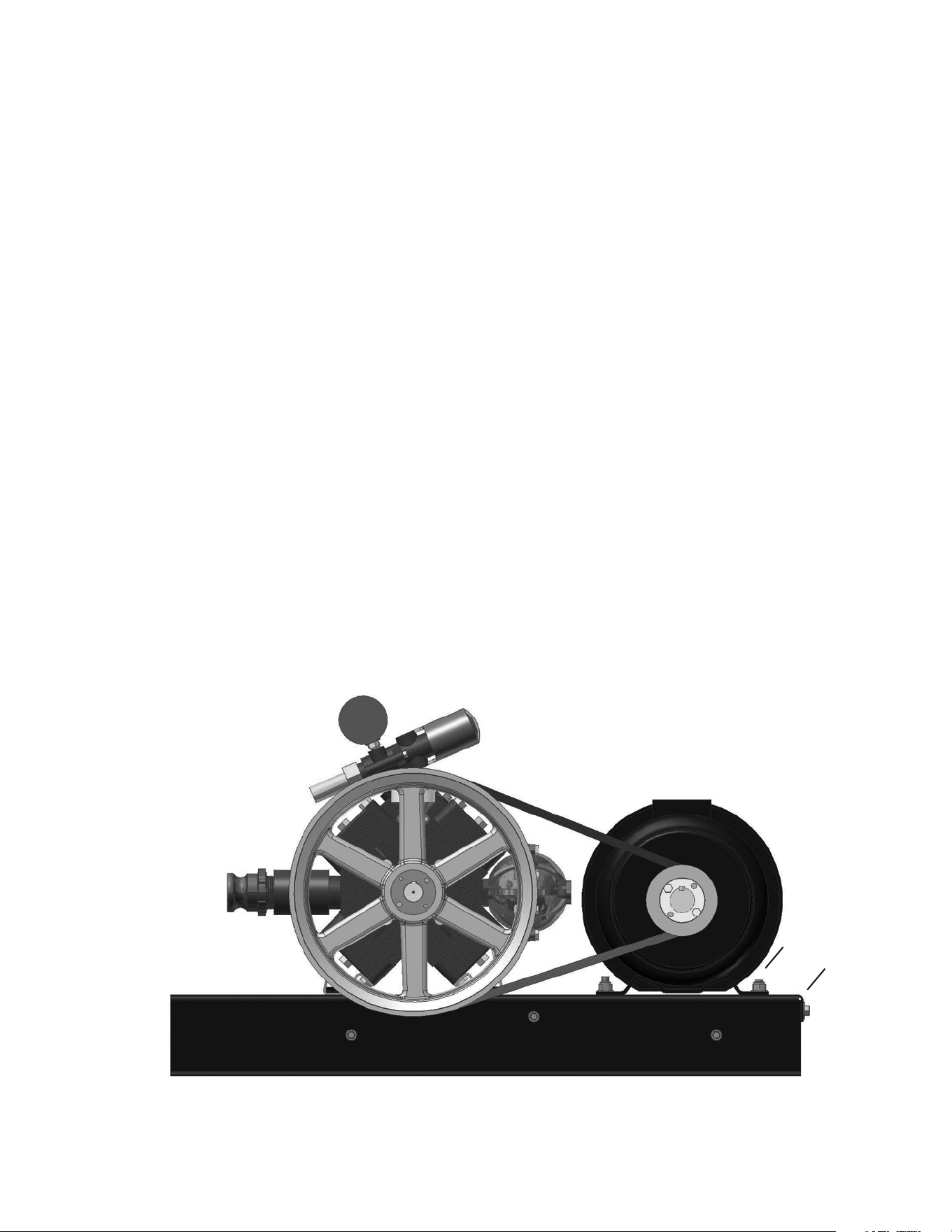
Manual del Operador 35
ALMACENAMIENTO Y MANTENIMIENTO
MANTENIMIENTO ESPECIFICO:
BOMBA: Cambio si el aceite parece sucio o lechoso. Consulte la placa de
datos para conocer el tipo de aceite. Llene solo hasta la marca en el vaso.
NO llene en exceso. Cambie Diafragmas de la Bomba cada 500 horas.
Inspeccione válvulas de cheque para la fatiga de la primavera y el uso del
asiento.
BOQUILLAS: El agua que uye a través de la boquilla de rociado de con-
exión rápida desgastará y agrandará el oricio, resultando en una pérdida
de presión. Deberían reemplazarse las boquillas siempre que la presión sea
menor que el 85% del máximo. La frecuencia de reemplazo dependerá de
tales variables tales como el contenido mineral en el agua y el número de
horas que se usa la boquilla.
AJUSTE DE TENSIÓN DE CORREAS: Para mantener la máxima eciencia
de su lavadora de alta presión, puede ser necesario ajustar la tensión de las
correas ocasionaimente. Siga el procedimiento que se describe a continu-
ación.
1. Quite el protector de correas y aoje las tuercas que están a los lados de
la motor (Referencia A). Hay un total de 4 tuercas.
2. Gire el tornillo (Referencia B) en el sentido de las manecillas del reloj hasta
observar que la correa se exiona una 1/2 pulgada (1,3 cm) entre las poleas.
3. Apriete las motor laterales (Referencia A).
4. Ponga una regla tocando el costado de ambasoleas. para comprobar la
alineación de la correa
5. Vuelva a poner la protección y apriete los sujetadores rmemente.
A
B
AJUSTE DE LA TENSIÓN DE LA CORREA
36 Manual del Operador
ALMACENAMIENTO Y MANTENIMIENTO
PREPARACION PARA EL INVIERNO:
Será necesario preparar esta unidad para el invierno, para nes de Alma-
cenamiento y transporte en temperaturas ambiente inferiores al punto de
congelación. Esta unidad debe protegerse contra la temperatura más baja
incurrida por las siguientes razones:
1. Si se congela cualquier parte del sistema de bombeo puede acumularse
una presión excesiva en la unidad, lo que podría causar que la misma
reviente resultando en lesiones posibles graves al operador o a los
observadores.
2. El sistema de bombeo de esta unidad puede resultar dañado
permanentemente si se congela. LOS DAÑOS POR CONGELACION NO
ESTAN CUBIERTOS POR LA GARANTIA.
ADVERTENCIA ¡RIESGO QUE LA UNIDAD REVIENTE! ¡NO
ALMACENE/OPERE LA UNIDAD EN UN AMBIENTE HELADO!
Usted puede proteger su unidad siguiendo el procedimiento indicado abajo,
si debe almacenarla en un lugar donde la temperatura puede descender por
debajo de los 32°F.
1. Reúne los artículos siguientes:
a. Dos recipientes de 5 galones.
b. Un galón de anticongelante. (el fabricante recomienda un anticongelante
seguro para el medio ambiente.)
c. Suministro de agua.
d. Manguera de la succión de tres pies, con 1 1/2"levas y adaptadores
del surco (#15-0212).
2. Procedimiento:
a. Después de hacerla funcionar y cebarla.
b. En un recipiente de cinco galones, mezcla el anticon-gelante y água
según las recomendaciones del fabricante para la temperatura loque
esta preparando para el invierno.
NOTA: La preparación apropiada para el invierno está basada en las
instrucciones recomendadas del fabricante incluidas en la “Tabla
de Protección” mostrada en el rótulo posterior de la mayoría de los
recipientes de anticongelantes.
c. Retire la manguera de suministro de agua de la unidad y fije
seguramente la manguera de 3 pies a la conexión de entrada. Sumerja
el otro extremo de la manguera del anticongelantes.
d. Apunte la vara hacia el recipiente vacío en modo de la niebla del cono.
e. Accione el arma y comience la unidad. Continúe ciclando la pistola
varias veces hasta que toda la mezcla anticongelante es extraída del
recipiente por la acción de sifón.
f. Separe la manguera de 3 pies de la unidad y drene todo el exceso
restante de anticongelante dentro del reciente de 5 galones.
g. Desconecte el conjunto de manguera/pistola/vara de la unidad y drene
todo el exceso restante de anticongelante dentro del recipiente de 5
galones.
h. Almacene la manguera, la pistola y vara junto con la unidad, en un
lugar seguro.
i. Almecene la solución anticongelante para un uso ulterior o descártela
de acuerdo con las leyes de protección del medio ambiente
correspondientes.
3. Procedimiento opcional:
a. Apague la unidad y desconecte la manguera del abastecimiento de
agua de la entrada de bomba.
32˚F 0˚C

Manual del Operador 37
ALMACENAMIENTO Y MANTENIMIENTO
b. Elimine la presión del sistema apuntando la pistola a gatillo hacia una
dirección segura y accionando el gatillo hasta que el ujo de agua cese
de salir por la boquilla.
c. Desconecte y drene la manguera, la pistola y la vara.
d. Arranque la unidad y permita que funcione hasta que toda el agua
salga de la misma. Apague una vez que el agua ha cesado de uir de
la unidad.
NOTA: Debe ejercerse precaución al usar este procedimiento, ya que
pueden formarse plaquitas de hielo de las gotas de agua, lo que
podría causar que la unidad reviente si se arranca antes de estar
completamente descongelada.
38 Manual del Operador
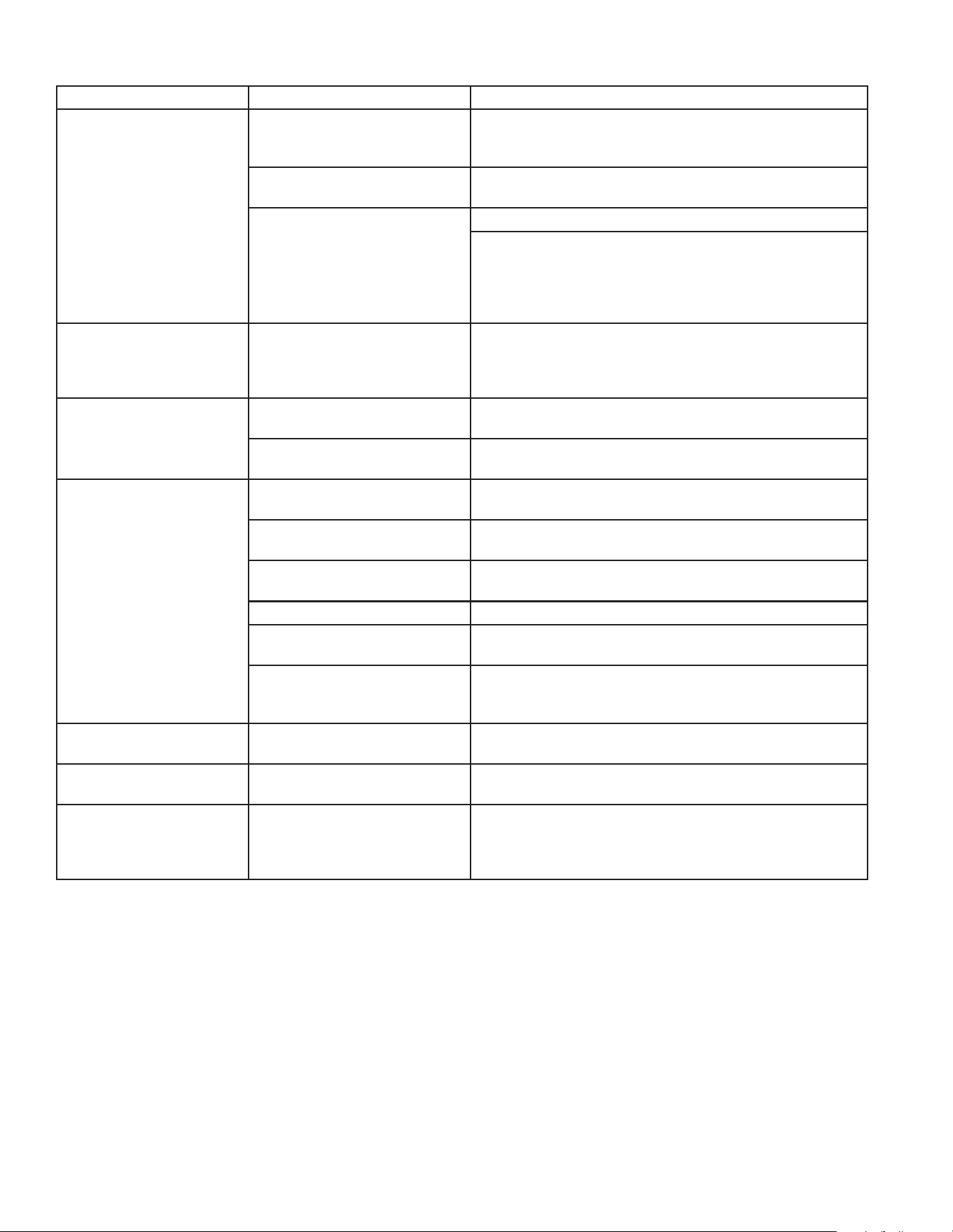
LOCALIZACION DE FALLAS
SINTOMA CAUSA PROBABLE SOLUCION
El motor de la bomba no
arranca o se apaga du-
rante el funcionamiento.
Interruptor de circuito activa-
do o circuito quemado en la
caja de fusibles.
Desconecte todos los otros enchufes del circuito que
está siendo usado y repongael interruptor de circuito o
inspeccione y reemplace elfusible.
Enchufe ojo o desconecta-
do.
Vuelva a conectar el enchufe.
Los componentes de la uni-
dad están congelados.
Deje que se enfríe y reinicie la unidad.
Permita que se descongele Si alguna parte de la uni-
dad se congela, es posible que se acumule la presión,
lo cual podría ocasionar que la unidad reviente y con-
secuentemente provoque lesiones graves al operador
o las personas que se encuentren alrededor.
Se activa el interruptor
de circuito o se quema
el fusible en la caja de
fusibles.
Sobrecarga del circuito. Verique que el circuito esté clasicado a 15 amperios
o más. Desconecte todos los enchufes en el circuito.
El motor funciona pero
no hay quema el fusible
en la caja de acciona el
mecanismo del gatillo.
Suministro inadecuado de
agua.
Asegure que la manguera tenga ¾” de diámetro y que
esté abiertoel suministro de agua entrante.
Doblez en la manguera de
entrada de agua.
Elimine el doblez.
Presión baja o uctuante. Doblez en la manguera de
discarga de alta presión.
Reemplace la manguera.
Está obstruido el tamiz de la
entrada de agua.
Retire el ltro, limpie o reemplace.
La bomba absorbe aire (elimi-
nado el cebado).
Ajuste todas las conexiones de toma de agua. Elimine
pérdidas en la línea de toma.
Oricio obstruido o gastado. Retire y limpie, o reemplace.
Conjunto de válvula dañado u
obstruido.
Retire y limpie, o reemplace.
La válvula de derivación no
está funcionando correcta-
mente.
Repárelos o cámbielos.
Aceite lechoso o espu-
moso.
Unos o más diafragmas han
roto.
Substituya los diafragmas.
Fuga de aceite en la
unidad.
¡¡¡¡¡NO UTILICE!!!!! Hable al dep de servicio alcliente.
Cuando la pistola de ga-
tillo está asegurado en la
posición "OFF", el agua
uye desde la boquilla.
La pistola funciona mal. Repárelos o cámbielos.

DECLARACIÓN DE GARANTÍA
El fabricante garantiza que todas las piezas (excepto aquellas a las que se hace refer-
encia abajo), de su nueva lavadora a presión libres de defectos en materiales y mano de
obra durante los periodos siguientes:
De la fecha original de compra
Bomba de Alta Presión
Por dos (2) años a partir de la fecha original de compra:
Cañerías Polea
Por una (1) años a partir de la fecha original de compra:
Encender de selector Contacto de entrada Sobrecarga
Por noventa (90) días a partir de la fecha original de compra:
Manguera de alta Presión Pistola de Gatillo
Descargador
Las piezas defectuosas que no están sujetas a deterioro causado por el uso serán repa-
radas o reemplazadas a nuestra opción durante el periodo de garantía. En todo caso, el
reembolso está limitado al precio de compra pagado.
EXCLUSIONES
1. El motor está cubierto bajo una garantía separada proporcionada por el fabricante
respectivo y está sujeta a los términos en ella establecidos.
2. Partes de desgaste normal:
Empaques de las Bombas Válvulas de la Bomba
Inyector de aerosol Boquillas Círculo
Correa Connexión Rapida/Conectar un tornillo
3. Esta garantía no cubre las piezas dañadas debido al deterioro normal causado por
el uso, mala aplicación, mal uso, operación a velocidades, presiones o temperaturas
diferentes a las recomendadas. Las piezas dañadas o gastadas a causa del uso de
líquidos cáusticos o por la operación en medios ambientes abrasivos o corrosivos o
bajo condiciones que causan cavitación de la bomba no están garantizadas. La falla
en seguir los procedimientos recomendados de operación y mantenimiento también
cancela la garantía.
4. El uso de piezas de repuesto diferentes a las genuinas el fabricante cancelará la garantía.
Las piezas devueltas, con franqueo pagado a un Centro de Servicio Autorizado serán
inspeccionadas y reemplazadas, libre de cargos, si se determina que están defectuosas
y sujetas a la garantía. No existen garantías que se extiendan más allá de la descripción
contenida aquí. Bajo ninguna circunstancia Corporation será responsable por la pérdida
de uso de la unidad, pérdida de tiempo, inconvenientes, pérdida comercial o daños
consecuentes.
PARA SERVICIO O CONSIDERACION DE LA GARANTIA CONSULTE CON:
TELEFONO: 563-556-7484/TELEFONE GRATIS EN LOS EE. UU.: 800-553-9053
FAX 563-556-1235 LUNES - VIERNES 8:00 A.M. - 5:00 P.M. CST

40 Manual del Operador